Effect of Friction Stir Welding on Microstructural and ... · engineering components in this study,...
10
ADVANCES in NATURAL and APPLIED SCIENCES ISSN: 1995-0772 Published BYAENSI Publication EISSN: 1998-1090 http://www.aensiweb.com/ANAS 2017 April 11(4): pages 484-493 Open Access Journal ToCite ThisArticle: Dr. K. Lenin and S. Dharmalingam. M.E.,(Ph.D)., Effect of Friction Stir Welding on Microstructural and Mechanical Properties of Copper Alloy. Advances in Natural and Applied Sciences. 11(4); Pages: 484-493 Effect of Friction Stir Welding on Microstructural and Mechanical Properties of Copper Alloy 1 Dr. K. Lenin and 2 S. Dharmalingam. M.E.,(Ph.D) 1 Associate Professor, Mechanical Engg. Department, Jayaram College of engg & tech, Tamilnadu. 2 Assistant Professor, Mechanical Engg. Department, OAS institute of tech & management, Tamilnadu. Received 28 January 2017; Accepted 22 April 2017; Available online 1 May 2017 Address For Correspondence: Dr. K. Lenin, Associate Professor, Mechanical Engg. Department, Jayaram College of engg & tech, Tamilnadu. Copyright © 2017 by authors and American-Eurasian Network for ScientificInformation (AENSI Publication). This work is licensed under the Creative Commons Attribution International License (CC BY). http://creativecommons.org/licenses/by/4.0/ ABSTRACT This study demonstrates the feasibility of joining the commercial pure copper plates by friction stir welding (FSW). Microstructure, micro hardness and tensile properties in terms of the joint efficiency were found 94.03 % compare to as receive base material (BM). The average hardness at the top was higher than bottom. Hardness of weld zone was higher than the base material. Different microstructure zones were revealed by optical microscopy and scanning electron microscopy. The stirred zone (SZ) exhibited primary two phases namely, recrystallized grains and fine precipitates in matrix of copper. KEYWORDS: INTRODUCTION Nowadays, researchers have been focusing on developing fast and eco-friendly processes in Manufacturing and this include Friction Stir Welding (FSW) and Processing (FSP). Friction Stir Welding (FSW) is a solid – state joining technique invented and patented by The Welding Institute (TWI) in 1991 for butt and lap welding of ferrous and non–ferrous metals and plastics. FSW is a continuous process that involves plunging a portion of a specially shaped rotating tool between the butting faces of the joint. The relative motion between the tool and the substrate generates frictional heat that creates a plasticized region around the immersed portion of the tool Friction stir welding (FSW) is a new solid state welding process, where the weld is produced by softening, plastic deformation combined with forging action caused by tool rotation of base metal (Fig. 1). Absence of melting of base metal in FSW reduces oxidation, residual stress, solidification related defects. The microstructure of the weld generally shows a central weld nugget with onion ring structure, a thermo- mechanically affected zone (TMAZ) close to the nugget, and a very small heat affected zone (HAZ). Recently many reports on friction stir welding of various metal system such as aluminium], magnesium, mild steel, stainless steel, and dissimilar systems such as aluminium to stainless steel, aluminium to steel, aluminium to copper, aluminium to magnesium, have been published. Preliminary studies on the FSW for copper to copper and brass have also been reported. Copper and its alloys are widely used in industrial applications due to their excellent electrical and thermal conductivities, good strength, and corrosion and fatigue resistances. However, welding of copper is usually difficult by conventional fusion welding techniques because of its high thermal diffusivity, which is 10–100 times higher than that of
Transcript of Effect of Friction Stir Welding on Microstructural and ... · engineering components in this study,...
ADVANCES in NATURAL and APPLIED SCIENCES
ISSN: 1995-0772 Published BYAENSI Publication EISSN: 1998-1090 http://www.aensiweb.com/ANAS
2017 April 11(4): pages 484-493 Open Access Journal
ToCite ThisArticle: Dr. K. Lenin and S. Dharmalingam. M.E.,(Ph.D)., Effect of Friction Stir Welding on Microstructural and Mechanical Properties of Copper Alloy. Advances in Natural and Applied Sciences. 11(4); Pages: 484-493
Effect of Friction Stir Welding on Microstructural and Mechanical Properties of Copper Alloy
1Dr. K. Lenin and 2S. Dharmalingam. M.E.,(Ph.D) 1Associate Professor, Mechanical Engg. Department, Jayaram College of engg & tech, Tamilnadu. 2Assistant Professor, Mechanical Engg. Department, OAS institute of tech & management, Tamilnadu. Received 28 January 2017; Accepted 22 April 2017; Available online 1 May 2017
Address For Correspondence: Dr. K. Lenin, Associate Professor, Mechanical Engg. Department, Jayaram College of engg & tech, Tamilnadu.
Copyright © 2017 by authors and American-Eurasian Network for ScientificInformation (AENSI Publication). This work is licensed under the Creative Commons Attribution International License (CC BY). http://creativecommons.org/licenses/by/4.0/
ABSTRACT This study demonstrates the feasibility of joining the commercial pure copper plates by friction stir welding (FSW). Microstructure, micro hardness and tensile properties in terms of the joint efficiency were found 94.03 % compare to as receive base material (BM). The average hardness at the top was higher than bottom. Hardness of weld zone was higher than the base material. Different microstructure zones were revealed by optical microscopy and scanning electron microscopy. The stirred zone (SZ) exhibited primary two phases namely, recrystallized grains and fine precipitates in matrix of copper. KEYWORDS:
INTRODUCTION
Nowadays, researchers have been focusing on developing fast and eco-friendly processes in Manufacturing
and this include Friction Stir Welding (FSW) and Processing (FSP). Friction Stir Welding (FSW) is a solid–
state joining technique invented and patented by The Welding Institute (TWI) in 1991 for butt and lap welding
of ferrous and non–ferrous metals and plastics. FSW is a continuous process that involves plunging a portion of
a specially shaped rotating tool between the butting faces of the joint. The relative motion between the tool and
the substrate generates frictional heat that creates a plasticized region around the immersed portion of the tool
Friction stir welding (FSW) is a new solid state welding process, where the weld is produced by softening,
plastic deformation combined with forging action caused by tool rotation of base metal (Fig. 1). Absence of
melting of base metal in FSW reduces oxidation, residual stress, solidification related defects. The
microstructure of the weld generally shows a central weld nugget with onion ring structure, a thermo-
mechanically affected zone (TMAZ) close to the nugget, and a very small heat affected zone (HAZ). Recently
many reports on friction stir welding of various metal system such as aluminium], magnesium, mild steel,
stainless steel, and dissimilar systems such as aluminium to stainless steel, aluminium to steel, aluminium to
copper, aluminium to magnesium, have been published.
Preliminary studies on the FSW for copper to copper and brass have also been reported. Copper and its
alloys are widely used in industrial applications due to their excellent electrical and thermal conductivities, good
strength, and corrosion and fatigue resistances. However, welding of copper is usually difficult by conventional
fusion welding techniques because of its high thermal diffusivity, which is 10–100 times higher than that of

485 Dr. K. Lenin and S. Dharmalingam. M.E.,(Ph.D)., 2017/Advances in Natural and Applied Sciences. 11(4) April 2017, Pages:
484-493
steels. Hence, the heat input required for welding of copper alloys is much higher, resulting in quite low welding
speeds. Higher thermal conductivity and thermal expansion of copper result in greater weld distortion than steel
During arc welding of copper and copper alloys, oxygen segregates on grain boundaries of metal. This can
lead to embrittlement of the weld joint. Precipitation harden able copper alloys may lose their alloying elements
(Zn) through oxidation during fusion welding, compromising their strength.
Copper welds frequently suffer from lack of fusion because of the high thermal conductivity of copper as it
reduces the concentration of heat needed to melt a critical mass of metal and ensures complete filling of the
weld cavity.
Recently for few industrial applications, FSW has been successfully used for joining copper e.g. fabrication
of the copper containment canister for nuclear waste and the backing plate for sputtering equipment.
In view of huge commercial importance of copper alloys and required for joining for fabrication of
engineering components in this study, attempts were made to study the effect of friction stir welding of copper
on microstructure of the copper weld joints using optical microscope and scanning electron microscopy (SEM),
mechanical properties such as micro hardness and tensile strength. Further, effort was made to establish the
structure Properties relationship.
1.1 Objectives:
For this research, the objectives that are tried to achieve by the researcher are:
1. To get optimum parameters for the materials under considerations i.e. copper alloy
2. To investigate the Heated Affected Zone (HAZ) and Thermo-Mechanical Affected Zone (TMAZ) and
tensile test.
3. Defects occurring during the welding process
2. Friction Stir Welding:
Friction Stir attachment is turning into a very important joining method as a result of welding makes best
quality wildings for variety of metals as when it is compared to traditional attachment methods. Friction Stir
Welding method is a un-consumable attachment method by which tool is employed for getting the resistance
temperature in between tool, and also work piece which shown. This process helps the tool for the movement on
the joint of two metals line. As this process done the result a plasticized metal was reworked from vanguard of
tool to facet. Later, the welding produces a good quality of joint in between 2 plates by interpretation movement
of the work piece at the side of applied pressure of the tool
Fig. 1: Schematic diagram of the Friction Stir Welding process
The FSW process consists of four phases: 1) plunging phase, 2) dwelling phase, 3) welding phase, and 4)
exit or retract phase. The process starts with the first phase when the tool approaches the material, and then
penetrates it in order to generate the initial amount of heat. The second phase is characterized by the process of
reaching the operating temperature necessary to start the welding process.
This involves a constant pressure force to be present between the tool and the material, which creates the
required mechanical (friction) energy. This process continues until the material’s elastic modulus, i.e. the
pressure force between the tool and the material, drops, which is a sign that the required temperature is reached,
and the welding process can start. The phase of welding (third phase) is realized through a complex thermo-
mechanical process that involves the integrated action of thermal heating and plastic deformation. Realization of
welding in the FSW processes involve mixing the “doughy” basic material of the work piece along the joint line.
Given that the temperature generated this type of heating does not provide a complete diffusion, the basic

486 Dr. K. Lenin and S. Dharmalingam. M.E.,(Ph.D)., 2017/Advances in Natural and Applied Sciences. 11(4) April 2017, Pages:
484-493
materials of both pieces in the joint need to be mixed mechanically using the tool pin. The principle of joining in
the FSW welding process is given below.
Mechanical work plays a key role in this process: it both affects the generation of thermal energy, ensures
the mixing of base materials in their “doughy” phase in order to achieve a quality structure in the weld joint. In
the last (fourth) phase, the tool exits the material (by vertical movement), completing thereby the welding cycle.
3. Welding Parameters:
With the general principles of the effect of process variables on the friction stir welding process have much
in common with other welding processes, the details are 15 completely different, as one might expect. The main
process variables in friction stir welding are listed in Table
These variables all act to determine the outcome of the welding process. The welding process affects these
joint properties primarily through heat generation and dissipation, so primary attention should be given to the
effect of the welding process variables on heat generation and related outcomes.
Table 1: Main FSW process variables
Tool design Variables Machine Variables Other Variables
Shoulder and pin materials
Welding speed
Anvil material
Shoulder diameter
Spindle speed
Anvil size
Pin diameter Plunge force or depth
Work piece size
Pin length
Tool tilt angle
Work piece properties
Thread pitch
Feature geometry
For FSW, two parameters are very important: tool rotation rate ( ω, rpm) in clockwise or counter clockwise
direction and tool traverse speed ( v, mm/min) along the line of joint. The rotation of tool results in stirring and
mixing of material around the rotating pin and the translation of tool moves the stirred material from the front to
the back of the pin and finishes welding process. Higher tool rotation rates generate higher temperature because
of higher friction heating and result in or intense stirring and mixing of material.
However, it should be noted that frictional coupling of tool surface with work piece is going to govern the
heating. So, a monotonic increase in heating with increasing tool rotation rate is not expected as the coefficient
of friction at interface will change with increasing tool rotation rate.
In addition to the tool rotation rate and traverse speed, another important process parameter is the angle of
spindle or tool tilt with respect to the work piece surface. A suitable tilt of the spindle towards trailing direction
ensures that the shoulder of the tool holds the stirred material by threaded pin and move material efficiently
from the front to the back of the pin. Further, the insertion depth of pin into the work pieces (also called target
depth) is important for producing sound welds with smooth tool shoulders. The insertion depth of pin is
associated with the pin height. When the insertion depth is too shallow, the shoulder of tool does not contact the
original work piece surface.
Thus, rotating shoulder cannot move the stirred material efficiently from the front to the back of the pin,
resulting in generation of welds with inner channel or surface groove. When the insertion depth is too deep, the
shoulder of tool plunges into the work piece creating excessive flash. It should be noted that the recent
development of ‘scrolled’ tool shoulder allows FSW with 0 º tool tilt. Such tools are particularly preferred for
curved joints.
Preheating or cooling can also be important for some specific FSW processes. For materials with high
melting point such as steel and titanium or high conductivity such as copper, the heat produced by friction and
stirring may be not sufficient to soften and plasticize the material around the rotating tool. Thus, it is difficult to
produce continuous defect-free weld. In these cases, preheating or additional external heating source can help
the material flow and increase the process window. On the other hand, materials with lower melting point such
as aluminium and magnesium, cooling can be used to reduce extensive growth of recrystallized grains and
dissolution of strengthening precipitates in and around the stirred zone.
4. Experimental Procedure:
In this study, commercial pure Copper of 100 mm length, 40 mm width and 6 mm thickness in heat treated
Condition were welded by friction stir welding process. Nominal composition of Aluminium Alloys and Copper
is given. Heat treatment Aluminium Alloys and Copper were kept in furnace at 600ºC for 30 min and followed
by water quenching at room temperature the welds were developed in square butt joint configuration. Faying
surfaces of Aluminium Alloys and Copper were first machined then cleaned by acetone before fixing on
backing plate with help of indigenously designed and fabricated fixture. Geometry of die steel tool used for

487 Dr. K. Lenin and S. Dharmalingam. M.E.,(Ph.D)., 2017/Advances in Natural and Applied Sciences. 11(4) April 2017, Pages:
484-493
friction stir welding is shown in Fig. Tool rotational speed was kept constant at 635 rpm in clockwise direction
and welding speed was varied. Welds were developed using two welding speeds 8 and 19 mm/min.
The tool axis was tilted by 3º from normal to surface of base plate. The stirrer pin was positioned at centre
line along the line of weld. Welded plates were cut from transverse direction using power saw to prepare
samples for microstructural and mechanical examination. For microstructural examination samples were
polished using standard metallographic procedures and then polished samples are etched with the nitric acid.
Etched samples were then examined using optical microscope and scanning electron microscope.
5. Workpiece Material:
Chosen materials for FSW technique are a commercial Copper Alloy was used as starting material for
friction stir welding technique. The chemical composition of work materials are listed in Table
Table 2: Chemical Composition of Base Metal
Elements Mg Al Si Cr Mn Cu
Weight % 0.29 0.42 0.24 0.54 0.47 98.05
5.1. Tool Geometry:
Table 3: Dimension of Tool
Tool material Die steel
Shoulder diameter (D) 15 mm (right hand)
Pin maximum diameter (D1) 6 mm
Pin minimum diameter (D2) 4 mm
Pin length (L) 5.6 mm
Thread Pitch 1 mm (right hand)
Table 4: Dimension of tensile test sample
Gage length (G) 20 mm
Diameter (D) 4 mm
Radius of fillet (R) 4 mm
Length of reduced section (A) 24 mm
Welded plates were cut from transverse direction using power saw to prepare samples for microstructural
and mechanical examination. For microstructural examination samples were polished using standard
metallographic procedures and then polished samples are etched with the nitric acid. Etched samples were then
examined using optical microscope and scanning electron microscope.
The Vickers micro hardness of base material in as received and heat treated condition that of weldments
was measured at a load of 200 grams for a dwell time of 30 second. Hardness was measured both in transverse
direction of weld and in thickness direction from top to bottom at centre of weld nugget.
The tensile tests on the joint were performed using samples prepared according to ASTM E8M-04
specifications having 4 mm gauge diameter and 20 mm gauge length. Table shows the dimensions of tensile test
sample. Scanning electron microscopy was used for factography of tensile fracture surfaces.
6. Microstructure Of The Welded Joint:
Microstructure of the welded joint achieved using the FSW procedure consists of: d) weld nugget, c)
thermo mechanically affected zone (TMAZ), b) heat-affected zone (HAZ), and a) the parent metal. Depending
on the microstructure of welded joint, there are three different mechanical properties of the weld. The present
research is focused on welding copper and its alloys. Grains of the base material (copper) are elongated in shape
and their size is about 30 microns [8]. Microstructure of the weld nugget is very fine, with a grain size of about
11 microns. This seam zone is characterized by dynamic crystallization due to the influence of tribological
processes (mechanical friction and plastic deformation), which results in higher hardness compared to the base
material. The TMAZ zone is characterized by small-grain structure that is simultaneously exposed to plastic
deformation and the influence of temperature. In this zone, the elongated grains are rotated by 90 o compared to
the parent material viewed from both sides of the joint (advancing and retreating side), see Figure 3. The
structure of grains located on the advancing side is finer, while on the retreating side grains grow due to the
lower intensity of plastic deformation (Figure 4). This phenomenon is expressed to a lower extent in the TMAZ
zone, while in the HAZ it is visible. Structure of the weld in the HAZ zone is almost identical to that of the base
material, which indicates a good quality weld. It should be noted that grain size is the largest in the HAZ of
retreating side (RS) part, and this is the most critical seam zone.
488 Dr. K. Lenin and S. Dharmalingam. M.E.,(Ph.D)., 2017/Advances in Natural and Applied Sciences. 11(4) April 2017, Pages:
484-493
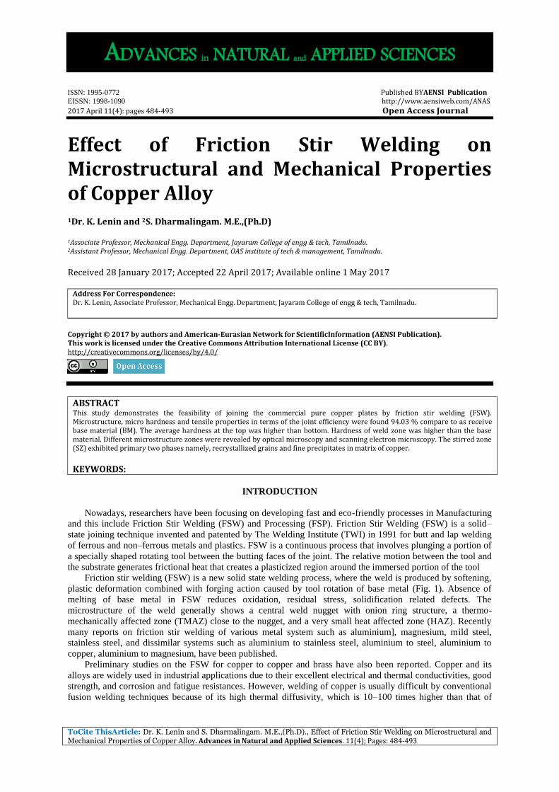
Fig. 2: Microstructure of the welded copper joint: a) base metal, b) nugget zone, c) TMAZ of TMAZ, d) TMAZ
of RS, e) HAZ of AS of , f) HAZ of RS
RESULTS AND DISCUSSION
Welds were obtained according to the experimental design with using filler materials and without filler
materials. All welds were defect free. The intermixing of metals was also found in the welded samples. During
the FSW process, the materials were transported from the advancing side to retreating side behind the pin where
the weld was formed.
7.1 Microstructure:
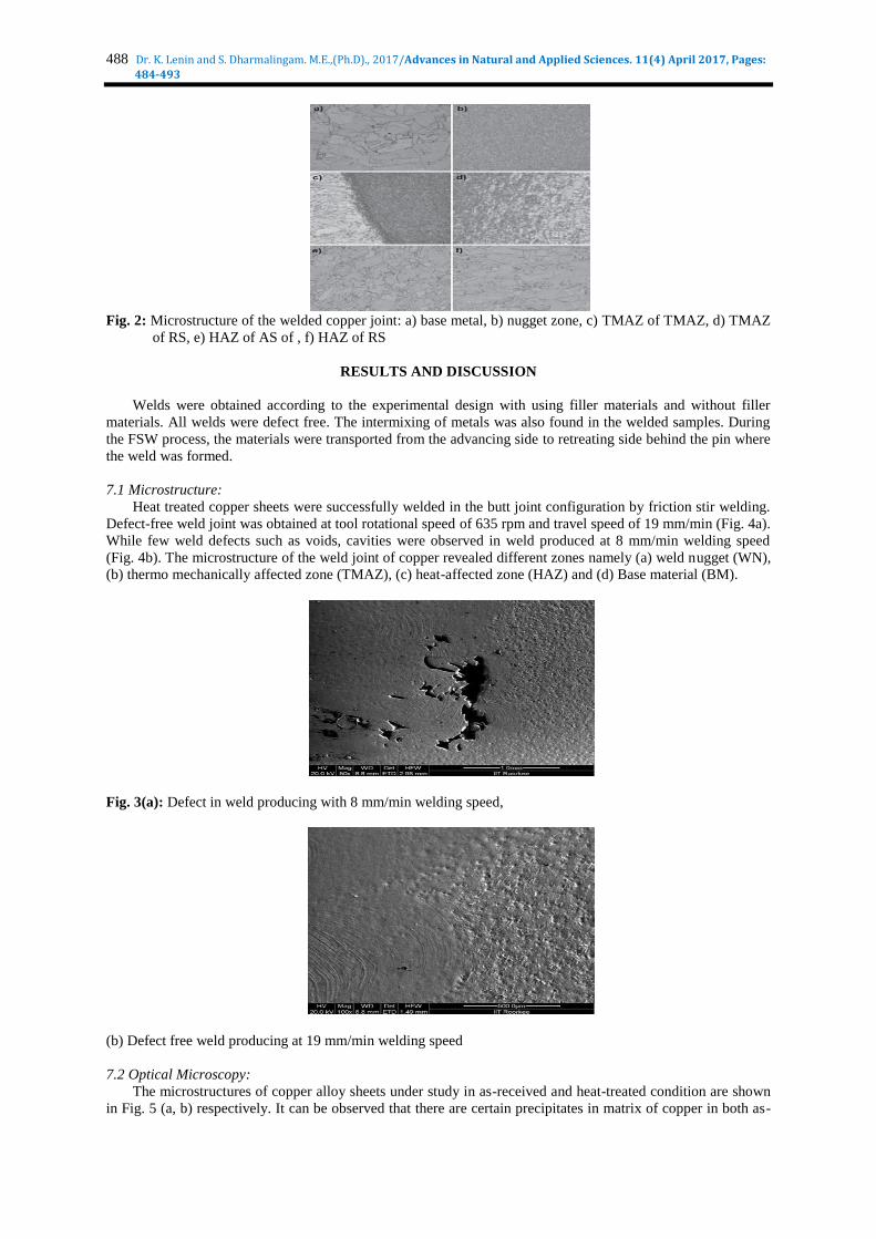
Heat treated copper sheets were successfully welded in the butt joint configuration by friction stir welding.
Defect-free weld joint was obtained at tool rotational speed of 635 rpm and travel speed of 19 mm/min (Fig. 4a).
While few weld defects such as voids, cavities were observed in weld produced at 8 mm/min welding speed
(Fig. 4b). The microstructure of the weld joint of copper revealed different zones namely (a) weld nugget (WN),
(b) thermo mechanically affected zone (TMAZ), (c) heat-affected zone (HAZ) and (d) Base material (BM).
Fig. 3(a): Defect in weld producing with 8 mm/min welding speed,
(b) Defect free weld producing at 19 mm/min welding speed
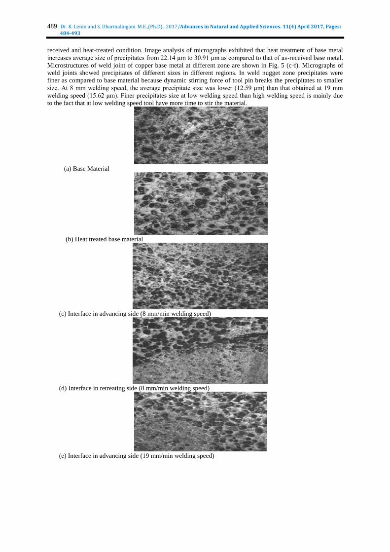
7.2 Optical Microscopy:
The microstructures of copper alloy sheets under study in as-received and heat-treated condition are shown
in Fig. 5 (a, b) respectively. It can be observed that there are certain precipitates in matrix of copper in both as-
489 Dr. K. Lenin and S. Dharmalingam. M.E.,(Ph.D)., 2017/Advances in Natural and Applied Sciences. 11(4) April 2017, Pages:
484-493
received and heat-treated condition. Image analysis of micrographs exhibited that heat treatment of base metal
increases average size of precipitates from 22.14 μm to 30.91 μm as compared to that of as-received base metal.
Microstructures of weld joint of copper base metal at different zone are shown in Fig. 5 (c-f). Micrographs of
weld joints showed precipitates of different sizes in different regions. In weld nugget zone precipitates were
finer as compared to base material because dynamic stirring force of tool pin breaks the precipitates to smaller
size. At 8 mm welding speed, the average precipitate size was lower (12.59 μm) than that obtained at 19 mm
welding speed (15.62 μm). Finer precipitates size at low welding speed than high welding speed is mainly due
to the fact that at low welding speed tool have more time to stir the material.
(a) Base Material
(b) Heat treated base material
(c) Interface in advancing side (8 mm/min welding speed)
(d) Interface in retreating side (8 mm/min welding speed)
(e) Interface in advancing side (19 mm/min welding speed)
490 Dr. K. Lenin and S. Dharmalingam. M.E.,(Ph.D)., 2017/Advances in Natural and Applied Sciences. 11(4) April 2017, Pages:
484-493
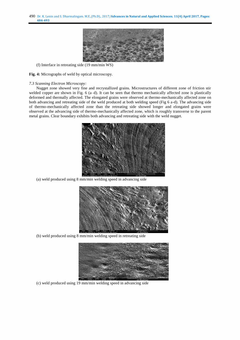
(f) Interface in retreating side (19 mm/min WS)
Fig. 4: Micrographs of weld by optical microscopy.
7.3 Scanning Electron Microscopy:
Nugget zone showed very fine and recrystallized grains. Microstructures of different zone of friction stir
welded copper are shown in Fig. 6 (a–d). It can be seen that thermo mechanically affected zone is plastically
deformed and thermally affected. The elongated grains were observed at thermo-mechanically affected zone on
both advancing and retreating side of the weld produced at both welding speed (Fig 6 a-d). The advancing side
of thermo-mechanically affected zone than the retreating side showed longer and elongated grains were
observed at the advancing side of thermo-mechanically affected zone, which is roughly transverse to the parent
metal grains. Clear boundary exhibits both advancing and retreating side with the weld nugget.
(a) weld produced using 8 mm/min welding speed in advancing side
(b) weld produced using 8 mm/min welding speed in retreating side
(c) weld produced using 19 mm/min welding speed in advancing side
491 Dr. K. Lenin and S. Dharmalingam. M.E.,(Ph.D)., 2017/Advances in Natural and Applied Sciences. 11(4) April 2017, Pages:
484-493
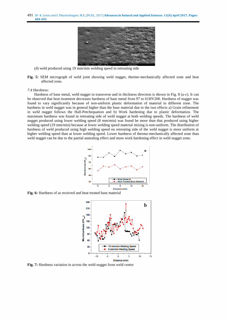
(d) weld produced using 19 mm/min welding speed in retreating side
Fig. 5: SEM micrograph of weld joint showing weld nugget, thermo-mechanically affected zone and heat
affected zone.
7.4 Hardness:
Hardness of base metal, weld nugget in transverse and in thickness direction is shown in Fig. 8 (a-c). It can
be observed that heat treatment decreases hardness of base metal from 97 to 61HV200. Hardness of nugget was
found to vary significantly because of non-uniform plastic deformation of material in different zone. The
hardness in weld nugget was in general higher than the base material due to the two effects a) Grain refinement
in weld nugget follows the Hall-Petchequation and b) Work hardening due to plastic deformation. The
maximum hardness was found in retreating side of weld nugget at both welding speeds. The hardness of weld
nugget produced using lower welding speed (8 mm/min) was found be more than that produced using higher
welding speed (19 mm/min) because at lower welding speed material mixing is non-uniform. The distribution of
hardness of weld produced using high welding speed on retreating side of the weld nugget is more uniform at
higher welding speed than at lower welding speed. Lower hardness of thermo-mechanically affected zone than
weld nugget can be due to the partial annealing effect and more work hardening effect in weld nugget zone.
Fig. 6: Hardness of as received and heat treated base material
Fig. 7: Hardness variation in across the weld nugget from weld centre

492 Dr. K. Lenin and S. Dharmalingam. M.E.,(Ph.D)., 2017/Advances in Natural and Applied Sciences. 11(4) April 2017, Pages:
484-493
Fig. 8: Hardness variation from to bottom of weld nugget at weld centre
7.5 Tensile Test:
Average tensile properties of friction stir weld joints of commercial copper are given in Table IV.
Engineering stress strain diagram for as received and heat treated base metal and friction stir welded sample are
shown in Fig. 9. Heat treatments of base metal decreases yield strength and ultimate tensile strength but
increases ductility. Yield strength decreases from 240.7 MPa to 168.2 MPa while ultimate tensile strength
decreases from 273.2 MPa to 239.3 Mpa. Ductility increases from 33.54 to 34.04%. FSW decreases yield
strength and ultimate tensile strength significantly for weld producing lower welding speed (8 mm/min). The
yield strength decreases from 168.2 MPa to 93.8 MPa while ultimate tensile strength decreases from 239.3 MPa
to 138.8 MPa. The tensile strength of weld joint produced using 19 mm/min welding speed was found higher
than that of base material. At high welding speed the yield strength marginally decreases from 168.2 MPa to
165.4 MPa while ultimate tensile strength increases from 239.3 MPa to 256.9 MPa. Thus the maximum joint
efficiency was found to be 107%.
Fig. 9: Engineering stress-strain diagram of as-received and heat-treated base metal and weld joint produced
using 8 and 19 mm/min Welding speeds
Conclusions:
1. Weld nugget showed finer precipitates than the base metal in both as received and heat treated condition
Advancing side exhibited larger precipitates than the retreating side.
2. Hardness of base metal in as received condition was higher than that in heat treated conditions. Hardness
in weld nugget was found higher than the base metal. The hardness in upper part of nugget at weld centre is
higher than that at the bottom side.
3. Tensile strength and ductility of joints produced using 19mm/min welding speed were found to be higher
than that produced using 8mm/min welding speed.
4. Maximum joint efficiency was 107% in case of the weld produced using 19mm/min welding speed at
635 rpm.
REFERENCES
1. Kallee, S.W., 2001. Friction Stir Welding - How to weld aluminium without melting it, Innovation for new
rail business IMechE, London www.twi.co.uk/j32k/protected
2. Thomas, W.M. and E.D. Nicholas, 1997. Friction stir welding for the transportation industries, Materials &
Design, 18: 269-273.

493 Dr. K. Lenin and S. Dharmalingam. M.E.,(Ph.D)., 2017/Advances in Natural and Applied Sciences. 11(4) April 2017, Pages:
484-493
3. Thomas, W.M., E.D. Nicholas, J.C. Needham, M.G. Nurch, P. Temple-Smith and C. Dawes, 1995. Patents
on Friction Stir Butt Welding, International: PCT/GB92/02203; British:9125978.8; USA: 5460317.
4. Troeger, L.P., E.A. Starke, 2000. Microstructural and mechanical characterization of a superplastic 6xxx
aluminium alloy, Materials Science and Engineering, A277, pp: 102-113.
5. Thomas, W.M., 1993. Improvements Relating to Friction Welding, PCT/GB92/02203, WO 93/10935.
6. Sutton, M.A., B. Yang, A.P. Reynolds, R. Taylor, 2002. Microstructural studies of friction stir welds in
2024-T3 aluminium, Materials Science and Engineering A Issue, 1-2(323): 60-166.
7. Mishra, R.S. and Z.Y. Ma, 2005. Friction stir welding and processing, Materials Science and Engineering,
Reports, 50: 1-78.
8. Dickerson, T.L., J. Przydatek, 2003. Fatigue of friction stir welds in aluminium alloys that contain root
flaws, International Journal of Fatigue, 12(25): 1399-1409.
9. Kallee, S.W., E.D. Nicholas, W.M. Thomas, 2002. Friction Stir Welding: Invention, Innovations and
Industrialization, Berlin, 2002 http://www.twi.co.uk/j32k/.
10. Grant, G.J., 2006. Super plastic forming of aluminium multisheet structures fabricated using friction stir
welding and refill friction stir spot welding, 6th International Symposium on Friction Stir Welding.
11. Kallee, S.W., 2005. Friction stir welding in series production, http://www.twi.co.uk/j32k/ (Last Accessed
12/2006).
12. Khaled, T., 2005. An outsider looks at friction stir welding, federal aviation administration, ANM-112N-
05-06, pp: 1.