EFFECT OF DIFFERENT BUILD ORIENTATION ON...
24
EFFECT OF DIFFERENT BUILD ORIENTATION ON MECHANICAL PROPERTIES OF FIBERGLASS REINFORCED COMPOSITE MUHAMAD KHAIRUL IZZAT BIN MUHAMAD ATAN Thesis submitted in fullfillment of the requirements for the award of the degree of Bachelor of Mechanical Engineering Faculty of Mechanical Engineering UNIVERSITI MALAYSIA PAHANG NOVEMBER 2009
Transcript of EFFECT OF DIFFERENT BUILD ORIENTATION ON...

EFFECT OF DIFFERENT BUILD ORIENTATION ON MECHANICAL PROPERTIES OF FIBERGLASS REINFORCED COMPOSITE
MUHAMAD KHAIRUL IZZAT BIN MUHAMAD ATAN
Thesis submitted in fullfillment of the requirements for the award of the degree of
Bachelor of Mechanical Engineering
Faculty of Mechanical Engineering UNIVERSITI MALAYSIA PAHANG
NOVEMBER 2009

ii
SUPERVISOR’S DECLARATION
We hereby declare that we have checked this project and in our opinion, this project is
adequate in terms of scope and quality for the award of the degree of Bachelor of
Mechanical Engineering.
Signature
Name of Supervisor: NUR AZHANI BT. ABD. RAZAK
Position:
Date:
Signature
Name of Co-Supervisor: AZINUDDIN ZULFAHMI B. MEGAT
Position:
Date:

iii
STUDENT’S DECLARATION
I hereby declare that the work in this project is my own except for quotations and
summaries which have been duly acknowledged. The project has not been accepted for
any degree and is not concurently submitted for award of other degree.
Signature
Name: MUHAMAD KHAIRUL IZZAT B. MUHAMAD ATAN
ID Number: MA06078
Date:

iv
To my beloved father and mother
Mr.Muhamad Atan Bin Awang
Mrs Juhani Binti Othman

v
ACKNOWLEDGEMENTS
In the name of ALLAH, the most gracious, the most merciful. First of all, I am very thankful to ALLAH S.W.T, for giving me strength and
opportunity to finish my Final Year Project 2. With full of His merciful, now I am writing this final report of this project.
I am grateful and would like to express my sincere gratitude to my supervisor
Miss Nur Azhani bt Abd Razak for her germinal ideas, invaluable guidance, continuous encouragement and constant support in making this research possible. She has always impressed me with his outstanding professional conduct. I am truly grateful for his progressive vision about my training in science and engineering, his tolerance of my naïve mistakes, and his commitment to my future career. I also would like to express very special thanks to my co-supervisor Mr. Azinuddin Zulfahmi Bin Megat for his suggestions and co-operation throughout the study. I also sincerely thanks for the time spent proofreading and correcting my many mistakes.
My sincere thanks go to all my labmates and members of the staff of the
Mechanical Engineering Department, UMP, who helped me in many ways and made my stay at UMP pleasant and unforgettable. Many special thanks to them for their excellent co-operation, inspirations and supports during this study.
Last but not least, my special gratitude to my friend for their full support and willingness in solving all problems and tasks. They have given me valuable advices and tips during the preparation of this project. Thank you.

vi
ABSTRACT
This thesis deals with effect of different build orientation on mechanical properties of fibreglass reinforced composite. The objective of this thesis is to investigate the mechanical properties of fibreglass reinforced composite with different build orientation, investigate the relation between fibreglass and polyester resin, and to understand on the mechanical behaviour of fibreglass reinforced composite. Fibreglass is refer to a group of products made from individual glass fibres combined into a variety of forms and act as reinforcing agent. The problem of bonding between fibreglass and the matrix resin affect the strength of the fibreglass reinforced composite and this need to be deals with the study on their mechanical properties by using mechanical experiment test. The test is carried out using tensile test, which all are focusing on investigating mechanical properties on the specimens. Fibreglass reinforced composite is made up by using hand lay-up technique, where different laminate of fibreglass made up by different build orientation of fibreglass which result different strength. The aim of the test is to study on this fibreglass reinforced composite strength and to observed on the mechanical behaviour of this material. It was found that by arranging the fibreglass properly, the stronger the fibreglass reinforced composite be.
vii
ABSTRAK
Tesis ini membentangkan kesan daripada berlainan orientasi binaan kepada fiber-reinforced plastic (FRP). Objektif tesis ini ialah untuk mengkaji sifat mekanikal FRP dengan berlainan orientasi bahan gentian kaca, menyiasat hubung kait antara bahan gentian kaca dengan bahan penguat, serta memahami sifat laku mekanikal bahan tersebut. Plastik yang diperkukuh, atau dikenali sebagai FRP ini mempunyai bahan gentian kaca didalamnya. Masalah yang timbul di antara ikatan gentian kaca dan bahan penguat resin menjejaskan kekuatan bahan ini, dan tesis ini membincangkan sifat mekanikal bahan ini dengan cara menjalankan eksperimen. Eksperimen yang dijalankan iaitu, ‘tensile test’ memfokuskan kajian tentang sifat-sifat mekanikal yang ditunjukkan oleh specimen. FRP ini dihasilkan sendiri menggunakan tangan melalui teknik ‘tindih dan tindih’, yang mana orientasi bahan gentian kaca yang berbeza, akhirnya mempunyai kekuatan berlainan. Tujuan dijalankan eksperimen ini ialah bagi mengukur kekuatan bahan dan melihat sendiri perubahan yang berlaku terhadap FRP ini apabila dikenakan daya. Ianya diketahui bahawa menyusun bahan gentian kaca dengan betul, maka makin kuat bahan tersebut.

viii
TABLE OF CONTENTS
Page
SUPERVISOR’S DECLARATION ii
STUDENT’S DECLARATION iii
ACKNOWLEDGEMENTS v
ABSTRACT vi
ABSTRAK vii
TABLE OF CONTENTS viii
LIST OF TABLES xi
LIST OF FIGURES xii
LIST OF SYMBOLS xiv
LIST OF ABBREVIATIONS xv
CHAPTER 1 INTRODUCTION
1.1 Background of Study 1
1.3 Objectives of Study 2
1.3 Scopes of Project 2
1.4 Problem Statement 2
CHAPTER 2 LITERATURE REVIEW
2.1 Introduction 3
2.2 Composite 3
2.2.1 Definition of composite materials 4 2.2.2 Classification of composite types 5
2.3 Polymer-matrix composites (PMCs) 6
2.4 Glass fibre-reinforced polymer composites (GFRP) 7
2.4.1 Applications 8 2.4.2 Physical properties 9
2.5 Fibreglass 9
2.5.1 Formation 10 2.5.2 Properties 11

ix
2.5.3 Uses 11
2.6 Polymer 12
2.6.1 Thermoplastic 12 2.6.2 Thermoset 12
2.7 Unsaturated Polyester 13
2.7.1 Mechanical properties 14 2.7.2 Uses 14
2.8 Experiment Method 15
2.8.1 Tensile Test 15
2.9 Measuring instrumentation 16
2.9.1 Tensile Machine 16
CHAPTER 3 DURABILITY ASSESSMENT METHODS
3.1 Introduction 18
3.2 General Experiment Procedure 19
3.3 Materials 20
3.4 Mould Preparation 20
3.5 Experiment Design 21
3.5.1 Build Orientation 21
3.6 Hand lay-up Process 22
3.7 Specimen preparation 23
3.8 Tensile Test 24
CHAPTER 4 RESULTS AND DISCUSSION
4.1 Introduction 26
4.2 Data 26
4.3 Tensile test 26
CHAPTER 5 CONCLUSION AND RECOMMENDATIONS
5.1 Conclusion 36
5.2 Recommendations for the Future Research 37

x
REFERENCES 38
APPENDICES 40
A1 Project Gantt Chart for FYP I 40
A2 Project Gantt Chart for FYP II 41
B A sample of fracture specimen after given tensile test for (a) 90 °,
(b) random and (c) 0 ° orientation
42

xi
LIST OF TABLES
Table No. Title Page 3.1 Table of data for tensile test (laminates with 90°, 0º and random
orientation of fibreglass used) 24
3.2 Table of Young’s Modulus, E (MPa) for 0º, random and 90º
orientation of fibreglass 25
4.1 Result of tensile test (Fibreglass with 0º orientation) 28 4.2 Result of tensile test (Fibreglass with random orientation) 30 4.3 Result of tensile test (Fibreglass with 90º orientation) 32 4.4 Table of Young’s Modulus, E (MPa) for 0º, random and 90º
orientation 35
4.5 Table of all average value in tensile test 36

xii
LIST OF FIGURES
Figure No. Title Page 2.1 Matrix phase 5 2.2 Stress –Strain curves of composite constituents 6 2.3 Grouping of polymer-matrix composites 7 2.4 Bundle of fibreglass 10 2.5 (a) Thermoplastic ,(b) Thermoset 13 2.6 Unsaturated polyester. Tensile strength versus % and length of
fibre 14
2.7 Unsaturated polyester. Notched impact versus % and length of
fibre 14
2.9 Stress-strain diagram 16 2.10 Universal Tensile Machine 17 3.1 Open Mould 20 3.2 (a) 90 (b) 0 and (c) random 21 3.3 The size of specimen according to ASTM D3039 of 90°
orientation 21
3.4 Hand lay-up 22 3.5 The dimension of tensile specimen according to ASTM D3039 25 4.1 Sample condition (break) after given load of 90° orientation of
fibreglass 28
4.2 Graph of load versus displacement using fibreglass with 0º
orientation 29
4.3 Graph of stress versus strain using fibreglass with 0º orientation 29 4.4 Graph of load versus displacement using fibreglass with random
orientation 31
4.5 Graph of stress versus strain using fibreglass with random
orientation 31
,° ,°

xiii
4.6 Graph of load versus displacement using fibreglass with 90º
orientation 33
4.7 Graph of stress versus strain using fibreglass with 90º orientation 33 4.8 A piece of damaged specimen (no necking occurred) 34
xiv
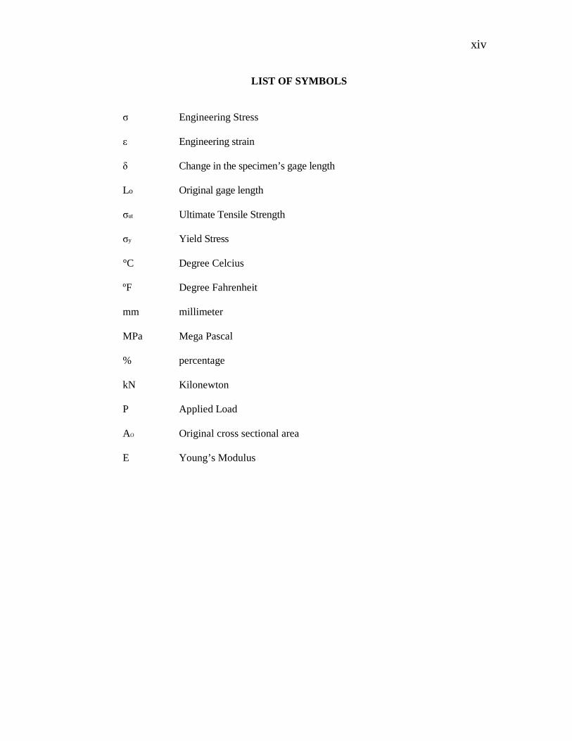
LIST OF SYMBOLS
σ Engineering Stress ε Engineering strain δ Change in the specimen’s gage length Lo Original gage length σut Ultimate Tensile Strength σy Yield Stress °C Degree Celcius ºF Degree Fahrenheit mm millimeter MPa Mega Pascal % percentage kN Kilonewton P Applied Load AO Original cross sectional area E Young’s Modulus

xv
LIST OF ABBREVIATIONS
GFRP Glass Fiber Reinforced Polymer PMCs Polymer Matrix Composites CFRP Carbon Fiber Reinforced Polymer ASTM American Society for Testing and Materials FRP Fiber Reinforced Plastic GRE Glass Fibre Reinforced Epoxy R&D Research and Development RF Radio Frequency UTS Ultimate Tensile Strength PVC Polyvinyl Chloride PE Polyethylene PP Polypropylene UP Unsaturated Polyester PURs Polyurethenas

1
CHAPTER 1
INTRODUCTION
1.1 BACKGROUND OF STUDY
The term composite could mean almost anything if taken at face value, since all
materials are composed of dissimilar subunits if examined at close enough detail. But in
modern materials engineering, the term usually refers to a “matrix" material that is
reinforced with fibres. For instance, the term “FRP" (for Fibre Reinforced Plastic)
usually indicates a thermosetting polyester matrix containing glass fibres, and this
particular composite has the lion's share of today's commercial market.
Many composites used today are at the leading edge of materials technology,
with performance and costs appropriate to ultra demanding applications such as
spacecraft. But heterogeneous materials combining the best aspects of dissimilar
constituents have been used by nature for millions of years. Ancient society, imitating
nature, used this approach as well: the Book of Exodus speaks of using straw to
reinforce mud in brick making, without which the bricks would have almost no strength.
The fibres used in modern composites have strengths and stiffness far above those of
traditional bulk materials. The high strengths of the glass fibres are due to processing
that avoids the internal or surface flaws which normally weaken glass, and the strength
and stiffness of the polymeric aramid fibre is a consequence of the nearly perfect
alignment of the molecular chains with the fibre axis. Of course, these materials are not
generally usable as fibres alone, and typically they are impregnated by a matrix material
that acts to transfer loads to the fibres, and also to protect the fibres from abrasion and
environmental attack. The matrix dilutes the properties to some degree, but even so very
high specific (weight-adjusted) properties are available from these materials. Metal and

2
glass are available as matrix materials, but these are currently very expensive and
largely restricted to R&D laboratories. Polymers are much more commonly used, with
unsaturated styrene-hardened polyesters having the majority of low-to-medium
performance applications and epoxy or more sophisticated thermosets having the higher
end of the market.
1.2 OBJECTIVES OF STUDY
i. To investigate the mechanical properties of fibreglass reinforced composite with
different build orientation.
ii. To determine the mechanical strength (tensile strength) of fibreglass reinforced
composite.
1.3 SCOPES OF PROJECT
i. To prepare the sample specimen based on different orientation of fibreglass
which are 0°, 90° and random.
ii. To examine the strength of the specimen by tensile test method using Universal
Testing Machine.
iii. To determine the specimen with the highest ultimate strength.
1.4 PROBLEM STATEMENT
Composites usually used in high technology application because of their
hardness and strength. However, fibre orientation in composite will affect the composite
strength in which different build of orientation will be used. Stress distribution will be
varied according to the orientation of fibre.

3
CHAPTER 2
LITERATURE REVIEW
2.1 INTRODUCTION
In this chapter, the importance and application of the composite materials at
several sectors will be discussed. This chapter will inquired into the general properties
of the components that commonly used to produce polymer composite materials which
are fibre glass, polyester and epoxy. Through this chapter, the details of the composite
materials can be understood in depth. The roles of build orientation in mechanical
properties of the composite materials also can be studied deeply. Hence, a suitable
composition of fibre and resin can be investigated to produce composite materials with
better performance.
2.2 COMPOSITE
Practically everything is a composite material in some sense. For example, a
common piece of metal is a composite (polycrystal) of many grains (or single crystals).
A composite material:
Consists of two or more physically and/or chemically distinct, suitably arranged
or distributed phases, with an interface separating them. It has characteristics
that are not depicted by any of the components in isolation (D. Calllister
William, 1985).
Most commonly, composite materials have a bulk phase, which is continuous,
called the matrix, and one dispersed, non-continuous, phase called the reinforcement,
which is usually harder and stronger.

4
The concept of composite materials is ancient: to combine different materials to
produce a new material with performance unattainable by the individual constituents.
An example is adding straw to mud for building stronger mud walls. Some more recent
examples, but before engineered materials became prominent, are carbon black in
rubber, steel rods in concrete, cement/asphalt mixed with sand, fibreglass in resin etc. In
nature, examples abound: a coconut palm leaf, cellulose fibres in a lignin matrix
(wood), collagen fibres in an apatite matrix (bone) etc.
The essence of the concept of composites is this: the bulk phase accepts the load
over a large surface area, and transfers it to the reinforcement, which being stiffer,
increases the strength of the composite. The significance here lies in that there are
numerous matrix materials and as many fibre types, which can be combined in
countless ways to produce just the desired properties.
Most research in engineered composite materials has been done since 1965.
Today, given the most efficient design, of say an aerospace structure, a boat or a motor,
we can make a composite material that meets or exceeds the performance requirements.
Most of the savings are in weight and cost. These are measured in terms of ratios such
as stiffness/weight, strength/weight, etc.
2.2.1 Definition of composite materials
The definition of a composite depends on the context. Composites are materials
that utilize the combination of its constituents to increase a desired performance
characteristic. Using this definition, the pearlitic steels may be thought of as a
composite material formed by the combination of ferrite and cementite phases in
alternating lamellae. The hard, brittle cementite combines with the soft, ductile ferrite to
form a composite that has reasonably high strength along with some ductility. The
present discussion will not focus on these naturally occurring composites, but rather
those that are man made. These have phases that are chemically dissimilar and have a
definite interface. Composites such as these have been developed to improve the
strength, stiffness, and toughness of available materials.

5
A composite material may consist of many materials put together in many
different ways. A simple example is material consisting of two phases. The matrix
phase is continuous and forms the shape in which the dispersed phase acts as a
constituent. There are different types of dispersed phase. It can be of a particle nature,
meaning each particle is equiaxed, or it can be of a fibrous nature, where the dispersed
phase is a filament. The type of dispersed phase, its orientation (for the fibrous type),
size, relative amounts, and material properties will all affect the properties of the overall
material.
2.2.2 Classification of composite types
Composite are classified by the geometry of the reinforcement
Figure 2.1: Matrix phase
The matrix phase is an essential part of the composite composition. Matrix
materials can consist of a metal, polymer or a ceramic. Polymer matrices are the most
common followed by metal and ceramics. The matrix phase has several important
functions with respect to fibreous reinforced composites. The matrix acts to hold all
reinforcements together thereby allowing the applied force to transmit to the
reinforcement (L. Lehman Richard, 1999).
The matrix, due to its inherent ductility, does not carry a significant portion of
the applied load. Instead the load is transmitted to the fibres. In order for this to occur
Matrix Phase
Polymer Ceramic Metal

the composite constituents must have a high
seen in Figure 2 below.
Figure 2.
Other functions of the matrix include protection of the composite
damage and to prevent crack propagation within the material. Adhesive bonding forces
between the fibres and the
materials. This separation of the
force between the two phases must be large to prevent this
forces play an important role in the overall load carrying characteristics of
2.3 POLYMER-MATRIX COMPOSITES
i. Matrix made from a polymer resin
ii. Fibres act as reinforcement mechanism
iii. Most widely used of all composites
iv. Low cost / Easily manufactured
composite constituents must have a high fibre to matrix strength ratio. This can be
2.2: Stress –Strain curves of composite constituents
Other functions of the matrix include protection of the composite
prevent crack propagation within the material. Adhesive bonding forces
s and the matrix are essential in preventing separation of the two
materials. This separation of the fibre from the matrix is called “pull-out”. The bonding
en the two phases must be large to prevent this from occurring. Bonding
forces play an important role in the overall load carrying characteristics of
MATRIX COMPOSITES (PMCs)
Matrix made from a polymer resin
reinforcement mechanism
Most widely used of all composites
Low cost / Easily manufactured
6
io. This can be
Strain curves of composite constituents
Other functions of the matrix include protection of the composite fibres from
prevent crack propagation within the material. Adhesive bonding forces
matrix are essential in preventing separation of the two
out”. The bonding
from occurring. Bonding
the material.

7
Polymer-matrix composites (PMCs) can be grouped in three different categories.
The grouping is based to a large degree on the type of fibre reinforcement utilized in the
composite matrix. A variety of polymers may be used for each type of PMC. The three
groups are glass fibre-reinforced polymer (GFRP), carbon fibre-reinforced polymer
(CFRP), and aramid fibre-reinforced polymer composites (Peter Morgan, 2005). This
grouping is shown in Figure 3.
Figure 2.3: Grouping of polymer-matrix composites
2.4 GLASS FIBRE-REINFORCED POLYMER COMPOSITES (GFRP)
Glass fibre-reinforced polymer composites (GFRP), commonly known as
fibreglass composites are the most widely used of all composites. GFRP is fibre-
reinforced plastic made of a plastic reinforced by fine fibres made of glass . The plastic
is thermosetting, most often polyester or vinylester, but other plastics, like epoxy
(GRE), are also used.
PMCs
Carbon Fiber-Reinforced Polymer
(CFRP)
“Carbon Fiber”
Carbon Fiber-Reinforced Polymer
(CFRP)
Carbon Fiber-Reinforced Polymer
(CFRP)
“Carbon Fiber” “Carbon Fiber”

8
2.4.1 Applications
GFRP is an immensely versitile material which combines lightweight with
inherent strength to provide a weather resistant finish, with a variety of surface texture
and an unlimited colour range available (Loewenstein, 1973).
GFRP was developed in the UK during the Second World War as a replacement
for the molded plywood used in aircraft radomes (GFRP being transparent to
microwaves). Its first main civilian application was for building of boats, where it
gained acceptance in the 1950s. Its use has broadened to the automotive and sport
equipment sectors, although its use there is being taken over by carbon fibre which
weighs less per given volume and is stronger both by volume and by weight. GFRP uses
also include hot tubs, pipes for drinking water and sewers, office plant display
containers and flat roof systems.
Advanced manufacturing techniques such as pre-pregs and fibre rovings extend
the applications and the tensile strength possible with fibre-reinforced plastics.
GFRP is also used in the telecommunications industry for shrouding the visual
appearance of antennas, due to its RF permeability and low signal attenuation
properties. It may also be used to shroud the visual appearance of other equipment
where no signal permeability is required, such as equipment cabinets and steel support
structures, due to the ease with which it can be molded, manufactured and painted to
custom designs, to blend in with existing structures or brickwork. Other uses include
sheet form made electrical insulators and other structural components commonly found
in the power industries (Dominick V Rosato, 2004).

9
2.4.2 Physical properties
The properties of GFRP composites are measured the same way that traditional
materials are measured so that comparisons can be made for evaluation. Typical
measurements include:
Impact Strength –There are two primary impact tests; one is called IZOD impact and the
other is called Charpy impact. IZOD impact measures the energy required to fracture or
break a material when it is struck on its edge. Charpy impact measures the energy
required to damage or puncture a material when it is struck on its front surface.
Tensile Strength– Measures how much of a load a material can take before it fractures
or breaks when it is in the process of being stretched (Yunkai Lu, 2002).
2.5 FIBREGLASS
Fibreglass, (also called fibreglass and glass fibre), is material made from
extremely fine fibres of glass. It is used as a reinforcing agent for many polymer
products; the resulting composite material, properly known as fibre-reinforced plastic
(FRP) or glassfibre-reinforced plastic (GFRP), is called "fibreglass" in popular usage.
Glassmakers throughout history have experimented with glass fibres, but mass
manufacture of fibreglass was only made possible with the invention of finer machine
tooling. In 1893, Edward Drummond Libbey exhibited a dress at the World's
Columbian Exposition incorporating glass fibres with the diameter and texture of silk
fibres. This was first worn by the popular stage actress of the time Georgia Cayvan.
What is commonly known as "fibreglass" today, however, was invented in 1938
by Russell Games Slayter of Owens-Corning as a material to be used as insulation. It is
marketed under the trade name Fibreglas, which has become a genericized trademark. A
somewhat similar, but more expensive technology used for applications requiring very
high strength and low weight is the use of carbon fibre.