Effect of cutting on surface hardness and residual ...
10
Research paper 80 © Copyright by International OCSCO World Press. All rights reserved. 2012 VOLUME 55 ISSUE 1 November 2012 of Achievements in Materials and Manufacturing Engineering of Achievements in Materials and Manufacturing Engineering Effect of cutting on surface hardness and residual stresses for 12Mn austenitic steel M. Cebron a,b, *, F. Kosel a , J. Kopac a a Faculty of Mechanical Engineering, University of Ljubljana, Askerceva 6, 1000 Ljubljana, Slovenia b Hidria Rotomatika d.o.o., Spodnja Kanomlja 23, 5281 Spodnja Idrija, Slovenia * Corresponding e-mail address: [email protected] Received 15.09.2012; published in revised form 01.11.2012 Manufacturing and processing ABSTRACT Purpose: Austenitic steels are known for their high impact toughness and resistance against abrasive wear, yet their machining is difficult and limits their application. Since surface conditions resulting from production strongly affect the performance of finished products, any information linking the machining process to the mechanical properties of the surface is useful not only in production but also in the design phase of the product. Design/methodology/approach: The state of the cutting zone was researched using a quick-stop device for suddenly stopping the cutting process and so retaining the mechanical conditions developed during machining. Residual stresses were measured using X-ray diffractometry, while the standard Vickers micro-indentation hardness test was used for determining the material hardness in the cutting zone. Findings: It was confirmed that the analysed material hardens substantially during machining and that the wear of cutting tools can be related both to this phenomenon and to the material structure after heat treatment. Furthermore, it was found that inadequate machining conditions can lead to tensile stresses that alone can initiate cracks in the surface layer even before the material is additionally loaded. Research limitations/implications: Since measurements of temperature in the cutting zone were not performed, the effect of temperature on the final mechanical properties of the surface can only be estimated. The dislocation theory of hardening is briefly explained, while actual research of dislocations is limited. Since the orthogonal cutting process involves substantial plastic deformation, the study of dislocation motion in the cutting area could be of interest. Practical implications: The main reasons why highly hardening materials require an accurate assessment of the cutting conditions are outlined. It is shown that an apt choice of cutting conditions has a favourable influence both on the condition of the surface after cutting and on the tool life. Originality/value: This paper presents an account of some of the difficulties that are associated with machining austenitic and other highly hardening materials. Since the detailed composition of the material and all the important machining parameters are listed, the results presented can also be useful for checking or calibrating numerical models of the cutting process. Keywords: Machining; Mechanical properties; Austenitic steel; Hardening phenomena Reference to this paper should be given in the following way: M. Cebron, F. Kosel, J. Kopac, Effect of cutting on surface hardness and residual stresses for 12Mn austenitic steel, Journal of Achievements in Materials and Manufacturing Engineering 55/1 (2012) 80-89.
Transcript of Effect of cutting on surface hardness and residual ...

Research paper80 © Copyright by International OCSCO World Press. All rights reserved. 2012
VOLUME 55
ISSUE 1
November
2012of Achievements in Materialsand Manufacturing Engineeringof Achievements in Materialsand Manufacturing Engineering
Effect of cutting on surface hardness and residual stresses for 12Mn austenitic steel
M. Cebron a,b,*, F. Kosel a, J. Kopac a a Faculty of Mechanical Engineering, University of Ljubljana, Askerceva 6, 1000 Ljubljana, Slovenia b Hidria Rotomatika d.o.o., Spodnja Kanomlja 23, 5281 Spodnja Idrija, Slovenia * Corresponding e-mail address: [email protected]
Received 15.09.2012; published in revised form 01.11.2012
Manufacturing and processing
AbstrActPurpose: Austenitic steels are known for their high impact toughness and resistance against abrasive wear, yet their machining is difficult and limits their application. Since surface conditions resulting from production strongly affect the performance of finished products, any information linking the machining process to the mechanical properties of the surface is useful not only in production but also in the design phase of the product.Design/methodology/approach: The state of the cutting zone was researched using a quick-stop device for suddenly stopping the cutting process and so retaining the mechanical conditions developed during machining. Residual stresses were measured using X-ray diffractometry, while the standard Vickers micro-indentation hardness test was used for determining the material hardness in the cutting zone.Findings: It was confirmed that the analysed material hardens substantially during machining and that the wear of cutting tools can be related both to this phenomenon and to the material structure after heat treatment. Furthermore, it was found that inadequate machining conditions can lead to tensile stresses that alone can initiate cracks in the surface layer even before the material is additionally loaded.Research limitations/implications: Since measurements of temperature in the cutting zone were not performed, the effect of temperature on the final mechanical properties of the surface can only be estimated. The dislocation theory of hardening is briefly explained, while actual research of dislocations is limited. Since the orthogonal cutting process involves substantial plastic deformation, the study of dislocation motion in the cutting area could be of interest.Practical implications: The main reasons why highly hardening materials require an accurate assessment of the cutting conditions are outlined. It is shown that an apt choice of cutting conditions has a favourable influence both on the condition of the surface after cutting and on the tool life.Originality/value: This paper presents an account of some of the difficulties that are associated with machining austenitic and other highly hardening materials. Since the detailed composition of the material and all the important machining parameters are listed, the results presented can also be useful for checking or calibrating numerical models of the cutting process.Keywords: Machining; Mechanical properties; Austenitic steel; Hardening phenomena
Reference to this paper should be given in the following way: M. Cebron, F. Kosel, J. Kopac, Effect of cutting on surface hardness and residual stresses for 12Mn austenitic steel, Journal of Achievements in Materials and Manufacturing Engineering 55/1 (2012) 80-89.
1. Introduction High-alloy manganese austenitic steels prove to be exceedingly
difficult to machine by cutting. Hardening during shear deformation is so strong that only a careful selection of high quality tools and exactly defined working conditions allow the cutting process to be successful. An improvement in machinability can also be achieved with the right heat treatment before cutting. Investigations of the hardening phenomena in the cutting zone and the analysis of the tool and work piece surface help to identify the reasons for high wear rates and failure of the cutting tool [1].
During cutting, even when the cutting depth is small, severe shear deformations cause a marked increase in hardness in the cut-off material and a considerably hardened layer is generated on the machined surface. This has a very negative influence on tool life and causes additional difficulties if the surface is to be further machined.
Residual stresses are generally the result of a non-homogeneous plastic deformation and are in a state of equilibrium if there are no external loads. Tensile normal stresses in the surface layer must therefore be counterbalanced by compressive stresses in the bulk and vice versa. Usually the absolute value of residual stresses is high close to the surface and decreases continuously with increasing depth [4]. Fatigue cracks commonly nucleate in the surface layer and subsequently propagate into the bulk of the material. In un-suitable working conditions tensile residual stresses are induced in the surface layer, which facilitates the formation of micro-cracks with negative consequences on the fatigue life of the product. This paper shows that residual stresses after machining can in some cases exceed the ultimate strength of the material and provoke superficial micro-cracks even before the part is additionally loaded.
For dynamically loaded machine parts it is crucial that compressive residual stresses in the surface layer are ensured. The total stresses are the sum of residual stresses and load stresses induced by the action of external forces and moments. Therefore to ensure a long life of the machine part, knowledge of residual stresses and how to adjust their size and distribution by proper selection of appropriate production technology and parameters is highly important. A long list of studies on this topic is found in [3]. Besides on crack initiation, residual stresses also have an effect on stress-induced corrosion and can assist or inhibit processes of phase transformations.
A large number of analytical, numerical and experimental research studies can be found about the effect of cutting parameters on surface conditions and their consequences on durability of machined parts. The main goal of these studies is to efficiently correlate the type of machining and the process parameters to the final mechanical state of the surface.
However, analytical models of plastic deformation and hardening in orthogonal cutting are quite rare and often over-simplified. An example of such study can be found in [1], where a model valid for a sphere is used to predict the depth of yielding from the radius of the cutting edge and the applied cutting force. The vast majority of existing studies are experimental. In [4] El-Axir modelled the residual stress profile as a fifth degree polynomial of distance from the machined surface. He proposes that the coefficients of the polynomial are functions of tree machining parameters: tensile strength of the material being cut, cutting speed and feed rate. D.A. Lados [10] studied the effect of
residual stresses on fatigue crack growth of casted AlSi alloys. The effect of machining parameters on fatigue behaviour of test specimens was studied by H.K. Akyildiz [15], however in this case the direct link between machining parameters and surface conditions was not investigated. In [14] A. Dalloz performed a numerical and experimental investigation on the effect of cutting on ductility of a dual phase steel. It was found that fracture in this case occurred consequently to void nucleation and coalescence at phase interfaces.
Among various numerical techniques which can be used for studying metal cutting, the finite element method is the most widely applied. The models employed are usually based on earlier studies, experimental findings and experiences of the researchers. In the first phase of a typical numerical investigation the mechanical and metallographic properties of non-machined material are investigated. This is followed by an experimental overview of the cutting process, after which the properties of the material in the machined state are measured. A numerical model based on experi-mental findings is then proposed and tested. If necessary, in the final step the numerical model is calibrated in order to achieve a good agreement between experimental and numerical results [14].
Complexities in numerical studies of the cutting process are mainly due to: large strains and high strain-rates in the primary shear zone, work-hardening and temperature softening of the material, friction and the related heat generation between the chip and the tool along the secondary shear zone.
Shet [11] simulated the orthogonal cutting process with focus on the residual stress and strain fields in the finished workpiece. Chip separation was modelled using the nodal release technique based on critical stress, while friction in the secondary shear zone was modelled by a modified Coulomb friction law. P. Escalona [5] studied the influence of stress, strain and temperature on surface roughness. Experimentally determined cutting forces were used to validate the numerical simulation. A numerical examination focused on the temperature conditions in the cutting zone was presented by Grzesik in [21]. In most numerical studies it is found that a correct description of shear deformation and chip formation in the cutting zone is essential for developing consistent numerical models of cutting.
1.1. Orthogonal cutting model
Before the industrial revolution it was supposed that during metal cutting a crack propagated in front of the cutting edge along the direction of tool movement, which led to the formation of the chip. Since then this notion has been dismissed and today it is well established that the cutting process involves only shear plastic deformation of the material in a shear zone in front of the cutting edge.
The characteristics of metal cutting are most easily presented on the classic orthogonal model (Fig. 1) since this is a two dimensional presentation, even though real cutting procedures are mostly complex 3-D operations. According to this model the material in front of the cutting zone is undeformed until it passes through the shear plane AB oriented at an angle to the surface.
When passing through this plane (also called primary shear zone), the material above the set cutting depth h deforms instan-taneously in the shear direction of the plane, thus forming a chip

81READING DIRECT: www.journalamme.org
Manufacturing and processing
1. Introduction High-alloy manganese austenitic steels prove to be exceedingly
difficult to machine by cutting. Hardening during shear deformation is so strong that only a careful selection of high quality tools and exactly defined working conditions allow the cutting process to be successful. An improvement in machinability can also be achieved with the right heat treatment before cutting. Investigations of the hardening phenomena in the cutting zone and the analysis of the tool and work piece surface help to identify the reasons for high wear rates and failure of the cutting tool [1].
During cutting, even when the cutting depth is small, severe shear deformations cause a marked increase in hardness in the cut-off material and a considerably hardened layer is generated on the machined surface. This has a very negative influence on tool life and causes additional difficulties if the surface is to be further machined.
Residual stresses are generally the result of a non-homogeneous plastic deformation and are in a state of equilibrium if there are no external loads. Tensile normal stresses in the surface layer must therefore be counterbalanced by compressive stresses in the bulk and vice versa. Usually the absolute value of residual stresses is high close to the surface and decreases continuously with increasing depth [4]. Fatigue cracks commonly nucleate in the surface layer and subsequently propagate into the bulk of the material. In un-suitable working conditions tensile residual stresses are induced in the surface layer, which facilitates the formation of micro-cracks with negative consequences on the fatigue life of the product. This paper shows that residual stresses after machining can in some cases exceed the ultimate strength of the material and provoke superficial micro-cracks even before the part is additionally loaded.
For dynamically loaded machine parts it is crucial that compressive residual stresses in the surface layer are ensured. The total stresses are the sum of residual stresses and load stresses induced by the action of external forces and moments. Therefore to ensure a long life of the machine part, knowledge of residual stresses and how to adjust their size and distribution by proper selection of appropriate production technology and parameters is highly important. A long list of studies on this topic is found in [3]. Besides on crack initiation, residual stresses also have an effect on stress-induced corrosion and can assist or inhibit processes of phase transformations.
A large number of analytical, numerical and experimental research studies can be found about the effect of cutting parameters on surface conditions and their consequences on durability of machined parts. The main goal of these studies is to efficiently correlate the type of machining and the process parameters to the final mechanical state of the surface.
However, analytical models of plastic deformation and hardening in orthogonal cutting are quite rare and often over-simplified. An example of such study can be found in [1], where a model valid for a sphere is used to predict the depth of yielding from the radius of the cutting edge and the applied cutting force. The vast majority of existing studies are experimental. In [4] El-Axir modelled the residual stress profile as a fifth degree polynomial of distance from the machined surface. He proposes that the coefficients of the polynomial are functions of tree machining parameters: tensile strength of the material being cut, cutting speed and feed rate. D.A. Lados [10] studied the effect of
residual stresses on fatigue crack growth of casted AlSi alloys. The effect of machining parameters on fatigue behaviour of test specimens was studied by H.K. Akyildiz [15], however in this case the direct link between machining parameters and surface conditions was not investigated. In [14] A. Dalloz performed a numerical and experimental investigation on the effect of cutting on ductility of a dual phase steel. It was found that fracture in this case occurred consequently to void nucleation and coalescence at phase interfaces.
Among various numerical techniques which can be used for studying metal cutting, the finite element method is the most widely applied. The models employed are usually based on earlier studies, experimental findings and experiences of the researchers. In the first phase of a typical numerical investigation the mechanical and metallographic properties of non-machined material are investigated. This is followed by an experimental overview of the cutting process, after which the properties of the material in the machined state are measured. A numerical model based on experi-mental findings is then proposed and tested. If necessary, in the final step the numerical model is calibrated in order to achieve a good agreement between experimental and numerical results [14].
Complexities in numerical studies of the cutting process are mainly due to: large strains and high strain-rates in the primary shear zone, work-hardening and temperature softening of the material, friction and the related heat generation between the chip and the tool along the secondary shear zone.
Shet [11] simulated the orthogonal cutting process with focus on the residual stress and strain fields in the finished workpiece. Chip separation was modelled using the nodal release technique based on critical stress, while friction in the secondary shear zone was modelled by a modified Coulomb friction law. P. Escalona [5] studied the influence of stress, strain and temperature on surface roughness. Experimentally determined cutting forces were used to validate the numerical simulation. A numerical examination focused on the temperature conditions in the cutting zone was presented by Grzesik in [21]. In most numerical studies it is found that a correct description of shear deformation and chip formation in the cutting zone is essential for developing consistent numerical models of cutting.
1.1. Orthogonal cutting model
Before the industrial revolution it was supposed that during metal cutting a crack propagated in front of the cutting edge along the direction of tool movement, which led to the formation of the chip. Since then this notion has been dismissed and today it is well established that the cutting process involves only shear plastic deformation of the material in a shear zone in front of the cutting edge.
The characteristics of metal cutting are most easily presented on the classic orthogonal model (Fig. 1) since this is a two dimensional presentation, even though real cutting procedures are mostly complex 3-D operations. According to this model the material in front of the cutting zone is undeformed until it passes through the shear plane AB oriented at an angle to the surface.
When passing through this plane (also called primary shear zone), the material above the set cutting depth h deforms instan-taneously in the shear direction of the plane, thus forming a chip
1. Introduction
1.1. Orthogonal cutting model

Research paper82
Journal of Achievements in Materials and Manufacturing Engineering
M. Cebron, F. Kosel, J. Kopac
Volume 55 Issue 1 November 2012
of removed material. The tool in orthogonal cutting presents only two geometrical elements: the rake and the clearance angle, marked and respectively.
Fig. 1. The classic orthogonal cutting model
Fig. 2. Geometrical characteristics of the cutting process Table 1. Geometrical parameters presented in Fig. 1 and Fig. 2 [1]
a r h v 1.5 mm 0.8 mm 6° 15° Adj. Adj. 6° -6°
Fig. 2 together with Fig. 1 and Table 1 presents all the
relevant geometrical characteristics of the turning process used in this investigation. All feed rates h are given as a value per passing of the tool (in the case of turning per revolution).
2. Structure of the investigated material
The ability of austenitic steel to harden rapidly makes it par-ticularly suitable for applications in which wear and damage of the components take place by continued abrasion and impact loads. Usually a fully austenitic structure, essentially free of carbides, is desired although this is not always attainable for massive sections. If the surface pressure is not high enough to cause hardening but abrasive wear still occurs, the performance of austenitic steels is worse than that of suitably hardened steels.
The grade of the studied material is GX120Mn12 according to DIN12513. The exact chemical composition is given in Table 2. Table 2. Measured chemical composition of the material [1]
Element C S Si Cr Cu Mn P % 1.1 0.01 0.6 1.6 0.19 12.3 0.057
Although the structure of the selected austenitic steel presents no phase transformation when cooling from the melting point to room temperature, different heat treatments of the material after casting result in visibly different microstructures. Specimen A1 was left to cool slowly after casting without any further heat treatment. The structure in this case consists of austenitic grains and lamellar carbides clustered mainly at grain boundaries, Fig. 3. Due to the small diffusion coefficient of austenite the growth rate of these precipitates at room temperature is negligibly small.
Fig. 3. Microstructure of specimen A1 [1]
The second specimen, A2, was annealed at a temperature of 680°C for 12 hours after casting. As we can see from Fig. 4, more carbide has precipitated from the solid solution and the precipitates have morphed into more sphere-like shapes.
Fig. 4. Microstructure of specimen A2 [1]
Specimen A3 was quenched after casting from a temperature of 1050°C and annealed afterwards at a temperature of 500°C for 8 hours. An austenitic structure with both carbide precipitates and some martensitic, needle-like particles is visible from Fig. 5.
2. structure of the investigated material
Fig. 5. Microstructure of specimen A3 [1]
Finally an almost completely austenitic structure was attained for the fourth specimen (Fig. 6), which was quenched in water from 1050°C and not additionally heat treated. If the homogenization of austenite is done at a higher temperature, a coarsened structure results which cannot be repaired solely by heat treating.
Fig. 6. Microstructure of specimen A4 [1] The complete results of the investigations concerning the
effect of structure on tool life are presented in [1]. It was found that in general the longest operability of the tool is achieved for the fully austenitic structure of specimen A4, probably because the hardening of austenite has a smaller effect on tool wear than the abrasive action of hard inclusions, namely carbide precipitates and martensitic particles.
3. Principles of hardening Plastic deformation of crystals takes place either by slip or
crystal twining. During slip a half of the crystal moves over the other half along determined crystallographic planes; the atoms move forward by a whole number of lattice vectors and as a result the continuity of the lattice is maintained [23].
Crystal materials can be plastically deformed at shear stresses that are many orders of magnitude smaller than the theoretical strength of perfect crystals. This “softness” can be explained by the existence of linear crystallographic defects called dislocations and their mobility through the ordered crystal structure. If a
dislocation is present on a slip plane the halves of the crystal do not slip over each other as rigid bodies but instead slip starts at a localized region in the structure and then spreads gradually over the remainder of the plane. The slip plane may therefore be divided into two regions, one where slip has occurred and the other which remains un-slipped. Between the slipped and un-slipped regions the structure is dislocated [23].
There are two basic types of dislocations: edge and screw (Fig. 7). In an edge dislocation the dislocation line which divides the slip plane is perpendicular to the vector that describes the distortion of the lattice associated with the dislocation (Burgers vector b , Fig. 7b) while in a screw dislocation these two lines are parallel (Fig. 7d). Real dislocations are mostly mixed, meaning they consist of both edge and screw components. When either of the two basic dislocations passes through the crystal an identical shear deformation is produced (Fig. 7c).
Fig. 7. Basic models of dislocations As a dislocation glides through the lattice it moves from one
symmetrical position to another. At each position the dislocation is in equilibrium, because the atomic forces acting on it from each side are balanced. As the dislocation moves from these positions some imbalance of atomic forces exists, and an applied stress is required to overcome this lattice resistance [23]. The combination of slip plane and slip direction is usually called slip system. Slip occurs only in a few of the systems present in a given crystal structure. A useful qualitative approximation of the stress needed for the motion of an edge dislocation within an atom plane was derived by Peierl [23] and is given by:
2 2exp ,(1 ) (1 )p
db
(1)
where , , d and b are shear modulus, Poisson ratio, interplanar spacing and magnitude of the Burgers vector, respectively. It follows from this equation that the slip systems best predisposed for dislocation motion are those with the most compactly arranged planes and slip directions in which the atoms are again most densely packed.
The face-cantered cubic (fcc) structure of austenite has twelve equivalent, intersecting, slip-inclined systems of the 111 110
kind ({}-plane, -direction).

83
Manufacturing and processing
Effect of cutting on surface hardness and residual stresses for 12Mn austenitic steel
of removed material. The tool in orthogonal cutting presents only two geometrical elements: the rake and the clearance angle, marked and respectively.
Fig. 1. The classic orthogonal cutting model
Fig. 2. Geometrical characteristics of the cutting process Table 1. Geometrical parameters presented in Fig. 1 and Fig. 2 [1]
a r h v 1.5 mm 0.8 mm 6° 15° Adj. Adj. 6° -6°
Fig. 2 together with Fig. 1 and Table 1 presents all the
relevant geometrical characteristics of the turning process used in this investigation. All feed rates h are given as a value per passing of the tool (in the case of turning per revolution).
2. Structure of the investigated material
The ability of austenitic steel to harden rapidly makes it par-ticularly suitable for applications in which wear and damage of the components take place by continued abrasion and impact loads. Usually a fully austenitic structure, essentially free of carbides, is desired although this is not always attainable for massive sections. If the surface pressure is not high enough to cause hardening but abrasive wear still occurs, the performance of austenitic steels is worse than that of suitably hardened steels.
The grade of the studied material is GX120Mn12 according to DIN12513. The exact chemical composition is given in Table 2. Table 2. Measured chemical composition of the material [1]
Element C S Si Cr Cu Mn P % 1.1 0.01 0.6 1.6 0.19 12.3 0.057
Although the structure of the selected austenitic steel presents no phase transformation when cooling from the melting point to room temperature, different heat treatments of the material after casting result in visibly different microstructures. Specimen A1 was left to cool slowly after casting without any further heat treatment. The structure in this case consists of austenitic grains and lamellar carbides clustered mainly at grain boundaries, Fig. 3. Due to the small diffusion coefficient of austenite the growth rate of these precipitates at room temperature is negligibly small.
Fig. 3. Microstructure of specimen A1 [1]
The second specimen, A2, was annealed at a temperature of 680°C for 12 hours after casting. As we can see from Fig. 4, more carbide has precipitated from the solid solution and the precipitates have morphed into more sphere-like shapes.
Fig. 4. Microstructure of specimen A2 [1]
Specimen A3 was quenched after casting from a temperature of 1050°C and annealed afterwards at a temperature of 500°C for 8 hours. An austenitic structure with both carbide precipitates and some martensitic, needle-like particles is visible from Fig. 5.
Fig. 5. Microstructure of specimen A3 [1]
Finally an almost completely austenitic structure was attained for the fourth specimen (Fig. 6), which was quenched in water from 1050°C and not additionally heat treated. If the homogenization of austenite is done at a higher temperature, a coarsened structure results which cannot be repaired solely by heat treating.
Fig. 6. Microstructure of specimen A4 [1] The complete results of the investigations concerning the
effect of structure on tool life are presented in [1]. It was found that in general the longest operability of the tool is achieved for the fully austenitic structure of specimen A4, probably because the hardening of austenite has a smaller effect on tool wear than the abrasive action of hard inclusions, namely carbide precipitates and martensitic particles.
3. Principles of hardening Plastic deformation of crystals takes place either by slip or
crystal twining. During slip a half of the crystal moves over the other half along determined crystallographic planes; the atoms move forward by a whole number of lattice vectors and as a result the continuity of the lattice is maintained [23].
Crystal materials can be plastically deformed at shear stresses that are many orders of magnitude smaller than the theoretical strength of perfect crystals. This “softness” can be explained by the existence of linear crystallographic defects called dislocations and their mobility through the ordered crystal structure. If a
dislocation is present on a slip plane the halves of the crystal do not slip over each other as rigid bodies but instead slip starts at a localized region in the structure and then spreads gradually over the remainder of the plane. The slip plane may therefore be divided into two regions, one where slip has occurred and the other which remains un-slipped. Between the slipped and un-slipped regions the structure is dislocated [23].
There are two basic types of dislocations: edge and screw (Fig. 7). In an edge dislocation the dislocation line which divides the slip plane is perpendicular to the vector that describes the distortion of the lattice associated with the dislocation (Burgers vector b , Fig. 7b) while in a screw dislocation these two lines are parallel (Fig. 7d). Real dislocations are mostly mixed, meaning they consist of both edge and screw components. When either of the two basic dislocations passes through the crystal an identical shear deformation is produced (Fig. 7c).
Fig. 7. Basic models of dislocations As a dislocation glides through the lattice it moves from one
symmetrical position to another. At each position the dislocation is in equilibrium, because the atomic forces acting on it from each side are balanced. As the dislocation moves from these positions some imbalance of atomic forces exists, and an applied stress is required to overcome this lattice resistance [23]. The combination of slip plane and slip direction is usually called slip system. Slip occurs only in a few of the systems present in a given crystal structure. A useful qualitative approximation of the stress needed for the motion of an edge dislocation within an atom plane was derived by Peierl [23] and is given by:
2 2exp ,(1 ) (1 )p
db
(1)
where , , d and b are shear modulus, Poisson ratio, interplanar spacing and magnitude of the Burgers vector, respectively. It follows from this equation that the slip systems best predisposed for dislocation motion are those with the most compactly arranged planes and slip directions in which the atoms are again most densely packed.
The face-cantered cubic (fcc) structure of austenite has twelve equivalent, intersecting, slip-inclined systems of the 111 110
kind ({}-plane, -direction).
3. Principles of hardening

Research paper84
Journal of Achievements in Materials and Manufacturing Engineering
M. Cebron, F. Kosel, J. Kopac
Volume 55 Issue 1 November 2012
Hindering the mobility of dislocations, which causes an increase of the stresses demanded for permanent deformations to occur, is at the base of crystal material hardening. The three basic hardening mechanisms are: solid solution, precipitation and work hardening (grain size is occasionally referred to as the fourth source of hardening). All the mentioned mechanisms are based on “littering” the structure with imperfections that present obstacles to moving dislocations.
The presence of other imperfections in the structure affects dislocation motion in two ways: through the interaction of stress fields (elastic interaction) and through direct physical contact.
The elastic energy stored in a mechanically loaded, linearly elastic body of volume V is:
1 .2 ij ij
V
E dV (2)
When two imperfections with own stress-strain fields are
present, the total stored energy equals:
1 1 2 2 1 2 2 11 1 1 1 .2 2 2 2ij ij ij ij ij ij ij ij
V V V V
E dV dV dV dV (3)
We consider the case of an infinite body made of a linearly
elastic, isotropic material. The first two elements in the upper sum represent the elastic energies of singular imperfections and are in our case invariant to position and orientation of the imperfections in the body. Therefore they do not contribute to the force acting on the irregularities. The interactional energy then equals:
1 2 2 1
int ,ij ij ij ijV V
E dV dV
(4)
from where the interacting forces between the imperfections in the direction i can be determined:
.ii
EF (5)
The stress field of a screw dislocation is one of pure shear and therefore does no interact with stress fields of imperfections that cause only normal stresses (spherical particles with homogeneous eigenstrains, substitutional and interstitional atoms occupying sites with a high degree of symmetry…). Consequently screw dislo-cations cannot be pinned by these types of impurities.
On the other hand, the stress field of an edge dislocation is much more complex and includes both shear and normal compo-nents. Edge dislocations are therefore easily locked by any kind of elastic stress field. Because edge dislocations impose a field of compressive normal stresses in the crystal half above the slip plane and tensile normal stresses below the slip plane, all point defects in the crystal are attracted to one of these two areas. If they can diffuse to the site of the dislocation, an atmosphere of point defects forms around the dislocation which contributes to locking it.
The creation of these atmospheres is one of the two main reasons for an upper and lower yield limit to be present. The other is quick multiplication of glissile dislocations at the beginning of yielding through the activation of dislocation sources and the unpinning of initially sessile dislocation by moving dislocations on adjacent slip planes.
When the true stress – strain curve of metals is examined in the region of plastic deformation at least three hardening phases can usually be observed.
In the first phase only one slip system in the crystal is usually active and the travel distance of dislocations is relatively large. New sources of dislocations are activated as their density in the non-deformed state is usually too small to allow a substantial plastic deformation. The hardening rate in this phase depends mainly on the stress necessary for activating these sources.
The most intensive hardening follows in the second phase. The increasing stress in the material causes other slip systems to activate and interact with dislocations from the primary slip systems. When dislocations physically intersect, jogs and kinks are formed. A dense, complicated dislocation structure results in which dislocations are locked by interactional forces with other imperfections (other dislocations, point, plane and volume defects…). The hardening rate in this phase is governed by the availability of slip-inclined systems and the diversity in slip systems orientations (the difference in hardening rates of fcc, bcc and hcp structures depends mainly on these characteristics).
In the third stage the high stress present activates additional mechanisms of dislocation motion and obstacle circumventing. Consequently, the hardening rate in this phase decreases.
The reasons for the strong hardening characteristic of austenite can now be outlined. It has been mentioned that in the fcc structure of austenite twelve intersecting slip systems exist, which means that the interaction between dislocations in different slip systems is very strong. The formation of carbide precipitates, to which austenitic steels are prone, further impedes plastic defor-mation via dislocation motion. Finally, during plastic deformation high stresses are present which can, if properly oriented, provoke stress induced transformations of austenite to martensite. Martensite particles are intrinsically hard and have a different shape and volume then the parent phase, hence their creation induces substantial stress fields in the surrounding material. The physical presence of martensite particles combined with their stress fields present a very significant obstacle to moving dislocations.
4. Hardening in the cutting zone The state of the cutting zone can be observed with a high
speed camera or by suddenly stopping the cutting process. Cutting of different phases can be studied by placing a rigid transparent panel on one side of the tool and thus approximately recreating the boundary conditions present in the centre of the cutting zone.
The areas where the hardness of the material was measured are shown in Fig. 8. The first measuring direction is along the contact plane of the chip at a depth of 25 µm. Since the material in this area has undergone a substantial shear deformation when passing through the shear plane, it is expected that the material along this direction is considerably hardened.
In the second measuring direction we are mainly interested in the depth of hardening. It is expected that the material in the surface layer is well hardened, but also that a sharp decrease in hardness can be observed as we move towards the bulk of the material. The site of measurements in this direction is moved away from the immediate vicinity of the cutting zone.
4. Hardening in the cutting zone
Fig. 8. Directions of micro-hardness measurements
The mechanical conditions in the cutting area were investigated using a quick-stop device (QSD) capable of suddenly stopping the cutting process and so retaining the mechanical conditions present during machining. A detailed description of the device, which was developed from earlier concepts of similar machines, can be found in [1]. Using only this technique the temperature in the cutting zone during cutting cannot be measured, hence we can only speculate on its effect on the final mechanical conditions on the surface.
Consistent results on micro-hardness could only be attained for the structure of specimen A4. The heterogeneous structure of all the other specimens makes the results of micro-hardness tests in relation to the hardening of austenitic structure useless, since it is impossible to say if the value of hardness measured is due to austenite hardening or due to the measurements being done in a zone with a high density of hard inclusions. Fig. 9 shows the state of the cutting zone during machining the highly heterogeneous structure of specimen A1.
Fig. 9. Cutting zone in specimen A1 [1]
A carbide SNMA 120408 K15 cutting insert was used as the cutting tool in these experiments. The case where the highest value of hardness was found in the chip is presented in Fig. 10. A maximum value of 793 HV was measured, which is more than double the hardness of the undeformed material (app. 320 HV).
It is interesting to observe that the highest values of hardness in the chip are not found in the area of contact with the tool. Since this material too has gone through the shear plane and was additionally subjected to at least some deformation in the secondary shear zone it would be reasonable to assume that it is the most deformed and consequently the hardest. This particularity can be explained by partial recristalization due to high temperatures on the tool rake face, which was observed during metallographic examination.
Fig. 10. Material hardness in the cutting area
Two areas of intensive shear deformation and hardening are visible from Fig. 10. The first one is directly in front of the cutting edge and is mainly responsible for the very high hardness of the machined surface. This area is not very deep and it can reasonably be assumed that the magnitude and depth of hardening are closely related to the sharpness of the cutting tool and the cutting depth.
The other area where the material hardens significantly is, as expected, the primary shear plane. The material in front of this imaginary plane is already slightly hardened, which suggest that a modest plastic deformation is already present in the material even before it passes the shear zone. The hardness of the material then markedly increases over a very narrow region, which proves that the majority of shear deformation during the formation of the chip does indeed take place in a confined zone that can be approx-imated as a plane.
The described areas of intensive hardening are closely related to tool wear. Fig. 11 shows substantial flank wear and chipping on the cutting edge. This is not expected when cutting a material as soft as austenite in the non-deformed state, therefore intensive hardening in front of the cutting edge is most likely the reason for such a wear mode to be present. Other significant damage of the tool occurred in the form of crater wear on the rake face, which can readily be explained by very high hardness of the material on the newly-formed chip surface (Fig. 10).
Fig. 11. Wear of the cutting edge [1]
The results of micro-hardness measurements in direction 1 for different cutting parameters are shown in Figs. 12 and 13. In the first case cutting is performed at a constant cutting velocity and the effect of feed is investigated.

85
Manufacturing and processing
Effect of cutting on surface hardness and residual stresses for 12Mn austenitic steel
Hindering the mobility of dislocations, which causes an increase of the stresses demanded for permanent deformations to occur, is at the base of crystal material hardening. The three basic hardening mechanisms are: solid solution, precipitation and work hardening (grain size is occasionally referred to as the fourth source of hardening). All the mentioned mechanisms are based on “littering” the structure with imperfections that present obstacles to moving dislocations.
The presence of other imperfections in the structure affects dislocation motion in two ways: through the interaction of stress fields (elastic interaction) and through direct physical contact.
The elastic energy stored in a mechanically loaded, linearly elastic body of volume V is:
1 .2 ij ij
V
E dV (2)
When two imperfections with own stress-strain fields are
present, the total stored energy equals:
1 1 2 2 1 2 2 11 1 1 1 .2 2 2 2ij ij ij ij ij ij ij ij
V V V V
E dV dV dV dV (3)
We consider the case of an infinite body made of a linearly
elastic, isotropic material. The first two elements in the upper sum represent the elastic energies of singular imperfections and are in our case invariant to position and orientation of the imperfections in the body. Therefore they do not contribute to the force acting on the irregularities. The interactional energy then equals:
1 2 2 1
int ,ij ij ij ijV V
E dV dV
(4)
from where the interacting forces between the imperfections in the direction i can be determined:
.ii
EF (5)
The stress field of a screw dislocation is one of pure shear and therefore does no interact with stress fields of imperfections that cause only normal stresses (spherical particles with homogeneous eigenstrains, substitutional and interstitional atoms occupying sites with a high degree of symmetry…). Consequently screw dislo-cations cannot be pinned by these types of impurities.
On the other hand, the stress field of an edge dislocation is much more complex and includes both shear and normal compo-nents. Edge dislocations are therefore easily locked by any kind of elastic stress field. Because edge dislocations impose a field of compressive normal stresses in the crystal half above the slip plane and tensile normal stresses below the slip plane, all point defects in the crystal are attracted to one of these two areas. If they can diffuse to the site of the dislocation, an atmosphere of point defects forms around the dislocation which contributes to locking it.
The creation of these atmospheres is one of the two main reasons for an upper and lower yield limit to be present. The other is quick multiplication of glissile dislocations at the beginning of yielding through the activation of dislocation sources and the unpinning of initially sessile dislocation by moving dislocations on adjacent slip planes.
When the true stress – strain curve of metals is examined in the region of plastic deformation at least three hardening phases can usually be observed.
In the first phase only one slip system in the crystal is usually active and the travel distance of dislocations is relatively large. New sources of dislocations are activated as their density in the non-deformed state is usually too small to allow a substantial plastic deformation. The hardening rate in this phase depends mainly on the stress necessary for activating these sources.
The most intensive hardening follows in the second phase. The increasing stress in the material causes other slip systems to activate and interact with dislocations from the primary slip systems. When dislocations physically intersect, jogs and kinks are formed. A dense, complicated dislocation structure results in which dislocations are locked by interactional forces with other imperfections (other dislocations, point, plane and volume defects…). The hardening rate in this phase is governed by the availability of slip-inclined systems and the diversity in slip systems orientations (the difference in hardening rates of fcc, bcc and hcp structures depends mainly on these characteristics).
In the third stage the high stress present activates additional mechanisms of dislocation motion and obstacle circumventing. Consequently, the hardening rate in this phase decreases.
The reasons for the strong hardening characteristic of austenite can now be outlined. It has been mentioned that in the fcc structure of austenite twelve intersecting slip systems exist, which means that the interaction between dislocations in different slip systems is very strong. The formation of carbide precipitates, to which austenitic steels are prone, further impedes plastic defor-mation via dislocation motion. Finally, during plastic deformation high stresses are present which can, if properly oriented, provoke stress induced transformations of austenite to martensite. Martensite particles are intrinsically hard and have a different shape and volume then the parent phase, hence their creation induces substantial stress fields in the surrounding material. The physical presence of martensite particles combined with their stress fields present a very significant obstacle to moving dislocations.
4. Hardening in the cutting zone The state of the cutting zone can be observed with a high
speed camera or by suddenly stopping the cutting process. Cutting of different phases can be studied by placing a rigid transparent panel on one side of the tool and thus approximately recreating the boundary conditions present in the centre of the cutting zone.
The areas where the hardness of the material was measured are shown in Fig. 8. The first measuring direction is along the contact plane of the chip at a depth of 25 µm. Since the material in this area has undergone a substantial shear deformation when passing through the shear plane, it is expected that the material along this direction is considerably hardened.
In the second measuring direction we are mainly interested in the depth of hardening. It is expected that the material in the surface layer is well hardened, but also that a sharp decrease in hardness can be observed as we move towards the bulk of the material. The site of measurements in this direction is moved away from the immediate vicinity of the cutting zone.
Fig. 8. Directions of micro-hardness measurements
The mechanical conditions in the cutting area were investigated using a quick-stop device (QSD) capable of suddenly stopping the cutting process and so retaining the mechanical conditions present during machining. A detailed description of the device, which was developed from earlier concepts of similar machines, can be found in [1]. Using only this technique the temperature in the cutting zone during cutting cannot be measured, hence we can only speculate on its effect on the final mechanical conditions on the surface.
Consistent results on micro-hardness could only be attained for the structure of specimen A4. The heterogeneous structure of all the other specimens makes the results of micro-hardness tests in relation to the hardening of austenitic structure useless, since it is impossible to say if the value of hardness measured is due to austenite hardening or due to the measurements being done in a zone with a high density of hard inclusions. Fig. 9 shows the state of the cutting zone during machining the highly heterogeneous structure of specimen A1.
Fig. 9. Cutting zone in specimen A1 [1]
A carbide SNMA 120408 K15 cutting insert was used as the cutting tool in these experiments. The case where the highest value of hardness was found in the chip is presented in Fig. 10. A maximum value of 793 HV was measured, which is more than double the hardness of the undeformed material (app. 320 HV).
It is interesting to observe that the highest values of hardness in the chip are not found in the area of contact with the tool. Since this material too has gone through the shear plane and was additionally subjected to at least some deformation in the secondary shear zone it would be reasonable to assume that it is the most deformed and consequently the hardest. This particularity can be explained by partial recristalization due to high temperatures on the tool rake face, which was observed during metallographic examination.
Fig. 10. Material hardness in the cutting area
Two areas of intensive shear deformation and hardening are visible from Fig. 10. The first one is directly in front of the cutting edge and is mainly responsible for the very high hardness of the machined surface. This area is not very deep and it can reasonably be assumed that the magnitude and depth of hardening are closely related to the sharpness of the cutting tool and the cutting depth.
The other area where the material hardens significantly is, as expected, the primary shear plane. The material in front of this imaginary plane is already slightly hardened, which suggest that a modest plastic deformation is already present in the material even before it passes the shear zone. The hardness of the material then markedly increases over a very narrow region, which proves that the majority of shear deformation during the formation of the chip does indeed take place in a confined zone that can be approx-imated as a plane.
The described areas of intensive hardening are closely related to tool wear. Fig. 11 shows substantial flank wear and chipping on the cutting edge. This is not expected when cutting a material as soft as austenite in the non-deformed state, therefore intensive hardening in front of the cutting edge is most likely the reason for such a wear mode to be present. Other significant damage of the tool occurred in the form of crater wear on the rake face, which can readily be explained by very high hardness of the material on the newly-formed chip surface (Fig. 10).
Fig. 11. Wear of the cutting edge [1]
The results of micro-hardness measurements in direction 1 for different cutting parameters are shown in Figs. 12 and 13. In the first case cutting is performed at a constant cutting velocity and the effect of feed is investigated.

Research paper86
Journal of Achievements in Materials and Manufacturing Engineering
M. Cebron, F. Kosel, J. Kopac
Volume 55 Issue 1 November 2012
Fig. 12. Results at constant cutting speed in direction 1
Fig. 13. Results at a constant feed rate in direction 1
It can be observed that the highest values are measured in the region immediately above the cutting edge and that afterwards the hardness of the material in the newly formed chip slightly decreases until it reaches a steady value at around 800µm from the selected origin. Interestingly, the shape of the hardness profile is almost the same for all chosen feed rates. It is clear from the presented results that an increase in feed has the effect of lowering the hardness of the material on the contact face of the chip. Subse-quently, the effect of cutting speed was researched at the feed rate that resulted in the smallest hardening (0.315 mm).
As can be seen from Fig. 13, increasing the cutting speed decreases hardening and additionally changes the shape of the hardness profile, specifically a steady value of hardness seems to be reached earlier at lower cutting speeds.
Measurements in direction 2 show substantially different hardness profiles than those presented above. As anticipated, the hardness of the machined surface is very high and comparable to that of the material in the chip. When moving away from the surface towards the bulk of the material, values of hardness decrease very rapidly and after a depth of approximately 0.6mm, which is intriguingly almost equal for all three cutting conditions, there are no signs of material hardening as micro-hardness values fall to those of non deformed austenite. In this case increasing the feed rate causes an increment of the level
of hardening as can be seen from Fig. 14. It is interesting to observe that the same action results in a hardness decrease in the chip (Fig. 12).
Increasing the cutting speed at constant feed has the same effect (Fig. 15), which is again antipodal to the effect on hardening in the cut-off material.
Fig. 14. Results at constant cutting speed in direction 2
Fig. 15. Results at a constant feed rate in direction 2
Fig. 16. Shear zone (cutting of specimen A4)
Fig. 16 shows a magnified view of the cutting zone for specimen A4. An arrangement of parallel lines directly in front of the shear plane is visible from both photographs which could be related to dislocation motion (slip planes, dislocation pile-ups…). This would confirm that some plastic deformation is present in the material before it passes through the shear plane.
5. Residual stresses
Residual stresses are generated by non-homogeneous plastic deformations. These usually start at geometrical (holes, notches…) or material (heterogeneous inclusions) discontinuities that cause a localized increase of the nominal stress present in the section over the yield stress of the material.
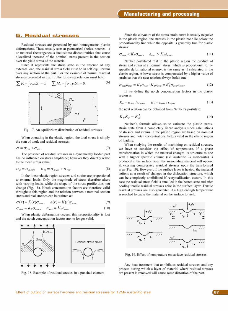
Since it represents the stress state in the absence of any external load, the residual stress field must be in self equilibrium over any section of the part. For the example of normal residual stresses presented in Fig. 17, the following relations must hold:
0,x xx xF dA
0.z xx xM ydA
(6)
Fig. 17. An equilibrium distribution of residual stresses
When operating in the elastic region, the total stress is simply the sum of work and residual stresses:
.res ext (7)
The presence of residual stresses in a dynamically loaded part has no influence on stress amplitude; however they directly relate to the mean stress value:
, ,a a ext , .m m ext res (8)
In the linear elastic region stresses and strains are proportional to external loads. Only the magnitude of stress therefore alters with varying loads, while the shape of the stress profile does not change (Fig. 18). Notch concentration factors are therefore valid throughout this region and the relation between a nominal section stress and real stresses can be written as:
( ) ( ) ,nomr K r ( ) ( ) ,nomr K r (9)
max ,E nomK max .E nomK (10)
When plastic deformation occurs, this proportionality is lost and the notch concentration factors are no longer valid.
Fig. 18. Example of residual stresses in a punched element
Since the curvature of the stress-strain curve is usually negative in the plastic region, the stresses in the plastic zone lie below the proportionality line while the opposite is generally true for plastic strains:
max ,E nomK max .E nomK (11)
Neuber postulated that in the plastic region the product of stress and strain at a nominal stress, which is proportional to the specific deformational energy, is the same as if calculated in the elastic region. A lower stress is compensated by a higher value of strain so that the next relation always holds true:
2max max .E nom E nom E nom nomK K K (12)
If we define the notch concentration factors in the plastic region as:
max / ,nomK max / ,nomK (13)
the next relation can be obtained from Neuber´s postulate:
2 .EK K K (14)
Neuber´s formula allows us to estimate the plastic stress-strain state from a completely linear analysis since calculations of stresses and strains in the plastic region are based on nominal stresses and notch concentrations factors valid in the elastic region of loading.
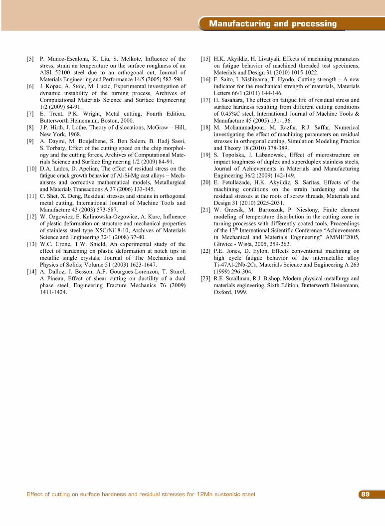
When studying the results of machining on residual stresses, we have to consider the effect of temperature. If a phase transformation in which the material changes its structure to one with a higher specific volume (i.e. austenite martensite) is produced in the surface layer, the surrounding material will oppose it, exerting compressive residual stresses upon the transformed area (Fig. 19). However, if the surface layer is heated, the material softens as a result of changes in the dislocation structure, which can be completely annihilated if recrystallization occurs. In this case the residual stress field is annulled in the heated state and after cooling tensile residual stresses arise in the surface layer. Tensile residual stresses are also generated if a high enough temperature is reached to cause the material on the surface to yield.
Fig. 19. Effect of temperature on surface residual stresses
Any heat treatment that annihilates residual stresses and any process during which a layer of material where residual stresses are present is removed will cause some distortion of the part.
87
Manufacturing and processing
Effect of cutting on surface hardness and residual stresses for 12Mn austenitic steel
Fig. 12. Results at constant cutting speed in direction 1
Fig. 13. Results at a constant feed rate in direction 1
It can be observed that the highest values are measured in the region immediately above the cutting edge and that afterwards the hardness of the material in the newly formed chip slightly decreases until it reaches a steady value at around 800µm from the selected origin. Interestingly, the shape of the hardness profile is almost the same for all chosen feed rates. It is clear from the presented results that an increase in feed has the effect of lowering the hardness of the material on the contact face of the chip. Subse-quently, the effect of cutting speed was researched at the feed rate that resulted in the smallest hardening (0.315 mm).
As can be seen from Fig. 13, increasing the cutting speed decreases hardening and additionally changes the shape of the hardness profile, specifically a steady value of hardness seems to be reached earlier at lower cutting speeds.
Measurements in direction 2 show substantially different hardness profiles than those presented above. As anticipated, the hardness of the machined surface is very high and comparable to that of the material in the chip. When moving away from the surface towards the bulk of the material, values of hardness decrease very rapidly and after a depth of approximately 0.6mm, which is intriguingly almost equal for all three cutting conditions, there are no signs of material hardening as micro-hardness values fall to those of non deformed austenite. In this case increasing the feed rate causes an increment of the level
of hardening as can be seen from Fig. 14. It is interesting to observe that the same action results in a hardness decrease in the chip (Fig. 12).
Increasing the cutting speed at constant feed has the same effect (Fig. 15), which is again antipodal to the effect on hardening in the cut-off material.
Fig. 14. Results at constant cutting speed in direction 2
Fig. 15. Results at a constant feed rate in direction 2
Fig. 16. Shear zone (cutting of specimen A4)
Fig. 16 shows a magnified view of the cutting zone for specimen A4. An arrangement of parallel lines directly in front of the shear plane is visible from both photographs which could be related to dislocation motion (slip planes, dislocation pile-ups…). This would confirm that some plastic deformation is present in the material before it passes through the shear plane.
5. Residual stresses
Residual stresses are generated by non-homogeneous plastic deformations. These usually start at geometrical (holes, notches…) or material (heterogeneous inclusions) discontinuities that cause a localized increase of the nominal stress present in the section over the yield stress of the material.
Since it represents the stress state in the absence of any external load, the residual stress field must be in self equilibrium over any section of the part. For the example of normal residual stresses presented in Fig. 17, the following relations must hold:
0,x xx xF dA
0.z xx xM ydA
(6)
Fig. 17. An equilibrium distribution of residual stresses
When operating in the elastic region, the total stress is simply the sum of work and residual stresses:
.res ext (7)
The presence of residual stresses in a dynamically loaded part has no influence on stress amplitude; however they directly relate to the mean stress value:
, ,a a ext , .m m ext res (8)
In the linear elastic region stresses and strains are proportional to external loads. Only the magnitude of stress therefore alters with varying loads, while the shape of the stress profile does not change (Fig. 18). Notch concentration factors are therefore valid throughout this region and the relation between a nominal section stress and real stresses can be written as:
( ) ( ) ,nomr K r ( ) ( ) ,nomr K r (9)
max ,E nomK max .E nomK (10)
When plastic deformation occurs, this proportionality is lost and the notch concentration factors are no longer valid.
Fig. 18. Example of residual stresses in a punched element
Since the curvature of the stress-strain curve is usually negative in the plastic region, the stresses in the plastic zone lie below the proportionality line while the opposite is generally true for plastic strains:
max ,E nomK max .E nomK (11)
Neuber postulated that in the plastic region the product of stress and strain at a nominal stress, which is proportional to the specific deformational energy, is the same as if calculated in the elastic region. A lower stress is compensated by a higher value of strain so that the next relation always holds true:
2max max .E nom E nom E nom nomK K K (12)
If we define the notch concentration factors in the plastic region as:
max / ,nomK max / ,nomK (13)
the next relation can be obtained from Neuber´s postulate:
2 .EK K K (14)
Neuber´s formula allows us to estimate the plastic stress-strain state from a completely linear analysis since calculations of stresses and strains in the plastic region are based on nominal stresses and notch concentrations factors valid in the elastic region of loading.
When studying the results of machining on residual stresses, we have to consider the effect of temperature. If a phase transformation in which the material changes its structure to one with a higher specific volume (i.e. austenite martensite) is produced in the surface layer, the surrounding material will oppose it, exerting compressive residual stresses upon the transformed area (Fig. 19). However, if the surface layer is heated, the material softens as a result of changes in the dislocation structure, which can be completely annihilated if recrystallization occurs. In this case the residual stress field is annulled in the heated state and after cooling tensile residual stresses arise in the surface layer. Tensile residual stresses are also generated if a high enough temperature is reached to cause the material on the surface to yield.
Fig. 19. Effect of temperature on surface residual stresses
Any heat treatment that annihilates residual stresses and any process during which a layer of material where residual stresses are present is removed will cause some distortion of the part.
5. residual stresses

Research paper88
Journal of Achievements in Materials and Manufacturing Engineering
M. Cebron, F. Kosel, J. Kopac
Volume 55 Issue 1 November 2012
5.1. Results of residual stress measurements
Residual stresses in the surface layer of the part were measured using an X-ray diffractometer. Results for the completely austenitic specimen A4 at two different cutting speeds and feed rates are presented in Fig. 20 and Fig. 21.
Fig. 20. Residual stresses at v=20 m/min
Increasing the feed rate in both cases brings about an increase in residual stresses. As expected, the higher values were measured directly on the surface, whereas afterwards stress levels decrease very rapidly with depth and after app. 0.25 mm the measured values of residual stresses are already negligible.
Fig. 21. Residual stresses at v=60 m/min
Increasing the cutting speed has the same effect which is nev-ertheless inferior to that of feed rate. The highest measured value was about 1300 N/mm2 and far exceeds the estimated ultimate tensile strength of the observed material (700-800 N/mm2). Despite this fact, no damage was found during the inspection of the surface. However, at cutting speeds exceeding 120 m/min visible surface cracks were generated.
While at all cutting parameters tensile residual stresses were found, slow grinding of specimen A4 induced compressive residual stresses in the surface with a maximum value of app. 200 N/mm2.
6. Conclusions Surface conditions resulting from the production process have
a strong effect on the performance of finished products, therefore any information linking the machining process to the mechanical state of the surface is valuable. In this study material hardening and residual stress induced during machining were examined for highly-hardening 12Mn austenitic steel.
A short outline of the mechanics of hardening in crystal materials is given, with specific properties presented for the face cantered cubic structure of austenite. The state of the cutting zone was researched using a quick-stop device capable of suddenly stopping the cutting process and so retaining the mechanical conditions developed during machining.
It was confirmed that the analysed material hardens substan-tially during machining and that the wear of cutting tools can be related both to this phenomenon and to the material structure after heat treatment. It is found that an increase of feed rate lowers the hardness of the material on the contact face of the chip and that increasing the cutting speed has the same effect while additionally changing the shape of the hardness profile. The hardness of the machined surface is comparable to that of the material in the chip, however when moving away from the surface, the values of hardness decrease very rapidly. In this case increasing the feed rate or the cutting speed causes an increment in the level of hardening. Both increasing the feed rate or the cutting speed have the effect of increasing residual stresses. At cutting speeds exceeding 120 m/min visible surface cracks were generated caused by extremely high tensile stresses which can be attributed to the combined effect of yielding and high temperatures.
Acknowledgements Operation part financed by the European Union, European
Social Fund. Operation implemented in the framework of the Operational Programme for Human Resources Development for the Period 2007-2013, Priority axis 1: Promoting entrepreneurship and adaptability, Main type of activity 1.1.: Experts and researchers for competitive enterprises.
References [1] J. Kopac, Hardening phenomena of austenite steels in the
cutting process, doctoral dissertation (in Slovenian), Faculty of mechanical engineering, University of Ljubljana, Ljubljana, 1986.
[2] R. Phillips, Crystals, defects and microstructures, Cambridge University Press, Cambridge, 2001.
[3] J. Grum, Surface integrity: microstructure and residual stresses, Faculty of Mechanical Engineering, University of Ljubljana, Ljubljana, 2009.
[4] M.H. El-Axir, A method of modeling residual stress distribution in turning for different materials, International Journal of Machine Tools & Manufacture 42 (2002) 1055-1063.
5.1. results of residual stress measurements
6. conclusions
Acknowledgements
references
[5] P. Munoz-Escalona, K. Liu, S. Melkote, Influence of the stress, strain an temperature on the surface roughness of an AISI 52100 steel due to an orthogonal cut, Journal of Materials Engineering and Performance 14/5 (2005) 582-590.
[6] J. Kopac, A. Stoic, M. Lucic, Experimental investigation of dynamic instability of the turning process, Archives of Computational Materials Science and Surface Engineering 1/2 (2009) 84-91.
[7] E. Trent, P.K. Wright, Metal cutting, Fourth Edition, Butterworth Heinemann, Boston, 2000.
[8] J.P. Hirth, J. Lothe, Theory of dislocations, McGraw – Hill, New York, 1968.
[9] A. Daymi, M. Boujelbene, S. Ben Salem, B. Hadj Sassi, S. Torbaty, Effect of the cutting speed on the chip morphol-ogy and the cutting forces, Archives of Computational Mate-rials Science and Surface Engineering 1/2 (2009) 84-91.
[10] D.A. Lados, D. Apelian, The effect of residual stress on the fatigue crack growth behavior of Al-Si-Mg cast alloys – Mech-anisms and corrective mathematical models, Metallurgical and Materials Transactions A 37 (2006) 133-145.
[11] C. Shet, X. Deng, Residual stresses and strains in orthogonal metal cutting, International Journal of Machine Tools and Manufacture 43 (2003) 573-587.
[12] W. Ozgowicz, E. Kalinowska-Ozgowicz, A. Kurc, Influence of plastic deformation on structure and mechanical properties of stainless steel type X5CrNi18-10, Archives of Materials Science and Engineering 32/1 (2008) 37-40.
[13] W.C. Crone, T.W. Shield, An experimental study of the effect of hardening on plastic deformation at notch tips in metallic single crystals; Journal of The Mechanics and Physics of Solids; Volume 51 (2003) 1623-1647.
[14] A. Dalloz, J. Besson, A.F. Gourgues-Lorenzon, T. Sturel, A. Pineau, Effect of shear cutting on ductility of a dual phase steel, Engineering Fracture Mechanics 76 (2009) 1411-1424.
[15] H.K. Akyildiz, H. Livatyali, Effects of machining parameters on fatigue behavior of machined threaded test specimens, Materials and Design 31 (2010) 1015-1022.
[16] F. Saito, I. Nishiyama, T. Hyodo, Cutting strength – A new indicator for the mechanical strength of materials, Materials Letters 66/1 (2011) 144-146.
[17] H. Sasahara, The effect on fatigue life of residual stress and surface hardness resulting from different cutting conditions of 0.45%C steel, International Journal of Machine Tools & Manufacture 45 (2005) 131-136.
[18] M. Mohammadpour, M. Razfar, R.J. Saffar, Numerical investigating the effect of machining parameters on residual stresses in orthogonal cutting, Simulation Modeling Practice and Theory 18 (2010) 378-389.
[19] S. Topolska, J. Labanowski, Effect of microstructure on impact toughness of duplex and superduplex stainless steels, Journal of Achievements in Materials and Manufacturing Engineering 36/2 (2009) 142-149.
[20] E. Fetullazade, H.K. Akyildiz, S. Saritas, Effects of the machining conditions on the strain hardening and the residual stresses at the roots of screw threads, Materials and Design 31 (2010) 2025-2031.
[21] W. Grzesik, M. Bartoszuk, P. Nies ony, Finite element modeling of temperature distribution in the cutting zone in turning processes with differently coated tools, Proceedings of the 13th International Scientific Conference “Achievements in Mechanical and Materials Engineering” AMME’2005, Gliwice - Wis a, 2005, 259-262.
[22] P.E. Jones, D. Eylon, Effects conventional machining on high cycle fatigue behavior of the intermetallic alloy Ti-47Al-2Nb-2Cr, Materials Science and Engineering A 263 (1999) 296-304.
[23] R.E. Smallman, R.J. Bishop, Modern physical metallurgy and materials engineering, Sixth Edition, Butterworth Heinemann, Oxford, 1999.
89
Manufacturing and processing
Effect of cutting on surface hardness and residual stresses for 12Mn austenitic steel
5.1. Results of residual stress measurements
Residual stresses in the surface layer of the part were measured using an X-ray diffractometer. Results for the completely austenitic specimen A4 at two different cutting speeds and feed rates are presented in Fig. 20 and Fig. 21.
Fig. 20. Residual stresses at v=20 m/min
Increasing the feed rate in both cases brings about an increase in residual stresses. As expected, the higher values were measured directly on the surface, whereas afterwards stress levels decrease very rapidly with depth and after app. 0.25 mm the measured values of residual stresses are already negligible.
Fig. 21. Residual stresses at v=60 m/min
Increasing the cutting speed has the same effect which is nev-ertheless inferior to that of feed rate. The highest measured value was about 1300 N/mm2 and far exceeds the estimated ultimate tensile strength of the observed material (700-800 N/mm2). Despite this fact, no damage was found during the inspection of the surface. However, at cutting speeds exceeding 120 m/min visible surface cracks were generated.
While at all cutting parameters tensile residual stresses were found, slow grinding of specimen A4 induced compressive residual stresses in the surface with a maximum value of app. 200 N/mm2.
6. Conclusions Surface conditions resulting from the production process have
a strong effect on the performance of finished products, therefore any information linking the machining process to the mechanical state of the surface is valuable. In this study material hardening and residual stress induced during machining were examined for highly-hardening 12Mn austenitic steel.
A short outline of the mechanics of hardening in crystal materials is given, with specific properties presented for the face cantered cubic structure of austenite. The state of the cutting zone was researched using a quick-stop device capable of suddenly stopping the cutting process and so retaining the mechanical conditions developed during machining.
It was confirmed that the analysed material hardens substan-tially during machining and that the wear of cutting tools can be related both to this phenomenon and to the material structure after heat treatment. It is found that an increase of feed rate lowers the hardness of the material on the contact face of the chip and that increasing the cutting speed has the same effect while additionally changing the shape of the hardness profile. The hardness of the machined surface is comparable to that of the material in the chip, however when moving away from the surface, the values of hardness decrease very rapidly. In this case increasing the feed rate or the cutting speed causes an increment in the level of hardening. Both increasing the feed rate or the cutting speed have the effect of increasing residual stresses. At cutting speeds exceeding 120 m/min visible surface cracks were generated caused by extremely high tensile stresses which can be attributed to the combined effect of yielding and high temperatures.
Acknowledgements Operation part financed by the European Union, European
Social Fund. Operation implemented in the framework of the Operational Programme for Human Resources Development for the Period 2007-2013, Priority axis 1: Promoting entrepreneurship and adaptability, Main type of activity 1.1.: Experts and researchers for competitive enterprises.
References [1] J. Kopac, Hardening phenomena of austenite steels in the
cutting process, doctoral dissertation (in Slovenian), Faculty of mechanical engineering, University of Ljubljana, Ljubljana, 1986.
[2] R. Phillips, Crystals, defects and microstructures, Cambridge University Press, Cambridge, 2001.
[3] J. Grum, Surface integrity: microstructure and residual stresses, Faculty of Mechanical Engineering, University of Ljubljana, Ljubljana, 2009.
[4] M.H. El-Axir, A method of modeling residual stress distribution in turning for different materials, International Journal of Machine Tools & Manufacture 42 (2002) 1055-1063.
[5] P. Munoz-Escalona, K. Liu, S. Melkote, Influence of the stress, strain an temperature on the surface roughness of an AISI 52100 steel due to an orthogonal cut, Journal of Materials Engineering and Performance 14/5 (2005) 582-590.
[6] J. Kopac, A. Stoic, M. Lucic, Experimental investigation of dynamic instability of the turning process, Archives of Computational Materials Science and Surface Engineering 1/2 (2009) 84-91.
[7] E. Trent, P.K. Wright, Metal cutting, Fourth Edition, Butterworth Heinemann, Boston, 2000.
[8] J.P. Hirth, J. Lothe, Theory of dislocations, McGraw – Hill, New York, 1968.
[9] A. Daymi, M. Boujelbene, S. Ben Salem, B. Hadj Sassi, S. Torbaty, Effect of the cutting speed on the chip morphol-ogy and the cutting forces, Archives of Computational Mate-rials Science and Surface Engineering 1/2 (2009) 84-91.
[10] D.A. Lados, D. Apelian, The effect of residual stress on the fatigue crack growth behavior of Al-Si-Mg cast alloys – Mech-anisms and corrective mathematical models, Metallurgical and Materials Transactions A 37 (2006) 133-145.
[11] C. Shet, X. Deng, Residual stresses and strains in orthogonal metal cutting, International Journal of Machine Tools and Manufacture 43 (2003) 573-587.
[12] W. Ozgowicz, E. Kalinowska-Ozgowicz, A. Kurc, Influence of plastic deformation on structure and mechanical properties of stainless steel type X5CrNi18-10, Archives of Materials Science and Engineering 32/1 (2008) 37-40.
[13] W.C. Crone, T.W. Shield, An experimental study of the effect of hardening on plastic deformation at notch tips in metallic single crystals; Journal of The Mechanics and Physics of Solids; Volume 51 (2003) 1623-1647.
[14] A. Dalloz, J. Besson, A.F. Gourgues-Lorenzon, T. Sturel, A. Pineau, Effect of shear cutting on ductility of a dual phase steel, Engineering Fracture Mechanics 76 (2009) 1411-1424.
[15] H.K. Akyildiz, H. Livatyali, Effects of machining parameters on fatigue behavior of machined threaded test specimens, Materials and Design 31 (2010) 1015-1022.
[16] F. Saito, I. Nishiyama, T. Hyodo, Cutting strength – A new indicator for the mechanical strength of materials, Materials Letters 66/1 (2011) 144-146.
[17] H. Sasahara, The effect on fatigue life of residual stress and surface hardness resulting from different cutting conditions of 0.45%C steel, International Journal of Machine Tools & Manufacture 45 (2005) 131-136.
[18] M. Mohammadpour, M. Razfar, R.J. Saffar, Numerical investigating the effect of machining parameters on residual stresses in orthogonal cutting, Simulation Modeling Practice and Theory 18 (2010) 378-389.
[19] S. Topolska, J. Labanowski, Effect of microstructure on impact toughness of duplex and superduplex stainless steels, Journal of Achievements in Materials and Manufacturing Engineering 36/2 (2009) 142-149.
[20] E. Fetullazade, H.K. Akyildiz, S. Saritas, Effects of the machining conditions on the strain hardening and the residual stresses at the roots of screw threads, Materials and Design 31 (2010) 2025-2031.
[21] W. Grzesik, M. Bartoszuk, P. Nies ony, Finite element modeling of temperature distribution in the cutting zone in turning processes with differently coated tools, Proceedings of the 13th International Scientific Conference “Achievements in Mechanical and Materials Engineering” AMME’2005, Gliwice - Wis a, 2005, 259-262.
[22] P.E. Jones, D. Eylon, Effects conventional machining on high cycle fatigue behavior of the intermetallic alloy Ti-47Al-2Nb-2Cr, Materials Science and Engineering A 263 (1999) 296-304.
[23] R.E. Smallman, R.J. Bishop, Modern physical metallurgy and materials engineering, Sixth Edition, Butterworth Heinemann, Oxford, 1999.