Effect of blade type on a 3D FC centrifugal fan · Effect of blade type on a 3D FC centrifugal fan...
13
Journal of the Serbian Society for Computational Mechanics / Vol. 8 / No. 1, 2014 / pp. 23-35 (UDC: 532.517) Effect of blade type on a 3D FC centrifugal fan A. Amjadimanesh 1 *, H. Ajam 2 and A. Hossein Nezhad 1 1 Department of Mechanical Engineering, University of Sistan and Baluchestan, Zahedan, Iran [email protected] *Corresponding author [email protected] 2 Mechanical Engineering Department, Ferdowsi University of Mashhad, Mashhad, Iran [email protected] Abstract In this paper, a 3D forward curved (FC) centrifugal fan is simulated numerically to predict the turbulent flow and pressure field of the fan. Through this numerical simulation, the various turbulent models are compared and the influence of blade shapes on the fan performance is examined. For this means, four turbulence models (k-ε, k-ω, RSM, Spallart Allmaras) are applied to choose the most suitable one. Also for three kinds of blade shapes (flat blade, circular blade and NACA4412 airfoil blade), the flow fields are simulated separately to determine the most efficient blade shape. In numerical analysis, FVM (finite volume method) is used to solve the governing equations. Steady state conditions and multiple reference frames, including a MRF (moving reference frame) for the rotor region and a stationary reference frame for stator region, are used for numerical modeling. The numerical results are validated with experimental data. It is observed that k- ε is the most suitable turbulence model and the circular blade is the most efficient shape for this type of fan. Keywords: Blade type, turbulence models, centrifugal fan, performance curve, CFD. 1. Introduction Because of wide industrial applications of centrifugal fans, the efficiency of these fans might have great influence on the energy consumption. Since the blades are one of the most important parts which convert kinetic energy to pressure in the fans, refining types of blades may improve the performance of fans. Experimental analysis is expensive and time consuming due to constructing and testing physical prototypes in a trial-and-error process, thus reducing the profit margins of the manufacturers. For this reason, CFD analysis with suitable turbulence modeling currently has more benefits than experimental works. Numerical simulations can provide quite accurate information on the fluid and flow behavior in the machine, and thus help the engineers obtain a thorough performance evaluation of a particular design. Some of the recent investigations in this field are as follows. Jafarzade, Hajari and Alishahi in 2007 [Jafarzadeh et al 2011] simulated a high-speed centrifugal pump. They compared numerical results with available experimental data. The effect of blade number on the efficiency was considered by three different (5, 6 and 7) blade numbers.
Transcript of Effect of blade type on a 3D FC centrifugal fan · Effect of blade type on a 3D FC centrifugal fan...

Journal of the Serbian Society for Computational Mechanics / Vol. 8 / No. 1, 2014 / pp. 23-35
(UDC: 532.517)
Effect of blade type on a 3D FC centrifugal fan
A. Amjadimanesh1*, H. Ajam
2 and A. Hossein Nezhad
1
1Department of Mechanical Engineering, University of Sistan and Baluchestan, Zahedan, Iran
*Corresponding author [email protected] 2Mechanical Engineering Department, Ferdowsi University of Mashhad, Mashhad, Iran
Abstract
In this paper, a 3D forward curved (FC) centrifugal fan is simulated numerically to predict the
turbulent flow and pressure field of the fan. Through this numerical simulation, the various
turbulent models are compared and the influence of blade shapes on the fan performance is
examined. For this means, four turbulence models (k-ε, k-ω, RSM, Spallart Allmaras) are applied
to choose the most suitable one. Also for three kinds of blade shapes (flat blade, circular blade
and NACA4412 airfoil blade), the flow fields are simulated separately to determine the most
efficient blade shape. In numerical analysis, FVM (finite volume method) is used to solve the
governing equations. Steady state conditions and multiple reference frames, including a MRF
(moving reference frame) for the rotor region and a stationary reference frame for stator region,
are used for numerical modeling. The numerical results are validated with experimental data. It is
observed that k- ε is the most suitable turbulence model and the circular blade is the most
efficient shape for this type of fan.
Keywords: Blade type, turbulence models, centrifugal fan, performance curve, CFD.
1. Introduction
Because of wide industrial applications of centrifugal fans, the efficiency of these fans might
have great influence on the energy consumption. Since the blades are one of the most important
parts which convert kinetic energy to pressure in the fans, refining types of blades may improve
the performance of fans.
Experimental analysis is expensive and time consuming due to constructing and testing
physical prototypes in a trial-and-error process, thus reducing the profit margins of the
manufacturers. For this reason, CFD analysis with suitable turbulence modeling currently has
more benefits than experimental works. Numerical simulations can provide quite accurate
information on the fluid and flow behavior in the machine, and thus help the engineers obtain a thorough performance evaluation of a particular design. Some of the recent investigations in this
field are as follows.
Jafarzade, Hajari and Alishahi in 2007 [Jafarzadeh et al 2011] simulated a high-speed
centrifugal pump. They compared numerical results with available experimental data. The effect
of blade number on the efficiency was considered by three different (5, 6 and 7) blade numbers.

А. Amjadimanesh et al.: Effect of blade type on a 3D FC centrifugal fan
24
Three turbulence models (standard k-ε, RNG k- ε and RSM) were applied to choose the suitable
model. They introduced RNG k- ε and 7 blades as the most suitable and efficient model and
blade number. Lin and Huang in 2001 [Lin et al 2002] investigated a forward curved centrifugal
fan with airfoil NACA4412 blades by STAR-CD CFD code and validated their numerical results
with experimental data. They considered three blade inlet angles to find the most efficient one.
Their results indicated that 16.5° blade inlet angle resulted in the highest efficiency for the fan.
Tsai and Wu in 2006 [Tsai et al 2007] modeled a small centrifugal fan and compared numerical
and experimental results. They simulated three-dimensional turbulent flow of the fan at steady
state situation. They also observed that increasing the rotational speed of the rotor leads to the higher mass flow rate and static pressure. Younsi and Bakir in 2007 [Younsi et al 2007] studied
(numerically and experimentally) the influence of the impeller geometry on the unsteady flow in
a centrifugal fan. Three types of impeller (irregular blade spacing, different blade number,
smaller inlet diameter of the impeller) were compared with a reference impeller to evaluate the
influence of impeller geometry on performance of the fan. Wang and Zhang in 2009 [Wang et al
2009] numerically simulated a G4-27 centrifugal fan (a backward airfoil blade centrifugal fan).
They chose efficiency as an objective function and did an optimization analysis by the least
square method assuming the blade number and blade angle as the goal functions. Their
optimization results showed that the performance of centrifugal fan is improved by reducing the
energy loss which induced by the secondary flow vortex, the volute tongue, the wake-jet and the
angle of attack. Optimization results predicted that the maximum efficiency (76.85%) occurs in
14 blade number and 44.5° blade angle. Singh and coworkers in 2011 [Singh et al 2011] investigated effects of backward centrifugal fan parameters (such as blade number, outlet blade
angle and diameter ratio) on performance thorough experiments and CFD simulations. They used
the concept of MRF (moving reference frame) to obtain flow field in the rotating region. They
simulated two backward centrifugal fans with different blade numbers and compared the results
with experiments to validate their model. In order to study effects of blade number on the
performance of the fan, they simulated four other blade numbers for this backward centrifugal
fan. They reported that increase in the number of blade increases the flow coefficient and
efficiency. Lee and coworkers in 2011 [Lee et al 2011] presented numerical CFD optimization
with experiential steering technique to redesign the backward centrifugal fan profile, inlet duct
and shroud of the impeller. The goal of optimization was to reduce power consumption while
maintaining a specified output pressure at the lift-side volute exit. The design modification was completed by decoupling the impeller from volute. The 2D blade profile optimization based on
numerical coupling between a CFD calculation and a genetic algorithm optimization scheme was
able to achieve a composite objective with a projected shaft power and a power output.
Pranav and Raj in 2012 [Pranav et al 2012] numerically designed and parametrically
optimized the volute casing of a backward airfoil blade (NACA2424) centrifugal fan. They
presented the design methodology. The concept of MRF was used in the CFD analysis for
rotating region around the impeller. The volute casing was optimized by decreasing the volute
clearance and increasing the cut off height and keeping it at 35% of impeller diameter.
According to Eck [Eck et al 1973] the type of blades in fan cannot be determined
theoretically. However, it is time consuming and costly to determine type of blades
experimentally as it requires large number of prototypes of fan to be made. CFD has become an important tool to investigate such kind of problems.
The above review shows that most of previous works focused on the blade number of
backward fans and a few of the previous works includes the study of 3D modeling within a full
domain considering interaction between rotor and stator of a forward curved centrifugal fan
using various turbulence models and different blade types.
So in this paper, the effects of various turbulence models and different blade types on the
flow field and efficiency of a 3D forward curved centrifugal fan are studied. Commercial CFD

Journal of the Serbian Society for Computational Mechanics / Vol. 8 / No. 1, 2014
25
code is used for this numerical simulation. Run time and precision of various model, and the
effect of blade type on the characteristics of the fan are investigated.
2. Numerical scheme and governing equations
The flow in the fan is turbulent and is assumed to be steady and incompressible (in this air
condition, the Mach number of the flow is much lower than 0.3 [Dixon et al 2010]). Governing
equations include conservation of mass and momentum equations (Eq.1, 2, 3) and two transport
equations for turbulence kinetic energy and turbulence dissipation, k-ε model (Eq.4, 5). For rotor
region, rotating reference frame and for stator region, stationary reference frame are used. No
slip boundary condition is utilized on the walls. The atmospheric conditions are set as the boundary conditions at both the inlet and outlet of fan.
The equations of Conservation; mass, momentum, turbulent kinetic energy and turbulent
dissipation rate are as followed (respectively) [Versteeg et al 2007]:
0)v.(ρ
(1)
)τ.(p)vv.(ρ
(In the stator region) (2)
τP)rωωvωρ(2)vv.(ρ rrr
(In the rotor region) (3)
εGx
k)
σ
μ(μ
x(k)
tk
jk
t
j
(4)
k
εCG
k
εC
x
ε)
σ
μ(μ
x)(
t
2
2εk1ε
jε
t
j
(5)
where,
Iv.
3
2)vv(μτ T
ε
kρCμ
2
μt
2
tk SμG
)
x
u
x
u(
2
1S
S2SS
j
i
i
j
ij
ijij
ρ is the density, v
is velocity vector, p is the pressure, μ and μt are the dynamic viscosity and
turbulent dynamic viscosity respectively, τ is the shear stress tensor, rv
is the relative velocity
vector, ω
is the angular velocity vector, k is turbulent kinetic energy, ε is turbulent dissipation

А. Amjadimanesh et al.: Effect of blade type on a 3D FC centrifugal fan
26
rate, kG is the generation of turbulent kinetic energy due to mean velocity gradients, S is the
modulus of the mean rate-of-strain tensor, ijS is the mean strain rate, and turbulent constants are:
1.3σ1,σ0.09,C1.92,C1.44,C εkμ2ε1ε
Regarding to the complex geometry of fan SIMPLE algorithm is used to solve coupled velocity
and pressure field [Jafarzadeh et al 2011]. In addition, convective terms are discretized with the second-order upwind scheme. In the second-order approach, higher-order accuracy is achieved at
cell faces through a Taylor series expansion of the cell-centered solution about the cell center.
3. Fan specification
The fan investigated here is shown at figure 1. This fan is a forward curved centrifugal fan with
17 blade number and 16.5° inlet blade angle (according to Reference [Lin et al 2002] among
angles of 0°, 16.5°, 26.5° the angle (16.5°) is the most efficient one) which is used for cooling
the notebook computers. Its other geometric parameters are presented in table 1.
Fig. 1. Fan geometry [Lin et al 2002]
Fig. 2. Blade shapes

Journal of the Serbian Society for Computational Mechanics / Vol. 8 / No. 1, 2014
27
Blade number 17 Blade inlet radius 13 mm
Blade angle 16.5 Blade outlet radius 16.4 mm
Blade chord length 3.4 mm Inlet area π×16.5×16.5 mm2
Rotational speed 5000 rpm Outlet area 45×6.2 mm2
Blade height 4.2 mm Blade thickness 0.75 mm
Table 1. fan specification
The base blade shape is airfoil NACA4412. For evaluation, influence of blade shape on
performance of the fan, circular arc blade (60 degree) and flat blade are chosen for investigation
(figure 2). In all cases, chord line length and mean thickness of the blade are equal and constant.
Because of it is focused only on the blade shape, other parameters of the fan like blade number,
rotational speed and inlet angle are assumed constant in all the cases.
4. Grid generation
The grid system for the fan is shown in figure.3. Figure. 3(a) shows the overall scheme of grid
system. figure. 3(b) demonstrates grid system in top view and figure 3(c) represents mesh of
airfoil blades in rotor regions. Stator and rotor grid generation are performed separately and then
joined to each other. Hexahedral mesh is used in stator region to obtain better accuracy.
Regarding to the complex geometry of the rotor a high quality unstructured mesh is used for this
region. The quality of mesh generation is checked of aspect ratio and skewness. The aspect ratio
of 100 percent of grids are in the range of 1 and 5 and the skewness of about 90 percent of grids
are lower than 0.5 (High quality grid generation).
In order to capture the details of the flow field, around the walls and high velocity and
pressure gradient region the mesh number is increased. Note that the grid generations of arc and flat blade types are similar to airfoil blade mesh and more convenient. So for simplification, only
the airfoil blade mesh (the most complicated one) has been presented.
(a)

А. Amjadimanesh et al.: Effect of blade type on a 3D FC centrifugal fan
28
(b) (c)
Fig. 3. Grid system airfoil blade: (a) 3D mesh (b) mesh in horizontal plane (c) rotor region in
horizontal plane
5. Grid study
It must be shown that the numerical results are independent of grid size. For this means, mesh
number is increased by a factor of two, and variation of maximum volume flow rate of fan is
computed (results have obtained in atmospheric pressure outlet and airfoil blade type). Figure 4
shows the variation of static pressure of fan with volume flow rate (performance curve) for a set
of mesh numbers. As shown, the results between 504000 and 1050000 mesh number are close to
each other. (Results have obtained in atmospheric pressure outlet, 17 blade number and 5000
rpm).
Fig. 4. Grid study for fan performance
As shown in the Table. 2, variation of results by increasing the mesh number from 504000 to
1050000 is very small and the percent change is 0.11%. Therefore regarding to computational
cost, the 504000 mesh number is appropriate and sufficient (it is noted that grid study results for
0
5
10
15
20
25
30
0 0,0002 0,0004 0,0006 0,0008 0,001
sta
tic p
ressu
re (
Pa)
volume flow rate (m^3/s)
grid study for fan performance
127000
248000
504000
1050000

Journal of the Serbian Society for Computational Mechanics / Vol. 8 / No. 1, 2014
29
other shapes of blades are very similar to these results, so they have been eliminated to avoid
repetition).
Grid
number
Max. volume flow
rate(m^3/s) Percent change
127000 7.413×10⁴ -
248000 7.834×10⁴ 5.67
504000 7.934×10⁴ 1.27
1050000 7.943×10⁴ 0.11
Table 2 grid study
5. Validation
To validate numerical simulation, experimental data reported are compared with numerical
results of k-ε model. Since performance curve (static pressure versus volume flow rate), presents
general characteristic of centrifugal fans, this curve has been chosen to validate numerical results
with experimental data. According to figure 5, numerical and experimental results are in good
agreement and the maximum error percentage occurs about 15Pa static pressure, which is less than 4%.
Fig. 5. Validation of numerical results with experimental data
6. Results and discussion
Three shapes of blades are considered to study. The results are presented in the form of
performance curve (figure 6), power (figure 7) and efficiency of fan (figure 8). For this purpose
non-dimensional numbers such as power coefficient, flow coefficient and efficiency are defined
as follows [Bleier et al 1998]:
0
5
10
15
20
25
30
0 0,0002 0,0004 0,0006 0,0008 0,001
sta
tic p
ressure
(pa)
volume flow rate (m^3/s)
Performance Curve numerical results
experimental data
Poly. (numericalresults)

А. Amjadimanesh et al.: Effect of blade type on a 3D FC centrifugal fan
30
5353 DρN
ω.T
DρN
PP̂
(Power coefficient)(6)
3ND
QΦ (Flow coefficient)(7)
.T
PQ.η
(Efficiency)(8)
Where T
is torque of the shaft, ω
is rotational speed vector, ρ is air density, N is rotational
speed, D is diameter of impeller, Q is volume flow rate and P is the variation of pressure
throughout the fan.
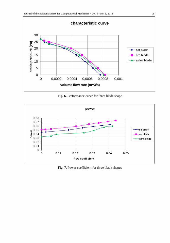
Figure 6 demonstrates that static pressure increases with reduction of volume flow rate, and the behavior of all blade types are similar. Moreover, it shows that arc blades are better in
guidance of fluid and so the flow rate of fan increases in this case. Figure 7 demonstrates that
energy consumption of fan also increases in arc blades (due to friction) and the power of fan is
greater than other blades shapes.
Total results may be presented in the form of efficiency graph. Figure 8 indicates that the
maximum efficiency occurs for arc blades in the flow coefficient of about 0.023. In other words,
positive effectiveness of flow guidance overcomes the negative influence of friction.
Velocity contours and stream line diagram of fan at the horizontal mid plane is presented for
the case of circular arc blade to show details of velocity flow field in figure 9, (Because of the
similarity of flow pattern for all types of blade, only the arc blade velocity contours are reported.)
figure 9(a) shows the velocity contours diagram of inlet region for circular arc blade type. The inlet fluid is sucked into the fan and turns with the rotating rotor, the entrance flow changes from
axial at the mouth of the inlet to radial at the back plate, and a significant recirculation pattern
exists near the inlet zone. Thereafter, the flow leaves this region to enter the rotor and to receive
the energy by means of contact with blade surfaces. Finally, all the flows are collected in the
housing and discharged from the outlet.
As shown in the figure 9(a) the velocity magnitudes in the front of blades are less than the
back of the blades (noting the fact that pressure values in the front of blade are more than the
back of blade). In addition, velocity magnitudes gradually increase from inside to outside. The
maximum speed is about 9m/s. Figure 9(b) demonstrates streamlines of flow in the horizontal
middle plane. As shown in figure 9(b) the recirculation occurs in the outlet of fan where the
direction of outlet plane and blades (that conduct the fluid) is not matched to each other. Figure
10 shows the velocity contour diagram of inlet region at section AA (see figure 1) for circular arc blade type. The incoming fluid is sucked into the fan and turns with the rotating rotor. Figure 10
also illustrates a similar flow pattern in the inlet region at section BB, which is perpendicular to
section AA
Journal of the Serbian Society for Computational Mechanics / Vol. 8 / No. 1, 2014
31
Fig. 6. Performance curve for three blade shape
Fig. 7. Power coefficient for three blade shapes
0
5
10
15
20
25
30
0 0,0002 0,0004 0,0006 0,0008 0,001
sta
tic p
ressu
re (
Pa)
volume flow rate (m^3/s)
characteristic curve
flat blade
arc blade
airfoil blade

А. Amjadimanesh et al.: Effect of blade type on a 3D FC centrifugal fan
32
Fig. 8. Efficiency for three blade shapes
(a) (b)
Fig. 9. Calculated velocity distribution of circular blades: (a) velocity magnitude contour (m/s)
(b) stream lines of flow field

Journal of the Serbian Society for Computational Mechanics / Vol. 8 / No. 1, 2014
33
Fig. 10. Calculated flow patterns on rotor and at section AA, BB (m/s)
7. Turbulence models
To study the influence of turbulence models on centrifugal fan simulation, four turbulence
models are considered. Spalart-Allmaras model (one transport equation based on kinetic energy),
k-ε model (two equations method based on kinetic energy and dissipation rate), k-ω (two
equations method based on kinetic energy and turbulence frequency) and RSM model (seven
transport equations based on Reynolds stresses) are compared to each other and the results
presented in Table.3. All results, which are reported in Table.3, are computed for airfoil blade
type centrifugal fan. Each case has been run on a Core 2 Duo 2.26 GHz (Cache 3MB) computer with 4096 MB Ram. (Error percentage is reported due to maximum flow rate in atmospheric
pressure outlet and is compared to experimental results of reference [Lin et al 2002].)
turbulence model convergence order grid number
computational time
(hour)
Max. flow rate
(m3/s) error percentage
Spalart-Allmaras 10-4
504000 4.6 7.729×10⁻⁴
7.1
k-ε 10-5
504000 6 8.037×10⁻⁴
3.4
k-ω 10-4
504000 6.2 7.870×10⁻⁴
5.4
RSM 10-3
504000 13 8.078×10⁻⁴
2.
Table 3. Turbulence models
Note that the uncertainty of experimental measurement is 2% [Lin et al 2002]. This uncertainty
may cause a concern about the error percentages which obtain from different turbulence models.
The quantity of maximum flow rate of experimental measurement has been reported as
8.320×10⁻⁴, which is greater than all maximum flow rates of various turbulence models. So the concern would not have an important effect on the accuracy ranking of different models.
As table.3 presents the lowest error percentage relevant to RSM model, which solves seven
equations of, Reynolds stresses. Regarding to large computational cost and second order of
convergency for this model, usage of this model has not economical advantage. After RSM
model, k-ε model has the lowest error percentage. According to high order of convergency and
appropriate computational cost, k-ε model can simulate the flow field of the fan accurately and
quickly.

А. Amjadimanesh et al.: Effect of blade type on a 3D FC centrifugal fan
34
8. Conclusion
In this paper, a forward curved centrifugal fan was numerically simulated and its performance
curve was compared with experimental data. Regarding to good agreement of these results, the
present numerical modeling of fan may predict the flow field of fan with details. Therefore,
expensive cost of experimental works can be avoided by using computational fluid dynamics.
Then, influence of blade shape on performance of the fan was studied and circular arc blades
type is introduced as the most efficient blade shape. Four turbulence models are considered in
case of accuracy and computational cost. The k-ε model is suggested for numerical simulation of
centrifugal fans. Regarding to similarities of flows in centrifugal fan and centrifugal pumps, these results may be useful for numerical simulation of centrifugal pumps.
Acknowledgments
Special thanks to HEDCo (Hampa Engineering and Design Company), Shiraz, Iran.
Извод
Утицај облика лопатица код 3D FC центрифугалних вентилатора
A. Amjadimanesh
1*, H. Ajam
2 and A. Hossein Nezhad
1
1Department of Mechanical Engineering, University of Sistan and Baluchestan, Zahedan, Iran
*Corresponding author [email protected] 2Mechanical Engineering Department, Ferdowsi University of Mashhad, Mashhad, Iran
[email protected]Резиме
У овом раду, врши се нумеричка симулација 3D предње закривљеног (FC) центрифугалног вентилатора ради могућности предвиђања турбулентних протока и притиска поље
вентилатора. Путем ове нумеричке симулације, пореде се разни модели и испитује се
утицај облика лопатица вентилатора на перформансе његовог рада. То би значило да се
врши примена четири модела турбуленције (к-ε, К-ω, RSM, Spallart Allmaras) како би се
изабрао најпогоднији. Такође за три врсте облика лопатица (равна, кружна и NACA4412
аеропрофил), поља протока врше засебну симулацију ради одређивање најефикаснијег
облика лопатица вентилатора. У нумеричке анализе, FVM (метода коначних запремина) се
користи за решавање једначине. Услови стабилности стања и више-референтних система,
укључујући и MRF (покретни референтни оквир) за област ротора и непокретног
референтног оквира за област статора, користе се за нумеричко моделирање. Нумерички
резултати су потврђени експерименталним подацима. Уочено је да је k- ε најпогоднији
модел турбуленције и да кружна лопатица има најефикаснији облик за ову врсту вентилатора.
Кључне речи: врста лопатице, модели турбуленције, центрифугални вентилатор,
перформанса криве, CFD.

Journal of the Serbian Society for Computational Mechanics / Vol. 8 / No. 1, 2014
35
References
Jafarzadeh B, Hajari A, Alishahi MM, Akbari MH: The flow simulation of a low-specific-speed
high-speed centrifugal pump. Applied Mathematical Modelling, 35(1):242-249,2011.
Lin S-C, Huang C-L: An integrated experimental and numerical study of forward–curved
centrifugal fan. Experimental Thermal and Fluid Science, 26(5):421-434,2002.
Tsai BJ, Wu CL: Investigation of a miniature centrifugal fan. Applied Thermal Engineering,
27(1):229-239, 2007.
Younsi M, Bakir F, Kouidri S, Rey R: Influence of Impeller Geometry on the Unsteady Flow in a
Centrifugal Fan: Numerical and Experimental Analysis. International Journal of Rotating Machinery 2007:10.1155/2007/34901, 2007.
Wang S, Zhang L, Wu Z, Qian H: Optimization Research of Centrifugal Fan with Different
Blade Number and Outlet Blade Angle. Power and Energy Engineering Conference,
APPEEC 2009, Asia-Pacific, 1:27-31, 2009.
Singh OP, Khilwani R, Sreenivasulu T, Kannan M: Parametric Study of Centrifugal Fan
Performance: Experiments and Numerical Simulation. International Journal of Advances in
Engineering & Technology, 1(2):33-50, 2011.
Lee Y-T, Ahuja V, Hosangadi A, Slipper ME, Mulvihill LP, Birkbeck R, Coleman R: Impeller
Design of a Centrifugal Fan with Blade Optimization. International Journal of Rotating
Machinery, 2011:16, 2011.
Pranav CA, Raj RTK: Numerical Design and Parametric Optimization of Centrifugal Fans with
Airfoil Blade Impellers. Research Journal of Recent Sciences, 1(10):7-11, 2012. Eck B: Fans; design and operation of centrifugal, axial-flow, and cross-flow fans: Pergamon
Press; 1973.
Dixon SL, Hall CA: Fluid mechanics and thermodynamic of turbomachinery: Elsevier, USA,
2010.
Versteeg HHK, Malalasekera W: An introduction to computational fluid dynamics: the finite
volume method: Pearson Education Australia; 2007.
Bleier F: Fan Handbook: Selection, Application, and Design: McGraw-Hill Education; 1998.