EEXPERIENCE & PASSIONXPERIENCE & PASSION · JUEGO DE LA MANETA FRENO DELANTERO La maneta del freno...
112
MANUAL DE PROPIETARIO / OWNER’S MANUAL / MANUEL DU PROPRIÉTAIRE MANUAL DE PROPIETARIO / OWNER’S MANUAL / MANUEL DU PROPRIÉTAIRE EXPERIENCE & PASSION EXPERIENCE & PASSION
Transcript of EEXPERIENCE & PASSIONXPERIENCE & PASSION · JUEGO DE LA MANETA FRENO DELANTERO La maneta del freno...
MANUAL DE PROPIETARIO / OWNER’S MANUAL / MANUEL DU PROPRIÉTAIREMANUAL DE PROPIETARIO / OWNER’S MANUAL / MANUEL DU PROPRIÉTAIREE X P E R I E N C E & PA S S I O NE X P E R I E N C E & PA S S I O N

2
3
¡ Enhorabuena por su elección !¡ Enhorabuena por su elección !
Queremos darle la bienvenida a Vertigo Motors y compartir con usted nuestra experiencia y pasión por el trial,Queremos darle la bienvenida a Vertigo Motors y compartir con usted nuestra experiencia y pasión por el trial,el diseño, la técnica, la innovación y la investigación.el diseño, la técnica, la innovación y la investigación.
Vertigo nace de la inquietud de evolucionar las motos de trial para llevarlas al siguiente nivel.
En Vertigo soñamos cual sería la moto ideal para la práctica de nuestra pasión, sin distinciones entre afi cionadoso profesionales, una moto revolucionaria pensada para usted.
Desde ahora usted entra a formar parte de nuestro equipo, integrándose con el mejor equipo técnico, pilotos, apasionados del motor y los mejores profesionales en cada especialidad. Todos con un denominador común: Pasión y ExperienciaPasión y Experiencia.
En Vertigo, además, queremos ofrecerle la posibilidad de practicar el trial en un área privada reservada (Noassar)(Noassar),ubicada en Camprodón dentro del complejo hotelero Hotel Puig-Francó y en el que podrá disfrutar de su pasión por el trial.
Para más información visite la web: www.puigfranco.eswww.puigfranco.es
Con este manual le proporcionamos los datos, tareas de mantenimiento y reglajes básicos que usted mismo podrá realizar en su nueva Vertigo. Asimismo, en su Concesionario Ofi cial Vertigo Motors encontrará el equipo de expertos que podrán
asesorarle sobre todos los temas relacionados con su motocicleta y sus complementos.
Le invitamos a formar parte de nuestra historia y de nuestro éxito.
Vertigo Motors se reserva el derecho a efectuar cambios y/o modifi caciones en sus modelos sin previo aviso.
ES
PA
ÑO
LE
SPA
ÑO
LE
NG
LIS
HE
NG
LIS
HFR
AN
ÇA
ISFR
AN
ÇA
IS

4
5
Presentación y agradecimientoPresentación y agradecimientoSimbología utilizada al manualSimbología utilizada al manualConsejos de seguridadConsejos de seguridadLarga inactividad de la motocicletaLarga inactividad de la motocicletaIdentifi cación de la motocicletaIdentifi cación de la motocicletaIdentifi cación elementos de la motocicletaIdentifi cación elementos de la motocicletaElementos básicos para arrancar la motocicletaElementos básicos para arrancar la motocicletaMantenimientoMantenimiento
ManillarManeta del freno delanteroManeta del embragueJuego de la maneta del freno delanteroJuego de la maneta del embragueLíquido de la maneta del freno delanteroLíquido de la maneta del embragueLíquido del freno trasero3 posiciones de embragueFiltro del aireBujíaMantenimiento de la rejilla del radiadorLíquido refrigerantePastillas del freno delanteroPastillas del freno traseroAmortiguación delanteraAmortiguadorCadenaNeumáticosAceite del motor
0306070809
10-1112-13
14151516161717181819
20-212122222324
25-26272828
293031
32-3334-37
ÍNDICEÍNDICE
LubricadoPares de aprietePares de aprieteHomologaciónHomologaciónTabla de mantenimientoTabla de mantenimientoDatos técnicosDatos técnicos
ES
PA
ÑO
LE
SPA
ÑO
LE
NG
LIS
HE
NG
LIS
HFR
AN
ÇA
ISFR
AN
ÇA
IS
6
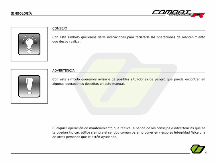
CONSEJO
Con este símbolo queremos darle indicaciones para facilitarle las operaciones de mantenimiento que desee realizar.
ADVERTENCIA
Con este símbolo queremos avisarle de posibles situaciones de peligro que pueda encontrar en algunas operaciones descritas en este manual.
Cualquier operación de mantenimiento que realice, a banda de los consejos o advertencias que se te puedan indicar, utilice siempre el sentido común para no poner en riesgo su integridad física o la de otras personas que le estén ayudando.
SIMBOLOGÍASIMBOLOGÍA
7
Antes de la utilización de esta moto familiarícese con ella, sitúe e identifi que todos los elementos básicos para la conducción.
Lea atentamente todos y cada uno de los apartados de este manual.
Esta moto ha sido fabricada para uso exclusivo del trial por lo que no podrá llevar a un segundo pasajero.
Realice las operaciones de mantenimiento descritas en este manual y en el momento que se indica para que su moto se man-tenga en buen estado el máximo de tiempo posible.
Use equipación adecuada para la practica del Trial que garantice su integridad (casco, ropa adecuada, protecciones, etc...).
Utilice la moto de forma progresiva hasta alcanzar su máximo rendimiento.
Evite arrancar la moto con el caballete puesto.
CONSEJOS DE SEGURIDADCONSEJOS DE SEGURIDAD
ES
PA
ÑO
LE
SPA
ÑO
LE
NG
LIS
HE
NG
LIS
HFR
AN
ÇA
ISFR
AN
ÇA
IS
8
Es necesario adoptar ciertas medidas para garantizar el buen mantenimiento de la moto en caso de larga inactividad del vehículo:
- Proceder a un limpieza completa de la moto antes de su almacenamiento.
- Reducir la presión de los neumáticos.
- Cubrir la moto con una funda para evitar el polvo y la suciedad.
LARGA INACTIVIDAD DE LA MOTOCICLETALARGA INACTIVIDAD DE LA MOTOCICLETA
9
IDENTIFICACIÓN DE LA MOTOIDENTIFICACIÓN DE LA MOTO
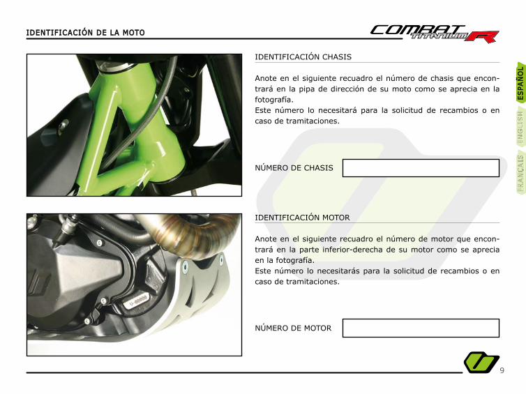
IDENTIFICACIÓN CHASIS
Anote en el siguiente recuadro el número de chasis que encon-trará en la pipa de dirección de su moto como se aprecia en la fotografía.Este número lo necesitará para la solicitud de recambios o en caso de tramitaciones.
NÚMERO DE CHASIS
NÚMERO DE MOTOR
IDENTIFICACIÓN MOTOR
Anote en el siguiente recuadro el número de motor que encon-trará en la parte inferior-derecha de su motor como se aprecia en la fotografía.Este número lo necesitarás para la solicitud de recambios o en caso de tramitaciones.
ES
PA
ÑO
LE
SPA
ÑO
LE
NG
LIS
HE
NG
LIS
HFR
AN
ÇA
ISFR
AN
ÇA
IS
10
IDENTIFICACIÓN ELEMENTOS DE LA MOTOIDENTIFICACIÓN ELEMENTOS DE LA MOTO
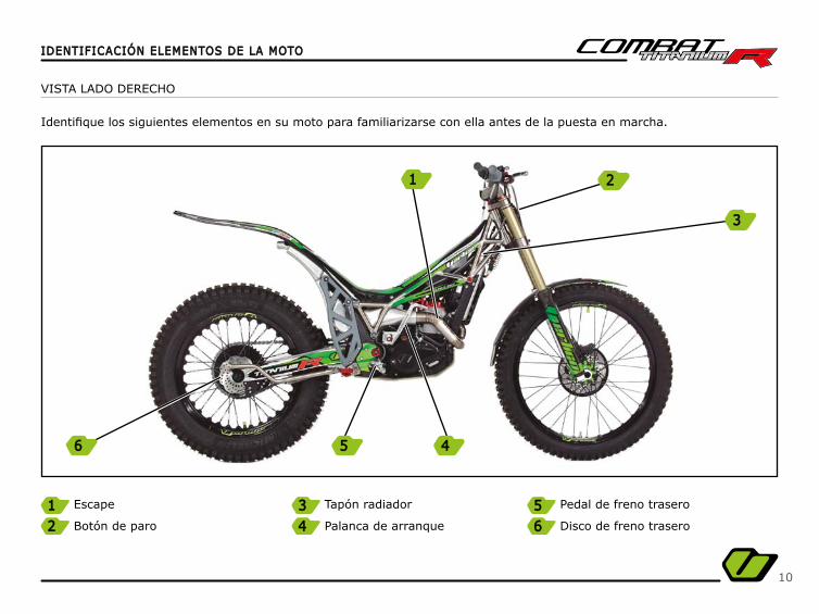
VISTA LADO DERECHO
Identifi que los siguientes elementos en su moto para familiarizarse con ella antes de la puesta en marcha.
Escape
Botón de paro
Tapón radiador
Palanca de arranque
Pedal de freno trasero
Disco de freno trasero
1 3 52 4 6
56 4
1
3
2

11
IDENTIFICACIÓN ELEMENTOS DE LA MOTOIDENTIFICACIÓN ELEMENTOS DE LA MOTO
Suspensión delantera
Silencioso
Plato de arrastre
Palanca del cambio
Disco de freno delantero
Llenado depósito de gasolina
VISTA LADO IZQUIERDO
Identifi que los siguientes elementos en su moto para familiarizarse con ella antes de la puesta en marcha.
7 9 11118 12121010
ES
PA
ÑO
LE
SPA
ÑO
LE
NG
LIS
HE
NG
LIS
HFR
AN
ÇA
ISFR
AN
ÇA
IS
7 1212
1111 1010 9
8

12
DEPÓSITO DE GASOLINA
El acceso al depósito de gasolina se encuentra en el centro de la moto.
Gire la anilla (A) hacia la izquierda y tire la tapa hacia atrás para acceder al tapón de llenado.
Utilice siempre gasolina 95oct o 98oct con una mezcla de aceite 2T de 0’75%.
Retire cualquier resto de gasolina que haya tenido contactocon componentes de la moto para evitar que sean dañadas.
ELEMENTOS BÁSICOS PARA LA ARRANCADA DE LA MOTOELEMENTOS BÁSICOS PARA LA ARRANCADA DE LA MOTO
A
13
ELEMENTOS BÁSICOS PARA LA ARRANCADA DE LA MOTOELEMENTOS BÁSICOS PARA LA ARRANCADA DE LA MOTO
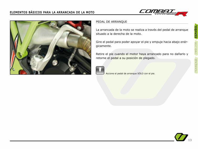
PEDAL DE ARRANQUE
La arrancada de la moto se realiza a través del pedal de arranque situado a la derecha de la moto.
Gire el pedal para poder apoyar el pie y empuje hacia abajo enér-gicamente.
Retire el pie cuando el motor haya arrancado para no dañarlo y retorne el pedal a su posición de plegado.
Accione el pedal de arranque SÓLO con el pie.
ES
PA
ÑO
LE
SPA
ÑO
LE
NG
LIS
HE
NG
LIS
HFR
AN
ÇA
ISFR
AN
ÇA
IS

14
MANTENIMIENTOMANTENIMIENTO
Ajuste la distancia del manillar.distancia del manillar.
Dispone de 4 posiciones diferentes para adaptar el manillar a su gusto.
Invirtiendo la posición de las bridas de manillar puede acercar o alejar el manillar.
Modifi cando el anclaje de la brida de manillar a la platina con las dos posiciones disponibles, puede alejar o acercar el manillar.
MANILLAR
Ajuste la inclinación del manillarinclinación del manillar que se adapte mejor a su estilo de conducción.
- Afl oje los 4 tornillos (A).- Sitúe el manillar en la posición adecuada para usted. - Atornille los 4 tornillos (A).
Apriete los cuatro tornillos de forma cruzada y por igual.Le recomendamos que realice un ajuste de los mandos del manillar.
Debe asegurarse que aprieta los tornillos al par de aprietemostrado en la tabla de aprietes para evitar posibles accidentes.
Asegúrese que el manillar está centrado antes de apretar los tornillos.
A

15
MANTENIMIENTOMANTENIMIENTO
MANETA FRENO DELANTERO
Ajuste la posición de la maneta que se adapte mejor a su estilo de conducción.
- Afl oje los 2 tornillos (A).- Incline la maneta hasta una posición adecuada para usted. - Atornille los 2 tornillos (A).
Apriete los dos tornillos por igual.
MANETA DEL EMBRAGUE
Ajuste la posición de la maneta del embrague que se adapte me-jor a su estilo de conducción.
- Afl oje los 2 tornillos (A).- Incline la maneta hasta una posición adecuada para usted.- Atornille los 2 tornillos (A).
Apriete los dos tornillos por igual.
ES
PA
ÑO
LE
SPA
ÑO
LE
NG
LIS
HE
NG
LIS
HFR
AN
ÇA
ISFR
AN
ÇA
IS
A
A
16
MANTENIMIENTOMANTENIMIENTO
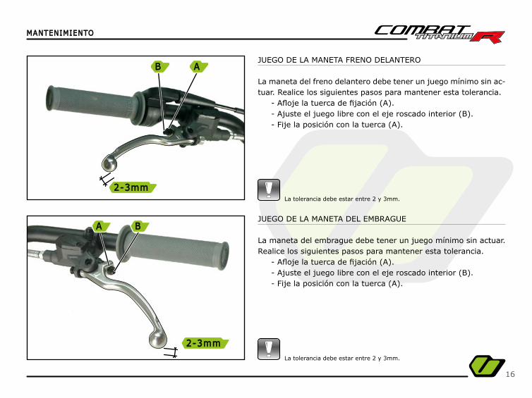
JUEGO DE LA MANETA FRENO DELANTERO
La maneta del freno delantero debe tener un juego mínimo sin ac-tuar. Realice los siguientes pasos para mantener esta tolerancia.
- Afl oje la tuerca de fi jación (A).- Ajuste el juego libre con el eje roscado interior (B).- Fije la posición con la tuerca (A).
La tolerancia debe estar entre 2 y 3mm.
JUEGO DE LA MANETA DEL EMBRAGUE
La maneta del embrague debe tener un juego mínimo sin actuar. Realice los siguientes pasos para mantener esta tolerancia.
- Afl oje la tuerca de fi jación (A).- Ajuste el juego libre con el eje roscado interior (B).- Fije la posición con la tuerca (A).
La tolerancia debe estar entre 2 y 3mm.
B
2-3mm2-3mm
A
A
2-3mm2-3mm
B
17
MANTENIMIENTOMANTENIMIENTO
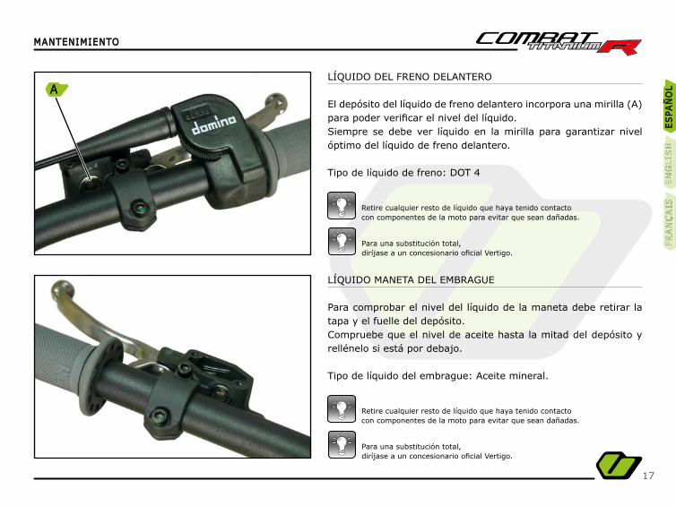
LÍQUIDO MANETA DEL EMBRAGUE
Para comprobar el nivel del líquido de la maneta debe retirar la tapa y el fuelle del depósito.Compruebe que el nivel de aceite hasta la mitad del depósito y rellénelo si está por debajo.
Tipo de líquido del embrague: Aceite mineral.
LÍQUIDO DEL FRENO DELANTERO
El depósito del líquido de freno delantero incorpora una mirilla (A) para poder verifi car el nivel del líquido.Siempre se debe ver líquido en la mirilla para garantizar nivel óptimo del líquido de freno delantero.
Tipo de líquido de freno: DOT 4
Para una substitución total,diríjase a un concesionario ofi cial Vertigo.
Para una substitución total,diríjase a un concesionario ofi cial Vertigo.
Retire cualquier resto de líquido que haya tenido contactocon componentes de la moto para evitar que sean dañadas.
Retire cualquier resto de líquido que haya tenido contactocon componentes de la moto para evitar que sean dañadas.
ES
PA
ÑO
LE
SPA
ÑO
LE
NG
LIS
HE
NG
LIS
HFR
AN
ÇA
ISFR
AN
ÇA
IS
A
18
MANTENIMIENTOMANTENIMIENTO
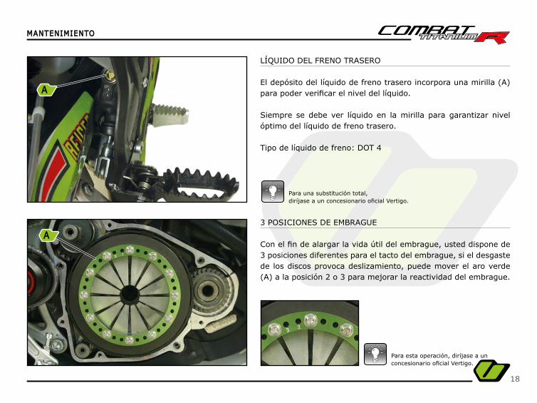
LÍQUIDO DEL FRENO TRASERO
El depósito del líquido de freno trasero incorpora una mirilla (A) para poder verifi car el nivel del líquido.
Siempre se debe ver líquido en la mirilla para garantizar nivel óptimo del líquido de freno trasero.
Tipo de líquido de freno: DOT 4
Para una substitución total,diríjase a un concesionario ofi cial Vertigo.
3 POSICIONES DE EMBRAGUE
Con el fi n de alargar la vida útil del embrague, usted dispone de 3 posiciones diferentes para el tacto del embrague, si el desgaste de los discos provoca deslizamiento, puede mover el aro verde (A) a la posición 2 o 3 para mejorar la reactividad del embrague.
Para esta operación, diríjase a unconcesionario ofi cial Vertigo.
A
A
19
MANTENIMIENTOMANTENIMIENTO
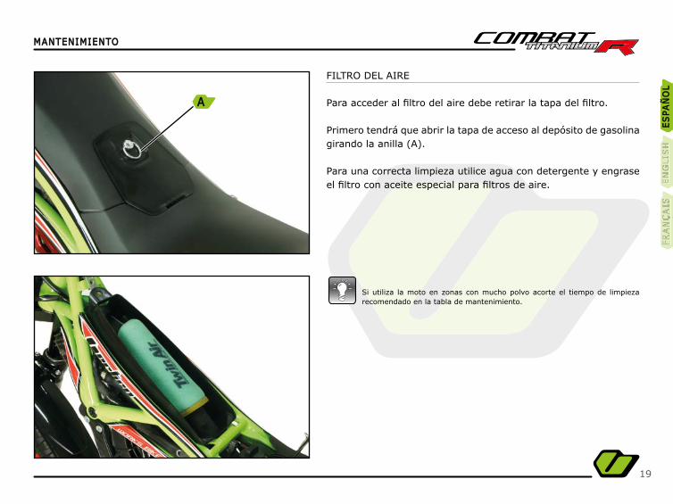
FILTRO DEL AIRE
Para acceder al fi ltro del aire debe retirar la tapa del fi ltro.
Primero tendrá que abrir la tapa de acceso al depósito de gasolina girando la anilla (A).
Para una correcta limpieza utilice agua con detergente y engrase el fi ltro con aceite especial para fi ltros de aire.
Si utiliza la moto en zonas con mucho polvo acorte el tiempo de limpieza recomendado en la tabla de mantenimiento.
ES
PA
ÑO
LE
SPA
ÑO
LE
NG
LIS
HE
NG
LIS
HFR
AN
ÇA
ISFR
AN
ÇA
IS
A
20
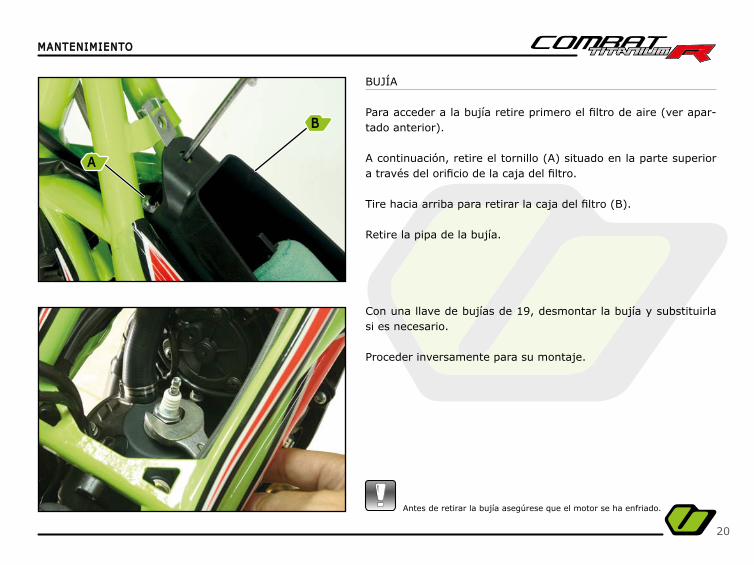
BUJÍA
Para acceder a la bujía retire primero el fi ltro de aire (ver apar-tado anterior).
A continuación, retire el tornillo (A) situado en la parte superior a través del orifi cio de la caja del fi ltro.
Tire hacia arriba para retirar la caja del fi ltro (B).
Retire la pipa de la bujía.
Con una llave de bujías de 19, desmontar la bujía y substituirla si es necesario.
Proceder inversamente para su montaje.
MANTENIMIENTOMANTENIMIENTO
Antes de retirar la bujía asegúrese que el motor se ha enfriado.
B
A
21
MANTENIMIENTOMANTENIMIENTO
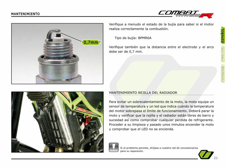
MANTENIMIENTO REJILLA DEL RADIADOR
Para evitar un sobrecalentamiento de la moto, la moto equipa un sensor de temperatura y un led que indica cuándo la temperatura del motor sobrepasa el límite de funcionamiento. Deberá parar la moto y verifi car que la rejilla y el radiador están libres de barro y suciedad así como comprobar cualquier perdida de refrigerante. Proceder a su limpieza y pasado unos minutos encender la moto y comprobar que el LED no se encienda.
Verifi que a menudo el estado de la bujía para saber si el motor realiza correctamente la combustión.
Tipo de bujía: BPMR6A
Verifi que también que la distancia entre el electrodo y el arco debe ser de 0,7 mm.
Si el problema persiste, diríjase a nuestra red de concesionariospara su reparación.
ES
PA
ÑO
LE
SPA
ÑO
LE
NG
LIS
HE
NG
LIS
HFR
AN
ÇA
ISFR
AN
ÇA
IS
0,7mm0,7mm
22
MANTENIMIENTOMANTENIMIENTO
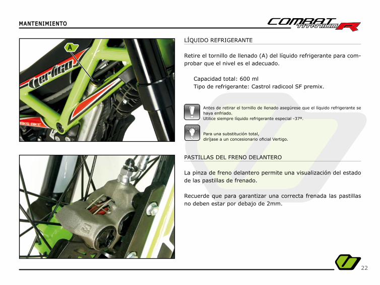
Antes de retirar el tornillo de llenado asegúrese que el líquido refrigerante se haya enfriado.Utilice siempre líquido refrigerante especial -37º.
Para una substitución total,diríjase a un concesionario ofi cial Vertigo.
LÍQUIDO REFRIGERANTE
Retire el tornillo de llenado (A) del líquido refrigerante para com-probar que el nivel es el adecuado.
Capacidad total: 600 mlTipo de refrigerante: Castrol radicool SF premix.
PASTILLAS DEL FRENO DELANTERO
La pinza de freno delantero permite una visualización del estado de las pastillas de frenado.
Recuerde que para garantizar una correcta frenada las pastillas no deben estar por debajo de 2mm.
A
23
MANTENIMIENTOMANTENIMIENTO
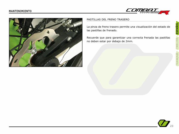
PASTILLAS DEL FRENO TRASERO
La pinza de freno trasero permite una visualización del estado de las pastillas de frenado.
Recuerde que para garantizar una correcta frenada las pastillas no deben estar por debajo de 2mm.
ES
PA
ÑO
LE
SPA
ÑO
LE
NG
LIS
HE
NG
LIS
HFR
AN
ÇA
ISFR
AN
ÇA
IS
24
MANTENIMIENTOMANTENIMIENTO
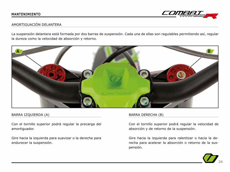
BARRA IZQUIERDA (A)
Con el tornillo superior podrá regular la precarga del amortiguador.
Gire hacia la izquierda para suavizar o la derecha para endurecer la suspensión.
BARRA DERECHA (B)
Con el tornillo superior podrá regular la velocidad de absorción y de retorno de la suspensión.
Gire hacia la izquierda para ralentizar o hacia la de-recha para acelerar la absorción o retorno de la sus-pensión.
AMORTIGUACIÓN DELANTERA
La suspensión delantera está formada por dos barras de suspensión. Cada una de ellas son regulables permitiendo así, regular la dureza como la velocidad de absorción y retorno.
A B
25
MANTENIMIENTOMANTENIMIENTO
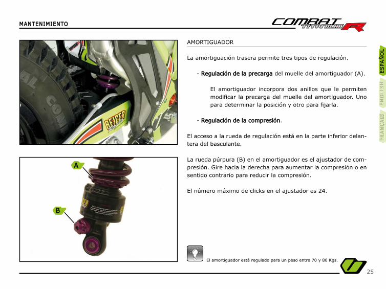
El amortiguador está regulado para un peso entre 70 y 80 Kgs.
ES
PA
ÑO
LE
SPA
ÑO
LE
NG
LIS
HE
NG
LIS
HFR
AN
ÇA
ISFR
AN
ÇA
IS
A
B
AMORTIGUADOR
La amortiguación trasera permite tres tipos de regulación.
- Regulación de la precargaRegulación de la precarga del muelle del amortiguador (A).
El amortiguador incorpora dos anillos que le permiten modifi car la precarga del muelle del amortiguador. Uno para determinar la posición y otro para fi jarla.
- Regulación de la compresiónRegulación de la compresión.
El acceso a la rueda de regulación está en la parte inferior delan-tera del basculante.
La rueda púrpura (B) en el amortiguador es el ajustador de com-presión. Gire hacia la derecha para aumentar la compresión o en sentido contrario para reducir la compresión.
El número máximo de clicks en el ajustador es 24.
26
MANTENIMIENTOMANTENIMIENTO
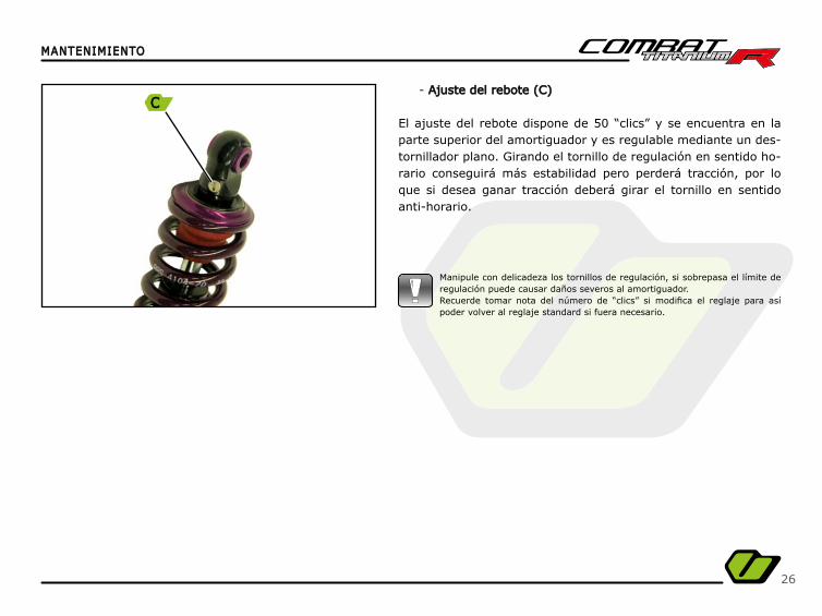
- Ajuste del rebote (C)Ajuste del rebote (C)
El ajuste del rebote dispone de 50 “clics” y se encuentra en la parte superior del amortiguador y es regulable mediante un des-tornillador plano. Girando el tornillo de regulación en sentido ho-rario conseguirá más estabilidad pero perderá tracción, por lo que si desea ganar tracción deberá girar el tornillo en sentido anti-horario.
Manipule con delicadeza los tornillos de regulación, si sobrepasa el límite de regulación puede causar daños severos al amortiguador. Recuerde tomar nota del número de “clics” si modifi ca el reglaje para así poder volver al reglaje standard si fuera necesario.
C
27
MANTENIMIENTOMANTENIMIENTO
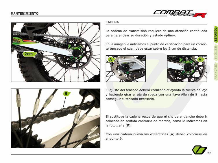
CADENA
La cadena de transmisión requiere de una atención continuada para garantizar su duración y estado óptimo.
En la imagen le indicamos el punto de verifi cación para un correc-to tensado el cual, debe estar sobre los 2 cm de distancia.
El ajuste del tensado deberá realizarlo afl ojando la tuerca del eje y haciendo girar el eje de rueda con una llave Allen de 8 hasta conseguir el tensado necesario.
Si sustituye la cadena recuerde que el clip de enganche debe ir colocado en sentido contrario de marcha, como le indicamos en la fotografía (B).
Con una cadena nueva las excéntricas (A) deben colocarse en el punto 9.
ES
PA
ÑO
LE
SPA
ÑO
LE
NG
LIS
HE
NG
LIS
HFR
AN
ÇA
ISFR
AN
ÇA
IS
2cm2cm
B
A A

28
MANTENIMIENTOMANTENIMIENTO
NEUMÁTICOS
Mantenga los neumáticos en buen estado y con la presión ade-cuada para garantizar una buena adherencia y evitar posibles caídas.
Neumático delantero:Medida: 1,60 x 21”Presión: 0,4 bar
ACEITE DEL MOTOR
La tapa del cárter derecho incorpora una mirilla para facilitar la comprobación del nivel del aceite del motor.
En la parte superior encontrará el tapón de llenado.
Capacidad total: 375 mlTipo de aceite: CASTROL TRANSMAX Z
Para una substitución total,diríjase a un concesionario ofi cial Vertigo.
Moto equipada con neumáticos de categoría especial.
Neumático trasero:Medida: 2,15 x 18” Presión: 0,3 bar
29
MANTENIMIENTOMANTENIMIENTO
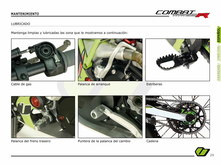
LUBRICADO
Mantenga limpias y lubricadas las zona que le mostramos a continuación:
Cable de gas
Palanca del freno trasero
Palanca de arranque
Puntera de la palanca del cambio
Estriberas
Cadena
ES
PA
ÑO
LE
SPA
ÑO
LE
NG
LIS
HE
NG
LIS
HFR
AN
ÇA
ISFR
AN
ÇA
IS
30
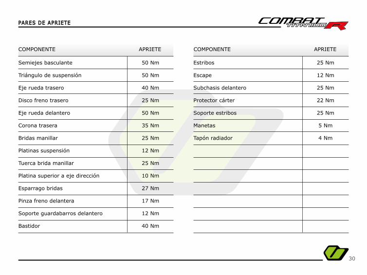
PARES DE APRIETEPARES DE APRIETE
COMPONENTE COMPONENTEAPRIETE APRIETE
Semiejes basculante
Triángulo de suspensión
Eje rueda trasero
Disco freno trasero
Eje rueda delantero
Corona trasera
Bridas manillar
Platinas suspensión
Tuerca brida manillar
Platina superior a eje dirección
Esparrago bridas
Pinza freno delantera
Soporte guardabarros delantero
Bastidor
Estribos
Escape
Subchasis delantero
Protector cárter
Soporte estribos
Manetas
Tapón radiador
50 Nm
50 Nm
40 Nm
25 Nm
50 Nm
35 Nm
25 Nm
12 Nm
25 Nm
10 Nm
27 Nm
17 Nm
12 Nm
40 Nm
25 Nm
12 Nm
25 Nm
22 Nm
25 Nm
5 Nm
4 Nm
31
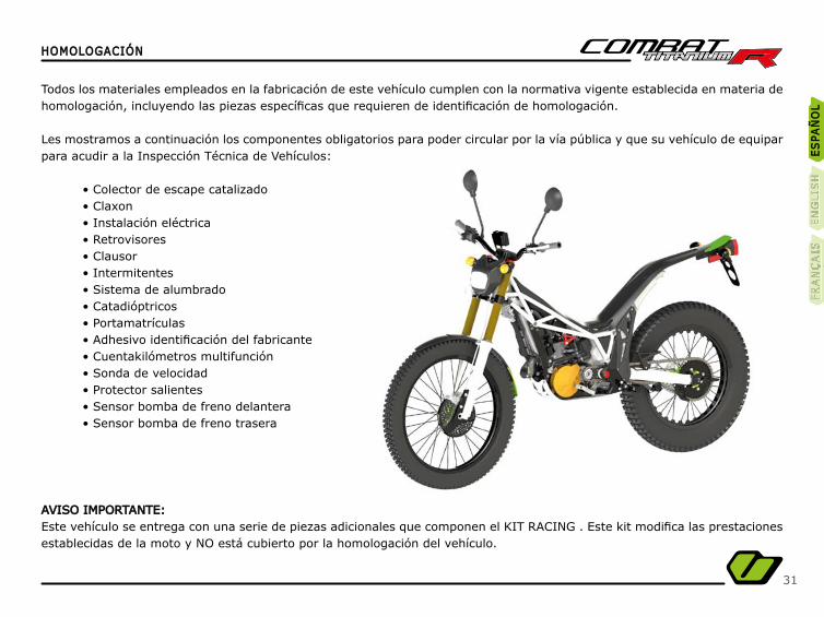
HOMOLOGACIÓNHOMOLOGACIÓN
Todos los materiales empleados en la fabricación de este vehículo cumplen con la normativa vigente establecida en materia de homologación, incluyendo las piezas específi cas que requieren de identifi cación de homologación.
Les mostramos a continuación los componentes obligatorios para poder circular por la vía pública y que su vehículo de equipar para acudir a la Inspección Técnica de Vehículos:
• Colector de escape catalizado• Claxon• Instalación eléctrica• Retrovisores• Clausor• Intermitentes• Sistema de alumbrado• Catadióptricos• Portamatrículas• Adhesivo identifi cación del fabricante• Cuentakilómetros multifunción• Sonda de velocidad• Protector salientes• Sensor bomba de freno delantera• Sensor bomba de freno trasera
AVISO IMPORTANTE:AVISO IMPORTANTE:Este vehículo se entrega con una serie de piezas adicionales que componen el KIT RACING . Este kit modifi ca las prestaciones establecidas de la moto y NO está cubierto por la homologación del vehículo.
ES
PA
ÑO
LE
SPA
ÑO
LE
NG
LIS
HE
NG
LIS
HFR
AN
ÇA
ISFR
AN
ÇA
IS
32
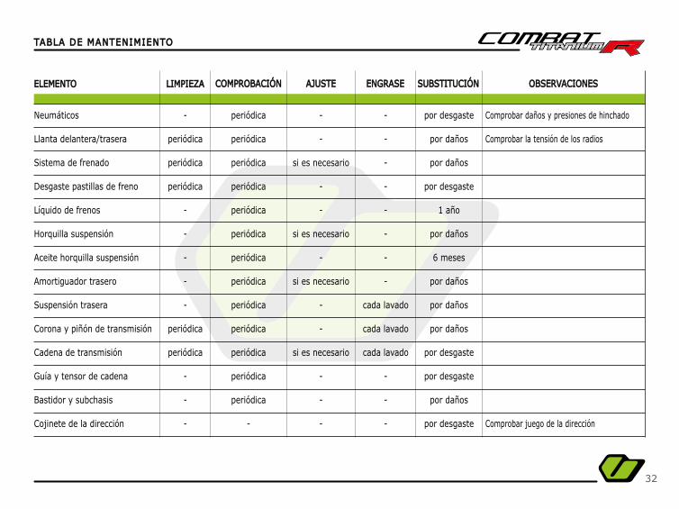
TABLA DE MANTENIMIENTOTABLA DE MANTENIMIENTO
ELEMENTOELEMENTO LIMPIEZALIMPIEZA COMPROBACIÓNCOMPROBACIÓN AJUSTEAJUSTE ENGRASEENGRASE SUBSTITUCIÓNSUBSTITUCIÓN OBSERVACIONESOBSERVACIONES
Neumáticos
Llanta delantera/trasera
Sistema de frenado
Desgaste pastillas de freno
Líquido de frenos
Horquilla suspensión
Aceite horquilla suspensión
Amortiguador trasero
Suspensión trasera
Corona y piñón de transmisión
Cadena de transmisión
Guía y tensor de cadena
Bastidor y subchasis
Cojinete de la dirección
Comprobar daños y presiones de hinchado
Comprobar la tensión de los radios
Comprobar juego de la dirección
-
periódica
periódica
periódica
-
-
-
-
-
periódica
periódica
-
-
-
periódica
periódica
periódica
periódica
periódica
periódica
periódica
periódica
periódica
periódica
periódica
periódica
periódica
-
-
-
si es necesario
-
-
si es necesario
-
si es necesario
-
-
si es necesario
-
-
-
-
-
-
-
-
-
-
-
cada lavado
cada lavado
cada lavado
-
-
-
por desgaste
por daños
por daños
por desgaste
1 año
por daños
6 meses
por daños
por daños
por daños
por desgaste
por desgaste
por daños
por desgaste
33
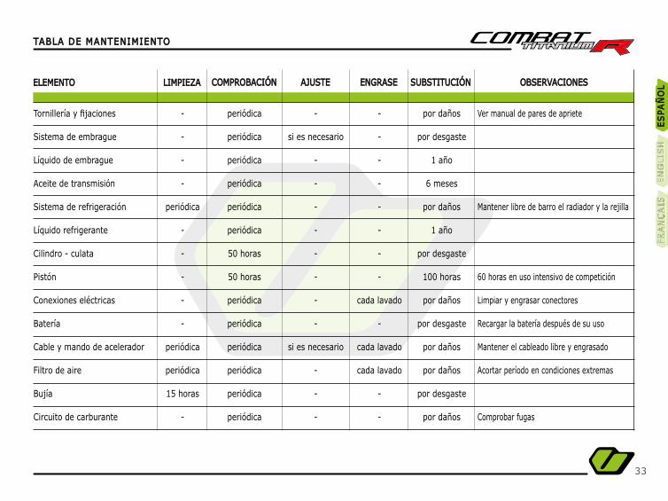
TABLA DE MANTENIMIENTOTABLA DE MANTENIMIENTO
ELEMENTOELEMENTO LIMPIEZALIMPIEZA COMPROBACIÓNCOMPROBACIÓN AJUSTEAJUSTE ENGRASEENGRASE SUBSTITUCIÓNSUBSTITUCIÓN OBSERVACIONESOBSERVACIONES
Tornillería y fi jaciones
Sistema de embrague
Líquido de embrague
Aceite de transmisión
Sistema de refrigeración
Líquido refrigerante
Cilindro - culata
Pistón
Conexiones eléctricas
Batería
Cable y mando de acelerador
Filtro de aire
Bujía
Circuito de carburante
Ver manual de pares de apriete
Mantener libre de barro el radiador y la rejilla
60 horas en uso intensivo de competición
Limpiar y engrasar conectores
Recargar la batería después de su uso
Mantener el cableado libre y engrasado
Acortar período en condiciones extremas
Comprobar fugas
-
-
-
-
periódica
-
-
-
-
-
periódica
periódica
15 horas
-
periódica
periódica
periódica
periódica
periódica
periódica
50 horas
50 horas
periódica
periódica
periódica
periódica
periódica
periódica
-
si es necesario
-
-
-
-
-
-
-
-
si es necesario
-
-
-
-
-
-
-
-
-
-
-
cada lavado
-
cada lavado
cada lavado
-
-
por daños
por desgaste
1 año
6 meses
por daños
1 año
por desgaste
100 horas
por daños
por desgaste
por daños
por daños
por desgaste
por daños
ES
PA
ÑO
LE
SPA
ÑO
LE
NG
LIS
HE
NG
LIS
HFR
AN
ÇA
ISFR
AN
ÇA
IS

34
DATOS TÉCNICOSDATOS TÉCNICOS
RUEDAS
DIMENSIONES
Altura asiento
Longitud total
Distancia entre ejes
Rueda delantera
Rueda trasera (mecanizada)
680 mm
2.010 mm
1.310 mm
1,60 x 21”
2,15 x 18”
0,4 bar
0,3 bar
Neumático
Neumático
Presión
Presión
Peso 69 kg
35
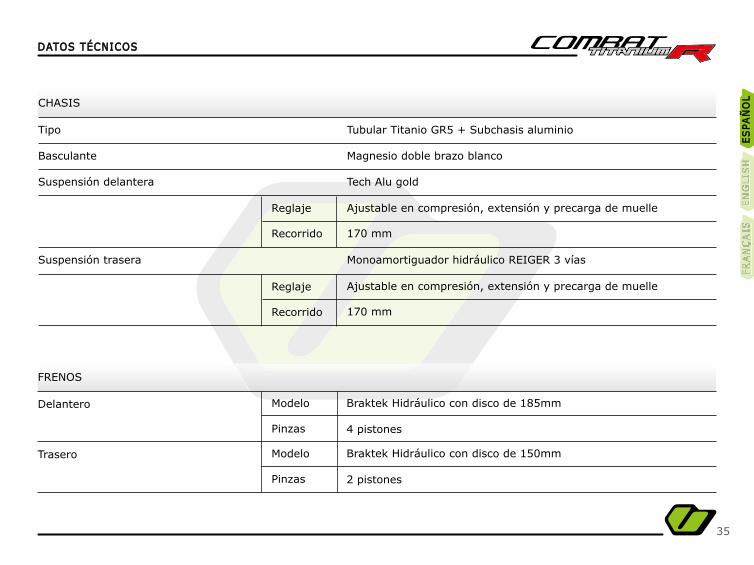
CHASIS
FRENOS
Tipo
Delantero
Trasero
Basculante
Suspensión delantera
Suspensión trasera
Tubular Titanio GR5 + Subchasis aluminio
Braktek Hidráulico con disco de 185mm
Braktek Hidráulico con disco de 150mm
Magnesio doble brazo blanco
4 pistones
2 pistones
Tech Alu gold
Monoamortiguador hidráulico REIGER 3 vías
Ajustable en compresión, extensión y precarga de muelle
Ajustable en compresión, extensión y precarga de muelle
170 mm
170 mm
Modelo
Reglaje
Reglaje
Modelo
Pinzas
Recorrido
Recorrido
Pinzas
DATOS TÉCNICOSDATOS TÉCNICOS
ES
PA
ÑO
LE
SPA
ÑO
LE
NG
LIS
HE
NG
LIS
HFR
AN
ÇA
ISFR
AN
ÇA
IS
36
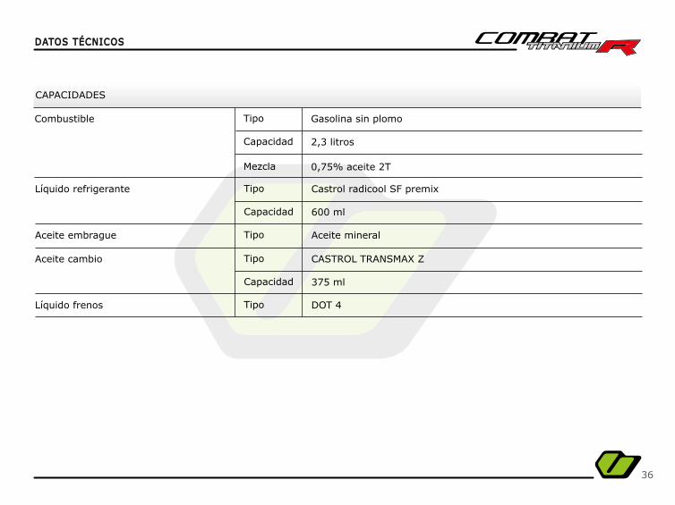
DATOS TÉCNICOSDATOS TÉCNICOS
CAPACIDADES
Líquido refrigerante
Combustible
Aceite embrague
Aceite cambio
Líquido frenos
600 ml
2,3 litros
0,75% aceite 2T
375 ml
Castrol radicool SF premix
Gasolina sin plomo
Aceite mineral
CASTROL TRANSMAX Z
DOT 4
Tipo
Tipo
Tipo
Tipo
Tipo
Capacidad
Capacidad
Mezcla
Capacidad
37
DATOS TÉCNICOSDATOS TÉCNICOS
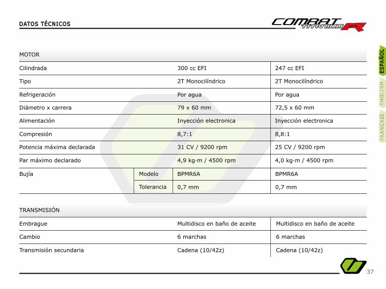
TRANSMISIÓN
Embrague
Cambio
Transmisión secundaria
Multidisco en baño de aceite Multidisco en baño de aceite
6 marchas 6 marchas
Cadena (10/42z) Cadena (10/42z)
MOTOR
Cilindrada
Tipo
Alimentación
Refrigeración
Compresión
Diámetro x carrera
Potencia máxima declarada
Par máximo declarado
Bujía
300 cc EFI 247 cc EFI
2T Monocilíndrico 2T Monocilíndrico
Inyección electronica Inyección electronica
Por agua Por agua
8,7:1 8,8:1
79 x 60 mm 72,5 x 60 mm
31 CV / 9200 rpm 25 CV / 9200 rpm
4,9 kg·m / 4500 rpm 4,0 kg·m / 4500 rpm
BPMR6A BPMR6A
0,7 mm 0,7 mm
Modelo
Tolerancia
ES
PA
ÑO
LE
SPA
ÑO
LE
NG
LIS
HE
NG
LIS
HFR
AN
ÇA
ISFR
AN
ÇA
IS

38
39
Congratulations on your choice !Congratulations on your choice !
We would like to welcome you to Vertigo Motors and share with you our experience and passion for trial motorbikes,We would like to welcome you to Vertigo Motors and share with you our experience and passion for trial motorbikes,design, technology, innovation and research.design, technology, innovation and research.
Vertigo was born out of a desire to see trial motorbikes evolve and to take them to the next level.
At Vertigo we dream about the ideal bike for practising our passion, without distinctions between amateur or professionals,a revolutionary motorbike, designed with you in mind.
Now you have become a part of our team, joining in with the best technical team, riders and motorbike enthusiasts,and the best professionals in each speciality. All with a common denominator: Passion and Experience.Passion and Experience.
In Vertigo, we also offer you the possibility of practising trial riding in a reserved private area (Noassar)(Noassar),located in Camprodon within the Puig-Franco Hotel Resort, in which to enjoy your passion for trials.
For further information, visit the website: www.puigfranco.eswww.puigfranco.es
With this manual we provide the details, maintenance tasks and basic settings that you can apply yourself to your new Vertigo.Also at your offi cial Vertigo Motors Dealership you will fi nd a team of experts who can advise you on all matters related to
your motorcycle and its accessories.
We invite you to form a part of our history and our success.
Vertigo Motors reserves the right to carry out changes and/or modifi cations to its models without prior notifi cation.
ES
PA
ÑO
LÑ
ES
PA
ÑÑÑÑO
LE
SPA
ÑÑO
LE
NG
LIS
HE
NG
LIS
HFR
AN
ÇA
ISFR
AN
ÇA
IS

40
41
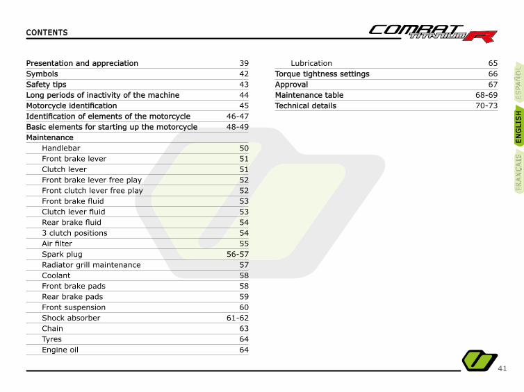
CONTENTSCONTENTS
Presentation and appreciationPresentation and appreciationSymbolsSymbolsSafety tipsSafety tipsLong periods of inactivity of the machineLong periods of inactivity of the machineMotorcycle identifi cationMotorcycle identifi cationIdentifi cation of elements of the motorcycleIdentifi cation of elements of the motorcycleBasic elements for starting up the motorcycleBasic elements for starting up the motorcycleMaintenanceMaintenance
HandlebarFront brake leverClutch leverFront brake lever free playFront clutch lever free playFront brake fl uidClutch lever fl uidRear brake fl uid3 clutch positionsAir fi lterSpark plugRadiator grill maintenanceCoolantFront brake padsRear brake padsFront suspensionShock absorberChainTyresEngine oil
3942434445
46-4748-49
50515152525353545455
56-575758585960
61-62636464
656667
68-6970-73
LubricationTorque tightness settingsTorque tightness settingsApprovalApprovalMaintenance tableMaintenance tableTechnical detailsTechnical details
ES
PA
ÑO
LÑ
ES
PA
ÑÑÑÑO
LE
SPA
ÑÑO
LE
NG
LIS
HE
NG
LIS
HFR
AN
ÇA
ISFR
AN
ÇA
IS
42
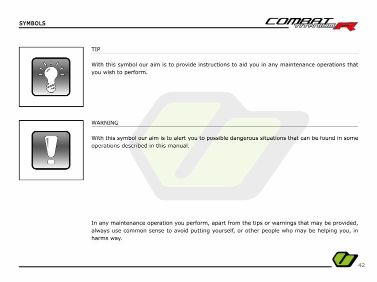
TIP
With this symbol our aim is to provide instructions to aid you in any maintenance operations that you wish to perform.
WARNING
With this symbol our aim is to alert you to possible dangerous situations that can be found in some operations described in this manual.
In any maintenance operation you perform, apart from the tips or warnings that may be provided, always use common sense to avoid putting yourself, or other people who may be helping you, in harms way.
SYMBOLSSYMBOLS
43
Before using this motorcycle make yourself familiar with it, taking time to identify all the basic elements for riding it.
Read each and every one of the sections in this manual carefully.
This motorcycle has been manufactured exclusively for trials riding, as it is not been designed to carry a pillion passenger.
Perform the maintenance operations described in this manual and at the time indicated, so that your remains in good condition as long as possible.
Use equipment suitable for practising trial riding that guarantees your safety (helmet, clothing, protections, etc.).
Use the motorcycle progressively until its maximum performance is attained.
Avoid starting the motorcycle with the stand down.
SAFETY TIPSSAFETY TIPS
ES
PA
ÑO
LÑ
ES
PA
ÑÑÑÑO
LE
SPA
ÑÑO
LE
NG
LIS
HE
NG
LIS
HFR
AN
ÇA
ISFR
AN
ÇA
IS
44
Certain measures need to be taken to ensure the proper maintenance of the motorbike in the event of the machine undergoing long periods of inactivity:
- Clean the bike completely before storing it.
- Reduce the pressure in the tyres.
- Protect the bike with a cover to prevent dust and dirt from settling.
LONG PERIODS OF INACTIVITY OF THE MACHINELONG PERIODS OF INACTIVITY OF THE MACHINE
45
MOTORCYCLE IDENTIFICATIONMOTORCYCLE IDENTIFICATION
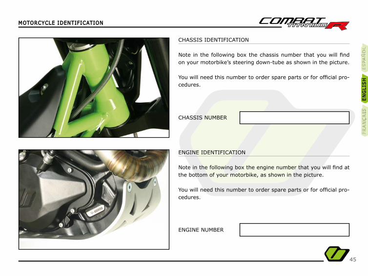
CHASSIS IDENTIFICATION
Note in the following box the chassis number that you will fi nd on your motorbike’s steering down-tube as shown in the picture.
You will need this number to order spare parts or for offi cial pro-cedures.
CHASSIS NUMBER
ENGINE NUMBER
ENGINE IDENTIFICATION
Note in the following box the engine number that you will fi nd at the bottom of your motorbike, as shown in the picture.
You will need this number to order spare parts or for offi cial pro-cedures.
ES
PA
ÑO
LÑ
ES
PA
ÑÑÑÑO
LE
SPA
ÑÑO
LE
NG
LIS
HE
NG
LIS
HFR
AN
ÇA
ISFR
AN
ÇA
IS

46
IDENTIFICATION OF ELEMENTS OF THE MOTORCYCLEIDENTIFICATION OF ELEMENTS OF THE MOTORCYCLE
RIGHT-HAND SIDE VIEW
Identify the following elements on your motorbike in order to familiarise yourself with it before starting up.
Exhaust
Stop button
Radiator cap
Kick-start lever
Rear brake pedal
Rear brake disk
1 3 52 4 6
56 4
1
3
2
47
IDENTIFICATION OF ELEMENTS OF THE MOTORCYCLEIDENTIFICATION OF ELEMENTS OF THE MOTORCYCLE
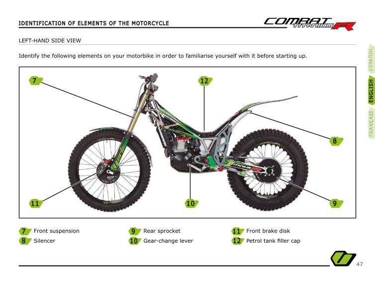
LEFT-HAND SIDE VIEW
Identify the following elements on your motorbike in order to familiarise yourself with it before starting up.
Front suspension
Silencer
Rear sprocket
Gear-change lever
Front brake disk
Petrol tank fi ller cap
7 9 11118 12121010
ES
PA
ÑO
LÑ
ES
PA
ÑÑÑÑO
LE
SPA
ÑÑO
LE
NG
LIS
HE
NG
LIS
HFR
AN
ÇA
ISFR
AN
ÇA
IS
7 1212
1111 1010 9
8

48
FUEL TANK
Access to the petrol tank is in the middle of the motorbike.
Turn the ring (A) to the left and pull the cover back to access the fi ller cap.
Always use 95 octane or 98 octane petrol with a mixture of0.75% 2-stroke oil.
Remove any petrol remains that may have come into contactwith the machine’s components so that they are not damaged.
BASIC ELEMENTS FOR STARTING UP THE MOTORCYCLEBASIC ELEMENTS FOR STARTING UP THE MOTORCYCLE
A
49
BASIC ELEMENTS FOR STARTING UP THE MOTORCYCLEBASIC ELEMENTS FOR STARTING UP THE MOTORCYCLE
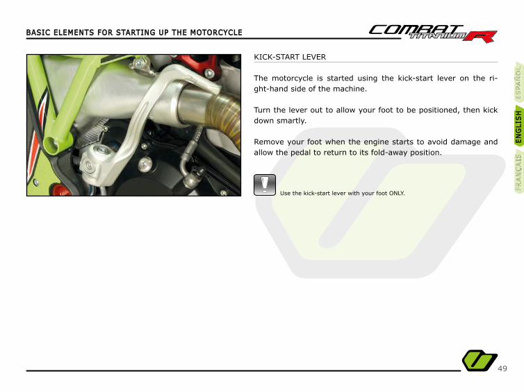
KICK-START LEVER
The motorcycle is started using the kick-start lever on the ri-ght-hand side of the machine.
Turn the lever out to allow your foot to be positioned, then kick down smartly.
Remove your foot when the engine starts to avoid damage and allow the pedal to return to its fold-away position.
Use the kick-start lever with your foot ONLY.
ES
PA
ÑO
LÑ
ES
PA
ÑÑÑÑO
LE
SPA
ÑÑO
LE
NG
LIS
HE
NG
LIS
HFR
AN
ÇA
ISFR
AN
ÇA
IS

50
MAINTENANCEMAINTENANCE
Adjusting the handlebar distance.the handlebar distance.
The handlebar clamps have 4 different positions to adapt accor-ding to your requirements.
Inverting the position of the handlebar clamps can either bring the handlebar closer or move them further away.
Modifying the handlebar clamps anchor to the plate with two po-sitions available allows you to move the handlebar closer or fur-ther away.
HANDLEBAR
Adjusting the inclination of the handlebarthe inclination of the handlebar so that is best suits your style of riding.
- Loosen the 4 bolts (A).- Place the handlebar in the position that is most suitable for you.- Re-tighten the 4 bolts (A).
Tighten the four bolts cross-wise and equally.We recommend you adjust the controls on the handlebars.
Make sure that the bolts are tightened to the torque shownin the tightening table to avoid any possible accidents.
Ensure the handlebar are centred before tightening the bolts.
A
51
MAINTENANCEMAINTENANCE
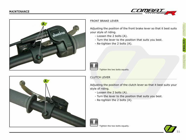
FRONT BRAKE LEVER
Adjusting the position of the front brake lever so that it best suits your style of riding.
- Loosen the 2 bolts (A).- Turn the lever to the position that suits you best.- Re-tighten the 2 bolts (A).
Tighten the two bolts equally.
CLUTCH LEVER
Adjusting the position of the clutch lever so that it best suits your style of riding.
- Loosen the 2 bolts (A).- Turn the lever to the position that suits you best.- Re-tighten the 2 bolts (A).
Tighten the two bolts equally.
ES
PA
ÑO
LÑ
ES
PA
ÑÑÑÑO
LE
SPA
ÑÑO
LE
NG
LIS
HE
NG
LIS
HFR
AN
ÇA
ISFR
AN
ÇA
IS
A
A
52
MAINTENANCEMAINTENANCE
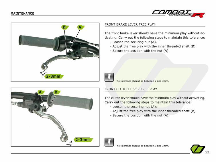
FRONT BRAKE LEVER FREE PLAY
The front brake lever should have the minimum play without ac-tivating. Carry out the following steps to maintain this tolerance:
- Loosen the securing nut (A).- Adjust the free play with the inner threaded shaft (B).- Secure the position with the nut (A).
The tolerance should be between 2 and 3mm.
FRONT CLUTCH LEVER FREE PLAY
The clutch lever should have the minimum play without activating.Carry out the following steps to maintain this tolerance:
- Loosen the securing nut (A).- Adjust the free play with the inner threaded shaft (B).- Secure the position with the nut (A).
The tolerance should be between 2 and 3mm.
B
2-3mm2-3mm
A
A
2-3mm2-3mm
B
53
MAINTENANCEMAINTENANCE
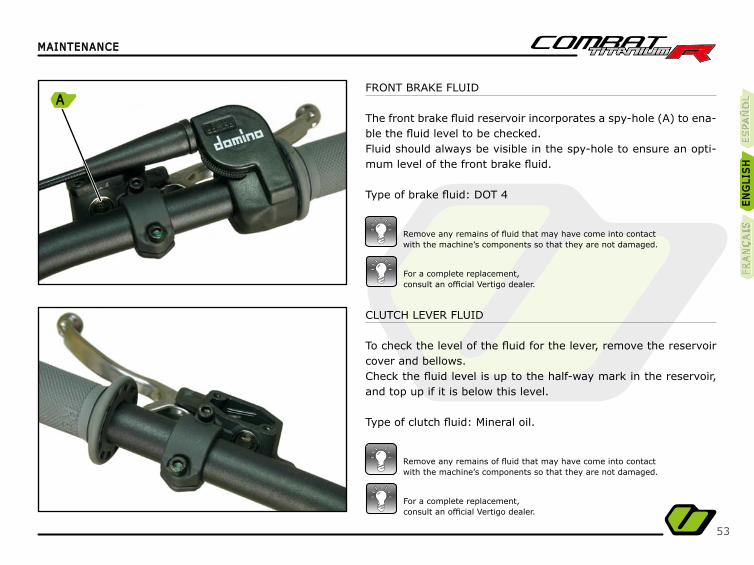
CLUTCH LEVER FLUID
To check the level of the fl uid for the lever, remove the reservoir cover and bellows.Check the fl uid level is up to the half-way mark in the reservoir, and top up if it is below this level.
Type of clutch fl uid: Mineral oil.
FRONT BRAKE FLUID
The front brake fl uid reservoir incorporates a spy-hole (A) to ena-ble the fl uid level to be checked.Fluid should always be visible in the spy-hole to ensure an opti-mum level of the front brake fl uid.
Type of brake fl uid: DOT 4
For a complete replacement,consult an offi cial Vertigo dealer.
For a complete replacement,consult an offi cial Vertigo dealer.
Remove any remains of fl uid that may have come into contactwith the machine’s components so that they are not damaged.
Remove any remains of fl uid that may have come into contactwith the machine’s components so that they are not damaged.
ES
PA
ÑO
LÑ
ES
PA
ÑÑÑÑO
LE
SPA
ÑÑO
LE
NG
LIS
HE
NG
LIS
HFR
AN
ÇA
ISFR
AN
ÇA
IS
A
54
MAINTENANCEMAINTENANCE
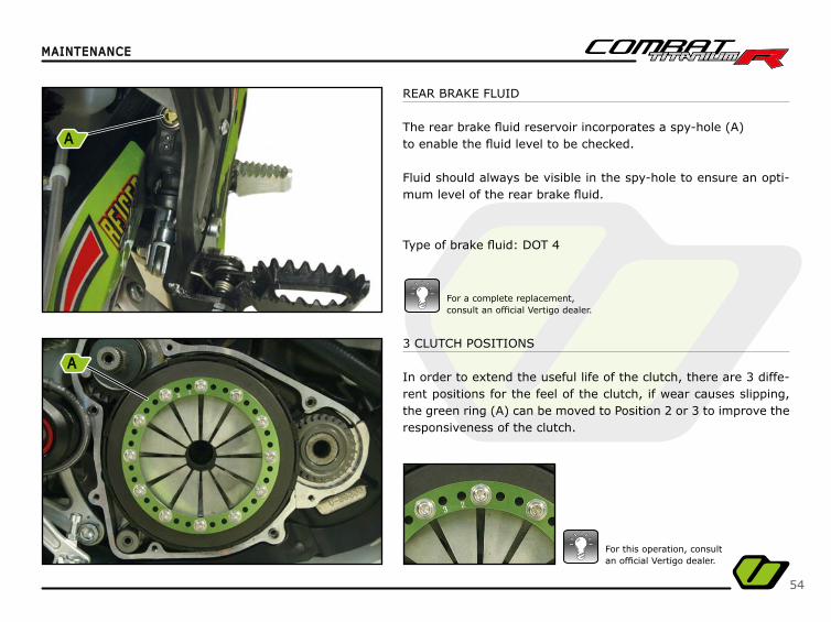
REAR BRAKE FLUID
The rear brake fl uid reservoir incorporates a spy-hole (A)to enable the fl uid level to be checked.
Fluid should always be visible in the spy-hole to ensure an opti-mum level of the rear brake fl uid.
Type of brake fl uid: DOT 4
For a complete replacement,consult an offi cial Vertigo dealer.
3 CLUTCH POSITIONS
In order to extend the useful life of the clutch, there are 3 diffe-rent positions for the feel of the clutch, if wear causes slipping, the green ring (A) can be moved to Position 2 or 3 to improve the responsiveness of the clutch.
For this operation, consultan offi cial Vertigo dealer.
A
A

55
MAINTENANCEMAINTENANCE
AIR FILTER
To access the air fi lter, remove the fi lter cover.
Firstly, open the cover to access the fuel tank by turning the ring (A).
To clean properly, use soapy water and lubricate the fi lter with a special oil for air fi lters.
If the machine is used in very dusty areas, clean more frequently than the times recommended in the maintenance table.
ES
PA
ÑO
LÑ
ES
PA
ÑÑÑÑO
LE
SPA
ÑÑO
LE
NG
LIS
HE
NG
LIS
HFR
AN
ÇA
ISFR
AN
ÇA
IS
A
56
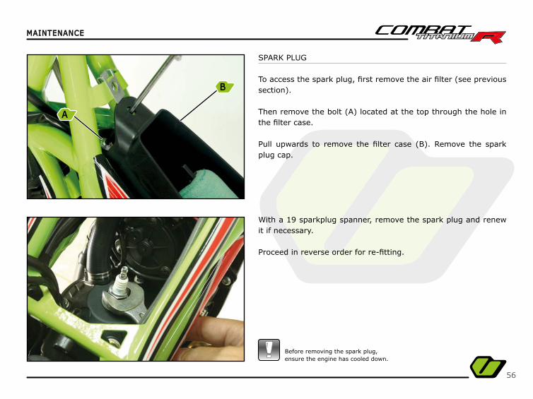
SPARK PLUG
To access the spark plug, fi rst remove the air fi lter (see previous section).
Then remove the bolt (A) located at the top through the hole in the fi lter case.
Pull upwards to remove the fi lter case (B). Remove the spark plug cap.
With a 19 sparkplug spanner, remove the spark plug and renew it if necessary.
Proceed in reverse order for re-fi tting.
MAINTENANCEMAINTENANCE
Before removing the spark plug,ensure the engine has cooled down.
B
A

57
MAINTENANCEMAINTENANCE
RADIATOR GRILL MAINTENANCE
To prevent it from overheating, the bike is equipped with a tem-perature sensor and an LED that indicates when the engine tem-perature exceeds the operating limit. The machine should be sto-pped and a check performed to ensure that the grille and radiator are free from dirt and mud, and that there is no loss of coolant. After cleaning it wait a few minutes then start up the motorcycle and check that the LED does not light up.
Inspect the condition of the spark plug frequently to check if the engine combustion is correct.
Type of spark plug: BPMR6A
Also check the gap between the electrode and the arc, which should be 0.7 mm.
If the problem persists, contact our networkof dealerships in order to repair it.
ES
PA
ÑO
LÑ
ES
PA
ÑÑÑÑO
LE
SPA
ÑÑO
LE
NG
LIS
HE
NG
LIS
HFR
AN
ÇA
ISFR
AN
ÇA
IS
0,7mm0,7mm
58
MAINTENANCEMAINTENANCE
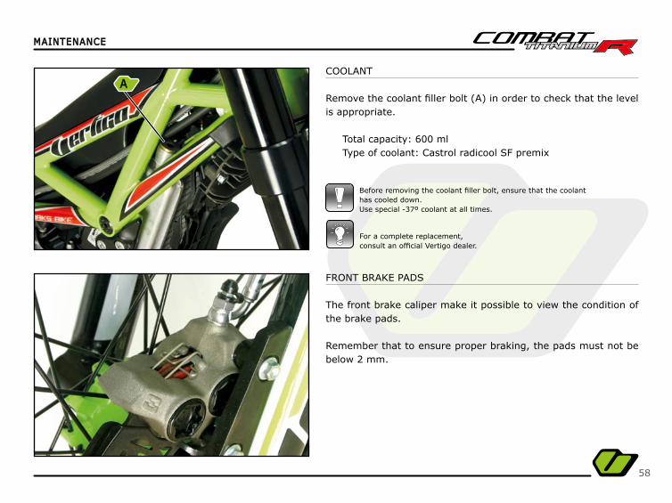
COOLANT
Remove the coolant fi ller bolt (A) in order to check that the level is appropriate.
Total capacity: 600 mlType of coolant: Castrol radicool SF premix
Before removing the coolant fi ller bolt, ensure that the coolanthas cooled down.Use special -37º coolant at all times.
For a complete replacement,consult an offi cial Vertigo dealer.
FRONT BRAKE PADS
The front brake caliper make it possible to view the condition of the brake pads.
Remember that to ensure proper braking, the pads must not be below 2 mm.
A
59
MAINTENANCEMAINTENANCE
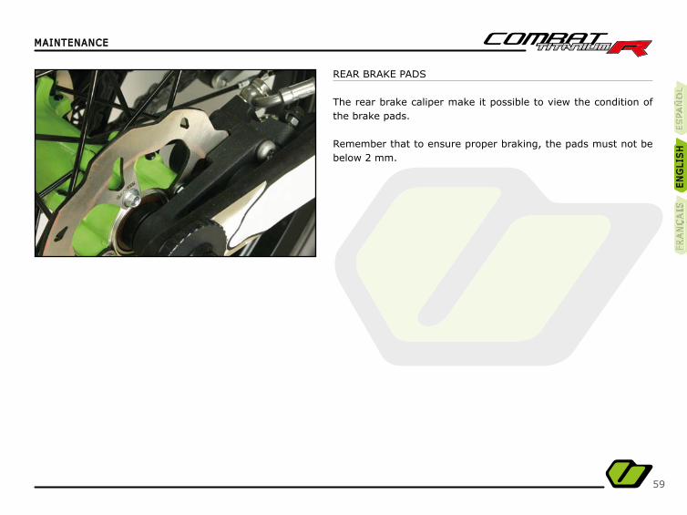
REAR BRAKE PADS
The rear brake caliper make it possible to view the condition of the brake pads.
Remember that to ensure proper braking, the pads must not be below 2 mm.
ES
PA
ÑO
LÑ
ES
PA
ÑÑÑÑO
LE
SPA
ÑÑO
LE
NG
LIS
HE
NG
LIS
HFR
AN
ÇA
ISFR
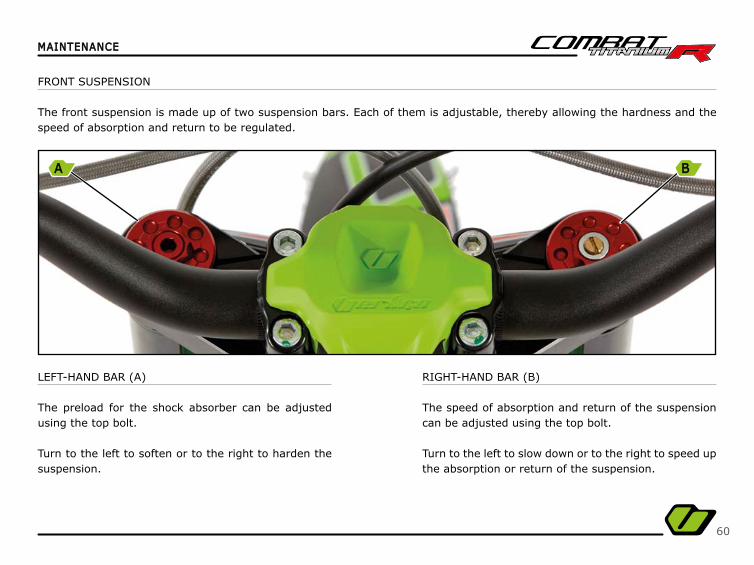
AN
ÇA
IS
60
MAINTENANCEMAINTENANCE
LEFT-HAND BAR (A)
The preload for the shock absorber can be adjusted using the top bolt.
Turn to the left to soften or to the right to harden the suspension.
RIGHT-HAND BAR (B)
The speed of absorption and return of the suspension can be adjusted using the top bolt.
Turn to the left to slow down or to the right to speed up the absorption or return of the suspension.
FRONT SUSPENSION
The front suspension is made up of two suspension bars. Each of them is adjustable, thereby allowing the hardness and the speed of absorption and return to be regulated.
A B
61
MAINTENANCEMAINTENANCE
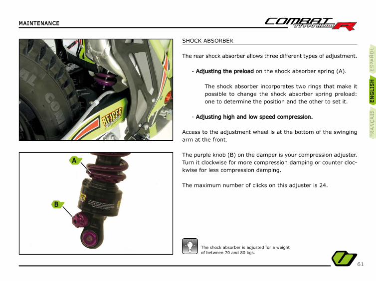
The shock absorber is adjusted for a weightof between 70 and 80 kgs.
ES
PA
ÑO
LÑ
ES
PA
ÑÑÑÑO
LE
SPA
ÑÑO
LE
NG
LIS
HE
NG
LIS
HFR
AN
ÇA
ISFR
AN
ÇA
IS
A
B
SHOCK ABSORBER
The rear shock absorber allows three different types of adjustment.
- Adjusting the preload Adjusting the preload on the shock absorber spring (A).
The shock absorber incorporates two rings that make it possible to change the shock absorber spring preload: one to determine the position and the other to set it.
- Adjusting high and low speed compression.Adjusting high and low speed compression.
Access to the adjustment wheel is at the bottom of the swinging arm at the front.
The purple knob (B) on the damper is your compression adjuster.Turn it clockwise for more compression damping or counter cloc-kwise for less compression damping.
The maximum number of clicks on this adjuster is 24.
62
MAINTENANCEMAINTENANCE
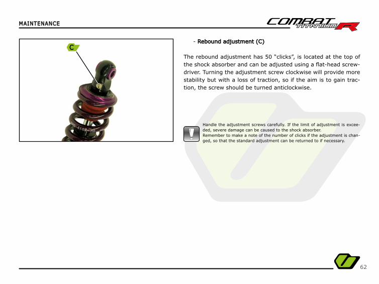
- Rebound adjustment (C)Rebound adjustment (C)
The rebound adjustment has 50 “clicks”, is located at the top of the shock absorber and can be adjusted using a fl at-head screw-driver. Turning the adjustment screw clockwise will provide more stability but with a loss of traction, so if the aim is to gain trac-tion, the screw should be turned anticlockwise.
Handle the adjustment screws carefully. If the limit of adjustment is excee-ded, severe damage can be caused to the shock absorber.Remember to make a note of the number of clicks if the adjustment is chan-ged, so that the standard adjustment can be returned to if necessary.
C
63
MAINTENANCEMAINTENANCE
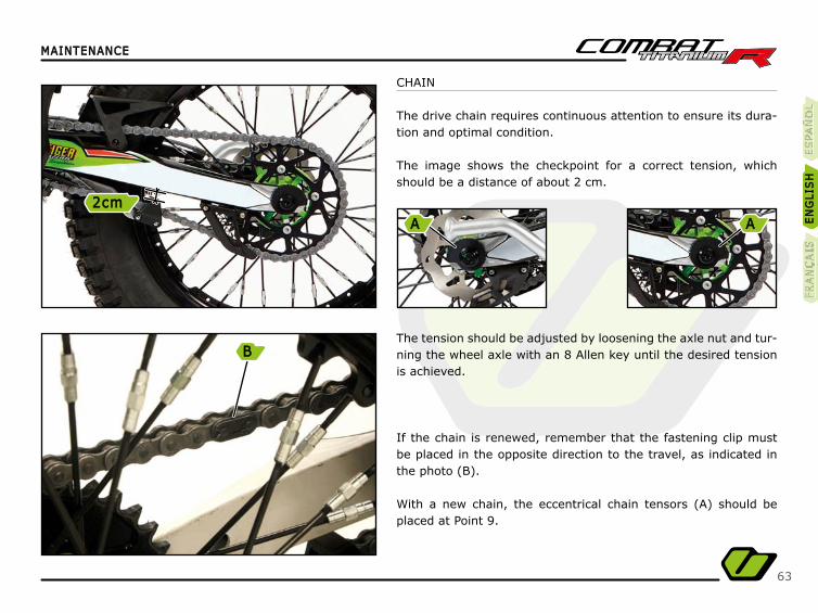
CHAIN
The drive chain requires continuous attention to ensure its dura-tion and optimal condition.
The image shows the checkpoint for a correct tension, which should be a distance of about 2 cm.
The tension should be adjusted by loosening the axle nut and tur-ning the wheel axle with an 8 Allen key until the desired tension is achieved.
If the chain is renewed, remember that the fastening clip must be placed in the opposite direction to the travel, as indicated in the photo (B).
With a new chain, the eccentrical chain tensors (A) should be placed at Point 9.
ES
PA
ÑO
LÑ
ES
PA
ÑÑÑÑO
LE
SPA
ÑÑO
LE
NG
LIS
HE
NG
LIS
HFR
AN
ÇA
ISFR
AN
ÇA
IS
B
2cm2cmA A
64
MAINTENANCEMAINTENANCE
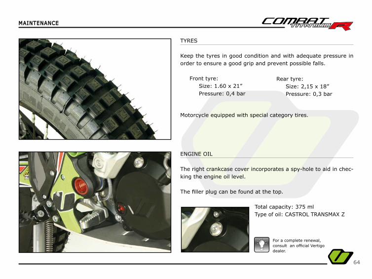
TYRES
Keep the tyres in good condition and with adequate pressure in order to ensure a good grip and prevent possible falls.
Front tyre:Size: 1.60 x 21”Pressure: 0,4 bar
ENGINE OIL
The right crankcase cover incorporates a spy-hole to aid in chec-king the engine oil level.
The fi ller plug can be found at the top.
Total capacity: 375 mlType of oil: CASTROL TRANSMAX Z
For a complete renewal, consult an offi cial Vertigo dealer.
Motorcycle equipped with special category tires.
Rear tyre:Size: 2,15 x 18” Pressure: 0,3 bar
65
MAINTENANCEMAINTENANCE
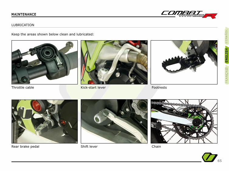
LUBRICATION
Keep the areas shown below clean and lubricated:
Throttle cable
Rear brake pedal
Kick-start lever
Shift lever
Footrests
Chain
ES
PA
ÑO
LÑ
ES
PA
ÑÑÑÑO
LE
SPA
ÑÑO
LE
NG
LIS
HE
NG
LIS
HFR
AN
ÇA
ISFR
AN
ÇA
IS
66
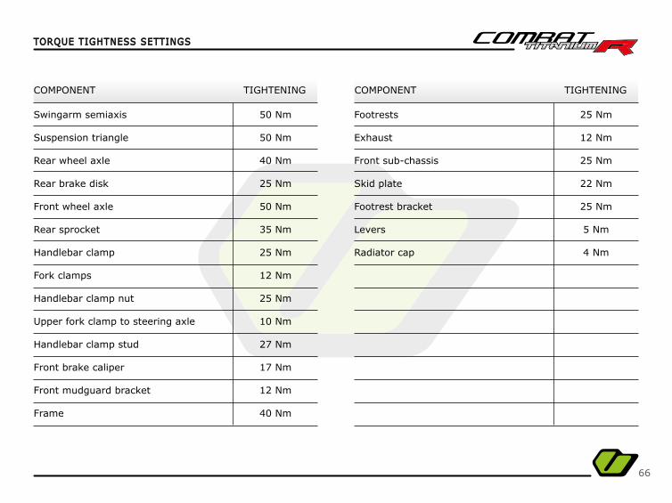
TORQUE TIGHTNESS SETTINGSTORQUE TIGHTNESS SETTINGS
COMPONENT COMPONENTTIGHTENING TIGHTENING
Swingarm semiaxis
Suspension triangle
Rear wheel axle
Rear brake disk
Front wheel axle
Rear sprocket
Handlebar clamp
Fork clamps
Handlebar clamp nut
Upper fork clamp to steering axle
Handlebar clamp stud
Front brake caliper
Front mudguard bracket
Frame
Footrests
Exhaust
Front sub-chassis
Skid plate
Footrest bracket
Levers
Radiator cap
50 Nm
50 Nm
40 Nm
25 Nm
50 Nm
35 Nm
25 Nm
12 Nm
25 Nm
10 Nm
27 Nm
17 Nm
12 Nm
40 Nm
25 Nm
12 Nm
25 Nm
22 Nm
25 Nm
5 Nm
4 Nm
67
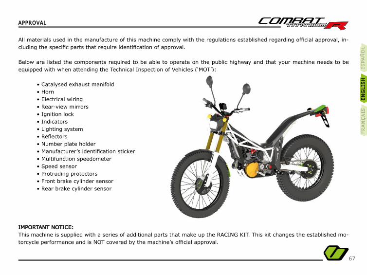
APPROVALAPPROVAL
All materials used in the manufacture of this machine comply with the regulations established regarding offi cial approval, in-cluding the specifi c parts that require identifi cation of approval.
Below are listed the components required to be able to operate on the public highway and that your machine needs to be equipped with when attending the Technical Inspection of Vehicles (‘MOT’):
• Catalysed exhaust manifold• Horn• Electrical wiring• Rear-view mirrors• Ignition lock• Indicators• Lighting system• Refl ectors• Number plate holder• Manufacturer’s identifi cation sticker• Multifunction speedometer• Speed sensor• Protruding protectors• Front brake cylinder sensor• Rear brake cylinder sensor
IMPORTANT NOTICE:IMPORTANT NOTICE:This machine is supplied with a series of additional parts that make up the RACING KIT. This kit changes the established mo-torcycle performance and is NOT covered by the machine’s offi cial approval.
ES
PA
ÑO
LÑ
ES
PA
ÑÑÑÑO
LE
SPA
ÑÑÑO
LE
NG
LIS
HE
NG
LIS
HFR
AN
ÇA
ISFR
AN
ÇA
IS
68
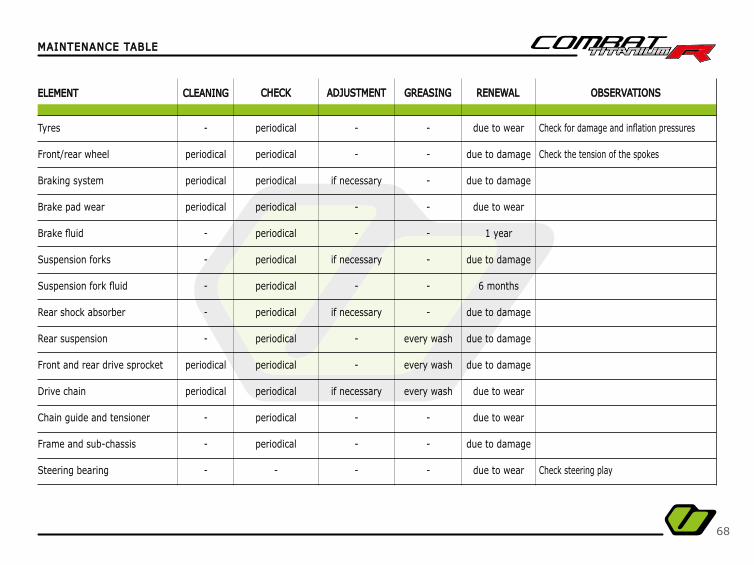
MAINTENANCE TABLEMAINTENANCE TABLE
ELEMENTELEMENT CLEANINGCLEANING CHECKCHECK ADJUSTMENTADJUSTMENT GREASINGGREASING RENEWALRENEWAL OBSERVATIONSOBSERVATIONS
Tyres
Front/rear wheel
Braking system
Brake pad wear
Brake fl uid
Suspension forks
Suspension fork fl uid
Rear shock absorber
Rear suspension
Front and rear drive sprocket
Drive chain
Chain guide and tensioner
Frame and sub-chassis
Steering bearing
Check for damage and infl ation pressures
Check the tension of the spokes
Check steering play
-
periodical
periodical
periodical
-
-
-
-
-
periodical
periodical
-
-
-
periodical
periodical
periodical
periodical
periodical
periodical
periodical
periodical
periodical
periodical
periodical
periodical
periodical
-
-
-
if necessary
-
-
if necessary
-
if necessary
-
-
if necessary
-
-
-
-
-
-
-
-
-
-
-
every wash
every wash
every wash
-
-
-
due to wear
due to damage
due to damage
due to wear
1 year
due to damage
6 months
due to damage
due to damage
due to damage
due to wear
due to wear
due to damage
due to wear
69
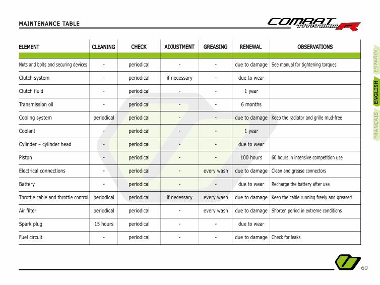
MAINTENANCE TABLEMAINTENANCE TABLE
ELEMENTELEMENT CLEANINGCLEANING CHECKCHECK ADJUSTMENTADJUSTMENT GREASINGGREASING RENEWALRENEWAL OBSERVATIONSOBSERVATIONS
Nuts and bolts and securing devices
Clutch system
Clutch fl uid
Transmission oil
Cooling system
Coolant
Cylinder – cylinder head
Piston
Electrical connections
Battery
Throttle cable and throttle control
Air fi lter
Spark plug
Fuel circuit
See manual for tightening torques
Keep the radiator and grille mud-free
60 hours in intensive competition use
Clean and grease connectors
Recharge the battery after use
Keep the cable running freely and greased
Shorten period in extreme conditions
Check for leaks
-
-
-
-
periodical
-
-
-
-
-
periodical
periodical
15 hours
-
periodical
periodical
periodical
periodical
periodical
periodical
periodical
periodical
periodical
periodical
periodical
periodical
periodical
periodical
-
if necessary
-
-
-
-
-
-
-
-
if necessary
-
-
-
-
-
-
-
-
-
-
-
every wash
-
every wash
every wash
-
-
due to damage
due to wear
1 year
6 months
due to damage
1 year
due to wear
100 hours
due to damage
due to wear
due to damage
due to damage
due to wear
due to damage
ES
PA
ÑO
LÑ
ES
PA
ÑÑÑÑO
LE
SPA
ÑÑO
LE
NG
LIS
HE
NG
LIS
HFR
AN
ÇA
ISFR
AN
ÇA
IS
70
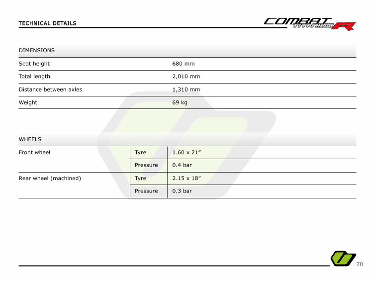
TECHNICAL DETAILSTECHNICAL DETAILS
WHEELS
DIMENSIONS
Seat height
Total length
Distance between axles
Front wheel
Rear wheel (machined)
680 mm
2,010 mm
1,310 mm
1.60 x 21”
2.15 x 18”
0.4 bar
0.3 bar
Tyre
Tyre
Pressure
Pressure
Weight 69 kg
71
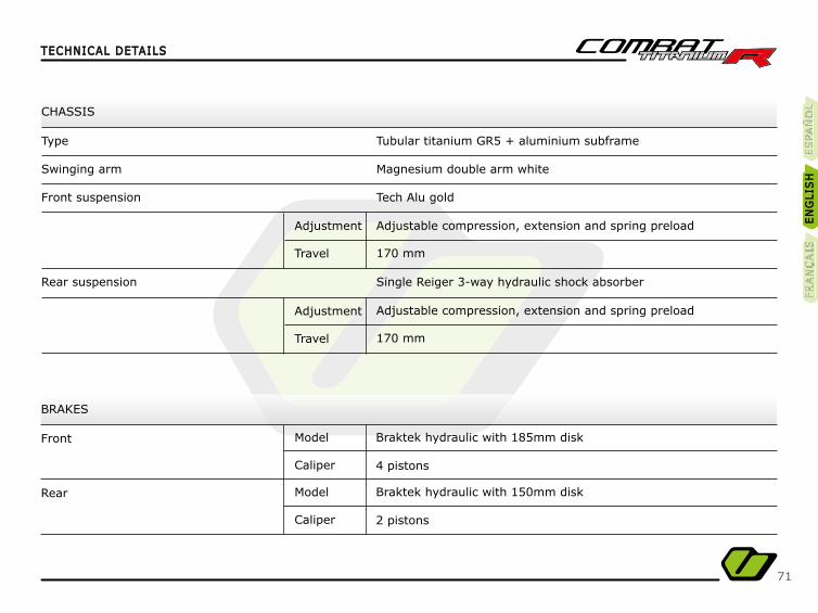
TECHNICAL DETAILSTECHNICAL DETAILS
CHASSIS
BRAKES
Type
Front
Rear
Swinging arm
Front suspension
Rear suspension
Tubular titanium GR5 + aluminium subframe
Braktek hydraulic with 185mm disk
Braktek hydraulic with 150mm disk
Magnesium double arm white
4 pistons
2 pistons
Tech Alu gold
Single Reiger 3-way hydraulic shock absorber
Adjustable compression, extension and spring preload
Adjustable compression, extension and spring preload
170 mm
Model
Model
Caliper
Caliper
170 mm
Adjustment
Adjustment
Travel
Travel
ES
PA
ÑO
LÑ
ES
PA
ÑÑÑÑO
LE
SPA
ÑÑO
LE
NG
LIS
HE
NG
LIS
HFR
AN
ÇA
ISFR
AN
ÇA
IS
72
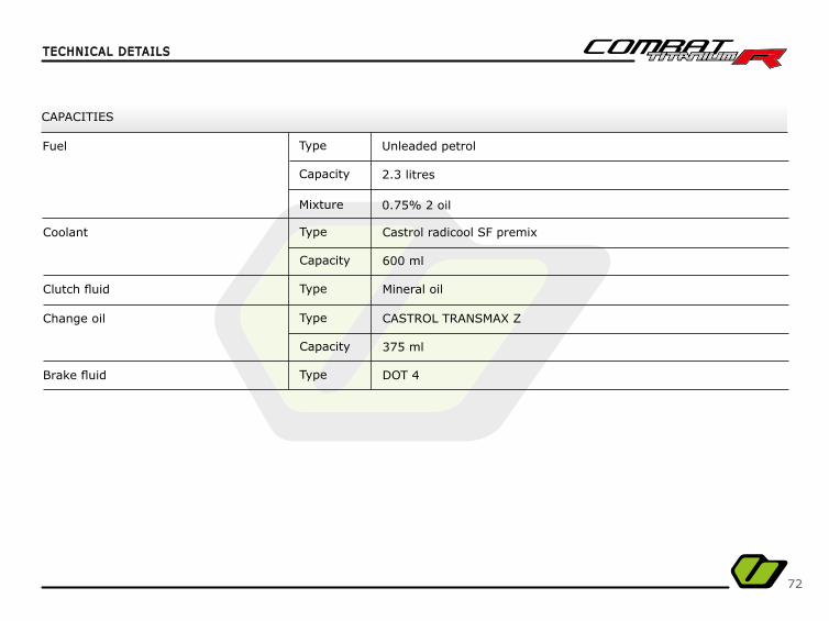
CAPACITIES
Coolant
Fuel
Clutch fl uid
Change oil
Brake fl uid
600 ml
2.3 litres
0.75% 2 oil
375 ml
Castrol radicool SF premix
Unleaded petrol
Mineral oil
CASTROL TRANSMAX Z
DOT 4
Type
Type
Type
Type
Type
Capacity
Capacity
Mixture
Capacity
TECHNICAL DETAILSTECHNICAL DETAILS
73
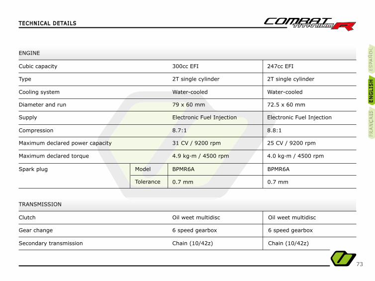
TRANSMISSION
Clutch
Gear change
Secondary transmission
Oil weet multidisc
6 speed gearbox
Chain (10/42z)
ENGINE
Cubic capacity
Type
Supply
Cooling system
Compression
Diameter and run
Maximum declared power capacity
Maximum declared torque
Spark plug
300cc EFI
2T single cylinder
Electronic Fuel Injection
Water-cooled
8.7:1
79 x 60 mm
31 CV / 9200 rpm
4.9 kg·m / 4500 rpm
BPMR6A
0.7 mm
Model
Tolerance
Oil weet multidisc
6 speed gearbox
Chain (10/42z)
247cc EFI
2T single cylinder
Electronic Fuel Injection
Water-cooled
8.8:1
72.5 x 60 mm
25 CV / 9200 rpm
4.0 kg·m / 4500 rpm
BPMR6A
0.7 mm
TECHNICAL DETAILSTECHNICAL DETAILS
ES
PA
ÑO
LÑ
ES
PA
ÑÑÑÑO
LE
SPA
ÑÑO
LE
NG
LIS
HE
NG
LIS
HFR
AN
ÇA
ISFR
AN
ÇA
IS

74
75
Félicitation pour votre achat !Félicitation pour votre achat !
Nous voudrions vous souhaitez la bienvenue chez Vertigo Motors et partager avec vous notre expérience et passion pour le Nous voudrions vous souhaitez la bienvenue chez Vertigo Motors et partager avec vous notre expérience et passion pour le trial, le design, la technique, l’innovation et la recherche. trial, le design, la technique, l’innovation et la recherche.
Soucieux d’améliorer les motos trial pour leur faire atteindre le niveau supérieur.
Chez Vertigo, nous rêvons de créer la moto idéale pour pratiquer notre passion, sans distinctions entre les amateurs et les professionnels, une moto révolutionnaire pensée pour vous.
À partir de maintenant, vous faîtes parti de notre équipe, vous intégrant à la meilleure équipe technique,pilotes, passionnés de moteurs et des meilleurs professionnels de chaque spécialité.
Tous réunis par un dénominateur commun: Passion et Expérience.Passion et Expérience.
En plus, chez Vertigo, nous vous offrons la possibilité de pratiquer le trial sur un terrain privé (Noassar)(Noassar),située à Camprodón dans le complexe hôtelier du Puig-Francó et dans lequel vous pouvez profi ter
de votre passion pour le trial. Pour plus d’information, visiter la page web: www.puigfranco.eswww.puigfranco.es
Avec ce manuel, nous vous fournissons les données, les travaux d’entretien et les réglages basiques que vous pourrez réa-liser vous-même sur votre nouvelle Vertigo. Également, chez votre Concessionnaire Offi ciel Vertigo Motors, vous trouverez une équipe d’experts qui pourra vous conseiller dans tous les domaines en rapport avec votre moto ou ses compléments.
Nous vous invitons à faire partie de notre histoire et de notre succès.
Vertigo Motors se réserve les droits d’effectuer des changements et/ou modifi cations sur ses modèles sans avis préalable.
ES
PA
ÑO
LÑ
ES
PA
ÑÑÑÑO
LE
SPA
ÑÑO
LE
NG
LIS
HE
NG
LIS
HFR
AN
ÇA
ISFR
AN
ÇA
IS

76
77
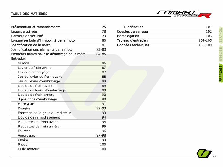
TABLE DES MATIÈRESTABLE DES MATIÈRES
Présentation et remerciementsPrésentation et remerciementsLégende utiliséeLégende utiliséeConseils de sécuritéConseils de sécuritéLongue période d’immobilité de la motoLongue période d’immobilité de la motoIdentifi cation de la motoIdentifi cation de la motoIdentifi cation des elements de la motoIdentifi cation des elements de la motoElements basics pour le démarrage de la motoElements basics pour le démarrage de la motoEntretienEntretien
GuidonLevier de frein avantLevier d’embrayageJeu du levier de frein avantJeu du levier d’embrayageLiquide de frein avantLiquide de levier d’embrayageLiquide de frein arrière3 positions d’embrayageFiltre à airBougiesEntretien de la grille du radiateurLiquide de refroidissementPlaquettes de frein avantPlaquettes de frein arrièreFourcheAmortisseurChaînePneusHuile moteur
7578798081
82-8384-85
86878788888989909091
92-939394949596
97-9899
100100
101102103
104-105106-109
Lubrifi cationCouples de serrageCouples de serrageHomologationHomologationTableau d’entretienTableau d’entretienDonnées techniquesDonnées techniques
ES
PA
ÑO
LÑ
ES
PA
ÑÑÑÑO
LE
SPA
ÑÑO
LE
NG
LIS
HE
NG
LIS
HFR
AN
ÇA
ISFR
AN
ÇA
IS
78
CONSEIL
Avec ce symbole, nous vous donnons des indications afi n de vous faciliter les opérations d’entretien que vous voulez réaliser.
AVERTISSEMENT
Avec ce symbole, nous voulons vous avertir des possibles situations de danger qui pourrait se pré-senter lors de certaines opérations décrites dans ce manuel.
Pour chaque opération d’entretien que vous réalisez, en plus des conseils et avertissements qui vous sont indiqués, veuillez toujours utiliser le sens commun pour ne pas mettre en danger votre intégrité physique ou celle des personnes qui vous aideront.
LÉGENDELÉGENDE
79
Avant d’utiliser cette moto, familiarisez-vous avec elle, situez et identifi ez tous les éléments basiques de conduite.
Lisez attentivement tous et chacun des points de ce manuel.
Cette moto a été créée pour un usage trial uniquement et ne peut donc pas supporter un second passager.
Réalisez les opérations d’entretien décrites dans ce manuel et seulement au moment indiqué pour que votre moto reste en bon état et cela le plus longtemps possible.
Utilisez un équipement adapté pour la pratique du Trial qui garantit votre sécurité (casque, vêtements adaptés, protections, etc…).
Utilisez la moto de façon progressive jusqu’à atteindre son rendement maximum.
Évitez de démarrer la moto avec la béquille abaissée.
CONSEILS DE SÉCURITÉCONSEILS DE SÉCURITÉ
ES
PA
ÑO
LÑ
ES
PA
ÑÑÑÑO
LE
SPA
ÑÑO
LE
NG
LIS
HE
NG
LIS
HFR
AN
ÇA
ISFR
AN
ÇA
IS
80
Il est nécessaire d’adopter certaines mesures pour garantir le bon entretien de la moto en cas de longue période d’immobilité du véhicule:
- Procéder à un nettoyage complet de la moto avant son démarrage.
- Réduire la pression des pneus.
- Couvrir la moto avec une housse afi n d’éviter la poussière et la saleté.
LONGUE PÉRIODE D’IMMOBILITÉ DE LA MOTOLONGUE PÉRIODE D’IMMOBILITÉ DE LA MOTO
81
IDENTIFICATION DE LA MOTOIDENTIFICATION DE LA MOTO
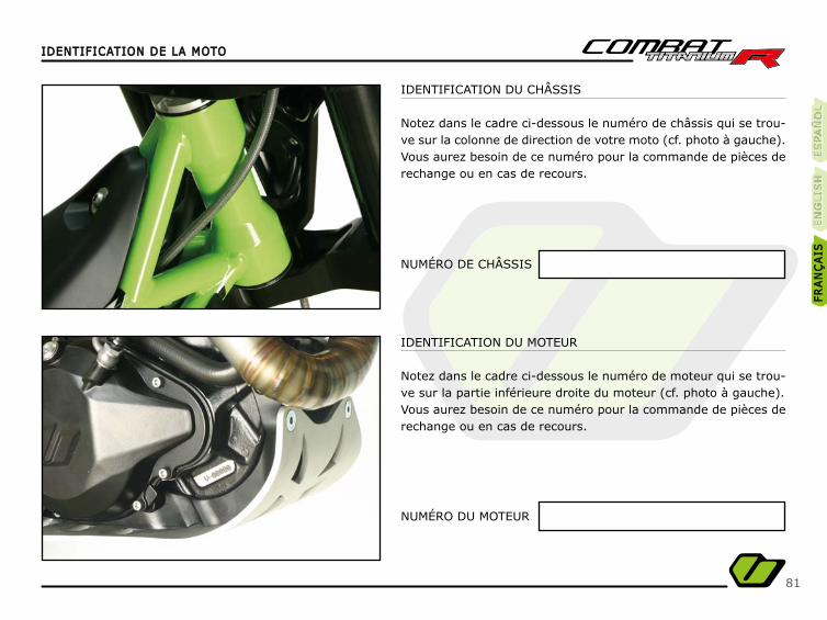
IDENTIFICATION DU CHÂSSIS
Notez dans le cadre ci-dessous le numéro de châssis qui se trou-ve sur la colonne de direction de votre moto (cf. photo à gauche).Vous aurez besoin de ce numéro pour la commande de pièces de rechange ou en cas de recours.
NUMÉRO DE CHÂSSIS
NUMÉRO DU MOTEUR
IDENTIFICATION DU MOTEUR
Notez dans le cadre ci-dessous le numéro de moteur qui se trou-ve sur la partie inférieure droite du moteur (cf. photo à gauche).Vous aurez besoin de ce numéro pour la commande de pièces de rechange ou en cas de recours.
ES
PA
ÑO
LÑ
ES
PA
ÑÑÑÑO
LE
SPA
ÑÑO
LE
NG
LIS
HE
NG
LIS
HFR
AN
ÇA
ISFR
AN
ÇA
IS

82
IDENTIFICATION DES ÉLÉMENTS DE LA MOTOIDENTIFICATION DES ÉLÉMENTS DE LA MOTO
Pot d’échappement
Bouton arrêt
Bouchon du radiateur
Levier de kick
Pédale de frein arrière
Disque de frein arrière
1 3 52 4 6
RIGHT-HAND SIDE VIEW
Identify the following elements on your motorbike in order to familiarise yourself with it before starting up.
56 4
1
3
2
83
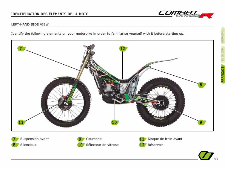
IDENTIFICATION DES ÉLÉMENTS DE LA MOTOIDENTIFICATION DES ÉLÉMENTS DE LA MOTO
Suspension avant
Silencieux
Couronne
Sélecteur de vitesse
Disque de frein avant
Réservoir
7 9 11118 12121010
LEFT-HAND SIDE VIEW
Identify the following elements on your motorbike in order to familiarise yourself with it before starting up.
ES
PA
ÑO
LÑ
ES
PA
ÑÑÑÑO
LE
SPA
ÑÑO
LE
NG
LIS
HE
NG
LIS
HFR
AN
ÇA
ISFR
AN
ÇA
IS
7 1212
1111 1010 9
8
84
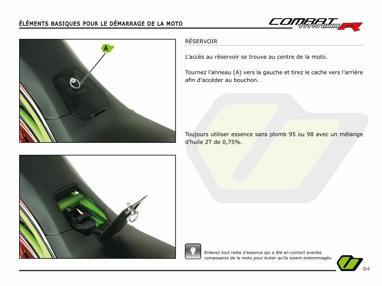
RÉSERVOIR
L’accès au réservoir se trouve au centre de la moto.
Tournez l’anneau (A) vers la gauche et tirez le cache vers l’arrière afi n d’accéder au bouchon.
Toujours utiliser essence sans plomb 95 ou 98 avec un mélange d’huile 2T de 0,75%.
Enlevez tout reste d’essence qui a été en contact aveclescomposants de la moto pour éviter qu’ils soient endommagés.
ÉLÉMENTS BASIQUES POUR LE DÉMARRAGE DE LA MOTOÉLÉMENTS BASIQUES POUR LE DÉMARRAGE DE LA MOTO
A
85
ÉLÉMENTS BASIQUES POUR LE DÉMARRAGE DE LA MOTOÉLÉMENTS BASIQUES POUR LE DÉMARRAGE DE LA MOTO
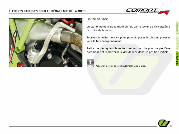
LEVIER DE KICK
Le stationnement de la moto se fait par le levier de kick située à la droite de la moto.
Tournez le levier de kick pour pouvoir poser le pied et pousser vers le bas énergiquement.
Retirez le pied quand le moteur est en marche pour ne pas l’en-dommager et remettez le levier de kick dans sa position initiale.
Actionner le levier de kick SEULEMENT avec le pied.
ES
PA
ÑO
LÑ
ES
PA
ÑÑÑÑO
LE
SPA
ÑÑO
LE
NG
LIS
HE
NG
LIS
HFR
AN
ÇA
ISFR
AN
ÇA
IS
86
ENTRETIENENTRETIEN
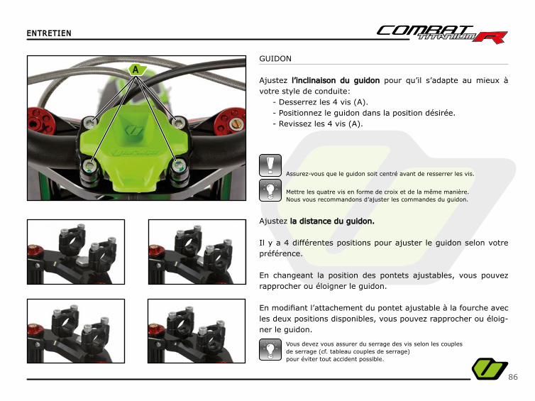
Ajustez la distance du guidon.la distance du guidon.
Il y a 4 différentes positions pour ajuster le guidon selon votre préférence.
En changeant la position des pontets ajustables, vous pouvez rapprocher ou éloigner le guidon.
En modifi ant l’attachement du pontet ajustable à la fourche avec les deux positions disponibles, vous pouvez rapprocher ou éloig-ner le guidon.
GUIDON
Ajustez l’inclinaison du guidonl’inclinaison du guidon pour qu’il s’adapte au mieux à votre style de conduite:
- Desserrez les 4 vis (A).- Positionnez le guidon dans la position désirée.- Revissez les 4 vis (A).
Mettre les quatre vis en forme de croix et de la même manière.Nous vous recommandons d’ajuster les commandes du guidon.
Vous devez vous assurer du serrage des vis selon les couplesde serrage (cf. tableau couples de serrage)pour éviter tout accident possible.
Assurez-vous que le guidon soit centré avant de resserrer les vis.
A
87
ENTRETIENENTRETIEN
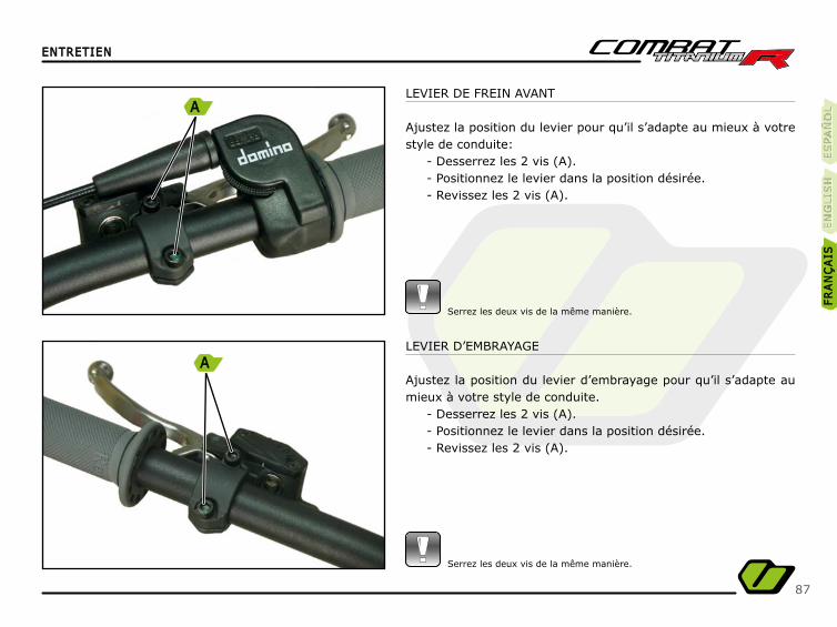
LEVIER DE FREIN AVANT
Ajustez la position du levier pour qu’il s’adapte au mieux à votre style de conduite:
- Desserrez les 2 vis (A).- Positionnez le levier dans la position désirée.- Revissez les 2 vis (A).
Serrez les deux vis de la même manière.
LEVIER D’EMBRAYAGE
Ajustez la position du levier d’embrayage pour qu’il s’adapte au mieux à votre style de conduite.
- Desserrez les 2 vis (A).- Positionnez le levier dans la position désirée.- Revissez les 2 vis (A).
Serrez les deux vis de la même manière.
ES
PA
ÑO
LÑ
ES
PA
ÑÑÑÑO
LE
SPA
ÑÑO
LE
NG
LIS
HE
NG
LIS
HFR
AN
ÇA
ISFR
AN
ÇA
IS
A
A
88
ENTRETIENENTRETIEN
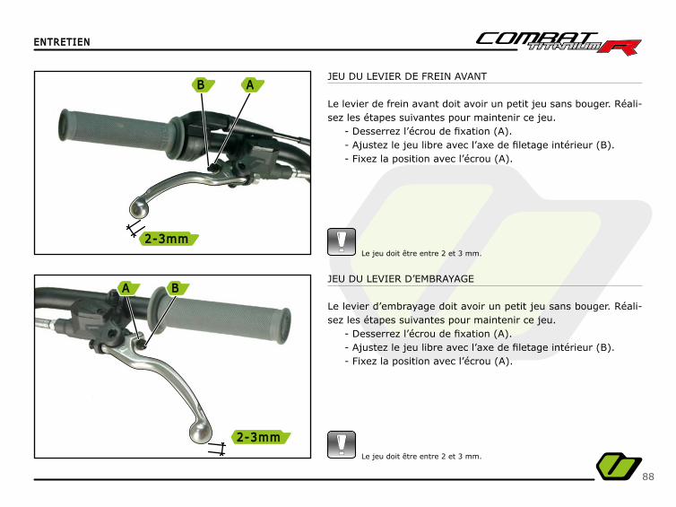
JEU DU LEVIER DE FREIN AVANT
Le levier de frein avant doit avoir un petit jeu sans bouger. Réali-sez les étapes suivantes pour maintenir ce jeu.
- Desserrez l’écrou de fi xation (A).- Ajustez le jeu libre avec l’axe de fi letage intérieur (B).- Fixez la position avec l’écrou (A).
Le jeu doit être entre 2 et 3 mm.
JEU DU LEVIER D’EMBRAYAGE
Le levier d’embrayage doit avoir un petit jeu sans bouger. Réali-sez les étapes suivantes pour maintenir ce jeu.
- Desserrez l’écrou de fi xation (A).- Ajustez le jeu libre avec l’axe de fi letage intérieur (B).- Fixez la position avec l’écrou (A).
Le jeu doit être entre 2 et 3 mm.
B
2-3mm2-3mm
A
A
2-3mm2-3mm
B
89
ENTRETIENENTRETIEN
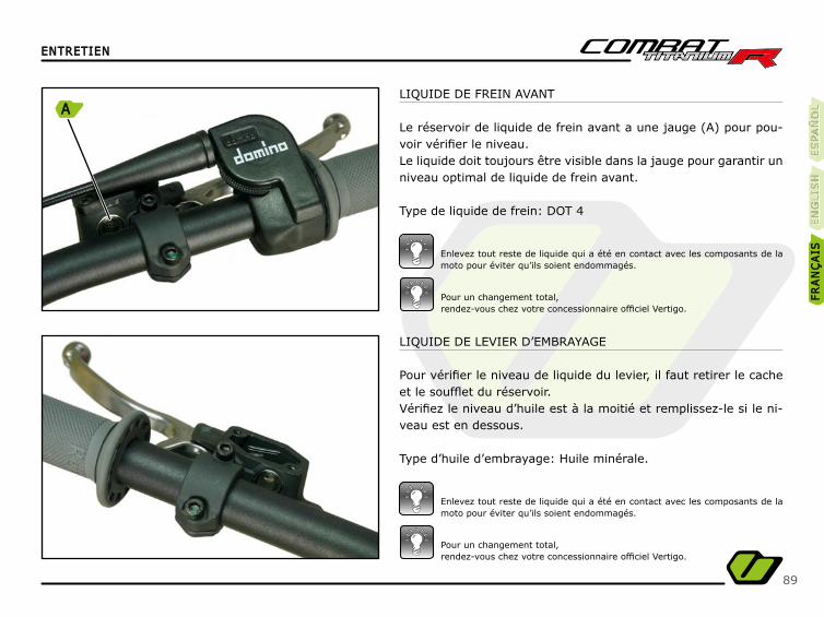
LIQUIDE DE LEVIER D’EMBRAYAGE
Pour vérifi er le niveau de liquide du levier, il faut retirer le cache et le souffl et du réservoir.Vérifi ez le niveau d’huile est à la moitié et remplissez-le si le ni-veau est en dessous.
Type d’huile d’embrayage: Huile minérale.
LIQUIDE DE FREIN AVANT
Le réservoir de liquide de frein avant a une jauge (A) pour pou-voir vérifi er le niveau.Le liquide doit toujours être visible dans la jauge pour garantir un niveau optimal de liquide de frein avant.
Type de liquide de frein: DOT 4
Pour un changement total,rendez-vous chez votre concessionnaire offi ciel Vertigo.
Pour un changement total,rendez-vous chez votre concessionnaire offi ciel Vertigo.
Enlevez tout reste de liquide qui a été en contact avec les composants de la moto pour éviter qu’ils soient endommagés.
Enlevez tout reste de liquide qui a été en contact avec les composants de la moto pour éviter qu’ils soient endommagés.
ES
PA
ÑO
LÑ
ES
PA
ÑÑÑÑO
LE
SPA
ÑÑO
LE
NG
LIS
HE
NG
LIS
HFR
AN
ÇA
ISFR
AN
ÇA
IS
A
90
ENTRETIENENTRETIEN
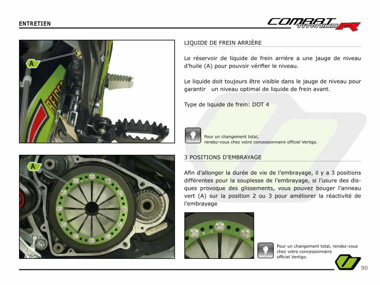
LIQUIDE DE FREIN ARRIÈRE
Le réservoir de liquide de frein arrière a une jauge de niveau d’huile (A) pour pouvoir vérifi er le niveau.
Le liquide doit toujours être visible dans le jauge de niveau pour garantir un niveau optimal de liquide de frein avant.
Type de liquide de frein: DOT 4
Pour un changement total,rendez-vous chez votre concessionnaire offi ciel Vertigo.
3 POSITIONS D’EMBRAYAGE
Afi n d’allonger la durée de vie de l’embrayage, il y a 3 positions différentes pour la souplesse de l’embrayage, si l’usure des dis-ques provoque des glissements, vous pouvez bouger l’anneau vert (A) sur la position 2 ou 3 pour améliorer la réactivité de l’embrayage
Pour un changement total, rendez-vous chez votre concessionnaireoffi ciel Vertigo.
A
A
91
ENTRETIENENTRETIEN
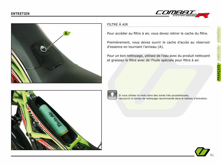
FILTRE À AIR
Pour accéder au fi ltre à air, vous devez retirer le cache du fi ltre.
Premièrement, vous devez ouvrir le cache d’accès au réservoir d’essence en tournant l’anneau (A).
Pour un bon nettoyage, utilisez de l’eau avec du produit nettoyant et graissez le fi ltre avec de l’huile spéciale pour fi ltre à air.
Si vous utilisez la moto dans des zones très poussiéreuses,raccourcir le temps de nettoyage recommandé dans le tableau d’entretien.
ES
PA
ÑO
LÑ
ES
PA
ÑÑÑÑO
LE
SPA
ÑÑO
LE
NG
LIS
HE
NG
LIS
HFR
AN
ÇA
ISFR
AN
ÇA
IS
A
92
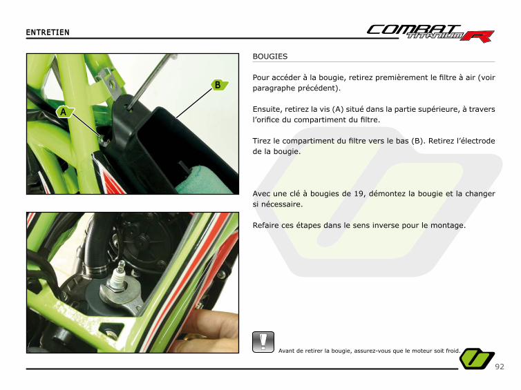
BOUGIES
Pour accéder à la bougie, retirez premièrement le fi ltre à air (voir paragraphe précédent).
Ensuite, retirez la vis (A) situé dans la partie supérieure, à travers l’orifi ce du compartiment du fi ltre. Tirez le compartiment du fi ltre vers le bas (B). Retirez l’électrode de la bougie.
Avec une clé à bougies de 19, démontez la bougie et la changer si nécessaire.
Refaire ces étapes dans le sens inverse pour le montage.
ENTRETIENENTRETIEN
Avant de retirer la bougie, assurez-vous que le moteur soit froid.
B
A
93
ENTRETIENENTRETIEN
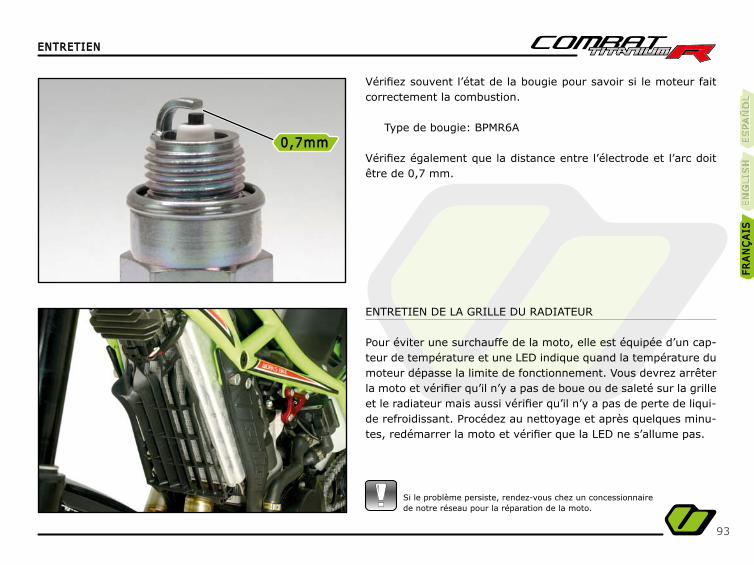
ENTRETIEN DE LA GRILLE DU RADIATEUR
Pour éviter une surchauffe de la moto, elle est équipée d’un cap-teur de température et une LED indique quand la température du moteur dépasse la limite de fonctionnement. Vous devrez arrêter la moto et vérifi er qu’il n’y a pas de boue ou de saleté sur la grille et le radiateur mais aussi vérifi er qu’il n’y a pas de perte de liqui-de refroidissant. Procédez au nettoyage et après quelques minu-tes, redémarrer la moto et vérifi er que la LED ne s’allume pas.
Vérifi ez souvent l’état de la bougie pour savoir si le moteur fait correctement la combustion.
Type de bougie: BPMR6A
Vérifi ez également que la distance entre l’électrode et l’arc doit être de 0,7 mm.
Si le problème persiste, rendez-vous chez un concessionnairede notre réseau pour la réparation de la moto.
ES
PA
ÑO
LÑ
ES
PA
ÑÑÑÑO
LE
SPA
ÑÑO
LE
NG
LIS
HE
NG
LIS
HFR
AN
ÇA
ISFR
AN
ÇA
IS
0,7mm0,7mm
94
ENTRETIENENTRETIEN
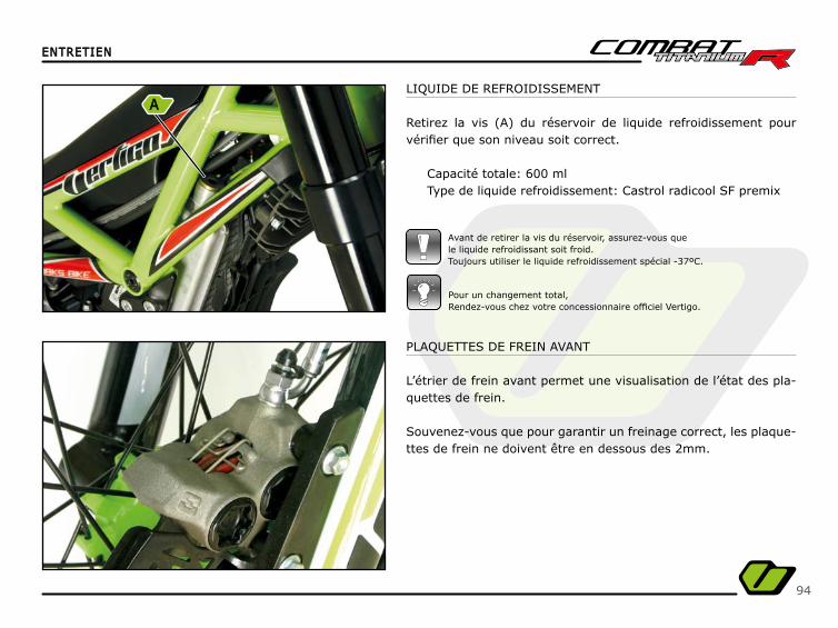
LIQUIDE DE REFROIDISSEMENT
Retirez la vis (A) du réservoir de liquide refroidissement pour vérifi er que son niveau soit correct.
Capacité totale: 600 mlType de liquide refroidissement: Castrol radicool SF premix
Avant de retirer la vis du réservoir, assurez-vous quele liquide refroidissant soit froid.Toujours utiliser le liquide refroidissement spécial -37ºC.
Pour un changement total,Rendez-vous chez votre concessionnaire offi ciel Vertigo.
PLAQUETTES DE FREIN AVANT
L’étrier de frein avant permet une visualisation de l’état des pla-quettes de frein.
Souvenez-vous que pour garantir un freinage correct, les plaque-ttes de frein ne doivent être en dessous des 2mm.
A
95
ENTRETIENENTRETIEN
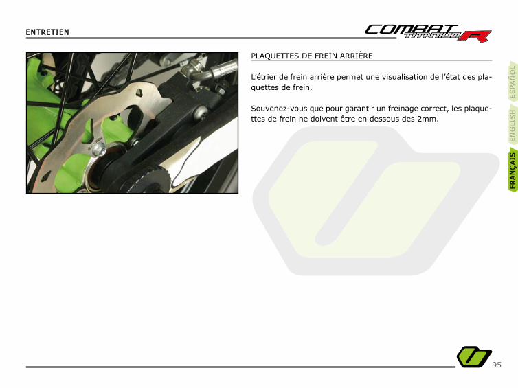
PLAQUETTES DE FREIN ARRIÈRE
L’étrier de frein arrière permet une visualisation de l’état des pla-quettes de frein.
Souvenez-vous que pour garantir un freinage correct, les plaque-ttes de frein ne doivent être en dessous des 2mm.
ES
PA
ÑO
LÑ
ES
PA
ÑÑÑÑO
LE
SPA
ÑÑO
LE
NG
LIS
HE
NG
LIS
HFR
AN
ÇA
ISFR
AN
ÇA
IS
96
ENTRETIENENTRETIEN
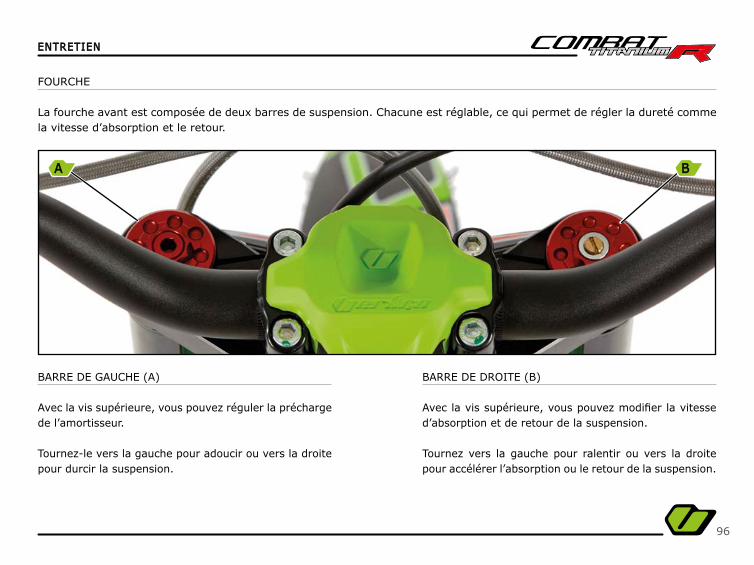
BARRE DE GAUCHE (A)
Avec la vis supérieure, vous pouvez réguler la précharge de l’amortisseur.
Tournez-le vers la gauche pour adoucir ou vers la droite pour durcir la suspension.
BARRE DE DROITE (B)
Avec la vis supérieure, vous pouvez modifi er la vitesse d’absorption et de retour de la suspension.
Tournez vers la gauche pour ralentir ou vers la droite pour accélérer l’absorption ou le retour de la suspension.
FOURCHE
La fourche avant est composée de deux barres de suspension. Chacune est réglable, ce qui permet de régler la dureté comme la vitesse d’absorption et le retour.
A B

97
ENTRETIENENTRETIEN
L’amortisseur est réglé pour un poids de 70 à 80 kg.
AMORTISSEUR
L’amortisseur arrière a trois réglages différents.
- Réglage de la précharge Réglage de la précharge du ressort de l’amortisseur (A).
L’amortisseur est composé de deux écrous qui permet-tent de modifi er la précharge du ressort de l’amortisseur. Un pour choisir la position et l’autre pour la maintenir.
- Réglage de la compressionRéglage de la compression.
L’écrou de réglage se situe sur la partie inférieure avant du bras.
Le bouton violet (B) sur l’amortisseur est le réglage de la com-pression. Tourner dans le sens horaire pour plus d’amortissement en compression ou antihoraire pour moins l’amortissement en compression.
Le nombre maximal de clics sur ce réglage est 24.
ES
PA
ÑO
LÑ
ES
PA
ÑÑÑÑO
LE
SPA
ÑÑO
LE
NG
LIS
HE
NG
LIS
HFR
AN
ÇA
ISFR
AN
ÇA
IS
A
B

98
ENTRETIENENTRETIEN
- Réglage du rebond (C)Réglage du rebond (C)
Le réglage du rebond possède 50 crans et se trouve sur la partie supérieure de l’amortisseur et est réglable grâce à un tournevis plat. En tournant l’écrou de réglage dans le sens des aiguilles, vous gagnerez en stabilité mais perdrez en traction. Si vous vou-lez gagner en traction, vous devrez tourner l’écrou dans le sens inverse des aiguilles.
Manipulez les écrous de réglage avec délicatesse, si vous dépassez la limite de réglage, cela peut endommager l’amortisseur.Toujours prendre note du nombre de cran passé, si vous modifi ez les réglages afi n de pouvoir retrouver le réglage standard, si nécessaire.
C
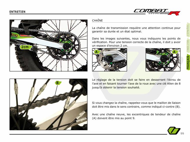
99
ENTRETIENENTRETIEN
CHAÎNE
La chaîne de transmission requière une attention continue pour garantir sa durée et un état optimal. Dans les images suivantes, nous vous indiquons les points de vérifi cation. Pour une tension correcte de la chaîne, il doit y avoir un espace d’environ 2 cm.
Le réglage de la tension doit se faire en desserrant l’écrou de l’axe et en faisant tourner l’axe de la roue avec une clé Allen de 8 jusqu’à obtenir la tension souhaité.
Si vous changez la chaîne, rappelez-vous que le maillon de liaison doit être mis dans le sens contraire, comme indiqué ci-contre (B).
Avec une chaîne neuve, les excentriques de tendeur de chaîne (A) doivent être mis au point 9.
ES
PA
ÑO
LÑ
ES
PA
ÑÑÑÑO
LE
SPA
ÑÑO
LE
NG
LIS
HE
NG
LIS
HFR
AN
ÇA
ISFR
AN
ÇA
IS
B
2cm2cmA A
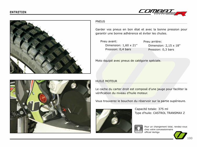
100
ENTRETIENENTRETIEN
PNEUS
Garder vos pneus en bon état et avec la bonne pression pour garantir une bonne adhérence et éviter les chutes.
Pneu avant:Dimension: 1,60 x 21”Pression: 0,4 bars
HUILE MOTEUR
Le cache du carter droit est composé d’une jauge pour faciliter la vérifi cation du niveau d’huile moteur.
Vous trouverez le bouchon du réservoir sur la partie supérieure.
Capacité totale: 375 mlType d’huile: CASTROL TRANSMAX Z
Pour un changement total, rendez-vous chez votre concessionnaireoffi ciel Vertigo
Moto équipé avec pneus de catégorie spéciale.
Pneu arrière:Dimension: 2,15 x 18” Pression: 0,3 bars
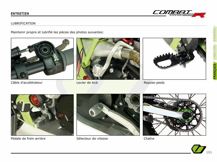
101
ENTRETIENENTRETIEN
LUBRIFICATION
Maintenir propre et lubrifi é les pièces des photos suivantes:
Câble d’accélérateur
Pédale de frein arrière
Levier de kick
Sélecteur de vitesse
Repose-pieds
Chaîne
ES
PA
ÑO
LÑ
ES
PA
ÑÑÑÑO
LE
SPA
ÑÑO
LE
NG
LIS
HE
NG
LIS
HFR
AN
ÇA
ISFR
AN
ÇA
IS
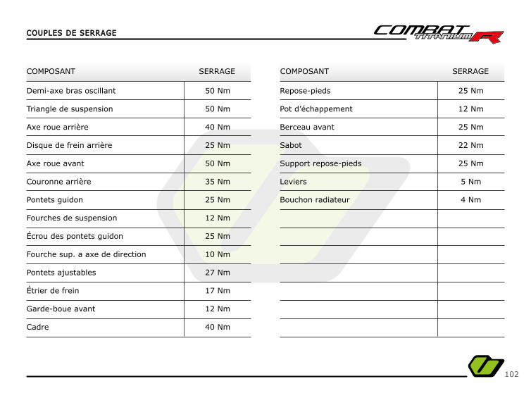
102
COUPLES DE SERRAGECOUPLES DE SERRAGE
COMPOSANT COMPOSANTSERRAGE SERRAGE
Demi-axe bras oscillant
Triangle de suspension
Axe roue arrière
Disque de frein arrière
Axe roue avant
Couronne arrière
Pontets guidon
Fourches de suspension
Écrou des pontets guidon
Fourche sup. a axe de direction
Pontets ajustables
Étrier de frein
Garde-boue avant
Cadre
Repose-pieds
Pot d’échappement
Berceau avant
Sabot
Support repose-pieds
Leviers
Bouchon radiateur
50 Nm
50 Nm
40 Nm
25 Nm
50 Nm
35 Nm
25 Nm
12 Nm
25 Nm
10 Nm
27 Nm
17 Nm
12 Nm
40 Nm
25 Nm
12 Nm
25 Nm
22 Nm
25 Nm
5 Nm
4 Nm
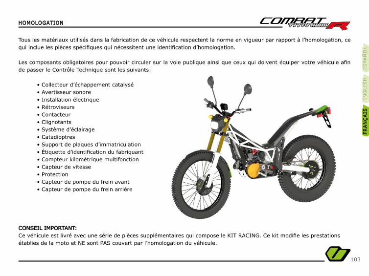
103
HOMOLOGATIONHOMOLOGATION
Tous les matériaux utilisés dans la fabrication de ce véhicule respectent la norme en vigueur par rapport à l’homologation, ce qui inclue les pièces spécifi ques qui nécessitent une identifi cation d’homologation.
Les composants obligatoires pour pouvoir circuler sur la voie publique ainsi que ceux qui doivent équiper votre véhicule afi n de passer le Contrôle Technique sont les suivants:
• Collecteur d’échappement catalysé• Avertisseur sonore• Installation électrique• Rétroviseurs• Contacteur• Clignotants• Système d’éclairage• Catadioptres• Support de plaques d’immatriculation• Étiquette d’identifi cation du fabriquant• Compteur kilométrique multifonction• Capteur de vitesse• Protection • Capteur de pompe du frein avant• Capteur de pompe du frein arrière
CONSEIL IMPORTANT:CONSEIL IMPORTANT:Ce véhicule est livré avec une série de pièces supplémentaires qui compose le KIT RACING. Ce kit modifi e les prestationsétablies de la moto et NE sont PAS couvert par l’homologation du véhicule.
ES
PA
ÑO
LÑ
ES
PA
ÑÑÑÑO
LE
SPA
ÑÑÑO
LE
NG
LIS
HE
NG
LIS
HFR
AN
ÇA
ISFR
AN
ÇA
IS
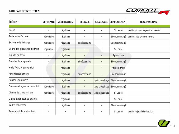
104
TABLEAU D’ENTRETIENTABLEAU D’ENTRETIEN
ÉLÉMENTÉLÉMENT NETTOYAGENETTOYAGE VÉRIFICATIONVÉRIFICATION RÉGLAGERÉGLAGE GRAISSAGEGRAISSAGE REMPLACEMENTREMPLACEMENT OBSERVATIONSOBSERVATIONS
Pneus
Jante avant/arrière
Système de freinage
Usure des plaquettes de frein
Liquide de frein
Fourche de suspension
Huile fourche suspension
Amortisseur arrière
Suspension arrière
Couronne et pignon de transmission
Chaîne de transmission
Guide et tendeur de chaîne
Cadre et berceau
Roulement de la direction
Vérifi er les dommages et la pression
Vérifi er la tension des rayons
Vérifi er le jeu de la direction
-
réguliaire
réguliaire
réguliaire
-
-
-
-
-
réguliaire
réguliaire
-
-
-
réguliaire
réguliaire
réguliaire
réguliaire
réguliaire
réguliaire
réguliaire
réguliaire
réguliaire
réguliaire
réguliaire
réguliaire
réguliaire
-
-
-
si nécessaire
-
-
si nécessaire
-
si nécessaire
-
-
si nécessaire
-
-
-
-
-
-
-
-
-
-
-
Après chaque lavage
Après chaque lavage
Après chaque lavage
-
-
-
Si usure
Si endommagé
Si endommagé
Si usure
Après 1 an
Si endommagé
Après 6 mois
Si endommagé
Si endommagé
Si endommagé
Si usure
Si usure
Si endommagé
Si usure
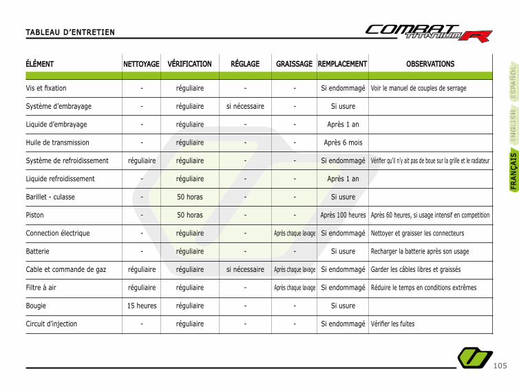
105
TABLEAU D’ENTRETIENTABLEAU D’ENTRETIEN
ÉLÉMENTÉLÉMENT NETTOYAGENETTOYAGE VÉRIFICATIONVÉRIFICATION RÉGLAGERÉGLAGE GRAISSAGEGRAISSAGE REMPLACEMENTREMPLACEMENT OBSERVATIONSOBSERVATIONS
Vis et fi xation
Système d’embrayage
Liquide d’embrayage
Huile de transmission
Système de refroidissement
Liquide refroidissement
Barillet - culasse
Piston
Connection électrique
Batterie
Cable et commande de gaz
Filtre à air
Bougie
Circuit d’injection
Voir le manuel de couples de serrage
Vérifi er qu’il n’y ait pas de boue sur la grille et le radiateur
Après 60 heures, si usage intensif en competition
Nettoyer et graisser les connecteurs
Recharger la batterie après son usage
Garder les câbles libres et graissés
Réduire le temps en conditions extrêmes
Vérifi er les fuites
-
-
-
-
réguliaire
-
-
-
-
-
réguliaire
réguliaire
15 heures
-
réguliaire
réguliaire
réguliaire
réguliaire
réguliaire
réguliaire
50 horas
50 horas
réguliaire
réguliaire
réguliaire
réguliaire
réguliaire
réguliaire
-
si nécessaire
-
-
-
-
-
-
-
-
si nécessaire
-
-
-
-
-
-
-
-
-
-
-
Après chaque lavage
-
Après chaque lavage
Après chaque lavage
-
-
Si endommagé
Si usure
Après 1 an
Après 6 mois
Si endommagé
Après 1 an
Si usure
Après 100 heures
Si endommagé
Si usure
Si endommagé
Si endommagé
Si usure
Si endommagé
ES
PA
ÑO
LÑ
ES
PA
ÑÑÑÑO
LE
SPA
ÑÑO
LE
NG
LIS
HE
NG
LIS
HFR
AN
ÇA
ISFR
AN
ÇA
IS

106
DONNÉES TECHNIQUESDONNÉES TECHNIQUES
ROUES
DIMENSIONS
Hauteur siège
Longitude totale
Distance entre les axes
Roue avant
Roue arrière (mécanisé)
680 mm
2.010 mm
1.310 mm
1,60 x 21”
2,15 x 18”
0,4 bars
0,3 bars
Pneu
Pneu
Pression
Pression
Poids 69 kg
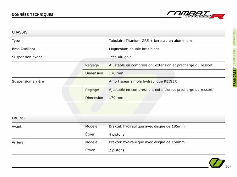
107
DONNÉES TECHNIQUESDONNÉES TECHNIQUES
CHASSIS
FREINS
Type
Avant
Arrière
Bras Oscillant
Suspension avant
Suspension arrière
Tubulaire Titanium GR5 + berceau en aluminium
Braktek hydiraulique avec disque de 185mm
Braktek hydiraulique avec disque de 150mm
Magnesium double bras blanc
4 pistons
2 pistons
Tech Alu gold
Amortisseur simple hydraulique REIGER
Ajustable en compression, extension et précharge du ressort
Ajustable en compression, extension et précharge du ressort
170 mm
170 mm
Modèle
Modèle
Étrier
Étrier
Réglage
Réglage
Dimension
Dimension
ES
PA
ÑO
LÑ
ES
PA
ÑÑÑÑO
LE
SPA
ÑÑO
LE
NG
LIS
HE
NG
LIS
HFR
AN
ÇA
ISFR
AN
ÇA
IS
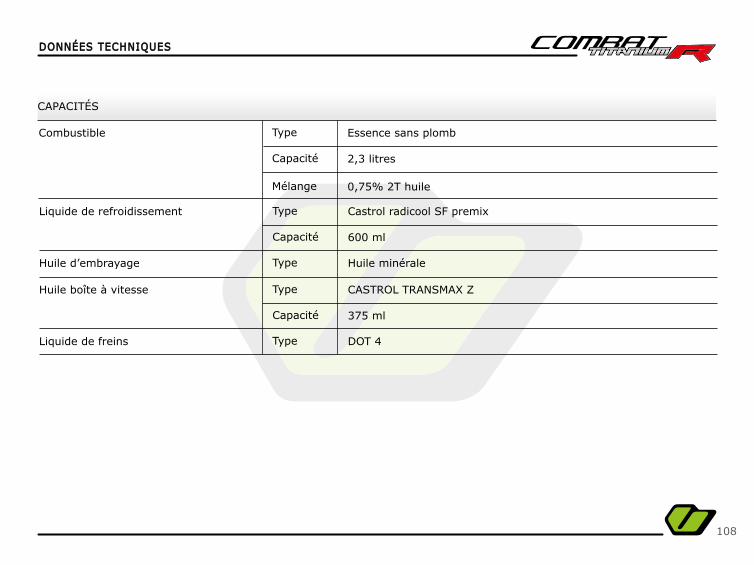
108
DONNÉES TECHNIQUESDONNÉES TECHNIQUES
CAPACITÉS
Liquide de refroidissement
Combustible
Huile d’embrayage
Huile boîte à vitesse
Liquide de freins
600 ml
2,3 litres
0,75% 2T huile
375 ml
Castrol radicool SF premix
Essence sans plomb
Huile minérale
CASTROL TRANSMAX Z
DOT 4
Type
Type
Type
Type
Type
Capacité
Capacité
Mélange
Capacité
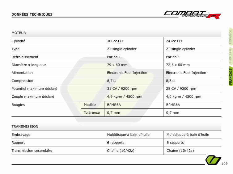
109
DONNÉES TECHNIQUESDONNÉES TECHNIQUES
TRANSMISSION
Embrayage
Rapport
Transmission secondaire
Multidisque à bain d’huile
6 rapports
Chaîne (10/42z)
MOTEUR
Cylindré
Type
Alimentation
Refroidissement
Compression
Diamètre x longueur
Potentiel maximum déclaré
Couple maximum déclaré
Bougies
300cc EFI
2T single cylinder
Electronic Fuel Injection
Par eau
8,7:1
79 x 60 mm
31 CV / 9200 rpm
4,9 kg·m / 4500 rpm
BPMR6A
0,7 mm
Modèle
Tolérence
Multidisque à bain d’huile
6 rapports
Chaîne (10/42z)
247cc EFI
2T single cylinder
Electronic Fuel Injection
Par eau
8,8:1
72,5 x 60 mm
25 CV / 9200 rpm
4,0 kg·m / 4500 rpm
BPMR6A
0,7 mm
ES
PA
ÑO
LÑ
ES
PA
ÑÑÑÑO
LE
SPA
ÑÑO
LE
NG
LIS
HE
NG
LIS
HFR
AN
ÇA
ISFR
AN
ÇA
IS

CONTACT US
GENERAL INFORMATION
info@ver gomotors.com
(+34) + 34 931 701 655
ww
w.c
iand
isse
ny.c
omw
ww
.cia
ndis
seny
.com