
EEPROM Image Creation Tool (EICT) User Guide - Intel Intel Atom Inside, Intel Core, Intel Inside,...
16
Document Number: 470337-1.0 EEPROM Image Creation Tool (EICT) for Intel ® Communications Chipset 89xx Series User Guide October 2012 Intel Confidential
Transcript of EEPROM Image Creation Tool (EICT) User Guide - Intel Intel Atom Inside, Intel Core, Intel Inside,...

Document Number: 470337-1.0
EEPROM Image Creation Tool (EICT) for Intel® Communications Chipset 89xx SeriesUser Guide
October 2012
Intel Confidential
Review Manager ([email protected])
New Stamp

EEPROM Image Creation Tool (EICT) for Intel® Communications Chipset 89xx SeriesUser Guide October 20122 Intel Confidential Document Number: 470337-1.0
Legal Lines and DisclaimersINFORMATION IN THIS DOCUMENT IS PROVIDED IN CONNECTION WITH INTEL PRODUCTS. NO LICENSE, EXPRESS OR IMPLIED, BY ESTOPPEL OR OTHERWISE, TO ANY INTELLECTUAL PROPERTY RIGHTS IS GRANTED BY THIS DOCUMENT. EXCEPT AS PROVIDED IN INTEL'S TERMS AND CONDITIONS OF SALE FOR SUCH PRODUCTS, INTEL ASSUMES NO LIABILITY WHATSOEVER AND INTEL DISCLAIMS ANY EXPRESS OR IMPLIED WARRANTY, RELATING TO SALE AND/OR USE OF INTEL PRODUCTS INCLUDING LIABILITY OR WARRANTIES RELATING TO FITNESS FOR A PARTICULAR PURPOSE, MERCHANTABILITY, OR INFRINGEMENT OF ANY PATENT, COPYRIGHT OR OTHER INTELLECTUAL PROPERTY RIGHT.A "Mission Critical Application" is any application in which failure of the Intel Product could result, directly or indirectly, in personal injury or death. SHOULD YOU PURCHASE OR USE INTEL'S PRODUCTS FOR ANY SUCH MISSION CRITICAL APPLICATION, YOU SHALL INDEMNIFY AND HOLD INTEL AND ITS SUBSIDIARIES, SUBCONTRACTORS AND AFFILIATES, AND THE DIRECTORS, OFFICERS, AND EMPLOYEES OF EACH, HARMLESS AGAINST ALL CLAIMS COSTS, DAMAGES, AND EXPENSES AND REASONABLE ATTORNEYS' FEES ARISING OUT OF, DIRECTLY OR INDIRECTLY, ANY CLAIM OF PRODUCT LIABILITY, PERSONAL INJURY, OR DEATH ARISING IN ANY WAY OUT OF SUCH MISSION CRITICAL APPLICATION, WHETHER OR NOT INTEL OR ITS SUBCONTRACTOR WAS NEGLIGENT IN THE DESIGN, MANUFACTURE, OR WARNING OF THE INTEL PRODUCT OR ANY OF ITS PARTS.Intel may make changes to specifications and product descriptions at any time, without notice. Designers must not rely on the absence or characteristics of any features or instructions marked "reserved" or "undefined". Intel reserves these for future definition and shall have no responsibility whatsoever for conflicts or incompatibilities arising from future changes to them. The information here is subject to change without notice. Do not finalize a design with this information.The products described in this document may contain design defects or errors known as errata which may cause the product to deviate from published specifications. Current characterized errata are available on request.Contact your local Intel sales office or your distributor to obtain the latest specifications and before placing your product order.Copies of documents which have an order number and are referenced in this document, or other Intel literature, may be obtained by calling 1-800-548-4725, or go to: http://www.intel.com/design/literature.htm Any software source code reprinted in this document is furnished for informational purposes only and may only be used or copied and no license, express or implied, by estoppel or otherwise, to any of the reprinted source code is granted by this document.Intel processor numbers are not a measure of performance. Processor numbers differentiate features within each processor family, not across different processor families. Go to: http://www.intel.com/products/processor%5Fnumber/Code Names are only for use by Intel to identify products, platforms, programs, services, etc. (“products”) in development by Intel that have not been made commercially available to the public, i.e., announced, launched or shipped. They are never to be used as “commercial” names for products. Also, they are not intended to function as trademarks.BlueMoon, BunnyPeople, Celeron, Celeron Inside, Centrino, Centrino Inside, Cilk, Core Inside, E-GOLD, i960, Intel, the Intel logo, Intel AppUp, Intel Atom, Intel Atom Inside, Intel Core, Intel Inside, Intel Insider, the Intel Inside logo, Intel NetBurst, Intel NetMerge, Intel NetStructure, Intel SingleDriver, Intel SpeedStep, Intel Sponsors of Tomorrow., the Intel Sponsors of Tomorrow. logo, Intel StrataFlash, Intel vPro, Intel XScale, InTru, the InTru logo, the InTru Inside logo, InTru soundmark, Itanium, Itanium Inside, MCS, MMX, Moblin, Pentium, Pentium Inside, Puma, skoool, the skoool logo, SMARTi, Sound Mark, The Creators Project, The Journey Inside, Thunderbolt, Ultrabook, vPro Inside, VTune, Xeon, Xeon Inside, X-GOLD, XMM, X-PMU and XPOSYS are trademarks of Intel Corporation in the U.S. and/or other countries.*Other names and brands may be claimed as the property of others.Copyright © 2012, Intel Corporation. All rights reserved.

EEPROM Image Creation Tool (EICT) for Intel® Communications Chipset 89xx SeriesOctober 2012 User GuideDocument Number: 470337-1.0 Intel Confidential 3
EICT
Contents
1.0 Introduction ..............................................................................................................51.1 Intended Audience ..............................................................................................5
1.1.1 Document Conventions .............................................................................51.2 Feature List ........................................................................................................61.3 EICT Package Details ...........................................................................................6
1.3.1 Where to find Current Software and Documentation......................................61.3.2 Package Naming Convention......................................................................71.3.3 Package Contents.....................................................................................7
2.0 Installing EICT ..........................................................................................................72.1 Run-Time Requirements.......................................................................................72.2 Operating System Support ...................................................................................72.3 Installing the Package..........................................................................................7
3.0 Creating an Image using EICT ...................................................................................83.1 Selecting an EEPROM Image .................................................................................83.2 Starting the EICT Interface ...................................................................................8
3.2.1 Main Window Components.........................................................................83.3 Importing an EEPROM Image .............................................................................. 103.4 Determining EEPROM Changes ............................................................................ 11
3.4.1 Configuration Pointer Files ....................................................................... 113.4.2 Configuration File Format ........................................................................ 15
3.5 Building an Image File ....................................................................................... 16
Figures1 EICT Main Window .....................................................................................................92 EEPROM Image Import Window ................................................................................. 103 EEPROM Map Offset.................................................................................................. 114 Main Window with Configuration Pointer Selected ......................................................... 145 Configuration File Window ......................................................................................... 156 Build Image Dialog Box............................................................................................. 16
Tables1 Related Documents ....................................................................................................62 EICT Directory Structure .............................................................................................7

EICT
EEPROM Image Creation Tool (EICT) for Intel® Communications Chipset 89xx SeriesUser Guide October 20124 Intel Confidential Document Number: 470337-1.0
Revision History
Date Revision Description
September 2012 1.0 Initial public release of document.

EEPROM Image Creation Tool (EICT) for Intel® Communications Chipset 89xx SeriesOctober 2012 User GuideDocument Number: 470337-1.0 Intel Confidential 5
EICT
1.0 IntroductionThe EEPROM Image Creation Tool (EICT) is used to generate an EEPROM image for use on a Intel® Communications Chipset 89xx Series target platform.
EICT may be updated throughout the various release cycles. As a general rule, ensure that the tool, configuration files, and other content are all from the same release.
Note: In this document for convenience, the terms chipset, Platform Controller Hub, and PCH are used as generic references to the Intel® Communications Chipset 89xx Series (previously codenamed Cave Creek).
The EEPROM stores information needed for the Gigabit Ethernet (GbE) MACs and other Endpoint functionality. Several words of the EEPROM are accessed automatically by the Controller after reset in order to provide pre-boot configuration data that must be available to the Intel® Communications Chipset 89xx Series before it is accessed by host software. The remainder of the stored information is accessed by various software modules used to report product configuration, serial number, etc.
For a full description of the EEPROM interface, EEPROM registers, and EEPROM memory map, see the Intel® Communications Chipset 89xx Series Datasheet. The [Datasheet] is available in the Intel® Electronic Design Kit (EDK) as described in Section 1.3.1.
Note: The EEPROM is only required when the PCIe Endpoint section of the chipset is used. The EEPROM is not required if the chipset is used in non-Endpoint mode.
After an EEPROM image is created, it must be written onto the target platform’s EEPROM device. Several methods are commonly used, such as:
• A dedicated “in-system” device programmer, such as a DediProg* EE100• An external device programmer if the board design uses a socketed EEPROM device• A software-based update mechanism such as LANCONF* or EEUPDATE*
Note: Since the PCH requires a programmed EEPROM device to operate these software based tools can only be used to upgrade to a newer image. LANCONF* and EEUPDATE* can be downloaded from the EDK. For details, see [LAN].
Methods for programming an EEPROM device are not discussed in this document. Please consult the relevant documentation for the tools mentioned above to correctly write the generated image to the EEPROM.
1.1 Intended AudienceThis document is intended to be used by hardware and software architects, hardware designers, and software engineers to assist with the generation of an EEPROM image that is very specific to the platform for each chipset design. Readers are assumed to be familiar with the following topics:
• Gigabit Ethernet MAC (GbE) and EEPROM interfaces• EEPROM Memory Map and Register Definitions• Board Design Specifics
1.1.1 Document Conventions
The following conventions are used in this document: • Courier font - code examples, command line entries, API names, filenames,
directory paths, and executables
EICT
EEPROM Image Creation Tool (EICT) for Intel® Communications Chipset 89xx SeriesUser Guide October 20126 Intel Confidential Document Number: 470337-1.0
• bold font - graphical user interface entries and buttons
1.2 Feature ListThe EEPROM Image Creation Tool (EICT) includes the following features:
• Supports Microsoft* Windows* XP and Microsoft* Windows* 7• Generates an EEPROM HEX ASCII image that can be directly used by a mechanism
such as EEUpdate• Generates an EEPROM binary image that can be programmed into the EEPROM
directly• Imports existing EEPROM images (HEX ASCII or binary format) for inspection or
modification• Embeds version information of individual configuration files used into the EEPROM
image• Extracts version information, enabling users to determine which configuration files
were used• Modifies EEPROM region and field information using configuration files
1.3 EICT Package Details
1.3.1 Where to find Current Software and Documentation
The documents and software referenced in this document are located on the Intel® Electronic Design Kit (EDK) server, which can be accessed via the Intel® Business Link (IBL) as follows:1. Visit www.intel.com/ibl and log in with your account details if required.2. Click Embedded under Platforms & Solutions.3. Click Embedded Platform Code Named Crystal Forest including Sandy
Bridge-EP/EN and Sandy Bridge-Gladden processors with Cave Creek PCH under Pre-Launch Products. The direct link is:https://tigris.intel.com/scripts-edk/viewer/UI_CLCatalog.asp?edkId=9381
• Click Embedded Platforms: Crystal Forest Server. The direct link is:https://tigris.intel.com/scripts-edk/viewer/UI_UpdateDesignKits.asp?edkID=9381&ProdID=31764&CatID=0or
• Click Embedded Platforms: Crystal Forest Gladden. The direct link is:https://tigris.intel.com/scripts-edk/viewer/UI_UpdateDesignKits.asp?edkID=9381&ProdID=31765&CatID=0
You can also search within the EDK by document number or by keywords, such as the title or part of the title.
Table 1. Related Documents
Ref. Title Number
[LAN] Intel® Network Connections Tools, X.Y PV - LAN Software Tools 348742
[Datasheet] Intel® Communications Chipset 89xx Series Datasheet 494276
[EEPROM] EEPROM collateral for Intel® Communications Chipset 89xx Series - Download Instructions 470620
EEPROM Image Creation Tool (EICT) for Intel® Communications Chipset 89xx SeriesOctober 2012 User GuideDocument Number: 470337-1.0 Intel Confidential 7
EICT
1.3.2 Package Naming Convention
The EICT package uses the following file naming convention:EICT_vX.X_MAP-vYY_GUI-vZZ-month_year.zipwhere:
X.X is the EICT executable versionYY is the version of the EEPROM mapZZ is the version of the gui.config.txt file
1.3.3 Package Contents
The directory structure of the unzipped EICT package is shown in Table 2.
2.0 Installing EICT
2.1 Run-Time RequirementsEICT will not load without the Microsoft* .NET 4.0 Framework being installed. Download a copy of this software from this location:
http://msdn.microsoft.com/en-us/netframework/aa569263.aspx
2.2 Operating System SupportThe following operating systems are supported:
• Microsoft* Windows* XP with Service Pack 3• Microsoft* Windows* 7
2.3 Installing the PackageAfter ensuring that the Microsoft* .NET 4.0 Framework is installed, extract the contents of the release package to a user-defined location. For the rest of this document, this directory location will be referred to as [root].
EICT is released as a stand-alone executable binary and does not require the execution of an installation script or program. The EICT executable must be in the same directory as gui.config.txt and eeprom.layout.eds files for proper operation.
Table 2. EICT Directory Structure
Path Comments
License.pdf EICT Distribution License
[root]\EICT_vX.X_MAP-vYY...\setup_bins\ Top level software directory for binary release
[root]\EICT_vX.X_MAP-vYY...\setup_bins\eeprom.layout.eds EEPROM Layout File (Encrypted)
[root]\EICT_vX.X_MAP-vYY...\setup_bins\eict.exe EICT Executable
[root]\EICT_vX.X_MAP-vYY...\setup_bins\gui.config.txt GUI Configuration File required by EICT tool
[root]\EICT_vX.X_MAP-vYY...\setup_bins\config-files\ Directory containing configuration files that can be imported by EICT tool
EICT
EEPROM Image Creation Tool (EICT) for Intel® Communications Chipset 89xx SeriesUser Guide October 20128 Intel Confidential Document Number: 470337-1.0
3.0 Creating an Image using EICTIt is not possible to create an EEPROM image that will function without starting from an Intel provided starter image. Follow these steps when creating an EEPROM image using EICT:
• “Selecting an EEPROM Image” on page 8• “Starting the EICT Interface” on page 8• “Importing an EEPROM Image” on page 10• “Determining EEPROM Changes” on page 11• “Building an Image File” on page 16
3.1 Selecting an EEPROM ImageIf this is the first EEPROM image being created for your platform, obtain a starter image from Intel by following these steps:
• Go to the IBL as described in Section 1.3.1 on page 6 and search for EEPROM collateral for Intel® Communications Chipset 89xx Series - Download Instructions [EEPROM].
• Download CC_EEPROM_Images_month_day_year.zip• Read the Release Notes PDF file to determine which image most closely matches
the system you are building.
If you have already created an image for your system and need to modify it, then start with that image.
3.2 Starting the EICT InterfaceTo invoke the EICT executable, perform the following:
• Using a browser, navigate to:[root]\EICT_vX.X_MAP-vYY_GUI-vZZ-month_year\setup_bins\
• Ensure that EICT's directory contents are intact. • Double-click on eict.exe
3.2.1 Main Window Components
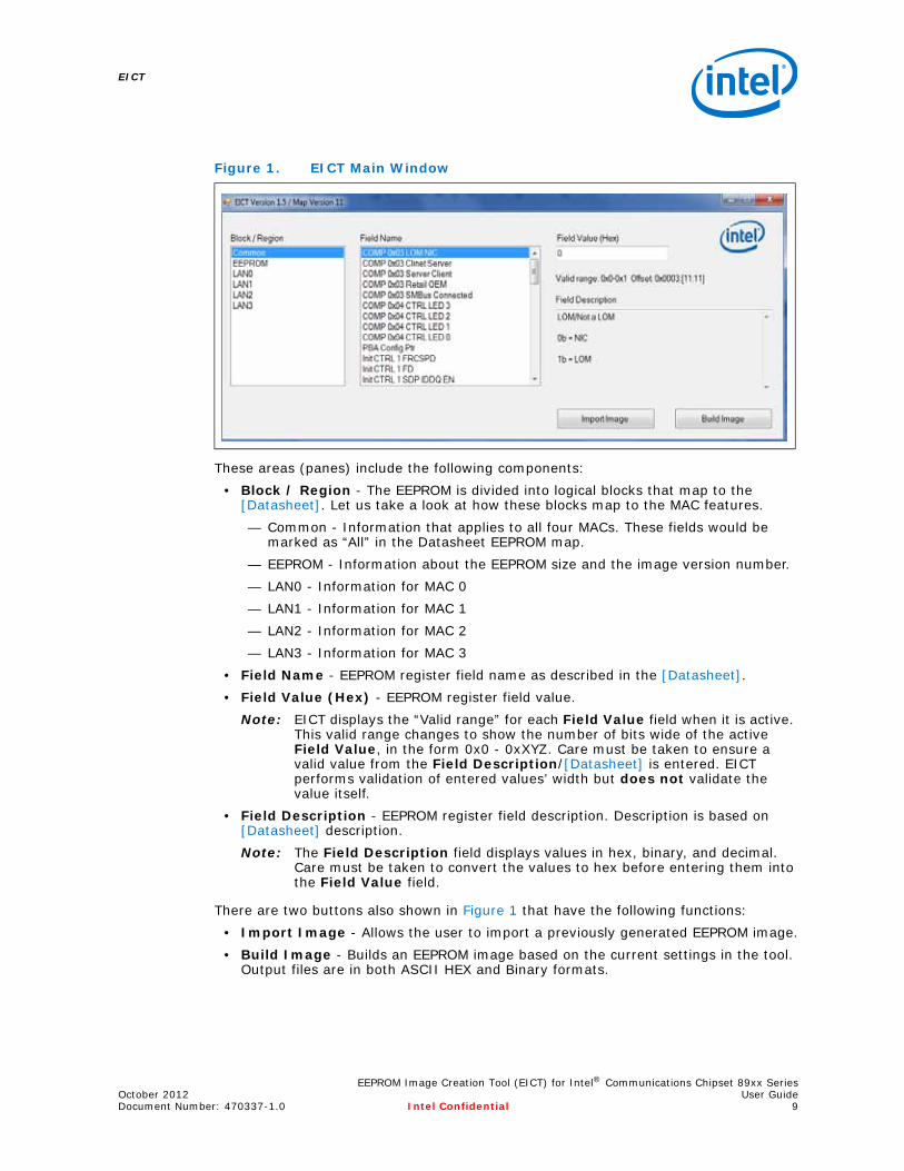
The main window for EICT is divided into four distinct areas, as shown in Figure 1.
EEPROM Image Creation Tool (EICT) for Intel® Communications Chipset 89xx SeriesOctober 2012 User GuideDocument Number: 470337-1.0 Intel Confidential 9
EICT
These areas (panes) include the following components:• Block / Region - The EEPROM is divided into logical blocks that map to the
[Datasheet]. Let us take a look at how these blocks map to the MAC features.— Common - Information that applies to all four MACs. These fields would be
marked as “All” in the Datasheet EEPROM map.— EEPROM - Information about the EEPROM size and the image version number.— LAN0 - Information for MAC 0— LAN1 - Information for MAC 1— LAN2 - Information for MAC 2— LAN3 - Information for MAC 3
• Field Name - EEPROM register field name as described in the [Datasheet].• Field Value (Hex) - EEPROM register field value.
Note: EICT displays the “Valid range” for each Field Value field when it is active. This valid range changes to show the number of bits wide of the active Field Value, in the form 0x0 - 0xXYZ. Care must be taken to ensure a valid value from the Field Description/[Datasheet] is entered. EICT performs validation of entered values’ width but does not validate the value itself.
• Field Description - EEPROM register field description. Description is based on [Datasheet] description.Note: The Field Description field displays values in hex, binary, and decimal.
Care must be taken to convert the values to hex before entering them into the Field Value field.
There are two buttons also shown in Figure 1 that have the following functions:• Import Image - Allows the user to import a previously generated EEPROM image.• Build Image - Builds an EEPROM image based on the current settings in the tool.
Output files are in both ASCII HEX and Binary formats.
Figure 1. EICT Main Window
EICT
EEPROM Image Creation Tool (EICT) for Intel® Communications Chipset 89xx SeriesUser Guide October 201210 Intel Confidential Document Number: 470337-1.0
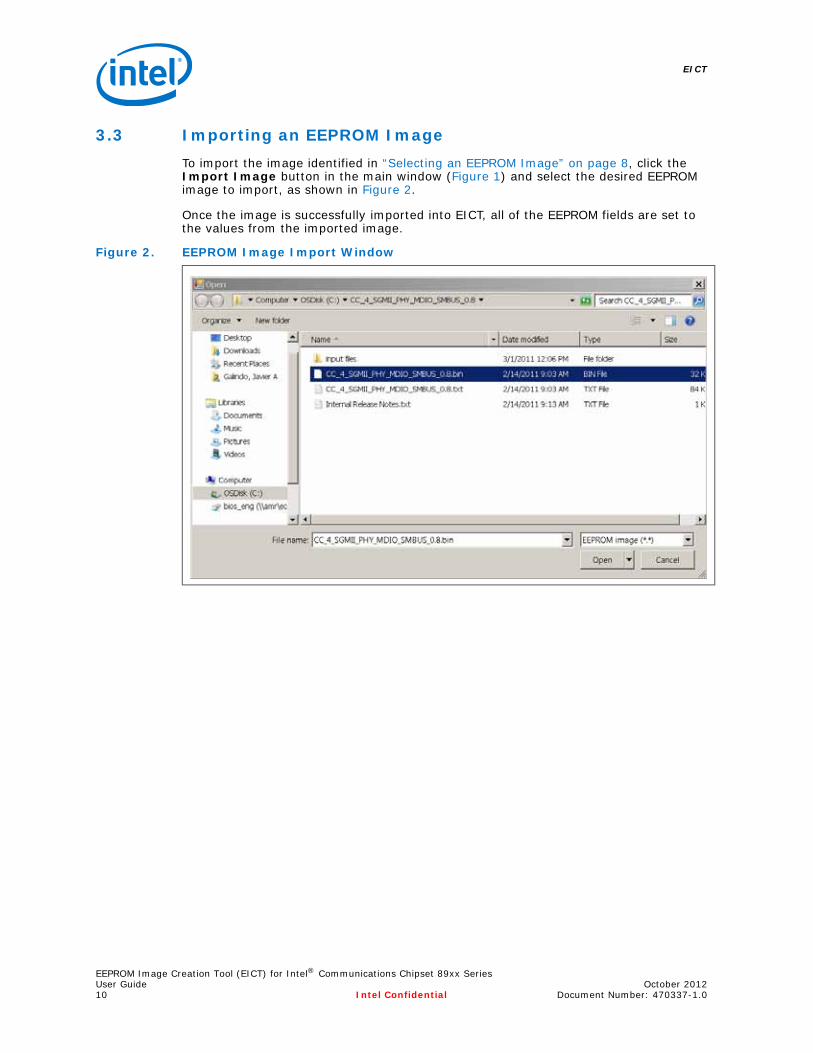
3.3 Importing an EEPROM ImageTo import the image identified in “Selecting an EEPROM Image” on page 8, click the Import Image button in the main window (Figure 1) and select the desired EEPROM image to import, as shown in Figure 2.
Once the image is successfully imported into EICT, all of the EEPROM fields are set to the values from the imported image.
Figure 2. EEPROM Image Import Window
EEPROM Image Creation Tool (EICT) for Intel® Communications Chipset 89xx SeriesOctober 2012 User GuideDocument Number: 470337-1.0 Intel Confidential 11
EICT
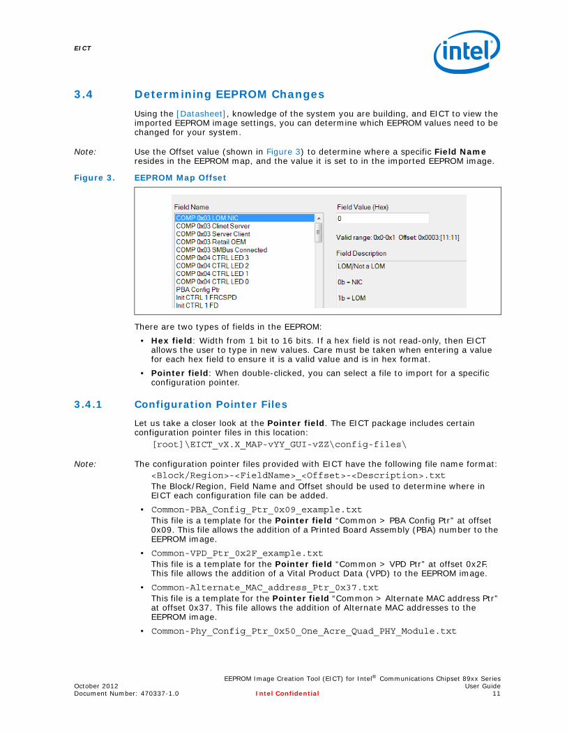
3.4 Determining EEPROM ChangesUsing the [Datasheet], knowledge of the system you are building, and EICT to view the imported EEPROM image settings, you can determine which EEPROM values need to be changed for your system.
Note: Use the Offset value (shown in Figure 3) to determine where a specific Field Name resides in the EEPROM map, and the value it is set to in the imported EEPROM image.
There are two types of fields in the EEPROM:• Hex field: Width from 1 bit to 16 bits. If a hex field is not read-only, then EICT
allows the user to type in new values. Care must be taken when entering a value for each hex field to ensure it is a valid value and is in hex format.
• Pointer field: When double-clicked, you can select a file to import for a specific configuration pointer.
3.4.1 Configuration Pointer Files
Let us take a closer look at the Pointer field. The EICT package includes certain configuration pointer files in this location:
[root]\EICT_vX.X_MAP-vYY_GUI-vZZ\config-files\
Note: The configuration pointer files provided with EICT have the following file name format:<Block/Region>-<FieldName>_<Offset>-<Description>.txt The Block/Region, Field Name and Offset should be used to determine where in EICT each configuration file can be added.
• Common-PBA_Config_Ptr_0x09_example.txt This file is a template for the Pointer field “Common > PBA Config Ptr” at offset 0x09. This file allows the addition of a Printed Board Assembly (PBA) number to the EEPROM image.
• Common-VPD_Ptr_0x2F_example.txt This file is a template for the Pointer field “Common > VPD Ptr” at offset 0x2F. This file allows the addition of a Vital Product Data (VPD) to the EEPROM image.
• Common-Alternate_MAC_address_Ptr_0x37.txt This file is a template for the Pointer field “Common > Alternate MAC address Ptr” at offset 0x37. This file allows the addition of Alternate MAC addresses to the EEPROM image.
• Common-Phy_Config_Ptr_0x50_One_Acre_Quad_PHY_Module.txt
Figure 3. EEPROM Map Offset

EICT
EEPROM Image Creation Tool (EICT) for Intel® Communications Chipset 89xx SeriesUser Guide October 201212 Intel Confidential Document Number: 470337-1.0
This file is used to configure the Intel PHY on the One Acre quad PHY module (shipped with the Customer Reference Board) and it can be used as a template for the Pointer field “Common > PHY Config Ptr” at offset 0x50. Use this file if PHY register writes are needed before software is loaded.
• Common-Sideband_Config_Ptr_0x57.txt This file is a template for the Pointer field “Common > Sideband Config Ptr” at offset 0x57. This file allows adding Sideband configuration information to the EEPROM image.
• LAN0-Pass_Thru_LAN_Config_Ptr_0x11.txt This file is a template for the Pointer field “LAN0 > LAN0 Pass Thru LAN Config Ptr” at offset 0x11. This file allows adding Pass Thru LAN information to the EEPROM image.
• LAN0-CSR_Auto_Config_Ptr_0x17-SerDes.txt This file should be selected for Pointer field “LAN0 > CSR Auto Config Ptr” at offset 0x17. Use this file if LAN 0 is being run in SerDes mode.
• LAN0-CSR_Auto_Config_Ptr_0x17-SGMII.txtThis file should be selected for Pointer field “LAN0 > CSR Auto Config Ptr” at offset 0x17. Use this file if all active LAN ports are being run in SGMII mode.
• LAN0-CSR_Auto_Config_Ptr_0x17-SGMII_and_SerDes.txt This file should be selected for Pointer field “LAN0 > CSR Auto Config Ptr” at offset 0x17. Use this file if LAN 0 is being run in SGMII mode and LAN 1, 2 or 3 is in SerDes mode.
• LAN1-Pass_Thru_LAN_Config_Ptr_0x91.txt This file is a template for the Pointer field “LAN1 > LAN1 Pass Thru LAN Config Ptr” at offset 0x91. This file allows adding Pass Thru LAN information to the EEPROM image.
• LAN1-CSR_Auto_Config_Ptr_0x97-SerDes.txt This file should be selected for Pointer field “LAN1 > CSR Auto Config Ptr” at offset 0x97. Use this file if LAN 1 is being run in SerDes mode.
• LAN1-CSR_Auto_Config_Ptr_0x97-SGMII.txt This file should be selected for Pointer field “LAN1 > CSR Auto Config Ptr” at offset 0x97. Use this file if all active LAN ports are being run in SGMII mode.
• LAN1-CSR_Auto_Config_Ptr_0x97-SGMII_and_SerDes.txt This file should be selected for Pointer field “LAN1 > CSR Auto Config Ptr” at offset 0x97. Use this file if LAN 1 is being run in SGMII mode and LAN 0, 2 or 3 is in SerDes mode.
• LAN2-Pass_Thru_LAN_Config_Ptr_0xD1.txt This file is a template for the Pointer field “LAN2 > LAN2 Pass Thru LAN Config Ptr” at offset 0xD1. This file allows adding Pass Thru LAN information to the EEPROM image.
• LAN2-CSR_Auto_Config_Ptr_0xD7-SerDes.txt This file should be selected for Pointer field “LAN2 > CSR Auto Config Ptr” at offset 0xD7. Use this file if LAN 2 is being run in SerDes mode.
• LAN2-CSR_Auto_Config_Ptr_0xD7-SGMII.txt This file should be selected for Pointer field “LAN2 > CSR Auto Config Ptr” at offset 0xD7. Use this file if all active LAN ports are being run in SGMII mode.
• LAN2-CSR_Auto_Config_Ptr_0xD7-SGMII_and_SerDes.txt This file should be selected for Pointer field “LAN2 > CSR Auto Config Ptr” at offset 0xD7. Use this file if LAN 2 is being run in SGMII mode and LAN 0, 1 or 3 is in SerDes mode.

EEPROM Image Creation Tool (EICT) for Intel® Communications Chipset 89xx SeriesOctober 2012 User GuideDocument Number: 470337-1.0 Intel Confidential 13
EICT
• LAN3-Pass_Thru_LAN_Config_Ptr_0x111.txt This file is a template for the Pointer field “LAN3 > LAN3 Pass Thru LAN Config Ptr” at offset 0x111. This file allows adding Pass Thru LAN information to the EEPROM image.
• LAN3-CSR_Auto_Config_Ptr_0x117-SerDes.txt This file should be selected for Pointer field “LAN3 > CSR Auto Config Ptr” at offset 0x117. Use this file if LAN 3 is being run in SerDes mode.
• LAN3-CSR_Auto_Config_Ptr_0x117-SGMII.txt This file should be selected for Pointer field “LAN3 > CSR Auto Config Ptr” at offset 0x117. Use this file if all active LAN ports are being run in SGMII mode.
• LAN3-CSR_Auto_Config_Ptr_0x117-SGMII_and_SerDes.txt This file should be selected for Pointer field “LAN3 > CSR Auto Config Ptr” at offset 0x117. Use this file if LAN 3 is being run in SGMII mode and LAN 0, 1 or 2 is in SerDes mode.
Caution: You should never modify the CSR Auto Config Power Up Ptr configuration files.
Note: The _C, _B and _A in the filenames indicates which stepping of the chipset each file should be used with.
• LAN0-CSR_Auto_Config_Power_Up_Ptr_0x27-PCIe-Top_C.txt • LAN0-CSR_Auto_Config_Power_Up_Ptr_0x27-PCIe-Top_B.txt • LAN0-CSR_Auto_Config_Power_Up_Ptr_0x27-PCIe-Top_A.txt • LAN0-CSR_Auto_Config_Power_Up_Ptr_0x27-Middle_C.txt • LAN0-CSR_Auto_Config_Power_Up_Ptr_0x27-Middle_B.txt • LAN0-CSR_Auto_Config_Power_Up_Ptr_0x27-Middle_A.txt • LAN0-CSR_Auto_Config_Power_Up_Ptr_0x27-CSR-Bottom_C.txt • LAN0-CSR_Auto_Config_Power_Up_Ptr_0x27-CSR-Bottom_B.txt • LAN0-CSR_Auto_Config_Power_Up_Ptr_0x27-CSR-Bottom_A.txt
These files are loaded into Pointer field “LAN0 > LAN0 CSR Auto Config Power Up Ptr” at offset 0x27 with the “Top” file at the top of the load screen, “Middle” file in the middle of the load screen, and the “Bottom” file at the bottom of the load screen.
• LAN1-CSR_Auto_Config_Power_Up_Ptr_0xA7-Top_C.txt • LAN1-CSR_Auto_Config_Power_Up_Ptr_0xA7-Top_B.txt • LAN1-CSR_Auto_Config_Power_Up_Ptr_0xA7-Top_A.txt • LAN1-CSR_Auto_Config_Power_Up_Ptr_0xA7-CSR-Bottom.txt
These files are loaded into Pointer field “LAN1 > LAN1 CSR Auto Config Power Up Ptr” at offset 0xA7 with the “Top” file at the top of the load screen and the “Bottom” file at the bottom of the load screen.
• LAN2-CSR_Auto_Config_Power_Up_Ptr_0xE7-Top_C.txt • LAN2-CSR_Auto_Config_Power_Up_Ptr_0xE7-Top_B.txt • LAN2-CSR_Auto_Config_Power_Up_Ptr_0xE7-Top_A.txt • LAN2-CSR_Auto_Config_Power_Up_Ptr_0xE7-CSR-Bottom.txt
These files are loaded into Pointer field “LAN2 > LAN2 CSR Auto Config Power Up Ptr” at offset 0xE7 with the “Top” file at the top of the load screen and the “Bottom” file at the bottom of the load screen.
• LAN3-CSR_Auto_Config_Power_Up_Ptr_0x127-Top_C.txt
EICT
EEPROM Image Creation Tool (EICT) for Intel® Communications Chipset 89xx SeriesUser Guide October 201214 Intel Confidential Document Number: 470337-1.0
• LAN3-CSR_Auto_Config_Power_Up_Ptr_0x127-Top_B.txt • LAN3-CSR_Auto_Config_Power_Up_Ptr_0x127-Top_A.txt • LAN3-CSR_Auto_Config_Power_Up_Ptr_0x127-CSR-Bottom.txt
These files are loaded into Pointer field “LAN3 > LAN3 CSR Auto Config Power Up Ptr” at offset 0x127 with the “Top” file at the top of the load screen and the “Bottom” file at the bottom of the load screen.
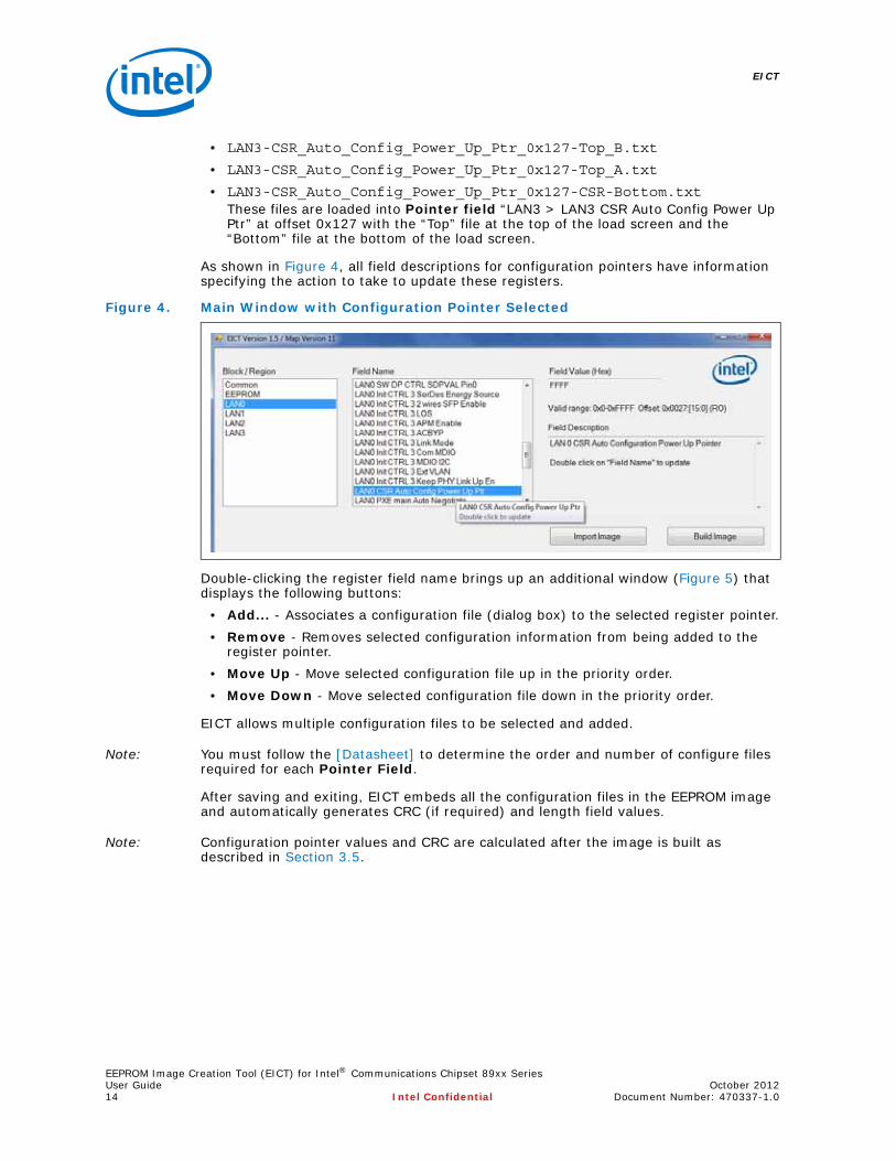
As shown in Figure 4, all field descriptions for configuration pointers have information specifying the action to take to update these registers.
Double-clicking the register field name brings up an additional window (Figure 5) that displays the following buttons:
• Add... - Associates a configuration file (dialog box) to the selected register pointer.• Remove - Removes selected configuration information from being added to the
register pointer.• Move Up - Move selected configuration file up in the priority order.• Move Down - Move selected configuration file down in the priority order.
EICT allows multiple configuration files to be selected and added.
Note: You must follow the [Datasheet] to determine the order and number of configure files required for each Pointer Field.
After saving and exiting, EICT embeds all the configuration files in the EEPROM image and automatically generates CRC (if required) and length field values.
Note: Configuration pointer values and CRC are calculated after the image is built as described in Section 3.5.
Figure 4. Main Window with Configuration Pointer Selected
EEPROM Image Creation Tool (EICT) for Intel® Communications Chipset 89xx SeriesOctober 2012 User GuideDocument Number: 470337-1.0 Intel Confidential 15
EICT
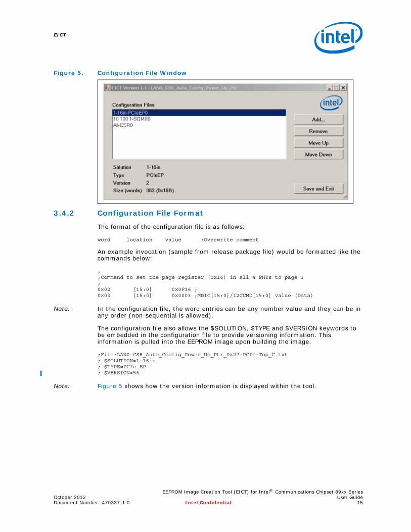
3.4.2 Configuration File Format
The format of the configuration file is as follows:
word location value ;Overwrite comment
An example invocation (sample from release package file) would be formatted like the commands below:
;;Command to set the page register (0x16) in all 4 PHYs to page 3;0x02 [15:0] 0x0F16 ;0x03 [15:0] 0x0003 ;MDIC[15:0]/I2CCMD[15:0] value (Data)
Note: In the configuration file, the word entries can be any number value and they can be in any order (non-sequential is allowed).
The configuration file also allows the $SOLUTION, $TYPE and $VERSION keywords to be embedded in the configuration file to provide versioning information. This information is pulled into the EEPROM image upon building the image.
;File:LAN0-CSR_Auto_Config_Power_Up_Ptr_0x27-PCIe-Top_C.txt ; $SOLUTION=1-16in; $TYPE=PCIe EP; $VERSION=56
Note: Figure 5 shows how the version information is displayed within the tool.
Figure 5. Configuration File Window
EICT
EEPROM Image Creation Tool (EICT) for Intel® Communications Chipset 89xx SeriesUser Guide October 201216 Intel Confidential Document Number: 470337-1.0
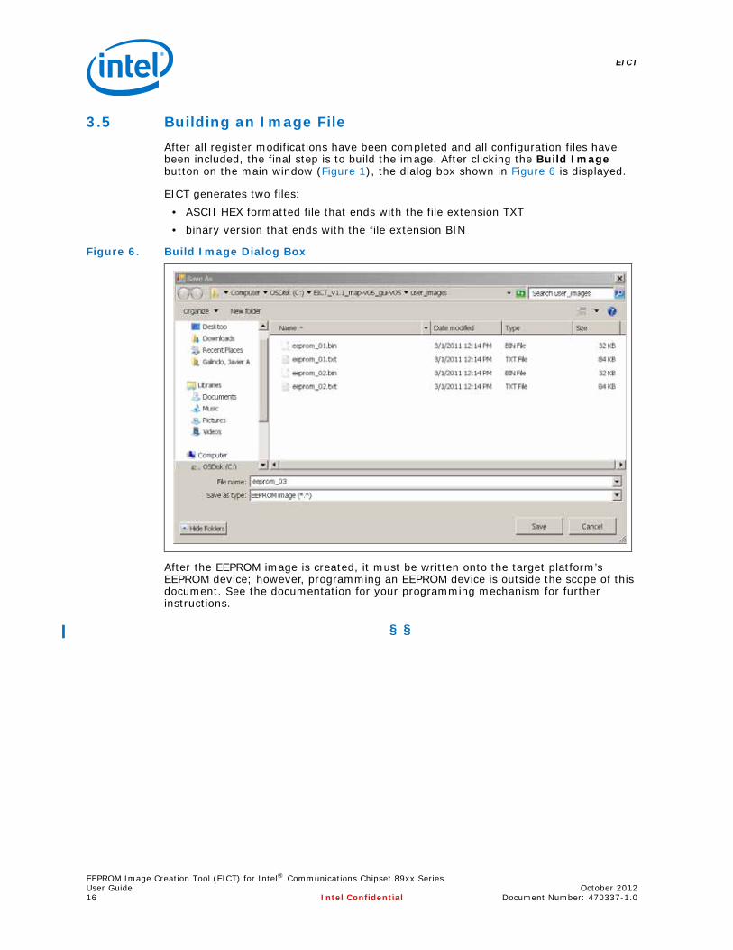
3.5 Building an Image FileAfter all register modifications have been completed and all configuration files have been included, the final step is to build the image. After clicking the Build Image button on the main window (Figure 1), the dialog box shown in Figure 6 is displayed.
EICT generates two files:• ASCII HEX formatted file that ends with the file extension TXT • binary version that ends with the file extension BIN
After the EEPROM image is created, it must be written onto the target platform’s EEPROM device; however, programming an EEPROM device is outside the scope of this document. See the documentation for your programming mechanism for further instructions.
§ §
Figure 6. Build Image Dialog Box