Effects of cavitation in a nozzle on liquid jet atomization · Effects of cavitation in a nozzle...
8
Effects of cavitation in a nozzle on liquid jet atomization Akira Sou * , Shigeo Hosokawa, Akio Tomiyama Faculty of Engineering, Kobe University, 1-1 Rokkodai, Nada, Kobe 657-8501, Japan Received 24 April 2006; received in revised form 6 November 2006 Available online 26 March 2007 Abstract Cavitation in two-dimensional (2D) nozzles and liquid jet in the vicinity of the nozzle exit were visualized using high-speed cameras to investigate the effects of cavitation on liquid jet under various conditions of cavitation and Reynolds numbers r and Re. Liquid velocity in the nozzle was measured using a laser Doppler velocimetry to examine the effects of cavitation on the flow in the nozzle and liquid jet. As a result, the following conclusions were obtained: (1) cavitation in the nozzles and liquid jet can be classified into the four regimes: (no cavitation, wavy jet), (developing cavitation, wavy jet), (super cavitation, spray) and (hydraulic flip, flipping jet), (2) liquid jet near the nozzle exit depends on cavitation regime, (3) cavitation and liquid jet are not strongly affected by Re but by r, and (4) strong turbulence induced by the collapse of cavitation clouds near the exit plays an important role in ligament formation. Ó 2007 Elsevier Ltd. All rights reserved. Keywords: Cavitation; Liquid jet; Atomization; Visualization; Ligament; Internal flow 1. Introduction It has been pointed out through a number of experimen- tal studies [1–5] that cavitation takes place in the nozzle of pressure atomizers, such as fuel injectors for diesel engines and rocket engines, and affects the characteristics of a dis- charged liquid jet. Hiroyasu et al. [1] showed that liquid jet atomization was promoted when cavitation extended from the inlet to the exit of a nozzle. Since the shapes of the noz- zles used in most of the previous studies have been cylindri- cal [1–5], it has been difficult to measure liquid velocity, turbulence intensity and radial distribution of cavitation bubbles in nozzles. Hence, several studies have been carried out using two-dimensional (2D) nozzles for visualization of detailed cavitation behavior [6–8]. However systematic observations of cavitation including incipient cavitation and well-developed cavitation have not been carried out yet. Recently some attempts have been made to measure the velocity in the nozzle which might play an important role in liquid jet atomization [9–12]. However the liquid velocity and its fluctuation under well-developed cavitation condition have not been measured yet. Hence, the mecha- nism of atomization enhancement by cavitation has not been clarified yet. In the present study, cavitation in 2D nozzles and liquid jet in the vicinity of the nozzle exit were visualized using a digital camera and high-speed video cameras under various conditions of Reynolds and cavitation numbers to examine the effects of the two dimensionless numbers on cavitation and liquid jet and to investigate the atomization enhance- ment mechanism by cavitation. Liquid velocity in the 2D nozzle was measured by using a laser Doppler velocimetry (LDV) to investigate the effects of cavitation on the flow in the nozzle and liquid jet atomization. 2. Experimental setup 2.1. Liquid injection system Schematic of experimental setup is shown in Fig. 1. Filtered tap water or light oil was discharged from 2D noz- zles into ambient air by the plunger pump through the cylindrical air separation tank of 90 mm in inner diameter 0017-9310/$ - see front matter Ó 2007 Elsevier Ltd. All rights reserved. doi:10.1016/j.ijheatmasstransfer.2006.12.033 * Corresponding author. Tel./fax: +81 78 803 6108. E-mail address: [email protected] (A. Sou). www.elsevier.com/locate/ijhmt International Journal of Heat and Mass Transfer 50 (2007) 3575–3582
Transcript of Effects of cavitation in a nozzle on liquid jet atomization · Effects of cavitation in a nozzle...

www.elsevier.com/locate/ijhmt
International Journal of Heat and Mass Transfer 50 (2007) 3575–3582
Effects of cavitation in a nozzle on liquid jet atomization
Akira Sou *, Shigeo Hosokawa, Akio Tomiyama
Faculty of Engineering, Kobe University, 1-1 Rokkodai, Nada, Kobe 657-8501, Japan
Received 24 April 2006; received in revised form 6 November 2006Available online 26 March 2007
Abstract
Cavitation in two-dimensional (2D) nozzles and liquid jet in the vicinity of the nozzle exit were visualized using high-speed cameras toinvestigate the effects of cavitation on liquid jet under various conditions of cavitation and Reynolds numbers r and Re. Liquid velocityin the nozzle was measured using a laser Doppler velocimetry to examine the effects of cavitation on the flow in the nozzle and liquid jet.As a result, the following conclusions were obtained: (1) cavitation in the nozzles and liquid jet can be classified into the four regimes: (nocavitation, wavy jet), (developing cavitation, wavy jet), (super cavitation, spray) and (hydraulic flip, flipping jet), (2) liquid jet near thenozzle exit depends on cavitation regime, (3) cavitation and liquid jet are not strongly affected by Re but by r, and (4) strong turbulenceinduced by the collapse of cavitation clouds near the exit plays an important role in ligament formation.� 2007 Elsevier Ltd. All rights reserved.
Keywords: Cavitation; Liquid jet; Atomization; Visualization; Ligament; Internal flow
1. Introduction
It has been pointed out through a number of experimen-tal studies [1–5] that cavitation takes place in the nozzle ofpressure atomizers, such as fuel injectors for diesel enginesand rocket engines, and affects the characteristics of a dis-charged liquid jet. Hiroyasu et al. [1] showed that liquid jetatomization was promoted when cavitation extended fromthe inlet to the exit of a nozzle. Since the shapes of the noz-zles used in most of the previous studies have been cylindri-cal [1–5], it has been difficult to measure liquid velocity,turbulence intensity and radial distribution of cavitationbubbles in nozzles. Hence, several studies have been carriedout using two-dimensional (2D) nozzles for visualization ofdetailed cavitation behavior [6–8]. However systematicobservations of cavitation including incipient cavitationand well-developed cavitation have not been carried outyet. Recently some attempts have been made to measurethe velocity in the nozzle which might play an importantrole in liquid jet atomization [9–12]. However the liquid
0017-9310/$ - see front matter � 2007 Elsevier Ltd. All rights reserved.
doi:10.1016/j.ijheatmasstransfer.2006.12.033
* Corresponding author. Tel./fax: +81 78 803 6108.E-mail address: [email protected] (A. Sou).
velocity and its fluctuation under well-developed cavitationcondition have not been measured yet. Hence, the mecha-nism of atomization enhancement by cavitation has notbeen clarified yet.
In the present study, cavitation in 2D nozzles and liquidjet in the vicinity of the nozzle exit were visualized using adigital camera and high-speed video cameras under variousconditions of Reynolds and cavitation numbers to examinethe effects of the two dimensionless numbers on cavitationand liquid jet and to investigate the atomization enhance-ment mechanism by cavitation. Liquid velocity in the 2Dnozzle was measured by using a laser Doppler velocimetry(LDV) to investigate the effects of cavitation on the flow inthe nozzle and liquid jet atomization.
2. Experimental setup
2.1. Liquid injection system
Schematic of experimental setup is shown in Fig. 1.Filtered tap water or light oil was discharged from 2D noz-zles into ambient air by the plunger pump through thecylindrical air separation tank of 90 mm in inner diameter
Nomenclature
Lcav streamwise length of cavitation zoneL�cav normalized cavitation length (=Lcav/LN)LN nozzle length [mm]Pa atmospheric pressure [Pa]Pv vapor saturation pressure [Pa]Re Reynolds numbert time [ls]tN nozzle thickness [mm]TL liquid temperature [K]VN mean liquid velocity in a nozzle [m/s]WN nozzle width [mm]x horizontal distance from nozzle center [mm]y vertical distance from nozzle inlet [mm]
Greek symbols
c surface tension [N/m]mL liquid kinematic viscosity [m2/s]h spray angle [deg]qL liquid density [kg/m3]r the cavitation number
Subscripts
N nozzleL liquid
Flash Lamp
2D Nozzle
Digital Camera or High Speed Camera
Power Source
Plunger PumpGas-LiquidSeparation Tank
Fig. 1. Experimental setup.
3576 A. Sou et al. / International Journal of Heat and Mass Transfer 50 (2007) 3575–3582
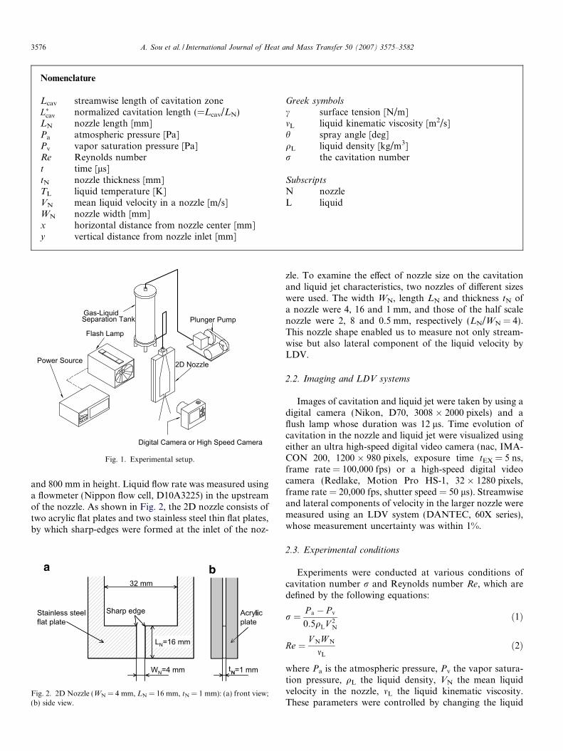
and 800 mm in height. Liquid flow rate was measured usinga flowmeter (Nippon flow cell, D10A3225) in the upstreamof the nozzle. As shown in Fig. 2, the 2D nozzle consists oftwo acrylic flat plates and two stainless steel thin flat plates,by which sharp-edges were formed at the inlet of the noz-
32 mm
WN=4 mm
LN=16 mm
Sharp edgeStainless steelflat plate
N=1 mm
Acrylicplate
LN=16 mm
N
li
t
Fig. 2. 2D Nozzle (WN = 4 mm, LN = 16 mm, tN = 1 mm): (a) front view;(b) side view.
zle. To examine the effect of nozzle size on the cavitationand liquid jet characteristics, two nozzles of different sizeswere used. The width WN, length LN and thickness tN ofa nozzle were 4, 16 and 1 mm, and those of the half scalenozzle were 2, 8 and 0.5 mm, respectively (LN/WN = 4).This nozzle shape enabled us to measure not only stream-wise but also lateral component of the liquid velocity byLDV.
2.2. Imaging and LDV systems
Images of cavitation and liquid jet were taken by using adigital camera (Nikon, D70, 3008 � 2000 pixels) and aflush lamp whose duration was 12 ls. Time evolution ofcavitation in the nozzle and liquid jet were visualized usingeither an ultra high-speed digital video camera (nac, IMA-CON 200, 1200 � 980 pixels, exposure time tEX = 5 ns,frame rate = 100,000 fps) or a high-speed digital videocamera (Redlake, Motion Pro HS-1, 32 � 1280 pixels,frame rate = 20,000 fps, shutter speed = 50 ls). Streamwiseand lateral components of velocity in the larger nozzle weremeasured using an LDV system (DANTEC, 60X series),whose measurement uncertainty was within 1%.
2.3. Experimental conditions
Experiments were conducted at various conditions ofcavitation number r and Reynolds number Re, which aredefined by the following equations:
r ¼ P a � P v
0:5qLV 2N
ð1Þ
Re ¼ V NW N
mL
ð2Þ
where Pa is the atmospheric pressure, Pv the vapor satura-tion pressure, qL the liquid density, VN the mean liquidvelocity in the nozzle, mL the liquid kinematic viscosity.These parameters were controlled by changing the liquid

Table 1Typical experimental conditions and flow regimes (water, TL = 292 K,WN = 4 mm)
Reynoldsnumber, Re
Cavitationnumber, r
Cavitation innozzle
Liquid jet
45,000 1.57 No cavitation Wavy jet50,000 1.2758,000 0.94 Developing
cavitation64,000 0.7868,000 0.69 Super cavitation Spray70,000 0.6576,000 0.55 Hydraulic flip Flipping jet78,000 0.52
A. Sou et al. / International Journal of Heat and Mass Transfer 50 (2007) 3575–3582 3577
flow rate, fluid properties and nozzle size. Typical experi-mental conditions are listed in Table 1 (water, TL =292 K, WN = 4 mm). The maximum error of measuredflow rate was 2.7% for the larger nozzle and 3.7% for thehalf scale nozzle. The concentration of dissolved oxygen(DO) in water was 9.0 mg/l, when the water temperatureTL was 291 K. In more than 100 images of the flow inthe nozzle (spatial resolutions were 2 lm/pixel) no micro-bubbles or solid particles were observed in the upstreamof cavitation zone. The LDV measurement could not becarried out unless silicone carbide (SiC) particles of 3 lmin mean diameter were added as seeding particles (2.5g/m3). The effects of the added particles on cavitation werenegligible [13].
Fig. 4. Distributions of mean liquid velocity in a 2D nozzle (water,TL = 291 K, WN = 4 mm): (a) r = 1.27, Re = 50,000, (b) r = 0.95,Re = 58,000, (c) r = 0.78, Re = 64,000, (d) r = 0.65, Re = 70,000.
3. Results and discussion
3.1. Flow regimes
Flow regimes in the nozzle and liquid jet near the nozzleexit are summarized in Fig. 3 and Table 1 (water,TL = 292 K, WN = 4 mm). When r > 1.2, cavitation bub-bles were not observed and liquid jet took the form of‘‘wavy jet”. For 0.75 6 r 6 1.2, cavitation bubble cloudsappeared in the upper half of the nozzle. We defined this
σ =0.78Re=6400
σ=0.94Re=58000
σ=1.27Re=50000
σ =1.57Re=45000
0
5
mm
10
15
0
5
mm
10
15
liquid jet
developing cavitationo cavitationcavitationin a nozzle
wavy jet
Fig. 3. Images of cavitation in a 2D nozzle and liquid jet (w
type of the cavitation as ‘‘developing cavitation”. In devel-oping cavitation, liquid jet near the exit was wavy jet. For0.55 < r < 0.75, cavitation zone extended from the inlet tojust above the nozzle exit (normalized mean cavitation
0σ =0.65
Re=70000σ =0.55
Re=76000
spray flipping jet
n super cavitation hydraulic flip
ater, TL = 292 K, WN = 4 mm, flush duration = 12 ls).

3578 A. Sou et al. / International Journal of Heat and Mass Transfer 50 (2007) 3575–3582
length L�cav ’ 0:8–0:9, where the definition of L�cav will bedescribed later). We named this regime ‘‘super cavitation”.In super cavitation, liquid jet atomization was enhanced,i.e., ligaments and droplets appeared (‘‘spray”) and thespray angle increased. Further decrease in r (r < 0.55)resulted in the formation of ‘‘hydraulic flip” and ‘‘flippingjet”, in which liquid flow separated at one inlet edge anddid not reattach to the side wall. The condition of the incip-ient cavitation has been examined in our previous report[13].
Fig. 4 shows the distribution of mean liquid velocity in anozzle of 4 mm in width. We confirmed that cavitationappeared within the separated boundary layer (SBL). Thedistribution of mean velocity was not uniform just belowthe cavitation zone, i.e. the reattachment point of SBL,however it became almost uniform near the nozzle exit inno cavitation or developing cavitation regimes.
3.2. Effects of r and Re on cavitation and liquid jet
The Reynolds number Re increases with water tempera-ture TL since kinematic viscosity mL of water decreases withincreasing TL, while the cavitation number r does not
0.5 1.0 1.5
0.5
1.0
1.5
Rey
nold
s nu
mbe
r Re
no cav. dev. cav. sup. cav. hydr. flp.
0.5 1.0 1.5
0.5
1.0
1.5[ ×105 ]
[ ×105 ]
cavitation number σ
cavitation number σ
Rey
nold
s nu
mbe
r Re
wavy jet spray flip. jet
Fig. 5. Effects of r and Re on cavitation and liquid jet (water,WN = 4 mm, TL = 293, 303, 313, 333 K): (a) cavitation regime map; (b)liquid jet regime map.
change a lot by varying TL. To examine the influences ofr and Re on cavitation and liquid jet, observations wereconducted under various TL conditions (293 6 TL 6
333 K). Regimes of cavitation and liquid jet are shown inFig. 5a and b, respectively. The spray region on the liquidjet regime map corresponds to the super cavitation regionon the cavitation regime map, which means that the forma-tion of super cavitation enhances liquid jet atomization.Since the transition from developing to super cavitationdoes not strongly depend on Re but on r, the transitionfrom wavy jet to spray also depend on r.
The normalized cavitation lengths (=streamwise lengthof cavitation zone Lcav/nozzle length LN) were measuredfrom the nozzle images in the cases of the larger nozzle,the half scale nozzle (TL = 293 K) and light oil(WN = 4 mm). The effects of Re and r on the averagedvalue L�cav of the normalized cavitation lengths are shownin Fig. 6a and b, respectively. The maximum fluctuationof the normalized cavitation length was 0.05 for developingcavitation and 0.15 for super cavitation. Regime transitionin the cases of the half scale nozzle and light oil showed thesame trends as that in the larger nozzle. The L�cav did notstrongly depend on Re but on r.
Spray angles in the vicinity of the nozzle exit (15 mmdownstream of the nozzle exit) were measured from theimages as shown in Fig. 7, and the averaged values h areplotted against L�cav in Fig. 8. The maximum fluctuationof measured spray angle was 1.8� for developing cavitationand 5.4� for super cavitation. When the value of L�cav isabout 0.8–0.9, i.e. in super cavitation, h increases as shownin Fig. 8. The difference in spray angle between water (sur-
0.0 0.5 1.0 1.5 2.0[×105 ]
0.0
0.2
0.4
0.6
0.8
1.0
Re
L cav
*
TL=293KTL=303KTL=313KTL=333KWN=2mmlight oil
0 1 20.0
0.2
0.4
0.6
0.8
1.0
σ
L cav
*
TL=293KTL=303KTL=313KTL=333KWN=2mmlight oil
Fig. 6. Effects of Re and r on normalized cavitation length L�cav: (a) effectsof Re on L�cav; (b) effects of r on L�cav.

15 mm
Spray angle
Nozzle
Flow
Nozzle
Fig. 7. Spray angle h.
0 0.2 0.4 0.6 0.8 10
5
10
15
Lcav*
Spra
y an
gle
(deg
.)
TL=293KTL=303KTL=313KTL=333KWN=2mmlight oil
Fig. 8. Effects of L�cav on spray angle h.
0 1 2-2
-1
0
1
2
x [mm]
σ=0.78σ=0.65
1 2
1
2
3
4
0
σ=0.78σ=0.65
x [mm]
u' [m
/s]
U [m
/s]
Fig. 9. Lateral component of velocity above the nozzle exit (water,TL = 291 K, WN = 4 mm, y = 15 mm): (a) mean velocity, (b) turbulenceintensity.
A. Sou et al. / International Journal of Heat and Mass Transfer 50 (2007) 3575–3582 3579
face tension c = 0.073 N/m), the half scale nozzle and lightoil (c = 0.03 N/m) for L�cav smaller than about 0.8 was dueto the difference in surface tension.
The lateral component of mean velocity U and the RMSof lateral component of velocity fluctuation u0 (turbulenceintensity) near the exit (distance from the inlet y =
Fig. 10. Collapse of cavitation clouds above the nozzle exit (water, TL =(a) visualized region, (b) t = 0 ls, (c) t = 30 ls, (d) t = 60 ls, (e) t = 90 ls, (f)
15 mm) are shown in Fig. 9 to examine the effects of cavi-tation on turbulence intensity and liquid jet. In developingcavitation (r = 0.78) the value of U near the exit was closeto zero and u0 was small. On the other hand, u0 in super cav-itation (r = 0.65) was large and the value of U was positive,i.e., the mean flow directed toward the side wall. The lateralflow and strong turbulence in super cavitation could be thedominant mechanisms to increase the spray angle and ini-tiate atomization.
3.3. Effects of cavitation collapse on ligament formation
Cavitation behavior near the nozzle exit in super cavita-tion was visualized using the ultra-high speed camera(tEX = 5 ns, 100,000 fps). Images of the collapse of cavita-tion cloud are shown in Fig. 10 (water, TL = 292 K,WN = 4 mm, r = 0.69). The collapse of cavitation cloudstook place intermittently. The collapse might cause a highturbulence intensity near the exit, and therefore affects theligament formation.
292 K, WN = 4 mm, r = 0.69, Re = 68,000, 2.5 lm/pixel, tEX = 5 ns):t = 120 ls.

2D nozzle
Highspeedcamera
Slanted acrylic plate
Visualized region
Liquid jet
2D nozzle
2D Nozzle
Slanted acrylic plate
Fig. 11. Experimental setup for the simultaneous visualization of cavita-tion and liquid jet: (a) top view; (b) front view.
Fig. 12. Simultaneous visualization of cavitation and liquid jet interface (w
3580 A. Sou et al. / International Journal of Heat and Mass Transfer 50 (2007) 3575–3582
To examine the relation between the collapse of cavita-tion cloud and ligament formation in super cavitation,cavitation and liquid jet interface were visualized simulta-neously with a high frame rate (20,000 fps). Since therefractive index of the acrylic plate of the nozzle is higherthan that of air, an acrylic plate was placed between theliquid jet and the camera to match the optical distances.In the high frame rate imaging, the image size was limitedto 32 � 1280 pixels. Hence, the acrylic plate was tilted tocapture both cavitation and jet interface within a narrowregion shown in Fig. 11.
Time series images of cavitation and liquid jet are shownin Fig. 12 (water, WN = 4 mm, TL = 293 K, r = 0.65,32 � 1280 pixels, 20,000 fps). If a high pressure caused by
ater, TL = 293 K, WN = 4 mm, r = 0.65, 32 � 1280 pixels, 20,000 fps).

10-1 100 101101
102
103
f [kHz]
inte
nsity
Fig. 13. Power spectrum of image data (r = 0.65, super cavitation).
10-1 100 101105
106
f [kHz]
inte
nsity
10-1 100 101105
106
f [kHz]
inte
nsity
Fig. 15. Power spectrum of LDV data near the exit (y = 15 mm): (a)r = 0.78, developing cavitation; (b) r = 0.65, super cavitation.
A. Sou et al. / International Journal of Heat and Mass Transfer 50 (2007) 3575–3582 3581
the cavitation collapse is the dominant mechanism of theligament formation, a ligament may appear immediatelyafter the collapse. However a ligament did not alwaysappear when a collapse took place, and some ligamentsappeared when there were no cavitation collapses as shownin Fig. 12. The arrows in the figure represent the pathsmoving with mean liquid velocity in the nozzle VN. A liga-ment was formed, when a trace of cavitation collapse cameout with the velocity VN from the nozzle. By investigating10,000 images it was found that the frequencies of the shed-ding and collapse of cavitation clouds were about 1–4 kHzin the case of WN = 4 mm. Fig. 13 shows the power spec-trum of the mean CCD intensities in the region (32 �40 pixels) where cavitation clouds pass through (y =12 mm). A large intensity can be seen in the range of about1–4 kHz.
1 2
1
2
3
4
0x [mm]
u' [m
/s]
y=0.5mm y=8mm y=13mm
1 2
1
2
3
4
0x [mm]
u' [m
/s]
y=0.5mm y=4.05mm y=13mm
1 2
1
2
3
4
0x [mm]
u' [m
/s]
y=0.5mm y=8.83mm y=13mm y=15mm
1 2
1
2
3
4
0
u' [m
/s]
x [mm]
y=0.5mm y=8mm y=13mm y=15mm
c d
Fig. 14. RMS of lateral component of velocity fluctuation: (a) r = 1.27,no cavitation; (b) r = 0.95, developing cavitation; (c) r = 0.78, developingcavitation; (d) r = 0.65, super cavitation.
The RMS of lateral component of velocity fluctuation u0
is plotted in Fig. 14. As shown in the figure, strong turbu-lence appeared just below the cavitation collapse point(y = 4.05 mm for r = 0.95, y = 8.83 mm for r = 0.78,y = 15 mm for r = 0.65), and the turbulence decreased asy increased. This indicates that turbulence intensityincreases just below the collapse point, and the strong tur-bulence reaches the nozzle exit only in the case of supercavitation. The power spectrum of the lateral componentof the measured velocity near the exit (y = 15 mm) isshown in Fig. 15. A large intensity appeared in the rangeof about 1–4 kHz for super cavitation (r = 0.65). The fre-quency range agreed with that of the cavitation sheddingand the ligament formation. Hence, we could confirm thatthe strong turbulence induced by the collapse of cavitationclouds near the exit plays an important role in ligamentformation.
4. Conclusions
Cavitation in two-dimensional (2D) transparent nozzlesand liquid jets in the vicinity of the nozzle exit were visual-ized using a digital camera, an ultra high-speed video cam-era and a high-speed video camera. Liquid velocity in the2D nozzle was measured using a LDV system. The effectsof the cavitation number r and the Reynolds number Re
on cavitation in the nozzle and liquid jet were examinedby varying the liquid flow rate, fluid properties and nozzlesize. Cavitation in the nozzle and ligament formation atliquid jet interface were simultaneously visualized using ahigh-speed camera to examine the mechanism of atomization

3582 A. Sou et al. / International Journal of Heat and Mass Transfer 50 (2007) 3575–3582
enhancement by cavitation. As a result, the following con-clusions were obtained.
(1) Cavitation in 2D nozzles and liquid jet are classifiedinto the following regimes: 1 – no cavitation, wavyjet; 2 – developing cavitation, wavy jet; 3 – super cav-itation, spray; and 4 – hydraulic flip, flipping jet.
(2) Liquid jet atomization near the nozzle exit dependson cavitation regime, i.e., ligament formation andspray angle depend on the normalized cavitationlength L�cav.
(3) Cavitation and a liquid jet near the nozzle exit are notstrongly affected by the Reynolds number Re but bythe cavitation number r.
(4) Strong turbulence induced by the collapse of cavita-tion clouds near the exit plays an important role inligament formation.
Acknowledgements
The authors would like to express their thanks toMr. Shinji Nigorikawa and Mr. Tatsutoshi Maeda. Thisstudy was supported by a Grant-in-Aid for ScientificResearch (# 16760129) of the Japan Ministry of Education,Culture, Science, Sports, and Technology (MEXT) and aGrant-in-Aid for Scientific Research (# 18560170) of theJapan Society for the Promotion Science (JSPS).
References
[1] H. Hiroyasu, M. Arai, M. Shimizu, Break-up length of a liquid jetand internal flow in a nozzle, Proc. ICLASS – 91 (1991) 275–282.
[2] H. Chaves, M. Knapp, A. Kubitzek, F. Obermeier, T. Schneider,Experimental study of cavitation in the nozzle hole of diesel injectorsusing transparent nozzles, SAE Paper, Paper No. 950290 (1991) 645–657.
[3] C. Soteriou, R. Andrews, M. Smith, Direct injection diesel sprays andthe effect of cavitation and hydraulic flip on atomization, SAE Paper,Paper No. 950080 (1995).
[4] L.C. Ganippa, G. Bark, S. Andersson, J. Chomiak, Comparison ofcavitation phenomena in transparent scale-up single-hole dieselnozzles, Proc. CAV2001 (2001) A9.005.
[5] N. Tamaki, M. Shimizu, H. Hiroyasu, Enhancement of the atomiza-tion of a liquid jet by cavitation in a nozzle hole, Atomization Sprays11 (2001) 125–137.
[6] M.E. Henry, S.H. Collicott, Visualization of internal flow in acavitating slot orifice, Atomization Sprays 10 (2000) 545–563.
[7] H. Iida, E. Matsumura, K. Tanaka, J. Senda, H. Fujimoto, R.R.Maly, Effect of internal flow in a simulated diesel injection nozzle onspray atomization, Proc. ICLASS 2000 (2000), CD-ROM.
[8] M. Daikoku, H. Furudate, H. Noda, T. Inamura, Effect of cavitationin the two-dimensional nozzle on liquid breakup process, Proc.ICLASS 2003 (2003), 17-6, CD-ROM.
[9] J. Walther, J.K. Schaller, R. Wirth, C. Tropea, Investigation ofinternal flow in transparent diesel injection nozzles using fluorescentparticle image velocimetry (FPIV), Proc. ICLASS 2000 (2000), CD-ROM.
[10] M. Gnirss, K. Heukelbach, C. Tropea, Influence of nozzle flow on theatomization of liquid sheets and round jets, in: Proc. DFG-PriorityProgram Atomization Spray Processes (2004) Paper No. 1.2.
[11] L. He, F. Ruiz, Effect of cavitation on flow and turbulence in plainorifices for highspeed atomization, Atomization Sprays 5–6 (1995)569–584.
[12] T. Oda, Y. Yasuda, Experimental investigation on structure ofcavitating flow and velocity field inside a 2-D hole nozzle, Proc.ICLASS 2003 (2003), 12-5, CD-ROM.
[13] A. Sou, A. Tomiyama, S. Hosokawa, S. Nigorikawa, T. Maeda,Cavitation in a two-dimensional nozzle and liquid jet atomization(LDV measurement of liquid velocity in a nozzle), JSME Int. J., Ser.B 49-4 (2006) 1253–1259.