
E•ect of load ratio and maximum stress intensity on the … · E•ect of load ratio and maximum...
19
Eect of load ratio and maximum stress intensity on the fatigue threshold in Ti–6Al–4V B.L. Boyce, R.O. Ritchie * Department of Materials Science and Engineering, University of California, Berkeley, CA 94720-1760, USA Received 14 February 2000; received in revised form 30 September 2000; accepted 2 October 2000 Abstract There has been a renewed interest of late in the mechanisms responsible for the influence of the load ratio, R, and the maximum stress intensity, K max , on the threshold for fatigue-crack growth, DK th . While mechanistic explanations in the past have largely focused on the role of crack closure, it is certainly not the only mechanism by which K max influences DK th . In this work, we examine the eect of a wide range of loading frequencies (m 50–1000 Hz) and load ratios (R 0:10–0:95) on fatigue-crack propagation and threshold behavior in a Ti–6Al–4V turbine blade alloy consisting of 60 vol% primary-a and 40 vol% lamellar a b. The data presented in this paper indicate that at K max values above 6 MPa p m(R > 0:5), where macroscopic crack closure is no longer detected in this alloy, DK th decreases approximately linearly with increasing K max . This result is discussed in terms of possible mechanistic explanations, including sustained- load cracking, microscopic near-tip closure, and static fracture modes, based on considerations of experimental evi- dence from both the current study and the literature. Ó 2000 Published by Elsevier Science Ltd. Keywords: Titanium alloys; Ti–6Al–4V; Fatigue threshold; Load ratio; Crack closure; Sustained-load cracking 1. Introduction The influence of load ratio, 1 R, on fatigue-crack propagation rates has been widely studied from both experimental (e.g. Refs. [1–6]) and analytical (e.g. Refs. [7,8]) viewpoints. Almost without exception, an increase in load ratio results in an increase in fatigue-crack propagation rate at a given applied cyclic stress- intensity, DK. Equivalently, the observed threshold stress-intensity range for fatigue-crack propagation, DK th , decreases as the (positive) load ratio is increased. Mechanistic explanations for such behavior have focused on (a) the presence of crack closure at low values of the minimum stress intensity, K min [1] or (b) the presence of static fracture modes as the maximum stress intensity, K max , approaches the fracture toughness, K Ic [9]. Engineering Fracture Mechanics 68 (2001) 129–147 www.elsevier.com/locate/engfracmech * Corresponding author. Tel.: +1-510-486-5798; fax: +1-510-486-4995. E-mail address: [email protected] (R.O. Ritchie). 1 Load ratio, R, is defined under fatigue loading conditions as the minimum applied load divided by the maximum applied load for any given loading cycle. 0013-7944/01/$ - see front matter Ó 2000 Published by Elsevier Science Ltd. PII:S0013-7944(00)00099-0
Transcript of E•ect of load ratio and maximum stress intensity on the … · E•ect of load ratio and maximum...

E�ect of load ratio and maximum stress intensity on the fatiguethreshold in Ti±6Al±4V
B.L. Boyce, R.O. Ritchie *
Department of Materials Science and Engineering, University of California, Berkeley, CA 94720-1760, USA
Received 14 February 2000; received in revised form 30 September 2000; accepted 2 October 2000
Abstract
There has been a renewed interest of late in the mechanisms responsible for the in¯uence of the load ratio, R, and the
maximum stress intensity, Kmax, on the threshold for fatigue-crack growth, DKth. While mechanistic explanations in the
past have largely focused on the role of crack closure, it is certainly not the only mechanism by which Kmax in¯uences
DKth. In this work, we examine the e�ect of a wide range of loading frequencies (m � 50±1000 Hz) and load ratios
(R � 0:10±0:95) on fatigue-crack propagation and threshold behavior in a Ti±6Al±4V turbine blade alloy consisting of
�60 vol% primary-a and �40 vol% lamellar a� b. The data presented in this paper indicate that at Kmax values above 6
MPap
m (R > 0:5), where macroscopic crack closure is no longer detected in this alloy, DKth decreases approximately
linearly with increasing Kmax. This result is discussed in terms of possible mechanistic explanations, including sustained-
load cracking, microscopic near-tip closure, and static fracture modes, based on considerations of experimental evi-
dence from both the current study and the literature. Ó 2000 Published by Elsevier Science Ltd.
Keywords: Titanium alloys; Ti±6Al±4V; Fatigue threshold; Load ratio; Crack closure; Sustained-load cracking
1. Introduction
The in¯uence of load ratio, 1 R, on fatigue-crack propagation rates has been widely studied from bothexperimental (e.g. Refs. [1±6]) and analytical (e.g. Refs. [7,8]) viewpoints. Almost without exception, anincrease in load ratio results in an increase in fatigue-crack propagation rate at a given applied cyclic stress-intensity, DK. Equivalently, the observed threshold stress-intensity range for fatigue-crack propagation,DKth, decreases as the (positive) load ratio is increased. Mechanistic explanations for such behavior havefocused on (a) the presence of crack closure at low values of the minimum stress intensity, Kmin [1] or (b) thepresence of static fracture modes as the maximum stress intensity, Kmax, approaches the fracture toughness,KIc [9].
Engineering Fracture Mechanics 68 (2001) 129±147
www.elsevier.com/locate/engfracmech
* Corresponding author. Tel.: +1-510-486-5798; fax: +1-510-486-4995.
E-mail address: [email protected] (R.O. Ritchie).1 Load ratio, R, is de®ned under fatigue loading conditions as the minimum applied load divided by the maximum applied load for
any given loading cycle.
0013-7944/01/$ - see front matter Ó 2000 Published by Elsevier Science Ltd.
PII: S00 1 3-7 9 44 (0 0 )0 00 9 9- 0

A common conception of the variation in the fatigue threshold with load ratio is shown in Fig. 1a.Schmidt and Paris [1] rationalized this behavior solely on the basis of the crack closure concept. Assumingthat both the closure-corrected e�ective fatigue threshold, DKeff ;th and the closure stress intensity, Kcl, arenot a�ected by load ratio, then there exists some critical load ratio, Rc at which Kmin � Kcl, such that:
DKeff ;th � Kmax;th ÿ Kcl < DKth; if R < Rc �Kmin;th < Kcl�;Kmax;th ÿ Kmin;th � DKth; if R > Rc �Kmin;th > Kcl�:
��1�
Under these conditions, the maximum stress intensity at threshold, Kmax;th, is independent of R below Rc
and the threshold stress-intensity range, DKth, is independent of R above Rc. Plotted as Kmax;th versus DKth,this transition manifests itself as a distinct `L' shape, as shown in Fig. 1b, highlighting that the value of DKth
is independent of Kmax when R > Rc where global closure is no longer e�ective. As a ®rst approximation, theSchmidt and Paris analysis seems to work moderately well, with many data sets showing this transition atload ratios similar to the critical load ratio condition, Rc, at which point Kmin � Kcl.
This behavior, however, is not universal, as shown by the compilation of data presented in Fig. 2. Inmost cases, the value of DKth is not invariant at R > Rc, but rather DKth decreases with increasing R (Fig. 1cand d), implying that either the Schmidt and Paris model is not properly described at R > Rc, or that thereare additional mechanisms acting in concert. It is this variation in DKth with increasing R > Rc, that isapparently independent of crack closure, which is the focus of the current work. We examine this behaviorin a Ti±6Al±4V alloy processed for turbine blade applications, and consider possible mechanistic expla-nations.
2. Background
The progressive downward trend of the threshold DKth with increasing load ratio at R > Rc was noted byD�oker [12] based on the fatigue study of Huthmann and Gossmann [13] on a high-temperature steel at550°C. D�oker chose to characterize this behavior with an empirical relationship, which varied linearly withKmax:
Fig. 1. (a) A ``classic'' representation of the in¯uence of the load ratio, R, on the fatigue threshold, DKth. (b) A transformation into
coordinates of �Kmax;DKth�. (c) Many data sets, however, exhibit decreasing threshold even beyond the transition, R > Rc. (d) The
variation of DKth with Kmax is shown here as approximately linear with slope, a.
130 B.L. Boyce, R.O. Ritchie / Engineering Fracture Mechanics 68 (2001) 129±147

DKth � DKth;0 � aKmax; if R > Rc; �2�
where DKth;0 is the DKth-intercept extrapolated to Kmax � 0 and a is the slope of the decrease in thresholdwith increasing Kmax. The work of Bray and Donald [14] on Al alloys also noted a decrease in DKth which isapparently independent of crack closure, although in this case the behavior was parameterized by a power-law relationship:
DKth � c�Kmax�d; if R > Rc: �3�
Whereas only a few studies have parameterized (or even noted) this behavior, many published data setsexhibit a similar trend (for examples, see Refs. [1,11,13±19]), most notably the actual data of Schmidt andParis (Fig. 2e). To examine this e�ect further, a literature survey was conducted to identify published datasets on steels, aluminum and titanium alloys that contain high load-ratio threshold data. Data sets con-taining at least three threshold conditions where Kmax P 10 MPa
pm were regressed according to a normal
linear model. To exclude the e�ects of crack closure, the regression was only performed on those datapoints where Kmax P 10 MPa
pm. The results of this analysis are presented in Table 1.
In Table 1, all titanium alloys have a negative value for a in the range of ÿ0.01 to ÿ0.07 (this excludesthe value of a of ÿ0.386 that is presumably skewed due to the small number of data points and has alarge standard deviation of 0.239). Furthermore, for eight of the 10 titanium data sets, a hypothesis thata � 0 is rejected based on a 99% con®dence interval. This is not the case for all of the steel data sets andtwo of the three aluminum data sets, where the hypothesis that a � 0 is not rejected based on a 99%con®dence interval. This indicates that in the case of aluminum or steels, there is not enough statisticalevidence to determine that the threshold changes with increasing Kmax. However, in the case of the ti-tanium data sets, the decrease in threshold with increasing Kmax is statistically signi®cant. Such behavior isinconsistent with the notion that (global) crack closure is the only mechanism responsible for the R andKmax e�ects on DKth.
Fig. 2. A representative sampling of large data sets on the in¯uence of load ratio on the fatigue threshold, DKth. Rather arbitrary lines
are drawn through the data as a guide to interpretation. The only consistent trend among the various curves is that all slopes tend to be
6 0. The slopes continue to be 6 0 even at high load ratios, where closure has presumably been eliminated. These data sets are taken
from (clockwise from upper left): this study, Refs. [1], [10,11], [13±17].
B.L. Boyce, R.O. Ritchie / Engineering Fracture Mechanics 68 (2001) 129±147 131

In the absence of closure, possible alternative mechanisms for this behavior include the presence ofsustained-load cracking (SLC) mechanisms, such as creep or hydride-assisted cracking, or the occurrence ofthe so-called ``Marci e�ect'', as described below. Both of these phenomena have been observed in titaniumalloys at ambient temperatures.
Sustained-load cracking: It is well established that many titanium alloys exhibit stable crack growthunder monotonic loading when the applied K exceeds a sustained-load cracking (SLC) threshold yet is lessthan KIc (for a review, see Ref. [20]). In Ti±6Al±4V, it has been noted that such SLC rates increase withincreasing internal hydrogen content. Furthermore, SLC rates have been found to vary with temperature.For an alloy containing 50±70 ppm H, crack velocities were at a maximum at �0°C (da=dt � 5� 10ÿ10 m/s)whereas below ÿ10°C or above 25°C, crack velocities were much slower (da=dt < 1� 10ÿ11 m/s) [21]. Theoccurrence of such mechanisms during near-threshold fatigue-crack growth would impart an in¯uence ofKmax on the threshold and growth-rate behavior as they are primarily controlled by the static, rather thancyclic, loads.
The Marci e�ect: Some titanium alloys exhibit the so-called ``Marci e�ect'' at very high Kmax levels. Inthese instances, the fatigue threshold ceases to exist and at all applied DK levels (including static loading,where DK � 0), the crack advances with a substantial velocity, typically >10ÿ8 m/cycle (Fig. 3). This be-havior has been observed by Marci on Ti±6Al±6V±2Sn, IMI 834, IMI 685 [22,23], and by Lang on Ti±6Al±2Sn±4Zr±6Mo [24], and is likely associated with SLC. It is possible that this e�ect is a more aggressiveexample of the current observations, although there is no evidence to date that conclusively connects thesetwo phenomena.
Table 1
Values for the slope, a, of DKth versus Kmax when Kmax P 10 MPap
m
Material Temp. (°C) Method Na Kmax range
(MPap
m)
a SD(a)b References
Steels:
High-temp steel 550°C Const-R 4 10±21 ÿ0.141 0.091 [13]
Const-Kmax 4 11±30 ÿ0.044 0.029 [13]
Steel 42CrMo4 RT c Const-Kmax 8 13±50 ÿ0.005 0.007 [16]
Jump III d 21 12±35 ÿ0.001 0.006 [16]
Aluminum Alloys:
Al 2024 T3 RT c Const-R 3 15±31 ÿ0.016 0.010 [1]
Al 6013-T651 RT c Const-Kmax 6 10±38 ÿ0.013 0.006 [14]
Al 7075-T7351 RT c Const-Kmax 10 12±21 �0.017 0.019 [17]
Titanium Alloys:
Ti Alloy A RT c Const-R 12 10±32 ÿ0.063 0.027 [18]
Const-Kmax 17 12±40 ÿ0.043 0.012 [18]
Ti Alloy B RT c Const-Kmax 11 10±24 ÿ0.062 0.023 [18]
Ti±6Al±4V STA RT c Const-R 4 10±14 ÿ0.386 0.239 [17]
Const-Kmax 18 10±32 ÿ0.024 0.009 [17]
Ti±6Al±4V RT c Const-Kmax 3 13±25 ÿ0.050 0.025 [16]
Jump III d 3 13±25 ÿ0.069 0.035 [16]
Jump IV d 3 13±25 ÿ0.063 0.032 [16]
Ti±6Al±4V RT c Const-Kmax 4 10±25 ÿ0.011 0.007 [19]
Ti±6Al±4V STOA RT c Const-R, Kmax 5 13±57 ÿ0.013 0.006 This study
a Number of data points used for regression.b Standard deviation of the slope parameter, a.c Room temperature.d For an explanation of these ``jump-in'' threshold-determination methods, see Ref. [16].
132 B.L. Boyce, R.O. Ritchie / Engineering Fracture Mechanics 68 (2001) 129±147

3. Experimental procedures
3.1. Material
The material under investigation was a Ti±6Al±4V alloy with a composition (in wt.%) of 6.30Al, 4.17V,0.19Fe, 0.19O, 0.013N, 0.0035H, balance Ti. It was received as 20 mm thick forged plates from TeledyneTitanium after solution treating 1 h at 925°C and vacuum annealing for 2 h at 700°C. This alloy, which hasbeen chosen as the basis of a comprehensive military/industry/university program on High Cycle Fatigue,has a microstructure consisting of a bimodal distribution of �60 vol% primary-a and �40 vol% lamellarcolonies of a� b (Fig. 4). 2 This microstructure displays room temperature yield and tensile strengths of930 and 970 MPa, respectively, and a YoungÕs modulus of 116 GPa [25]. The fracture toughness, KIc, wasmeasured to be �67 MPa
pm.
3.2. Crack-propagation testing
3.2.1. Cyclic fatigueFatigue-crack propagation studies were conducted on large (>10 mm) through-thickness cracks in
compact-tension C�T � specimens (L±T orientation; 8 mm thick, 25 mm wide) cycled at load ratios varyingfrom 0.10 to 0.95 in a laboratory air environment (22±32°C, 3 �45% relative humidity). To approach thethreshold, both constant-R and constant-Kmax loading regimens were employed. Under both conditions, thecyclic stress intensity was varied according to the relationship:
Fig. 3. Fatigue-crack growth behavior typical of the ``Marci'' e�ect in Ti±6Al±2Sn±4Zr±6Mo. In some titanium alloys, when Kmax is
greater than some critical value (21 MPap
m in this particular alloy), the fatigue threshold ceases to exist and all applied DK values lead
to an appreciable growth rates >10ÿ10 m/cycle (after Ref. [24]).
2 In the context of the Air Force High Cycle Fatigue program, this microstructure in Ti±6Al±4V has been referred to as ``solution
treated and overaged'' (STOA).3 For fatigue testing at 1000 Hz, the average temperature of the sample rises �10°C over ambient conditions.
B.L. Boyce, R.O. Ritchie / Engineering Fracture Mechanics 68 (2001) 129±147 133

DK � DKinitial exp �C�aÿ ainitial��; �4�
where ainitial and a are the initial and current values of the crack length, respectively, DKinitial is the initialvalue of DK, and C is the normalized K-gradient, set to a value of C � ÿ0:08 mmÿ1 (as suggested in ASTMStandard E-647). Constant-Kmax tests were employed to achieve threshold values at very high load ratios,i.e., R > 0:8, thereby minimizing the e�ects of crack closure and representing worst-case in-service loadratios [26,27]. Loading frequencies were varied between 50 and 1000 Hz (sine wave). At 50±200 Hz, testingwas conducted on conventional servo-hydraulic testing machines operating under automated closed-loop Kcontrol; corresponding tests at 1000 Hz were performed under K control on newly developed MTS servo-hydraulic test frames using voice-coil servovalves. The values of the fatigue thresholds, DKth and Kmax;th,were de®ned as the minimum values of these parameters yielding a propagation rate of 10ÿ10 m/cycle. Cracklengths were monitored in situ using back-face strain compliance techniques, with measurements veri®edperiodically by optical inspection. Crack closure was also monitored using back-face strain compliance;speci®cally, the global closure stress intensity, Kcl, was obtained from the closure load, Pcl, which wasapproximated as the point of ®rst deviation from linearity in the elastic compliance curve upon unloading[28], similar to the method described by Elber [29]. Based on such measurements, an e�ective (near-tip)stress-intensity range, DKeff � Kmax ÿ Kcl, was estimated.
3.2.2. Sustained-load crackingSLC experiments were conducted using similar methodology to that for fatigue-crack growth. A pre-
crack was grown under constant-Kmax fatigue loading conditions, with the Kmax of the fatigue precrackchosen to equal the post-fatigue sustained-K, KSLC. During precracking, DK was shed according to Eq. (4)until a threshold growth rate of �10ÿ10 m/cycle was reached. The DK level was then reduced to 0.3±0.5MPa
pm while holding Kmax constant. This small DK-cycle was chosen to be considerably smaller than the
fatigue threshold (�2 MPap
m) while retaining su�cient amplitude to facilitate ``sustained-load'' growthmonitoring via back-face strain compliance, as had been used in the prior fatigue loading.
Fig. 4. Ti±6Al±4V in the ``STOA'' microstructure consisting of a bimodal distribution of �60 vol% primary-a and �40 vol% lamellar
a� b. This microstructure was chosen as the basis for a joint military/industry/university program on high cycle fatigue.
134 B.L. Boyce, R.O. Ritchie / Engineering Fracture Mechanics 68 (2001) 129±147

4. Results
4.1. E�ect of loading frequency
A comparison of fatigue-crack propagation behavior at 50 and 1000 Hz is shown in Fig. 5 for load ratiosof R � 0:1 and 0.8. Similar observations were made under constant-Kmax loading conditions at Kmax � 36:5and 56.5 MPa
pm (R � 0:9 and 0.95 respectively). At all observed load ratios, a change in frequency in-
duced a negligible (typically < 0.1 MPap
m) change in the DK level for a given growth rate, well within theexperimental scatter and specimen-to specimen variation. Additional data obtained on the same alloy andmicrostructure at �1700 [30] and 20,000 Hz [31] also shows no signi®cant frequency e�ect on the near-threshold fatigue behavior (Fig. 6). Such frequency-independent growth rates for titanium alloys tested inair have also been reported for the 0.1±50 Hz range [33,34]; the current work extends this observationbeyond 1000 Hz.
4.2. E�ect of load ratio
Fatigue-crack propagation data collected under constant-R loading conditions are shown in Fig. 7 atfour load ratios: R � 0:1, 0.3, 0.5, and 0.8 (50 Hz). These results are compared to constant-Kmax fatigue-crack propagation at four Kmax values: Kmax � 26:5, 36.5, 46.5, and 56.5 MPa
pm (1000 Hz) in Fig. 8. As
expected, higher load ratios result in lower DKth thresholds and faster growth rates at a given applied DKvalue. Furthermore, this particular alloy does not exhibit the ``Marci'' e�ect as described previously. InTable 2, a comparison is given of the DK levels required to achieve a growth rate �da=dN� of 10ÿ9 and 10ÿ10
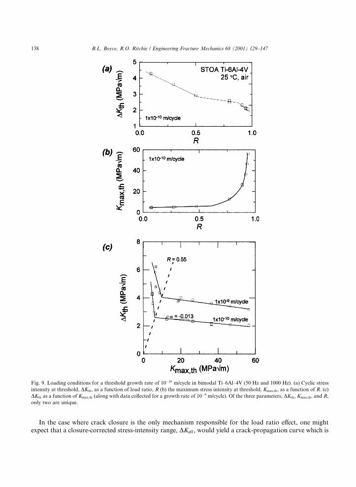
m/cycle (the latter representing the threshold DKth) for all eight loading conditions. These results arecompiled in Fig. 9a and b where the measured variation of the DKth and Kmax;th thresholds with positive Rare compared.
The role of load ratio at near-threshold levels is generally attributed to crack closure, which is typicallyassociated with the roughness-induced mechanism in titanium alloys [35±37]. In the current experiments,
Fig. 5. Fatigue crack growth behavior of bimodal Ti±6Al±4V at two load ratios (R � 0:1 and 0.8) and two frequencies (m � 50 and 1000
Hz) suggesting that there is negligible in¯uence of frequency in near-threshold growth behavior. Similar observations were made under
constant-Kmax loading conditions of Kmax � 36:5 and 56.5 MPap
m.
B.L. Boyce, R.O. Ritchie / Engineering Fracture Mechanics 68 (2001) 129±147 135

closure was approximated from the deviation from linearity in the unloading compliance curve. At low loadratios, R < 0:5, closure values were found to be approximately constant at Kcl � 2:0 MPa
pm, however, no
closure was detected at R > 0:5. This closure value was essentially identical for R � 0:1 and 0.3; moreover,the closure value did not change substantially as DK was shed towards threshold. The variation ofthresholds, DKth and Kmax;th, with load ratio (Fig. 9a and b) show an apparent transition at R � 0.5,consistent with the Schmidt and Paris [1] analysis (Eq. (1)) which would predict a transition at R � 0:3±0:5based on the measured closure value of 2 MPa
pm. Perhaps the most convincing representation of this
Fig. 6. Fatigue crack growth behavior of bimodal Ti±6Al±4V in the frequency range of 50±20,000 Hz indicating no obvious frequency
e�ect in the near-threshold regime. Data at 1700 Hz were collected using a magnetostrictive fatigue loading stage by Davidson [30].
Data at 20,000 Hz were collected using ultrasonic fatigue by Mayer and Stanzl-Tschegg [31]. Data at 30 Hz was collected by Hines and
L�utjering [32].
Fig. 7. E�ect of load ratio, R, on fatigue crack propagation under constant-R loading. As the load ratio is increased, the growth rates at
a given DK increase and the fatigue threshold decreases.
136 B.L. Boyce, R.O. Ritchie / Engineering Fracture Mechanics 68 (2001) 129±147

transition from a ``closure-a�ected'' to a ``closure-free'' threshold is shown in a plot of DKth versus Kmax;th inFig. 9c, which is simply a coordinate transformation of Fig. 9a and b. The distinct change in slope in Fig. 9cis surely associated with some change in governing mechanism, and is, in this case, coincident with theelimination of global crack closure.
Fig. 8. Fatigue crack propagation data collected under constant-Kmax conditions compared to R � 0:8 data (squares) collected under
constant-R conditions. As Kmax was increased such that the load ratios exceed R � 0:8, the value of the fatigue threshold continued to
decrease. This decrease in the fatigue threshold with increasing Kmax is observed in the apparent absence of crack closure, as detected by
back-face strain compliance.
Table 2
DK levels required for growth rates of 10ÿ9 and 10ÿ10 m/cycle
R Kmax (MPap
m) DK (MPap
m)
Growth rate, da=dN � 10ÿ9 m/cycle
0.1a 6.47±6.92 5.82±6.23
0.3 a 6.77±6.83 4.74±4.78
0.5 a 8.66±9.26 4.33±4.63
0.8 a 18.6±20.2 3.72±4.03
0.85 26.5 a 3.85
0.90 36.5 a �3.6
0.93 46.5 a �3.4
0.94 56.5 a �3.15
Growth rate, da=dN � 10ÿ10 m/cycle
0.1 a 4.72±4.78 4.25±4.30
0.3 a 5.16 3.61
0.5 a 5.86 2.93
0.8 a 12.5±13.1 2.50±2.61
0.91 26.5 a 2.33
0.94 36.5 a 2.11±2.15
0.955 46.5 a 2.09
0.954 56.5 a �2.04
a This value was held constant during the fatigue test.
B.L. Boyce, R.O. Ritchie / Engineering Fracture Mechanics 68 (2001) 129±147 137
In the case where crack closure is the only mechanism responsible for the load ratio e�ect, one mightexpect that a closure-corrected stress-intensity range, DKeff , would yield a crack-propagation curve which is
Fig. 9. Loading conditions for a threshold growth rate of 10ÿ10 m/cycle in bimodal Ti±6Al±4V (50 Hz and 1000 Hz). (a) Cyclic stress
intensity at threshold, DKth, as a function of load ratio, R (b) the maximum stress intensity at threshold, Kmax;th, as a function of R. (c)
DKth as a function of Kmax;th (along with data collected for a growth rate of 10ÿ9 m/cycle). Of the three parameters, DKth, Kmax;th, and R,
only two are unique.
138 B.L. Boyce, R.O. Ritchie / Engineering Fracture Mechanics 68 (2001) 129±147

una�ected by load ratio. Indeed, in the current study, DKeff does tend to normalize the low load ratio data(R < 0:5) onto a single curve (Fig. 10) (see also Ref. [5]). However, above R � 0:5 where (global) closurewas not experimentally detected, DKth values continue to decrease with increasing R. This is also apparentin the plot of DKth versus Kmax;th in Fig. 9c; in the region where threshold is Kmax-controlled, DKth is notinvariant and decreases approximately linearly with increasing Kmax. The slope of this decrease can bequanti®ed in terms of Eq. (2) as a � ÿ0:013, implying that an increase in the Kmax value of 10 MPa
pm is
associated with a 0.13 MPap
m decrease in DKth threshold.
4.3. Fractography and crack pro®les
Fractography (from scanning electron microscopy) and crack pro®les (from optical microscopy) cor-responding to the threshold growth rate of 10ÿ10 m/cycle at three load ratios, R � 0:1, 0.5, and 0.95, arecompared to the static overload condition in Fig. 11. The crack pro®les for the three load ratios show adecrease in crack-path tortuosity as R or Kmax is increased. Nevertheless, there are only minimal di�erencesin the fractography for the three di�erent load ratios, even though they span more than an order ofmagnitude in Kmax and two orders of magnitude in the plastic-zone size. There is a clear distinction,however, in the morphology of the fatigue surfaces compared to that of the overload fracture conditionwhere microvoid coalescence can be seen. Thus, it can be concluded that, even at R � 0:95 whereKmax � 57 MPa
pm �Kmax=KIc � 0:85�, there is no clear evidence of static fracture modes, in this case due to
microvoid coalescence, in the fractography of fatigue-crack growth in this alloy.
4.4. E�ect of internal hydrogen content
To study the e�ects of internal hydrogen content, several samples were heat treated in high vacuumat 700°C for 24 h thereby reducing the hydrogen content from an as-received value of �35 to �5 ppmwith no apparent microstructural changes. The low-hydrogen specimens were subsequently tested underfatigue loading conditions at constant-R � 0:5 and constant-Kmax � 28 MPa
pm. A comparison of the
near-threshold fatigue-crack growth behavior for the as-received and low internal hydrogen conditions is
Fig. 10. Considering only 50 Hz, constant-R data, raw growth data (open symbols) is compared to closure corrected data (closed
symbols) where closure is assessed by determining the e�ective stress intensity range: DKeff � Kmax ÿ Kcl.
B.L. Boyce, R.O. Ritchie / Engineering Fracture Mechanics 68 (2001) 129±147 139

Fig. 11. A comparison of fractography and crack pro®les under fatigue (observing a threshold growth rate �10ÿ10 m/cycle at three load
ratios, R � 0:1, 0.5, and 0.95) and static overload fracture condition. While microvoid coalescence is apparent in the overload fracture,
there is no clear evidence of this mode in the fatigue fractographs, even at R � 0:95 where Kmax � 57 MPap
m.
140 B.L. Boyce, R.O. Ritchie / Engineering Fracture Mechanics 68 (2001) 129±147

presented in Fig. 12, where it is apparent that there is little e�ect of hydrogen content (�5±35 ppm) in thisalloy. Most speci®cally, we see that the threshold was still a�ected by load ratios in excess of the ``closure-free'' transition (R > 0:5), in spite of the very low hydrogen content, and that the extent of this e�ectappears to be independent of hydrogen content over this range.
4.5. Sustained-load cracking
The results of sustained-load tests on the Ti±6Al±4V alloy at a constant applied stress intensity ofK � 36:5 MPa
pm, shown in Fig. 13, indicate approximately 80 lm of slow crack growth over the ®rst
1000 s following initiation from the fatigue pre-crack. The initial growth rate of �2� 10ÿ7 m/s was seento decay until crack arrest �<1�10ÿ11 m/cycle� within 1000 s. This transient behavior indicates that for
Fig. 12. The e�ect of internal hydrogen on near-threshold fatigue-crack propagation behavior in bimodal Ti±6Al±4V. Although the
hydrogen content was reduced by a factor of six or more, the DKth threshold is still signi®cantly a�ected by load ratios in excess of the
``closure-free'' transition, R � 0:5.
Fig. 13. Transient SLC observed at K � 36:5 MPap
m. The initial SLC growth-rate of 2� 10ÿ7 m/s is similar to the di�erence in the
fatigue-crack growth rates between R � 0:8 and Kmax � 36:5 MPap
m (Fig. 8).
B.L. Boyce, R.O. Ritchie / Engineering Fracture Mechanics 68 (2001) 129±147 141

near-threshold fatigue-crack growth to be a�ected by SLC, then the SLC mechanism must be ``restarted''by each fatigue cycle. Without ``restarting'' on each fatigue cycle, the SLC growth-rate would decay toarrest within the ®rst several minutes of a constant-Kmax fatigue test, and thus would have little or no e�ecton the value of the fatigue threshold.
5. Discussion
Crack closure is generally considered to be the primary reason for the e�ect of load ratio on the DKth
fatigue threshold in metallic materials. Indeed, at low load ratios such that R < Rc, the closure-basedanalysis describes threshold behavior reasonably well in most cases, including the data presented in thispaper. However, based on the closure argument, at load ratios where Kmin exceeds Kcl, (i.e. R > Rc) suchthat the in¯uence of (global) closure is minimized, the value of DKth would be expected to become inde-pendent of R. This is the generally anticipated behavior, however, in the current Ti±6Al±4V alloy, we haveobserved a progressive reduction in DKth from R � 0:5 (the ``closure-free'' condition) to R � 0:95; specif-ically, a � 1 MPa
pm decrease in DKth is found as Kmax increases from �6 MPa
pm (at R � 0:5) to 57
MPap
m (at R � 0:95). Furthermore, examples have been given (Table 1) of several other Ti-alloys that alsoexhibit a Kmax-sensitivity on the threshold at high load ratios �R > Rc�.
As noted previously, one possible explanation for this e�ect is the occurrence of SLC mechanisms duringfatigue-crack growth at high load ratios, where the high values of Kmax exceed some SLC threshold. Thisbeing the case, the measured fatigue-crack growth rates would result from contributions from both me-chanical fatigue cracking, �da=dN�fatigue, and that due to SLC �da=dt�SLC, as modeled using a processcompetition [38] or, as indicated in Eq. (5), a superposition [39] model: 4
dadN
����total
� dadN fatigue
���� � 1
mdadt
����SLC
: �5�
Support for this notion comes from the observation that the measured sustained-crack growth rate of�2� 10ÿ7 m/s at a sustained K of 36.5 MPa
pm corresponds to a growth rate per cycle at 1000 Hz of
�2� 10ÿ10 m/cycle, which is similar to the di�erence in the fatigue-growth rates at a given applied DK forR � 0:5 compared to 0.95. Two possible mechanisms for such SLC are described below:
(i) Stress-assisted hydride formation. Several independent studies in titanium alloys have concluded thatunder su�cient triaxial stress, internal hydrogen can precipitate as metal hydrides at a=b [40] or a=a [41]interfaces, or within a-grains [20] leading to brittle fracture of the hydrides. This phenomenon has been usedto explain both sustained-load cracking [20,21,42], where crack advance is observed under monotonic load,and accelerated fatigue-crack propagation at high load ratios [40,43].
(ii) Creep-assisted crack growth. Alternatively, since room-temperature creep can occur in titanium al-loys, it has been suggested that the role of hydrogen is to accelerate SLC by creep rather than throughhydride formation. Williams [44], for example, observed in Ti±6Al±4V that the threshold stress intensity forfailure by SLC, KSLC;th, increased with increasing hydrogen content, which is apparently counterintuitive tothe hydride formation mechanism. Furthermore, second-stage creep rate was observed to decrease sig-ni®cantly with increasing hydrogen content; at 95% of the yield strength, the creep rate decreased from120� 10ÿ6 %/h for 7 ppm H to 36� 10ÿ6 %/h for 60 ppm H. From these or similar observations, someauthors [44,45] have concluded that the role of hydrogen in sustained load crack stems from creep behaviorrather than the formation and failure of brittle hydrides.
4 One might argue that these models may be overly simplistic. Nevertheless, the rather basic notion that mechanical fatigue and SLC
should somehow act in concert is what is most important for the ensuing arguments.
142 B.L. Boyce, R.O. Ritchie / Engineering Fracture Mechanics 68 (2001) 129±147
Both of the aforementioned mechanisms suggest that the degree and extent of SLC is related to theinternal hydrogen content, although the exact role of hydrogen is still controversial. Nevertheless, if SLCgrowth was a signi®cant contribution to the observed fatigue crack-growth rates at high load ratios, onemay expect that the high-R behavior could be altered by changing the internal hydrogen content. Alter-natively, if hydrogen could (hypothetically) be entirely removed, the SLC mechanism should be entirelyeliminated, thereby yielding an invariant DKth threshold above the ``closure-free'' transition (R > 0:5),assuming that there are no additional mechanisms present. However, as illustrated in Fig. 12, a reduction inthe hydrogen content by more than a factor of six has essentially no e�ect on the fatigue thresholds in thisalloy. Moreover, the Kmax-sensitivity of the fatigue threshold at high load ratios remains essentially un-changed by the reduction in internal hydrogen.
Furthermore, setting the hydrogen observations aside, it seems unlikely that any SLC mechanism couldprovide a major contribution to fatigue in this alloy in light of the observed frequency independence(m � 50±1000 Hz) of fatigue-crack propagation that is observed at all load ratios (Fig. 6). Indeed, theobserved frequency independence indicates that if a chemically- or electrochemically-controlled mechanismwas related to the observed high-R load ratio e�ect, then the time-dependent processes must go to com-pletion within 1 ms (the time for one cycle at 1000 Hz).
Finally, any thermally-activated mechanism such as SLC, would be expected to manifest itself in thetemperature dependence of fatigue behavior. Thomas [46] has observed the SLC and fatigue-crack growthat three temperatures (ÿ30°C, 22°C and 140°C) in the same alloy and microstructure considered in thisstudy. He found that the extent of SLC transient growth decreased with increasing temperature, obeying anArrhenius relationship. At a sustained K of 60 MPa
pm, there was �500 lm of transient growth at ÿ30°C,
but only �45 lm of such growth at 140°C. Therefore, for SLC to be an important component of this alloyÕsfatigue behavior, one may expect the fatigue behavior to also be temperature-dependent. However, overthis same range in temperature, the fatigue behavior of this alloy remained invariant (observed at Kmax �60 MPa
pm).
While there is no doubt that SLC does occur in many titanium alloys, the observed lack of an e�ect offrequency, temperature, or hydrogen content on fatigue behavior strongly suggest that SLC does notcontribute signi®cantly to the Kmax-sensitive fatigue behavior at high load ratios in this particular alloy andmicrostructure. However, since the slopes, a, of DKth versus Kmax (for R > Rc) relationship (Eq. (1)) vary bya factor of roughly seven in titanium alloys and the current alloy/microstructure is at the shallow end ofthis range, it is conceivable that SLC does contribute to fatigue-crack growth behavior in certain other Tialloy microstructures, particularly those with higher internal hydrogen content. Indeed, there is someevidence in the literature that SLC may be an important component in the high-R fatigue behavior of othertitanium alloys. For example, Pao et al. [40] studied the e�ect of hydrogen content on the fatigue thresholdof a b titanium alloy at R � 0:9. As might be expected from a SLC contribution, they observed the fatiguethreshold to decrease with increasing hydrogen content. Speci®cally, when the hydrogen content waschanged from 40 to 1000 ppm, the threshold was reduced from 2.7 to 2.0 MPa
pm. This is in contrast to
the behavior currently observed in the a� b alloy in this study where an increase in hydrogen content from�5 to �35 ppm did not alter the threshold (Fig. 12), albeit these two observations were over di�erent rangesof hydrogen content.
As the observed lack of a signi®cant frequency or temperature e�ect on fatigue-crack propagation in thisalloy largely negates a major role of environmentally-assisted mechanisms in in¯uencing the Kmax de-pendence of the DKth threshold, other purely mechanical mechanisms may be considered, as describedbelow.
(i) Microscopic near-tip closure. During in situ studies in the scanning electron microscope of fatigue-crack propagation behavior in the same titanium alloy and microstructure at >1000 Hz, Davidson reportedthat he detected crack closure in the local region (within �10 lm) behind the crack tip, despite being at R
B.L. Boyce, R.O. Ritchie / Engineering Fracture Mechanics 68 (2001) 129±147 143

values of 0.8±0.9, i.e., well above the (global) ``closure-free'' load ratio, Rc [30]. While this near-tip (or local)closure is essentially undetectable by the macroscopic techniques such as unloading compliance, it couldnevertheless signi®cantly a�ect the e�ective stress intensity experienced at the crack tip. In this way, closurewould exist at all load ratios; however, the extent of the crack ¯ank over which it operates would be afunction of the load ratio (or more speci®cally, the minimum stress intensity). However, what detracts fromthis explanation is the marked transition at R � 0:5. As shown in Fig. 9c, there is a distinct transition fromDK-controlled to Kmax-controlled thresholds at R � 0:5. It is di�cult to reconcile this observation with anear-tip closure model, which would presumably manifest itself in a smooth transition from global- to near-tip closure as the extent of the closure wake grew smaller.
(ii) Static fracture modes. As Kmax values approach the point of instability, as characterized by KIc,additional static fracture modes, speci®cally cleavage, intergranular fracture or void coalescence, can oc-cur during fatigue-crack growth and lead to accelerated growth rates and a strong sensitivity to both loadratio and Kmax [9]. Such behavior is most often observed at lower load ratios and high growth rates, e.g.>10ÿ5 m/cycle, where the DK level is large such that Kmax ! KIc; in the present work at high load ra-tios where Kmax is held near KIc, static fracture modes could presumably occur even at near-thresholdgrowth rates. The occurrence of such static modes provides a very feasible explanation of the contin-ued Kmax-dependency of fatigue behavior at load ratios above the ``closure-free'' condition, Rc. How-ever, scanning electron micrographs of the fatigue fracture surfaces, shown in Fig. 11, reveal nosuch di�erences in the near-threshold fracture morphology at R � 0:5 and 0.95, despite the order ofmagnitude increase in Kmax (threshold Kmax values are 5.9 and 56.5 MPa
pm at R � 0:5 and 0.95, re-
spectively). Furthermore, the mechanism responsible for the downward trend in DKth with increasing R (orKmax) appears to active at even moderate ``closure-free'' load ratios (R � 0:8), where Kmax is much less thanKIc. Based on the lack of apparent static modes in the high-Kmax fractography, and the observed Kmax-sensitivity at even moderate load ratios, the static mode argument can be discounted as a potential ex-planation in this alloy.
(iii) Kmax-dependence on intrinsic near-threshold fatigue. As noted above, the mechanistic role of R orKmax on fatigue-crack growth is traditionally associated with crack closure and/or the occurrence of ad-ditional Kmax-controlled mechanisms, such as environmentally-assisted cracking or static modes. However,these mechanisms do not appear to be the controlling factors in the present alloy at R > Rc. Therefore, wemust consider whether the magnitude of Kmax can also a�ect the intrinsic mechanism of fatigue-crackgrowth, particularly since between R � 0:5 and 0.95 where the DKth threshold is reduced by �1 MPa
pm,
the maximum plane-strain plastic-zone size varies by some two orders of magnitude, from �2 to 200 lm, asKmax increases from �6 to 57 MPa
pm. Based on this signi®cant change in the local plasticity, it would seem
likely that there would be an e�ect on the fatigue-crack growth behavior and the value of the threshold.However, a majority of the existing mechanism-based intrinsic threshold models [47±52], which are mostoften based on the critical conditions for dislocation emission at the crack-tip, do not explicitly describe themechanistic nature of a Kmax-dependent component. The evidence presented here strongly implies that Kmax
does indeed in¯uence the threshold for fatigue-crack growth, independent of crack closure, presumably byits e�ect on intrinsic crack growth. The precise mechanism of this Kmax contribution, however, is presentlyunclear, although mechanisms associated with the spread of local plasticity would appear to be in¯uential.An understanding of this mechanism would greatly enhance our knowledge of the fundamental fatigueprocess.
6. Conclusions
A study has been made of the role of the maximum stress intensity (Kmax) and the load ratio (overthe range R� 0.1±0.95) in in¯uencing fatigue-crack propagation and speci®cally threshold behavior in a
144 B.L. Boyce, R.O. Ritchie / Engineering Fracture Mechanics 68 (2001) 129±147

Ti±6Al±4V alloy, tested over a range of loading frequencies (50±1000 Hz) and in room temperature air (22±32°C, 45% relative humidity). Based on this work, which was focused on an alloy with a bimodal (STOA)microstructure (�60 vol% primary-a, �40 vol% lamellar a� b), the following conclusions can be made:
1. Room temperature fatigue-crack growth (�10ÿ12±10ÿ6 m/cycle) and threshold DKth values were foundto be independent of loading frequency over the range 50±1000 Hz; companion studies at 20,000 Hz on thesame alloy/microstructure, together with previous results in the literature, suggest that such frequency-independent growth rate behavior at near-threshold levels extends over ®ve orders of magnitude from 0.1 to20,000 Hz.
2. The fatigue thresholds, DKth and Kmax;th, were found to vary signi®cantly with positive load ratio(R � 0:1±0:95). Consistent with the description of Schmidt and Paris, below a critical load ratio, Rc (�0.5),the Kmax;th threshold was seen to be independent of R, and the DKth decreased with increasing R. Bymeasuring (global) crack closure loads, using unloading compliance techniques, this behavior was found tobe consistent with the traditional explanation of load ratio e�ects on the fatigue threshold involving closure,with Rc de®ning the condition at which the closure stress intensity, Kcl � Kmin.
3. At load ratios larger than Rc, i.e., R� 0.5±0.95, where (global) crack closure could no longer bedetected, a di�erent dependence of the DKth threshold on load ratio was seen, with DKth ! 0 as R! 1. Suchbehavior is contrary to conventional explanations of the near-threshold load-ratio e�ect, which are basedon crack closure and imply that DKth is independent of load ratio for R > Rc. The decrease in DKth
threshold is approximately linear with increase in Kmax, decaying at a rate of ÿ0.013. A survey of literatureindicated that this e�ect was seen by several titanium alloys, with slopes varying between ÿ0.01 to ÿ0.07.
4. Explanations for this e�ect are suggested, based on the occurrence of (i) SLC due to internal hydrogen,(ii) static (Kmax-controlled) fracture modes, (iii) near-tip crack closure, and (iv) an e�ect of Kmax on theintrinsic mechanism of fatigue-crack growth. In the present alloy/microstructure, the e�ect could not beascribed to hydrogen-assisted SLC, as fatigue thresholds were una�ected by changes in hydrogen content,frequency, or temperature. Nor was the e�ect ascribed to the occurrence of static modes, as the morphologyof the near-threshold fatigue fracture surfaces was essentially unchanged between load ratios of 0.5±0.95.While near-tip closure may be a source for this e�ect, it seems most likely that the intrinsic fatigue-crackgrowth process is itself Kmax dependent. The Kmax-sensitivity should be considered in developing mecha-nistic intrinsic threshold models.
Acknowledgements
This work was supported by the US Air Force O�ce of Scienti®c Research under Grant No. F49620-96-1-0478 under the auspices of the Multidisciplinary University Research Initiative on High-Cycle Fatigue tothe University of California. Thanks are due to the Hertz Foundation for a graduate fellowship for B.L.B.,to Drs. H.R. Mayer and S.E. Stanzl-Tschegg for performing the ultrasonic fatigue experiments, and to Dr.J.P. Campbell and Z. Bell for experimental assistance.
References
[1] Schmidt RA, Paris PC. Threshold for fatigue crack propagation and the e�ects of load ratio and frequency. Progress in Flaw
Growth and Fracture Toughness Testing, ASTM STP 536, ASTM, Philadelphia, 1973. p. 79±94.
[2] Ritchie RO. Near-threshold fatigue crack propagation in ultra-high strength steel: in¯uence of load ratio and cyclic strength.
J Engng Mat Tech ASME Series H 1977;99:195±204.
B.L. Boyce, R.O. Ritchie / Engineering Fracture Mechanics 68 (2001) 129±147 145

[3] Liaw PK, Leax TR, Logsdon WA. Near-threshold fatigue crack growth behavior in metals. Acta Metall 1983;31:1581±7.
[4] Taylor D. A compendium of fatigue thresholds and growth rates. Engineering Materials Advisory Services Ltd., West Midlands,
UK, 1985.
[5] Dubey S, Soboyejo ABO, Soboyejo WO. An investigation of the e�ects of stress ratio and crack closure on the micromechanisms
of fatigue crack growth in Ti±6Al±4V. Acta Materialia 1997;45:2777±87.
[6] Ritchie RO, Boyce BL, Campbell JP, Roder O, Thompson AW, Milligan WW. Thresholds for high cycle fatigue in a turbine
engine Ti±6Al±4V alloy. Int J Fatigue 1999;22:621±31.
[7] Kardomateas GA, Carlson RL. Predicting the e�ects of load ratio on the fatigue crack growth rate and fatigue threshold. Fatigue
Fract Engng Mat Struct 1998;21:411±23.
[8] Chiang CR. Threshold stress intensity factor of fatigue cracks. Engng Fract Mech 1994;49:29±33.
[9] Ritchie RO, Knott JF. Mechanisms of fatigue crack growth in low alloy steel. Acta Metall 1973;21:639±48.
[10] Suresh S, Ritchie RO. On the in¯uence of environment on the load ratio dependence of fatigue threshold in pressure vessel steel.
Engng Fract Mech 1983;18:785±800.
[11] Lenets YN, Nicholas T. Load history dependence of fatigue crack growth thresholds for a Ti alloy. Engng Fract Mech
1998;60:187±203.
[12] D�oker H. Fatigue crack growth threshold: implications, determination and data evaluation. Int J Fatigue 1997;19:S145±149.
[13] Huthmann H, Gossmann O. Verband f�ur Materialforschung und ± pr�ufung. in 23. Vortragsveranstaltung des DVM-
Arbeitskreises Bruchvorg�ange, Deutscher, Berlin, 1981. p. 271±84.
[14] Bray GH, Donald JK. Separating the in¯uence of Kmax from closure-related stress ratio e�ects using the adjusted compliance ratio
technique. In: McClung RC, Newman Jr JC, editors. Advances in fatigue crack closure measurement and analysis: second volume.
ASTM STP 1343, American Society for Testing and Materials, Philadelphia, PA, 1997.
[15] Smith SW, Piascik RS. An indirect technique for determining closure free fatigue crack growth behavior. In: Newman JC, Piascik
RS, editors. Fatigue crack growth thresholds, endurance limits and design, ASTM STP 1372, American Society for Testing and
Materials, Philadelphia, 2000. p. 109±22.
[16] Marci G. A fatigue crack growth threshold. Engng Fract Mech 1992;41:367±85.
[17] Marci G. Non-propagation conditions (DKth) and fatigue crack propagation threshold (DKT). Fatigue Fract Engng Mater Struct
1994;17:891±907.
[18] Marci G. Comparison of fatigue crack propagation thresholds of two Ti tubrine-disk materials. Fatigue 1994;16:409±12.
[19] Marci G, Castro DE, Bachmann V. Fatigue crack propagation threshold. J Test Eval 1989;17:28±39.
[20] Moody NR, Costa JE. A review of microstructure e�ects on hydrogen-induced sustained load cracking in structural titanium
alloys. In: Kim Y-W, Bloyer RR, editors. Microstructure/property relationships in titanium aluminides and alloys. The Minerals,
Metals, and Materials Society, Warrendale, PA, 1991.
[21] Boyer RR, Spurr WF. Characteristics of sustained-load cracking and hydrogen e�ects in Ti±6Al±4V. Metall Trans A 1978;9A:
23±9.
[22] Marci G. Failure mode below 390 K with IMI 834. In: L�utjering G, Newack H, editors. Fatigue Õ96. Proceedings of the Sixth
International Fatigue Conference, Berlin, Germany, vol. 1, Pergamon, Oxford. 1996. p. 493±8.
[23] Marci G. Werksto�tech. Mat.-wiss 1997;28:51.
[24] Lang M, Hartman GA, Larsen JM. Investigation of an abnormality in fatigue crack growth curves ± the Marci e�ect. Scripta
Materialia 1998;38:1803±10.
[25] Eylon D. Summary of the available information on the processing of the Ti±6Al±4V HCF/LCF program plates. University of
Dayton Report, Dayton, OH, 1998.
[26] D�oker H, Bachmann V, Marci G. A comparison of di�erent methods of determination of the threshold for fatigue crack
propagation. In: B�acklund J, Blom AF, Beevers CJ, editors. Fatigue Thresholds, vol. 1. EMAS, Warley, UK, 1982. p. 45±58.
[27] Herman WA, Hertzberg RW, Jaccard R. A simpli®ed laboratory approach for the prediction of short crack behavior in
engineering structures. Fatigue Fract Engng Mater Struct 1988;11:303±20.
[28] Ritchie RO, Yu W. Short crack e�ects in fatigue: a consequence of crack tip shielding. In: Ritchie RO, Lankford J, editors. Short
Fatigue Cracks, TMS, Warrendale, PA, 1986. p. 167±89.
[29] Elber W. Fatigue crack closure under cyclic tension. Engng Fract Mech 1970;2:37±45.
[30] Davidson D. Damage mechanisms in high cycle fatigue. AFOSR Final Report, Project 06±8243. Southwest Research Institute,
San Antonio, TX, 1998.
[31] Mayer HR, Stanzl-Tschegg SE. Universit�at f�ur Bodenkultur, private communication, 1998.
[32] Hines JA, L�utjering G. Propagation of microcracks at stress amplitudes below the conventional fatigue limit in Ti±6Al±4V.
Fatigue Fract Engng Mater Struct 1999;22:657±65.
[33] Wanhill RJH. Environment and frequency e�ects during fatigue crack propagation in Ti±2.5 Cu (IMI 230) sheet at room
temperature. Corrosion-NACE 1974;30:28±35.
[34] Dawson DB, Pelloux RMN. Corrosion fatigue crack growth of titanium alloys in aqueous environments. Metall Trans
1974;5:723±31.
146 B.L. Boyce, R.O. Ritchie / Engineering Fracture Mechanics 68 (2001) 129±147

[35] Halliday MD, Beevers CJ. Some aspects of fatigue crack closure in two contrasting titanium alloys. J Test Eval 1981;9:
195±201.
[36] Ravichandran KS. Near threshold fatigue crack growth behavior of a titanium alloy: Ti±6Al±4V. Acta Metallurgica et Materialia
1991;39:401±10.
[37] Ogawa T, Tokaji K, Ohya K. The e�ect of microstructure and fracture surface roughness on fatigue crack propagation in a
Ti±6Al±4V alloy. Fatigue Fract Engng Mater Struct 1993;16:973±82.
[38] Austen IM, McIntyre P. Corrosion fatigue of high-strength steel in low-pressure hydrogen gas. Metal Sci 1979;13:420±8.
[39] Wei RP, Landes JD. Correlation between sustained-load and fatigue crack growth in high strength steels. Mater Res Standard
1970;9:25±46.
[40] Pao PS, Feng CR, Gill SJ. Hydrogen-assisted fatigue crack growth in beta-annealed Ti±6Al±4V. Scripta Materialia 1998;40:19±26.
[41] Peterson KA, Schwanebeck JC, Gerberich WW. In situ scanning Auger analysis of hydrogen-induced fracture in Ti±6Al±6V±2Sn.
Metall Trans A 1978;9A:1169±72.
[42] Sastry SM, Lederich RJ, Rath BB. Subcritical crack-growth under sustained load in Ti±6Al±6V±2Sn. Metall Trans A
1981;12A:83±94.
[43] Pao PS, OÕNeal JE. Hydrogen-enhanced fatigue crack growth in Ti±6242S. J Nucl Mater 1984;123:1587±91.
[44] Williams DN. E�ects of hydrogen in titanium alloys on subcritical crack growth under sustained load. Mater Sci Engng
1976;24:53±63.
[45] Freed AD, Sandor BI. Localised time-dependent and cycle dependent creep in notched plates. In: Gittus J, editor. Cavities and
cracks in creep and fatigue. Applied Science, UK, 1981. p. 89±108.
[46] Thomas JP. Subcritical crack growth of Ti±6Al±4V in the ripple-loading regime. In: Warren JR, Henderson J, editors. Proceedings
of the 4th National Turbine Engine High Cycle Fatigue Conference, Monterey, CA, Universal Technology Corp., Dayton, OH,
CD-Rom, session 2, 1999. p. 50±60.
[47] Weiss V, Lal DN. A note on the threshold condition for fatigue crack propagation. Metall Trans 1974;5:1946±9.
[48] Sandananda K, Shahinian PP. Prediction of threshold stress intensity for fatigue crack growth using a dislocation model. Int
J Fract 1977;13:585±94.
[49] Fine ME. Fatigue resistance of metals. Metall Trans 1980;11A:365±79.
[50] Liu HW, Liu D. Near threshold fatigue crack growth behavior. Scripta Metall 1982;16:595±600.
[51] Weertman J. Fatigue crack growth in ductile metals. In: Mura T, editor. Mechanics of fatigue, AMD-vol. 47. New York: ASME;
1982. p. 11±9.
[52] Davidson DL. A model for fatigue crack advance based on crack tip metallurgical and mechanics parameters. Acta Metall
1984;32:707±14.
B.L. Boyce, R.O. Ritchie / Engineering Fracture Mechanics 68 (2001) 129±147 147