
EECS 369: Introduction to Sensor...
51
EECS 369: Introduction to Sensor Networks Peter Scheuermann and Goce Trajcevski Week2: Overview of Communication and Networking – PartI 1
Transcript of EECS 369: Introduction to Sensor...

EECS 369: Introduction to Sensor Networks
Peter Scheuermann and Goce Trajcevski
Week2: Overview of Communication and Networking – PartI
1

Electromagnetic Signals – time domain
Strength of the signal (at space) = Function of time
Can also be expressed as a function of frequency
Signal consists of components of different frequencies
Analog signal - signal intensity varies in a smooth fashion over time
No breaks or discontinuities in the signal
Digital signal - signal intensity maintains a constant level for some
period of time and then changes to another constant level
Periodic signal - analog or digital signal pattern that repeats over time
s(t +T ) = s(t )
where T is the period of the signal
2

Electromagnetic Signals – time domain
Aperiodic signal - analog or digital signal pattern that doesn't repeat over time
Peak amplitude (A) - maximum value or strength of the signal over time (e.g., measured in volts)
Frequency (f )
Rate, in cycles per second, or Hertz (Hz) at which the signal repeats
Period (T ) - amount of time it takes for one repetition of the signal
T = 1/f
Phase () - measure of the relative position in time within a single
period of a signal
Wavelength () - distance occupied by a single cycle of the signal
Or, the distance between two points of corresponding phase of two
consecutive cycles 3

Electromagnetic Signals – time domain
(sine-waves)
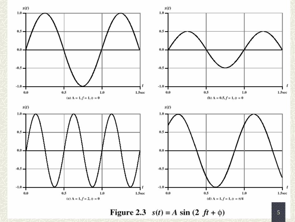
General sine wave
s(t ) = A sin(2ft + )
One can vary each of the three parameters in the definition
(a) A = 1, f = 1 Hz, = 0; thus T = 1s
(b) Reduced peak amplitude; A=0.5
(c) Increased frequency; f = 2, thus T = ½
(d) Phase shift; = /4 radians (45 degrees)
note: 2 radians = 360° = 1 period
When the horizontal axis is time, graphs show value of a signal at a
given point in space as a function of time
With the horizontal axis in space, graphs show value of a signal at a
given point in time as a function of distance
At a particular instant of time, the intensity of the signal varies as a
function of distance from the source
4
Sine Wave Parameters
5

Electromagnetic signals: frequency-domain
Fundamental frequency – the one of which all other frequency components of a signal are integer multiples of
Spectrum - range of frequencies that a signal contains
Absolute bandwidth - width of the spectrum of a signal
Effective bandwidth (or just bandwidth) - narrow band of frequencies that most of the signal’s energy is contained in
Any (including electromagnetic) signal can be shown to consist of a
collection of periodic analog signals (sine waves) at different
amplitudes, frequencies, and phases (Note: aperiodic signals have a
continuum of frequencies in their spectrum…)
Key mathematical tool: Fourier Transform
6

Electromagnetic signals – time vs. frequency
Adding different frequencies Approximating periodic signal With sine waves…
Illustration
of Fourier
Theorem
7

Electromagnetic signals – Fourier, spectra, bandwidth
Fundamental: f Spectrum: {f,3f,5f } Bandwidth: [5f – f ] = 4f
Fundamental: f Spectrum: {f,3f,5f,7f } Bandwidth: [7f – f ] = 6f
Fundamental: f Spectrum: {f,3f,5f,7f,9f,11f,… } Bandwidth: infinite…
NOTE: power = F (amplitude) => most of the useful “information” contained in a “narrow” bandwidth 8

Electromagnetic signals – Fourier, spectra,
bandwidth…
(Example:) Approximate the square wave of “0” and “1” with 3 sin-waves;
Assume that the main frequency is f = 1MHz;
Then:
- the bandwidth of the signal is 5f – f = 4f = 4MHz.
Now, for f = 1MHz, the period is t = 1/f = 10-6sec. To get a “feeling” about
the capacity of a channel transmitting such signal, assume that this represents
an alternating-bit-sequence: e.g., “1” or “0” occurs every half-period, which
is, a new bit every T/2 = 0.5s. Then:
- the speed of transmission (data rate) is 2x10⁶bps = 2Mbps, for a channel
with bandwidth of 4MHz with a fundamental frequency of 1MHz
Conclusions:
-Greater bandwidth => greater information-carrying capacity;
-A digital signal (even periodic!) will have infinite bandwidth;
-The system will limit the “useful” bandwidth (cost!)
-Any limit of the bandwidth will distort the signal…
9

Data, Signals, Communication…
Data - entities that convey meaning, or information
Signals - electric or electromagnetic representations of data
Transmission - communication of the data via the propagation and
processing of the corresponding signals
Analog
Video
Audio
Digital
Text
Integers
10

Analog vs. Digital Signals
A continuously varying electromagnetic wave that may be propagated over a variety of media, depending on frequency
Examples of media:
Copper wire media (twisted pair and coaxial cable)
Fiber optic cable
Atmosphere or space propagation
Analog signals can propagate analog and digital data
A sequence of voltage pulses that may be
transmitted over a copper wire medium
Generally cheaper than analog signaling
Less susceptible to noise interference
Suffer more from attenuation
Digital signals can propagate analog and
digital data Analog
D G T L
I I A
11

Analog Signaling
12

Digital Signaling
13

Choosing (Data, Signal) Combinations
Digital data, digital signal
Equipment for encoding is less expensive than digital-to-analog equipment
Analog data, digital signal
Conversion permits use of modern digital transmission and switching equipment
Digital data, analog signal
Some transmission media will only propagate analog signals
Examples include optical fiber and satellite
Analog data, analog signal
Analog data easily converted to analog signal
14

Analog Transmission
Transmit analog signals without regard to content
Attenuation limits length of transmission link
Cascaded amplifiers boost signal’s energy for longer distances but cause distortion
Analog data can tolerate distortion
Introduces errors in digital data
15

Digital Transmission
Concerned with the content of the signal
Attenuation endangers integrity of data
Digital Signal
Repeaters achieve greater distance
Repeaters recover the signal and retransmit
Analog signal carrying digital data
Retransmission device recovers the digital data from analog signal
Generates new, clean analog signal
16

Digital Channel Capacity
Impairments, such as noise, limit data rate that can be achieved
For digital data, to what extent do impairments limit data rate?
Channel Capacity – the maximum rate at which data can be transmitted over a given communication path, or channel, under given conditions
Data rate - rate at which data can be communicated (bps)
Bandwidth - the bandwidth of the transmitted signal as constrained by the transmitter and the nature of the transmission medium (Hertz)
17

Multi-level improvements: Nyquist Bandwidth
Noise - average level of noise over the communications path
Error rate - rate at which errors occur
Error = transmit 1 and receive 0; transmit 0 and receive 1
Recall the Example: for binary signals (two voltage levels)
C = 2B
Can be improved with multilevel signaling:
C = 2B log2 M
M = number of discrete signal or voltage levels
In the context of the previous example, all other things being equal, if we have 8 different voltage levels, than the capacity of the channel would increase to 6 Mbps…
18

Noise Impact: Signal-to-Noise Ratio
Ratio of the power in a signal to the power contained in the noise that’s present at a particular point in the transmission
Typically measured at a receiver
Signal-to-noise ratio (SNR, or S/N)
A high SNR means a high-quality signal, low number of required intermediate repeaters
SNR sets upper bound on achievable data rate, theoretically (Shannon):
power noise
power signallog10)( 10dB SNR
SNR1log2 BCIn practice, only much lower rates achieved:
- Formula assumes white noise (thermal noise), e.g.,
impulse noise is not accounted for
- Attenuation distortion or delay distortion not accounted
for
19

Realistic Channel (Nyquist + Shannon)
Example:
Assume: spectrum of a channel between 3 MHz and 4 MHz ;
SNRdB = 24 dB. Then:
Using Shannon’s formula
This can be achieved with:
different signaling levels
251SNR
SNRlog10dB 24SNR
MHz 1MHz 3MHz 4
10dB
B
Mbps88102511log10 6
2
6 C
16
log4
log102108
log2
2
2
66
2
M
M
M
MBC
20

Types of Transmission Media
Transmission Medium = Physical path between transmitter and receiver
Guided Media = Waves are guided along a solid medium
E.g., copper twisted pair, copper coaxial cable, optical fiber
Unguided Media = Provides means of transmission but does not guide electromagnetic signals
Usually referred to as wireless transmission
E.g., atmosphere, outer space
Transmission AND Reception done by an antenna (directional/omnidirectional)
21

General Frequency Ranges
802.11b;Bluetooth -> 2.4GHz 802.11a -> 5GHz
22

Multiplexing in Communication
Capacity of transmission medium usually exceeds capacity
required for transmission of a single signal
Multiplexing - carrying multiple signals on a single medium
More efficient use of transmission medium
23

Why Multiplexing…(FDM vs. TDM)
Cost per kbps of transmission facility declines with an increase in the
data rate
Cost of transmission and receiving equipment declines with increased
data rate
Most individual data communicating devices require relatively modest
data rate support
Frequency-division multiplexing (FDM)
Takes advantage of the fact that the useful bandwidth of the
medium exceeds the required bandwidth of a given signal
Time-division multiplexing (TDM)
Takes advantage of the fact that the achievable bit rate of the
medium exceeds the required data rate of a digital signal
24

FDM vs. TDM
25

Transmission – Signal Encoding Criteria
What determines how successful a receiver will be in interpreting an incoming signal?
Signal-to-noise ratio
Data rate
Bandwidth
An increase in data rate increases bit error rate
An increase in SNR decreases bit error rate
An increase in bandwidth allows an increase in data rate
Signal spectrum
With lack of high-
frequency components, less
bandwidth required
With no dc component, ac
coupling via transformer
possible
Transfer function of a
channel is worse near band
edges
Clocking
Ease of determining
beginning and end of each
bit position Signal interference and noise immunity
Performance in the presence of noise
Cost and complexity
The higher the signal rate to achieve a given data rate, the greater
the cost 26

Transmission – Digital-to-Analog Encoding
-Can have multiple
frequency shift key
(MFSK)
-Can combine ASK and
PSK to obtain QAM
(Quadrature Amplitude
modulation), enabling two
different signals to be
sent on one carrier frequency
27

Transmission – Analog-to-Analog Encoding
Carrier frequency needs
To be much higher, to
“minimize” the propagation
losses
NOTE: modulation
enables FDM…
28

Transmission – Analog-to-Digital Encoding
Based on the sampling theorem
Each analog sample is assigned a binary code
Analog samples are referred to as pulse amplitude modulation (PAM) samples
The digital signal consists of block of n bits, where each n-bit number is the amplitude of a PCM pulse
1. PCM (Pulse-Code Modulation)
29

Transmission – Analog-to-Digital Encoding
Analog input is
approximated by staircase
function
Moves up or down by
one quantization level
() at each sampling
interval
The bit stream
approximates derivative of
analog signal (rather than
amplitude)
1 is generated if
function goes up
0 otherwise
2. DM (Delta Modulation)
30

Transmission – Analog-to-Digital Encoding
Accuracy improved by increasing sampling rate
However, this increases the data rate
Advantage of DM over PCM is the simplicity of its implementation
Two important parameters
Size of step assigned to each binary digit ()
Sampling rate
Growth in popularity of digital techniques for sending analog data
Repeaters are used instead of amplifiers
No additive noise
TDM is used instead of FDM
No intermodulation noise
Conversion to digital signaling allows use of more efficient digital switching techniques
NOTE:
31

Transmission – Spread-Spectrum Encoding
On receiving end, digit
sequence is used to demodulate
the spread spectrum signal
Signal is fed into a channel
decoder to recover data
Input is fed into a channel
encoder
Produces analog signal
with narrow bandwidth
Signal is further modulated
using sequence of digits
Spreading code or
spreading sequence
Generated by
pseudonoise, or pseudo-
random number
generator
Effect of modulation is to
increase bandwidth of signal
to be transmitted
32
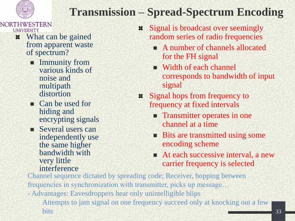
Transmission – Spread-Spectrum Encoding
What can be gained from apparent waste of spectrum?
Immunity from various kinds of noise and multipath distortion
Can be used for hiding and encrypting signals
Several users can independently use the same higher bandwidth with very little interference
Signal is broadcast over seemingly random series of radio frequencies
A number of channels allocated for the FH signal
Width of each channel corresponds to bandwidth of input signal
Signal hops from frequency to frequency at fixed intervals
Transmitter operates in one channel at a time
Bits are transmitted using some encoding scheme
At each successive interval, a new carrier frequency is selected
Channel sequence dictated by spreading code; Receiver, hopping between
frequencies in synchronization with transmitter, picks up message…
- Advantages: Eavesdroppers hear only unintelligible blips
Attempts to jam signal on one frequency succeed only at knocking out a few
bits 33

Transmission – Spread-Spectrum Encoding
34

Antennas and Signal Propagation
An antenna is an electrical conductor or system of conductors
Transmission - radiates electromagnetic energy into space
Reception - collects electromagnetic energy from space
In two-way communication, the same antenna can be used for transmission and reception
Radiation pattern
Graphical representation of radiation properties of an antenna
Depicted as two-dimensional cross section
Beam width (or half-power beam width)
Measure of directivity of antenna
Reception pattern
Receiving antenna’s equivalent to radiation pattern
35

Antennas and Signal Propagation
36
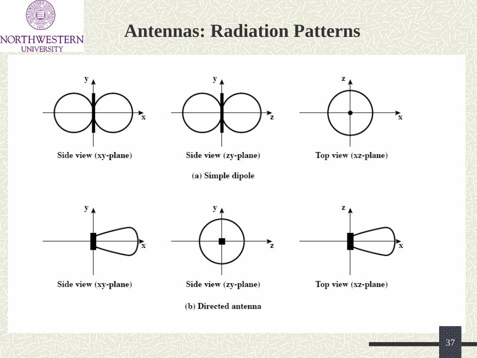
Antennas: Radiation Patterns
37

Antennas: Radiation Patterns
Most of the
antennas do NOT
operate equally-well
in all directions…
38

Antennas and Propagation
Relationship between antenna gain and effective area
G = antenna gain
Ae = effective area
f = carrier frequency
c = speed of light ( 3 ´ 108 m/s)
= carrier wavelength
Antenna gain
Power output, in
a particular
direction,
compared to that
produced in any
direction by a
perfect
omnidirectional
antenna (isotropic
antenna)
Effective area
Related to
physical size and
shape of antenna
2
2
2
44
c
AfAG ee
39

Antennas and Propagation
Ground-wave propagation:
Follows contour of the earth
Can Propagate considerable
distances
Frequencies up to 2 MHz
Example
AM radio
Sky-Wave Propagation
Signal reflected from ionized layer of
atmosphere back down to earth
Signal can travel a number of hops,
back and forth between ionosphere and
earth’s surface (1000’s of Km)
Reflection effect caused by refraction
Examples
Amateur radio
CB radio 40

Antennas and Propagation: Line-Of-Sight (LOS)
Transmitting and receiving antennas must be within line of sight
Satellite communication – signal above 30 MHz not reflected by ionosphere
Ground communication – antennas within effective line of site due to refraction
Refraction – bending of microwaves by the atmosphere
Velocity of electromagnetic wave is a function of the density of the medium
When wave changes medium, speed changes
Wave bends at the boundary between mediums
2157.3 hh
K = 4/3 41

Antennas: Reality-Check…
Strength of signal falls off with
distance over transmission medium
Attenuation factors for unguided
media:
Received signal must have
sufficient strength so that
circuitry in the receiver can
interpret the signal
Signal must maintain a level
sufficiently higher than noise
to be received without error
Attenuation is greater at higher
frequencies, causing distortion
Attenuation and attenuation distortion
Free space loss
Noise
Atmospheric absorption
Multipath
Refraction
Thermal noise
2
2
2
244
c
fdd
P
P
r
t
42
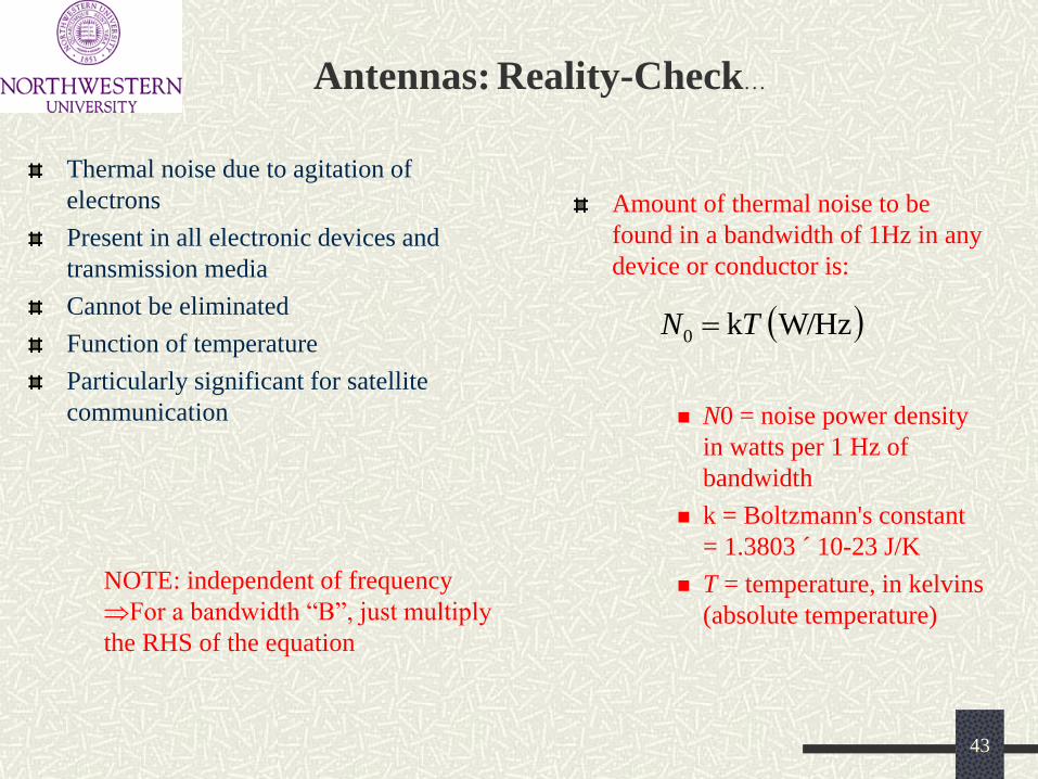
Antennas: Reality-Check…
Amount of thermal noise to be
found in a bandwidth of 1Hz in any
device or conductor is:
N0 = noise power density
in watts per 1 Hz of
bandwidth
k = Boltzmann's constant
= 1.3803 ´ 10-23 J/K
T = temperature, in kelvins
(absolute temperature)
Thermal noise due to agitation of
electrons
Present in all electronic devices and
transmission media
Cannot be eliminated
Function of temperature
Particularly significant for satellite
communication
W/Hz k0 TN
NOTE: independent of frequency
For a bandwidth “B”, just multiply
the RHS of the equation
43
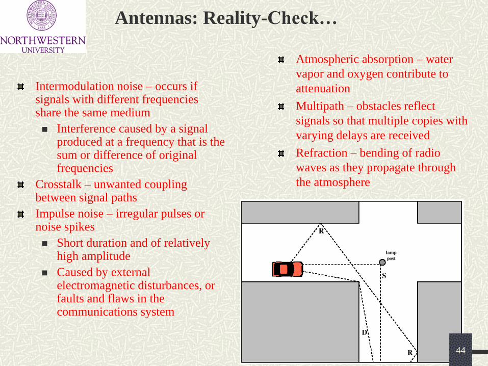
Antennas: Reality-Check…
Atmospheric absorption – water
vapor and oxygen contribute to
attenuation
Multipath – obstacles reflect
signals so that multiple copies with
varying delays are received
Refraction – bending of radio
waves as they propagate through
the atmosphere
Intermodulation noise – occurs if signals with different frequencies share the same medium
Interference caused by a signal produced at a frequency that is the sum or difference of original frequencies
Crosstalk – unwanted coupling between signal paths
Impulse noise – irregular pulses or noise spikes
Short duration and of relatively high amplitude
Caused by external electromagnetic disturbances, or faults and flaws in the communications system
44
Antennas: Reality-Check…
Multiple copies of a signal may arrive at different phases
If phases add destructively, the signal level relative to noise declines, making detection more difficult
Intersymbol interference (ISI)
One or more delayed copies of a pulse may arrive at the same time as the primary pulse for a subsequent bit
Dealing with “Reality”:
Transmitter adds error-correcting code to data block
Code is a function of the data bits
Receiver calculates error-correcting code from incoming data bits
If calculated code matches incoming code, no error occurred
If error-correcting codes don’t match, receiver attempts to determine bits in error and correct
…plus, some sophisticated signal-processing
algorithms to deal with intersymbol interference
45

Satellite Communication
Earth Stations –
antenna systems on
or near earth
Uplink – transmission
from an earth station
to a satellite
Downlink –
transmission from a
satellite to an earth
station
Transponder –
electronics in the
satellite that convert
uplink signals to
downlink signals
Coverage area
Global, regional,
national
Service type
Fixed service satellite
(FSS)
Broadcast service
satellite (BSS)
Mobile service satellite
(MSS)
General usage
Commercial, military,
amateur, experimental
Circular or elliptical orbit
Circular with center at earth’s center
Elliptical with one foci at earth’s center
Orbit around earth in different planes
Equatorial orbit above earth’s equator
Polar orbit passes over both poles
Other orbits referred to as inclined orbits
Altitude of satellites
Geostationary orbit (GEO)
Medium earth orbit (MEO)
Low earth orbit (LEO)
46

Satellites…
Advantages of the the GEO orbit
No problem with frequency changes
Tracking of the satellite is simplified
High coverage area
Disadvantages of the GEO orbit
Weak signal after traveling over 35,000 km
Polar regions are poorly served
Signal sending delay is substantial
Circular/slightly elliptical orbit under 2000 km
Orbit period ranges from 1.5 to 2 hours
Diameter of coverage is about 8000 km
Round-trip signal propagation delay less than
20 ms
Maximum satellite visible time up to 20 min
System must cope with large Doppler shifts
Atmospheric drag results in orbital
deterioration
- Little LEOs: Frequencies below 1 GHz ; 5MHz of
Bandwidth; Data rates up to 10 kbps…
Aimed at paging, tracking, and low-rate
messaging
-Big LEOs: Frequencies above 1 GHz; Support data
rates up to a few megabits per sec; Offer same
services as little LEOs in addition to
voice and positioning services
GEO: LEO:
47

Satellites…
Circular orbit at an altitude in the range of 5000 to 12,000 km
Orbit period of 6 hours
Diameter of coverage is 10,000 to 15,000 km
Round trip signal propagation delay less than 50 ms
Maximum satellite visible time is a few hours
MEO:
48

Satellites…
49
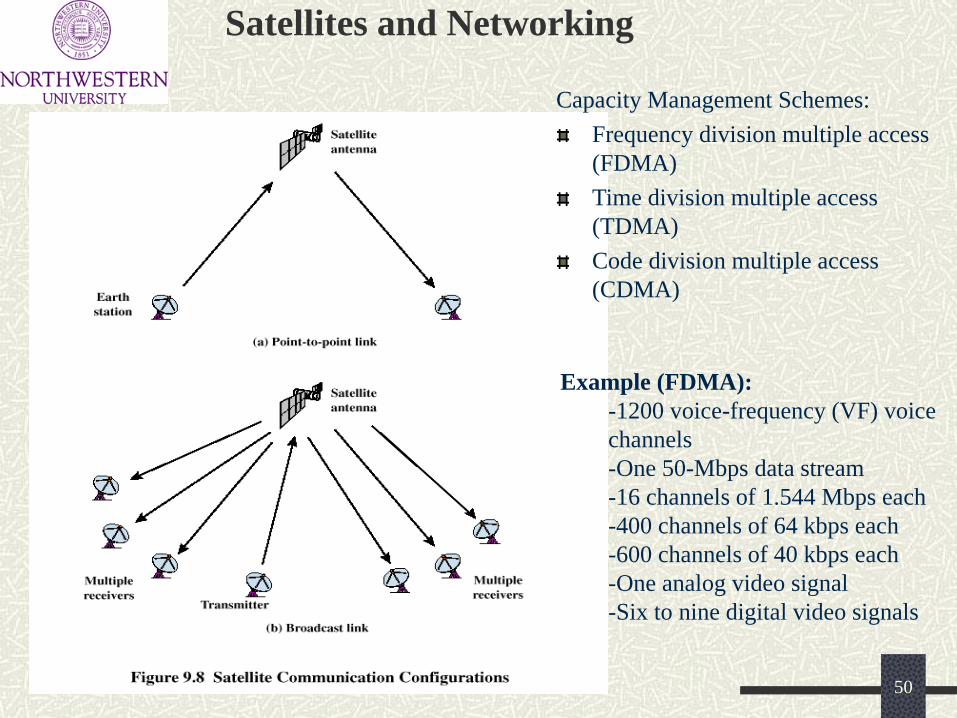
Satellites and Networking
Capacity Management Schemes:
Frequency division multiple access
(FDMA)
Time division multiple access
(TDMA)
Code division multiple access
(CDMA)
Example (FDMA):
-1200 voice-frequency (VF) voice
channels
-One 50-Mbps data stream
-16 channels of 1.544 Mbps each
-400 channels of 64 kbps each
-600 channels of 40 kbps each
-One analog video signal
-Six to nine digital video signals
50

Satellites and Networking…
51