EECE251 Circuit Analysis Set 2: Methods of Circuit...
19
1 1 SM EECE 251, Set 2 EECE251 Circuit Analysis Set 2: Methods of Circuit Analysis Shahriar Mirabbasi Department of Electrical and Computer Engineering University of British Columbia [email protected] 2 SM Reading Material • Chapter 3 of the textbook – Section 3.1: Nodal analysis – Section 3.2: Loop analysis (and mesh analysis which is a special case of loop analysis) EECE 251, Set 2
-
Upload
truongxuyen -
Category
Documents
-
view
240 -
download
4
Transcript of EECE251 Circuit Analysis Set 2: Methods of Circuit...
1
1SMEECE 251, Set 2
EECE251
Circuit Analysis
Set 2: Methods of Circuit Analysis
Shahriar MirabbasiDepartment of Electrical and Computer Engineering
University of British [email protected]
2SM
Reading Material
• Chapter 3 of the textbook
– Section 3.1: Nodal analysis
– Section 3.2: Loop analysis (and mesh analysis which is aspecial case of loop analysis)
EECE 251, Set 2
2
3SMEECE 251, Set 2
Methods of Circuit Analysis
• Two popular and powerful techniques for analyzing circuits are:
– Nodal analysis: a general procedure to find all the nodevoltages in a circuit. It is based on KCL and Ohm’s Law.
– Mesh analysis: another general approach to find meshcurrents which circulate around closed paths in the circuit. Itis based on KVL and Ohm’s Law.
• Yet there is another more general! and powerful! techniquewhich we call:
– Modified Nodal Analysis (MNA)
– Though more powerful it is not as popular of the first two(Almost all books don’t even have it!)
4SM
Definitions (Recall)
• These are standard textbook definitions (for node the definitionis slightly different from what we saw in slide set 1!)
– Node: A point of connection of two or more circuit elements.A node can be spread out with perfect conductors (wires)
– Branch: A portion of the circuit containing only a singleelement and the nodes at each end of the element (not thatwe are assuming that the elements have two terminals!)
– Loop: Any closed path through the circuit in which no nodeis encountered more than once.
EECE 251, Set 2
3
5SMEECE 251, Set 2
More Terminology
• Reference node or ground: a node that is assumed to have azero potential.
– If the reference node is not explicitly indicated on the circuitone can arbitrarily choose any node as the ground. We willsoon see how to choose a good ground node.
• Node voltage is the voltage difference/drop from a given nodeto the reference node.
6SMEECE 251, Set 2
Regular Nodal Analysis
• Steps to determine the node voltages for a circuit with nofloating voltage source:
1. Select a reference node. A floating voltage source is a voltagesource that neither of its terminals is connected to the referencenode.
2. Assign voltages to other nodes. These node voltages arereferenced to the reference node.
3. Write KCL for all unknown non-reference nodes. When possibleuse Ohm’s law to relate the branch currents to node voltages
4. Solve the resulting system of equations for unknown nodevoltages.
4
7SMEECE 251, Set 2
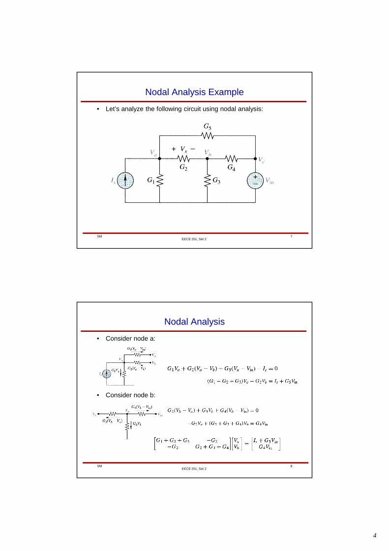
Nodal Analysis Example
• Let’s analyze the following circuit using nodal analysis:
8SMEECE 251, Set 2
Nodal Analysis
• Consider node a:
• Consider node b:
5
9SM
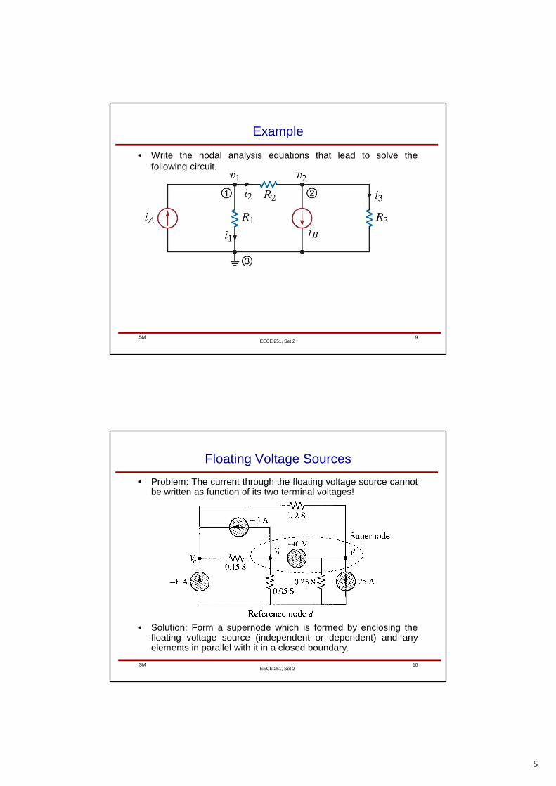
Example
• Write the nodal analysis equations that lead to solve thefollowing circuit.
EECE 251, Set 2
10SMEECE 251, Set 2
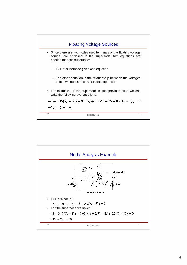
Floating Voltage Sources
• Problem: The current through the floating voltage source cannotbe written as function of its two terminal voltages!
• Solution: Form a supernode which is formed by enclosing thefloating voltage source (independent or dependent) and anyelements in parallel with it in a closed boundary.
6
11SMEECE 251, Set 2
Floating Voltage Sources
• Since there are two nodes (two terminals of the floating voltagesource) are enclosed in the supernode, two equations areneeded for each supernode:
– KCL at supernode gives one equation
– The other equation is the relationship between the voltagesof the two nodes enclosed in the supernode
• For example for the supernode in the previous slide we canwrite the following two equations:
12SMEECE 251, Set 2
Nodal Analysis Example
• KCL at Node a:
• For the supernode we have:
7
13SMEECE 251, Set 2
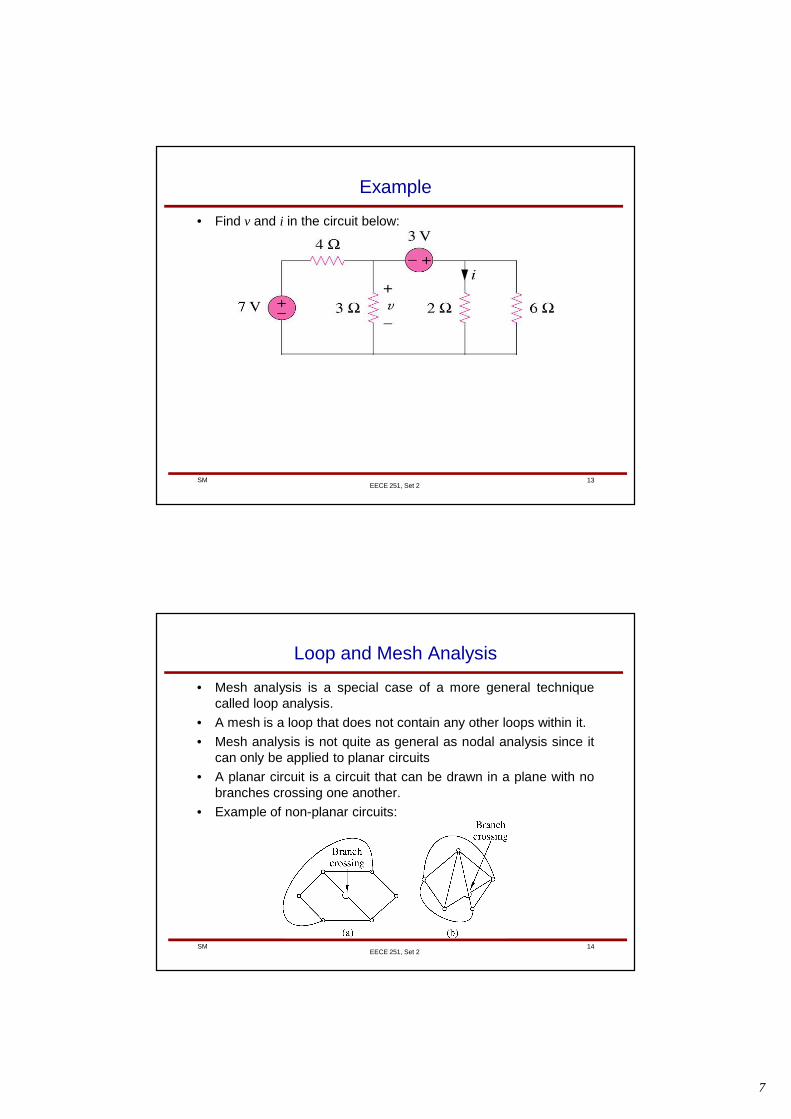
Example
• Find v and i in the circuit below:
14SMEECE 251, Set 2
Loop and Mesh Analysis
• Mesh analysis is a special case of a more general techniquecalled loop analysis.
• A mesh is a loop that does not contain any other loops within it.
• Mesh analysis is not quite as general as nodal analysis since itcan only be applied to planar circuits
• A planar circuit is a circuit that can be drawn in a plane with nobranches crossing one another.
• Example of non-planar circuits:
8
15SM
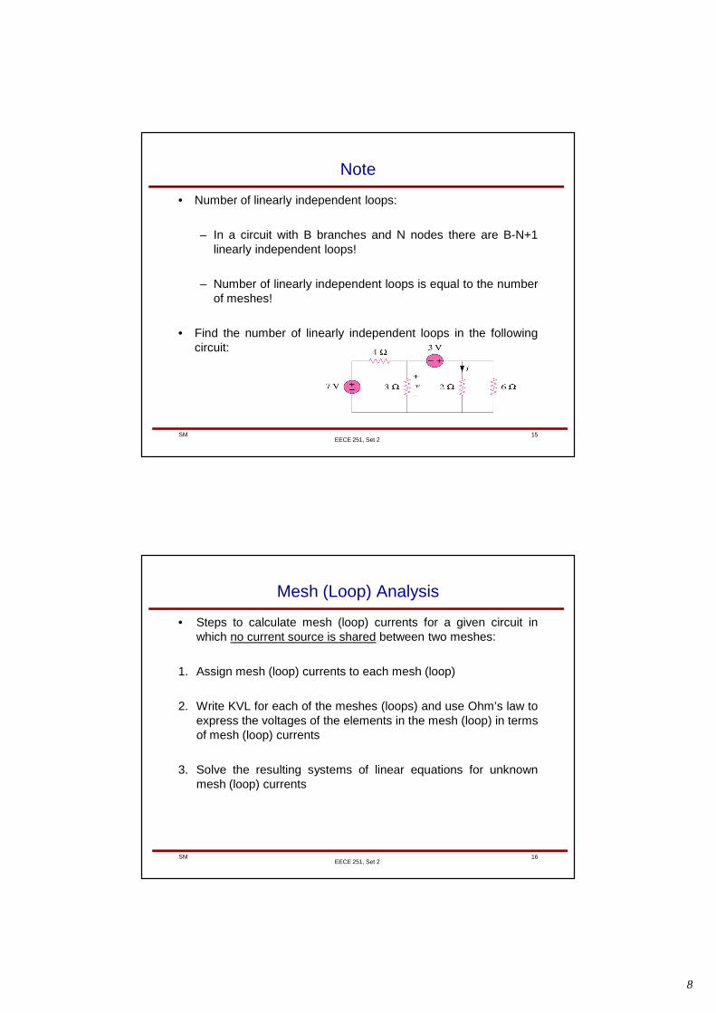
Note
• Number of linearly independent loops:
– In a circuit with B branches and N nodes there are B-N+1linearly independent loops!
– Number of linearly independent loops is equal to the numberof meshes!
• Find the number of linearly independent loops in the followingcircuit:
EECE 251, Set 2
16SMEECE 251, Set 2
Mesh (Loop) Analysis
• Steps to calculate mesh (loop) currents for a given circuit inwhich no current source is shared between two meshes:
1. Assign mesh (loop) currents to each mesh (loop)
2. Write KVL for each of the meshes (loops) and use Ohm’s law toexpress the voltages of the elements in the mesh (loop) in termsof mesh (loop) currents
3. Solve the resulting systems of linear equations for unknownmesh (loop) currents
9
17SMEECE 251, Set 2
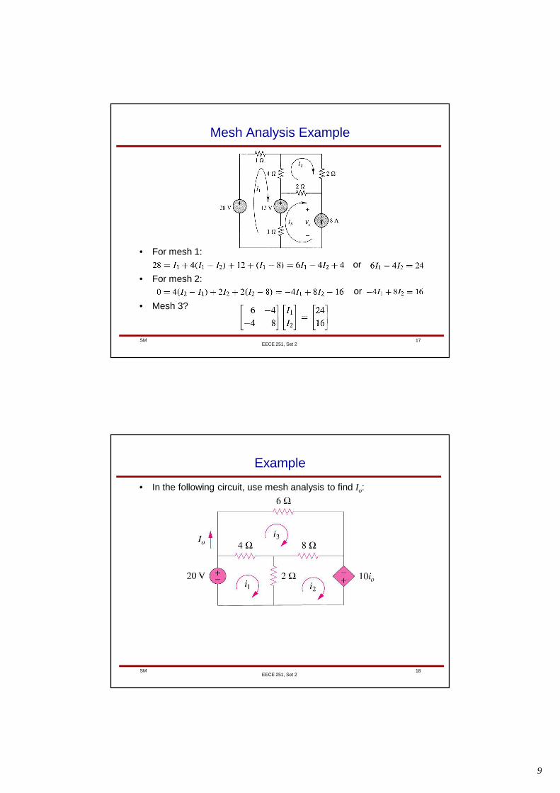
Mesh Analysis Example
• For mesh 1:
• For mesh 2:
• Mesh 3?
or
or
18SMEECE 251, Set 2
Example
• In the following circuit, use mesh analysis to find Io:
10
19SM
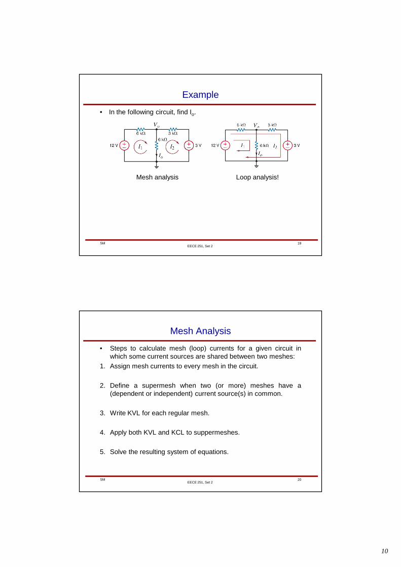
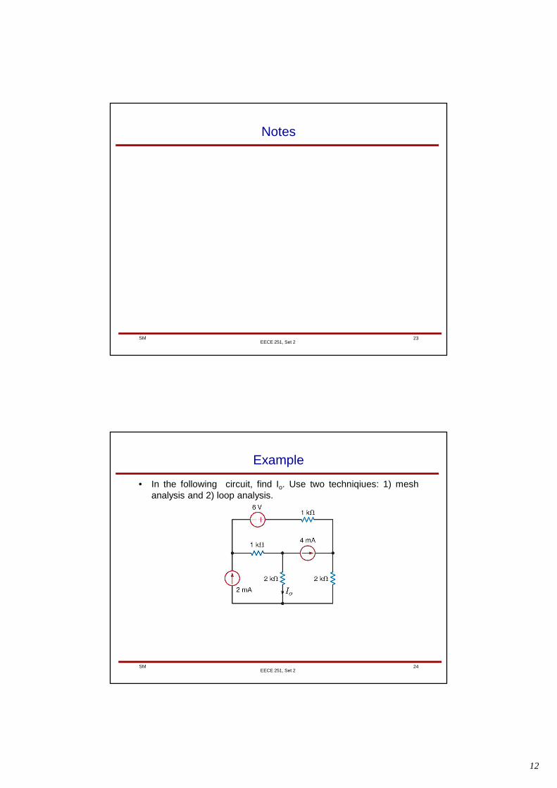
Example
• In the following circuit, find Io.
EECE 251, Set 2
Mesh analysis Loop analysis!
20SMEECE 251, Set 2
Mesh Analysis
• Steps to calculate mesh (loop) currents for a given circuit inwhich some current sources are shared between two meshes:
1. Assign mesh currents to every mesh in the circuit.
2. Define a supermesh when two (or more) meshes have a(dependent or independent) current source(s) in common.
3. Write KVL for each regular mesh.
4. Apply both KVL and KCL to suppermeshes.
5. Solve the resulting system of equations.
11
21SMEECE 251, Set 2
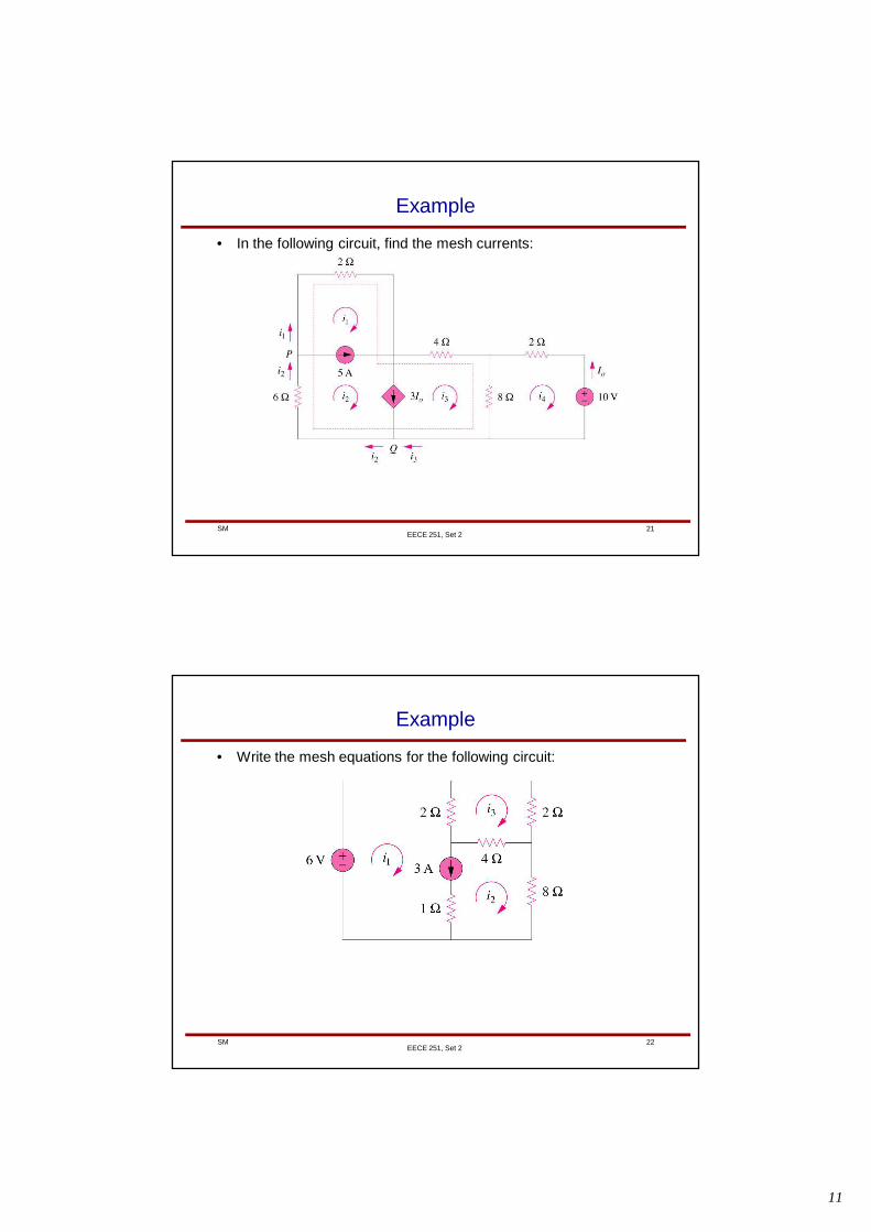
Example
• In the following circuit, find the mesh currents:
22SMEECE 251, Set 2
Example
• Write the mesh equations for the following circuit:
12
23SM
Notes
EECE 251, Set 2
24SM
Example
• In the following circuit, find Io. Use two techniqiues: 1) meshanalysis and 2) loop analysis.
EECE 251, Set 2
13
25SM
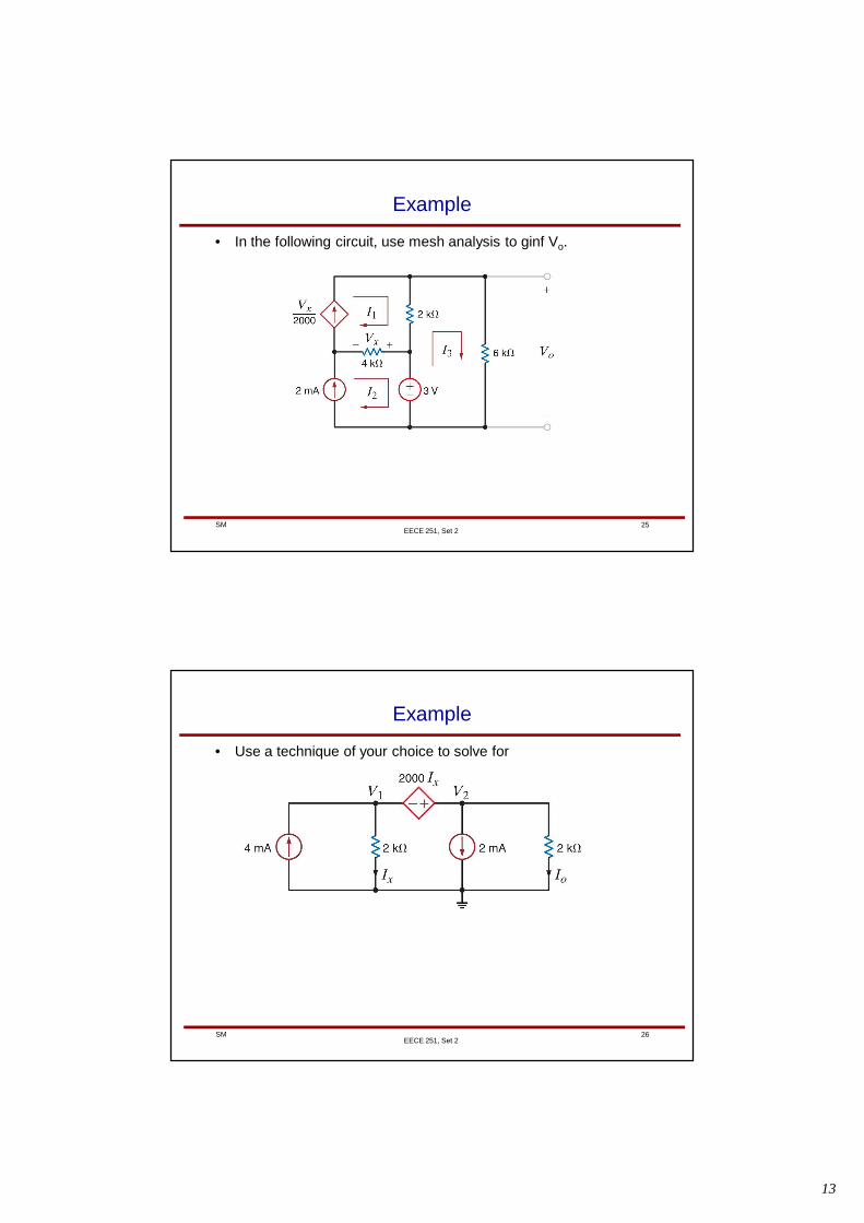
Example
• In the following circuit, use mesh analysis to ginf Vo.
EECE 251, Set 2
26SM
Example
• Use a technique of your choice to solve for
EECE 251, Set 2
14
27SM
Modified Nodal Analysis
• Recall: The following definitions of nodes (and branches)slightly differ from traditional textbook definitions! Please notethat almost all components that we deal with in this course aretwo-terminal components (resistors, sources, …)
• A “true node” (or node for short) is the point of connection ofthree or more circuit elements. (The node includes theinterconnection wires.)
• A “binary node” (or b-node for short) has only two componentsconnected to it.
• A “branch” is a collection of elements that are connectedbetween two “true nodes” that includes only those two truenodes (and does not include any other true nodes).
EECE 251, Set 2
28SM
Modified Nodal Analysis
• For modified nodal analysis (MNA) we need some moredefinitions!
• We identify four general types for branches as follows:
(we have seen these before, and here we are just formalizingthem by giving them proper names!):
R branch
RV branch
I branch (this also include any branch that consist of acurrent source in series with other components)
V branch (also known as evil branch!)
Let’s see if we can calculate the current of these branchesbased on the end-point node voltages!
EECE 251, Set 2
15
29SM
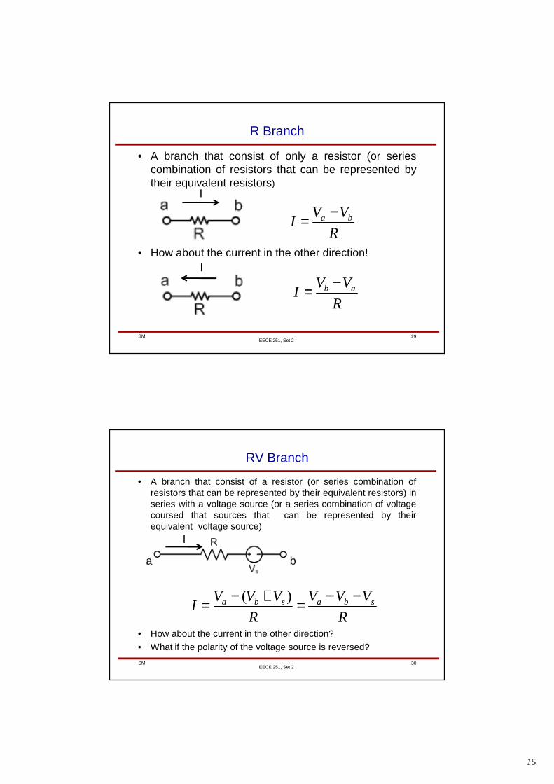
R Branch
• A branch that consist of only a resistor (or seriescombination of resistors that can be represented bytheir equivalent resistors)
• How about the current in the other direction!
EECE 251, Set 2
I
R
VVI ba −=
I
R
VVI ab −=
30SM
RV Branch
• A branch that consist of a resistor (or series combination ofresistors that can be represented by their equivalent resistors) inseries with a voltage source (or a series combination of voltagecoursed that sources that can be represented by theirequivalent voltage source)
• How about the current in the other direction?
• What if the polarity of the voltage source is reversed?
EECE 251, Set 2
I
a b
R
VVV
R
VVVI sbasba −−=+−= )(
16
31SM
Board Notes
EECE 251, Set 2
32SM
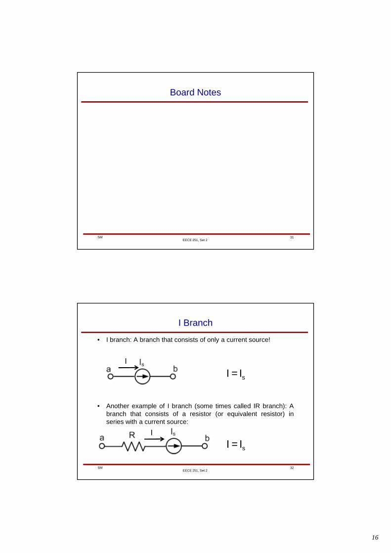
I Branch
• I branch: A branch that consists of only a current source!
• Another example of I branch (some times called IR branch): Abranch that consists of a resistor (or equivalent resistor) inseries with a current source:
EECE 251, Set 2
I
sII =
sII =I
17
33SM
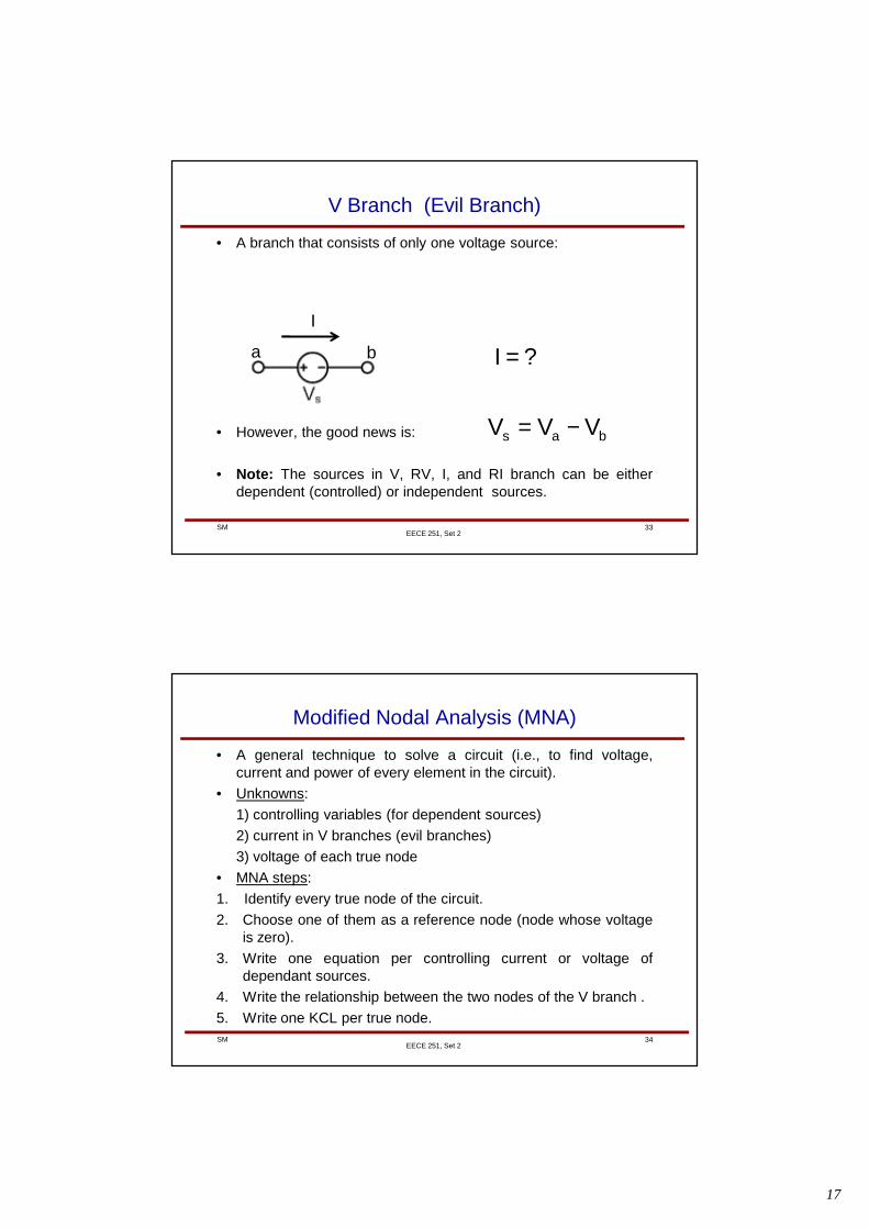
V Branch (Evil Branch)
• A branch that consists of only one voltage source:
• However, the good news is:
• Note: The sources in V, RV, I, and RI branch can be eitherdependent (controlled) or independent sources.
EECE 251, Set 2
I
a b ?I =
bas VVV −=
34SM
Modified Nodal Analysis (MNA)
• A general technique to solve a circuit (i.e., to find voltage,current and power of every element in the circuit).
• Unknowns:
1) controlling variables (for dependent sources)
2) current in V branches (evil branches)
3) voltage of each true node
• MNA steps:
1. Identify every true node of the circuit.
2. Choose one of them as a reference node (node whose voltageis zero).
3. Write one equation per controlling current or voltage ofdependant sources.
4. Write the relationship between the two nodes of the V branch .
5. Write one KCL per true node.
EECE 251, Set 2
18
35SM
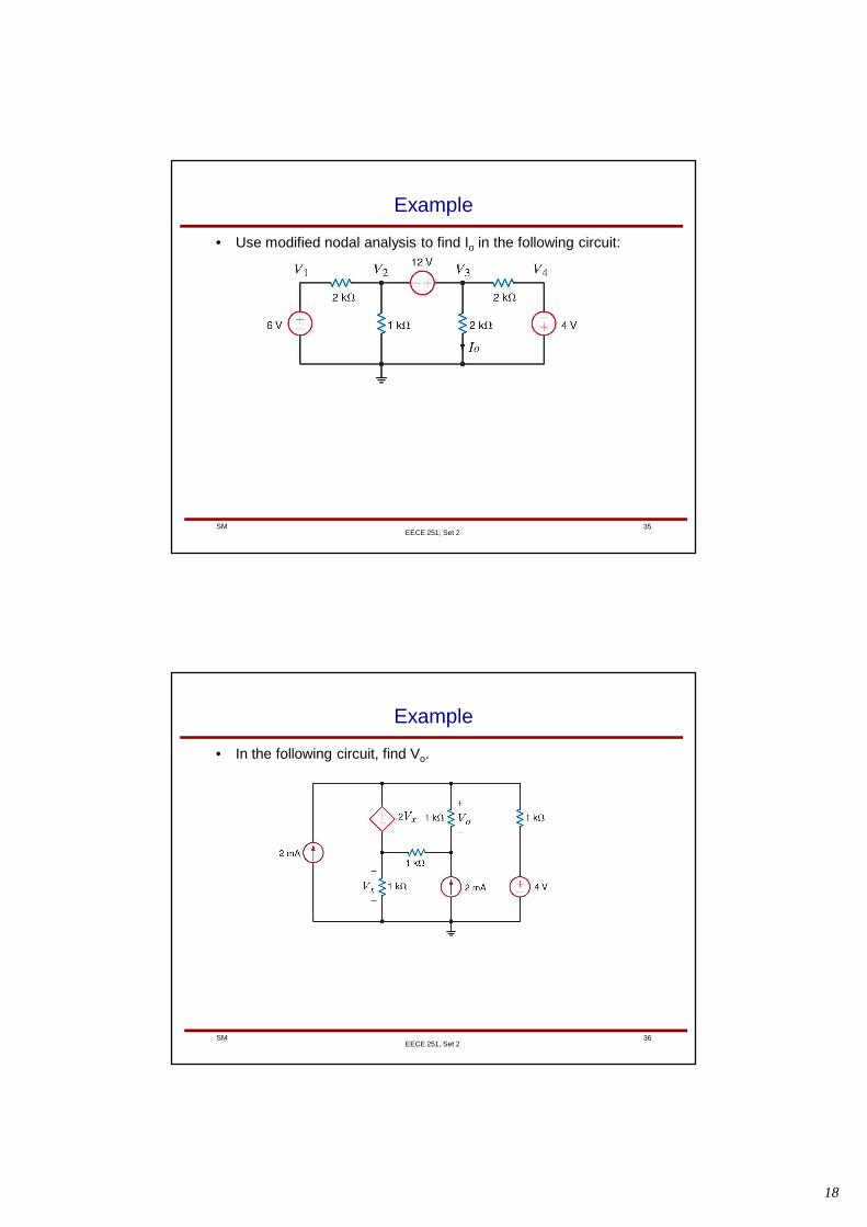
Example
• Use modified nodal analysis to find Io in the following circuit:
EECE 251, Set 2
36SM
Example
• In the following circuit, find Vo.
EECE 251, Set 2
19
37SM
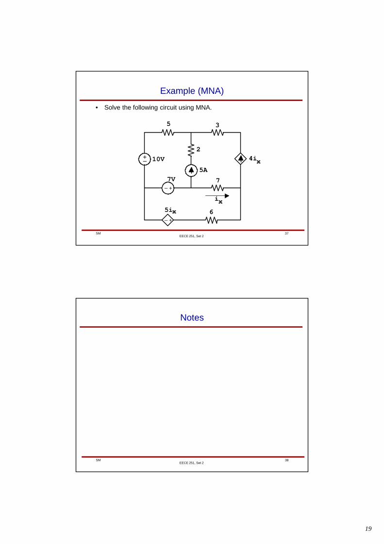
Example (MNA)
• Solve the following circuit using MNA.
EECE 251, Set 2
+_
+_
+_
5 3
2
7
6
10V
7V
5A
4i
5ix
x
ix
38SM
Notes
EECE 251, Set 2