EEBR308A Brake Lathes - Snap-on · EEBR308A Brake Lathes Installation Instructions Operating...
16
EEBR308A Brake Lathes Installation Instructions Operating Instructions Safety Instructions Maintenance Instructions READ these instructions before placing unit in service. KEEP these and other materials delivered with the unit in a binder near the machine for ease of reference by supervisors and operators.
Transcript of EEBR308A Brake Lathes - Snap-on · EEBR308A Brake Lathes Installation Instructions Operating...

EEBR308ABrake Lathes
Installation InstructionsOperating Instructions
Safety InstructionsMaintenance Instructions
READ these instructions before placing unit inservice. KEEP these and other materials deliveredwith the unit in a binder near the machine forease of reference by supervisors and operators.

2 • Snap-on
READ ALL INSTRUCTIONSWhen using your garage equipment, basic safety precau-
tions should always be followed, including the following:
1. Keep guards in place and in working order.
2. Remove adjusting keys and wrenches from the toolbefore turning it on. Make this a habit.
3. Keep work area clean and well lighted. Cluttered areasand benches invite accidents.
4.To reduce the risk of fire, do not operate equipment in thevicinity of open containers of flammable liquids (gasoline).
5. Adequate ventilation should be provided when workingon operating internal combustion engines.
6. Care must be taken as burns can occur from touchinghot parts.
7. Do not operate equipment with a damaged cord or if theequipment has been dropped or damaged—until it has beenexamined by a qualified serviceman.
8. If an extension cord is necessary, a cord with a currentrating equal to or more than that of the equipment should beused. Cords rated for less current than the equipment mayoverheat. Care should be taken to arrange the cord so that itwill not be tripped over or pulled.
9. To reduce the risk of electric shock, do not use on wetsurfaces or expose to rain.
10. Keep children away. All bystanders should be kept com-pletely away from the work area.
11. Make the workshop kid-proof. Use padlocks and mas-ter switches, and remove starter keys.
12. Don’t force a tool. It will do the job better and safer atthe rate for which it was designed.
13. Use the right tool. Don’t force a tool or an attachmentto do a job for which it was not designed.
14. Dress properly. Keep hair, loose clothing, neckties,shop rags, jewelry, fingers, and all parts of body away frommoving parts. Non-slip footwear is recommended.
15. ALWAYS WEAR SAFETY GLASSES. Everyday eye-glasses only have impact resistant lenses, they are NOTsafety glasses. Safety glasses, goggles, or a face shield willhelp protect the operator from injury. Use a face shield anddust mask during dusty operations.
16. Secure the work properly to the unit for setup and toolbit positioning. Do not attempt to hold a drum or rotor steadyon the arbor with your hands. Both hands must be free tooperate unit.
17. Don’t overreach. Keep proper footing and balance at alltimes when lathe is in operation or when working around theunit.
18. Maintain tools with care. Keep tools sharp and clean forbest and safest performance. Follow instructions for lubricat-ing and changing accessories.
19. Remove power from the unit and disconnect toolsbefore servicing and when changing accessories such asblades, bits, cutters, etc. Follow lock-out and tag-out proce-dures as required.
20. Avoid unintentional starting. Make sure the switch is inthe OFF (O) position before plugging the machine in or per-forming any maintenance or service work.
21. Use of improper accessories may cause risk of injury tooperator or bystanders. Use only as described in this manual.Use only manufacturer’s recommended attachments.
22. Never stand or lean on a lathe. Serious injury couldoccur if the lathe is tipped or if the cutting tool is unintention-ally contacted.
23. Check damaged parts carefully. Before further use ofthe lathe, a guard or other part that is damaged should becarefully checked. Immediately replace all damaged, missing,or non-functional parts. Check for alignment of moving parts,binding of moving parts, breakage of parts, mounting, and anyother conditions that may affect operation. Guards and otherparts that are damaged should be properly repaired orreplaced before lathe is used again.
24. Always feed the work into a blade or cutter and againstthe direction of rotation. Cutters and tool bits are designed tocut from the inside of a drum or rotor to the outer edge. Donot attempt to cut from the outside edge in to the center.
25. Never leave tools running unattended. Turn the poweroff. Don’t leave the tool until it comes to a complete stop.
26. Never use compressed air to blow the tool clean. Chipsand dust may be driven between machined parts and intobearings, causing undue wear. They may also contact personsin the area causing personal injury.
27. Operate the lathe in the proper environment. The latheincorporates parts such as snap switches and power recepta-cles which tend to produce arcs or sparks. Therefore, whenlocated in a garage,the unit should be in a room or enclosureprovided for the purpose, or should be at least 18” or moreabove the floor to minimize the risk of igniting fuel vapors.
Before operating the lathe, review the warning information on the lathe and the cautions, warnings and dangers in this man-ual. Also review the following general safety instructions. Failure to follow safety instructions could result in personal injury tooperator or bystanders and damage to the lathe or personal property.
IMPORTANT SAFETY INSTRUCTIONS
SAVE THESE INSTRUCTIONS

Snap-on • 3
Brake LathesTable of Contents
Important Safety Instructions . . . . . . . . . . .2
Safety Notices and Decals . . . . . . . . . . . . . .4
Warnings . . . . . . . . . . . . . . . . . . . . . . . . . . .4
Cautions and Dangers . . . . . . . . . . . . . . . . . . . . .4
Owner’s Responsibility . . . . . . . . . . . . . . . .5
Definitions of Hazard Levels . . . . . . . . . . . .5
Installation . . . . . . . . . . . . . . . . . . . . . . . . . .6
Electrical Wiring Requirements . . . . . . . . . . . . . .6Operating Specifications . . . . . . . . . . . . . . . . . . .6
Starting the Lathe . . . . . . . . . . . . . . . . . . . .7
Slide Travel . . . . . . . . . . . . . . . . . . . . . . . . . . . . .7Tool Bar Depth-of-Cut Micrometer Dial . . . . . . . .7Arbor Installation . . . . . . . . . . . . . . . . . . . . . . . . .7Rotor Mounting . . . . . . . . . . . . . . . . . . . . . . . . . .7Typical Rotor Mounting Configurations . . . . . . . .8
Reconditioning Disc Brake Rotors . . . . . . . .9
Set Up and Reconditioning Rotors . . . . . . . . .9-10
Reconditioning Brake Drums . . . . . . . . . . .11
Set Up and Machining . . . . . . . . . . . . . . . . . .11-12Typical Drum Mounting Configurations . . . . . . . .13
Maintenance and Service
Oiling . . . . . . . . . . . . . . . . . . . . . . . . . . . . . . . .14Cleaning . . . . . . . . . . . . . . . . . . . . . . . . . . . . . .14Care of Arbors and Adaptors . . . . . . . . . . . . . . .14Spindle V-belt Replacement . . . . . . . . . . . . . . . .14Spindle V-belt Adjustment . . . . . . . . . . . . . . . . .14Spindle Timing Belt Replacement . . . . . . . . . . . .15Spindle Timing Belt Adjustment . . . . . . . . . . . . .15
Tool Bar Adjustment . . . . . . . . . . . . . . . . . . . . .15Gib Adjustment . . . . . . . . . . . . . . . . . . . . . . . . .15

4 • Snap-on
Brake LathesSafety Notices and
DecalsFor your safety, and the safety of others, read and
understand all of the safety notices and decals includ-ed here and on the unit.
Read entire manual
before installing,
operating, or servic-
ing this equipment.
Proper maintenance
and inspection is
necessary for safe
operation.
Do not operate a
damaged lathe.
Failure to follow danger, warning, and cau-
tion instructions may lead to serious per-
sonal injury or death to operator or
bystander or damage to property. Do not
operate this machine until you read and
understand all the dangers, warnings and
cautions in this manual.
WarningsThis equipment incorporates parts such as snap
switches and power receptacles which tend to pro-duce arcs or sparks. Therefore, when located in a serv-ice facility, the unit should be in a room or enclosureprovided for the purpose, or should be at least 18” ormore above floor to minimize the risk of igniting fuelvapors.
Cautions and Dangers1. Eye and face protection requirements:
“Protective eye and face equipment is requiredto be used where there is a reasonableprobability of injury that can be prevented by useof such equipment.” OSHA 1910.133 (a).
Protective goggles, safety glasses, or a faceshield must be provided by the purchaser/userand worn by the operator of the equipment.Make sure all eye and face safety precautions arefollowed by the operator(s). Keep bystanders outof the area.
2. Do not remove any safety equipment, beltguards, or shortcut controls or operations.
3. Make sure drums and rotors are properly andsquarely mounted before starting lathe, and thatall parts are secure.
4. Do not wear loose clothing, jewelry, or gloveswhen operating or working around a lathe.
5. Do not overload the lathe. Read and understandthe lathe specifications. Overloading is poormachine tool practice, shortens the life of thelathe, and could cause a failure resulting inpersonal injury.
WARNINGFor Your Own Safety Read Instruction
Manual Before Operating Lathe• Wear eye protection.• Do not wear gloves, necktie, or loose clothing.• Tighten all locks before operating.• Rotate workpiece before installing on faceplate.• Risk of injury due to accidential starting.• Do not use in an area where children may be present.
WARNING
941134

Snap-on • 5
Brake LathesOwner’s ResponsibilityTo maintain machine and user safety, the responsi-
bility of the owner is to read and follow these instruc-tions:
• Follow all installation instructions.
• Make sure installation conforms to all applicableLocal, State, and Federal Codes, Rules, andRegulations; such as State and Federal OSHARegulations and Electrical Codes.
• Carefully check the unit for correct initial function.
• Read and follow the safety instructions. Keepthem readily available for machine operators.
• Make certain all operators are properly trained,know how to safely and correctly operate theunit, and are properly supervised.
• Allow unit operation only with all parts in placeand operating safely.
• Carefully inspect the unit on a regular basis andperform all maintenance as required.
• Service and maintain the unit only withauthorized or approved replacement parts.
• Keep all instructions permanently with the unitand all decals/labels/notices on the unit clean andvisible.
• Do not override safety features.
Definitions of HazardLevels
Identify the hazard levels used in this manual withthe following definitions and signal words:
DANGERWatch for this symbol:
It Means: Immediate hazards, which will result insevere personal injury or death.
WARNINGWatch for this symbol:
It Means: Hazards or unsafe practices, which couldresult in severe personal injury or death.
CAUTIONWatch for this symbol:
It Means: Hazards or unsafe practices, which mayresult in minor personal injury or product or propertydamage.
Watch for this symbol! It means BE ALERT! Yoursafety, or the safety of others, is involved!
CAUTION
WARNING
DANGER

6 • Snap-on
Brake LathesInstallation
1. Cut the straps securing the lathe to the shippingpallet. Place the lathe on the bench.
2. Position the lathe over the four (4) holes indicatedin Fig. 1. Use the four (4) pilot bolts and washers pro-vided to fasten the lathe to the bench. Wrench tightenthe bolts.
3. Before plugging the lathe in, be sure the on/offtoggle switch above the drum slide handwheel is inthe OFF position.
READ THE OILING INSTRUCTIONS BEFORE OPER-ATING THE LATHE.
Figure 1
Electrical Wiring RequirementsThe lathe should be electrically grounded to protect
the operator from shock. The lathe is equipped with anapproved 3-conductor cord and a 3-prong groundingtype plug to fit the proper grounding type receptacle.If your lathe is for use on 115 volts, it has a plug andoutlet as illustrated in Fig. 2. Use only 3-wire exten-sion cords which have 3-prong grounding type plugsand 3-pole receptacles which accept the lathe’s plug.230 volt lathes use a plug and outlet like those illus-trated in Fig. 3.
Replace or repair damaged or worn cords immedi-ately.
Figures 2 & 3
Operating SpecificationsOverall Lathe Height . . . . . . . . . .14.25 in. (362 mm)
Spindle to Floor . . . . . . . . . . . . .39.25 in. (997 mm)(when mounted on bench)
Spindle Speed . . . . . . . . . . . . . . . . . . . . . .125 RPM
Rotor Slide Feed Rate . . . ..0032 inch per revolution(.0813 mm/rev.)
Drum Slide Feed Rate . . . ..0048 inch per revolution(.1219 mm/rev.)
Micrometer Graduations . . . . . ..002 in. (.0508 mm)
Max. Brake Rotor Diameter . . . . . .15.75 in. (40 cm)
Max. Brake Rotor Thickness . . . . .1.75 in. (4.45 cm)
Min. Brake Drum Diameter . . . . . . .6 in. (15.25 cm)
Max. Brake Drum Diameter . . . . . .24 in. (60.96 cm)
Max. Drum Depth . . . . . . . . . . . . . .7 in. (17.78 cm)
Max. Load, 1 in. Arbor . . . . . . . . .100 lbs. (4536 Kg)
Max. Load, 1-7/8 in. Arbor . . . . . .200 lbs. (90.72 Kg)
Spindle Motor . . . . . . . . . . . . . . . . . . . . . . . . .1 HP
Electrical Requirements . . . . .115 VAC. 60 Hz, 1 Ph,fused at 15 A
Lathe Weight . . . . . . . . . . . . . . . . .312 lbs. (141 Kg)(lathe only)
Floor Space . . . . . . . . .34.75 in. wide x 48 in. deep(822.65 mm x 1,219.22 mm)
(when mounted on bench)
Snap-on • 7
Starting the LatheThe toggle switch, above the drum slide handwheel,
turns the lathe ON and OFF.
Slide TravelThe drive motors of the slides are on when the tog-
gle switch is in the ON position. The slides will movethrough their full travel with a few turns of the hand-wheels when the slide engagement knobs are loose.When the slide engagement knobs are tightened, theslides will feed in an outward direction until the slideengagement knobs are loosened or the slides reachthe end of their travel.
Note: To prevent undue wear, DO NOT allow thelathe to run for extended periods with the slides at theend of their travel and the feeds engaged. The slideengagement knobs are tight. See how-to-use detailsunder reconditioning disc brake rotors and recondi-tioning brake drums.
Tool Bar Depth-of-Cut Micrometer DialThe tool bar depth-of-cut micrometer dial is cali-
brated with both inch and metric scales. The depth-of-cut dial indicates the amount of material being cutfrom one side of a drum or rotor.
Inch Scale:
A cut of .002" (one micrometer division) from an 8"drum will result in a refinished diameter of 8.004"
Metric Scale:
A cut of .05 mm (one micrometer division) from a209 mm drum will result in a refinished diameter of209.1 mm.
Arbor InstallationThe 1" arbor shipped with the lathe has been care-
fully matched to the spindle of the lathe during finalassembly and testing. Witness marks have beenetched onto the arbor and spindle for repeatable, pre-cise alignment.
The witness marks should be carefully aligned wheninstalling the arbor. A true running arbor is essential toprofessional quality brake drum and rotor recondition-ing.
The drawbar, which can be tightened or loosened atthe rear of the spindle, pulls the hardened and groundtaper of the arbor into the ground taper seat of thespindle.
Rotor MountingReview the descriptions of typical rotor mounting
configurations. The same directions apply whenmounting a brake rotor. Hubbed rotors are mountedon adapters that fit into the bearing races. Hublessrotors use a cone in the center hole and a hublessadapter on each side of the rotor. Spacers are used tofill out the arbor shaft so that the arbor nut can betightened. The setups illustrated in Figure 4 are typicalof the many mounting configurations necessary tomeet the requirements of brake rotor reconditioning.The adapters, cones, and spacers supplied with thelathe will allow reconditioning of the majority of therotors found on current production vehicles. Optionaladapters, cones, and spacers are available to meetspecial needs.
Note: Adapters may also be used as spacers to fillout the arbor shaft if care is taken to prevent damageto their machined surfaces.
The patented self-aligning spacer prevents diagonalthrust on the adapters. The self-aligning spacer shouldalways be used adjacent to the arbor nut.
Brake Lathes

8 • Snap-on
Brake Lathes
�
�
�
�
�
�
��
��
��
�
�
��
�
� - 1" Arbor� - Arbor Nut� - Self-Aligning Spacer� - Spacer� - Small Double Taper Adapter� - Large Double Taper Adapter� - Adapter, Used as Spacer
Typical Rotor Mounting ConfigurationsNote: Refer to instructions in adapter kit for mounting
Hubless drums and rotors.
Figure 4

Snap-on • 9
Brake LathesReconditioning Disc
Brake Rotors1. Inspect the rotor carefully for scoring, rust ridges
(at the inner and outer circumference of the rotor), andhard spots. Any excessive wear or deformity shouldbe noted and, if not within acceptable limits, the rotorshould be replaced.
2. Use a micrometer to check the thickness of therotor (figure 5) at no less than 3 points around the cir-cumference about 1" (2.54 mm) in from the outerdiameter.
If the rotor thickness varies between readings, itshould be reconditioned. However, if the thickness isless than the minimum established by the manufac-turer, or if it will be less after reconditioning, the rotorshould be replaced.
Note: Most often the DISCARD thickness dimensionis cast or stampedinto the rotor, not theminimum machine-tothickness.
Figure 5
Set Up and Reconditioning Rotors1. Install a silencer band on the mounted rotor.
Stretch the band around the rotor and hook the metalloop over a lead weight.
2. Center the twin cutter to the rotor. Loosen thestud nut and adjust the twin cutter so that the rotor iscentered between the tool bits. Tighten the stud nutfirmly.
3. Install the safety shield as shown. Review thecautions and dangers section and the general safetyinformation at the beginning of this manual. The safetyshield is easily screwed onto the twin cutter in thethreaded mounting hole provided.
Always wear safety glasses or a face shield.
Cutting or grinding on an exposed surface
such as a rotor will produce flying chips
and debris.
4. Turn the rotor slide handwheel clockwise to posi-tion the rotor slide about 1/2" away from therotor/silencer band (vented rotors), or 1/2" away fromthe edge of the rotor (non-vented rotors).
5. Make sure that the tool bits clear the rotor sur-faces and the silencer band. Give the rotor a full turnby hand and watch for clearance all the way around.
6. Turn the lathe ON.
7. Turn each tool bit control (the outer knurledknobs, clockwise until the tool bits just contact therotor surfaces.
Figure 6
8. When the tool bits make contact, rotate each ofthe inner depth-of-cut collars to zero and back the toolbits away from the rotor.
From this point on, all tool adjustments will be madewith the tool bit controls. Then inner depth-of-cut col-lars will be the reference and should not be moved.
Figure 7
9. Turn the rotor slide handwheel until the tool bitsare at mid-point of the rotor face.
10. Turn the left-hand tool bit control until the toolbit contacts the rotor surface and makes a scratch cut.After the cut is made, back the tool bits off and turnthe lathe OFF.
The scratch will usually appear as an incomplete cir-cle. This is caused by runout or wobble due to rotorcondition, or by the way the rotor is mounted on thearbor.
WARNING
Inner depth-of-cut collars
Tool bit controls
Hold knob with onehand – turn collar
Each increment =0.002” english,0.05 mm metric
First scratch cut
Micrometer
10 • Snap-on
Brake Lathes
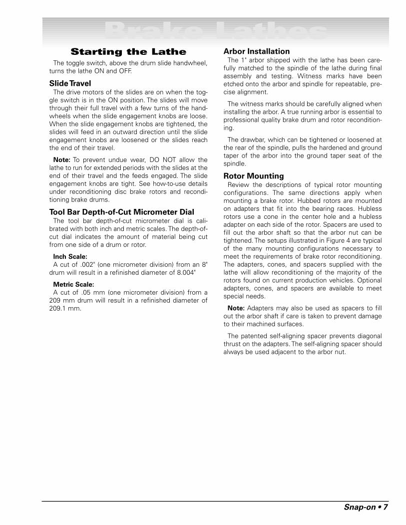
Figures 8 & 9
11. Check rotor mounting by loosening the arbornut and turning the rotor 180° by hand on the arbor.Make sure the inside adapter does not rotate alongwith the rotor. Then retighten the arbor nut, turn therotor slide handwheel back 1/2 turn, turn the lathe ON,and repeat step 10 to make a second scratch cut.
Figure 10
12. If the scratch cuts are side-by-side, the runoutor wobble is caused by rotor condition. A dial indicatormay be used to compare rotor runout with manufac-turer’s specifications.
13. If the scratch cuts are opposite one another(180°), the rotor may not be properly mounted on thearbor. Remove the rotor and examine the arbor and alladapters for nicks, burrs, chips, dirt, or rust. Inspectthe rotor hub for loose or damaged bearing cups.Clean, repair, remount, or replace as necessary.
14. Recheck the setting of the depth-of-cut collars,which were set to zero earlier by moving the tool bits
inward until they just contact the surfaces of the rotor.The collars should be at zero. Reset the collars if nec-essary.
15. Turn the rotor slide handwheel clockwise untilthe tool bits are near the rotor hub.
16. Turn the lathe ON.
17. Turn both tool bit controls to the desired depth-of-cut and lock them in position by tightening the redlock knobs above the tool bits.
Note: Either rough or finish cuts may be taken toresurface a rotor. Generally, finish cuts should be0.004" (0.10 mm) to 0.006" (0.15 mm) per side. Veryshallow cuts of less than 0.004" (10 mm) per side tendto reduce tool bit life because the heat generated dur-ing reconditioning isn’t transferred to the rotor effi-ciently. Rough cuts may be taken from 0.006" to 0.010"per side.
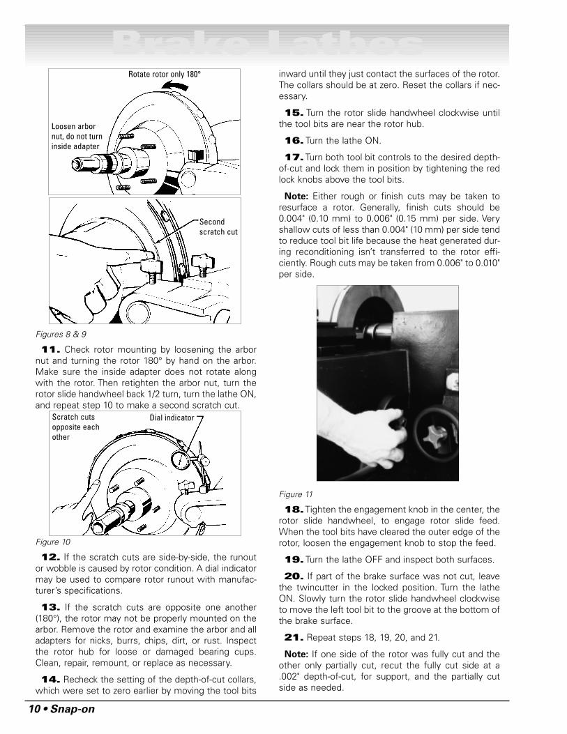
Figure 11
18.Tighten the engagement knob in the center, therotor slide handwheel, to engage rotor slide feed.When the tool bits have cleared the outer edge of therotor, loosen the engagement knob to stop the feed.
19. Turn the lathe OFF and inspect both surfaces.
20. If part of the brake surface was not cut, leavethe twincutter in the locked position. Turn the latheON. Slowly turn the rotor slide handwheel clockwiseto move the left tool bit to the groove at the bottom ofthe brake surface.
21. Repeat steps 18, 19, 20, and 21.
Note: If one side of the rotor was fully cut and theother only partially cut, recut the fully cut side at a.002" depth-of-cut, for support, and the partially cutside as needed.
Rotate rotor only 180°
Loosen arbornut, do not turninside adapter
Secondscratch cut
Scratch cutsopposite eachother
Dial indicator

Snap-on • 11
Reconditioning BrakeDrums
Measure the diameter of the brake drum with abrake drum micrometer. Determine if the drum will bewithin maximum rebore limits after reconditioning andthat its general condition is good.
Note: Most often the discard diameter is cast intothe brake drum, not the maximum “machine to” diam-eter.
Figure 12
Set Up and Machining1. Turn the end knob of the tool bar counterclock-
wise until the tool bit is fully retracted. Loosen the toolbar clamp nut and pull or retract the tool bar all theway back into the clamp.
2. Turn the drum slide handwheel counterclockwiseto move the slide to its maximum forward position.
3. Mount the drum on the arbor using the properadaptors, cones, and spacers as described in the pre-ceding DRUM MOUNTING section.
4. Wrap the drum silencer band snugly around theoutside of the drum. Be sure the band fully covers thedrum.
Figure 13
5. Slide the tool bar into the drum. Position theclamp and tool bar so the tool bit almost contacts thebrake surface at the back of the drum. Be sure the toolbar is not touching the brake surface at the outer edgeof the drum, then tighten the clamp nut to about 25 ft.lbs.
Note: The boring bar position must be changedwhenever preparing to machine a drum having a dif-ferent diameter and/or depth than the previous drum.
6. Turn the drum slide handwheel clockwise tomove the tool bit to the outer edge of the brake sur-face. Turn the lathe ON.
7. Check for drum runout. Runout is evident if theouter edge of the drum moves closer to and then fur-ther away from the tool bit while the drum is turning.A very small amount of runout is permissible. A largeamount of runout indicates either a bent drum or anincorrect mounting. To determine the cause of therunout a “scratch cut” procedure can be used as out-lined in steps 7A, 7B, and 7C.
7A Use the drum slide handwheel to move the toolbit about 1/2" in from the outer edge of the drum.Turn the end knob of the tool bar micrometerclockwise until the tool bit lightly contacts thedrum surface making a “scratch cut”approximately .001" deep. Turn the end knob ofthe micrometer counterclockwise one (1) full turnto move the tool bit away from the brake surface.
7B Turn the lathe OFF. Turn the drum slidehandwheel counterclockwise to move the tool bit1/4" further into the drum. Loosen the arbor nutand turn the drum 180˚ on the adaptors (do notallow the adaptors to turn on the arbor).Retighten the arbor nut. Turn the lathe ON.Slowly turn the end knob of the micrometerclockwise until a second “scratch cut” is made.Turn the end knob of the micrometercounterclockwise one (1) full turn.
7C Turn the lathe OFF. If the “scratch cuts” are sideby side the runout is in the drum and NOT in themounting. If the drum is not bent and the runoutis not severe, continue with step 8. A BENTDRUM MUST BE REPLACED. If the “scratchcuts” are opposite each other (180˚ apart) therunout is caused by poor mounting. In this case,inspect the mounting for cleanliness and theadaptors for burrs, nicks, and scratches, as wellas the bearing races for wear and/or looseness.Remount the drum and check for runout again. Ifrunout has been corrected, proceed to step 8.
Brake Lathes
12 • Snap-on
Brake Lathes
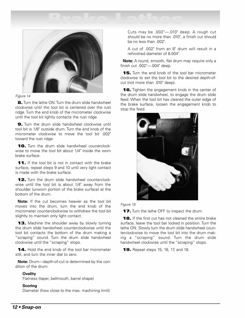
Figure 14
8.Turn the lathe ON. Turn the drum slide handwheelclockwise until the tool bit is centered over the rustridge. Turn the end knob of the micrometer clockwiseuntil the tool bit lightly contacts the rust ridge.
9. Turn the drum slide handwheel clockwise untiltool bit is 1/8" outside drum. Turn the end knob of themicrometer clockwise to move the tool bit .002"toward the rust ridge.
10. Turn the drum slide handwheel counerclock-wise to move the tool bit about 1/4" inside the wornbrake surface.
11. If the tool bit is not in contact with the brakesurface, repeat steps 9 and 10 until very light contactis made with the brake surface.
12. Turn the drum slide handwheel counterclock-wise until the tool bit is about 1/4" away from theshoulder (unworn portion of the brake surface) at thebottom of the drum.
Note: If the cut becomes heavier as the tool bitmoves into the drum, turn the end knob of themicrometer counterclockwise to withdraw the tool bitslightly to maintain only light contact.
13. Machine the shoulder away by slowly turningthe drum slide handwheel counterclockwise until thetool bit contacts the bottom of the drum making a“scraping” sound. Turn the drum slide handwheelclockwise until the “scraping” stops.
14. Hold the end knob of the tool bar micrometerstill, and turn the inner dial to zero.
Note: Drum—depth-of-cut is determined by the con-dition of the drum:
Ovality
Flatness (taper, bellmouth, barrel shape)
Scoring
Diameter (how close to the max. machining limit)
Cuts may be .002"—.010" deep. A rough cutshould be no more than .010", a finish cut shouldbe no less than .002".
A cut of .002" from an 8" drum will result in arefinished diameter of 8.004".
Note: A round, smooth, flat drum may require only afinish cut .002"—.004" deep.
15. Turn the end knob of the tool bar micrometerclockwise to set the tool bit to the desired depth-of-cut (not more than .010" deep).
16. Tighten the engagement knob in the center ofthe drum slide handwheel, to engage the drum slidefeed. When the tool bit has cleared the outer edge ofthe brake surface, loosen the engagement knob tostop the feed.
Figure 15
17. Turn the lathe OFF to inspect the drum.
18. If the first cut has not cleaned the entire brakesurface, leave the tool bar locked in position. Turn thelathe ON. Slowly turn the drum slide handwheel coun-terclockwise to move the tool bit into the drum mak-ing a “scraping” sound. Turn the drum slidehandwheel clockwise until the “scraping” stops.
19. Repeat steps 15, 16, 17, and 18.

Snap-on • 13
Brake Lathes
A
CB
L
KD
F
Hubbed Brake DrumsHubbed Brake Drums — Tapered cone adapters fitin the bearing seats, making contact near the middleof the bearing race whenever possible rather than nearan edge. Various adapters and spacers may be used tofill out the shaft of the arbor.
Hubless Brake Drums — A cone fits into the centerhole of the drum from the inside to center the drum onthe arbor. Select a hubless adapter which will fit insidethe drum, against the flat lug hole surface and eitherstraddle the boltholes to avoid mounting against a burr,or remove the burrs. Slip the hubless adapter onto thearbor followed by a spring, the cone, the drum, andanother hubless adapter. Fill out the shaft with spacersas needed.
Note: Refer to instructions in adapter kit for mount-ing Hubless drums and rotors.
Key to Mounting Adapters, Cones, and Related Parts
A. 1” Arbor
B. Flange Plate
C. Spring
D. Centering Cone
E. Rotor, Drum or Flywheel
F. Flange Plate
G. Spacer(s)
H. Self-Aligning Spacer
I. Arbor Nut
Note: The self-aligning spacer should always be usednext to the arbor nut when tightening. To avoid over-tightening, wrench tighten the arbor nut counterclock-wise until the drum and adapters begin to turn on thearbor, then continue to advance the wrench 1/16 of aturn. DO NOT overtighten the arbor nut.
Typical Drum Mounting Configurations
Figure 16

14 • Snap-on
Brake LathesMaintenance and
ServiceOiling
The bare metal parts are coated with an oil-solublerust preventative. It is not necessary to clean the rustpreventative from these parts. Before using the lathe,all bare metal parts should be wiped down with anoiled rag. Use a light machine oil for the initial and dailywipe downs when oiling the exposed bare metalparts. Do not oil the tool bar clamping surfaces on topof the slides.
Lead Screw Drive: Apply light machine oil to thebronze bushing at the end of the lead screw.
Felt Wipers: Apply light machine oil to the felt waywipers.
CleaningKeep the lathe as clean as possible for trouble free
operation as well as safety and longer lathe life. Use abrush to sweep metal chips and dust off the lathe. DONOT USE COMPRESSED AIR TO BLOW THE LATHECLEAN as chips and dust may be driven betweenmachined parts and into the ways causing unduewear. Wipe dust and chips from the slide clampingsurfaces before installing the tool bars.
Care of Arbors and Adaptors
Although the adaptors, arbors, and the
spindle are made of top grade steel and are
turned, hardened, and precision ground to
close tolerances, great care should be taken
in their use, handling, and storage. Even
the smallest nick, scratch, or nose chip can
cause incorrect rotor or drum alignment,
resulting in inaccurate machining.
Remove all adaptors from the arbor after machining adrum or rotor and wipe them clean—especially theinboard adaptor. When a finished drum or rotor isremoved from the arbor, the inboard adaptor maymove slightly away from the face of the arbor andallow metal chips to fall into the opening causing apoor mounting for the next drum or rotor.
Regularly inspect the faces and seating tapers of theadaptors for nicks and scratches; correct any flaw witha fine stone. If the damage cannot be corrected,replace the adaptor. Handle the adaptors and arborswith care and store them on individual hooks. DO NOTthrow them into a box. The adaptors are designed formounting drums and rotors only, DO NOT misuse theadaptors.
Spindle V-belt Replacement1. Disconnect the lathe from the power source.
2. Remove the two (2) screws securing the drivebelt cover and remove the cover.
3. Remove the two (2) nuts and washers from thestuds supporting the idler bracket tension screw, andcompletely back off the idler bracket tension screw.Slide the idler bracket off the studs and the pulleys outof the timing belts. Remove the timing belts from thespindle pulleys.
4. Loosen, but do not remove the four (4) screwssecuring the motor to the main frame. Lift the motorand remove the V-belt.
5. Hang the new V-belt in the spindle pulley, lift themotor and slip the belt into the motor pulley. Adjustthe V-belt tension as described in SPINDLE V-BELTADJUSTMENT below.
6. Hang the timing belts on the spindle pulleys andreplace the idler bracket assembly. Lift the idlerbracket to slide the timing belts onto the idler pulleys.
7. Replace the washers and nuts on the idlerbracket studs. Use a wrench to tighten the nuts, thenback the nuts off 1/4 to 1/2 turn. Adjust the timing belttension as described in SPINDLE TIMING BELTADJUSTMENT below.
8. Install the drive belt cover, and secure it with two(2) screws and washers.
Spindle V-belt Adjustment1. Disconnect the lathe from the power source.
2. Remove the two (2) screws and washers secur-ing the drive belt cover and remove the cover.
3. Loosen the four (4) motor mount screws to allowthe weight of the motor to rest on the V-belt.
4. Use a finger to press the V-belt in about 1/4" onthe left side, between the motor pulley and the spin-dle.
5. Tighten the motor mount screw to the left whilemaintaining the 1/4" deflection. Tighten the othermotor mount screws.
CAUTION

Snap-on • 15
Spindle Timing Belt ReplacementNote: Replace the timing belts in pairs only.
1. Disconnect the lathe from the power source.
2. Remove the two (2) screws and washers secur-ing the drive belt cover and remove the cover.
3. Remove the nuts and washers from the studssupporting the idler bracket. Loosen the lock nut of theidler bracket tension screw, and completely back offthe idler tension screw. Slide the idler bracket off thestuds and the pulleys out of the timing belts.
4. Hang the new timing belts on the spindle pulleysand replace the idler bracket assembly. Lift the idlerbracket to slide the timing belts onto the idler pulleys.
5. Replace the washers and nuts on the idler bracketstuds. Use a wrench to tighten the nuts, then back thenuts off 1/4 to 1/2 turn. Adjust the timing belt tensionas described in SPINDLE TIMING BELT ADJUSTMENT.
6. Install the drive belt cover and secure it with two(2) screws and washers.
Spindle Timing Belt Adjustment1. Disconnect the lathe from the power source.
2. Remove the two (2) screws and washers secur-ing the drive belt cover and remove the cover.
3. Determine which timing belt is the tighter of thetwo. Use the tighter belt to set the tension for bothtiming belts.
4. Loosen the two (2) nuts securing the jack shaftsupport to the main frame.
5. Loosen the lock nut of the adjustment screw onthe under side of the jack shaft support. Turn the screwto adjust the timing belt tension so it can be deflected1/8" to 1/4" by pressing against the left side of the beltbetween the jack shaft and the spindle.
6. When the tension is set, tighten the lock adjust-ment screw lock nut and then the jack shaft supportscrews.
7. Replace the yoke cover and secure it with the nut.
Tool Bar Adjustment1. Turn the micrometer dial counterclockwise to
unscrew the dial from the boring bar. Remove themicrometer dial assembly.
2. Unscrew the two (2) allen head cap screws fromthe tool holder end of the tool bar. Press the toolholder against a solid stop, pull the screws from theboring bar and carefully ease the bar away from thestop.
3. Clean all metal chips and dirty grease from all theworking parts.
4. Slip the spring into the bore of the tool bar.Grease the sleeve with white grease and slip it into thebore of the tool bar.
5. Slip the tool holder between the ears of the bor-ing bar, press the tool holder against a solid stop andinsert the allen head cap screws. Run the screws allthe way in.
7. Fully tighten one of the allen head cap screws,then back the micrometer dial out two turns.
8. Slowly loosen the allen head cap screw until thetool holder slips back.
9. Screw the micrometer all the way in and repeatsteps 7 and 8 for the other allen head cap screw.
Gib Adjustment1. Loosen the eight (8) cap screws (part #906353)
on the vertical face of the slide and loosen the four (4)button head screws (part #924759) on the end plate(925772). This allows the lead screw to float in hori-zontal and vertical directions to insure that the gibtightens across the dovetail, not the lead screw.
2. Tighten the three (3) gib set screws (part#925786) then back off each screw 1/4 turn.
3. Tighten the middle screw while moving the edgeof the slide farthest from the machine in an up-and-down motion. Tighten only until vertical motion is elim-inated. If more than slight resistance is felt whileturning the handwheel, the screw is too tight.
4. Tighten the remaining two (2) gib screws sepa-rately, while turning the handwheel to move the slideback and forth on the ways. Tighten until only slightresistance is felt as the handwheel is turned.
5.Turn the lathe ON. Run the slide all the way to theend of its travel (away from the arbor). While exertingslight pressure on the handwheel in the direction ofthe end-stop, tighten the four (4) cap screws in the ver-tical face of the slide, opposite the motor. This insuresperpendicularity between the end plate and the ways.
6.Tighten the four (4) button head screws in the endplate. This centers the lead screw.
7. Run the slide all the way in (to the arbor). Tightenthe four (4) cap screws on the vertical face of the slide,next to the motor. This centers the motor.
8. If a “clicking” sound is heard, loosen the four (4)cap screws on the motor vertically. When the soundstops, tighten the screws. Clicking is heard when theleadscrew/coupling is not running at a constant veloc-ity. Centering the motor eliminates that problem.
Brake Lathes

Snap-on Tools CompanyLimited One (1) Year Warranty
Snap-on Tools Company (the “Seller”) warrants only to the original purchaser that under normal use,care and service, the Equipment (except as otherwise provided herein) shall be free from defects inmaterial and workmanship for one year from the date of original invoice. Arbor runout is warrantedfor 30 calendar days from the date of original purchase. Belts are warranted for 90 calendar days fromthe date of original purchase.
SELLER’S OBLIGATIONS UNDER THIS WARRANTY ARE LIMITED SOLELY TO THE REPAIR OR, ATSELLER’S OPTION, REPLACEMENT OF EQUIPMENT OR PARTS WHICH TO SELLER’S SATISFAC-TION ARE DETERMINED TO BE DEFECTIVE AND WHICH ARE NECESSARY, IN SELLER’S JUDG-MENT, TO RETURN THIS EQUIPMENT TO GOOD OPERATING CONDITION. NO OTHERWARRANTIES, EXPRESS OR IMPLIED OR STATUTORY, INCLUDING WITHOUT LIMITATION ANYIMPLIED WARRANTY OF MERCHANTABILITY OR FITNESS FOR A PARTICULAR PURPOSE, SHALLAPPLY AND ALL SUCH WARRANTIES ARE HEREBY EXPRESSLY DISCLAIMED.
This Warranty does not cover (and separate charges for parts, labor, and related expenses shall applyto) any damage to, malfunctioning, inoperability or improper operation of the Equipment caused by,resulting from or attributable to (A) abuse, misuse or tampering; (B) alteration, modification or adjust-ment of the Equipment by other than Seller’s authorized representatives; (C) installation, repair ormaintenance (other than specified operator maintenance) of the Equipment or related equipment,attachments, peripherals or optional features by other than Seller’s authorized representatives; (D)improper or negligent use, application, operation, care, cleaning, storage or handling; (E) fire, water,wind, lightning or other natural causes; (F) adverse environmental conditions, including, without lim-itation, excessive heat, moisture, corrosive elements, dust or other air contaminants, radio frequencyinterference, electric power failure, power line voltages beyond those specified for the Equipment,unusual physical, electrical or electromagnetic stress and/or any other condition outside of the Seller’senvironmental specifications; (G) use of the Equipment in combination or connection with otherequipment, attachments, supplies or consumables not manufactured or supplied by Seller; or (H) fail-ure to comply with any applicable federal, state or local regulation, requirement or specification gov-erning emission analyzers and related supplies or consumables.
Repairs or replacements qualifying under this Warranty will be performed on regular business daysduring Seller’s normal working hours within a reasonable time following Purchaser’s request. Allrequests for Warranty service must be made during the stated Warranty period. This Warranty is non-transferable.
Brake Lathe EEBR308ABP includes:
EEBR308A Brake LatheAMM2500 Bench Kit (Bench, sign, tool board, chip funnel and bucket)
AMM0002 Basic Adapter Kit
Brake Lathe EEBR308ADP includes:
EEBR308A Brake LatheAMM2500 Bench Kit (Bench, sign, tool board, chip funnel and bucket)
AMM0005 Deluxe Adapter Kit
For Installation & Service & Parts, call Equiserv at 1-800-225-5786
Snap-on© is a trademark of Snap-on Technologies, Inc.2002 Snap-on Technologies, Inc.
Manufactured in USA for Snap-on2801 – 80th Street, Kenosha, WI 53141-1410
ZEEBR308A rev. 01 5102