EE6503 POWER EELCTRONICS AC VOLTAGE...
18
EE6503 POWER EELCTRONICS AC VOLTAGE CONTROLLERS 1. Introduction. AC voltage controllers (ac line voltage controllers) are employed to vary the RMS value of the alternating voltage applied to a load circuit.An ac voltage controller is a type of thyristor power converter which is used to convert a fixed voltage, fixed frequency ac input supply to obtain a variable voltage ac output. The RMS value of the ac output voltage and the ac power flow to the load is controlled by varying (adjusting) the trigger angl e ‘’ Fig.1 2. TYPE OF AC VOLTAGE CONTROLLERS The ac voltage controllers are classified into two types based on the type of input ac supply applied to the circuit. Single Phase AC Controllers. Three Phase AC Controllers. Single phase ac controllers operate with single phase ac supply voltage of 230V RMS at 50Hz in our country. Three phase ac controllers operate with 3 phase ac supply of 400V RMS at 50Hz supply frequency. Each type of controller may be sub divided into Uni-directional or half wave ac controller. Bi-directional or full wave ac controller. In brief different types of ac voltage controllers are Single phase half wave ac voltage controller (uni-directional controller). Single phase full wave ac voltage controller (bi-directional controller). AC Voltage Controller V 0(RMS) f S Variable AC RMSO/P Voltage AC Input Voltage f s V s f s
Transcript of EE6503 POWER EELCTRONICS AC VOLTAGE...

EE6503 POWER EELCTRONICS
AC VOLTAGE CONTROLLERS
1. Introduction.
AC voltage controllers (ac line voltage controllers) are employed to vary the RMS value
of the alternating voltage applied to a load circuit.An ac voltage controller is a type of thyristor
power converter which is used to convert a fixed voltage, fixed frequency ac input supply to
obtain a variable voltage ac output. The RMS value of the ac output voltage and the ac power
flow to the load is controlled by varying (adjusting) the trigger angle ‘’
Fig.1
2. TYPE OF AC VOLTAGE CONTROLLERS
The ac voltage controllers are classified into two types based on the type of input ac
supply applied to the circuit.
Single Phase AC Controllers.
Three Phase AC Controllers.
Single phase ac controllers operate with single phase ac supply voltage of 230V RMS at
50Hz in our country. Three phase ac controllers operate with 3 phase ac supply of 400V RMS at
50Hz supply frequency.
Each type of controller may be sub divided into
Uni-directional or half wave ac controller.
Bi-directional or full wave ac controller.
In brief different types of ac voltage controllers are
Single phase half wave ac voltage controller (uni-directional controller).
Single phase full wave ac voltage controller (bi-directional controller).
AC
VoltageController
V0(RMS)
fS
Variable AC
RMS O/P Voltage
AC
Input
Voltage
fs
Vs
fs

Three phase half wave ac voltage controller (uni-directional controller).
Three phase full wave ac voltage controller (bi-directional controller).
3. APPLICATIONS OF AC VOLTAGE CONTROLLERS
Lighting / Illumination control in ac power circuits.
Induction heating.
Industrial heating & Domestic heating.
Transformers tap changing (on load transformer tap changing).
Speed control of induction motors (single phase and poly phase ac induction
motor control).
AC magnet controls.
4. AC VOLTAGE CONTROL TECHNIQUES
There are two different types of thyristor control used in practice to control the ac power flow
1. Phase control
2. On-Off control
These are the two ac output voltage control techniques.
In On-Off control technique Thyristors are used as switches to connect the load circuit to the
ac supply (source) for a few cycles of the input ac supply and then to disconnect it for few input
cycles. The Thyristors thus act as a high speed contactor (or high speed ac switch).
4.1 PHASE CONTROL TECHNIQUE
In phase control the Thyristors are used as switches to connect the load circuit to the
input ac supply, for a part of every input cycle. That is the ac supply voltage is chopped using
Thyristors during a part of each input cycle.
The thyristor switch is turned on for a part of every half cycle, so that input supply
voltage appears across the load and then turned off during the remaining part of input half cycle
to disconnect the ac supply from the load.
By controlling the phase angle or the trigger angle ‘’ (delay angle), the output RMS
voltage across the load can be controlled.

The trigger delay angle ‘’ is defined as the phase angle (the value of t) at which the
thyristor turns on and the load current begins to flow.
SINGLE PHASE FULL WAVE AC VOLTAGE CONTROLLER (AC REGULATOR) OR
RMS VOLTAGE CONTROLLER WITH RESISTIVE LOAD
A single phase full wave ac voltage controller with a resistive load is shown in the figure below.
It is possible to control the ac power flow to the load in both the half cycles by adjusting the
trigger angle ' ' . Hence the full wave ac voltage controller is also referred to as to a
bidirectional controller.
Circuit Diagram:
OPERATION
Mode-1- From 0 to π
The thyristor T1 is forward biased during the positive half cycle of the input
supply voltage. The thyristor T1 is triggered at a delay angle of (0 . Considering
the ON thyristor T1 as an ideal closed switch the input supply voltage appears across the
load resistor RL and the output voltage vo=vs.
During t to radians. The load current flows through the ON thyristor T1
and through the load resistor RL in the downward direction during the conduction time of
T1 from t to radians
Mode-2- From 0 to π
At t , when the input voltage falls to zero the thyristor current (which is
flowing through the load resistor RL ) falls to zero and hence T1 naturally turns off . No
current flows in the circuit during t to . The thyristor T2 is forward biased

during the negative cycle of input supply and when thyristor T2 is triggered at a delay
angle , the output voltage follows the negative halfcycle of input from t )
to 2 . When T2 is ON, the load current flows in the reverse direction (upward direction)
through T2 during t to 2 radians. The time interval (spacing) between the gate
trigger pulses of T1 and T2 is kept at radians or 1800 . At t 2, the input supply
voltage falls to zero and hence the load current also falls to zero and thyristor T2 turn off
naturally.
Instead of using two SCR’s in parallel, a Triac can be used for full wave ac voltage
controlFor applications up to 400Hz,.
Phase control Thyristors which are relatively inexpensive, converter grade Thyristors
which are slower than fast switching inverter grade Thyristors are normally used.
Due to ac line commutation or natural commutation, there is no need of extra
commutation circuitry or components and the circuits for ac voltage controllers are very simple.
WAVEFORMS

SINGLE PHASE FULL WAVE AC VOLTAGE CONTROLLER (BIDIRECTIONAL
CONTROLLER) WITH RL LOAD
if we consider a single phase full wave ac voltage controller controlling the speed of a single
phase ac induction motor, the load which is the induction motor winding is an RL type of load,
where R represents the motor winding resistance and L represents the motor winding inductance.
A single phase full wave ac voltage controller circuit (bidirectional controller) with an RL load
using two thyristors T1 and T2 (T1 and T2 are two SCRs) connected in parallel is shown below.
The thyristor T1 is forward biased during the positive half cycle of input supply. Let us
assume that T1 is triggered at t , by applying a suitable gate trigger pulse to T1 during the
positive half cycle of input supply. The output voltage across the load follows the input supply
voltage when T1 is ON. The load current io flows through the thyristor T1 and through the load

in the downward direction. This load current pulse flowing through T1 can be considered as the
positive current pulse. Due to the inductance in the load, the load current io flowing through T1
would not fall to zero at t , when the input supply voltage starts to become negative. The
thyristor T1 will continue to conduct the load current until all the inductive energy stored in the
load inductor L is completely utilized and the load current through T1 falls to zero at t ,
where is referred to as the Extinction angle, (the value of t ) at which the load current falls to
zero. The extinction angle is measured from the point of the beginning of the positive half
cycle of input supply to the point where the load current falls to zero. The thyristor T1 conducts
from tto . The conduction angle of T1 is (, which depends on the delay angle
and the load impedance angle . The waveforms of the input supply voltage, the gate trigger
pulses of T1 and T2 , the thyristor current, the load current and the load voltage waveforms
appear as shown in the figure below.
Waveforms of single phase full wave ac voltage controller with RL load for .
Discontinuous load current operation occurs for and ; i.e., -, conduction
angle .

The RMS value of the output voltage and the load current may be varied by varying the trigger
angle . This circuit, AC RMS voltage controller can be used to regulate the RMS voltage
across the terminals of an ac motor (induction motor). It can be used to control the temperature
of a furnace by varying the RMS output voltage. For very large load inductance ‘L’ the SCR
may fail to commutate, after it is triggered and the load voltage will be a full sine wave (similar
to the applied input supply voltage and the output control will be lost) as long as the gating
signals are applied to the thyristors T1 and T2 . The load current waveform will appear as a full
continuous sine wave and the load current waveform lags behind the output sine wave by the
load power factor angle .

TO DERIVE AN EXPRESSION FOR RMS OUTPUT VOLTAGE O RMS V OF A SINGLE
PHASE FULL-WAVE AC VOLTAGE CONTROLLER WITH RL LOAD.
The RMS output voltage across the load can be varied by changing the trigger angle . For a
purely resistive load L 0 , therefore load power factor angle 0

4.2 PRINCIPLE OF ON-OFF CONTROL TECHNIQUE (INTEGRAL CYCLE
CONTROL)
Circuit Diagram:
LR R= Load Resistance
Fig.2: Single phase full wave AC voltage controller circuit
The basic principle of on-off control technique is explained with reference to a single phase full
wave ac voltage controller circuit shown below. The thyristor switches 1T and 2T are turned on
by applying appropriate gate trigger pulses to connect the input ac supply to the load for ‘n’
number of input cycles during the time interval ONt . The thyristor switches 1T and 2T are turned
off by blocking the gate trigger pulses for ‘m’ number of input cycles during the time interval
OFFt . The ac controller ON time ONt usually consists of an integral number of input cycles.
Waveforms:
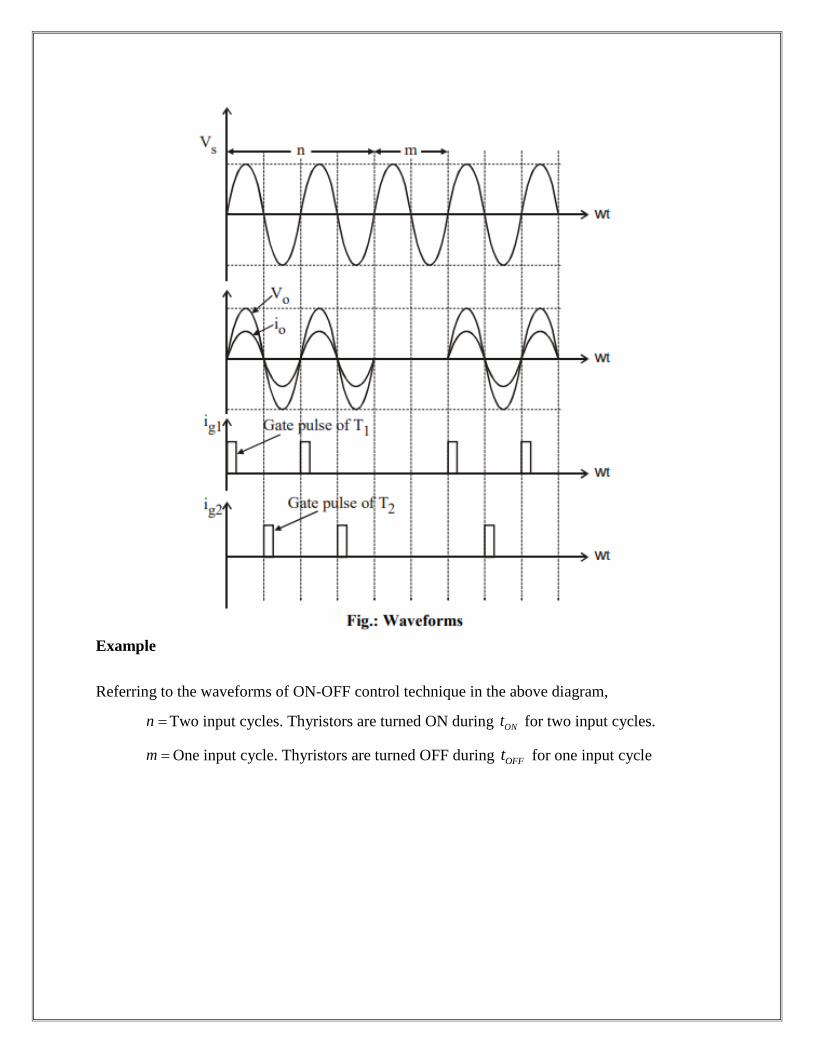
Example
Referring to the waveforms of ON-OFF control technique in the above diagram,
n Two input cycles. Thyristors are turned ON during ONt for two input cycles.
m One input cycle. Thyristors are turned OFF during OFFt for one input cycle

Fig.4: Power Factor
Operation:
Thyristors are turned ON precisely at the zero voltage crossings of the input supply.
Mode-1
The thyristor 1T is turned on at the beginning of each positive half cycle by applying the gate
trigger pulses to 1T as shown, during the ON time ONt . The load current flows in the positive
direction, which is the downward direction as shown in the circuit diagram when 1T conducts.
Mode-1
The thyristor 2T is turned on at the beginning of each negative half cycle, by applying gating
signal to the gate of 2T , during ONt . The load current flows in the reverse direction, which is the
upward direction when 2T conducts. Thus we obtain a bi-directional load current flow
(alternating load current flow) in a ac voltage controller circuit, by triggering the thyristors
alternately.
This type of control is used in applications which have high mechanical inertia and high
thermal time constant (Industrial heating and speed control of ac motors).Due to zero voltage and
zero current switching of Thyristors, the harmonics generated by switching actions are reduced.
For a sine wave input supply voltage,
sin 2 sins m Sv V t V t
SV RMS value of input ac supply = 2
mV = RMS phase supply voltage.
If the input ac supply is connected to load for ‘n’ number of input cycles and
disconnected for ‘m’ number of input cycles, then
,ON OFFt n T t m T
Where 1
Tf
= input cycle time (time period) and
f = input supply frequency.
ONt = controller on time = n T .
OFFt = controller off time = m T .
OT = Output time period = ON OFFt t nT mT .
We can show that,
Output RMS voltage
ON ONSO RMS i RMS
O O
t tV V V
T T
Where i RMSV is the RMS input supply voltage = SV .
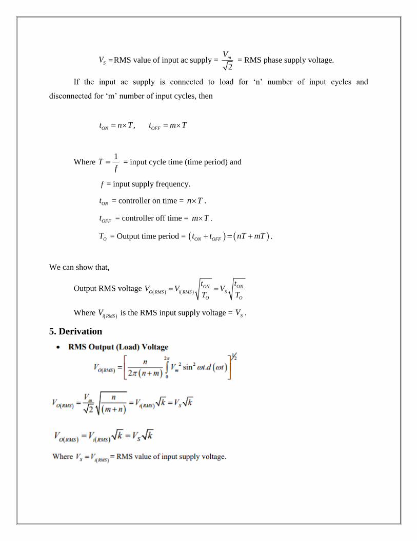
5. Derivation


5. Conclusion:
Thyristor based ac voltage controllers have high efficiency, flexibility in control and
require less maintenance. The disadvantage of ac voltage controllers is the introduction of
harmonics in the supply current and load voltage waveforms particularly at low output voltage
levels.
Power Factor Control
Power factor control, also known as correction of power factor, is the process of reducing the
amount of reactive power. The power electronic device used in this case is called a power factor
controller (PFC). From the power triangle (which comprises reactive, true and apparent power),
the reactive power is at right angle (90°) to the true power and is used to energize the magnetic
field. Although reactive power does not have a real value in electronic equipment, the bill for
electricity comprises real and reactive power costs. This makes it necessary to have power factor
controllers in electronic devices.
Power factor (k) is defined as the ratio of the real power (in kW) to the reactive power (in kVAr).
Its value ranges from 0 to 1. If a device has a power factor of 0.8 and above, it is said to be using
power efficiently. Incorporating a PFC ensures the power factor ranges from 0.95 to 0.99. Power
factor controllers are mainly in industrial equipment to minimize reactive power generated by
fluorescent lighting and electric motors.
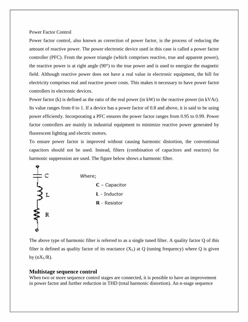
To ensure power factor is improved without causing harmonic distortion, the conventional
capacitors should not be used. Instead, filters (combination of capacitors and reactors) for
harmonic suppression are used. The figure below shows a harmonic filter.
The above type of harmonic filter is referred to as a single tuned filter. A quality factor Q of this
filter is defined as quality factor of its reactance (XL) at Q (tuning frequency) where Q is given
by (nXL/R).
Multistage sequence control When two or more sequence control stages are connected, it is possible to have an improvement
in power factor and further reduction in THD (total harmonic distortion). An n-stage sequence

control converter has n windings in the transformer secondary part with each rated es/n (the
source voltage).
When two AC converters are placed parallel to each other, the zero sequence way is created. A
little difference between the two converters causes a great zero sequence in circulating current.
The diagram below shows the parallel system of a converter. The direction of the current is anti-
clockwise with respect to that of the voltage system.
A cycloconverter refers to a frequency changer that can to change AC power from one frequency
to AC power at another frequency. This process is known as AC-AC conversion. It is mainly
used in electric traction, AC motors having variable speed and induction heating.
A cycloconverter can achieve frequency conversion in one stage and ensures that voltage and the
frequencies are controllable. In addition, the need to use commutation circuits is not necessary
because it utilizes natural commutation. Power transfer within a cycloconverter occurs in two
directions (bidirectional).
A major problem with cycloconverters is that when it is operating at small currents, there are
inefficiencies created with firing delay. Furthermore, operations are only smooth at frequencies
that are not equal half frequency input values. This is true because a cycloconverter is an AC-
AC converter that is phase controlled. Therefore, for it to give the required AC output voltage, it
has to do a selection of the voltage input segments by applying line (natural) commutation. This
explains why the output frequency is lower than the frequency input.
Harmonics in a cycloconverter are mainly affected by methods of control, overlap effect, the
number of pulses in a given cycle, operation mode and mode of conduction.
There are two types of cycloconverters−
Step Up cycloconverter − These types use natural commutation and give an output at
higher frequency than that of the input.
Step Down cycloconverter − This type uses forced commutation and results in an output
with a frequency lower than that of the input.
Cycloconverters are further classified into three categories −
Single phase to single-phase − This type of cycloconverter has two full wave converters
connected back to back. If one converter is operating the other one is disabled, no current
passes through it.
Three-phase to single-phase − This cycloconverter operates in four quadrants that is
(+V, +I) and (−V, −I) being the rectification modes and (+V, −I) and (−V, +I) being the
inversion modes.
Three-phase to three-phase − This type of cycloconverter is majorly used in AC
machine systems that are operating on three phase induction and synchronous machines.
MATRIX CONVERTER
A matrix converter is defined as a converter with a single stage of conversion. It
utilizes bidirectional controlled switch to achieve automatic conversion of power
from AC to AC. It provides an alternative to PWM voltage rectifier (double sided).
Matrix converters are characterized by sinusoidal waveforms that show the input
and output switching frequencies. The bidirectional switches make it possible to
have a controllable power factor input. In addition, the lack of DC links ensures it
has a compact design. The downside to matrix converters is that they lack bilateral

switches that are fully controlled and able to operate at high frequencies. Its
voltage ratio that is output to input voltage is limited.
There are three methods of matrix converter control −
Space vector modulation
Pulse width modulation
Venturi - analysis of function transfer
The Matrix Converter Circuit
The diagram given below shows a single-phase matrix converter.
It contains four bi-directional switches with each switch having the ability to
conduct in both forward blocking and reverse voltage.
Space Vector Modulation (SVM)
SVM refers to a method of algorithm used to control the PWM. It creates AC
waveforms that drive AC motors at various speeds. In the case of a three-phase
inverter having DC supply power, its three main legs at the output are connected to
a 3-phase motor.
The switches are under control to ensure that no two switches in the same leg are
ON at the same time. Simultaneous ON states could result in the DC supply
shorting. This leads to eight switching vectors where two are zero and six are
active vectors for switching.