EE2F2 - Music Technology 8. Subtractive Synthesis.
18
EE2F2 - Music Technology 8. Subtractive Synthesis
-
date post
22-Dec-2015 -
Category
Documents
-
view
229 -
download
4
Transcript of EE2F2 - Music Technology 8. Subtractive Synthesis.

EE2F2 - Music Technology
8. Subtractive Synthesis

Analogue Synthesisers Analogue synthesisers attempt to produce
realistic timbres using combinations of primitive, easy to generate waveforms, e.g.
Sine waves Square waves ‘Sawtooth’ waves Etc.
Two main methods of creating timbres: Subtractive synthesis – start with a waveform with lots
of harmonics and filter out the ones you don’t want Additive synthesis – build up the timbre a component at
a time using just sine waves at the harmonic frequencies

Subtractive Synthesis Subtractive synthesis: one of the earliest techniques but
still being used today Outline:
An oscillator produces a harmonically rich waveform A filter shapes the spectrum of that waveform to create the
desired timbre (subtracts unwanted harmonics) An amplifier shapes the envelope of the sound
This is the basis of contemporary sample+synthesis techniques and is related to functional physical modelling
In each case, the sound production techniques use the source-modifier approach
NB. We’ll only look at monophonic designs (i.e. only one note can be played at a time)

Source-Modifier Model Source
A signal generator Frequency is set by the
keyboard Waveform shape is set by the
controls Modifier
Filter + amplifier Shapes the waveform in the
frequency and the time domains
Filter characteristics and amplifier gain are varied by control voltages
Source Modifier
Front Panel Controls
Output

Control Voltage Sources
The control voltages influencing the source and modifier(s) are:
Keyboard output A control voltage proportional to the pitch of the key
pressed Envelope generator(s)
A slowly changing control voltage waveform triggered at the start of a note and then evolving throughout its duration
Low Frequency Oscillator (LFO) Slowly varying periodic control voltage. Used to
modulate the pitch and/or amplitude

A Subtractive Synthesiser Control voltages
(shown in green) determine the behaviour of:
Voltage Controlled Oscillator (VCO)
Voltage Controlled Filter (VCF)
Voltage Controlled Amplifier (VCA)
V.C.O.
L.F.O.
OutputV.C.F. V.C.A.
Env. Gen.Trigger
Source Modifier

A Subtractive Synthesiser
Audio signal (shown in red) is:
Generated by the source (VCO)
Modified by the VCF and the VCA
V.C.O.
L.F.O.
OutputV.C.F. V.C.A.
Env. Gen.Trigger

The V.C.O.
The Oscillator frequency is usually controlled by the keyboard with maybe a little modulation from the LFO
The waveform produced is selected from the front panel controls:

The V.C.F. The VCF modifies the
spectrum produced by the VCO
It is usually a low-pass filter with adjustable resonance
The cut-off frequency is (partly) controlled by control voltages from the keyboard and the envelope generator
Ga
in
Frequency
Cut-off frequencySet by control input
Peak at cut-offSet by resonance control

Using the VCO & VCF
Desired Spectrumf
VCO Output (sawtooth wave)
VCF Responsef f
Output waveform spectrum is built up by multiplying the source spectrum by the filter response

The V.C.A.
The VCA is simply a voltage controlled amplifier
The gain (amplification factor) is controlled by the control voltage
In Out
Gain control

E.g. Violin ensemble
The Envelope Generator Usually used to control the VCA and VCF to
‘shape’ the sound in terms of: Amplitude shape in the time domain Spectral content (evolving over time)
The ‘envelope’ is a slowly varying waveform triggered at the start of each note

Simple envelope generators
time
am
plit
ude
Note On
Note Off
On-Off envelope
Simply turns the output on when a note is
pressed and off when its released
time
am
plit
ude
Note On
Note Off
Attack-Release envelope
Gradual attack (ramp-up) and release (ramp-down). Attack and release rate
can be adjusted

ADSR Generator ADSR envelope
generator can create a wide variety of envelopes using just four parameters:
Attack: The initial rise time
Decay: Immediately following the attack
Sustain Level: A level maintained until the note is released
Release: The rate that the sound decays after the ‘note-off’
En
ve
lop
e L
ev
el
Time
Sustain Level
Attack Rate
Decay Rate
ReleaseRate
Note Pressed Note Released
A D S R

The L.F.O.
Generates a low frequency waveform (usually 1-10 Hz)
Usually selectable between sine or triangle waveform
Used as a control input to modulate: VCO frequency: Creating vibrato effect VCA gain: Creating tremolo effect VCF frequency: Creating special effects, e.g.
‘flanging’ effects
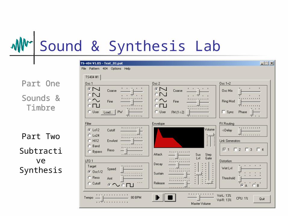
Sound & Synthesis Lab
Part One
Sounds & Timbre
Part Two
Subtractive Synthesis
Part One
Sounds & Timbre

Subtractive Synthesis Pros & Cons
Pros Huge variety of sounds from a simple architecture Not too many parameters, fairly easy to program Can emulate real instruments or create novel sounds
Cons Not always obvious how to program a particular
sound Some waveforms can’t be synthesised with the VCO
and VCF Almost all sounds have an ‘artificial’ nature

Summary Subtractive synthesis requires
Source(s) Modifier(s)
Source: VCO
Modifiers VCA, VCF
All three are controlled by: Keyboard Envelope generator LFO Other controllers (e.g. pedals, joysticks, etc.)