EE109 Arduino Digital I/O - University of Southern...
60
4.1 Unit 4 Microcontrollers (Arduino) Overview Digital I/O
Transcript of EE109 Arduino Digital I/O - University of Southern...
4.1
Unit 4
Microcontrollers (Arduino) Overview
Digital I/O
4.2
Introduction
• The primary way that software controls hardware is by manipulating individual bits
• We need to learn how to:
– Set a bit to a 1
– Clear a bit to a 0
– Check the value of a given bit (is it 0 or 1)
• Because computers do not access anything smaller than a byte (8-bits) we must use logic operations to manipulate individual bits within a byte
4.3
BIT FIDDLINGUsing software to perform logic on individual (or groups) of bits

4.4
Numbers in Other Bases in C/C++
• Suppose we want to place the binary value 00111010 into a char variable, v [i.e. char v;]
– We could convert to decimal on our own (5810) v = 58;
– All compilers support hexadecimal using the '0x' prefixv = 0x3a;
– Our Arduino compiler supports binary using the '0b' prefixv = 0b00111010;
• Important note: Compilers convert EVERYTHING to equivalent binary. The 3 alternatives above are equivalent because the compiler will take all 3 and place 00111010 in memory.– Use whichever base makes the most sense in any given situation
– It is your (the programmer's) choice…the compiler will end up converting to binary once it is compiled
4.5
Modifying Individual Bits
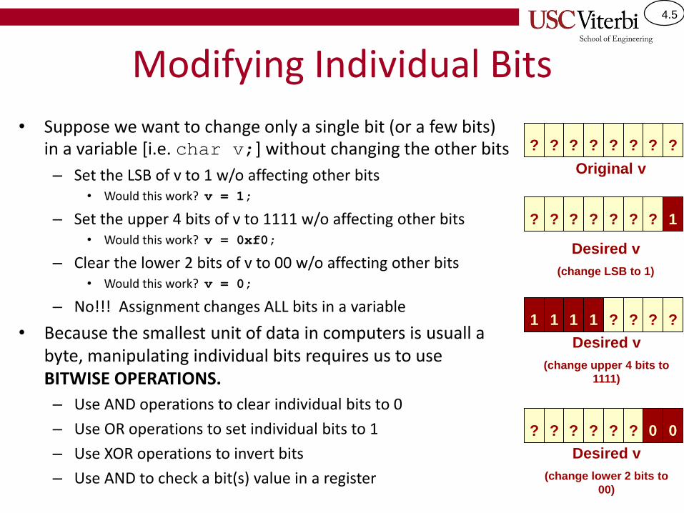
• Suppose we want to change only a single bit (or a few bits) in a variable [i.e. char v;] without changing the other bits
– Set the LSB of v to 1 w/o affecting other bits• Would this work? v = 1;
– Set the upper 4 bits of v to 1111 w/o affecting other bits• Would this work? v = 0xf0;
– Clear the lower 2 bits of v to 00 w/o affecting other bits• Would this work? v = 0;
– No!!! Assignment changes ALL bits in a variable
• Because the smallest unit of data in computers is usuall a byte, manipulating individual bits requires us to use BITWISE OPERATIONS.
– Use AND operations to clear individual bits to 0
– Use OR operations to set individual bits to 1
– Use XOR operations to invert bits
– Use AND to check a bit(s) value in a register
? ? ? ? ? ? ? ?
?
Desired v
(change LSB to 1)
? ? ? ? ? ? 1
Original v
1
Desired v
(change upper 4 bits to
1111)
1 1 1 ? ? ? ?
?
Desired v
(change lower 2 bits to
00)
? ? ? ? ? 0 0
4.6
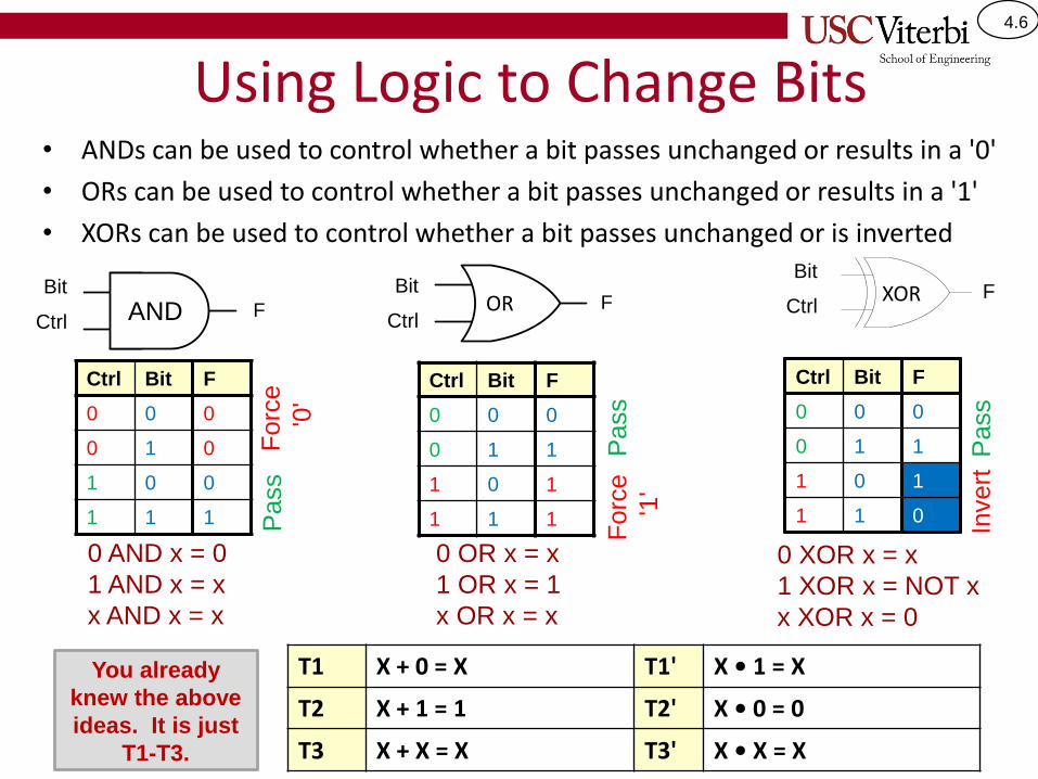
Using Logic to Change Bits• ANDs can be used to control whether a bit passes unchanged or results in a '0'
• ORs can be used to control whether a bit passes unchanged or results in a '1'
• XORs can be used to control whether a bit passes unchanged or is inverted
Y
XF
Y
XF
Ctrl Bit F
0 0 0
0 1 0
1 0 0
1 1 1
ANDBit
Ctrl
Pass
Forc
e
'0'
ZX
YXOR
Bit
CtrlF
Ctrl Bit F
0 0 0
0 1 1
1 0 1
1 1 0
Pass
Invert
Ctrl Bit F
0 0 0
0 1 1
1 0 1
1 1 1
Pass
Forc
e
'1'
Bit
CtrlOR
0 OR x = x
1 OR x = 1
x OR x = x
0 AND x = 0
1 AND x = x
x AND x = x
0 XOR x = x
1 XOR x = NOT x
x XOR x = 0
T1 X + 0 = X T1' X • 1 = X
T2 X + 1 = 1 T2' X • 0 = 0
T3 X + X = X T3' X • X = X
You already
knew the above
ideas. It is just
T1-T3.
4.7
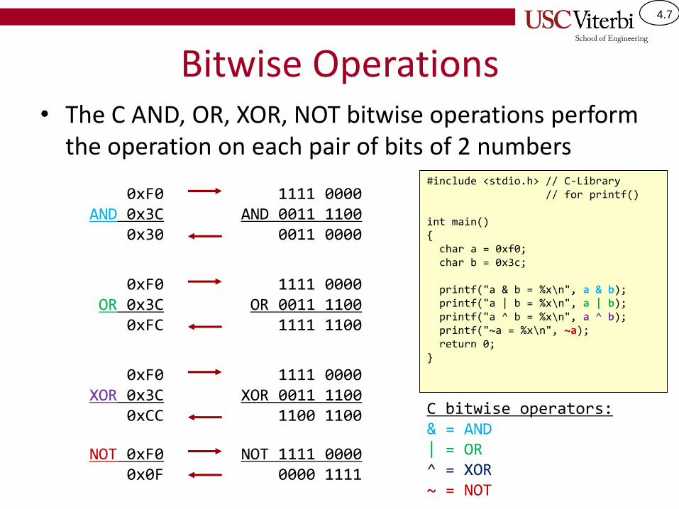
Bitwise Operations• The C AND, OR, XOR, NOT bitwise operations perform
the operation on each pair of bits of 2 numbers
0xF0AND 0x3C
0x30
1111 0000AND 0011 1100
0011 0000
0xF0OR 0x3C
0xFC
1111 0000OR 0011 1100
1111 1100
0xF0XOR 0x3C
0xCC
1111 0000XOR 0011 1100
1100 1100
#include <stdio.h> // C-Library// for printf()
int main(){char a = 0xf0;char b = 0x3c;
printf("a & b = %x\n", a & b);printf("a | b = %x\n", a | b);printf("a ^ b = %x\n", a ^ b);printf("~a = %x\n", ~a);return 0;
}
NOT 0xF00x0F
NOT 1111 00000000 1111
C bitwise operators:& = AND| = OR^ = XOR~ = NOT
4.8
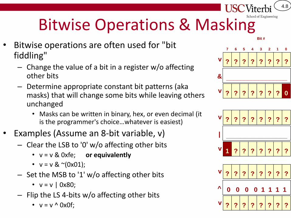
Bitwise Operations & Masking• Bitwise operations are often used for "bit
fiddling"– Change the value of a bit in a register w/o affecting
other bits
– Determine appropriate constant bit patterns (aka masks) that will change some bits while leaving others unchanged• Masks can be written in binary, hex, or even decimal (it
is the programmer's choice…whatever is easiest)
• Examples (Assume an 8-bit variable, v)– Clear the LSB to '0' w/o affecting other bits
• v = v & 0xfe; or equivalently
• v = v & ~(0x01);
– Set the MSB to '1' w/o affecting other bits• v = v | 0x80;
– Flip the LS 4-bits w/o affecting other bits• v = v ^ 0x0f;
?v ? ? ? ? ? ? ?
7
& _________________
?v ? ? ? ? ? ? 0
?v ? ? ? ? ? ? ?
| _________________
?v ? ? ? ? ? ?1
?v ? ? ? ? ? ? ?
^ 0 0 0 0 1 1 1 1
?v ? ? ? ? ? ??
Bit #
6 5 4 3 2 1 0
4.9
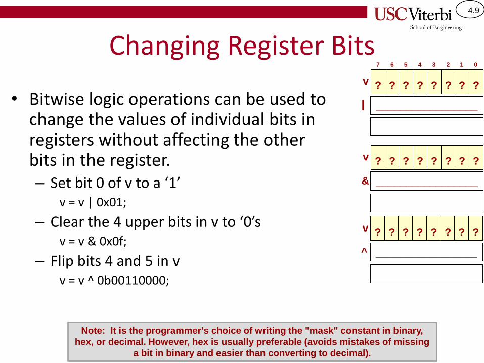
Changing Register Bits
• Bitwise logic operations can be used to change the values of individual bits in registers without affecting the other bits in the register.– Set bit 0 of v to a ‘1’
v = v | 0x01;
– Clear the 4 upper bits in v to ‘0’sv = v & 0x0f;
– Flip bits 4 and 5 in vv = v ^ 0b00110000;
?v ? ? ? ? ? ? ?
| _________________
?v ? ? ? ? ? ? ?
& _________________
?v ? ? ? ? ? ? ?
^ _________________
7 6 5 4 3 2 1 0
Note: It is the programmer's choice of writing the "mask" constant in binary,
hex, or decimal. However, hex is usually preferable (avoids mistakes of missing
a bit in binary and easier than converting to decimal).
4.10
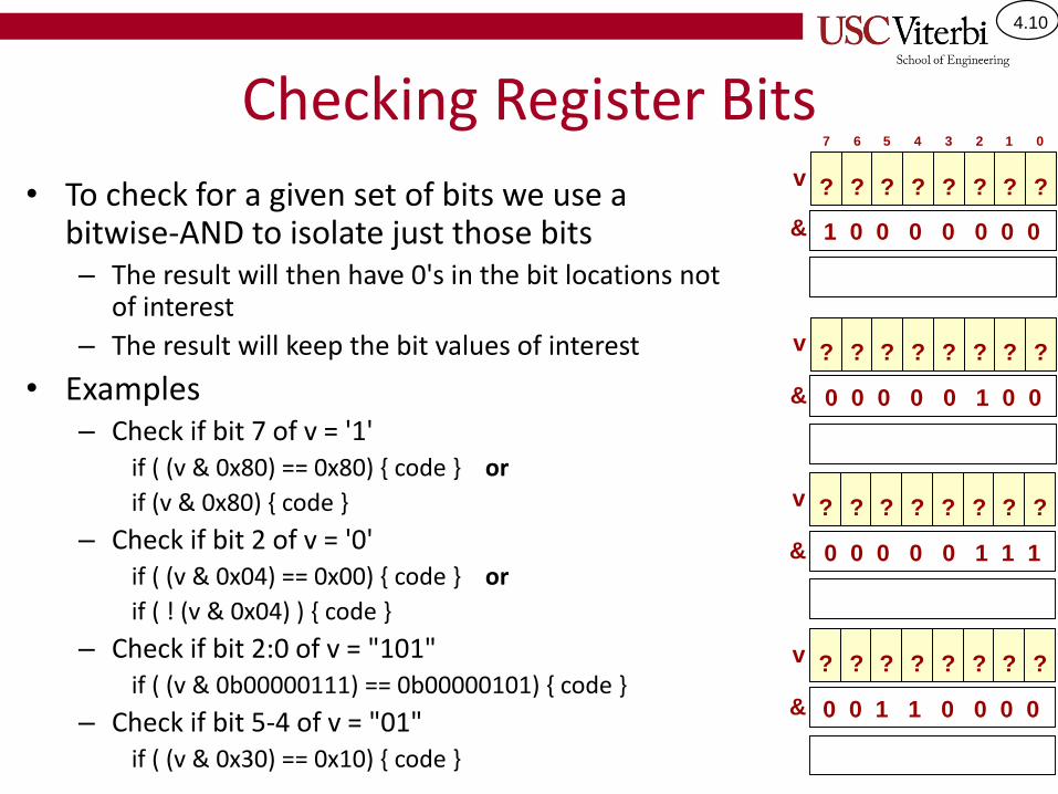
Checking Register Bits
• To check for a given set of bits we use a bitwise-AND to isolate just those bits– The result will then have 0's in the bit locations not
of interest
– The result will keep the bit values of interest
• Examples– Check if bit 7 of v = '1'
if ( (v & 0x80) == 0x80) { code } or
if (v & 0x80) { code }
– Check if bit 2 of v = '0'if ( (v & 0x04) == 0x00) { code } or
if ( ! (v & 0x04) ) { code }
– Check if bit 2:0 of v = "101"if ( (v & 0b00000111) == 0b00000101) { code }
– Check if bit 5-4 of v = "01"if ( (v & 0x30) == 0x10) { code }
?v ? ? ? ? ? ? ?
& 1 0 0 0 0 0 0 0
?v ? ? ? ? ? ? ?
& 0 0 0 0 0 1 0 0
?v ? ? ? ? ? ? ?
& 0 0 0 0 0 1 1 1
?v ? ? ? ? ? ? ?
& 0 0 1 1 0 0 0 0
7 6 5 4 3 2 1 0
4.11
Short Notation for Operations
• In C, assignment statements of the form
– x = x op y;
• Can be shortened to
– x op= y;
• Example:
– x = x + 1; can be written as x += 1;
• The preceding operations can be written as
– v|= 0x01;
– v &= 0x0f;
– v ^= 0b00110000;
4.12
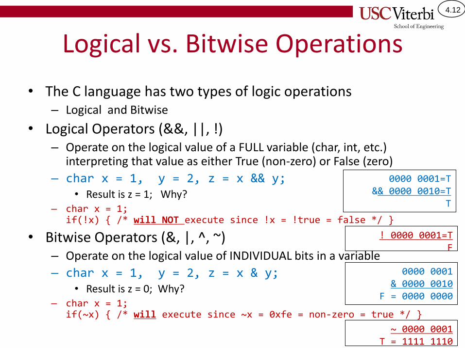
Logical vs. Bitwise Operations
• The C language has two types of logic operations– Logical and Bitwise
• Logical Operators (&&, ||, !) – Operate on the logical value of a FULL variable (char, int, etc.)
interpreting that value as either True (non-zero) or False (zero)
– char x = 1, y = 2, z = x && y;• Result is z = 1; Why?
– char x = 1; if(!x) { /* will NOT execute since !x = !true = false */ }
• Bitwise Operators (&, |, ^, ~)– Operate on the logical value of INDIVIDUAL bits in a variable
– char x = 1, y = 2, z = x & y;• Result is z = 0; Why?
– char x = 1;if(~x) { /* will execute since ~x = 0xfe = non-zero = true */ }
0000 0001=T&& 0000 0010=T
T
0000 0001& 0000 0010
F = 0000 0000
! 0000 0001=TF
~ 0000 0001T = 1111 1110

4.13
ARDUINO BOARD INTRO

4.14
Arduino Uno
• The Arduino Uno is a microcomputer development board based on the Atmel ATmega328P 8-bit processor.
• Most microcomputer manufacturers (Atmel, Freescale, etc.) produce small PC boards with their chips on them for engineers to experiment with and hopefully generate sales of the product.
http://arduino.cc/en/Main/ArduinoBoardUno
Atmega328P 8-bit processor
Printed circuit (PC) board with processor and other circuits for programming the system and
interfacing other devices
4.15
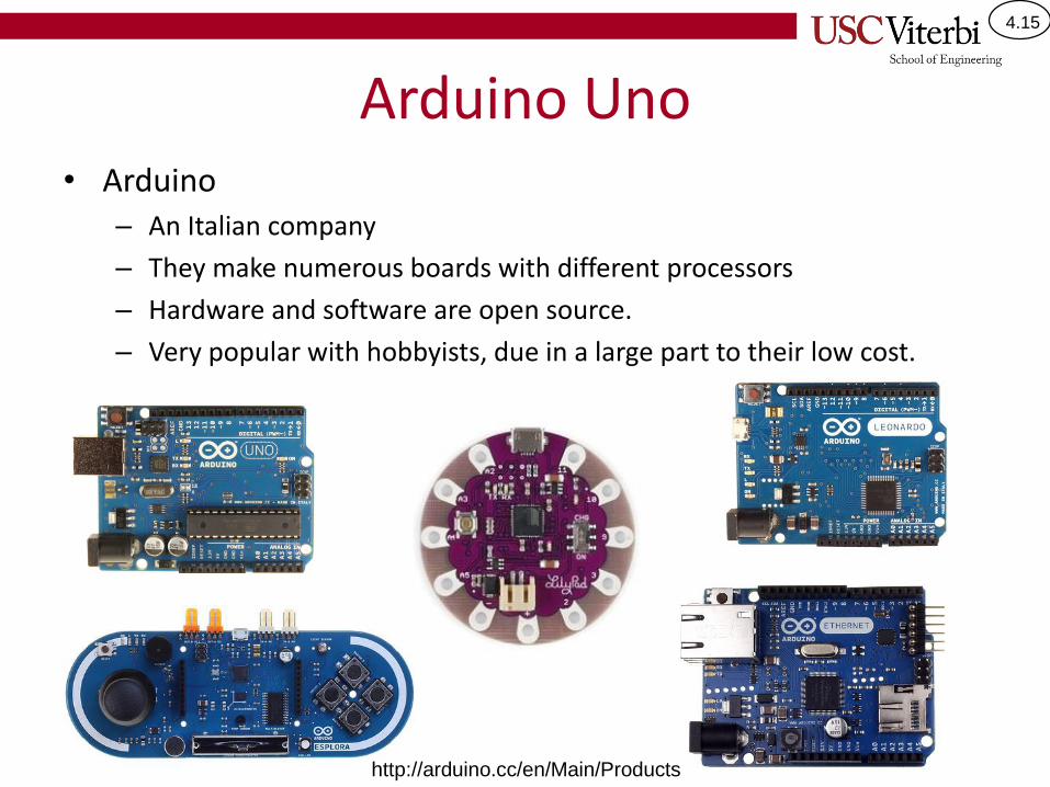
Arduino Uno• Arduino
– An Italian company
– They make numerous boards with different processors
– Hardware and software are open source.
– Very popular with hobbyists, due in a large part to their low cost.
http://arduino.cc/en/Main/Products
4.16
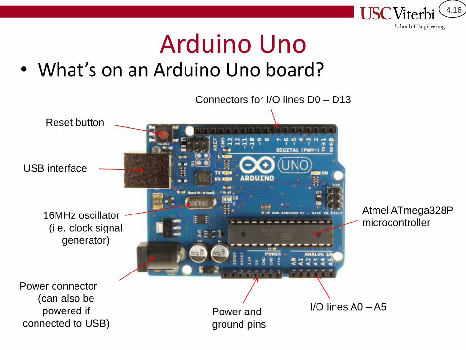
Arduino Uno• What’s on an Arduino Uno board?
Atmel ATmega328P
microcontroller16MHz oscillator
(i.e. clock signal
generator)
USB interface
Power connector
(can also be
powered if
connected to USB)
Reset button
Connectors for I/O lines D0 – D13
I/O lines A0 – A5Power and
ground pins
4.17
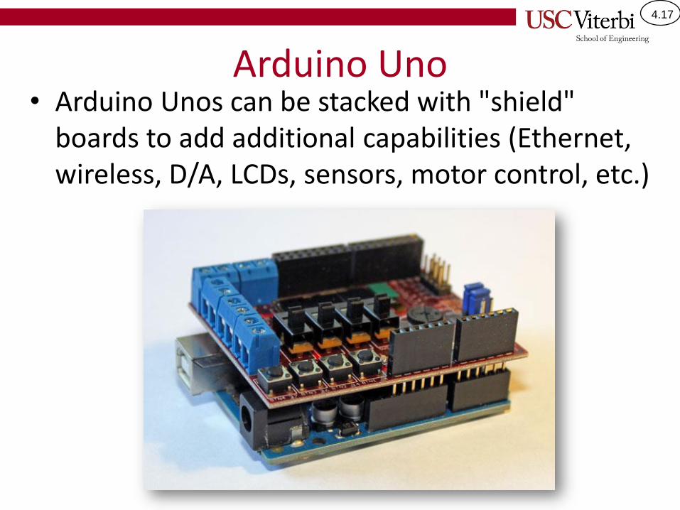
Arduino Uno• Arduino Unos can be stacked with "shield"
boards to add additional capabilities (Ethernet, wireless, D/A, LCDs, sensors, motor control, etc.)
4.18
ARDUINO DIGITAL I/OControlling the pins of the Arduino to be digital inputs and outputs
4.19
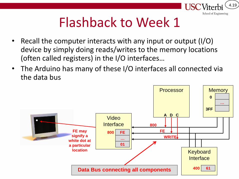
Flashback to Week 1• Recall the computer interacts with any input or output (I/O)
device by simply doing reads/writes to the memory locations (often called registers) in the I/O interfaces…
• The Arduino has many of these I/O interfaces all connected via the data bus
Video
Interface
FE may
signify a
white dot at
a particular
location
…
800
Processor Memory
A D C
800
FE
WRITE
…
0
3FF
FE
01
Keyboard
Interface
61400Data Bus connecting all components

4.20
Atmel ATmega328P
• The Arduino Uno is based on an Atmel ATmega328P 8-bit microcontroller
– 32kb of FLASH ROM
– 2048 bytes of RAM
– 23 I/O lines
– 3 timer/counters
– Serial/SPI/I2C interfaces
– A/D converterData Bus
Processor
Mem.

4.21
Arduino Digital I/O• ATmega328P has 23 pins on the chip that can be
connected to other devices (switches, LEDs, motors, etc.)
– Other members of the ATmega family may have more or less lines.
– The Arduino Uno can make use of only 20 of these lines.
• Each pin can be used as a digital input or a digital output
– For output pins: Your code determines what value ('1' or '0') appears
– For input pins: Your code senses/reads what value another device is putting on the pin
Main Point: Individual pins on the Arduino can be used as inputs OR outputs

4.22
Groups B, C and D
• The Arduino provides around 20 separate digital input/output bits that we can use to interface to external devices
• Recall computers don't access individual bits but instead the byte (8-bits) is the smallest unit of access
• Thus to deal with our digital inputs we will put the bits into 3 groups: Group B, C, and D– We often refer to these groups as "ports"
but you'll see that "port" is used in multiple places so we'll generally use "group"
Gro
up C
Gro
up D
Gro
up B
Software to Arduino Name Mapping
Group B bit5-bit0 = DIG13-DIG8
Group C bit5-bit0 = A5-A0
Group D bit7-bit0 = DIG7-DIG0
4.23
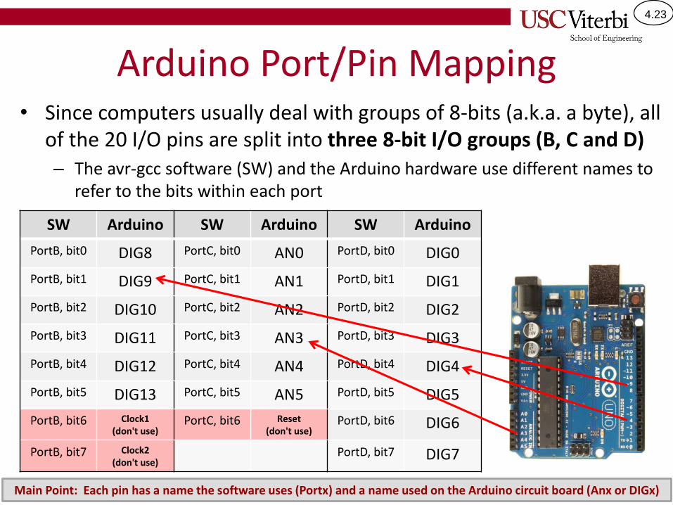
Arduino Port/Pin Mapping• Since computers usually deal with groups of 8-bits (a.k.a. a byte), all
of the 20 I/O pins are split into three 8-bit I/O groups (B, C and D)– The avr-gcc software (SW) and the Arduino hardware use different names to
refer to the bits within each port
SW Arduino SW Arduino SW Arduino
PortB, bit0 DIG8 PortC, bit0 AN0 PortD, bit0 DIG0
PortB, bit1 DIG9 PortC, bit1 AN1 PortD, bit1 DIG1
PortB, bit2 DIG10 PortC, bit2 AN2 PortD, bit2 DIG2
PortB, bit3 DIG11 PortC, bit3 AN3 PortD, bit3 DIG3
PortB, bit4 DIG12 PortC, bit4 AN4 PortD, bit4 DIG4
PortB, bit5 DIG13 PortC, bit5 AN5 PortD, bit5 DIG5
PortB, bit6 Clock1(don't use)
PortC, bit6 Reset (don't use)
PortD, bit6 DIG6
PortB, bit7 Clock2(don't use)
PortD, bit7 DIG7
Main Point: Each pin has a name the software uses (Portx) and a name used on the Arduino circuit board (Anx or DIGx)
4.24
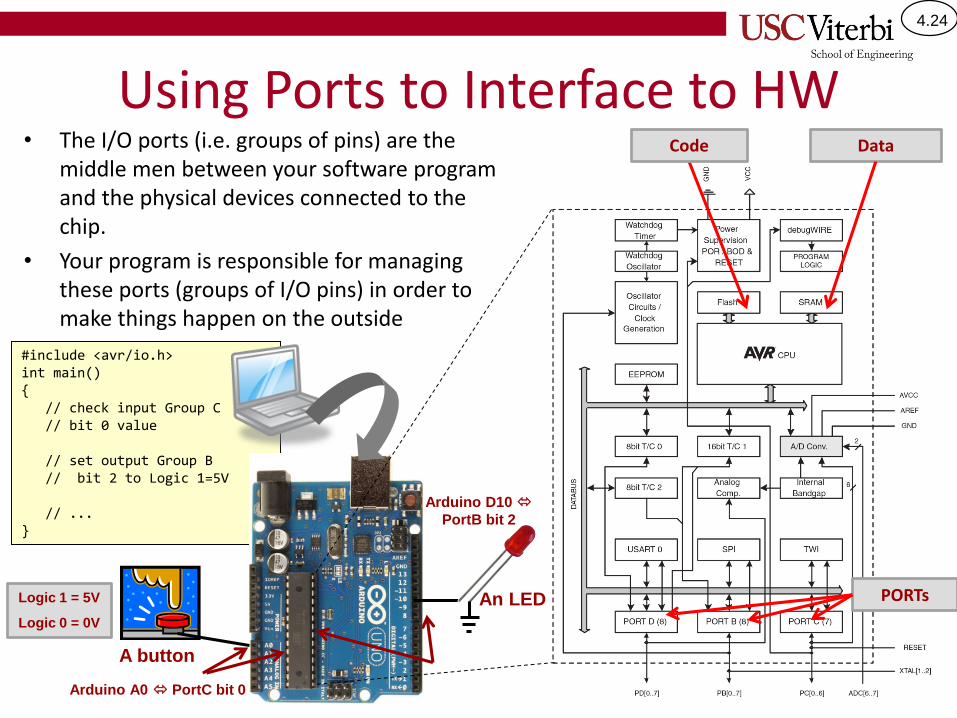
Using Ports to Interface to HW• The I/O ports (i.e. groups of pins) are the
middle men between your software program and the physical devices connected to the chip.
• Your program is responsible for managing these ports (groups of I/O pins) in order to make things happen on the outside
#include <avr/io.h>int main(){
// check input Group C // bit 0 value
// set output Group B // bit 2 to Logic 1=5V
// ... }
Code Data
PORTs
Arduino A0 PortC bit 0
A button
An LED
Arduino D10
PortB bit 2
Logic 1 = 5V
Logic 0 = 0V
4.25
Overview
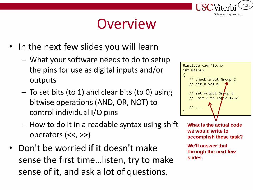
• In the next few slides you will learn
– What your software needs to do to setup the pins for use as digital inputs and/or outputs
– To set bits (to 1) and clear bits (to 0) using bitwise operations (AND, OR, NOT) to control individual I/O pins
– How to do it in a readable syntax using shift operators (<<, >>)
• Don't be worried if it doesn't make sense the first time…listen, try to make sense of it, and ask a lot of questions.
#include <avr/io.h>int main(){
// check input Group C // bit 0 value
// set output Group B // bit 2 to Logic 1=5V
// ... }
What is the actual code
we would write to
accomplish these task?
We'll answer that
through the next few
slides.
4.26
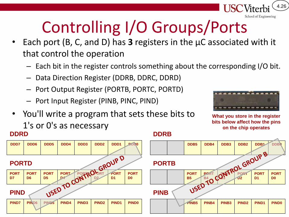
Controlling I/O Groups/Ports• Each port (B, C, and D) has 3 registers in the µC associated with it
that control the operation– Each bit in the register controls something about the corresponding I/O bit.
– Data Direction Register (DDRB, DDRC, DDRD)
– Port Output Register (PORTB, PORTC, PORTD)
– Port Input Register (PINB, PINC, PIND)
• You'll write a program that sets these bits to 1's or 0's as necessary
PORT
D7
PORT
D6
PORT
D5
PORT
D4
PORT
D3
PORT
D2
PORT
D0
PORT
D1
PORTD
PORT
B5
PORT
B4
PORT
B3
PORT
D2
PORT
D0
PORT
D1
PORTB
PIND7 PIND6 PIND5 PIND4 PIND3 PIND2 PIND0PIND1
PIND
PINB5 PINB4 PINB3 PIND2 PIND0PIND1
PINB
DDD7 DDD6 DDD5 DDD4 DDD3 DDD2 DDD0DDD1
DDRD
DDB5 DDB4 DDB3 DDB2 DDB0DDB1
DDRB
What you store in the register
bits below affect how the pins
on the chip operates
4.27
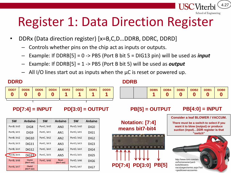
Register 1: Data Direction Register• DDRx (Data direction register) [x=B,C,D…DDRB, DDRC, DDRD]
– Controls whether pins on the chip act as inputs or outputs.
– Example: If DDRB[5] = 0 -> PB5 (Port B bit 5 = DIG13 pin) will be used as input
– Example: If DDRB[5] = 1 -> PB5 (Port B bit 5) will be used as output
– All I/O lines start out as inputs when the µC is reset or powered up.
0 0 0 0 1 1 11
DDRD
1 0 0 0 00
DDRB
DDD7 DDD6 DDD5 DDD4 DDR3 DDD2 DDD0DDR1 DDB5 DDB4 DDB3 DDB2 DDB0DDB1
PD[7:4] = INPUT PD[3:0] = OUTPUT PB[5] = OUTPUT
PD[3:0]PD[7:4] PB[5]
PB[4:0] = INPUT
Consider a leaf BLOWER / VACCUM.
There must be a switch to select if you
want it to blow (output) or produce
suction (input)…DDR register is that
"switch"
http://www.toro.com/en-
us/homeowner/yard-
tools/blowers-
vacs/pages/series.aspx?sid
=gasblowervacsseries
Notation: [7:4]
means bit7-bit4
4.28
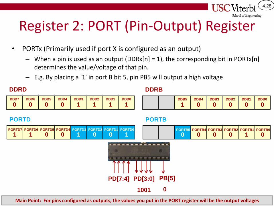
Register 2: PORT (Pin-Output) Register
• PORTx (Primarily used if port X is configured as an output)
– When a pin is used as an output (DDRx[n] = 1), the corresponding bit in PORTx[n] determines the value/voltage of that pin.
– E.g. By placing a '1' in port B bit 5, pin PB5 will output a high voltage
0 0 0 0 1 1 11
DDRD
1 0 0 0 00
DDRB
DDD7 DDD6 DDD5 DDD4 DDD3 DDD2 DDD0DDD1 DDB5 DDB4 DDB3 DDB2 DDB0DDB1
PD[3:0]PD[7:4] PB[5]
1 1 0 0 1 0 10
PORTD
0 0 0 0 01
PORTB
PORTD7 PORTD6 PORTD5 PORTD4 PORTD3 PORTD2 PORTD0PORTD1 PORTB5 PORTB4 PORTB3 PORTB2 PORTB0PORTB1
1001 0
Main Point: For pins configured as outputs, the values you put in the PORT register will be the output voltages
4.29
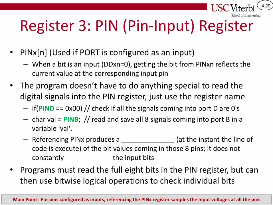
Register 3: PIN (Pin-Input) Register
• PINx[n] (Used if PORT is configured as an input)– When a bit is an input (DDxn=0), getting the bit from PINxn reflects the
current value at the corresponding input pin
• The program doesn’t have to do anything special to read the digital signals into the PIN register, just use the register name– if(PIND == 0x00) // check if all the signals coming into port D are 0's
– char val = PINB; // read and save all 8 signals coming into port B in a variable 'val'.
– Referencing PINx produces a ______________ (at the instant the line of code is execute) of the bit values coming in those 8 pins; it does not constantly ____________ the input bits
• Programs must read the full eight bits in the PIN register, but can then use bitwise logical operations to check individual bits
Main Point: For pins configured as inputs, referencing the PINx register samples the input voltages at all the pins
4.30
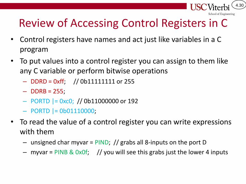
Review of Accessing Control Registers in C• Control registers have names and act just like variables in a C
program
• To put values into a control register you can assign to them like any C variable or perform bitwise operations– DDRD = 0xff; // 0b11111111 or 255
– DDRB = 255;
– PORTD |= 0xc0; // 0b11000000 or 192
– PORTD |= 0b01110000;
• To read the value of a control register you can write expressions with them– unsigned char myvar = PIND; // grabs all 8-inputs on the port D
– myvar = PINB & 0x0f; // you will see this grabs just the lower 4 inputs
4.31
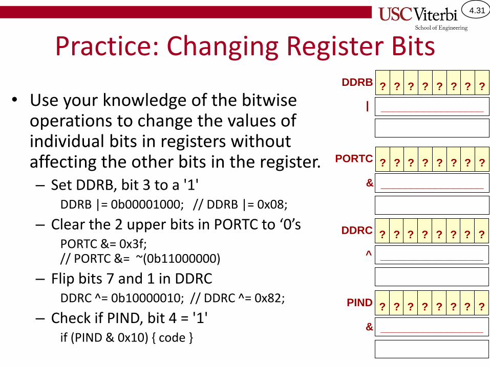
Practice: Changing Register Bits
• Use your knowledge of the bitwise operations to change the values of individual bits in registers without affecting the other bits in the register.– Set DDRB, bit 3 to a '1'
DDRB |= 0b00001000; // DDRB |= 0x08;
– Clear the 2 upper bits in PORTC to ‘0’sPORTC &= 0x3f; // PORTC &= ~(0b11000000)
– Flip bits 7 and 1 in DDRCDDRC ^= 0b10000010; // DDRC ^= 0x82;
– Check if PIND, bit 4 = '1'if (PIND & 0x10) { code }
?DDRB ? ? ? ? ? ? ?
| _________________
?PORTC ? ? ? ? ? ? ?
& _________________
?DDRC ? ? ? ? ? ? ?
^ _________________
?PIND ? ? ? ? ? ? ?
& _________________

4.32
EXAMPLES
4.33
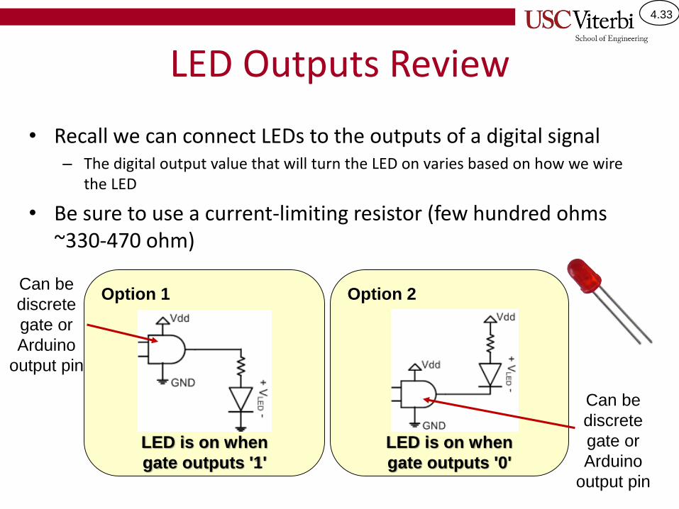
LED Outputs Review
• Recall we can connect LEDs to the outputs of a digital signal– The digital output value that will turn the LED on varies based on how we wire
the LED
• Be sure to use a current-limiting resistor (few hundred ohms ~330-470 ohm)
Option 1 Option 2
LED is on when
gate outputs '1'
LED is on when
gate outputs '0'
Can be
discrete
gate or
Arduino
output pin
Can be
discrete
gate or
Arduino
output pin
4.34
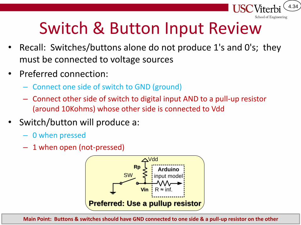
Switch & Button Input Review• Recall: Switches/buttons alone do not produce 1's and 0's; they
must be connected to voltage sources
• Preferred connection: – Connect one side of switch to GND (ground)
– Connect other side of switch to digital input AND to a pull-up resistor (around 10Kohms) whose other side is connected to Vdd
• Switch/button will produce a:– 0 when pressed
– 1 when open (not-pressed)
Preferred: Use a pullup resistor
Vdd
SW
R ≈ inf.
Arduino
input model
Rp
Vin
Main Point: Buttons & switches should have GND connected to one side & a pull-up resistor on the other
4.35
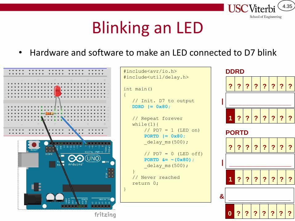
Blinking an LED• Hardware and software to make an LED connected to D7 blink
?
PORTD
? ? ? ? ? ? ?
| _________________
?? ? ? ? ? ?1
#include<avr/io.h>
#include<util/delay.h>
int main()
{
// Init. D7 to output
DDRD |= 0x80;
// Repeat forever
while(1){
// PD7 = 1 (LED on)
PORTD |= 0x80;
_delay_ms(500);
// PD7 = 0 (LED off)
PORTD &= ~(0x80);
_delay_ms(500);
}
// Never reached
return 0;
}
& _________________
?? ? ? ? ? ?0
?
DDRD
? ? ? ? ? ? ?
| _________________
?? ? ? ? ? ?1
4.36
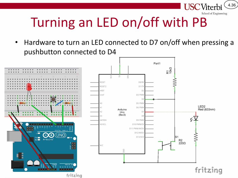
Turning an LED on/off with PB• Hardware to turn an LED connected to D7 on/off when pressing a
pushbutton connected to D4
4.37
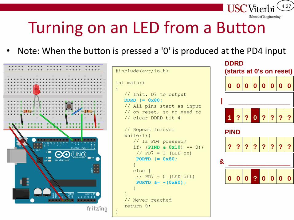
Turning on an LED from a Button• Note: When the button is pressed a '0' is produced at the PD4 input
?
PIND
? ? ? ? ? ? ?
& _________________
00 0 ? 0 0 00
#include<avr/io.h>
int main()
{
// Init. D7 to output
DDRD |= 0x80;
// All pins start as input
// on reset, so no need to
// clear DDRD bit 4
// Repeat forever
while(1){
// Is PD4 pressed?
if( (PIND & 0x10) == 0){
// PD7 = 1 (LED on)
PORTD |= 0x80;
}
else {
// PD7 = 0 (LED off)
PORTD &= ~(0x80);
}
}
// Never reached
return 0;
}
0
DDRD
(starts at 0's on reset)
0 0 0 0 0 0 0
| _________________
?? ? 0 ? ? ?1
4.38
Arduino
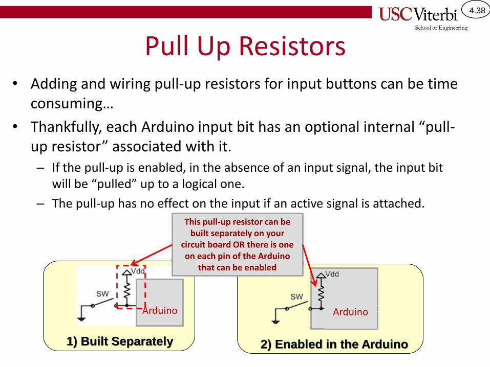
Pull Up Resistors• Adding and wiring pull-up resistors for input buttons can be time
consuming…
• Thankfully, each Arduino input bit has an optional internal “pull-up resistor” associated with it.– If the pull-up is enabled, in the absence of an input signal, the input bit
will be “pulled” up to a logical one.
– The pull-up has no effect on the input if an active signal is attached.
1) Built Separately
This pull-up resistor can be built separately on your
circuit board OR there is one on each pin of the Arduino
that can be enabled
Arduino
2) Enabled in the Arduino
Arduino
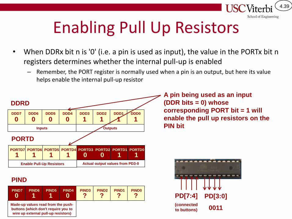
4.39
Enabling Pull Up Resistors• When DDRx bit n is '0' (i.e. a pin is used as input), the value in the PORTx bit n
registers determines whether the internal pull-up is enabled– Remember, the PORT register is normally used when a pin is an output, but here its value
helps enable the internal pull-up resistor
0 0 0 0 1 1 11
DDRD
DDD7 DDD6 DDD5 DDD4 DDD3 DDD2 DDD0DDD1
PD[7:4]
(connected
to buttons)
0 1 1 0 ? ? ??
PIND
PIND7 PIND6 PIND5 PIND4 PIND3 PIND2 PIND0PIND1
PD[3:0]
0011
1 1 1 1 0 0 11
PORTD
PORTD7 PORTD6 PORTD5 PORTD4 PORTD3 PORTD2 PORTD0PORTD1
A pin being used as an input
(DDR bits = 0) whose
corresponding PORT bit = 1 will
enable the pull up resistors on the
PIN bitInputs Outputs
Enable Pull-Up Resistors Actual output values from PD3-0
Made-up values read from the push-
buttons (which don't require you to
wire up external pull-up resistors)
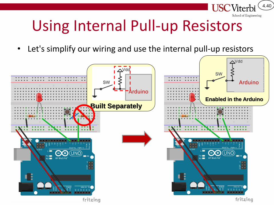
4.40
Using Internal Pull-up Resistors• Let's simplify our wiring and use the internal pull-up resistors
Built Separately
Arduino
Arduino
Enabled in the Arduino
Arduino
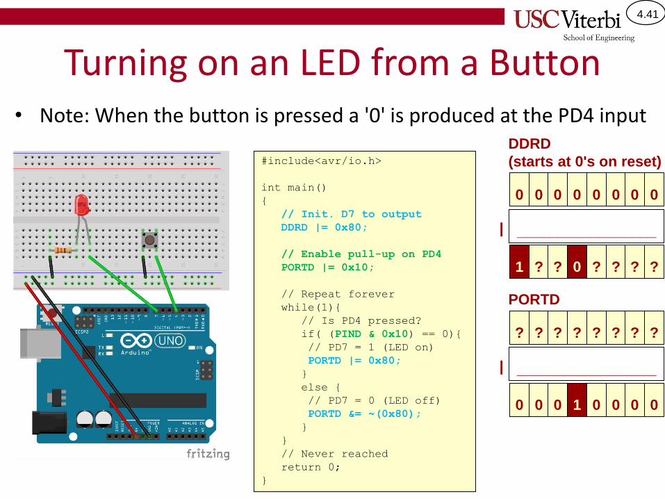
4.41
Turning on an LED from a Button• Note: When the button is pressed a '0' is produced at the PD4 input
?
PORTD
? ? ? ? ? ? ?
| _________________
00 0 1 0 0 00
#include<avr/io.h>
int main()
{
// Init. D7 to output
DDRD |= 0x80;
// Enable pull-up on PD4
PORTD |= 0x10;
// Repeat forever
while(1){
// Is PD4 pressed?
if( (PIND & 0x10) == 0){
// PD7 = 1 (LED on)
PORTD |= 0x80;
}
else {
// PD7 = 0 (LED off)
PORTD &= ~(0x80);
}
}
// Never reached
return 0;
}
0
DDRD
(starts at 0's on reset)
0 0 0 0 0 0 0
| _________________
?? ? 0 ? ? ?1
4.42
FIDDLING WITH STYLE!Using "good" syntax/style when performing logic operations
4.43
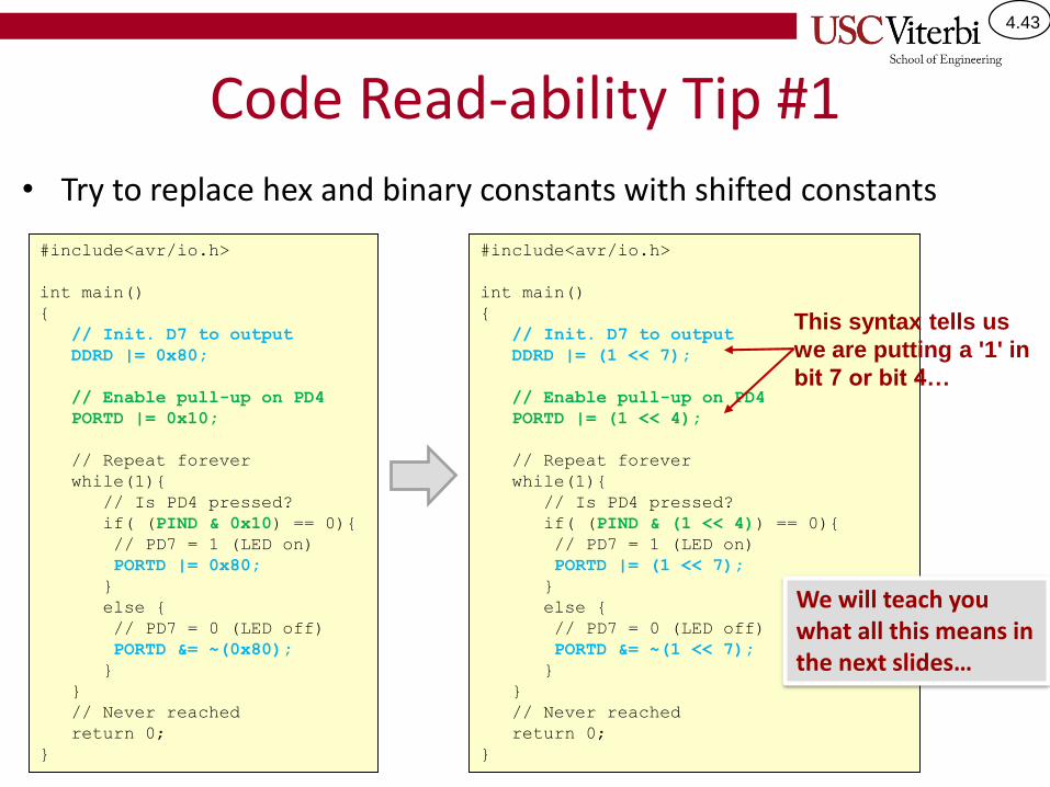
Code Read-ability Tip #1
• Try to replace hex and binary constants with shifted constants
#include<avr/io.h>
int main()
{
// Init. D7 to output
DDRD |= (1 << 7);
// Enable pull-up on PD4
PORTD |= (1 << 4);
// Repeat forever
while(1){
// Is PD4 pressed?
if( (PIND & (1 << 4)) == 0){
// PD7 = 1 (LED on)
PORTD |= (1 << 7);
}
else {
// PD7 = 0 (LED off)
PORTD &= ~(1 << 7);
}
}
// Never reached
return 0;
}
#include<avr/io.h>
int main()
{
// Init. D7 to output
DDRD |= 0x80;
// Enable pull-up on PD4
PORTD |= 0x10;
// Repeat forever
while(1){
// Is PD4 pressed?
if( (PIND & 0x10) == 0){
// PD7 = 1 (LED on)
PORTD |= 0x80;
}
else {
// PD7 = 0 (LED off)
PORTD &= ~(0x80);
}
}
// Never reached
return 0;
}
This syntax tells us
we are putting a '1' in
bit 7 or bit 4…
We will teach you what all this means in the next slides…
4.44
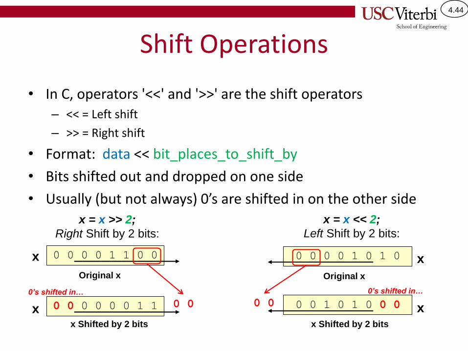
Shift Operations
• In C, operators '<<' and '>>' are the shift operators– << = Left shift
– >> = Right shift
• Format: data << bit_places_to_shift_by
• Bits shifted out and dropped on one side
• Usually (but not always) 0’s are shifted in on the other side
0 0 0 0 0 0 1 1
x = x >> 2;
Right Shift by 2 bits:
Original x
x Shifted by 2 bits
0 0 0 0 1 1 0 0
0 0 0 0 1 0 1 0 0 0
x = x << 2;
Left Shift by 2 bits:
Original x
x Shifted by 2 bits
0 0 0 0 1 0 1 0
0 00’s shifted in… 0’s shifted in…
x
x
x
x
4.45
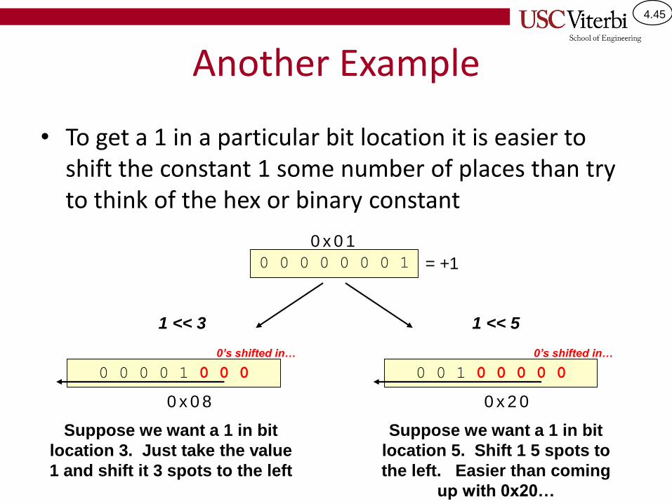
Another Example
• To get a 1 in a particular bit location it is easier to shift the constant 1 some number of places than try to think of the hex or binary constant
0 0 1 0 0 0 0 0
0’s shifted in…
0 0 0 0 0 0 0 1 = +1
0 x 0 1
0 x 2 0
0 0 0 0 1 0 0 0
1 << 3
0’s shifted in…
0 x 0 8
1 << 5
Suppose we want a 1 in bit
location 3. Just take the value
1 and shift it 3 spots to the left
Suppose we want a 1 in bit
location 5. Shift 1 5 spots to
the left. Easier than coming
up with 0x20…
4.46
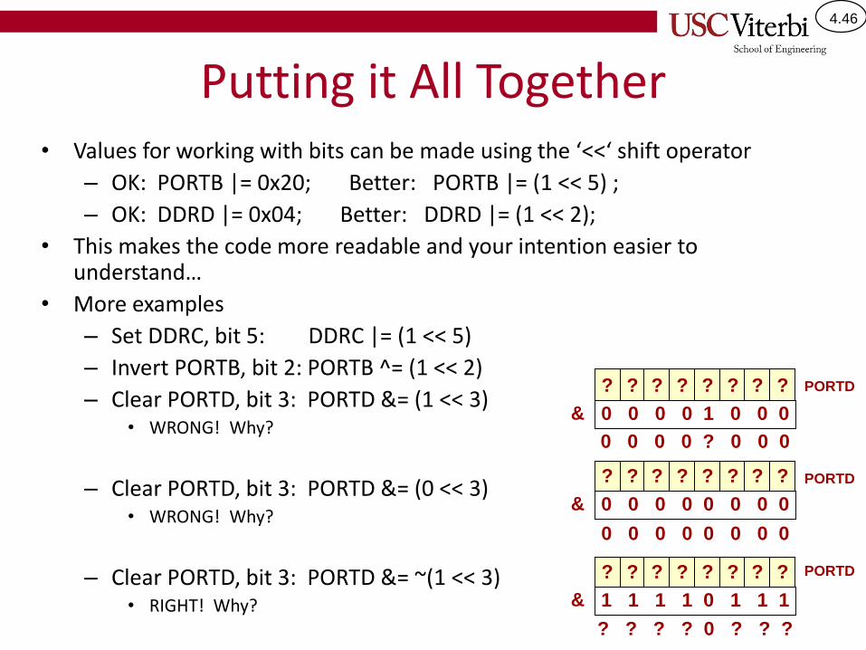
Putting it All Together• Values for working with bits can be made using the ‘<<‘ shift operator
– OK: PORTB |= 0x20; Better: PORTB |= (1 << 5) ;
– OK: DDRD |= 0x04; Better: DDRD |= (1 << 2);
• This makes the code more readable and your intention easier to understand…
• More examples
– Set DDRC, bit 5: DDRC |= (1 << 5)
– Invert PORTB, bit 2: PORTB ^= (1 << 2)
– Clear PORTD, bit 3: PORTD &= (1 << 3) • WRONG! Why?
– Clear PORTD, bit 3: PORTD &= (0 << 3) • WRONG! Why?
– Clear PORTD, bit 3: PORTD &= ~(1 << 3) • RIGHT! Why?
? PORTD? ? ? ? ? ? ?
? PORTD? ? ? ? ? ? ?
? PORTD? ? ? ? ? ? ?
& 0 0 0 0 1 0 0 0
& 0 0 0 0 0 0 0 0
& 1 1 1 1 0 1 1 1
0 0 0 0 ? 0 0 0
0 0 0 0 0 0 0 0
? ? ? ? 0 ? ? ?
4.47
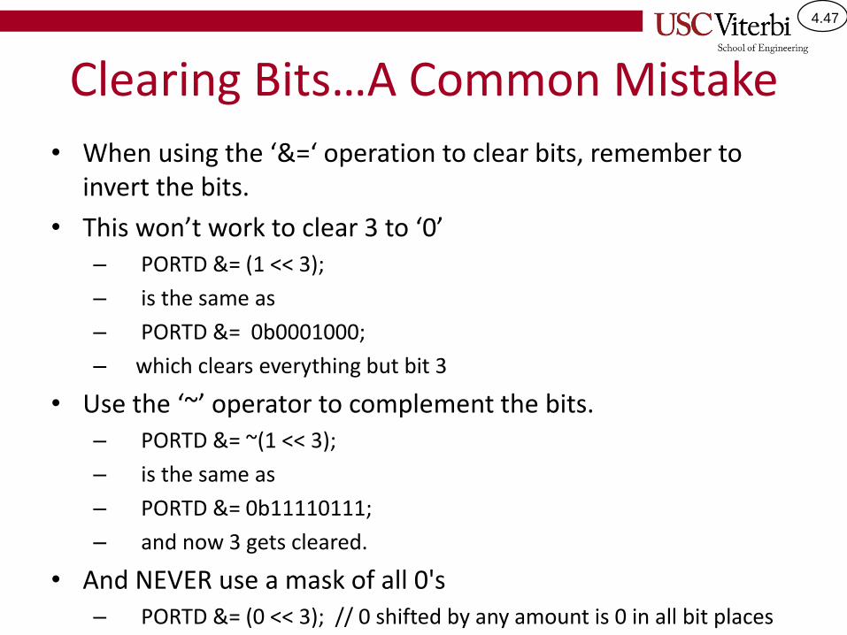
Clearing Bits…A Common Mistake
• When using the ‘&=‘ operation to clear bits, remember to invert the bits.
• This won’t work to clear 3 to ‘0’– PORTD &= (1 << 3);
– is the same as
– PORTD &= 0b0001000;
– which clears everything but bit 3
• Use the ‘~’ operator to complement the bits.– PORTD &= ~(1 << 3);
– is the same as
– PORTD &= 0b11110111;
– and now 3 gets cleared.
• And NEVER use a mask of all 0's– PORTD &= (0 << 3); // 0 shifted by any amount is 0 in all bit places

4.48
Setting/Clearing Multiple bits
• Can combine multiple bits into one defined value– PORTB |= ((1 << 3) | (1 << 4) | (1 << 5));
– is the same as PORTB |= 0b00111000
– PORTB &= ~ ((1 << 3) | (1 << 4) | (1 << 5));
– is the same as PORTB &= 0b11000111;
00001000
00010000
| 00100000
00111000
1 << PB3
1 << PB4
1 << PB5
4.49
DEBOUNCING SWITCHES
4.50
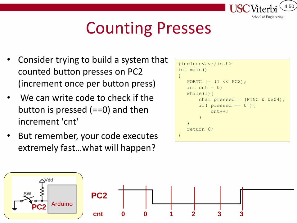
Counting Presses
• Consider trying to build a system that counted button presses on PC2 (increment once per button press)
• We can write code to check if the button is pressed (==0) and then increment 'cnt'
• But remember, your code executes extremely fast…what will happen?
#include<avr/io.h>
int main()
{
PORTC |= (1 << PC2);
int cnt = 0;
while(1){
char pressed = (PINC & 0x04);
if( pressed == 0 ){
cnt++;
}
}
return 0;
}
PC2
cnt 0 0 1 2 3 3
ArduinoPC2
4.51
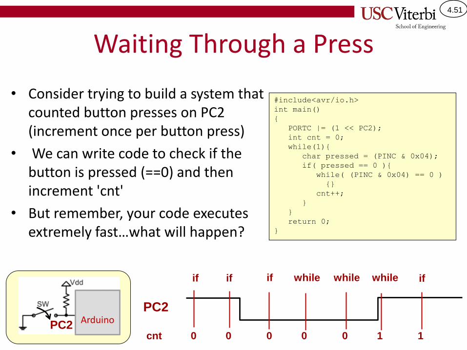
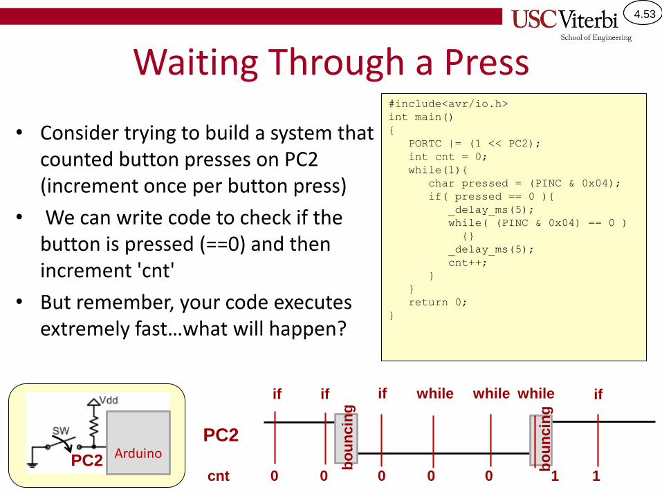
Waiting Through a Press
• Consider trying to build a system that counted button presses on PC2 (increment once per button press)
• We can write code to check if the button is pressed (==0) and then increment 'cnt'
• But remember, your code executes extremely fast…what will happen?
#include<avr/io.h>
int main()
{
PORTC |= (1 << PC2);
int cnt = 0;
while(1){
char pressed = (PINC & 0x04);
if( pressed == 0 ){
while( (PINC & 0x04) == 0 )
{}
cnt++;
}
}
return 0;
}
PC2
cnt 0 0 0 0 0 1 1
ArduinoPC2
if if if while while while if
4.52
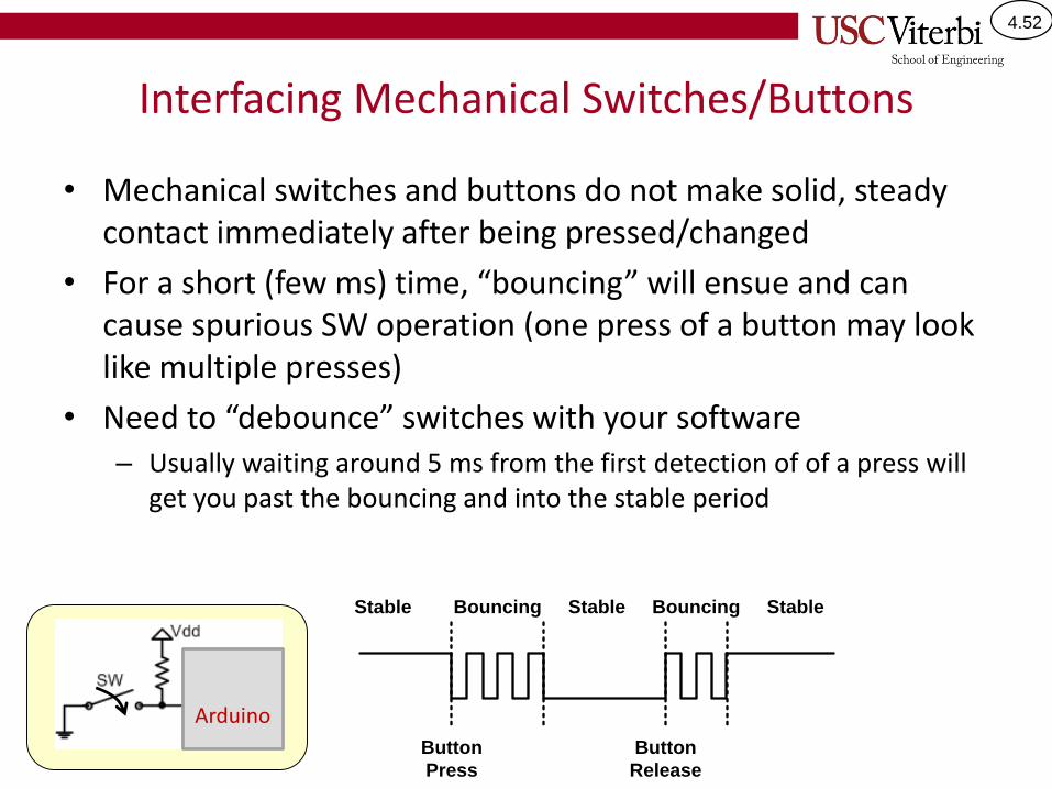
Interfacing Mechanical Switches/Buttons
• Mechanical switches and buttons do not make solid, steady contact immediately after being pressed/changed
• For a short (few ms) time, “bouncing” will ensue and can cause spurious SW operation (one press of a button may look like multiple presses)
• Need to “debounce” switches with your software– Usually waiting around 5 ms from the first detection of of a press will
get you past the bouncing and into the stable period
Stable Bouncing Stable Bouncing Stable
Button
Press
Button
Release
Arduino
4.53
Waiting Through a Press
• Consider trying to build a system that counted button presses on PC2 (increment once per button press)
• We can write code to check if the button is pressed (==0) and then increment 'cnt'
• But remember, your code executes extremely fast…what will happen?
#include<avr/io.h>
int main()
{
PORTC |= (1 << PC2);
int cnt = 0;
while(1){
char pressed = (PINC & 0x04);
if( pressed == 0 ){
_delay_ms(5);
while( (PINC & 0x04) == 0 )
{}
_delay_ms(5);
cnt++;
}
}
return 0;
}
PC2
cnt 0 0 0 0 0 1 1
ArduinoPC2
if if if while while while if
bo
un
cin
g
bo
un
cin
g
4.54
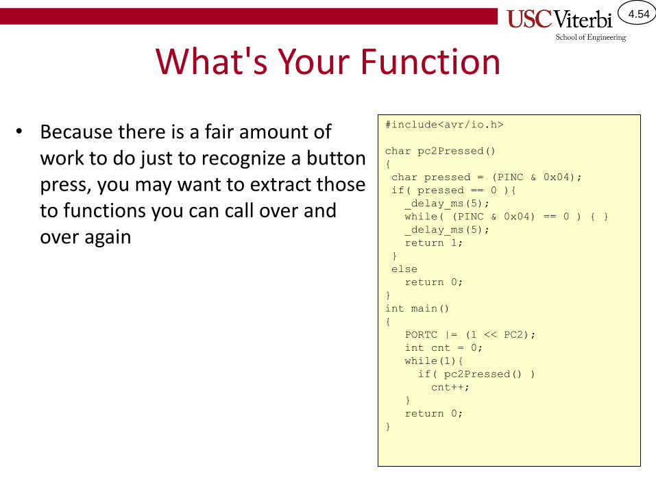
What's Your Function
• Because there is a fair amount of work to do just to recognize a button press, you may want to extract those to functions you can call over and over again
#include<avr/io.h>
char pc2Pressed()
{
char pressed = (PINC & 0x04);
if( pressed == 0 ){
_delay_ms(5);
while( (PINC & 0x04) == 0 ) { }
_delay_ms(5);
return 1;
}
else
return 0;
}
int main()
{
PORTC |= (1 << PC2);
int cnt = 0;
while(1){
if( pc2Pressed() )
cnt++;
}
return 0;
}
4.55
SUMMARY AND EXERCISES
4.56
Exercise 1
• We want to use Group C (Port C) bit 5 as an output. Show how you should initialize your program then write a statement to turn the output 'ON' to 5V.
4.57
Exercise 2
• Now turn write a statement to turn that same output ‘OFF’ (i.e. to output 0V)
4.58
Exercise 3
• We want to use Group B (Port B) bit 3 as an input connected to a switch. You have no separate resistors available to you. Show how you should initialize your program and then write an if statement to check if the input voltage is HIGH (5V).
4.59
Common Mistakes
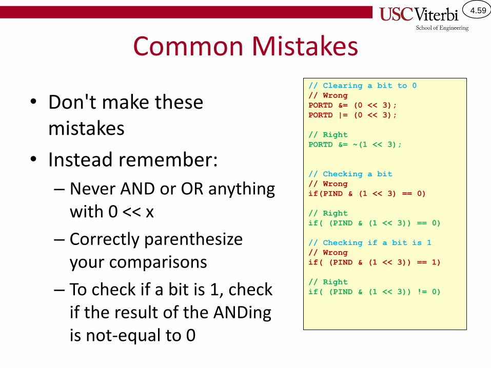
• Don't make these mistakes
• Instead remember:
– Never AND or OR anything with 0 << x
– Correctly parenthesize your comparisons
– To check if a bit is 1, check if the result of the ANDing is not-equal to 0
// Clearing a bit to 0
// Wrong
PORTD &= (0 << 3);
PORTD |= (0 << 3);
// Right
PORTD &= ~(1 << 3);
// Checking a bit
// Wrong
if(PIND & (1 << 3) == 0)
// Right
if( (PIND & (1 << 3)) == 0)
// Checking if a bit is 1
// Wrong
if( (PIND & (1 << 3)) == 1)
// Right
if( (PIND & (1 << 3)) != 0)
4.60
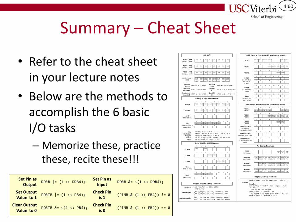
Summary – Cheat Sheet
• Refer to the cheat sheet in your lecture notes
• Below are the methods to accomplish the 6 basic I/O tasks
– Memorize these, practice these, recite these!!!
Set Pin as Output
DDRB |= (1 << DDB4);
Set Output Value to 1
PORTB |= (1 << PB4);
Clear Output Value to 0
PORTB &= ~(1 << PB4);
Set Pin as Input
DDRB &= ~(1 << DDB4);
Check Pin is 1
(PINB & (1 << PB4)) != 0
Check Pin is 0
(PINB & (1 << PB4)) == 0
PB6PORTB / PINB(output / input)
PB7 PB4PB5 PB2PB3 PB0PB1
PORTC / PINC(output / input)
PC6PC7 PC4PC5 PC2PC3 PC0PC1
PD6PORTD / PIND(output / input)
PD7 PD4PD5 PD2PD3 PD0PD1
DDB6DDC6DDD6
DDB7DDC7DDD7
DDB4DDC4DDD4
DDB5DDC5DDD5
DDB2DDC2DDD2
DDB3DDC3DDD3
DDB0DDC0DDD0
DDB1DDC1DDD1
DDRB / DDRC / DDRD
REFS0REFS1 unusedADLAR MUX2MUX3 MUX0MUX1ADMUX
67 45 23 01
ADSCADEN ADIFADATE ADPS2ADIE ADPS0ADPS1ADCSRA
67 45 23 01
ADCH(8-bit ADC res.)
67 45 23 01
ADC(10-bit ADC res. /
16-bit value)
00 00 00
1415 1213 1011 89
67 45 23 01
OCR1A(16-bit value)Timer MAX
or PWM
1415 1213 1011 89
67 45 23 01
COM1A0COM1A1 COM1B0COM1B1 WGM10WGM11TCCR1A
67 45 23 01
WGM13 CS12WGM12 CS10CS11TCCR1B
67 45 23 01
OCIE1B OCIE1ATIMSK1
67 45 23 01
TCNT1(16-bit current count value)
1415 1213 1011 89
67 45 23 01
OCR0A / OCR2A(8-bit value)
Timer MAX or PWM
67 45 23 01
COM0A0COM2A0
COM0A1COM2A1
COM0B0COM2B0
COM0B1COM2B1
WGM00WGM20
WGM01WGM21
TCCR0ATCCR2A
67 45 23 01
WGM03WGM23
CS02CS22
WGM02WGM22
CS00CS20
CS01CS21
TCCR0BTCCR2B
67 45 23 01
OCIE0BOCIE2B
OCIE0AOCIE2A
TIMSK0TIMSK2
67 45 23 01
TCNT0 / TCNT2(8-bit current count
value)
67 45 23 01
OCR1B(16-bit value)
PWM
1415 1213 1011 89
67 45 23 01
OCR0B / OCR2B(8-bit value) for PWM
67 45 23 01
UCSR0A RXC0 UDRE0
UCSR0B RXEN0 TXEN0
UCSR0C UCSZ01 UCSZ00
UDR0(RX & TX Data)
67 45 23 01
UBRR0(Baud Rate)
00 00
1415 1213 1011 89
67 45 23 01
Digital I/O
Set Pin as Output
DDRB |= (1 << DDB4);
Set Output Value to 1
PORTB |= (1 << PB4);
Clear Output Value to 0
PORTB &= ~(1 << PB4);
Set Pin as Input
DDRB &= ~(1 << DDB4);
Check Pin is 1
(PINB & (1 << PB4)) != 0
Check Pin is 0
(PINB & (1 << PB4)) == 0
Analog to Digital Conversion
After initialization,
start, poll, capture
result
ADCSRA |= (1 << ADSC);while( (ADCSRA & (1 << ADSC)) != 0 ) { }unsigned char result = ADCH;// if 10-bit result (ADLAR = 0) use this// unsigned int result = ADC;
Serial (UART / RS-232) Comm.
PCICRInt. Enables
PCIE2(D)
PCIE0(B)
PCIE1(C)
PCMSK0(for Port B)
PCINT6(PB6)
PCINT7(PB7)
PCINT4(PB4)
PCINT5(PB5)
PCINT2(PB2)
PCINT3(PB3)
PCINT0(PB0)
PCINT1(PB1)
PCMSK1(for Port C)
PCMSK2(for Port D)
PCINT14(PC6)
PCINT12(PC4)
PCINT13(PC5)
PCINT10(PC2)
PCINT11(PC3)
PCINT8(PC0)
PCINT9(PC1)
PCINT22(PD6)
PCINT23(PD7)
PCINT20(PD4)
PCINT21(PD5)
PCINT18(PD2)
PCINT19(PD3)
PCINT16(PD0)
PCINT17(PD1)
Pin Change Interrupts67 45 23 01
67 45 23 01
67 45 23 01
16-bit Timer and Pulse Width Modulation (PWM)
8-bit Timers and Pulse Width Modulation (PWM)
Helpful C-Library Functions
<stdio.h>
snprintf(char* buf, int max, char* frmt, ...);
Example:char buf[9]; // Val= max 4-digits + nullint val; // val set to some integersnprintf(buf, 5, Val=%d val);// to ensure fixed space (num. digits) for valsnprintf(buf, 5, Val=%4d val);
Helpful Arduino Library Functions
All register and bit position definitions
<avr/io.h>
_delay_ms(10); // delay 10 milli(m)-sec_delay_us(10); // delay 10 micro(u)-sec
<util/delay.h>
sei(); // turn on global interrupt enablecli(); // turn off global interrupt enable
<avr/interrupt.h>