EduCake LED Matrix -1- EduCake LED Matrix 1. Introduction to LED Matrix In the previous chapters,...
28
86Duino www.86duino.com -1- EduCake LED Matrix 1. Introduction to LED Matrix In the previous chapters, we talked about the 86Duino EduCake’s digital and analog output capabilities and used them to control a small number of LED, where each LED is attached to one of the digital I/O pin on the EduCake. Dedicating a separate digital I/O pin to control one LED is not a good approach, when you have to control large number of LEDs, such as the 8x8 LED matrix with 64 LEDs. There are limited number of digital I/O pin on the EduCake. In addition to reserving some I/O pins to serve other function, there is not sufficient number of pins to control 64 LEDs using the 1 I/O pin to 1 LED option. In this chapter, instead of allocating one I/O pin to control each individual LED, we will talk about different approach to control large number of LEDs within an LED matrix. LED matrix can be used to display scrolling text, flashing marquee, image and variety of other usage.
Transcript of EduCake LED Matrix -1- EduCake LED Matrix 1. Introduction to LED Matrix In the previous chapters,...
86Duino www.86duino.com
-1-
EduCake LED Matrix
1. Introduction to LED Matrix
In the previous chapters, we talked about the 86Duino EduCake’s digital and
analog output capabilities and used them to control a small number of LED, where
each LED is attached to one of the digital I/O pin on the EduCake. Dedicating a
separate digital I/O pin to control one LED is not a good approach, when you have to
control large number of LEDs, such as the 8x8 LED matrix with 64 LEDs. There are
limited number of digital I/O pin on the EduCake. In addition to reserving some I/O
pins to serve other function, there is not sufficient number of pins to control 64 LEDs
using the 1 I/O pin to 1 LED option.
In this chapter, instead of allocating one I/O pin to control each individual LED, we
will talk about different approach to control large number of LEDs within an LED
matrix.
LED matrix can be used to display scrolling text, flashing marquee, image and
variety of other usage.
86Duino www.86duino.com
-2-
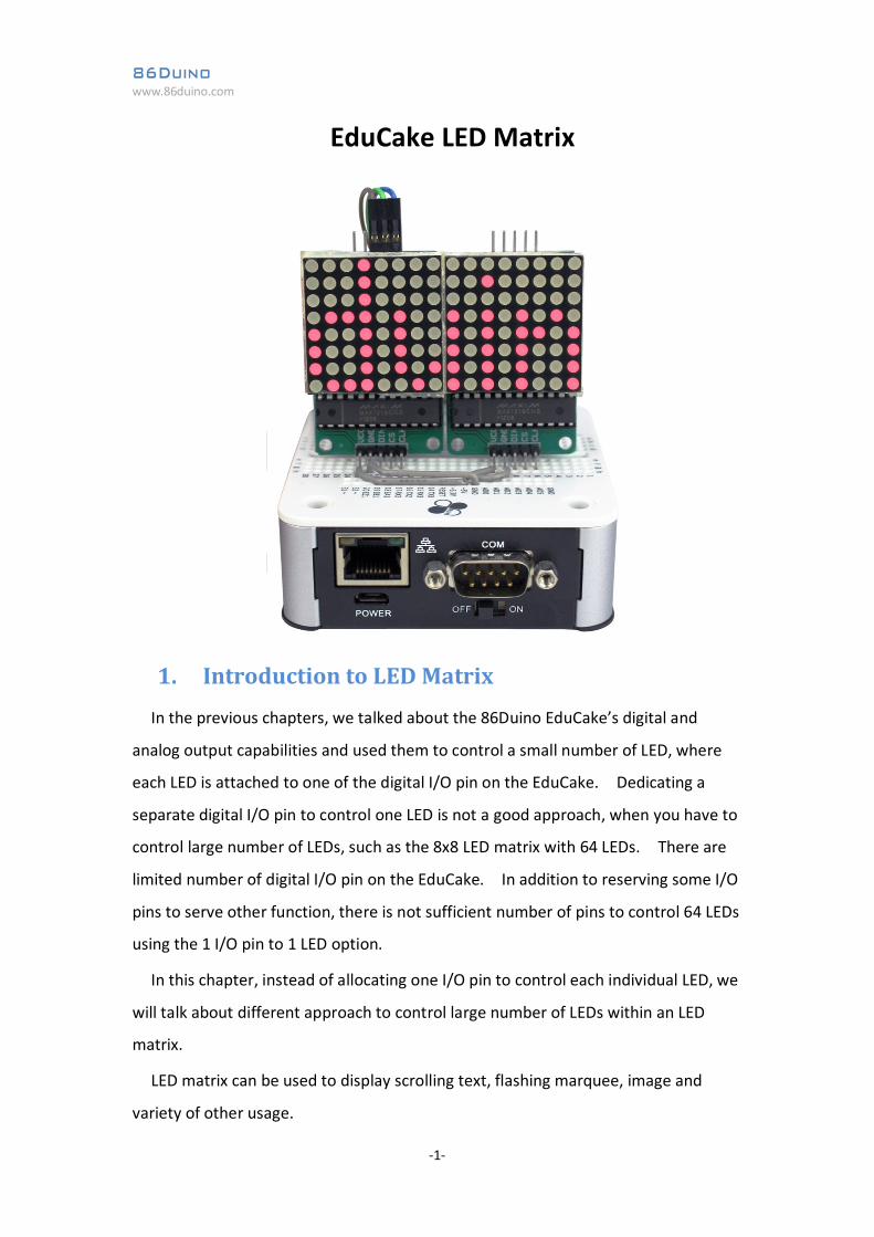
While there are large variety of LED matrix in the market, in different size and
configuration, they are based on two common wiring implementation,
common-anode and common-cathode, where all of the LEDs’ anode in a row (or
column) are wired together and all of the LEDs’ cathode in a column (or row) are
wired together, as shown in figure-1 and figure-2.
Figure-1: LED Matrix with common Anode
Figure-2: LED Matrix with common Cathode
86Duino www.86duino.com
-3-
As you can see from figure-1 and figure-2 above, for a monochrome (single color)
LED matrix, whether it’s using common-anode or common-cathode wiring method,
the LED matrix behave pretty much the same and can be controlled using similar
programming logic. When working with multi-color LED, programming logic for
common-anode is different from common-cathode wiring method.
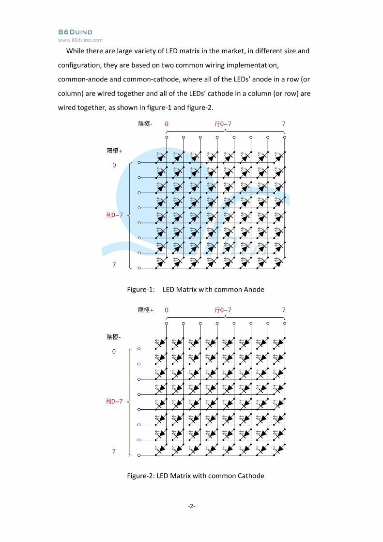
When working with LED matrix, whether it’s common Anode or Cathode wiring,
it’s not possible to turn multiple LEDs on different rows and columns ON and keep
them ON at the same time. To create the visual effect where all designated LEDs
appear to be on at the same time, a vision persistence method is used. This is a
scanning method where the controller turns ON designated LEDs in a row (or
column), one row (or one column) after next, cycling through all rows (or columns)
to turn on designated LEDs, at a rate that is fast enough to trick human eyes into
seeing the designated LEDs appear to be on at the same time, as shown in figure-3.
Figure-3: Scan method to turn LEDs on row by row
LED matrix can be used to display scrolling text, flashing marquee, image and
variety of other usage.
The scan method greatly reduced the number of I/O pins needed to control the
LED Matrix. Using the 86Duino EduCake as the controller, only 16 I/O pins are
needed, along with some resistors, to control the above 8x8 LED matrix which has 64
LEDs.
While it’s possible to control large number of LEDs with relatively small number of
I/O pins using LED matrix, it increase the program’s complexity. With the need to
86Duino www.86duino.com
-4-
control multiple group of LED matrix, the limited number of digital I/O pins is a
challenging problem to overcome.
Fortunately, there are ICs in the market, designed specifically to control LED
matrix. With simple codes, these ICs can be controlled to deliver LED matrix scanning
function and intended visual effect.
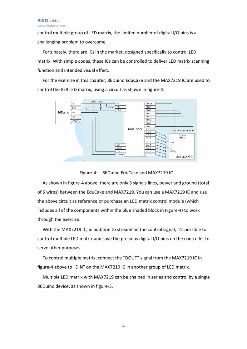
For the exercise in this chapter, 86Duino EduCake and the MAX7219 IC are used to
control the 8x8 LED matrix, using a circuit as shown in figure-4.
Figure-4: 86Duino EduCake and MAX7219 IC
As shown in figure-4 above, there are only 3 signals lines, power and ground (total
of 5 wires) between the EduCake and MAX7219. You can use a MAX7219 IC and use
the above circuit as reference or purchase an LED matrix control module (which
includes all of the components within the blue shaded block in Figure-4) to work
through the exercise.
With the MAX7219 IC, in addition to streamline the control signal, it’s possible to
control multiple LED matrix and save the precious digital I/O pins on the controller to
serve other purposes.
To control multiple matrix, connect the “DOUT” signal from the MAX7219 IC in
figure-4 above to “DIN” on the MAX7219 IC in another group of LED matrix.
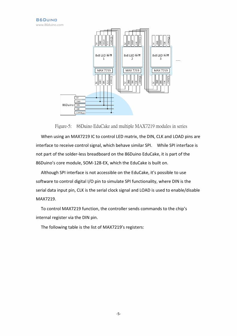
Multiple LED matrix with MAX7219 can be chained in series and control by a single
86Duino device, as shown in figure-5.
86Duino www.86duino.com
-5-
Figure-5: 86Duino EduCake and multiple MAX7219 modules in series
When using an MAX7219 IC to control LED matrix, the DIN, CLK and LOAD pins are
interface to receive control signal, which behave similar SPI. While SPI interface is
not part of the solder-less breadboard on the 86Duino EduCake, it is part of the
86Duino’s core module, SOM-128-EX, which the EduCake is built on.
Although SPI interface is not accessible on the EduCake, it’s possible to use
software to control digital I/O pin to simulate SPI functionality, where DIN is the
serial data input pin, CLK is the serial clock signal and LOAD is used to enable/disable
MAX7219.
To control MAX7219 function, the controller sends commands to the chip’s
internal register via the DIN pin.
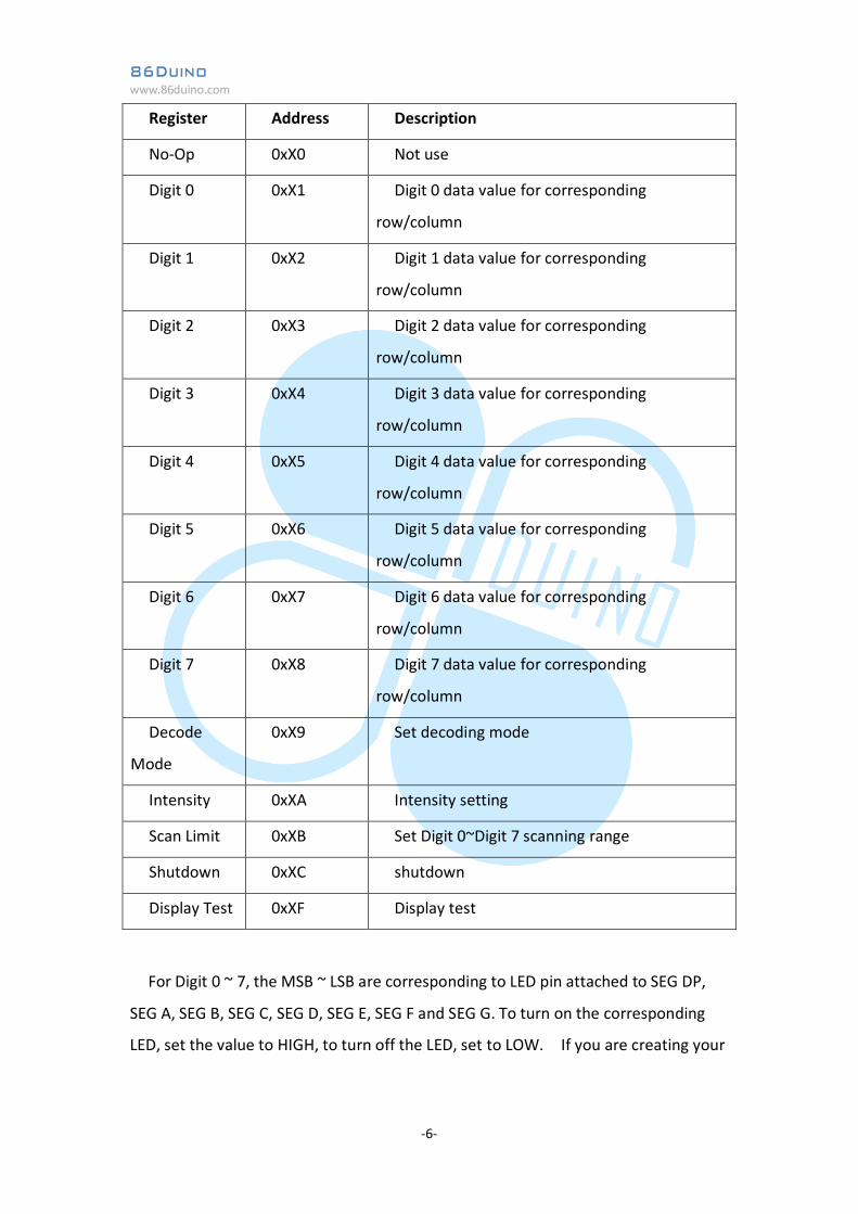
The following table is the list of MAX7219’s registers:
86Duino www.86duino.com
-6-
Register Address Description
No-Op 0xX0 Not use
Digit 0 0xX1 Digit 0 data value for corresponding
row/column
Digit 1 0xX2 Digit 1 data value for corresponding
row/column
Digit 2 0xX3 Digit 2 data value for corresponding
row/column
Digit 3 0xX4 Digit 3 data value for corresponding
row/column
Digit 4 0xX5 Digit 4 data value for corresponding
row/column
Digit 5 0xX6 Digit 5 data value for corresponding
row/column
Digit 6 0xX7 Digit 6 data value for corresponding
row/column
Digit 7 0xX8 Digit 7 data value for corresponding
row/column
Decode
Mode
0xX9 Set decoding mode
Intensity 0xXA Intensity setting
Scan Limit 0xXB Set Digit 0~Digit 7 scanning range
Shutdown 0xXC shutdown
Display Test 0xXF Display test
For Digit 0 ~ 7, the MSB ~ LSB are corresponding to LED pin attached to SEG DP,
SEG A, SEG B, SEG C, SEG D, SEG E, SEG F and SEG G. To turn on the corresponding
LED, set the value to HIGH, to turn off the LED, set to LOW. If you are creating your
86Duino www.86duino.com
-7-
own LED matrix using the MAX7219 chip, pay attention to the pin and corresponding
register.
In addition to controlling an 8x8 LED matrix, the MAX7219 chip can be used to
control 8 units of 7-segments LED display (each 7-segments display has 8 LEDs,
commonly referred to as: DP, A, B, C, D, E, F and G). After learning how to control
LED matrix using MAX7219, you can adopt the same principle to control a series of
7-segments LED display.
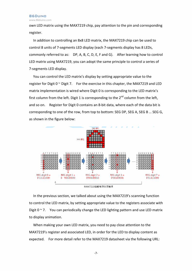
You can control the LED matrix’s display by setting appropriate value to the
register for Digit 0 ~ Digit 7. For the exercise in this chapter, the MAX7219 and LED
matrix implementation is wired where Digit 0 is corresponding to the LED matrix’s
first column from the left. Digit 1 is corresponding to the 2nd column from the left,
and so on. Register for Digit 0 contains an 8-bit data, where each of the data bit is
corresponding to one of the row, from top to bottom: SEG DP, SEG A, SEG B … SEG G,
as shown in the figure below:
In the previous section, we talked about using the MAX7219’s scanning function
to control the LED matrix, by setting appropriate value to the registers associate with
Digit 0 ~ 7. You can periodically change the LED lighting pattern and use LED matrix
to display animation.
When making your own LED matrix, you need to pay close attention to the
MAX7219’s register and associated LED, in order for the LED to display content as
expected. For more detail refer to the MAX7219 datasheet via the following URL:
86Duino www.86duino.com
-8-
http://datasheets.maximintegrated.com/en/ds/MAX7219-MAX7221.pdf
In the next section, we will work through different sample exercises to control LED
matrix using the MAX7219 chip, as discussed in this section.
86Duino www.86duino.com
-9-
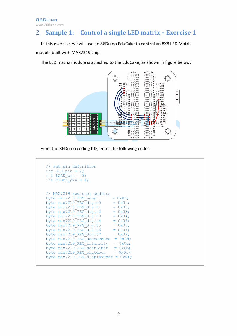
2. Sample 1: Control a single LED matrix – Exercise 1 In this exercise, we will use an 86Duino EduCake to control an 8X8 LED Matrix
module built with MAX7219 chip.
The LED matrix module is attached to the EduCake, as shown in figure below:
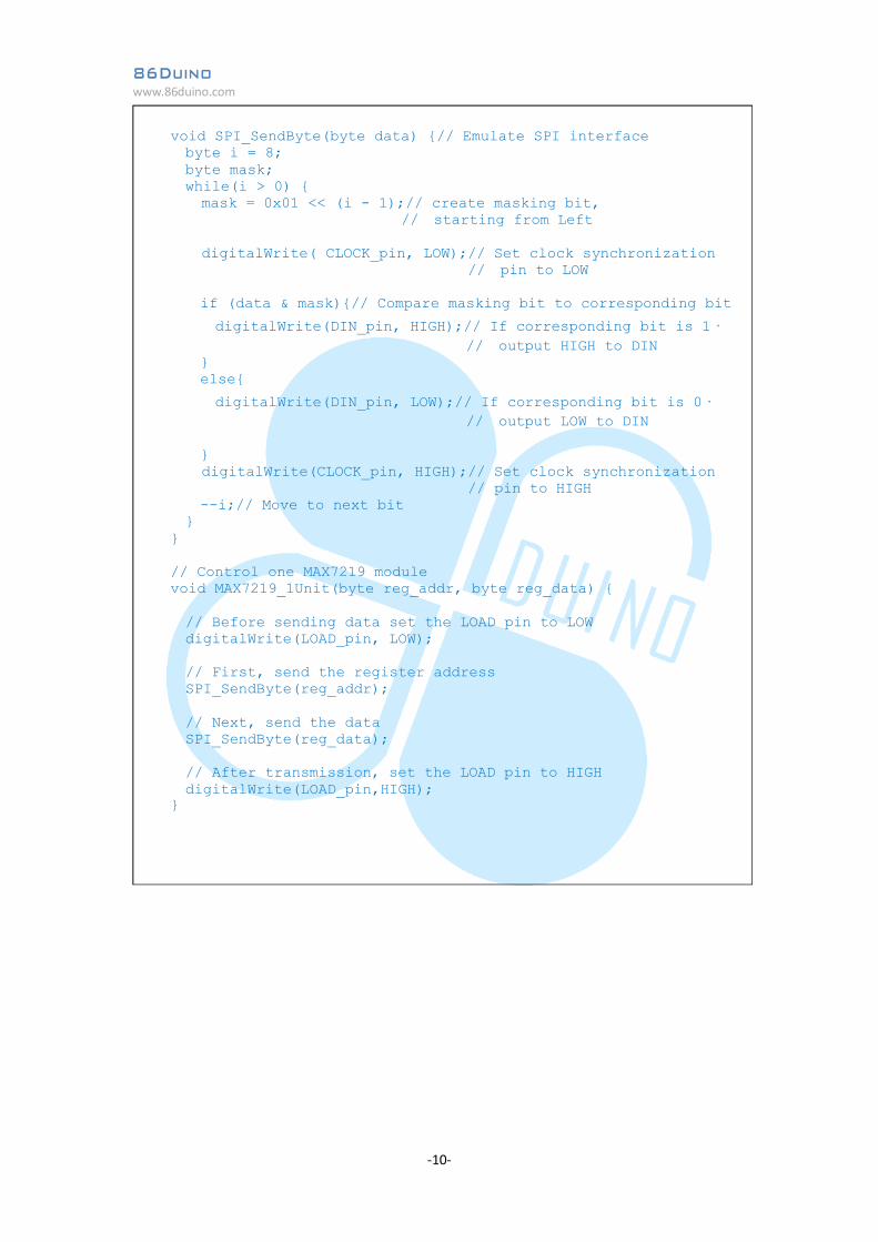
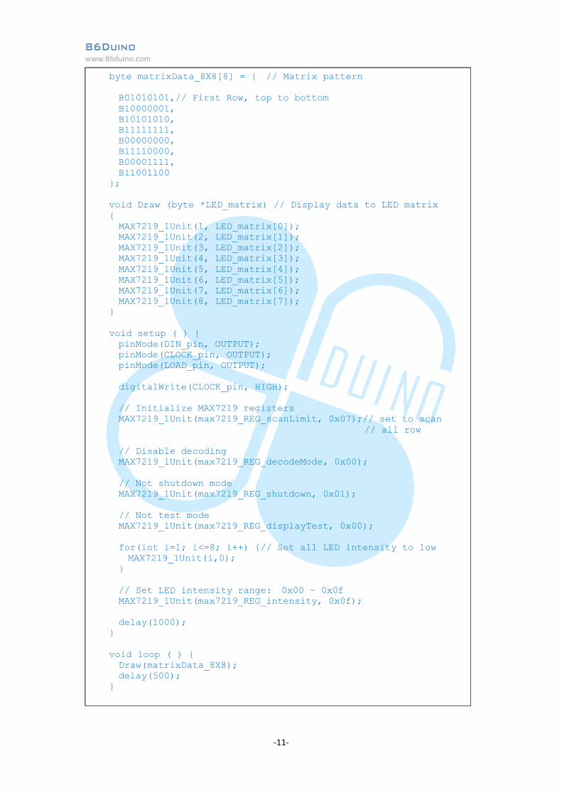
From the 86Duino coding IDE, enter the following codes:
// set pin definition int DIN_pin = 2; int LOAD_pin = 3; int CLOCK_pin = 4; // MAX7219 register address byte max7219_REG_noop = 0x00; byte max7219_REG_digit0 = 0x01; byte max7219_REG_digit1 = 0x02; byte max7219_REG_digit2 = 0x03; byte max7219_REG_digit3 = 0x04; byte max7219_REG_digit4 = 0x05; byte max7219_REG_digit5 = 0x06; byte max7219_REG_digit6 = 0x07; byte max7219_REG_digit7 = 0x08; byte max7219_REG_decodeMode = 0x09; byte max7219_REG_intensity = 0x0a; byte max7219_REG_scanLimit = 0x0b; byte max7219_REG_shutdown = 0x0c; byte max7219_REG_displayTest = 0x0f;
86Duino www.86duino.com
-10-
void SPI_SendByte(byte data) {// Emulate SPI interface byte i = 8; byte mask; while(i > 0) {
mask = 0x01 << (i - 1);// create masking bit, // starting from Left digitalWrite( CLOCK_pin, LOW);// Set clock synchronization // pin to LOW
if (data & mask){// Compare masking bit to corresponding bit
digitalWrite(DIN_pin, HIGH);// If corresponding bit is 1, // output HIGH to DIN } else{
digitalWrite(DIN_pin, LOW);// If corresponding bit is 0, // output LOW to DIN }
digitalWrite(CLOCK_pin, HIGH);// Set clock synchronization // pin to HIGH
--i;// Move to next bit } } // Control one MAX7219 module void MAX7219_1Unit(byte reg_addr, byte reg_data) { // Before sending data set the LOAD pin to LOW digitalWrite(LOAD_pin, LOW); // First, send the register address SPI_SendByte(reg_addr); // Next, send the data SPI_SendByte(reg_data); // After transmission, set the LOAD pin to HIGH digitalWrite(LOAD_pin,HIGH); }
86Duino www.86duino.com
-11-
byte matrixData_8X8[8] = { // Matrix pattern B01010101,// First Row, top to bottom B10000001, B10101010, B11111111, B00000000, B11110000, B00001111, B11001100 }; void Draw (byte *LED_matrix) // Display data to LED matrix { MAX7219_1Unit(1, LED_matrix[0]); MAX7219_1Unit(2, LED_matrix[1]); MAX7219_1Unit(3, LED_matrix[2]); MAX7219_1Unit(4, LED_matrix[3]); MAX7219_1Unit(5, LED_matrix[4]); MAX7219_1Unit(6, LED_matrix[5]); MAX7219_1Unit(7, LED_matrix[6]); MAX7219_1Unit(8, LED_matrix[7]); } void setup ( ) { pinMode(DIN_pin, OUTPUT); pinMode(CLOCK_pin, OUTPUT); pinMode(LOAD_pin, OUTPUT); digitalWrite(CLOCK_pin, HIGH); // Initialize MAX7219 registers MAX7219_1Unit(max7219_REG_scanLimit, 0x07);// set to scan // all row // Disable decoding MAX7219_1Unit(max7219_REG_decodeMode, 0x00); // Not shutdown mode MAX7219_1Unit(max7219_REG_shutdown, 0x01); // Not test mode MAX7219_1Unit(max7219_REG_displayTest, 0x00); for(int i=1; i<=8; i++) {// Set all LED intensity to low MAX7219_1Unit(i,0); } // Set LED intensity range: 0x00 ~ 0x0f MAX7219_1Unit(max7219_REG_intensity, 0x0f); delay(1000); } void loop ( ) { Draw(matrixData_8X8); delay(500); }
86Duino www.86duino.com
-12-
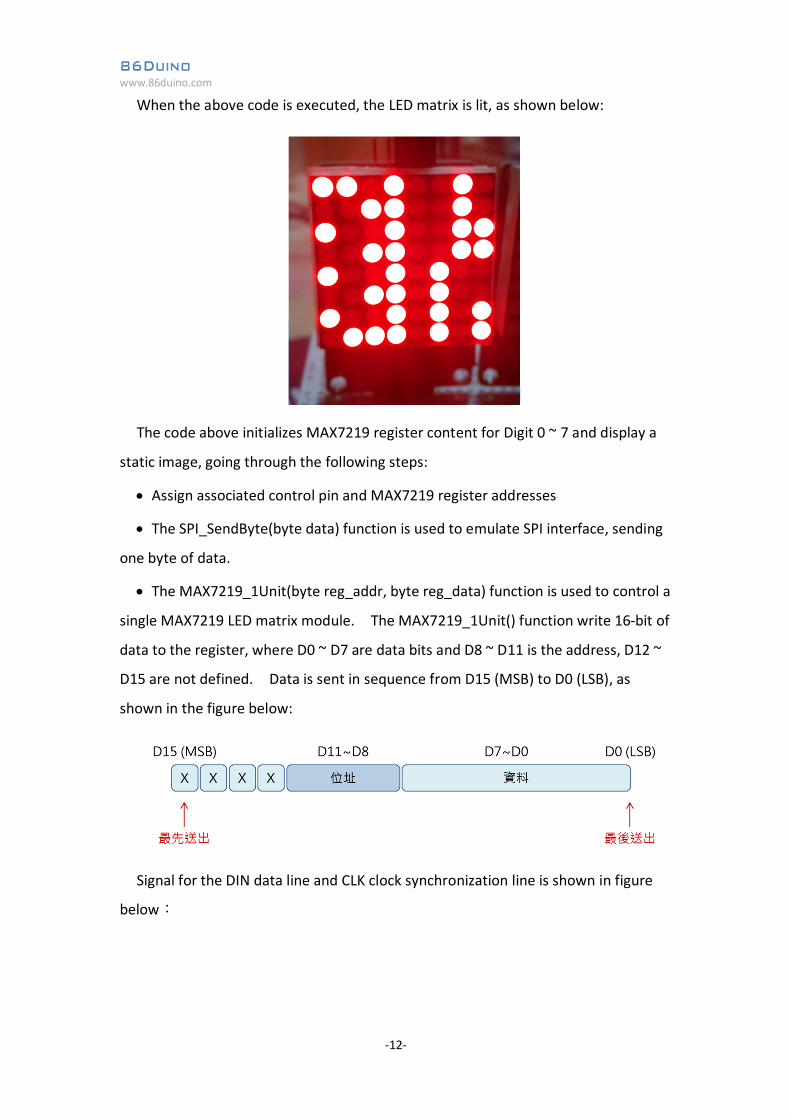
When the above code is executed, the LED matrix is lit, as shown below:
The code above initializes MAX7219 register content for Digit 0 ~ 7 and display a
static image, going through the following steps:
Assign associated control pin and MAX7219 register addresses
The SPI_SendByte(byte data) function is used to emulate SPI interface, sending
one byte of data.
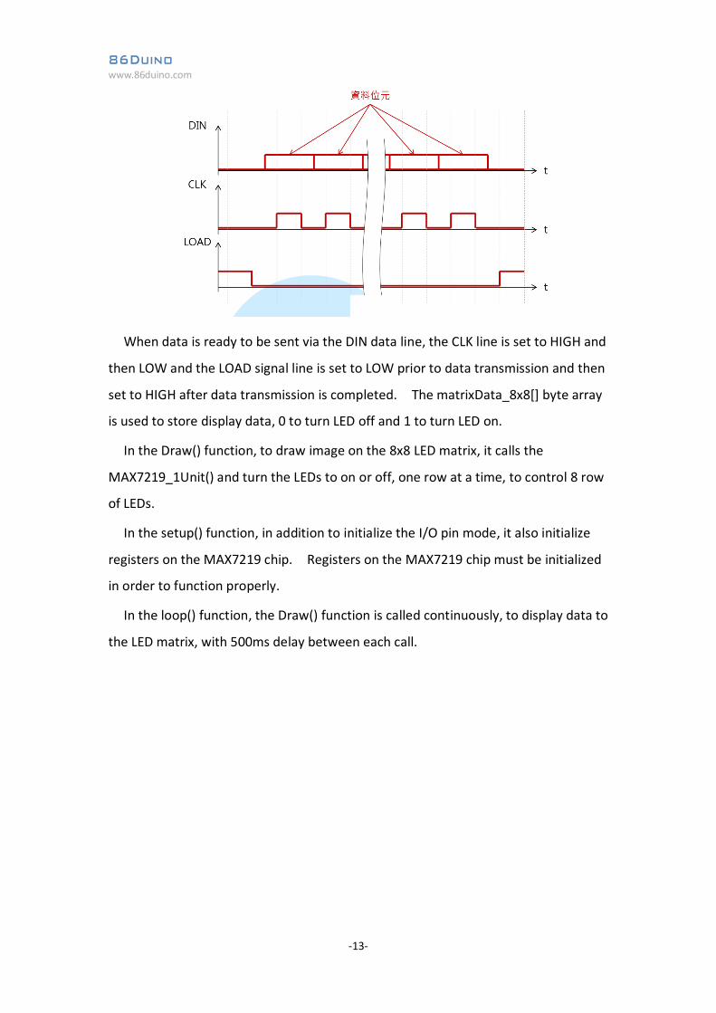
The MAX7219_1Unit(byte reg_addr, byte reg_data) function is used to control a
single MAX7219 LED matrix module. The MAX7219_1Unit() function write 16-bit of
data to the register, where D0 ~ D7 are data bits and D8 ~ D11 is the address, D12 ~
D15 are not defined. Data is sent in sequence from D15 (MSB) to D0 (LSB), as
shown in the figure below:
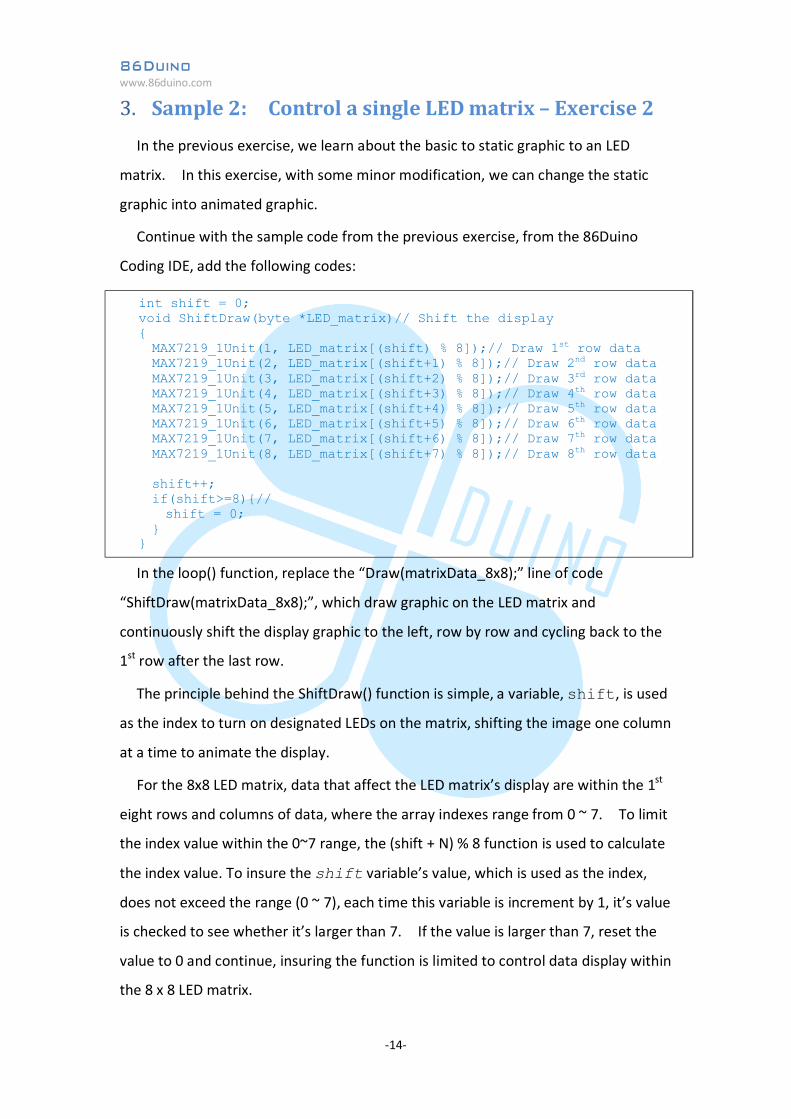
Signal for the DIN data line and CLK clock synchronization line is shown in figure
below:
86Duino www.86duino.com
-13-
When data is ready to be sent via the DIN data line, the CLK line is set to HIGH and
then LOW and the LOAD signal line is set to LOW prior to data transmission and then
set to HIGH after data transmission is completed. The matrixData_8x8[] byte array
is used to store display data, 0 to turn LED off and 1 to turn LED on.
In the Draw() function, to draw image on the 8x8 LED matrix, it calls the
MAX7219_1Unit() and turn the LEDs to on or off, one row at a time, to control 8 row
of LEDs.
In the setup() function, in addition to initialize the I/O pin mode, it also initialize
registers on the MAX7219 chip. Registers on the MAX7219 chip must be initialized
in order to function properly.
In the loop() function, the Draw() function is called continuously, to display data to
the LED matrix, with 500ms delay between each call.
86Duino www.86duino.com
-14-
3. Sample 2: Control a single LED matrix – Exercise 2 In the previous exercise, we learn about the basic to static graphic to an LED
matrix. In this exercise, with some minor modification, we can change the static
graphic into animated graphic.
Continue with the sample code from the previous exercise, from the 86Duino
Coding IDE, add the following codes:
In the loop() function, replace the “Draw(matrixData_8x8);” line of code
“ShiftDraw(matrixData_8x8);”, which draw graphic on the LED matrix and
continuously shift the display graphic to the left, row by row and cycling back to the
1st row after the last row.
The principle behind the ShiftDraw() function is simple, a variable, shift, is used
as the index to turn on designated LEDs on the matrix, shifting the image one column
at a time to animate the display.
For the 8x8 LED matrix, data that affect the LED matrix’s display are within the 1st
eight rows and columns of data, where the array indexes range from 0 ~ 7. To limit
the index value within the 0~7 range, the (shift + N) % 8 function is used to calculate
the index value. To insure the shift variable’s value, which is used as the index,
does not exceed the range (0 ~ 7), each time this variable is increment by 1, it’s value
is checked to see whether it’s larger than 7. If the value is larger than 7, reset the
value to 0 and continue, insuring the function is limited to control data display within
the 8 x 8 LED matrix.
int shift = 0; void ShiftDraw(byte *LED_matrix)// Shift the display { MAX7219_1Unit(1, LED_matrix[(shift) % 8]);// Draw 1st row data MAX7219_1Unit(2, LED_matrix[(shift+1) % 8]);// Draw 2nd row data MAX7219_1Unit(3, LED_matrix[(shift+2) % 8]);// Draw 3rd row data MAX7219_1Unit(4, LED_matrix[(shift+3) % 8]);// Draw 4th row data MAX7219_1Unit(5, LED_matrix[(shift+4) % 8]);// Draw 5th row data MAX7219_1Unit(6, LED_matrix[(shift+5) % 8]);// Draw 6th row data MAX7219_1Unit(7, LED_matrix[(shift+6) % 8]);// Draw 7th row data MAX7219_1Unit(8, LED_matrix[(shift+7) % 8]);// Draw 8th row data shift++; if(shift>=8){// shift = 0; } }
86Duino www.86duino.com
-15-
4. Sample 3: Control a single LED matrix – Exercise 3 For this exercise, using the same electronic circuit, we will add additional function
to the project from the previous exercise.
Continue with the code from the previous exercise, from the 86Duino Coding IDE,
add the following codes:
// 0 byte matrixData_num_0[8] = {// Display data_0 for LED matrix B00000000,// row 1, top to bottom B01111110, B10010001, B10001001, B10001001, B10000101, B01111110, B00000000 }; // 1 byte matrixData_num_1[8] = {// Display data_1 for LED matrix B00000000,// row 1, top to bottom B00000000, B10000000, B10000010, B11111111, B10000000, B00000000, B00000000 }; // 2 byte matrixData_num_2[8] = {// Display data_2 for LED matrix B00000000,// row 1, top to bottom B10000110, B10000001, B11000001, B10100001, B10010001, B10001110, B00000000 };
86Duino www.86duino.com
-16-
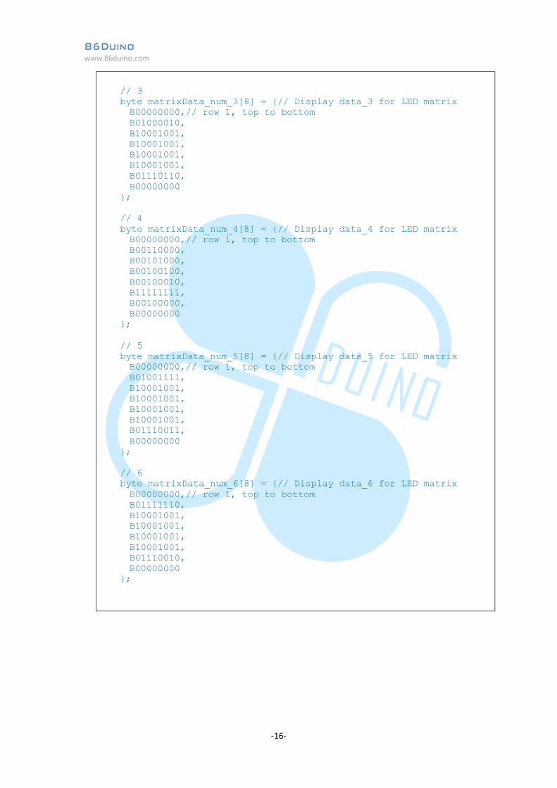
// 3 byte matrixData_num_3[8] = {// Display data_3 for LED matrix B00000000,// row 1, top to bottom B01000010, B10001001, B10001001, B10001001, B10001001, B01110110, B00000000 }; // 4 byte matrixData_num_4[8] = {// Display data_4 for LED matrix B00000000,// row 1, top to bottom B00110000, B00101000, B00100100, B00100010, B11111111, B00100000, B00000000 }; // 5 byte matrixData_num_5[8] = {// Display data_5 for LED matrix B00000000,// row 1, top to bottom B01001111, B10001001, B10001001, B10001001, B10001001, B01110011, B00000000 }; // 6 byte matrixData_num_6[8] = {// Display data_6 for LED matrix B00000000,// row 1, top to bottom B01111110, B10001001, B10001001, B10001001, B10001001, B01110010, B00000000 };
86Duino www.86duino.com
-17-
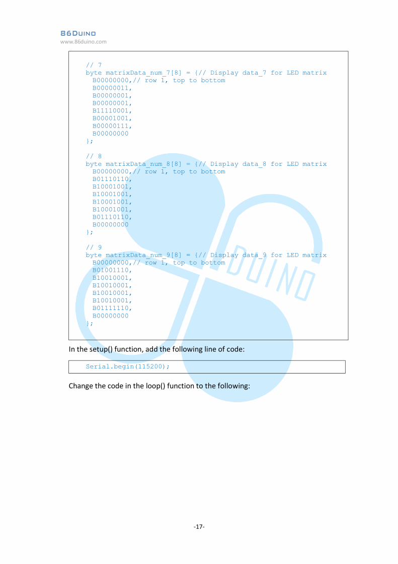
In the setup() function, add the following line of code:
Change the code in the loop() function to the following:
// 7 byte matrixData_num_7[8] = {// Display data_7 for LED matrix B00000000,// row 1, top to bottom B00000011, B00000001, B00000001, B11110001, B00001001, B00000111, B00000000 }; // 8 byte matrixData_num_8[8] = {// Display data_8 for LED matrix B00000000,// row 1, top to bottom B01110110, B10001001, B10001001, B10001001, B10001001, B01110110, B00000000 }; // 9 byte matrixData_num_9[8] = {// Display data_9 for LED matrix B00000000,// row 1, top to bottom B01001110, B10010001, B10010001, B10010001, B10010001, B01111110, B00000000 };
Serial.begin(115200);
86Duino www.86duino.com
-18-
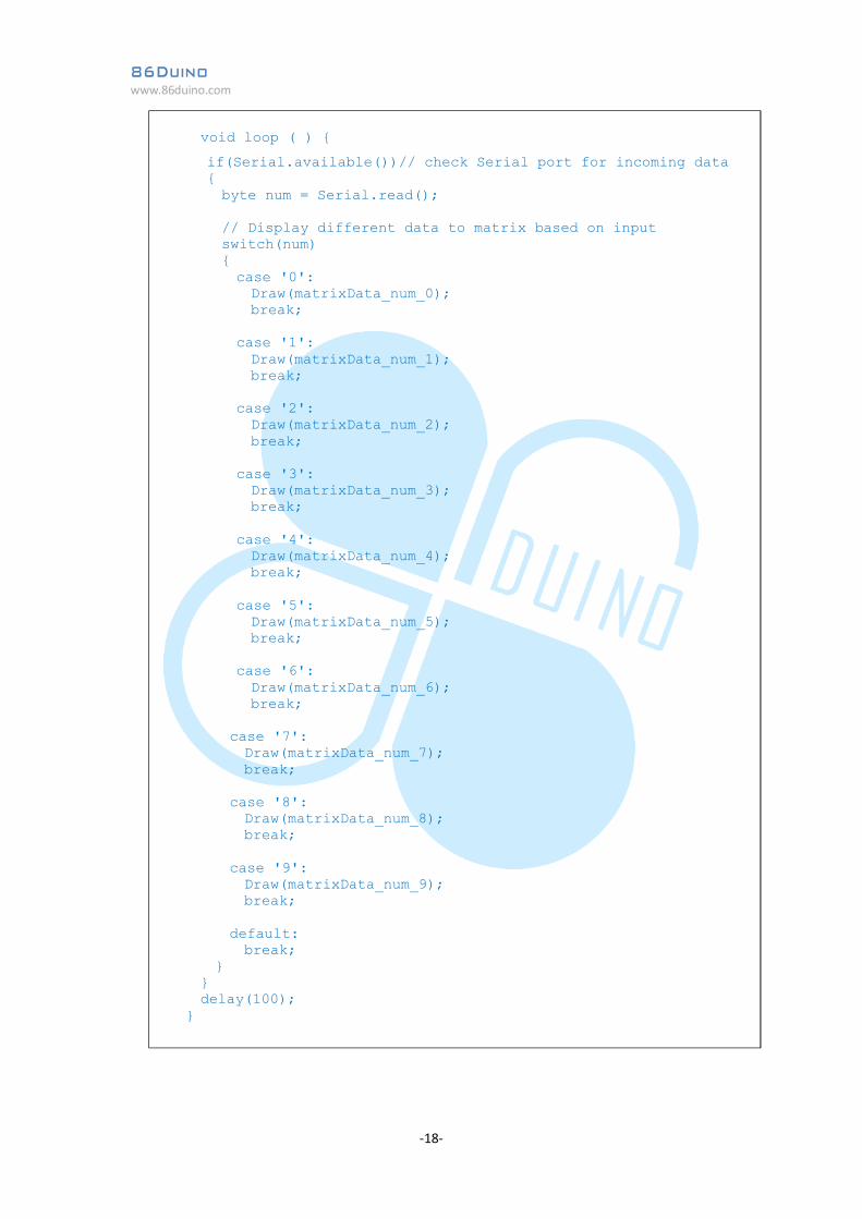
void loop ( ) {
if(Serial.available())// check Serial port for incoming data { byte num = Serial.read(); // Display different data to matrix based on input switch(num) { case '0': Draw(matrixData_num_0); break; case '1': Draw(matrixData_num_1); break; case '2': Draw(matrixData_num_2); break; case '3': Draw(matrixData_num_3); break; case '4': Draw(matrixData_num_4); break; case '5': Draw(matrixData_num_5); break; case '6': Draw(matrixData_num_6); break; case '7': Draw(matrixData_num_7); break; case '8': Draw(matrixData_num_8); break; case '9': Draw(matrixData_num_9); break; default: break; } } delay(100); }
86Duino www.86duino.com
-19-
After the code is compiled and uploaded to the device, launch Serial Monitor
(make sure the baudrate setting match the setting in the sketch). From the Serial
Monitor, enter a value between 0 ~ 9, the LED matrix attached to the EduCake will
display graphic data corresponding to the entered value.
For this exercise, a series of display data are assigned to multiple byte array,
matrixData_num_0 to matrixData_num_9. When the code is compiled and
uploaded to the device, it uses the Serial Monitor to capture input. When an input
is detected (a single numeric value ranging from 0 to 9), the corresponding code
within the switch-case statement is executed to display the associated graphic to the
LED matrix, via the MAX7219 controller.
You can create a variant from the provided sample code, by changing the display
data and associated input variable from the Serial Monitor.
86Duino www.86duino.com
-20-
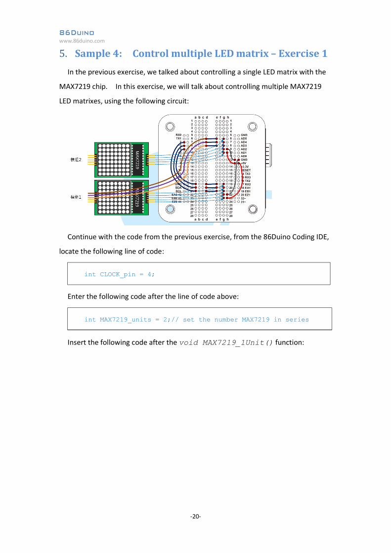
5. Sample 4: Control multiple LED matrix – Exercise 1 In the previous exercise, we talked about controlling a single LED matrix with the
MAX7219 chip. In this exercise, we will talk about controlling multiple MAX7219
LED matrixes, using the following circuit:
Continue with the code from the previous exercise, from the 86Duino Coding IDE,
locate the following line of code:
Enter the following code after the line of code above:
Insert the following code after the void MAX7219_1Unit() function:
int CLOCK_pin = 4;
int MAX7219_units = 2;// set the number MAX7219 in series
86Duino www.86duino.com
-21-
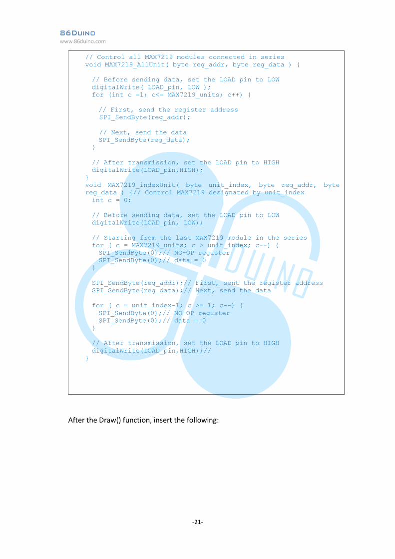
After the Draw() function, insert the following:
// Control all MAX7219 modules connected in series void MAX7219_AllUnit( byte reg_addr, byte reg_data ) { // Before sending data, set the LOAD pin to LOW digitalWrite( LOAD_pin, LOW ); for (int c =1; c<= MAX7219_units; c++) { // First, send the register address
SPI_SendByte(reg_addr); // Next, send the data
SPI_SendByte(reg_data); } // After transmission, set the LOAD pin to HIGH digitalWrite(LOAD_pin,HIGH); } void MAX7219_indexUnit( byte unit_index, byte reg_addr, byte reg_data ) {// Control MAX7219 designated by unit_index int c = 0; // Before sending data, set the LOAD pin to LOW digitalWrite(LOAD_pin, LOW); // Starting from the last MAX7219 module in the series for ( c = MAX7219_units; c > unit_index; c--) { SPI_SendByte(0);// NO-OP register SPI_SendByte(0);// data = 0 } SPI_SendByte(reg_addr);// First, sent the register address SPI_SendByte(reg_data);// Next, send the data for ( c = unit_index-1; c >= 1; c--) { SPI_SendByte(0);// NO-OP register SPI_SendByte(0);// data = 0 } // After transmission, set the LOAD pin to HIGH digitalWrite(LOAD_pin,HIGH);// }
86Duino www.86duino.com
-22-
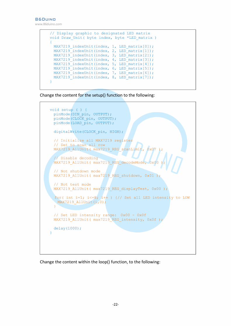
Change the content for the setup() function to the following:
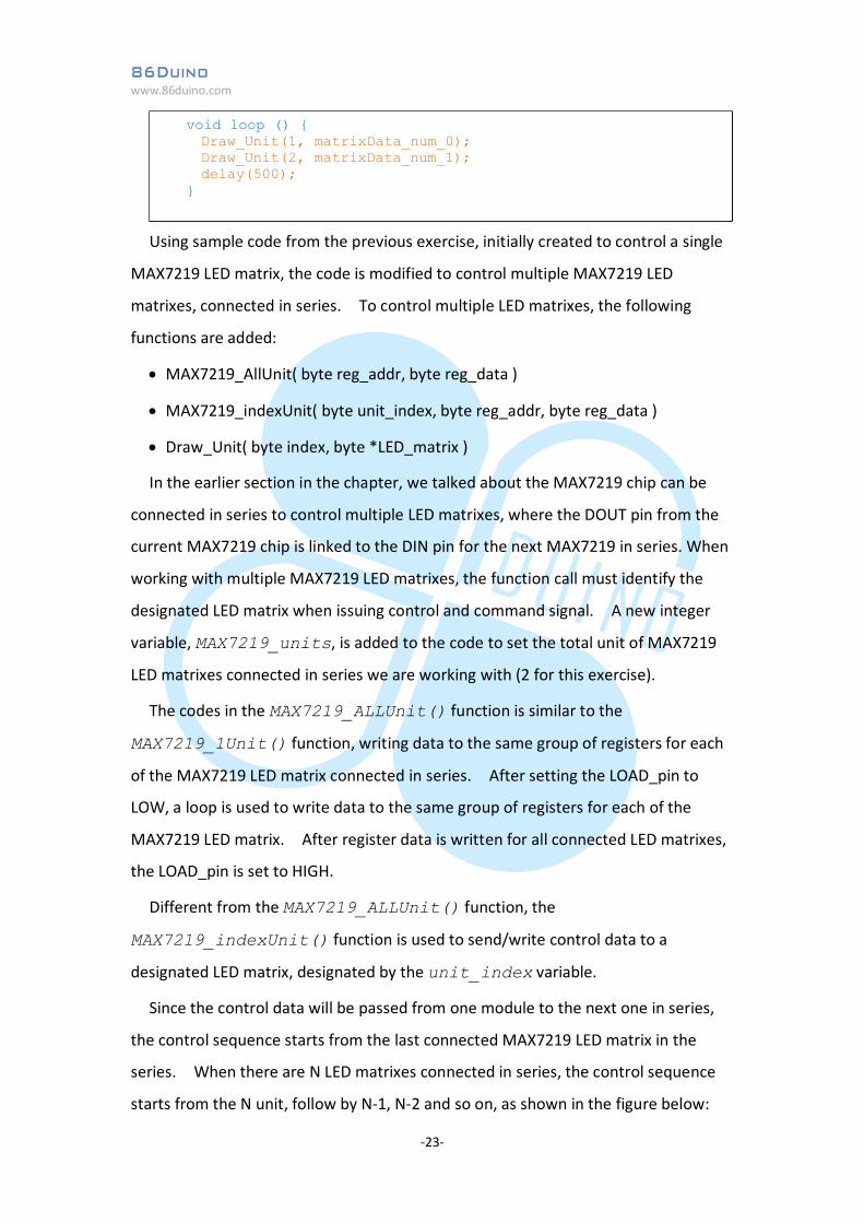
Change the content within the loop() function, to the following:
// Display graphic to designated LED matrix void Draw_Unit( byte index, byte *LED_matrix ) { MAX7219_indexUnit(index, 1, LED_matrix[0]); MAX7219_indexUnit(index, 2, LED_matrix[1]); MAX7219_indexUnit(index, 3, LED_matrix[2]); MAX7219_indexUnit(index, 4, LED_matrix[3]); MAX7219_indexUnit(index, 5, LED_matrix[4]); MAX7219_indexUnit(index, 6, LED_matrix[5]); MAX7219_indexUnit(index, 7, LED_matrix[6]); MAX7219_indexUnit(index, 8, LED_matrix[7]); }
void setup ( ) { pinMode(DIN_pin, OUTPUT); pinMode(CLOCK_pin, OUTPUT); pinMode(LOAD_pin, OUTPUT); digitalWrite(CLOCK_pin, HIGH); // Initialize all MAX7219 register // Set to scan all row MAX7219_AllUnit( max7219_REG_scanLimit, 0x07 ); // Disable decoding MAX7219_AllUnit( max7219_REG_decodeMode, 0x00 ); // Not shutdown mode MAX7219_AllUnit( max7219_REG_shutdown, 0x01 ); // Not test mode MAX7219_AllUnit( max7219_REG_displayTest, 0x00 ); for( int i=1; i<=8; i++ ) {// Set all LED intensity to LOW MAX7219_AllUnit(i,0); } // Set LED intensity range: 0x00 ~ 0x0f MAX7219_AllUnit( max7219_REG_intensity, 0x0f ); delay(1000); }
86Duino www.86duino.com
-23-
Using sample code from the previous exercise, initially created to control a single
MAX7219 LED matrix, the code is modified to control multiple MAX7219 LED
matrixes, connected in series. To control multiple LED matrixes, the following
functions are added:
MAX7219_AllUnit( byte reg_addr, byte reg_data )
MAX7219_indexUnit( byte unit_index, byte reg_addr, byte reg_data )
Draw_Unit( byte index, byte *LED_matrix )
In the earlier section in the chapter, we talked about the MAX7219 chip can be
connected in series to control multiple LED matrixes, where the DOUT pin from the
current MAX7219 chip is linked to the DIN pin for the next MAX7219 in series. When
working with multiple MAX7219 LED matrixes, the function call must identify the
designated LED matrix when issuing control and command signal. A new integer
variable, MAX7219_units, is added to the code to set the total unit of MAX7219
LED matrixes connected in series we are working with (2 for this exercise).
The codes in the MAX7219_ALLUnit() function is similar to the
MAX7219_1Unit() function, writing data to the same group of registers for each
of the MAX7219 LED matrix connected in series. After setting the LOAD_pin to
LOW, a loop is used to write data to the same group of registers for each of the
MAX7219 LED matrix. After register data is written for all connected LED matrixes,
the LOAD_pin is set to HIGH.
Different from the MAX7219_ALLUnit() function, the
MAX7219_indexUnit() function is used to send/write control data to a
designated LED matrix, designated by the unit_index variable.
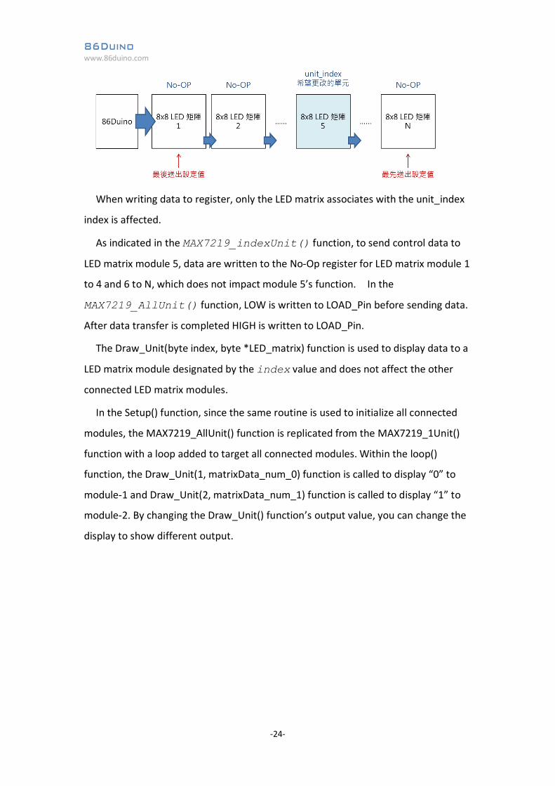
Since the control data will be passed from one module to the next one in series,
the control sequence starts from the last connected MAX7219 LED matrix in the
series. When there are N LED matrixes connected in series, the control sequence
starts from the N unit, follow by N-1, N-2 and so on, as shown in the figure below:
void loop () { Draw_Unit(1, matrixData_num_0); Draw_Unit(2, matrixData_num_1); delay(500); }
86Duino www.86duino.com
-24-
When writing data to register, only the LED matrix associates with the unit_index
index is affected.
As indicated in the MAX7219_indexUnit() function, to send control data to
LED matrix module 5, data are written to the No-Op register for LED matrix module 1
to 4 and 6 to N, which does not impact module 5’s function. In the
MAX7219_AllUnit() function, LOW is written to LOAD_Pin before sending data.
After data transfer is completed HIGH is written to LOAD_Pin.
The Draw_Unit(byte index, byte *LED_matrix) function is used to display data to a
LED matrix module designated by the index value and does not affect the other
connected LED matrix modules.
In the Setup() function, since the same routine is used to initialize all connected
modules, the MAX7219_AllUnit() function is replicated from the MAX7219_1Unit()
function with a loop added to target all connected modules. Within the loop()
function, the Draw_Unit(1, matrixData_num_0) function is called to display “0” to
module-1 and Draw_Unit(2, matrixData_num_1) function is called to display “1” to
module-2. By changing the Draw_Unit() function’s output value, you can change the
display to show different output.
86Duino www.86duino.com
-25-
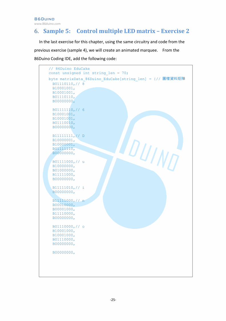
6. Sample 5: Control multiple LED matrix – Exercise 2 In the last exercise for this chapter, using the same circuitry and code from the
previous exercise (sample 4), we will create an animated marquee. From the
86Duino Coding IDE, add the following code:
// 86Duino EduCake const unsigned int string_len = 70;
byte matrixData_86Duino_EduCake[string_len] = {// 圖樣資料矩陣 B01110110,// 8 B10001001, B10001001, B01110110, B00000000, B01111110,// 6 B10001001, B10001001, B01110010, B00000000, B11111111,// D B10000001, B10000001, B01111110, B00000000, B01111000,// u B10000000, B01000000, B11111000, B00000000, B11111010,// i B00000000, B11111000,// n B00010000, B00001000, B11110000, B00000000, B01110000,// o B10001000, B10001000, B01110000, B00000000, B00000000,
86Duino www.86duino.com
-26-
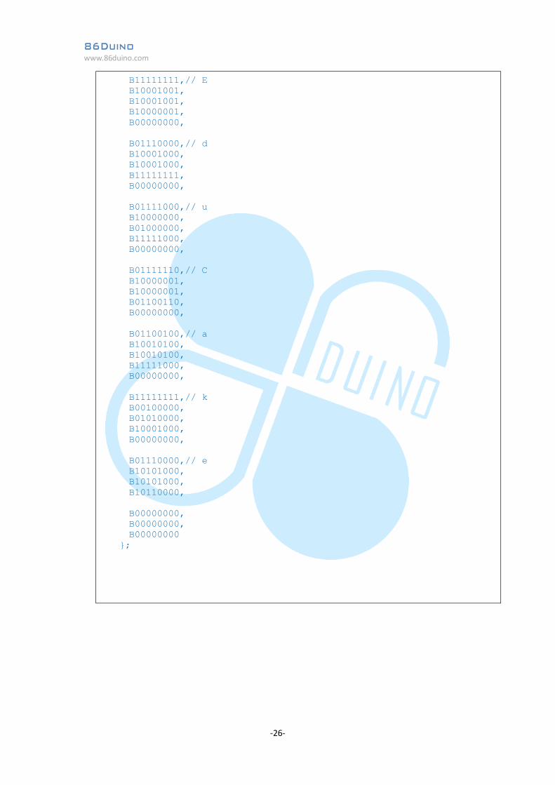
B11111111,// E B10001001, B10001001, B10000001, B00000000, B01110000,// d B10001000, B10001000, B11111111, B00000000, B01111000,// u B10000000, B01000000, B11111000, B00000000, B01111110,// C B10000001, B10000001, B01100110, B00000000, B01100100,// a B10010100, B10010100, B11111000, B00000000, B11111111,// k B00100000, B01010000, B10001000, B00000000, B01110000,// e B10101000, B10101000, B10110000, B00000000, B00000000, B00000000 };
86Duino www.86duino.com
-27-
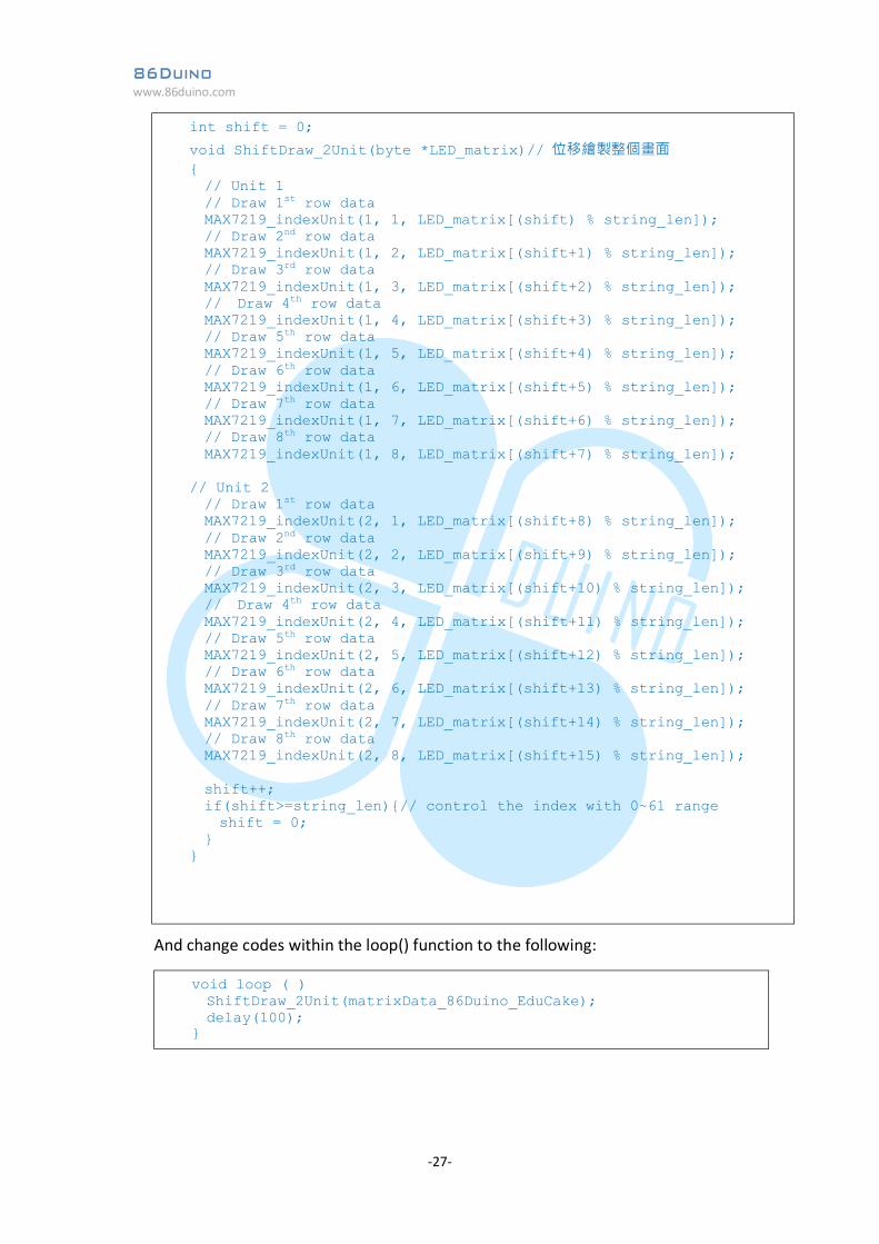
And change codes within the loop() function to the following:
int shift = 0;
void ShiftDraw_2Unit(byte *LED_matrix)// 位移繪製整個畫面 { // Unit 1 // Draw 1st row data MAX7219_indexUnit(1, 1, LED_matrix[(shift) % string_len]); // Draw 2nd row data MAX7219_indexUnit(1, 2, LED_matrix[(shift+1) % string_len]); // Draw 3rd row data MAX7219_indexUnit(1, 3, LED_matrix[(shift+2) % string_len]); // Draw 4th row data MAX7219_indexUnit(1, 4, LED_matrix[(shift+3) % string_len]); // Draw 5th row data MAX7219_indexUnit(1, 5, LED_matrix[(shift+4) % string_len]); // Draw 6th row data MAX7219_indexUnit(1, 6, LED_matrix[(shift+5) % string_len]); // Draw 7th row data MAX7219_indexUnit(1, 7, LED_matrix[(shift+6) % string_len]); // Draw 8th row data MAX7219_indexUnit(1, 8, LED_matrix[(shift+7) % string_len]); // Unit 2 // Draw 1st row data MAX7219_indexUnit(2, 1, LED_matrix[(shift+8) % string_len]); // Draw 2nd row data MAX7219_indexUnit(2, 2, LED_matrix[(shift+9) % string_len]); // Draw 3rd row data MAX7219_indexUnit(2, 3, LED_matrix[(shift+10) % string_len]); // Draw 4th row data MAX7219_indexUnit(2, 4, LED_matrix[(shift+11) % string_len]); // Draw 5th row data MAX7219_indexUnit(2, 5, LED_matrix[(shift+12) % string_len]); // Draw 6th row data MAX7219_indexUnit(2, 6, LED_matrix[(shift+13) % string_len]); // Draw 7th row data MAX7219_indexUnit(2, 7, LED_matrix[(shift+14) % string_len]); // Draw 8th row data MAX7219_indexUnit(2, 8, LED_matrix[(shift+15) % string_len]); shift++; if(shift>=string_len){// control the index with 0~61 range shift = 0; } }
void loop ( ) ShiftDraw_2Unit(matrixData_86Duino_EduCake); delay(100); }
86Duino www.86duino.com
-28-
With the above code added, you can see the string of character, “86Duino
EduCake”, continuously scroll through the display, like an animated marquee. The
Shift_2Unit() function has similar fuction as the ShiftDraw() function with additional
display data added. In this exercise, the total length of the displayed graphic
involve 70 columns of data, and uses control index within the 0 ~ 69 range. The
const unsigned int string_len variable is used to specify the length of the column in
the LED matrix.