Edgewise compressive strength of corrugated fiberboard ... · PDF fileEdgewise compressive...
25
WI 060308.04 T 811 DRAFT NO. 3 DATE March 12, 2007 TAPPI WORKING GROUP CHAIRMAN Ben Frank SUBJECT CATEGORY FISCOTEC RELATED METHODS See “Additional Information” Approved by the Standard Specific Interest Group for this Test Method TAPPI CAUTION: This Test Method may include safety precautions which are believed to be appropriate at the time of publication of the method. The intent of these is to alert the user of the method to safety issues related to such use. The user is responsible for determining that the safety precautions are complete and are appropriate to their use of the method, and for ensuring that suitable safety practices have not changed since publication of the method. This method may require the use, disposal, or both, of chemicals which may present serious health hazards to humans. Procedures for the handling of such substances are set forth on Material Safety Data Sheets which must be developed by all manufacturers and importers of potentially hazardous chemicals and maintained by all distributors of potentially hazardous chemicals. Prior to the use of this method, the user must determine whether any of the chemicals to be used or disposed of are potentially hazardous and, if so, must follow strictly the procedures specified by both the manufacturer, as well as local, state, and federal authorities for safe use and disposal of these chemicals. Edgewise compressive strength of corrugated fiberboard (short column test) (Revision of T 811 om-02) (underscores and strikeouts indicate changes from Draft 2) 1. Scope 1.1 This method describes procedures for determining the edgewise compressive strength (ECT), perpendicular to the axis of the flutes, of a short column of single-, double-, or triple-wall corrugated fiberboard (1). 1.2 The method includes procedures for cutting the test specimen, specimen support (waxed edges), and two procedures for applying the compressive force (constant strain rate, or constant load rate). Studies have shown that any combination of these procedures will yield the same test results with the stated precision (Section 9).
-
Upload
nguyenmien -
Category
Documents
-
view
245 -
download
0
Transcript of Edgewise compressive strength of corrugated fiberboard ... · PDF fileEdgewise compressive...

WI 060308.04
T 811
DRAFT NO. 3
DATE March 12, 2007 TAPPI
WORKING GROUP CHAIRMAN Ben Frank
SUBJECT CATEGORY FISCOTEC
RELATED METHODS See “Additional Information”
Approved by the Standard Specific Interest Group for this Test Method
TAPPI
CAUTION: This Test Method may include safety precautions which are believed to be appropriate at the time of publication of the method. The intent of these is to alert the user of the method to safety issues related to such use. The user is responsible for determining that the safety precautions are complete and are appropriate to their use of the method, and for ensuring that suitable safety practices have not changed since publication of the method. This method may require the use, disposal, or both, of chemicals which may present serious health hazards to humans. Procedures for the handling of such substances are set forth on Material Safety Data Sheets which must be developed by all manufacturers and importers of potentially hazardous chemicals and maintained by all distributors of potentially hazardous chemicals. Prior to the use of this method, the user must determine whether any of the chemicals to be used or disposed of are potentially hazardous and, if so, must follow strictly the procedures specified by both the manufacturer, as well as local, state, and federal authorities for safe use and disposal of these chemicals.
Edgewise compressive strength of corrugated fiberboard (short column test)
(Revision of T 811 om-02) (underscores and strikeouts indicate changes from Draft 2)
1. Scope
1.1 This method describes procedures for determining the edgewise compressive strength (ECT),
perpendicular to the axis of the flutes, of a short column of single-, double-, or triple-wall corrugated fiberboard (1).
1.2 The method includes procedures for cutting the test specimen, specimen support (waxed edges), and two
procedures for applying the compressive force (constant strain rate, or constant load rate). Studies have shown that any
combination of these procedures will yield the same test results with the stated precision (Section 9).

T 811 om-02 Edgewise compressive strength of corrugated / 2 fiberboard (short column test)
2. Significance
2.1 Research has shown that the edgewise compressive strength of specimens with flutes vertical, in
combination with the flexural stiffness of the combined board and box dimensions, relates to the top-to-bottom
compressive strength of vertically fluted corrugated fiberboard shipping containers (2,3).
2.2 This method may also be used for comparing the edgewise compressive strength of different lots of
similar combined boards or for comparing different material combinations (4,5).
3. Apparatus
3.1 Compression testing machine1 meeting the requirements of either 3.1.1 or 3.1.2, and 3.1.3, 3.1.4, and
3.1.5.
3.1.1 Rigid Support Compression Tester. Two platens, one rigidly supported and the other driven. Each platen
shall have a working area of approximately 100 cm2 (16 in.2). The platens are not to have not more than 0.050 mm
(0.002 in.) lateral relative movement, and the rigidly supported platen not more than 0.150 mm (0.006 in.) movement,
perpendicular to the surface, within a load range of 0 to 2224 N (0-500 lbf). Within the specimen contact area, each
platen shall be flat within 0.0025 mm (0.0001 in.) of the mean platen surface, and the platens shall remain parallel to each
other within 1 part in 2000 throughout the test (6).
3.1.1.1 Within a range of platen separations necessary to cause compressive failure of the test specimen, and
within a load range of 0 to 2224 N (0-500 lbf), the speed of the driven platen shall be controllable at 12.5 ± 0.25 mm (0.5
± 0.01 in.) per minute. (For convenience, the test machine should be capable of rapid return and automatic, settable
positioning).
3.1.2 Flexible Beam Compression Tester. Two platens, one flexible beam supported and the other driven. Each
platen shall have a working area of approximately 100 cm2 (16 in.2). Within the specimen contact area, each platen shall
be flat within 0.0025 mm (0.0001 in.) of the mean platen surface, and the platens shall remain parallel to each other
within 1 part in 2000 throughout the test. The platens are required to have not more than 0.050 mm (0.002 in.) lateral
relative movement.
3.1.2.1 Within a range of platen separations necessary to cause compressive failure of the test specimen, and
within a load range of 0 to 2224 N (0-500 lbf), the speed of the driven platen shall be controlled so that the rate of force
increase (without considering specimen deformation) is 111 ± 22 N/s (25 ± 5 lbf/s) (6).
3.1.3 The driven platen shall be moveable to achieve an initial platen separation of at least 60 mm (2.36 in.).
3.1.4 The tester shall have a capacity of at least 2224 N (500 lbf).
1
Names of suppliers of testing equipment and materials for this method may be found on the Test Equipment Suppliers list in the set of TAPPI Test Methods, or may be available from the TAPPI Quality and Standards Department.
3 / Edgewise compressive strength of corrugated T 811 om-02 fiberboard (short column test)
3.1.5 The tester shall have a means for measuring and indicating the maximum load sustained by the test
specimen with an accuracy of 0.5% or better between a measured load of 440 N (100 lb) and the equipment’s maximum
load. Below this measured load, the accuracy shall be 2.2 N (0.5 lbf), or better whichever is greater.
3.2 A means such as a saw or other device for cutting specimens having clean, parallel and perpendicular
edges, within the tolerances specified in 6.2 and 6.3. Opposite edges shall be parallel to each other and perpendicular to
adjacent edges (7, 8).
3.2.1 Knife cutter, single knife device with guides or, preferably, a twin-knife motorized or pneumatically
driven device to cut the test specimens according to the specifications in Section 6. The knives must be sharp and of the
single-bevel type and arranged in the device so that the unbevelled side is toward the test piece and at 90° to the
specimen's surface.
3.2.2 Saw, circular, equipped with a sharp, no-set (hollow ground or taper ground is desirable) saw blade. The
saw blade shall be 90° to the table supporting the specimen.
3.3 A means for supporting the specimen at the initiation of the test so that the applied force is exactly
parallel to the flutes.
3.3.1 Metal guide blocks (Fig. 1) to be used with the waxed edge specimens (7.5). Two are required to align
the specimen vertically in the testing machine.
4. Sampling
Samples shall be obtained in accordance with TAPPI T 400 “Sampling and Accepting a Single Lot of Paper,
Paperboard, Containerboard, or Related Product.”
5. Conditioning
Precondition and condition the sample in accordance with TAPPI T 402 “Standard Conditioning and Testing
Atmospheres for Paper, Board, Pulp Handsheets, and Related Products.” Waxed edge specimens shall be conditioned an
additional minimum of 2 hours after waxing and before testing (8 9)
6. Test specimens
6.1 From each test unit accurately cut at least 10 specimens with the motorized knife or circular saw or
other method that will cut clean, parallel, and perpendicular edges.
6.1.1 If the test specimens are to be taken from corrugated shipping containers, they should be taken
from areas away from scorelines, joints, and closures. Specimens should be representative of the materials being
tested. For example, if roughly 25% of a box is printed, roughly 25% of the samples should be collected from the
printed areas. Specimens should not be taken from obviously damaged areas and/or areas not representative of the
container as a whole.
6.2 The loading (width) edges shall be parallel to each other and perpendicular to the axis of the flutes

T 811 om-02 Edgewise compressive strength of corrugated / 4 fiberboard (short column test)
(Fig. 2). Cut the specimens to a width of 50.8 ± 0.8 mm (2.00 ± 0.03 in.).
6.3 Specimens to be tested using this procedure shall be cut to a height of 31.8 ± 1.6 mm (1.25 ± 0.06
in.) for B-flute, 38.1 ± 1.6 mm (1.50 ± 0.06 in.) for C-flute, and 50.8 ± 1.6mm (2.00 ± 0.06 in.) for A-flute and
typical for all double- and triple-wall board (1,6). These heights meet the Euler criteria for pure compression failure
in a short column for their respective structures (8). For some thin double-wall board (e.g., EB double-wall), and for
other flute structures (e.g., E flute), different heights may be required to achieve a pure compression failure in the
test specimens.
NOTE 1: In some U.S. Federal and Military Specifications and Standards for corrugated board, the short column crush test is required. The
procedure is technically identical to that described here in Sections 4-6 except for specimen size. The height for all flute
constructions, single-, double-, and triple-wall, is 31.8 ± 1.6 mm (1.25 ± 0.06 in.). When testing against these
specifications, this height is to be used.
NOTE 2: In some testing protocols (e.g., compliance with National Motor Freight Classification item 222), alternate numbers of specimens may
be required for testing. The test procedure is technically identical to that described here in Sections 4-6.
NOTE 3: Other procedures are sometimes used which require different specimen dimensions, specimen geometry (10), or specimen support
techniques. These may include, but are not limited to: TAPPI T 839 “Edgewise Compressive Strength of Corrugated
Fiberboard using the Clamp Method (Short Column Test)” (11), TAPPI T 841 “Edgewise Compressive Strength of
Corrugated Fiberboard using the Morris Method (Short Column Test)”, TAPPI T 838 “Edge Crush Test Using Neckdown”
(12), and FEFCO test Method No. 8 “Edgewise Crush Resistance of Corrugated Fiberboard.” The FEFCO method requires
testing specimens cut to 100 mm (3.94 in.) wide and 25 mm (0.98 in.) high without any additional specimen support such
as waxed edges, or mechanical support beyond the initial vertical alignment.
The procedures described in Notes 1, 2, and 3 will not, necessarily, yield the same results as the official test method. (13,
14)
6.4 Prepare test specimens with waxed edge reinforcement as follows: Dip each loading edge in molten
paraffin at 69-74°C (156-165°F) approximate melting point, 52°C (125°F), to a depth of 6 mm (1/4 in.) and hold there
until the absorbed paraffin, as determined visually, begins to migrate above the 6 mm (1/4 in.) dipped zone. Normally, a
3 second dip in molten paraffin is satisfactory. If excessively rapid migration is encountered, reduce the temperature of
the molten paraffin. Immediately after dipping, momentarily blot the loading edges of the specimen on paper toweling
preheated on a hot plate maintained at 77-82°C (171°-180°F).
NOTE 4: The following alternative procedure for impregnating the loading edges of specimens with paraffin wax is permissible. Place the
edge on a paraffin wax saturated pad, such as paper toweling, heated on a hot plate maintained at 77-82°C (171-180°F) until the
paraffin wax impregnates the specimen to the desired 6 mm (1/4 in.) depth. Generally, this method is slower than the dipping
method and therefore permits better control of the depth of paraffin wax penetration for specimens in which paraffin wax migration
is rapid.
5 / Edgewise compressive strength of corrugated T 811 om-02 fiberboard (short column test)
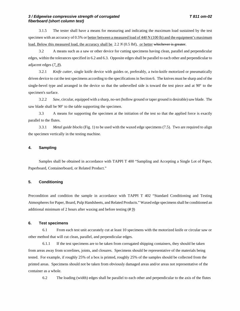
NOTE 5: When reinforcing the loading edges of waxed or curtain coated boards, care must be taken so that the heat of the reinforcing
paraffin wax does not adversely affect the integrity of the board’s structure in the area of the edge wax impregnation. Evidence of
proper treatment will be that in performing the test, failure occurs away from the reinforced area.
7. Procedure
7.1 Perform all tests in the conditioning atmosphere.
7.2 The rate of platen movement required for a flexible beam compression machine has been determined to
be 111 ± 22 N/s (25 ± 5 lbf/s). Record the platen movement rate actually used. On most machines this rate of platen
movement will be 13-51 mm (0.5-2.0 in.) per minute depending on the load range at the beam.
7.3 The rate of platen movement for each rigid support compression machine should be set to 12.5 ± 0.25 mm
(0.5 ± 0.01 in.) per minute.
7.4 Measure the width (nominally 50.8-mm (2-in.)) dimension of each specimen to the nearest 1 mm (1/32
in.).
7.5 Center the specimen on the platen. Place a guide block on each side of the specimen centrally located
relative to it so that the flutes are held perpendicular to the platen. Place the blocks' largest face up, with the offset ends
adjacent and in contact with the specimen above the paraffin areas.
7.5.1 Apply a compressive force to the specimen. Verify the platen movement rate described in 7.2 or 7.3.
When the force on the specimen is between 22 and 67 N (5 and 15 lbf), remove both guide blocks and, without altering
the platen movement rate, continue to apply force until the specimen fails. A valid test is when one or both liners have
buckled in the unwaxed center portion of the specimen. If neither liner shows a buckling failure in the unwaxed area of
the specimen, or if failure occurs in the waxed portion of the sample, the test may be declared invalid.
7.6 Record the maximum load in newtons (pounds-force), the specimen width, and whether or not the
specimen exhibited a valid failure.
8. Report
8.1 For each test unit, report:
8.1.1 Average maximum load per unit width for valid tests calculated from average maximum load and
specimen width in kilonewtons per meter (pounds-force per in.).
8.1.2 Standard deviation among valid determinations in kilonewtons per meter (pounds-force per in.).
8.1.3 Number of valid test determinations.
8.1.4 A description of material tested.
8.1.5 A statement that the test was conducted in compliance with this test method and a description of any
deviations.

T 811 om-02 Edgewise compressive strength of corrugated / 6 fiberboard (short column test)
9. Precision
9.1 Repeatability (within a laboratory) = 4%.
9.2 Reproducibility (between laboratories) = 19%.
Repeatability and reproducibility are estimates of the maximum difference (at 95% confidence) that should be expected
when comparing test results for materials similar to those described below under similar test conditions. These estimates
may not be valid for different materials and testing conditions.
9.3 The estimates of repeatability and reproducibility listed above are based on data from the CTS
Containerboard Interlaboratory Program using testing conducted in 2005 and 2006. The data included 17 rounds of
testing on 5 different samples of “C” flute corrugated board in either 42-26-42 or 35-26-35 board combinations. The
precision estimates are based on 10 determinations per test result and 1 test result per lab for each of the 17 rounds of
testing. Only laboratories that reported using rigid-platen type instruments and TAPPI standard conditioning
atmospheres are included in the calculations.
9.4 Additional Information. The precision statement above (9.1 through 9.3) replaced information derived
from a study conducted in October 1966 in cooperation with the ASTM Committee D-6, Sub IV, October 1966, among
nine laboratories on five different corrugated combinations. The estimates of repeatability (6%) and reproducibility
(23%) are not significantly changed in this revision. However it should be noted that the 1966 results would have been
derived from analog, deflecting-beam type instruments.
10. Keywords
Corrugated boards, Edge crush tests, Compression strength.
11. Additional information
11.1 Effective date of issue: to be assigned.
11.2 This method is referenced in the alternate requirements of National Railroad Freight Committee, Uniform
Freight Classification, and the National Motor Freight Traffic Association Inc.,/American Trucking Association, National
Motor Freight Classification. The carrier classification rules (Alternate Rule 41, Item 222) define the minimum ECT
requirements for corrugated boxes used in the common carrier surface transportation system.
11.3 Related methods: ISO 13821 “Corrugated Fiberboard – Determination of Edgewise Crush Resistance –
Waxed Edge Method.” See also Note 3.
12. Literature cited
1. Koning, J. W., Jr., “Comparison of Two Specimen Shapes for Short Column Test of Corrugated Fiberboard,” U.S.
Forest Service Research Note FPL-0109 (October 1965).
2. McKee, R. C., Gander, J. W., and Wachuta, J. R., “Edgewise Compression Strength of Corrugated Board,”
Paperboard Packaging 46 (11); 70 (1961).

7 / Edgewise compressive strength of corrugated T 811 om-02 fiberboard (short column test)
3. McKee, R. C., Gander, J. W. and Wachuta, J. R., “Compression Strength Formula for Corrugated Boxes,”
Paperboard Packaging 48 (8): 149 (1963).
4. Maltenfort, G. G., “Compression Strength of Corrugated,” Paperboard Packaging 48 (8): 160 (1963).
5. Moody, R. C., “Edgewise Compressive Strength of Corrugated Fiberboard as Determined by Local Instability,”
U.S. Forest Service Research paper FPL 46 (December 1965).
6. Moody, R. C., and Koning, J. W., Jr., “Effect of Loading Rate on the Edgewise Compressive Strength of
Corrugated Fiberboard,” U.S. Forest Service Research Note FPL-0121 (April 1966).
7. McClain, T. E. And Boltnott, “Crush Tests Rely on Parallel-to-flute Loading,” Tappi Journal 65(3): 148(1982).
8. Eriksson, L., Boxboard Containers, March 1979
9. Urbanik, T. J., Catlin, A. H., Friedman, D. R., Lund, R. C., “Edgewise Crush Test Streamlined by Shorter Time
After Waxing,” Tappi Journal 77 (1): 83 (1994).
10. Koning, J. W., Jr., “A Short Column Crush Test of Corrugated Fiberboard,” Tappi 47 (3): 134 (1964).
11. Schrampfer, K. E., and Whitsitt, W. J., “Clamped Specimen Testing: A Faster Edgewise Crush Procedure,” Tappi
71 (10): 65 (1988).
12. Koning, J. W., “Towards an International Standard for the Edgewise Compression Test of Corrugated Board,”
Tappi Journal 71 (10): 62 (1988).
13. Schrampfer, K.E., Whitsitt, W.J., and Baum, G.A., The Institute of Paper Science and Technology, Project 2695-
24, Report One (February 27, 1987).
14. Frank, B., Corrugating International, August 2003
Fig. 1. Metal guide block.

T 811 om-02 Edgewise compressive strength of corrugated / 8 fiberboard (short column test)
Fig. 2. Edgewise test specimen for B-flute.
Your comments and suggestions on this procedure are earnestly requested and should be sent to the TAPPI
Standards Department. g

August 15, 2006 TO: SSIG for T 811 FROM: Benjamin Frank
Working Group Chairman RE: Ballot on Draft 2 of T 811 All suggested revisions on affirmative votes from Draft 1 have been incorporated into this draft. The only comment not resolved was a negative vote which suggested changes in Section 3 regarding parallelism of the platens, machine speed, etc. Contact with the negative voter indicated that he has no data to support these suggested changes. I am requesting that the SSIG vote this negative as nonpersuasive. Per the test method guidelines, this vote on Draft 2 is ONLY to approve overriding this negative vote. Although any additional comments may be addressed if deemed technically sound, the only comments or votes on this draft that will be required to be considered are those regarding the negative vote from Draft 1. Your affirmative vote will indicate that you agree that the negative should be found nonpersuasive. Thank you for your response by the deadline.

WI 060308.04
T 811
DRAFT NO. 2
DATE August 16, 2006 TAPPI
WORKING GROUP CHAIRMAN Ben Frank
SUBJECT CATEGORY FISCOTEC
RELATED METHODS See “Additional Information”
Approved by the Standard Specific Interest Group for this Test Method
TAPPI
CAUTION: This Test Method may include safety precautions which are believed to be appropriate at the time of publication of the method. The intent of these is to alert the user of the method to safety issues related to such use. The user is responsible for determining that the safety precautions are complete and are appropriate to their use of the method, and for ensuring that suitable safety practices have not changed since publication of the method. This method may require the use, disposal, or both, of chemicals which may present serious health hazards to humans. Procedures for the handling of such substances are set forth on Material Safety Data Sheets which must be developed by all manufacturers and importers of potentially hazardous chemicals and maintained by all distributors of potentially hazardous chemicals. Prior to the use of this method, the user must determine whether any of the chemicals to be used or disposed of are potentially hazardous and, if so, must follow strictly the procedures specified by both the manufacturer, as well as local, state, and federal authorities for safe use and disposal of these chemicals.
Edgewise compressive strength of corrugated fiberboard (short column test)
(Revision of T 811 om-02)
1. Scope
1.1 This method describes procedures for determining the edgewise compressive strength (ECT),
perpendicular to the axis of parallel to the flutes, of a short column of single-, double-, or triple-wall corrugated
fiberboard (1).
1.2 The method includes procedures for cutting the test specimen, specimen support (waxed edges), and two
procedures for applying the compressive force (constant strain rate, or constant load rate). Studies have shown that any
combination of these procedures will yield the same test results with the stated precision (Section 9).

T 811 om-02 Edgewise compressive strength of corrugated / 2 fiberboard (short column test)
2. Significance
2.1 Research has shown that the edgewise compressive strength of specimens with flutes vertical, in
combination with the flexural stiffness of the combined board and box dimensions, relates to the top-to-bottom
compressive strength of vertically fluted corrugated fiberboard shipping containers (2,3).
2.2 This method may also be used for comparing the edgewise compressive strength of different lots of
similar combined boards or for comparing different material combinations (4,5).
3. Apparatus
3.1 Compression testing machine1 meeting the requirements of either 3.1.1 or 3.1.2, and 3.1.3, 3.1.4, and
3.1.5.
3.1.1 Rigid Support Compression Tester. Two platens, one rigidly supported and the other driven. Each platen
shall have a working area of approximately 100 cm2 (16 in.2). The platens are not to have not more than 0.050 mm
(0.002 in.) lateral relative movement, and the rigidly supported platen not more than 0.150 mm (0.006 in.) movement,
perpendicular to the surface, within a load range of 0 to 2224 N (0-500 lbf). Within the specimen contact area, each
platen shall be flat within 0.0025 mm (0.0001 in.) of the mean platen surface, and the platens shall remain parallel to each
other within 1 part in 2000 throughout the test (6).
3.1.1.1 Within a range of platen separations necessary to cause compressive failure of the test specimen, and
within a load range of 0 to 2224 N (0-500 lbf), the speed of the driven platen shall be controllable at 12.5 ± 0.25 mm (0.5
± 0.01 in.) per minute. (For convenience, the test machine should be capable of rapid return and automatic, settable
positioning).
3.1.2 Flexible Beam Compression Tester. Two platens, one flexible beam supported and the other driven. Each
platen shall have a working area of approximately 100 cm2 (16 in.2). Within the specimen contact area, each platen shall
be flat within 0.0025 mm (0.0001 in.) of the mean platen surface, and the platens shall remain parallel to each other
within 1 part in 2000 throughout the test. The platens are required to have not more than 0.050 mm (0.002 in.) lateral
relative movement.
3.1.2.1 Within a range of platen separations necessary to cause compressive failure of the test specimen, and
within a load range of 0 to 2224 N (0-500 lbf), the speed of the driven platen shall be controlled so that the rate of force
increase (without considering specimen deformation) is 111 ± 22 N/s (25 ± 5 lbf/s) (6).
3.1.3 The driven platen shall be moveable to achieve an initial platen separation of at least 60 mm (2.36 in.).
3.1.4 A The tester shall have a capacity of at least 2224 N (500 lbf).
3.1.5 A The tester shall have a means for measuring and indicating the maximum load sustained by the test
specimen with an accuracy of 0.5% or 2.2 N (0.5 lbf), whichever is greater.
1
Names of suppliers of testing equipment and materials for this method may be found on the Test Equipment Suppliers list in the set of TAPPI Test Methods, or may be available from the TAPPI Quality and Standards Department.

3 / Edgewise compressive strength of corrugated T 811 om-02 fiberboard (short column test)
3.2 3.1.6 A means such as a saw or other device for cutting specimens having clean, parallel and perpendicular
edges, within the tolerances specified in 6.2 and 6.3. Opposite edges shall be parallel to each other and perpendicular to
adjacent edges (7, 8).
3.2.1 3.1.6.1 Knife cutter, single knife device with guides or, preferably, a twin-knife motorized or
pneumatically driven device to cut the test specimens according to the specifications in Section 6. The knives must be
sharp and of the single-bevel type and arranged in the device so that the unbevelled side is toward the test piece and at
90° to the specimen's surface.
3.2.2 3.1.6.2 Saw, circular, equipped with a sharp, no-set (hollow ground or taper ground is desirable) saw
blade. The saw blade shall be 90° to the table supporting the specimen.
3.3 3.1.7 A means for supporting the specimen at the initiation of the test so that the applied force is exactly
parallel to the flutes.
3.3.1 3.1.7.1 Metal guide blocks (Fig. 1) to be used with the waxed edge specimens (7.5). Two are required
to align the specimen vertically in the testing machine.
4. Sampling
Samples shall be obtained in accordance with TAPPI T 400 “Sampling and Accepting a Single Lot of Paper,
Paperboard, Containerboard, or Related Product.”
5. Conditioning
Precondition and condition the sample in accordance with TAPPI T 402 “Standard Conditioning and Testing
Atmospheres for Paper, Board, Pulp Handsheets, and Related Products.” Waxed edge specimens shall be conditioned an
additional minimum of 2 hours after waxing and before testing (8 9)
6. Test specimens
6.1 From each test unit accurately cut at least 10 specimens with the motorized knife or circular saw or other
method that will cut clean, parallel, and perpendicular edges. If the test specimens are to be taken from corrugated
shipping containers, they should be taken from areas away from scorelines, joints, and
closures. Specimens should not be taken from obviously damaged areas and areas not representative of the container as a
whole.
6.2 The loading (width) edges shall be parallel to each other and perpendicular to the axis of the flutes (Fig.
2). Cut the specimens to a width of 50.8 ± 0.8 mm (2.00 ± 0.031 in.).
6.3 Specimens to be tested using this procedure shall be cut to a height of 31.8 ± 1.6 mm (1.25 ± 0.063 in.)
for B-flute, 38.1 ± 1.6 mm (1.50 ± 0.063 in.) for C-flute, and 50.8 ± 1.6 mm (2.00 ± 0.063 in.) for A-flute and for all
double- and triple-wall board (1, 6).
T 811 om-02 Edgewise compressive strength of corrugated / 4 fiberboard (short column test)
NOTE 1: In some U.S. Federal and Military Specifications and Standards for corrugated board, the short column crush test is required. The
procedure is technically identical to that described here in Sections 4-6 except for specimen size. The height for all flute
constructions, single-, double-, triple-wall, is 31.8 ± 1.6 mm (1.25 ± 0.063 in.). When testing against these specifications, this
height is to be used.
NOTE 2: FEFCO requires testing specimens cut 100 mm (3.94 in.) wide and 25 mm (0.98 in.) high. These are tested without any additional
specimen support such as waxed edges or mechanical support, except for initial vertical alignment.
NOTE 3: Other procedures are sometimes used which require different specimen dimensions, specimen geometry (9) or specimen support
techniques. These may include, but are not to be limited to: TAPPI T 839 “Edgewise Compressive Strength of Corrugated
Fiberboard using the Clamp Method (Short Column Test)” (10), TAPPI T 841 “Corrugated Board Edge Compression Test, Morris
Specimen Holder Procedure, Non-Waxed Loading Edges,” and TAPPI T 838 “Edge Crush Test Using Neckdown” (11).
The procedures described in Notes 1, 2, and 3 will not, necessarily, yield the same results as the official test method.
6.1 From each test unit accurately cut at least 10 specimens with the motorized knife or circular saw or
other method that will cut clean, parallel, and perpendicular edges.
6.1.1 If the test specimens are to be taken from corrugated shipping containers, they should be taken
from areas away from scorelines, joints, and closures. Specimens should be representative of the materials being
tested. For example, if roughly 25% of a box is printed, roughly 25% of the samples should be collected from the
printed areas. Specimens should not be taken from obviously damaged areas and/or areas not representative of the
container as a whole.
6.2 The loading (width) edges shall be parallel to each other and perpendicular to the axis of the flutes
(Fig. 2). Cut the specimens to a width of 50.8 ± 0.8 mm (2.00 ± 0.03 in.).
6.3 Specimens to be tested using this procedure shall be cut to a height of 31.8 ± 1.6 mm (1.25 ± 0.06
in.) for B-flute, 38.1±1.6 mm (1.50±0.06 in.) for C-flute, and 50.8 ± 1.6mm (2.00±0.06 in.) for A-flute and for all
double- and triple-wall board (1,6).
NOTE 1: In some U.S. Federal and Military Specifications and Standards for corrugated board, the short
column crush test is required. The procedure is technically identical to that described here in
Sections 4-6 except for specimen size. The height for all flute constructions, single-, double-, and
triple-wall, is 31.8 ± 1.6 mm (1.25 ± 0.06 in.). When testing against these specifications, this
height is to be used.
NOTE 2: In some testing protocols (e.g., compliance with National Motor Freight Classification item 222),
alternate numbers of specimens may be required for testing. The test procedure is technically
identical to that described here in Sections 4-6.
NOTE 3: Other procedures are sometimes used which require different specimen dimensions, specimen
5 / Edgewise compressive strength of corrugated T 811 om-02 fiberboard (short column test)
geometry (10), or specimen support techniques. These may include, but are not limited to: TAPPI
T 839 “Edgewise Compressive Strength of Corrugated Fiberboard using the Clamp Method (Short
Column Test)” (11), TAPPI T 841 “Edgewise Compressive Strength of Corrugated Fiberboard
using the Morris Method (Short Column Test)”, TAPPI T 838 “Edge Crush Test Using
Neckdown” (12), and FEFCO test Method No. 8 “Edgewise Crush Resistance of Corrugated
Fiberboard.” The FEFCO method requires testing specimens cut to 100 mm (3.94 in.) wide and 25
mm (0.98 in.) high without any additional specimen support such as waxed edges, or mechanical
support beyond the initial vertical alignment.
The procedures described in Notes 1, 2, and 3 will not, necessarily, yield the same results as the official test method. (13,
14)
6.4 Prepare test specimens with waxed edge reinforcement as follows: Dip each loading edge in molten
paraffin at 69-74°C (156-165°F) approximate melting point, 52°C (125°F), to a depth of 6 mm (1/4 in.) and hold there
until the absorbed paraffin, as determined visually, begins to migrate above the 6 mm (1/4 in.) dipped zone. Normally, a
3 second dip in molten paraffin at a temperature of 69-74°C (156-165°F) is satisfactory. If excessively rapid migration is
encountered, reduce the temperature of the molten paraffin. Immediately after dipping, momentarily blot the loading
edges of the specimen on paper toweling preheated on a hot plate maintained at 77-82°C (171°-180°F).
NOTE 4: The following alternative procedure for impregnating the loading edges of specimens with paraffin wax is permissible. Place the
edge on a paraffin wax saturated pad, such as paper toweling, heated on a hot plate maintained at 77-82°C (171-180°F) until the
paraffin wax impregnates the specimen to the desired 6 mm (1/4 in.) depth. Generally, this method is slower than the dipping
method and therefore permits better control of the depth of paraffin wax penetration for specimens in which paraffin wax migration
is rapid.
NOTE 5: When reinforcing the loading edges of waxed or curtain coated boards, care must be taken so that the heat of the reinforcing
paraffin wax does not adversely affect the integrity of the board’s structure in the area of the edge wax impregnation. Evidence of
proper treatment will be that in performing the test, failure occurs away from the reinforced area.
7. Procedure
7.1 Perform all tests in the conditioning atmosphere.
7.2 The rate of platen movement required for a flexible beam compression machine has been determined to
be 111 ± 22 N/s (25 ± 5 lbf/s). Record the platen movement rate actually used. On most machines this rate of platen
movement will be 13-51 mm (0.5-2.0 in.) per minute depending on the load range at the beam.
7.3 The rate of platen movement for each rigid support compression machine should be set to 12.5 ± 0.25 mm
(0.5 ± 0.01 in.) per minute.
7.4 Measure the width (nominally 50.8-mm (2-in.)) dimension of each specimen to the nearest 1 mm (1/32
in.).
T 811 om-02 Edgewise compressive strength of corrugated / 6 fiberboard (short column test)
7.5 Center the specimen on the platen. Place a guide block on each side of the specimen centrally located
relative to it so that the flutes are held perpendicular to the platen. Place the blocks' largest face up, with the offset ends
adjacent and in contact with the specimen above the paraffin areas.
7.5.1 Apply a compressive force to the specimen. Verify the platen movement rate described in 7.2 or 7.3.
When the force on the specimen is between 22 and 67 N (5 and 15 lbf), remove both guide blocks and, without altering
the platen movement rate, continue to apply force until the specimen fails. A valid test is when one or both liners have
buckled in the unwaxed center portion of the specimen. If neither liner shows a buckling failure in the unwaxed area of
the specimen, or if failure occurs in the waxed portion of the sample, the test may be declared invalid.
7.6 Record the maximum load in newtons (pounds-force), the specimen width, and whether or not the
specimen exhibited a valid failure.
8. Report
8.1 For each test unit, report:
8.1.1 Average maximum load per unit width for valid tests calculated from average maximum load and
specimen width in kilonewtons per meter (pounds-force per in.).
8.1.2 Standard deviation among valid determinations in kilonewtons per meter (pounds-force per in.).
8.1.3 Number of valid test determinations.
8.1.4 A description of material tested.
8.1.5 A statement that the test was conducted in compliance with this test method and a description of any
deviations.
9. Precision
9.1 Repeatability (within a laboratory) = 6%.
9.2 Reproducibility (between laboratories) = 23%.
9.3 The above precision statement was obtained using test results, each an average of 10 determinations
from an interlaboratory study, conducted in accordance with TAPPI T 1200 “Interlaboratory Evaluation of Test Methods
to Determine TAPPI Repeatability and Reproducibility,” in cooperation with the ASTM Committee D-6, Sub IV,
October 1966, among nine laboratories on five different corrugated combinations.
9.1 Repeatability (within a laboratory) = 4%.
9.2 Reproducibility (between laboratories) = 19%.
Repeatability and reproducibility are estimates of the maximum difference (at 95% confidence) that should be expected
when comparing test results for materials similar to those described below under similar test conditions. These estimates
may not be valid for different materials and testing conditions.
9.3 The estimates of repeatability and reproducibility listed above are based on data from the CTS
Containerboard Interlaboratory Program using testing conducted in 2005 and 2006. The data included 17 rounds of
7 / Edgewise compressive strength of corrugated T 811 om-02 fiberboard (short column test)
testing on 5 different samples of “C” flute corrugated board in either 42-26-42 or 35-26-35 board combinations. The
precision estimates are based on 10 determinations per test result and 1 test result per lab for each of the 17 rounds of
testing. Only laboratories that reported using rigid-platen type instruments and TAPPI standard conditioning
atmospheres are included in the calculations.
9.4 Additional Information. The precision statement above (9.1 through 9.3) replaced information derived
from a study conducted in October 1966 in cooperation with the ASTM Committee D-6, Sub IV, October 1966, among
nine laboratories on five different corrugated combinations. The estimates of repeatability (6%) and reproducibility
(23%) are not significantly changed in this revision. However it should be noted that the 1966 results would have been
derived from analog, deflecting-beam type instruments.
10. Keywords
Corrugated boards, Edge crush tests, Compression strength.
11. Additional information
11.1 Effective date of issue: to be assigned.
11.2 This method is referenced in the alternate requirements of National Railroad Freight Committee, Uniform
Freight Classification, and the National Motor Freight Traffic Association Inc.,/American Trucking Association, National
Motor Freight Classification. The carrier classification rules (Alternate Rule 41, Item 222) define the minimum ECT
requirements for corrugated boxes used in the common carrier surface transportation system.
11.3 Related methods: ASTM D-2808 “Compressive Strength of Corrugated Fiberboard” (technically
identical); ISO 13821 “Corrugated Fiberboard – Determination of Edgewise Crush Resistance – Waxed Edge Method.”
See also Note 3. International Standard ISO 3037 “Corrugated Fiberboard - Determination of Edgewise Crush
Resistance.” All of these methods are technically identical except for specimen size and preparation. In this respect they
compare with earlier TAPPI versions and with the alternate specimen size referenced in Notes 1 and 2 (also see Note 3).
12. Literature cited
1. Koning, J. W., Jr., “Comparison of Two Specimen Shapes for Short Column Test of Corrugated Fiberboard,” U.S.
Forest Service Research Note FPL-0109 (October 1965).
2. McKee, R. C., Gander, J. W., and Wachuta, J. R., “Edgewise Compression Strength of Corrugated Board,”
Paperboard Packaging 46 (11); 70 (1961).
3. McKee, R. C., Gander, J. W. and Wachuta, J. R., “Compression Strength Formula for Corrugated Boxes,”
Paperboard Packaging 48 (8): 149 (1963).
4. Maltenfort, G. G., “Compression Strength of Corrugated,” Paperboard Packaging 48 (8): 160 (1963).
5. Moody, R. C., “Edgewise Compressive Strength of Corrugated Fiberboard as Determined by Local Instability,”
U.S. Forest Service Research paper FPL 46 (December 1965).

T 811 om-02 Edgewise compressive strength of corrugated / 8 fiberboard (short column test)
6. Moody, R. C., and Koning, J. W., Jr., “Effect of Loading Rate on the Edgewise Compressive Strength of
Corrugated Fiberboard,” U.S. Forest Service Research Note FPL-0121 (April 1966).
7. McClain, T. E. And Boltnott, “Crush Tests Rely on Parallel-to-flute Loading,” Tappi Journal 65(3): 148(1982).
8. Eriksson, L., Boxboard Containers, March 1979
9. Urbanik, T. J., Catlin, A. H., Friedman, D. R., Lund, R. C., “Edgewise Crush Test Streamlined by Shorter Time
After Waxing,” Tappi Journal 77 (1): 83 (1994).
10. Koning, J. W., Jr., “A Short Column Crush Test of Corrugated Fiberboard,” Tappi 47 (3): 134 (1964).
11. Schrampfer, K. E., and Whitsitt, W. J., “Clamped Specimen Testing: A Faster Edgewise Crush Procedure,” Tappi
71 (10): 65 (1988).
12. Koning, J. W., “Towards an International Standard for the Edgewise Compression Test of Corrugated Board,”
Tappi Journal 71 (10): 62 (1988).
13. Schrampfer, K.E., Whitsitt, W.J., and Baum, G.A., The Institute of Paper Science and Technology, Project 2695-
24, Report One (February 27, 1987).
14. Frank, B., Corrugating International, August 2003
References
1. Schrampfer, K. E., Whitsitt, W. J., and Baum, G. A., The Institute of Paper Science and Technology, Project 2695-
24, Report One (February 27, 1987).
2. Urbanik, T. J., Catlin, A. H., Friedman, D. R., and Lund, R. C., “More Rapid Edgewise Crush Test Methods,”
Journal of Testing and Evaluation, JTEVA. Vol. 21, No. 1 January 1993 pp. 62-67.
Fig. 1. Metal guide block.

9 / Edgewise compressive strength of corrugated T 811 om-02 fiberboard (short column test)
Fig. 2. Edgewise test specimen for B-flute.
Your comments and suggestions on this procedure are earnestly requested and should be sent to the TAPPI
Standards Department. g
WI 060308.04
T 811
DRAFT NO. 1
DATE April 13, 2006 TAPPI
WORKING GROUP CHAIRMAN to be assigned
SUBJECT CATEGORY FISCOTEC
RELATED METHODS See “Additional Information”
Approved by the Standard Specific Interest Group for this Test Method
TAPPI
CAUTION: This Test Method may include safety precautions which are believed to be appropriate at the time of publication of the method. The intent of these is to alert the user of the method to safety issues related to such use. The user is responsible for determining that the safety precautions are complete and are appropriate to their use of the method, and for ensuring that suitable safety practices have not changed since publication of the method. This method may require the use, disposal, or both, of chemicals which may present serious health hazards to humans. Procedures for the handling of such substances are set forth on Material Safety Data Sheets which must be developed by all manufacturers and importers of potentially hazardous chemicals and maintained by all distributors of potentially hazardous chemicals. Prior to the use of this method, the user must determine whether any of the chemicals to be used or disposed of are potentially hazardous and, if so, must follow strictly the procedures specified by both the manufacturer, as well as local, state, and federal authorities for safe use and disposal of these chemicals.
Edgewise compressive strength of corrugated fiberboard (short column test)
(Five-year review of T 811 om-02)
1. Scope
1.1 This method describes procedures for determining the edgewise compressive strength (ECT), parallel to
the flutes, of a short column of single-, double-, or triple-wall corrugated fiberboard (1).
1.2 The method includes procedures for cutting the test specimen, specimen support (waxed edges), and two
procedures for applying the compressive force (constant strain rate, or constant load rate). Studies have shown that any
combination of these procedures will yield the same test results with the stated precision (Section 9).

T 811 om-02 Edgewise compressive strength of corrugated / 2 fiberboard (short column test)
2. Significance
2.1 Research has shown that the edgewise compressive strength of specimens with flutes vertical, in
combination with the flexural stiffness of the combined board and box dimensions, relates to the top-to-bottom
compressive strength of vertically fluted corrugated fiberboard shipping containers (2,3).
2.2 This method may also be used for comparing the edgewise compressive strength of different lots of
similar combined boards or for comparing different material combinations (4,5).
3. Apparatus
3.1 Compression testing machine1 meeting the requirements of either 3.1.1 or 3.1.2, and 3.1.3, 3.1.4, and
3.1.5.
3.1.1 Rigid Support Compression Tester. Two platens, one rigidly supported and the other driven. Each platen
shall have a working area of approximately 100 cm2 (16 in.2). The platens are to have not more than 0.050 mm (0.002
in.) lateral relative movement, and the rigidly supported platen not more than 0.150 mm (0.006 in.) movement,
perpendicular to the surface, within a load range of 0 to 2224 N (0-500 lbf). Within the specimen contact area, each
platen shall be flat within 0.0025 mm (0.0001 in.) of the mean platen surface, and the platens shall remain parallel to each
other within 1 part in 2000 throughout the test (6).
3.1.1.1 Within a range of platen separations necessary to cause compressive failure of the test specimen, and
within a load range of 0 to 2224 N (0-500 lbf), the speed of the driven platen shall be controllable at 12.5 ± 0.25 mm (0.5
± 0.01 in.) per minute. (For convenience, the test machine should be capable of rapid return and automatic, settable
positioning).
3.1.2 Flexible Beam Compression Tester. Two platens, one flexible beam supported and the other driven. Each
platen shall have a working area of approximately 100 cm2 (16 in.2). Within the specimen contact area, each platen shall
be flat within 0.0025 mm (0.0001 in.) of the mean platen surface, and the platens shall remain parallel to each other
within 1 part in 2000 throughout the test. The platens are required to have not more than 0.050 mm (0.002 in.) lateral
relative movement.
3.1.2.1 Within a range of platen separations necessary to cause compressive failure of the test specimen, and
within a load range of 0 to 2224 N (0-500 lbf), the speed of the driven platen shall be controlled so that the rate of force
increase (without considering specimen deformation) is 111 ± 22 N/s (25 ± 5 lbf/s) (6).
3.1.3 The driven platen shall be moveable to achieve an initial platen separation of at least 60 mm (2.36 in.).
3.1.4 A capacity of at least 2224 N (500 lbf).
3.1.5 A means for measuring and indicating the maximum load sustained by the test specimen with an accuracy
of 0.5% or 2.2 N (0.5 lbf), whichever is greater.
1
Names of suppliers of testing equipment and materials for this method may be found on the Test Equipment Suppliers list in the set of TAPPI Test Methods, or may be available from the TAPPI Quality and Standards Department.
3 / Edgewise compressive strength of corrugated T 811 om-02 fiberboard (short column test)
3.1.6 A means such as a saw or other device for cutting specimens having clean, parallel and perpendicular
edges, within the tolerances specified in 6.2 and 6.3. Opposite edges shall be parallel to each other and perpendicular to
adjacent edges (7).
3.1.6.1 Knife cutter, single knife device with guides or, preferably, a twin-knife motorized or pneumatically
driven device to cut the test specimens according to the specifications in Section 6. The knives must be sharp and of the
single-bevel type and arranged in the device so that the unbevelled side is toward the test piece and at 90° to the
specimen's surface.
3.1.6.2 Saw, circular, equipped with a sharp, no-set (hollow ground or taper ground is desirable) saw blade. The
saw blade shall be 90° to the table supporting the specimen.
3.1.7 A means for supporting the specimen at the initiation of the test so that the applied force is exactly
parallel to the flutes.
3.1.7.1 Metal guide blocks (Fig. 1) to be used with the waxed edge specimens (7.5). Two are required to align
the specimen vertically in the testing machine.
4. Sampling
Samples shall be obtained in accordance with TAPPI T 400 “Sampling and Accepting a Single Lot of Paper,
Paperboard, Containerboard, or Related Product.”
5. Conditioning
Precondition and condition the sample in accordance with TAPPI T 402 “Standard Conditioning and Testing
Atmospheres for Paper, Board, Pulp Handsheets, and Related Products.” Waxed edge specimens shall be conditioned an
additional minimum of 2 hours after waxing and before testing (8)
6. Test specimens
6.1 From each test unit accurately cut at least 10 specimens with the motorized knife or circular saw or other
method that will cut clean, parallel, and perpendicular edges. If the test specimens are to be taken from corrugated
shipping containers, they should be taken from areas away from scorelines, joints, and
closures. Specimens should not be taken from obviously damaged areas and areas not representative of the container as a
whole.
6.2 The loading (width) edges shall be parallel to each other and perpendicular to the axis of the flutes (Fig.
2). Cut the specimens to a width of 50.8 ± 0.8 mm (2.00 ± 0.031 in.).
6.3 Specimens to be tested using this procedure shall be cut to a height of 31.8 ± 1.6 mm (1.25 ± 0.063 in.)
for B-flute, 38.1 ± 1.6 mm (1.50 ± 0.063 in.) for C-flute, and 50.8 ± 1.6 mm (2.00 ± 0.063 in.) for A-flute and for all
double- and triple-wall board (1, 6).
T 811 om-02 Edgewise compressive strength of corrugated / 4 fiberboard (short column test)
NOTE 1: In some U.S. Federal and Military Specifications and Standards for corrugated board, the short column crush test is required. The
procedure is technically identical to that described here in Sections 4-6 except for specimen size. The height for all flute
constructions, single-, double-, triple-wall, is 31.8 ± 1.6 mm (1.25 ± 0.063 in.). When testing against these specifications, this
height is to be used.
NOTE 2: FEFCO requires testing specimens cut 100 mm (3.94 in.) wide and 25 mm (0.98 in.) high. These are tested without any additional
specimen support such as waxed edges or mechanical support, except for initial vertical alignment.
NOTE 3: Other procedures are sometimes used which require different specimen dimensions, specimen geometry (9) or specimen support
techniques. These may include, but are not to be limited to: TAPPI T 839 “Edgewise Compressive Strength of Corrugated
Fiberboard using the Clamp Method (Short Column Test)” (10), TAPPI T 841 “Corrugated Board Edge Compression Test, Morris
Specimen Holder Procedure, Non-Waxed Loading Edges,” and TAPPI T 838 “Edge Crush Test Using Neckdown” (11).
The procedures described in Notes 1, 2, and 3 will not, necessarily, yield the same results as the official test method.
6.4 Prepare test specimens with waxed edge reinforcement as follows: Dip each loading edge in molten
paraffin 69-74°C (156-165°F) approximate melting point, 52°C (125°F) to a depth of 6 mm (1/4 in.) and hold there until
the absorbed paraffin, as determined visually, begins to migrate above the 6 mm (1/4 in.) dipped zone. Normally, a 3
second dip in molten paraffin at a temperature of 69-74°C (156-165°F) is satisfactory. If excessively rapid migration is
encountered, reduce the temperature of the molten paraffin. Immediately after dipping, momentarily blot the loading
edges of the specimen on paper toweling preheated on a hot plate maintained at 77-82°C (171°-180°F).
NOTE 4: The following alternative procedure for impregnating the loading edges of specimens with paraffin wax is permissible. Place the
edge on a paraffin wax saturated pad, such as paper toweling, heated on a hot plate maintained at 77-82°C (171-180°F) until the
paraffin wax impregnates the specimen to the desired 6 mm (1/4 in.) depth. Generally, this method is slower than the dipping
method and therefore permits better control of the depth of paraffin wax penetration for specimens in which paraffin wax migration
is rapid.
NOTE 5: When reinforcing the loading edges of waxed or curtain coated boards, care must be taken so that the heat of the reinforcing
paraffin wax does not adversely affect the integrity of the board’s structure in the area of the edge wax impregnation. Evidence of
proper treatment will be that in performing the test, failure occurs away from the reinforced area.
7. Procedure
7.1 Perform all tests in the conditioning atmosphere.
7.2 The rate of platen movement required for a flexible beam compression machine has been determined to
be 111 ± 22 N/s (25 ± 5 lbf/s). Record the platen movement rate actually used. On most machines this rate of platen
movement will be 13-51 mm (0.5-2.0 in.) per minute depending on the load range at the beam.
7.3 The rate of platen movement for each rigid support compression machine should be set to 12.5 ± 0.25 mm
(0.5 ± 0.01 in.) per minute.
5 / Edgewise compressive strength of corrugated T 811 om-02 fiberboard (short column test)
7.4 Measure the width (nominally 50.8-mm (2-in.)) dimension of each specimen to the nearest 1 mm (1/32
in.).
7.5 Center the specimen on the platen. Place a guide block on each side of the specimen centrally located
relative to it so that the flutes are held perpendicular to the platen. Place the blocks' largest face up, with the offset ends
adjacent and in contact with the specimen above the paraffin areas.
7.5.1 Apply a compressive force to the specimen. Verify the platen movement rate described in 7.2 or 7.3.
When the force on the specimen is between 22 and 67 N (5 and 15 lbf), remove both guide blocks and, without altering
the platen movement rate, continue to apply force until the specimen fails. A valid test is when one or both liners have
buckled in the unwaxed center portion of the specimen. If neither liner shows a buckling failure in the unwaxed area of
the specimen the test may be declared invalid.
7.6 Record the maximum load in newtons (pounds-force), the specimen width, and whether or not the
specimen exhibited a valid failure.
8. Report
8.1 For each test unit, report:
8.1.1 Average maximum load per unit width for valid tests calculated from average maximum load and
specimen width in kilonewtons per meter (pounds-force per in.).
8.1.2 Standard deviation among valid determinations in kilonewtons per meter (pounds-force per in.).
8.1.3 Number of valid test determinations.
8.1.4 A description of material tested.
8.1.5 A statement that the test was conducted in compliance with this test method and a description of any
deviations.
9. Precision
9.1 Repeatability (within a laboratory) = 6%.
9.2 Reproducibility (between laboratories) = 23%.
9.3 The above precision statement was obtained using test results, each an average of 10 determinations
from an interlaboratory study, conducted in accordance with TAPPI T 1200 “Interlaboratory Evaluation of Test Methods
to Determine TAPPI Repeatability and Reproducibility,” in cooperation with the ASTM Committee D-6, Sub IV,
October 1966, among nine laboratories on five different corrugated combinations.
T 811 om-02 Edgewise compressive strength of corrugated / 6 fiberboard (short column test)
10. Keywords
Corrugated boards, Edge crush tests, Compression strength.
11. Additional information
11.1 Effective date of issue: April 24, 2002.
11.2 This method is referenced in the alternate requirements of National Railroad Freight Committee, Uniform
Freight Classification, and the National Motor Freight Traffic Association Inc.,/American Trucking Association, National
Motor Freight Classification. The carrier classification rules (Alternate Rule 41, Item 222) define the minimum ECT
requirements for corrugated boxes used in the common carrier surface transportation system.
11.3 Related methods: ASTM D-2808 “Compressive Strength of Corrugated Fiberboard” (technically
identical); ISO International Standard ISO 3037 “Corrugated Fiberboard - Determination of Edgewise Crush
Resistance.” All of these methods are technically identical except for specimen size and preparation. In this respect they
compare with earlier TAPPI versions and with the alternate specimen size referenced in Notes 1 and 2 (also see Note 3).
12. Literature cited
1. Koning, J. W., Jr., “Comparison of Two Specimen Shapes for Short Column Test of Corrugated Fiberboard,” U.S.
Forest Service Research Note FPL-0109 (October 1965).
2. McKee, R. C., Gander, J. W., and Wachuta, J. R., “Edgewise Compression Strength of Corrugated Board,”
Paperboard Packaging 46 (11); 70 (1961).
3. McKee, R. C., Gander, J. W. and Wachuta, J. R., “Compression Strength Formula for Corrugated Boxes,”
Paperboard Packaging 48 (8): 149 (1963).
4. Maltenfort, G. G., “Compression Strength of Corrugated,” Paperboard Packaging 48 (8): 160 (1963).
5. Moody, R. C., “Edgewise Compressive Strength of Corrugated Fiberboard as Determined by Local Instability,”
U.S. Forest Service Research paper FPL 46 (December 1965).
6. Moody, R. C., and Koning, J. W., Jr., “Effect of Loading Rate on the Edgewise Compressive Strength of
Corrugated Fiberboard,” U.S. Forest Service Research Note FPL-0121 (April 1966).
7. McClain, T. E. And Boltnott, “Crush Tests Rely on Parallel-to-flute Loading,” Tappi Journal 65(3): 148(1982).
8. Urbanik, T. J., Catlin, A. H., Friedman, D. R., Lund, R. C., “Edgewise Crush Test Streamlined by Shorter Time
After Waxing,” Tappi Journal 77 (1): 83 (1994).
9. Koning, J. W., Jr., “A Short Column Crush Test of Corrugated Fiberboard,” Tappi 47 (3): 134 (1964).
10. Schrampfer, K. E., and Whitsitt, W. J., “Clamped Specimen Testing: A Faster Edgewise Crush Procedure,” Tappi
71 (10): 65 (1988).
11. Koning, J. W., “Towards an International Standard for the Edgewise Compression Test of Corrugated Board,”
Tappi Journal 71 (10): 62 (1988).

7 / Edgewise compressive strength of corrugated T 811 om-02 fiberboard (short column test)
References
1. Schrampfer, K. E., Whitsitt, W. J., and Baum, G. A., The Institute of Paper Science and Technology, Project 2695-
24, Report One (February 27, 1987).
2. Urbanik, T. J., Catlin, A. H., Friedman, D. R., and Lund, R. C., “More Rapid Edgewise Crush Test Methods,”
Journal of Testing and Evaluation, JTEVA. Vol. 21, No. 1 January 1993 pp. 62-67.
Fig. 1. Metal guide block.
Fig. 2. Edgewise test specimen for B-flute.
Your comments and suggestions on this procedure are earnestly requested and should be sent to the TAPPI Director
of Quality and Standards. g