ED-A100/ED-A110/CP-A100W - Hitachi in Europe 1 Projector ED-A100/ED-A110/CP-A100W User's Manual...
150
1 Projector ED-A100/ED-A110/CP-A100W User's Manual (detailed) Operating Guide Thank you for purchasing this projector. WARNING NOTE Trademark acknowledgment WARNING CAUTION
Transcript of ED-A100/ED-A110/CP-A100W - Hitachi in Europe 1 Projector ED-A100/ED-A110/CP-A100W User's Manual...

1
Projector
ED-A100/ED-A110/CP-A100WUser's Manual (detailed) Operating Guide
Thank you for purchasing this projector.
WARNING
NOTE
Trademark acknowledgment
WARNING
CAUTION

SG1
About The Symbols Various symbols are used in this manual, the user’s manual and on the productitself to ensure correct usage, to prevent danger to the user and others, and toprevent property damage. The meanings of these symbols are described below.It is important that you read these descriptions thoroughly and fully understandthe contents.
Projector
User's Manual - Safety Guide
Typical Symbols This symbol indicates an additional warning (including cautions). Anillustration is provided to clarify the contents.
This symbol indicates a prohibited action. The contents will be clearlyindicated in an illustration or nearby (the symbol to the left indicates thatdisassembly is prohibited).
This symbol indicates a compulsory action. The contents will be clearlyindicated in an illustration or nearby (the symbol to the left indicates thatthe power plug should be disconnected from the power outlet).
Thank you for purchasing this projector.
NOTE • The information in this manual is subject to change without notice.• The manufacturer assumes no responsibility for any errors that may appear inthis manual.• The reproduction, transmission or use of this document or contents is notpermitted without express written authority.
WARNING • Before using, read these user's manuals of this projector to ensure correct usage through understanding. After reading, store them in a safe place for
future reference. Incorrect handling of this product could possibly result in personal injury or physical damage. The manufacturer assumes no responsibility for any damage caused by mishandling that is beyond normal usage defined in these manuals of this projector.
WARNINGThis symbol indicates information that, if ignored, couldpossibly result in personal injury or even death due toincorrect handling.
CAUTIONThis symbol indicates information that, if ignored, couldresult possibly in personal injury or physical damagedue to incorrect handling.
Read this Safety Guide first.

SG2
Safety PrecautionsWARNING
Never use the projector if a problem should occur.Abnormal operations such as smoke, strange odor, no image, no sound,excessive sound, damaged casing or elements or cables, penetration ofliquids or foreign matter, etc. can cause a fire or electrical shock.In such case, immediately turn off the power switch and then disconnect thepower plug from the power outlet. After making sure that the smoke or odorhas stopped, contact your dealer. Never attempt to make repairs yourselfbecause this could be dangerous.• The power outlet should be close to the projector and easily accessible.Use special caution for children and pets.Incorrect handling could result in fire, electrical shock, injury, burn or visionproblem.Use special caution in households where children and pets are present.Do not insert liquids or foreign object.Penetration of liquids or foreign objects could result in fire or electrical shock.Use special caution in households where children are present.If liquids or foreign object should enter the projector, immediately turn off thepower switch, disconnect the power plug from the power outlet and contactyour dealer.• Do not place the projector near water (ex. a bathroom, a beach, etc.).• Do not expose the projector to rain or moisture. Do not place the projectoroutdoors.• Do not place flower vases, pots, cups, cosmetics, liquids such as water, etcon or around the projector.• Do not place metals, combustibles, etc on or around the projector.• To avoid penetration of foreign objects, do not put the projector into a case
or bag together with any thing except the accessories of the projector,signal cables and connectors.
Never disassemble and modify.The projector contains high voltage components. Modification and/or disassembly ofthe projector or accessories could result in fire or electrical shock.• Never open the cabinet.• Ask your dealer to repair and clean insider.Do not give the projector any shock or impact.If the projector should be shocked and/or broken, it could result in an injury,and continued use could result in fire or electrical shock.If the projector is shocked, immediately turn off the power switch, disconnectthe power plug from the power outlet and contact your dealer.Do not place the projector on an unstable surface.If the projector should be dropped and/or broken, it could result in an injury,and continued use could result in fire or electrical shock.• Do not place the projector on an unstable, slant or vibrant surface such asa wobbly or inclined stand.• Use the caster brakes placing the projector on a stand with casters.• Do not place the projector in the side up position, the lens up position orthe lens down position.• In the case of a ceiling installation or the like, contact your dealer beforeinstallation.
Disconnect theplug from thepower outlet.
Do notdisassemble.

SG3
WARNINGBe cautious of High temperatures of the projector.High temperatures are generated when the lamp is lit. It could result in fire orburn. Use special caution in households where children are present.Do not touch about the lens, air fans and ventilation openings during use orimmediately after use, to prevent a burn. Take care of ventilation.• Keep a space of 30 cm or more between the sides and other objects suchas walls.• Do not place the projector on a metallic table or anything weak in heat.• Do not place anything about the lens, air fans and ventilation openings ofthe projector.• Never block the air fan and ventilation openings.• Do not cover the projector with a tablecloth, etc.• Do not place the projector on a carpet or bedding.Never look through the lens or openings when the lamp is on.The powerful light could adversely affect vision.Use special caution in households where children are present.Use only the correct power cord and the correct power outlet.Incorrect power supply could result in fire or electrical shock.• Use only the correct power outlet depending on the indication on theprojector and the safety standard.• The enclosed power cord must be used depending on the power outlet tobe used.Be cautious of the power cord connection.Incorrect connection of the power cord could result in fire or electrical shock.• Do not touch the power cord with a wet hand.• Check that the connecting portion of the power cord is clean (with no dust),before using. Use a soft and dry cloth to clean the power plug.• Insert the power plug into a power outlet firmly. Avoid using a loose,unsound outlet or contact failure.Be sure to connect with ground wire.Connect the ground terminal of AC inlet of this unit with the ground terminalprovided at the building using the correct power cord; otherwise, fire orelectric shock can result.• Don’t take the core of power cord away.
Safety Precautions (continued)
Surely connectthe ground wire.

SG4
WARNINGBe careful in handling the light source lamp.The projector uses a high-pressure mercury glass lamp made of glass.The lamp can break with a loud bang, or burn out. When the bulb bursts,it is possible for shards of glass to fly into the lamp housing, and for gascontaining mercury to escape from the projector’s vent holes.Please carefully read the section “Lamp”.Be careful in handling the power cord and external connection cables.If you keep using a damaged the power cord or cables, it can cause a fireor electrical shock. Do not apply too much heat, pressure or tension to thepower cord and cables.If the power cord or cables is damaged (exposed or broken core wires, etc.),contact your dealer.• Do not place the projector or heavy objects on the power cord and cables.Also, do not place a spread, cover, etc, over them because this could resultin the inadvertent placing of heavy objects on the concealed power cord orcables.• Do not pul l the power cord and cables. When connect ing anddisconnecting the power cord or cables, do it with your hand holding the plugor connector.• Do not place the cord near the heater.• Avoid bending the power cord sharply.• Do not attempt to work on the power cord.Be careful in handling the battery of the remote control.Incorrect handling of the battery could result in fire or personal injury. Thebattery may explode if not handled properly.• Keep the battery away from children and pets. If swallowed consult aphysician immediately for emergency treatment.• Do not allow the battery in a fire or water.• Avoid fire or high-temperature environment.• Do not hold the battery with the metallic tweezers.• Keep the battery in a dark, cool and dry play.• Do not short circuit the battery.• Do not recharge, disassemble or solder the battery.• Do not give the battery a physical impact.• Use only the battery specified in the other manual of this projector.• Make sure the plus and minus terminals are correctly aligned when loadingthe battery.• If you observe a leakage of the battery, wipe out the flower and thenreplace the battery. If the flower adheres your body or clothes, rinse well withwater.• Obey the local laws on disposing the battery.
Safety Precautions (continued)

SG5
Safety Precautions (continued)CAUTION
Be careful in moving the projector.Neglect could result in an injury or damage.• Do not move the projector during use. Before moving, disconnect thepower cord and all external connections, and close the slide lens door orattach the lens cap.• Avoid any impact or shock to the projector.• Do not drag the projector.• For moving the projector, use the enclosed case or bag if provided.Do not put anything on top of the projector.Placing anything on the projector could result in loss of balance or falling,and cause an injury or damage. Use special caution in households wherechildren are present.Do not attach anything other than specified things to the projector.Neglect could result in an injury or damage.• Some projector has a screw thread in a lens part. Do not attach anythingother than specified options (such as conversion lens) to the screw thread.Avoid a smoky, humid or dusty place.Placing the projector in a smoke, a highly humid, dusty place, oily soot orcorrosive gas could result in fire or electrical shock.• Do not place the projector near a smoky, humid or dusty place (ex.a smoking space, a kitchen, a beach, etc.). Do not place the projectoroutdoors.• Do not use a humidifier near the projector.Take care of the air filter to normal ventilate.The air filter should be cleaned periodically. If the air filter becomes cloggedby dust or the like, internal temperature rises and could cause malfunction.The projector may display the message such as “CHECK THE AIR FLOW”or turn off the projector, to prevent the internal heat level rising.• When the indicators or a message prompts you to clean the air filter, cleanthe air filter as soon as possible.• If the soiling will not come off the air filter, or it becomes damaged, replacethe air filter.• Use the air filter of the specified type only. Please order the air filterspecified in the other manual of this projector to your dealer.• When you replace the lamp, replace also the air filter. The air filter may beattached when you buy a replacement lamp for this projector.• Do not turn on the projector without air filter.Avoid a high temperature environment.The heat could have adverse influence on the cabinet of the projector andother parts. Do not place the projector, the remote control and other parts indirect sunlight or near a hot object such as heater, etc.Avoid Magnetism. Manufacture strongly recommends to avoid any magnetic contact that is notshielded or protected on or near the projector itself. (ie.,. Magnetic SecurityDevices, or other projector accessory that contains magnetic material that has notbeen provided by the manufacture etc.) Magnetic objects may cause interruptionof the projector's internal mechanical performance which may interfere with coolingfans speed or stopping, and may cause the projector to completely shut down.

SG6
Safety Precautions (continued)
NOTEDo not give the remote control any physical impact.A physical impact could cause damage or malfunction of the remote control.• Take care not to drop the remote control.• Do not place the projector or heavy objects on the remote control.Take care of the lens.• Close the slide lens door or attach the lens cap to prevent the lens surface beingscratched when the projector is not used.• Do not touch the lens to prevent fog or dirt of the lens that cause deterioration of displayquality.• Use commercially available lens tissue to clean the lens (used to clean cameras,eyeglasses, etc.). Be careful not to scratch the lens with hard objects.Take care of the cabinet and the remote control. Incorrect care could have adverse influence such as discoloration, peeling paint, etc.• Use a soft cloth to clean the cabinet and control panel of the projector and the remotecontrol. When excessively soiled dilute a neutral detergent in water, wet and wring out thesoft cloth and afterward wipe with a dry soft cloth. Do not use undiluted detergent directly.• Do not use an aerosol sprays, solvents, volatile substances or abrasive cleaner.• Before using chemical wipes, be sure to read and observe the instructions.• Do not allow long-term close contact with rubber or vinyl.About bright spots or dark spots.Although bright spots or dark spots may appear on the screen, this is a unique characteristic ofliquid crystal displays, and such do not constitute or imply a machine defect.Be careful of printing of the LCD panel.If the projector continues projecting a still image, inactive images or 16:9 aspect images incase of 4:3 panel, etc., for long time, the LCD panel might possibly be printed.
CAUTIONRemove the power cord for complete separation. • For safety purposes, disconnect the power cord if the projector is not to beused for prolonged periods of time.• Before cleaning, turn off and unplug the projector. Neglect could result infire or electrical shock.Ask your dealer to cleaning inside of the projector about every year.Accumulations of dust inside the projector cause result in fire or malfunction.Cleaning inside is more effective if performed before every humid periodssuch as rainy season.• Do not clean inside yourself because it is dangerous.
Disconnect theplug from thepower outlet.

SG7
Safety Precautions (continued)NOTEAbout consumables. Lamp, LCD panels, polarizors and other optical components, and air filter and cooling fanshave a different lifetime in each. These parts may need to be replaced after a long usagetime.• This product isn’t designed for continuous use of long time. In the case of continuous usefor 6 hours or more, or use for 6 hours or more every day (even if it isn’t continuous), orrepetitious use, the lifetime may be shortened, and these parts may need to be replacedeven if one year has not passed since the beginning of using.• Any inclining use beyond the adjustment range explained in these user’s manuals may
shorten the lifetimes of the consumables.Before turning on the power, make the projector cool down adequately.After turning the projector off, pushing the restart switch or interrupting of the power supply,make the projector cool down adequately. Operation in a high temperature state of theprojector causes a damage of the electrode and un-lighting of the lamp.Avoid strong rays.Any strong ray (such as direct rays of the sun or room lighting) onto the remote control sensors could invalidate the remote control.Avoid radio interference.Any interfering radiation could cause disordered image or noises.• Avoid radio generator such as a mobile telephone, transceiver, etc. around the projector.About displaying characteristic.The display condition of the projector (such as color, contrast, etc.) depends oncharacteristic of the screen, because the projector uses a liquid crystal display panel. Thedisplay condition can differ from the display of CRT.• Do not use a polarized screen. It can cause red image.Turn the power on/off in right order.To prevent any trouble, turn on/off the projector in right order mentioned below unlessspecifying.• Power on the projector before the computer or video tape recorder.• Power off the projector after the computer or video tape recorder.Take care not to fatigue your eyes.Rest the eyes periodically.Set the sound volume at a suitable level to avoid bothering other people.• It is better to keep the volume level low and close the windows at night to protect theneighborhood environment.Connecting with notebook computerWhen connecting with notebook computer, set to valid the RGB external image output(setting CRT display or simultaneous display of LCD and CRT).Please read instruction manual of the notebook for more information.

SG8
• If the lamp should break (it will make a loud bang when it does), unplugthe power cord from the outlet, and make sure to request a replacementlamp from your local dealer. Note that shards of glass could damage theprojector’s internals, or cause injury during handling, so please do not try toclean the projector or replace the lamp yourself.• If the lamp should break (it will make a loud bang when it does), ventilatethe room well, and make sure not to breathe the gas that comes out of theprojector vents, or get it in your eyes or mouth.• Before replacing the lamp, make sure the power switch is off and thepower cable is not plugged in, then wait at least 45 minutes for the lamp tocool sufficiently. Handling the lamp while hot can cause burns, as well asdamaging the lamp.
Lamp
The projector uses a high-pressure mercury glass lamp. The lamp can break with a loud bang, or burn out, if jolted or scratched, handled while hot, or worn over time.Note that each lamp has a different lifetime, and some may burst or burn out soon afteryou start using them. In addition, when the bulb bursts, it is possible for shards of glass to fly into the lamp housing, and for gas containing mercury to escape from theprojector’s vent holes.
About disposal of a lamp • This product contains a mercury lamp; do not put in trash.Dispose of in accord with environmental laws.For lamp recycling, go to www.lamprecycle.org. (in USA)For product disposal, contact your local government agency or www.eiae.org (in the US)or www.epsc.ca (in Canada).For more information, call your dealer.
• Do not open the lamp cover while the projector is suspended from above.This is dangerous, since if the lamp’s bulb has broken, the shards willfall out when the cover is opened. In addition, working in high places isdangerous, so ask your local dealer to have the lamp replaced even if thebulb is not broken.• Do not use the projector with the lamp cover removed. At the lampreplacing, make sure that the screws are screwed in firmly. Loose screwscould result in damage or injury.
• Use the lamp of the specified type only.• If the lamp breaks soon after the first time it is used, it is possible thatthere are electrical problems elsewhere besides the lamp. If this happens,contact your local dealer or a service representative.• Handle with care: jolting or scratching could cause the lamp bulb to burstduring use.• Using the lamp for long periods of time, could cause it dark, not to light upor to burst. When the pictures appear dark, or when the color tone is poor,please replace the lamp as soon as possible. Do not use old (used) lamps;this is a cause of breakage.
WARNINGHIGH VOLTAGE HIGH TEMPERATURE HIGH PRESSURE
Disconnectthe plug from
the poweroutlet

SG9
Regulatory NoticesFCC Statement WarningThis device complies with part 15 of the FCC Rules. Operation is subject to the followingtwo conditions: (1) This device may not cause harmful interference, and (2) this devicemust accept any interference received, including interference that may cause undesiredoperation.WARNING: This equipment has been tested and found to comply with the limits for aClass B digital device, pursuant to Part 15 of the FCC Rules. These limits are designedto provide reasonable protection against harmful interference in a residential installation.This equipment generates, uses, and can radiate radio frequency energy and, if notinstalled and used in accordance with the instructions, may cause harmful interferenceto radio communications. However, there is no guarantee that interference will not occurin a particular installation. If this equipment does cause harmful interference to radioor television reception, which can be determined by turning the equipment off and on,the user is encouraged to try to correct the interference by one or more of the followingmeasures:- Reorient or relocate the receiving antenna.- Increase the separation between the equipment and receiver.- Connect the equipment into an outlet on a circuit different from that to which the receiveris connected.- Consult the dealer or an experienced radio/TV technician for help.INSTRUCTIONS TO USERS: This equipment complies with the requirements of FCC(Federal Communication Commission) equipment provided that the following conditionsare met. Some cables have to be used with the core set. Use the accessory cable or adesignated-type cable for the connection. For cables that have a core only at one end,connect the core to the projector.CAUTION: Changes or modifications not expressly approved by the party responsible forcompliance could void the user’s authority to operate the equipment.
For the Customers in CANADANOTICE: This Class B digital apparatus complies with Canadian ICES-003.
Warranty And After-ServiceUnless seen any abnormal operations (mentioned with the first paragraph ofWARNING in this manual), when a problem occurs with the equipment, first refer to the“Troubleshooting” section of the “Operating Guide”, and run through the suggested checks.If this does not resolve the problem contact your dealer or service company. They will tellyou what warranty condition is applied.

2
Contents
About this manual. . . . . . . . . . . 1Contents . . . . . . . . . . . . . . . . . . 2Projector features. . . . . . . . . . . 3Preparations . . . . . . . . . . . . . . . 3
3Part names . . . . . . . . . . . . . . . . 4
4556
Setting up . . . . . . . . . . . . . . . . . 77
10121313
Remote control . . . . . . . . . . . . 14141515
Power on/off . . . . . . . . . . . . . . 161617
Operating . . . . . . . . . . . . . . . . 18181818191920202021212222232324
EASY MENU. . . . . . . . . . . . . . . 26ASPECT, D-ZOOM, KEYSTONE ,PICTURE MODE, BRIGHTNESS, CONTRAST,COLOR, TINT, SHARPNESS, WHISPER,MIRROR, RESET, FILTER TIME,LANGUAGE, Go to Advanced Menu
PICTURE Menu . . . . . . . . . . . . 28BRIGHTNESS, CONTRAST, GAMMA,COLOR TEMP, COLOR, TINT,SHARPNESS, MY MEMORY
IMAGE Menu . . . . . . . . . . . . . . 31ASPECT, OVER SCAN, V POSITION,H POSITION, H PHASE, H SIZE,AUTO ADJUST EXECUTE
INPUT Menu . . . . . . . . . . . . . . 33PROGRESSIVE, VIDEO NR, COLOR SPACE,COMPONENT, VIDEO FORMAT, FRAME LOCK,COMPUTER IN, RESOLUTION
SETUP Menu . . . . . . . . . . . . . . 36D-ZOOM, D-SHIFT V, D-SHIFT H,KEYSTONE , WHISPER, MIRROR,VOLUME, SPEAKER, AUDIO
SCREEN Menu . . . . . . . . . . . . . 38LANGUAGE, MENU POSITION, BLANK,START UP, yScreen, yScreen Lock,MESSAGE, SOURCE NAME
OPTION Menu . . . . . . . . . . . . . 42AUTO SEARCH, AUTO ON, AUTO OFF,LAMP TIME, FILTER TIME, MY BUTTON,SERVICE, SECURITY
NETWORK Menu . . . . . . . . . . . 55SETUP, PROJECTOR NAME, -SHOT,INFORMATION, SERVICE
C.C. (Closed Caption) Menu . . 60DISPLAY, MODE, CHANNEL
Maintenance . . . . . . . . . . . . . . 616163656667
Troubleshooting . . . . . . . . . . . 6868697070
71. . . . . . . . . . . . . 74

3
Projector features / Preparations
NOTE
Contents of package

4
Part names
Projector
6114
37
16, 665, 10
121613
632065
16, 6616, 66
WARNING
CAUTION

5
Part names
Control buttons
6969
16, 17, 6916, 17
18
21
24
24
24
Ports 10, Technical's 3 to 6
R R
15
37
3737
13
LAMP
TEMP
POWER
STANDBY/ON
INPUT
MENU
FOCUS - + FOCUS
MONITOR OUT COMPUTER IN2 COMPUTER IN1
CONTROL
LAN
AUDIOOUTS-VIDEO
Y CB/PB CR/PR
VIDEO L R
USB
AUDIO IN3
AUDIO IN
1
2

6
Part names
Remote control
16, 1719
1819
1921
2322
15, 2215
1515
1518
15, 1823
4444
222121
202020, 22, 24
2424, 25
24, 2524, 25
24, 2514
VIDEO COMPUTER SEARCH
ASPECT AUTO BLANK
ON
OFF
MAGNIFY HOME PAGE UP VOLUME
END PAGE DOWN MUTE
FREEZE MY BUTTON KEYSTONE 1 2
FOCUS D-ZOOM- + - +
POSITION MENU
ENTER
ESC RESET
7
Setting up
Arrangement
14
NOTE
CAUTION

8
Setting up
A C2
C1
B2B1
AC2
C1
B2B1
Table for 4:3 screen
Table for 16:9 screen
48 15 10 3950 1 16 10 4060 4 19 11 4770 7 22 13 5580 10 25 14 6290 13 28 16 70
100 16 31 17 77120 22 37 20 92150 31 45 24 115200 45 60 32 152
A
C2C1
B2
B1 *
A B1 B2 C1 C2
A B1 B2 C1 C2
NOTE
Arrangement (continued)

9
Setting up
WARNING
CAUTION
Arrangement (continued)

10
Setting up
MONITOR OUT COMPUTER IN2 COMPUTER IN1
CONTROL
LAN
AUDIOOUTS-VIDEO
Y CB/PB CR/PR
VIDEO L R
USB
AUDIO IN3
AUDIO IN
1
2
RGB OUT AUDIOOUT
AUDIOOUTRS-232CUSB-A
Y CB/PB CR/PRCOMPONENT VIDEO OUT
L R AUDO OUT
L R AUDO OUT
L R AUDO OUT
S-VIDEO OUT
VIDEOOUT
RGB OUT LAN
AUDIO IN
RGB IN
Connecting with your devices
13
PCs
SpeakersMonitor
VCR/DVDplayers
WARNING
CAUTION

11
Setting up
Connecting your devices (continued)
LAN
NOTE
About Plug-and-Play capability
COMPUTER IN1

12
Setting up
Connecting with a power supply
WARNING

13
Setting up
CAUTION
NOTE
Using the security bar and slot
Using the cable cover
WARNING

14
Remote control
WARNING
NOTE
Preparing for the remote control
HITACHI MAXELL LR6R6P
30º30º
15
VIDEO COMPUTER SEARCH
ASPECT AUTO BLANK
ON
OFF
MAGNIFY HOME PAGE UP VOLUME
END PAGE DOWN MUTE
FREEZE MY BUTTON KEYSTONE 1 2
FOCUS D-ZOOM- + - +
POSITION MENU
ENTER
ESC RESET
USB
VIDEO COMPUTER SEARCH
ASPECT AUTO BLANK
ON
OFF
MAGNIFY HOME PAGE UP VOLUME
END PAGE DOWN MUTE
FREEZE MY BUTTON KEYSTONE 1 2
FOCUS D-ZOOM- + - +
POSITION MENU
ENTER
ESC RESET
Remote control
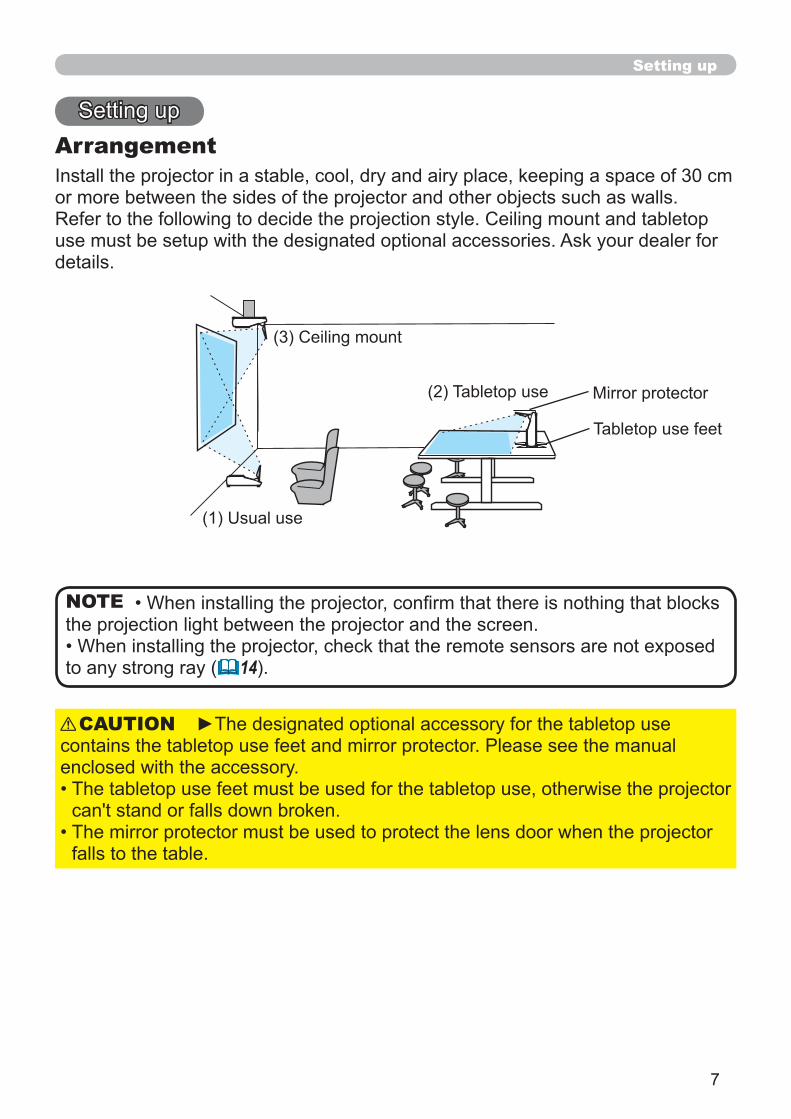
Changing the frequency of remote control signal
Using as a simple PC mouse & keyboard
USBUSB
USB
HOMEEND
ENTER
ESCRESET
WARNING
NOTE
MUTE RESETESC
46

16
LAMP
TEMP
POWER
STANDBY/ON
INPUT
Power on/off
I
18
WARNING
Turning on the power
ON 42)
NOTE
CAUTION

17
LAMP
TEMP
POWER
STANDBY/ON
INPUT
Power on/off
Turn off the power
70NOTE
CAUTION

18
VIDEO COMPUTER SEARCH
ASPECT AUTO BLANK
ON
OFF
MAGNIFY HOME PAGE UP VOLUME
END PAGE DOWN MUTE
FREEZE MY BUTTON KEYSTONE 1 2
FOCUS D-ZOOM- + - +
POSITION MENU
INPUT
MENU
VIDEO COMPUTER SEARCH
ASPECT AUTO BLANK
ON
OFF
MAGNIFY HOME PAGE UP VOLUME
END PAGE DOWN MUTE
FREEZE MY BUTTON KEYSTONE 1 2
FOCUS D-ZOOM- + - +
POSITION MENU
VIDEO COMPUTER SEARCH
ASPECT AUTO BLANK
ON
OFF
MAGNIFY HOME PAGE UP VOLUME
END PAGE DOWN MUTE
FREEZE MY BUTTON KEYSTONE 1 2
FOCUS D-ZOOM- + - +
POSITION MENU
ENTER
ESC RESET
R R
Operating
VOLUME
Adjusting the volume
VOLUME
37
MUTE
MUTE VOLUME
Temporarily muting the sound
37VIDEO S-VIDEO COMPONENT
60
INPUT
Selecting an input signal
COMPUTER
42 COMPUTERVIDEO S-VIDEO COMPONENT
COMPUTER IN1
COMPUTER
VOLUME
INPUT
MUTE
42

19
VIDEO COMPUTER SEARCH
ASPECT AUTO BLANK
ON
OFF
MAGNIFY HOME PAGE UP VOLUME
END PAGE DOWN MUTE
FREEZE MY BUTTON KEYSTONE 1 2
VIDEO COMPUTER SEARCH
ASPECT AUTO BLANK
ON
OFF
MAGNIFY HOME PAGE UP VOLUME
END PAGE DOWN MUTE
FREEZE MY BUTTON KEYSTONE 1 2
FOCUS D-ZOOM- + - +
VIDEO COMPUTER SEARCH
ASPECT AUTO BLANK
ON
OFF
MAGNIFY HOME PAGE UP VOLUME
END PAGE DOWN MUTE
FREEZE MY BUTTON KEYSTONE 1 2
Operating
VIDEO
Selecting an input signal (continued)
42VIDEO COMPUTER IN1 COMPUTER IN2
COMPONENT
ASPECTSelecting an aspect ratio
ASPECT
R R
SEARCHSearching an input signal
42
VIDEO
SEARCH
ASPECT
R R

20
OFF
END PAGE DOWN MUTE
FREEZE MY BUTTON KEYSTONE 1 2
FOCUS D-ZOOM- + - +
POSITION MENU
ENTER
ESC RESET
OFF
END PAGE DOWN MUTE
FREEZE MY BUTTON KEYSTONE 1 2
FOCUS D-ZOOM- + - +
POSITION MENU
ENTER
ESC RESET
Operating
CAUTION
COMPUTER OUTCOMPUTER IN2
COMPUTER IN1
CONTROL
LAN
AUDIOOUT
S-VIDEO
Y CB/PB CR/PR
VIDEO L
RUSB
AUDIO IN3
AUDIO IN
1
2
Adjusting the projection position
Adjusting the zoomD-ZOOM + D-ZOOM –
D-ZOOM + D-ZOOM –
D-ZOOM +
D-ZOOM –
Adjusting the picture positionPOSITION
POSITION
POSITION
22

21
OFF
END PAGE DOWN MUTE
FREEZE MY BUTTON KEYSTONE 1 2
FOCUS D-ZOOM- + - +
POSITION MENU
ENTER
ESC RESET
VIDEO COMPUTER SEARCH
ASPECT AUTO BLANK
ON
OFF
MAGNIFY HOME PAGE UP VOLUME
END PAGE DOWN MUTE
FREEZE MY BUTTON KEYSTONE 1 2
FOCUS D-ZOOM- + - +
POSITION MENU
Operating
AUTOUsing the automatic adjustment feature
34
45
AUTO
Adjusting the focus
MENU

22
VIDEO COMPUTER SEARCH
ASPECT AUTO BLANK
ON
OFF
MAGNIFY HOME PAGE UP VOLUME
END PAGE DOWN MUTE
FREEZE MY BUTTON KEYSTONE 1 2
ON
OFF
MAGNIFY HOME PAGE UP VOLUME
END PAGE DOWN MUTE
FREEZE MY BUTTON KEYSTONE 1 2
FOCUS D-ZOOM- + - +
POSITION MENU
ENTER
ESC RESET
Operating
NOTE
ON
ON
Using the magnify feature
POSITION
POSITION
Correcting the keystone distortions
51

23
VIDEO COMPUTER SEARCH
ASPECT AUTO BLANK
ON
OFF
MAGNIFY HOME PAGE UP VOLUME
END PAGE DOWN MUTE
FREEZE MY BUTTON KEYSTONE 1 2
FOCUS D-ZOOM- + - +
POSITION MENU
ENTER
VIDEO COMPUTER SEARCH
ASPECT AUTO BLANK
ON
OFF
MAGNIFY HOME PAGE UP VOLUME
END PAGE DOWN MUTE
FREEZE MY BUTTON KEYSTONE 1 2
FOCUS D-ZOOM- + - +
POSITION MENU
ENTER
Operating
BLANK
38
BLANK
Temporarily blanking the screen
44
44
NOTE
41
Freezing the screen
44
BLANK

24
VIDEO
COMPU
TER
SEAR
CH
ASPE
CT
AUTO
BLA
NK
ON
OFF
MAGNIFY
HOMEPA
GE UP
VO
LUME
END
PAGE D
OWN
MUTE
FREE
ZE
MY B
UTTON
KEY
STONE
1
2
F
OCUS
D
-ZOOM
-
+
-
+
POSIT
ION
M
ENU
ENTE
RES
C
RESET
POSITION MENU
ENTER
ESC RESET
COMPUTER OUTCOMPUTER IN2
COMPUTER IN1
CONTROL
LAN
AUDIOOUT
S-VIDEO
YCB/PB CR/PR
VIDEOL
RUSB
AUDIO IN3
AUDIO IN
1
2
LAMP
TEMP
POWER
STANDBY/ON
INPUT
MENU
FOCUS - + FOCUS
Operating
MENU
POSITION MENU
Using the menu function
MENU
RESET
ENTER MENU
ESC

25
Operating
Using the menu function (continued)
RESET
ESC
MENU
ENTER
ENTER

26
EASY MENU
Item Description
ASPECT 31
D-ZOOM 36
36
PICTURE MODE
2829

27
EASY MENU
EASY MENU (continued)
Item Description
28
CONTRAST 28
COLOR 29
TINT 29
SHARPNESS 30
36
MIRROR 36
RESET RESET
RESET
43
38
ENTER

28
PICTURE Menu
ENTER
Item Description
CONTRAST
To adjust CUSTOM
ENTER
ENTERENTER
#1 DEFAULT #1 CUSTOM #2 DEFAULT #2 CUSTOM
#3 DEFAULT
#3 CUSTOM
#5 CUSTOM #5 DEFAULT #4 CUSTOM #4 DEFAULT
#6 CUSTOM
#6 DEFAULT

29
PICTURE Menu
PICTURE Menu (continued)
Item Description
COLOR TEMP
To adjust CUSTOM
ENTER
ENTERENTER
COLOR
TINT
#2 MID CUSTOM
#3 LOW DEFAULT
#3 LOW CUSTOM
#1 HIGH DEFAULT #1 HIGH CUSTOM #2 MID DEFAULT
#6 Hi-BRIGHT-3 CUSTOM
#6 Hi-BRIGHT-3 DEFAULT
#5 Hi-BRIGHT-2 CUSTOM
#5 Hi-BRIGHT-2 DEFAULT #4 Hi-BRIGHT-1 CUSTOM #4 Hi-BRIGHT-1 DEFAULT

30
PICTURE Menu
PICTURE Menu (continued)
Item Description
SHARPNESS
ENTER
44

31
IMAGE Menu
ENTER
Item Description
ASPECT
OVER SCAN
V POSITION RESET
above

32
IMAGE Menu
IMAGE Menu (continued)
Item Description
H POSITION RESET
31
H PHASE
H SIZE
RESET
AUTO ADJUST EXECUTE
31, 32
34
45

33
INPUT Menu
ENTER
Item Description
VIDEO NR
COLOR SPACE
COMPONENT
COMPONENT( B/PB R/PR
COMPONENT ( B/PB R/PR VIDEO

34
INPUT Menu
INPUT Menu (continued)
Item DescriptionS-VIDEO VIDEO
VIDEO S-VIDEO
COMPUTER IN
COMPUTER IN1 IN2

35
INPUT Menu
INPUT Menu (continued)
Item Description
RESOLUTION
COMPUTER IN1 IN2
ENTER

36
SETUP Menu
ENTER
Item Description
D-ZOOM
51
MIRROR
51
VOLUME

37
SETUP Menu
SETUP Menu (continued)
Item Description
SPEAKER
AUDIO
VIDEO S-VIDEO COMPONENT
60

38
SCREEN Menu
ENTER
Item Description
MENU POSITION MENU
BLANK
23 BLANK
40

39
SCREEN Menu
SCREEN Menu (continued)
Item Description
START UP40
38
48

40
SCREEN Menu
SCREEN Menu (continued)
Item Description
MyScreen
ENTER
RESET ESC
ENTER
RESETESC
below
48
MyScreen Lock
48

41
SCREEN Menu
SCREEN Menu (continued)
Item Description
23
SOURCE NAME
ENTER INPUTRESET
ENTER INPUT
ENTER INPUT
ENTER INPUT
ENTER INPUT

42
OPTION Menu
ENTER
Item Description
AUTO SEARCH
AUTO ON
16
43
43
OPTION Menu
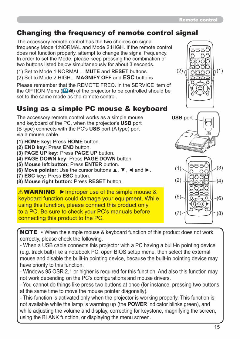
OPTION Menu (continued)
Item Description
CONTROL
17
LAMP TIME
RESET
61
RESET
63

44
OPTION Menu
OPTION Menu (continued)
Item Description2
6
R R
4659
30
2643
58
SERVICEENTER

45
OPTION Menu
OPTION Menu (continued)
Item Description
SERVICE
AUTO ADJUST
68

46
OPTION Menu
OPTION Menu (continued)
Item Description
SERVICE
REMOTE RECEIV.
ENTER INPUT
15
34

47
OPTION Menu
OPTION Menu (continued)
Item Description
4910
below
ENTER

48
OPTION Menu
OPTION Menu (continued)
Item Description
RESET
INPUT
2.1 Turning on the MyScreen

49
OPTION Menu
OPTION Menu (continued)
Item Description
ENTER
3.1 Registering the PIN Code
ENTER

50
OPTION Menu
OPTION Menu (continued)
Item Description
COMPUTER INPUT
RESET

51
OPTION Menu
OPTION Menu (continued)
Item Description
4.1 Turning On the Transition Detector
ENTER
4.2 Setting the Transition Detector
ENTER

52
OPTION Menu
OPTION Menu (continued)
Item Description
ENTER
4.3 Setting the Transition Detector off

53
Item Description
ENTER INPUTRESET
ENTERINPUT
ENTER INPUT
ENTER INPUT
ENTERINPUT
OPTION Menu
OPTION Menu (continued)

54
Item Description
ENTERINPUT
OPTION Menu
OPTION Menu (continued)

55
ENTER
NETWORK Menu
( Network Settings of
( Date/Time Settings of the User’s Manual 56
NOTE
Item Description
SETUP
ENTER
DHCP (Dynamic
Host

56
NETWORK Menu
NETWORK Menu (continued)
Item Description
SETUP
IP ADDRESS
SUBNETMASK
DNSSERVER
TIME
DATE ANDTIME
( Date/Time Settings of the

57
NETWORK Menu
NETWORK Menu (continued)
Item Description
PROJECTOR NAME
ENTER INPUT
RESET
ENTER INPUT
ENTER INPUT
ENTER INPUT
ENTER INPUT

58
NETWORK Menu
NETWORK Menu (continued)
Item Description
e-SHOT
(ENTER
To switch the image displayed
To return to the menuESC
RESET
ENTER INPUT
ESC

59
NETWORK Menu
NETWORK Menu (continued)
Item Description
57
65
SERVICE

60
C.C. (Closed Caption) Menu
Item Description
COMPONENT
MODE
CHANNEL

61
Maintenance
12, 16)
Replacing the lamp
DT00891
MENU

62
Maintenance
Replacing the lamp (continued)
About disposal of a lamp:
www.lamprecycle.orgwww.eiae.org
www.epsc.ca
WARNING
NOTE

63
Maintenance
12, 16)
MENU

64
Maintenance
WARNING
NOTE

65
Maintenance
Replacing the clock battery
HITACHI MAXELL CR2032.
OPEN
CLOSE
NOTE
WARNING
OPEN
CLOSE

66
Maintenance
COMPUTER OUTCOMPUTER IN2
COMPUTER IN1
CONTROL
LAN
AUDIOOUT
S-VIDEO
Y CB/PB CR/PR
VIDEO L
RUSB
AUDIO IN3
AUDIO IN
1
2
COMPUTER OUTCOMPUTER IN2
COMPUTER IN1
CONTROL
LAN
AUDIOOUT
S-VIDEO
Y CB/PB CR/PR
VIDEO L
RUSB
AUDIO IN3
AUDIO IN
1
2
Caring for the mirror and lens
NOTE
WARNING
CAUTION

67
Maintenance
Other care
WARNING
CAUTION
Inside of the projector

68
Troubleshooting
WARNING
Related messages
Message DescriptionThere is no input signal.
The internal temperature is rising.
43, 63

69
Troubleshooting
Regarding the indicator lampsLAMP TEMP
indicatorLAMP
indicatorTEMP
indicator Description
LightingIn Orange
Turnedoff
Turnedoff
BlinkingIn Green
Turnedoff
Turnedoff
The projector is warming up.
LightingIn Green
Turnedoff
Turnedoff
The projector is in an on state.
BlinkingIn Orange
Turnedoff
Turnedoff
The projector is cooling down.
BlinkingIn Red
(discre-tionary)
(discre-tionary)
The projector is cooling down. A certain error has
BlinkingIn Red
orLightingIn Red
LightingIn Red
Turnedoff
BlinkingIn Red
orLightingIn Red
BlinkingIn Red
Turnedoff
BlinkingIn Red
orLightingIn Red
Turnedoff
BlinkingIn Red
The cooling fan is not operating.
LightingIn Red
Turnedoff
Turnedoff
The lens door is not opened or closed properly.

70
Troubleshooting
Regarding the indicator lamps (continued)
NOTE
indicatorLAMP
indicatorTEMP
indicator Description
BlinkingIn Red
orLightingIn Red
Turnedoff
LightingIn Red
45
LightingIn Green
Simultaneousblinking in Red
LightingIn Green
Alternativeblinking in Red
Blinking in Green for approx. 3 seconds
Turnedoff
Turnedoff
projector.
Shutting the projector down
17
Resetting all settings
46
MONITOR OUT

71
Troubleshooting
Phenomena that may be easy to be mistaken for machine defects
Phenomenon Referencepage
The electrical power cord is not plugged in. 12
61
10
Signal source does not correctly work.
The BLANK function for pictures and the MUTE function for sounds are working.

72
Troubleshooting
Phenomena that may be easy to be mistaken for machine defects (continued)
Phenomenon Referencepage
10
The MUTE function is working.MUTE VOLUME 18
18
The AUDIO/SPEAKER setting is not correct. 37
The lens door is not fully opened.
10
The computer cannot detect the projector as a plug and play monitor. 11
The BLANK screen is displayed.BLANK 23

73
Troubleshooting
NOTE
Phenomena that may be easy to be mistaken for machine defects (continued)
Phenomenon Referencepage
23
Color settings are not correctly adjusted.
33
33
The whisper function is working.
The lamp is approaching the end of its product lifetime.
Either the focus and/or horizontal phase settings are not properly adjusted.
The lens or mirror is dirty or misty.66

74
Item
R R

75
356
131
366
225
378
139113
397

1
Projector
ED-A100/ED-A110/CP-A100WUser's Manual (detailed) Network Guide
Thank you for purchasing this projector.This projector has the network function that brings you the following main features.
WARNING
• The information in this manual is subject to change without notice.• The manufacturer assumes no responsibility for any errors that may appear in this manual.
NOTE
Trademark acknowledgment
Web control
e-SHOT (Still Image Transfer) Display

2
Content
About this manual..........................................................................1Content ..........................................................................................21. Main functions ...........................................................................3
........................................... 3........................................................ 3
2. Equipment connection and network setting.............................4................................................................ 4
............................................................. 52.2.1 Equipments connection ......................................................................... 5
.................................................................................... 5......................................................................... 8
.................................................................................. 93. Management with Web browser software ..............................10
.................... 113.1.1 Logon .................................................................................................. 13
............................................................................ 14................................................................................. 15
........................................................................................ 17
........................................................................................ 183 ....................................................................................... 193 ............................................................................... 21
.............................................................................. 23................................................................................. 25
............................................................................... 27................................................................................. 30................................................................................. 31
3.1.13 Logoff ................................................................................................ 313.2 E-mail Alerts.............................................................................................. 32
......................................................... 34...................................................................................... 35
...................................................... 38........................................................... 40

3
1. Main functions
1.2 e-SHOT (Still image Transfer) Display
38
1 - 4

4
2. Equipment connection and network setting
2.1 Required equipment preparation
the network.
11

5
2. Equipment connection and network setting
2.2 Manual network connection setting
2.2.1 Equipments connection
2.2.2 Network settings

6
2. Equipment connection and network setting
2.2 Manual network connection setting (continued)

7
2. Equipment connection and network setting
2.2 Manual network connection setting (continued)
[About IP address]
11
NOTE

8
2. Equipment connection and network setting
2.2 Manual network connection setting (continued)
2.2.3 “Internet Option” setting
Click
Click

9
2. Equipment connection and network setting
2.2 Manual network connection setting (continued)
2.2.4 Check connection

10
3. Management with Web browser software
11
E-mail Alerts
32
Projector Management using SNMP
34
35
e-SHOT (Still Image Transfer) Display
38
40
browser software.

11
3. Management with Web browser software
browser
NOTE

12
3. Management with Web browser software
Item Description Administrator User
Network Information
Network Settings settings.
Port Settings communication port settings.
Mail Settings
Alert Settings warning alerts.
Schedule Settings settings.
Date/Time Settings time settings.
Security Settings
Projector Control
Projector Status projector status.
Network Restart connection.

13
3. Management with Web browser software
3.1.1 Logon
“http://192.168.1.10/”
[Logon].
Example 192.168.1.10
Item ID Password<blank><blank>

14
3.1.2 Network Information
13
3. Management with Web browser software
Item DescriptionProjector NameDHCPIP AddressSubnet MaskDefault GatewayMAC Address
Firmware Date
Firmware Version

15
3. Management with Web browser software
3.1.3 Network Settings
Item Description
DHCP ONDHCP OFF
IP AddressSubnet MaskDefault Gateway
Projector Name
sysLocation (SNMP) The length of the sysLocation can be up to 255 alphanumeric
sysContact (SNMP)
DNS Server Address
[Apply]

16
3. Management with Web browser software
restart the network connection. You can restart the network connection by clicking [Network Restart] on the main menu.
NOTE

17
3. Management with Web browser software
3.1.4 Port Settings
Item DescriptionNetwork Control Port1 (Port:23)
Port open [Enable]
Authentication [Enable]this port.
Network Control Port2 (Port:9715)
Port open [Enable]
Authentication [Enable]this port.
Image Transfer Port(Port:9716)
Port open [Enable]
Authentication [Enable]for this port.
SNMP PortPort open [Enable]Trap address
SMTP PortPort open [Enable]
[Apply]
restart the network connection. You can restart the network connection by clicking [Network Restart] on the main menu.
NOTE

18
3.1.5 Mail Settings
3. Management with Web browser software
Item Description
Send mail[Enable]
SMTP Server IP Address NetworkSettingsto 255 characters.
Sender E-mail addressalphanumeric characters.
Recipient E-mail address can also specify [TO] or [CC]
characters.
[Apply]
[SendTest Mail] [Send Test Mail].
NOTE

19
3.1.6 Alert Settings
Alert Item DescriptionCover ErrorFan Error The cooling fan is not operating.
Lamp Error
Temp Error There is a possibility that the interior portion has become
Lens Door ErrorAir Flow Error The internal temperature is rising.Lamp Time Error
Cold Error There is a possibility that the interior portion has become
Filter Error
Other Error
Schedule Execution Error 21
Lamp Time AlarmFilter Time AlarmTransition Detector Alarm“CHANGE THE LAMP” is displayed.
Cold Start
Authentication Failure community.Refer to for
3. Management with Web browser software

20
3. Management with Web browser software
The Alert Items are shown below.
Setting Item Description
Alarm Time
SNMP Trap [Enable]
Send Mail [Enable]Cold Start Authentication Failure
Mail Subject The length of the subject line can be up to 255 alphanumeric characters.
Cold Start Authentication Failure
Mail Text characters.Cold Start Authentication Failure
[Apply]
sent out.
NOTE

21
3.1.7 Schedule Settings
Item DescriptionDailySundayMondayTuesdayWednesdayThursdayFridaySaturday
3. Management with Web browser software

22
3. Management with Web browser software
Item Daily & Weekly DescriptionSchedule [Enable]Schedule List
Item
Schedule [Enable]
Date (Month/Day)Schedule List
[Apply]
[Add]items.
Item DescriptionTimeCommand[Parameter]
PowerInput Source Display Image
[Register]
[Delete]
[Reset]
23
NOTE

23
3. Management with Web browser software
3.1.8 Date/Time Settings
Item DescriptionCurrent Date year/month/day format.Current Time hour:minute:second format.
Daylight Savings Time [ON]the following items.
StartMonth
Week
Day
Timehourminute
EndMonth
Week
Day
Timehourminute

24
3. Management with Web browser software
Item Description
Time differencemanager.
SNTP [ON]
SNTP Server IP Address Network
Settingsto 255 characters.
Cycle hours:minutes
[Apply]
restart the network connection. You can restart the network connection by clicking [Network Restart] on the main menu.
NOTE

25
3. Management with Web browser software
3.1.9 Security Settings
Item DescriptionAdministrator authority
Administrator IDcharacters.
AdministratorPassword characters.Re-enterAdministratorPassword
User authority
User IDcharacters.
User Passwordcharacters.
Re-enter User Password

26
3. Management with Web browser software
[Apply
restart the network connection. You can restart the network connection by clicking [Network Restart] on the main menu.
NOTE
Item Description
Network Control control.AuthenticationPasswordRe-enterAuthenticationPassword
SNMP
Community name be up to 64 alphanumeric characters.

27
3. Management with Web browser software
3.1.10 Projector Control
Item DescriptionMain
PowerInput SourcePicture ModeBlank On/OffMuteFreeze
Magnify
FocusPicture
BrightnessContrastGammaColor TempColorTintSharpnessMyMemory SaveMyMemory Recall
The items shown in the table below can be
[Refresh] button.
NOTE

28
3. Management with Web browser software
Item DescriptionImage
AspectOver ScanV PositionH PositionH PhaseH SizeAuto Adjust Execute
InputProgressiveVideo NRColor SpaceComponentC-Video FormatS-Video FormatFrame Lock-Computer1Frame Lock-Computer2Computer in-1Computer in-2
SetupD-ZoomD-Shift VD-Shift HKeystone VWhisperMirrorVolumeSpeakerAudio-Computer1Audio-Computer2Audio-ComponentAudio-S-VideoAudio-Video

29
3. Management with Web browser software
Item DescriptionScreen
LanguageMenu Position VMenu Position HBlankStartupMyScreen LockMessage
OptionAuto SearchAuto on
Auto off
My Button-1
My Button-2
Focus LockRemote Receiv. FrontRemote Receiv. TopRemote Freq. NormalRemote Freq. High
Closed CaptionDisplayModeChannel

30
3.1.11 Projector Status
3. Management with Web browser software
Item DescriptionError StatusLamp TimeFilter TimePower StatusInput StatusBlank On/OffMuteFreeze

31
3. Management with Web browser software
3.1.12 Network Restart
Item Description
Restart
[Restart] button to log on again.13
NOTE
3.1.13 LogoffWhen [Logoff] 13

32
3. Management with Web browser software
3.2 E-mail Alerts
power.
NOTE
Mail Settings ( 18)
through a web browser.
“http://192.168.1.10/”[Logon].
[Port Settings] on the main menu. [Enable][Apply]
[Mail Settings] the item 3.1.5 Mail Settings 18
[Apply]
[Send Test Mail] button in [Mail Settings]NOTE
Time <Testing time>
SMTP Port[Network Restart]
items.
NOTE

33
3.2 E-mail Alerts (continued)
3. Management with Web browser software
[Alert Settings]19
for further information.[Apply]

34
3. Management with Web browser software
3.3 Projector Management using SNMP
to use this function.
NOTE
SNMP Settings ( 17)
“http://192.168.1.10/”[Logon].
[Port Settings] on the main menu. [Enable] SNMP Port
[Security Settings] on the main menu. [SNMP]
[Alert Settings]
[Enable][Enable][Apply]
Community Name has been [Network Restart]
NOTE
SNMP Port[Network Restart]
following items.
NOTE

35
3. Management with Web browser software
21
23
NOTE

36
3. Management with Web browser software
NOTE
Schedule Settings ( 21)
“http://192.168.1.10/”[Logon].
[Schedule Settings]
select [Sunday].[Enable]
[Apply][Add]
[Register]click [Cancel] button.
[Delete]

37
3. Management with Web browser software
Daylight Savings Time or SNTP
following the instructions on replacing the battery.
NOTE
Date/Time Settings ( 23)
“http://192.168.1.10/”[Logon].
[Date/Time Settings]
[Apply]

38
3. Management with Web browser software
3.5 e-SHOT (Still Image Transfer) Display
browser. Refer to 35
NOTE
1 - 4

39
Example: If the IP address of the projector is set to 192.168.1.10:
"http://192.168.1.10/"
click [Logon].[Port Settings] on the main menu.
[Enable] ImageTransfer Port (Port: 9716) [Enable]
[Authentication] setting when
[Apply]
[Security Settings] on the main menu.[Network Control]
[Apply]
Network Control Port1 (Port: 23) Network Control Port2 (Port: 9715) Image Transfer Port (Port: 9716).
NOTE
the network connection. You can restart the network connection by clicking [Network Restart] on the main menu.
3. Management with Web browser software

40
3. Management with Web browser software
Communication Port
Command Control Settings ( 17)
“http://192.168.1.10/”[Logon].
[Port Settings] on the main menu.
[Enable] Network Control Port1 (Port: 23) to [Enable] [Authentication] setting when
[Enable] Network Control Port2 (Port: 9715) to [Enable] [Authentication] setting when
[Apply]
17NOTE

41
3. Management with Web browser software
25
[Security Settings] on the main menu. [Network Control]
[Apply]
Network Control Port1 (Port: 23), Network Control Port2 (Port: 9715) Image Transfer Port (Port: 9716).
the network connection. You can restart the network connection by clicking [Network Restart] on the main menu.
NOTE

42
3. Management with Web browser software
Command Format
Header Data length RS-232C command Check Sum ConnectionID
13 bytes 1 byte 1 byte
Reply Error code
Send Data format

43
Reply Data format
Reply ConnectionID
1 byte
Reply ConnectionID
1 byte
<Error reply>
Reply Error code ConnectionID
2 bytes 1 byte
<Projector busy reply>
<Authentication error reply>
Reply Data ConnectionID
2 bytes 1 byte
Reply Status code ConnectionID
2 bytes 1 byte
3. Management with Web browser software
Reply AuthenticationError code
ConnectionID
1 byte

44
3. Management with Web browser software
Authentication
NOTE
1
Projector
ED-A100/ED-A110/CP-A100WUser's Manual (detailed)Technical
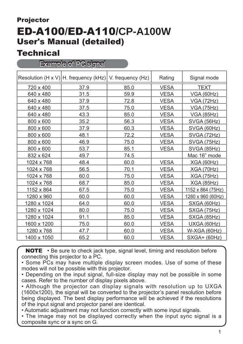
Resolution (H x V) H. frequency (kHz) V. frequency (Hz) Rating Signal mode
720 x 400 37.9 85.0 VESA TEXT640 x 480 31.5 59.9 VESA VGA (60Hz)640 x 480 37.9 72.8 VESA VGA (72Hz)640 x 480 37.5 75.0 VESA VGA (75Hz)640 x 480 43.3 85.0 VESA VGA (85Hz)800 x 600 35.2 56.3 VESA SVGA (56Hz)800 x 600 37.9 60.3 VESA SVGA (60Hz)800 x 600 48.1 72.2 VESA SVGA (72Hz)800 x 600 46.9 75.0 VESA SVGA (75Hz)800 x 600 53.7 85.1 VESA SVGA (85Hz)832 x 624 49.7 74.5 Mac 16” mode
1024 x 768 48.4 60.0 VESA XGA (60Hz)1024 x 768 56.5 70.1 VESA XGA (70Hz)1024 x 768 60.0 75.0 VESA XGA (75Hz)1024 x 768 68.7 85.0 VESA XGA (85Hz)1152 x 864 67.5 75.0 VESA 1152 x 864 (75Hz)1280 x 960 60.0 60.0 VESA 1280 x 960 (60Hz)
1280 x 1024 64.0 60.0 VESA SXGA (60Hz)1280 x 1024 80.0 75.0 VESA SXGA (75Hz)1280 x 1024 91.1 85.0 VESA SXGA (85Hz)1600 x 1200 75.0 60.0 VESA UXGA (60Hz)1280 x 768 47.7 60.0 VESA W-XGA (60Hz)
1400 x 1050 65.2 60.0 VESA SXGA+ (60Hz)
NOTE • Be sure to check jack type, signal level, timing and resolution before connecting this projector to a PC.• Some PCs may have multiple display screen modes. Use of some of these modes will not be possible with this projector.• Depending on the input signal, full-size display may not be possible in some cases. Refer to the number of display pixels above.• Although the projector can display signals with resolution up to UXGA (1600x1200), the signal will be converted to the projector’s panel resolution before being displayed. The best display performance will be achieved if the resolutions of the input signal and projector panel are identical.• Automatic adjustment may not function correctly with some input signals.• The image may not be displayed correctly when the input sync signal is a composite sync or a sync on G.
Example of PC signal

2
Initial set signals
Initial set signalsThe following signals are used for the initial settings. The signal timing of some PC models may be different. In such case, adjust the items V POSITION and H POSITION in IMAGE Menu.
computerSignal
computerSignal
Vertical signal timing (lines)(A) (B) (C) (D) (a) (b) (c) (d)
TEXT 2.0 3.0 20.3 1.0 TEXT 3 42 400 1VGA (60Hz) 3.8 1.9 25.4 0.6 VGA (60Hz) 2 33 480 10VGA (72Hz) 1.3 4.1 20.3 0.8 VGA (72Hz) 3 28 480 9VGA (75Hz) 2.0 3.8 20.3 0.5 VGA (75Hz) 3 16 480 1VGA (85Hz) 1.6 2.2 17.8 1.6 VGA (85Hz) 3 25 480 1
SVGA (56Hz) 2.0 3.6 22.2 0.7 SVGA (56Hz) 2 22 600 1SVGA (60Hz) 3.2 2.2 20.0 1.0 SVGA (60Hz) 4 23 600 1SVGA (72Hz) 2.4 1.3 16.0 1.1 SVGA (72Hz) 6 23 600 37SVGA (75Hz) 1.6 3.2 16.2 0.3 SVGA (75Hz) 3 21 600 1SVGA (85Hz) 1.1 2.7 14.2 0.6 SVGA (85Hz) 3 27 600 1Mac 16" mode 1.1 3.9 14.5 0.6 Mac 16" mode 3 39 624 1XGA (60Hz) 2.1 2.5 15.8 0.4 XGA (60Hz) 6 29 768 3XGA (70Hz) 1.8 1.9 13.7 0.3 XGA (70Hz) 6 29 768 3XGA (75Hz) 1.2 2.2 13.0 0.2 XGA (75Hz) 3 28 768 1XGA (85Hz) 1.0 2.2 10.8 0.5 XGA (85Hz) 3 36 768 11152 x 864
(75Hz) 1.2 2.4 10.7 0.6 1152 x 864 (75Hz) 3 32 864 1
1280 x 960 (60Hz) 1.0 2.9 11.9 0.9 1280 x 960
(60Hz) 3 36 960 1
SXGA (60Hz) 1.0 2.3 11.9 0.4 SXGA(60Hz) 3 38 1024 1SXGA (75Hz) 1.1 1.8 9.5 0.1 SXGA (75Hz) 3 38 1024 1SXGA (85Hz) 1.0 1.4 8.1 0.4 SXGA (85Hz) 3 44 1024 1UXGA (60Hz) 1.2 1.9 9.9 0.4 UXGA (60Hz) 3 46 1200 1W-XGA (60Hz) 1.7 2.5 16.0 0.8 W-XGA (60Hz) 3 23 768 1SXGA+ (60Hz) 1.2 2.0 11.4 0.7 SXGA+ (60Hz) 3 33 1050 1
Back porch (B) Front porch (D) Back porch (b) Front porch (d)
Active video (C)Data DataH. Sync. V. Sync.
Sync (A) Sync (a)
Active video (c)

3
MONITOR OUT COMPUTER IN2 COMPUTER IN1
CONTROL
LAN
AUDIOOUTS-VIDEO
Y CB/PB CR/PR
VIDEO L R
USB
AUDIO IN3
AUDIO IN
1
2
A COMPUTER IN1, B COMPUTER IN2, C MONITOR OUT D-sub 15pin mini shrink jack
terminated (positive)• H/V. sync. signal: TTL level (positive/negative)• Composite sync. signal: TTL level
Pin Signal Pin Signal1 Video Red 10 Ground2 Video Green 11 (No connection)3 Video Blue
12A : SDA (DDC data)B , C : (No connection)4 (No connection)
5 Ground 13 H. sync / Composite sync.6 Ground Red 14 V. sync.7 Ground Green
15A : SCL (DDC clock)B , C : (No connection)8 Ground Blue
9 (No connection) - -
Connection to the ports
Connection to the ports
B DAC
D LANRJ-45 jack
Pin Signal Pin Signal Pin Signal1 TX + 4 - 7 -2 TX - 5 - 8 -3 RX + 6 RX - - -
87654321

4
MONITOR OUT COMPUTER IN2 COMPUTER IN1
CONTROL
LAN
AUDIOOUTS-VIDEO
Y CB/PB CR/PR
VIDEO L R
USB
AUDIO IN3
AUDIO IN
1
2
Connection to the ports (continued)
4321
I VIDEORCA jack• System: NTSC, PAL, SECAM, PAL-M, PAL-N, NTSC4.43
H S-VIDEOMini DIN 4pin jack
Pin Signal
1
23 Ground4 Ground
GE
I
H
E Y, F CB/PB, G CR/PR (component video)RCA jack x3• System: 525i(480i), 525p(480p), 625i(576i), 750p(720p),1125i(1080i)
Port SignalY
CB/PB Component video CB/PB
CR/PR Component video CR/PR
F

5
MONITOR OUT COMPUTER IN2 COMPUTER IN1
CONTROL
LAN
AUDIOOUTS-VIDEO
Y CB/PB CR/PR
VIDEO L R
USB
AUDIO IN3
AUDIO IN
1
2
Connection to the ports (continued)
J AUDIO IN1, K AUDIO IN2Ø3.5 stereo mini jack
AUDIO IN3 L L, M RRCA jack x2
N AUDIO OUTØ3.5 stereo mini jack
To input SCART RGB signal; ex.:
To input SCART RGB signal to the projector, use a SCART to RCA cable. Connect the plugs refer to above ex.. For more reference, please consult your dealer.
SCART connector(jack)
SCART cable(plug)
RCA plugs
AUDIO IN3
L M
NJ
K

6
MONITOR OUT COMPUTER IN2 COMPUTER IN1
CONTROL
LAN
AUDIOOUTS-VIDEO
Y CB/PB CR/PR
VIDEO L R
USB
AUDIO IN3
AUDIO IN
1
2
Connection to the ports (continued)
O USBUSB B type jack
Pin Signal1 +5V2 - Data3 + Data4 Ground
21
34
P CONTROLD-sub 9pin plug• About the details of RS-232C communication, please refer to the following page.
Pin Signal Pin Signal Pin Signal
1 (No connection) 4 (No connection) 7 RTS2 RD 5 Ground 8 CTS3 TD 6 (No connection) 9 (No connection)
9
12345
678
OP

7
RS-232C Communication
RS-232C Communication
Connecting the cable
1. Turn off the projector and the computer.
2. Connect the CONTROL port of the projector with a RS-232C port of
3. Turn the computer on, and after the computer has started up turn the projector on.
Communications setting19200bps, 8N11. ProtocolConsist of header (7 bytes) + command data (6 bytes)2. HeaderBE + EF + 03 + 06 + 00 + CRC_low + CRC_high
3. Command dataCommand data chart
byte_0 byte_1 byte_2 byte_3 byte_4 byte_5Action Type Setting code
low high low high low highAction (byte_0 - 1)
Action Content1 Set Change setting to desired value.2 Get Read projector internal setup value.4 Increment Increment setup value by 1.5 Decrement Decrement setup value by 1.6 Execute Run a command.
6 7 8 9
1 2 3 4
5 6 7 8 9
1 2 3 4
5
CONTROL port RS-232C cable (cross) RS-232C portof the projector of the computer
- (1) (1) CDRD (2) (2) RDTD (3) (3) TD
- (4) (4) DTRGND (5) (5) GND
- (6) (6) DSRRTS (7) (7) RTSCTS (8) (8) DTS
- (9) (9) RI

8
RS-232C Communication (continued)
Requesting projector status (Get command)(1) Send the following request code from the PC to the projector. Header + Command data (‘02H’ + ‘00H’ + type (2 bytes) + ‘00H’ + ‘00H’)(2) The projector returns the response code ‘1DH’ + data (2 bytes) to the PC.Changing the projector settings (Set command)(1) Send the following setting code from the PC to the projector.
Header + Command data (‘01H’ + ‘00H’ + type (2 bytes) + setting code (2 bytes))(2) The projector changes the setting based on the above setting code.(3) The projector returns the response code ‘06H’ to the PC.Using the projector default settings (Reset Command)(1) The PC sends the following default setting code to the projector. Header + Command data (‘06H’ + ‘00H’ + type (2 bytes) + ‘00H’ + ‘00H’)
(3) The projector returns the response code ‘06H’ to the PC.Increasing the projector setting value (Increment command)(1) The PC sends the following increment code to the projector. Header + Command data (‘04H’ + ‘00H’ + type (2 bytes) + ‘00H’ + ‘00H’)(2) The projector increases the setting value on the above setting code.(3) The projector returns the response code ‘06H’ to the PC.Decreasing the projector setting value (Decrement command)(1) The PC sends the following decrement code to the projector. Header + Command data (‘05H’ + ‘00H’ + type (2 bytes) + ‘00H’ + ‘00H’)(2) The projector decreases the setting value on the above setting code.(3) The projector returns the response code ‘06H’ to the PC.When the projector cannot understand the received commandWhen the projector cannot understand the received command, the error code ‘15H’is sent back to the PC.Sometimes the projector cannot properly receive the command. In such a case, the command is not executed and the error code ‘15H’ is sent back to the PC. If this error code is returned, send the same command again.When the projector cannot execute the received command.When the projector cannot execute the received command, the error code ‘1CH’ +‘xxxxH’ is sent back to the PC. When the data length is greater than indicated by the data length code, the projector ignore the excess data code. Conversely when the data length is shorter than indicated by the data length code, an error code will be returned to the PC.
NOTEcommand or data.• Provide an interval of at least 40ms between the response code and any other code.• The projector outputs test data when the power supply is switched ON, and when the lamp is lit. Ignore this data.• Commands are not accepted during warm-up.

9
Command Control via the NetworkCommunication PortThe following two ports are assigned for the command control.
TCP #23TCP #9715
Command Control Settings
When the authentication setting is enabled, the following settings are required.
Command Control via the Network
Port Settings
Netowrk Control Port1 (Port: 23)
Port openClick the [Enable] check box to open [Network Control Port1 (Port: 23)] to use TCP #23.Default setting is “Enable”.
Authentication
Click the [Enable] check box for the [Authentication] setting when authentication is required.Default setting is “Disable”.
Network Control Port2 (Port: 9715)
Port open
Click the [Enable] check box to open [Network Control Port2 (Port: 9715)] to use TCP #9715.Default setting is “Enable”.
Authentication
Click the [Enable] check box for the [Authentication] setting when authentication is required.Default setting is “Enable”.
Security Settings
Network Control
AuthenticationPassword
Enter the desired authentication password. This setting will be the same for [NetworkControl Port1 (Port: 23)] and [NetworkControl Port2 (Port: 9715)].Default setting is blank.
Re-enterAuthenticationPassword

10
Command Control via the Network (continued)
Command Format[TCP #23]1. ProtocolConsist of header (7 bytes) + command data (6 bytes)2. HeaderBE + EF + 03 + 06 + 00 + CRC_low + CRC_high
3. Command dataCommand data chart
byte_0 byte_1 byte_2 byte_3 byte_4 byte_5Action Type Setting code
low high low high low highAction (byte_0 - 1)
Action Content1 Set Change setting to desired value.2 Get Read projector internal setup value.4 Increment Increment setup value by 1.5 Decrement Decrement setup value by 1.6 Execute Run a command.
Requesting projector status (Get command)(1) Send the following request code from the PC to the projector. Header + Command data (‘02H’ + ‘00H’ + type (2 bytes) + ‘00H’ + ‘00H’)(2) The projector returns the response code ‘1DH’ + data (2 bytes) to the PC.Changing the projector settings (Set command)(1) Send the following setting code from the PC to the projector.
Header + Command data (‘01H’ + ‘00H’ + type (2 bytes) + setting code (2 bytes))(2) The projector changes the setting based on the above setting code.(3) The projector returns the response code ‘06H’ to the PC.Using the projector default settings (Reset Command)(1) The PC sends the following default setting code to the projector. Header + Command data (‘06H’ + ‘00H’ + type (2 bytes) + ‘00H’ + ‘00H’)
(3) The projector returns the response code ‘06H’ to the PC.Increasing the projector setting value (Increment command)(1) The PC sends the following increment code to the projector. Header + Command data (‘04H’ + ‘00H’ + type (2 bytes) + ‘00H’ + ‘00H’)(2) The projector increases the setting value on the above setting code.(3) The projector returns the response code ‘06H’ to the PC.

11
Command Control via the Network (continued)
Decreasing the projector setting value (Decrement command)(1) The PC sends the following decrement code to the projector. Header + Command data (‘05H’ + ‘00H’ + type (2 bytes) + ‘00H’ + ‘00H’)(2) The projector decreases the setting value on the above setting code.(3) The projector returns the response code ‘06H’ to the PC.When the projector cannot understand the received commandWhen the projector cannot understand the received command, the error code ‘15H’is sent back to the PC.Sometimes the projector cannot properly receive the command. In such a case, the command is not executed and the error code ‘15H’ is sent back to the PC. If this error code is returned, send the same command again.When the projector cannot execute the received command.When the projector cannot execute the received command, the error code ‘1CH’ +‘xxxxH’ is sent back to the PC. When the data length is greater than indicated by the data length code, the projector ignore the excess data code. Conversely when the data length is shorter than indicated by the data length code, an error code will be returned to the PC.When authentication error occurred.When authentication errorr occurred, the error code the ‘1FH’ + ‘0400H’ is sent back to the PC.
[TCP #9715]1. ProtocolConsist of header (1 byte) + data length (1 byte) + command data (13 bytes) + check sum (1 bytes) + connection ID (1 byte).2. Header02, Fixed3. Data LengthNetwork control commands byte length (0D, Fixed)4. Command dataNetwork control commands that start with BE EF (13bytes).5. Check SumThis is the value to make zero on the addition of the lower 8 bits from the header to the check sum.6. Connection IDRandom value from 0 to 255 (This value is attached to the reply data).
NOTEcommand or data.• Provide an interval of at least 40ms between the response code and any other code.• Commands are not accepted during warm-up.

12
Command Control via the Network (continued)
7. Reply DataThe connection ID (the data is same as the connection ID data on the sending data format) is attached to the Network control commands reply data.
ACK reply: ‘06H’ + ‘xxH’NAK reply: ‘15H’ + ‘xxH’Error reply: ‘1CH’ + ‘xxxxH’ + ‘xxH’Data reply: ‘1DH’ + ‘xxxxH’ + ‘xxH’Projector busy reply: ‘1FH’ + ‘xxxxH’ + ‘xxH’Authentication error reply: ‘1FH’ + ‘0400H’ + ‘xxH’(‘xxH’ : connection ID)
Automatic Connection BreakThe TCP connection will be automatically disconnected after there is no communication for 30 seconds after being established.
AuthenticationThe projector does not accept commands without authentication success when authentication is enabled. The projector uses a challenge response type authentication with an MD5 (Message Digest 5) algorithm. When the projector is using a LAN, a random 8 bytes will be returned if authentication is enabled. Bind this received 8 bytes and the authentication password and digest this data with the MD5 algorithm and add this in front of the commands to send.
Following is a sample if the authentication password is set to “password” and the random 8 bytes are “a572f60c”.
1) Select the projector.2) Receive the random 8 bytes “a572f60c” from the projector.3) Bind the random 8 bytes “a572f60c” and the authentication password
“password” and it becomes “a572f60cpassword”.4) Digest this bind “a572f60cpassword” with MD5 algorithm.
It will be “e3d97429adffa11bce1f7275813d4bde”.5) Add this “e3d97429adffa11bce1f7275813d4bde” in front of the commands and
send the data.Send “e3d97429adffa11bce1f7275813d4bde”+command.
6) When the sending data is correct, the command will be performed and the reply data will be returned. Otherwise, an authentication error will be returned.
NOTE • As for the transmission of the second or subsequent commands, the authentication data can be omitted when the same connection.

13
Names Operation Type Header Command DataCRC Action Type Setting Code
Power Set Turn off BE EF 03 06 00 2A D3 01 00 00 60 00 00Turn on BE EF 03 06 00 BA D2 01 00 00 60 01 00
Get BE EF 03 06 00 19 D3 02 00 00 60 00 00[Example return]
00 00 01 00 02 00[Off] [On] [Cool down]
Input Source Set COMPUTER1 BE EF 03 06 00 FE D2 01 00 00 20 00 00COMPUTER2 BE EF 03 06 00 3E D0 01 00 00 20 04 00COMPONENT BE EF 03 06 00 AE D1 01 00 00 20 05 00
S-VIDEO BE EF 03 06 00 9E D3 01 00 00 20 02 00VIDEO BE EF 03 06 00 6E D3 01 00 00 20 01 00
Get BE EF 03 06 00 CD D2 02 00 00 20 00 00Error Status Get BE EF 03 06 00 D9 D8 02 00 20 60 00 00
[Example return]00 00 01 00 02 00 03 00
[Normal] [Cover error] [Fan error] [Lamp error]04 00 05 00 06 00 07 00
08 00 0C 0000[Filter error] ( F[Lens door error]ilter
RS-232C communication / Network command table
(continued on next page)
BRIGHTNESS Get BE EF 03 06 00 89 D2 02 00 03 20 00 00Increment BE EF 03 06 00 EF D2 04 00 03 20 00 00Decrement BE EF 03 06 00 3E D3 05 00 03 20 00 00
BRIGHTNESS Reset Execute BE EF 03 06 00 58 D3 06 00 00 70 00 00CONTRAST Get BE EF 03 06 00 FD D3 02 00 04 20 00 00
Increment BE EF 03 06 00 9B D3 04 00 04 20 00 00Decrement BE EF 03 06 00 4A D2 05 00 04 20 00 00
CONTRAST Reset Execute BE EF 03 06 00 A4 D2 06 00 01 70 00 00PICTURE MODE Set NORMAL BE EF 03 06 00 23 F6 01 00 BA 30 00 00
CINEMA BE EF 03 06 00 B3 F7 01 00 BA 30 01 00DYNAMIC BE EF 03 06 00 E3 F4 01 00 BA 30 04 00
BOARD(BLACK) BE EF 03 06 00 E3 EF 01 00 BA 30 20 00BOARD(GREEN) BE EF 03 06 00 73 EE 01 00 BA 30 21 00WHITEBOARD BE EF 03 06 00 83 EE 01 00 BA 30 22 00
DAYTIME BE EF 03 06 00 E3 C7 01 00 BA 30 40 00Get BE EF 03 06 00 10 F6 02 00 BA 30 00 00
[Example return] 00 00 01 00 04 00 10 00 [NORMAL] [CINEMA] [DYNAMIC] [CUSTOM] 20 00 21 00 22 00 40 00 [BOARD(BLACK) ] [BOARD(GREEN)] [WHITEBOARD] [DAY TIME]
GAMMA Set #1 DEFAULT BE EF 03 06 00 07 E9 01 00 A1 30 20 00#1 CUSTOM BE EF 03 06 00 07 FD 01 00 A1 30 10 00#2 DEFAULT BE EF 03 06 00 97 E8 01 00 A1 30 21 00#2 CUSTOM BE EF 03 06 00 97 FC 01 00 A1 30 11 00#3 DEFAULT BE EF 03 06 00 67 E8 01 00 A1 30 22 00#3 CUSTOM BE EF 03 06 00 67 FC 01 00 A1 30 12 00#4 DEFAULT BE EF 03 06 00 F7 E9 01 00 A1 30 23 00#4 CUSTOM BE EF 03 06 00 F7 FD 01 00 A1 30 13 00#5 DEFAULT BE EF 03 06 00 C7 EB 01 00 A1 30 24 00#5 CUSTOM BE EF 03 06 00 C7 FF 01 00 A1 30 14 00#6 DEFAULT BE EF 03 06 00 57 EA 01 00 A1 30 25 00#6 CUSTOM BE EF 03 06 00 57 FE 01 00 A1 30 15 00
Get BE EF 03 06 00 F4 F0 02 00 A1 30 00 00
RS-232C communication / Network command table

14
RS-232C communication / Network command table (continued)
Names Operation Type HeaderCommand Data
CRC Action Type Setting Code
User Gamma Pattern Set Off BE EF 03 06 00 FB FA 01 00 80 30 00 009 steps gray scale BE EF 03 06 00 6B FB 01 00 80 30 01 00
15 steps gray scale BE EF 03 06 00 9B FB 01 00 80 30 02 00Ramp BE EF 03 06 00 0B FA 01 00 80 30 03 00
Get BE EF 03 06 00 C8 FA 02 00 80 30 00 00User Gamma Point 1 Get BE EF 03 06 00 08 FE 02 00 90 30 00 00
Increment BE EF 03 06 00 6E FE 04 00 90 30 00 00Decrement BE EF 03 06 00 BF FF 05 00 90 30 00 00
User Gamma Point 2 Get BE EF 03 06 00 F4 FF 02 00 91 30 00 00Increment BE EF 03 06 00 92 FF 04 00 91 30 00 00Decrement BE EF 03 06 00 43 FE 05 00 91 30 00 00
User Gamma Point 3 Get BE EF 03 06 00 B0 FF 02 00 92 30 00 00Increment BE EF 03 06 00 D6 FF 04 00 92 30 00 00Decrement BE EF 03 06 00 07 FE 05 00 92 30 00 00
User Gamma Point 4 Get BE EF 03 06 00 4C FE 02 00 93 30 00 00Increment BE EF 03 06 00 2A FE 04 00 93 30 00 00Decrement BE EF 03 06 00 FB FF 05 00 93 30 00 00
User Gamma Point 5 Get BE EF 03 06 00 38 FF 02 00 94 30 00 00Increment BE EF 03 06 00 5E FF 04 00 94 30 00 00Decrement BE EF 03 06 00 8F FE 05 00 94 30 00 00
User Gamma Point 6 Get BE EF 03 06 00 C4 FE 02 00 95 30 00 00Increment BE EF 03 06 00 A2 FE 04 00 95 30 00 00Decrement BE EF 03 06 00 73 FF 05 00 95 30 00 00
User Gamma Point 7 Get BE EF 03 06 00 80 FE 02 00 96 30 00 00Increment BE EF 03 06 00 E6 FE 04 00 96 30 00 00Decrement BE EF 03 06 00 37 FF 05 00 96 30 00 00
User Gamma Point 8 Get BE EF 03 06 00 7C FF 02 00 97 30 00 00Increment BE EF 03 06 00 1A FF 04 00 97 30 00 00Decrement BE EF 03 06 00 CB FE 05 00 97 30 00 00
COLOR TEMP Set HIGH BE EF 03 06 00 0B F5 01 00 B0 30 03 00CUSTOM-1 (HIGH) BE EF 03 06 00 CB F8 01 00 B0 30 13 00
MID BE EF 03 06 00 9B F4 01 00 B0 30 02 00CUSTOM-2 (MID) BE EF 03 06 00 5B F9 01 00 B0 30 12 00
LOW BE EF 03 06 00 6B F4 01 00 B0 30 01 00CUSTOM-3 (LOW) BE EF 03 06 00 AB F9 01 00 B0 30 11 00
Hi-BRIGHT-1 BE EF 03 06 00 3B F2 01 00 B0 30 08 00CUSTOM-4 (Hi-BRIGHT-1) BE EF 03 06 00 FB FF 01 00 B0 30 18 00
Hi-BRIGHT-2 BE EF 03 06 00 AB F3 01 00 B0 30 09 00CUSTOM-5 (Hi-BRIGHT-2) BE EF 03 06 00 6B FE 01 00 B0 30 19 00
Hi-BRIGHT-3 BE EF 03 06 00 5B F3 01 00 B0 30 0A 00CUSTOM-6 (Hi-BRIGHT-3) BE EF 03 06 00 9B FE 01 00 B0 30 1A 00
Get BE EF 03 06 00 C8 F5 02 00 B0 30 00 00COLOR TEMP GAIN R Get BE EF 03 06 00 34 F4 02 00 B1 30 00 00
Increment BE EF 03 06 00 52 F4 04 00 B1 30 00 00Decrement BE EF 03 06 00 83 F5 05 00 B1 30 00 00
COLOR TEMP GAIN G Get BE EF 03 06 00 70 F4 02 00 B2 30 00 00Increment BE EF 03 06 00 16 F4 04 00 B2 30 00 00Decrement BE EF 03 06 00 C7 F5 05 00 B2 30 00 00
RS-232C communication / Network command table (continued)
(continued on next page)

15
Names Operation Type HeaderCommand Data
CRC Action Type Setting Code
COLOR TEMP GAIN B Get BE EF 03 06 00 8C F5 02 00 B3 30 00 00Increment BE EF 03 06 00 EA F5 04 00 B3 30 00 00Decrement BE EF 03 06 00 3B F4 05 00 B3 30 00 00
COLOR TEMPOFFSET R
Get BE EF 03 06 00 04 F5 02 00 B5 30 00 00Increment BE EF 03 06 00 62 F5 04 00 B5 30 00 00Decrement BE EF 03 06 00 B3 F4 05 00 B5 30 00 00
COLOR TEMPOFFSET G
Get BE EF 03 06 00 40 F5 02 00 B6 30 00 00Increment BE EF 03 06 00 26 F5 04 00 B6 30 00 00Decrement BE EF 03 06 00 F7 F4 05 00 B6 30 00 00
COLOR TEMPOFFSET B
Get BE EF 03 06 00 BC F4 02 00 B7 30 00 00Increment BE EF 03 06 00 DA F4 04 00 B7 30 00 00Decrement BE EF 03 06 00 0B F5 05 00 B7 30 00 00
COLOR Get BE EF 03 06 00 B5 72 02 00 02 22 00 00Increment BE EF 03 06 00 D3 72 04 00 02 22 00 00Decrement BE EF 03 06 00 02 73 05 00 02 22 00 00
COLOR Reset Execute BE EF 03 06 00 80 D0 06 00 0A 70 00 00TINT Get BE EF 03 06 00 49 73 02 00 03 22 00 00
Increment BE EF 03 06 00 2F 73 04 00 03 22 00 00Decrement BE EF 03 06 00 FE 72 05 00 03 22 00 00
TINT Reset Execute BE EF 03 06 00 7C D1 06 00 0B 70 00 00SHARPNESS Get BE EF 03 06 00 F1 72 02 00 01 22 00 00
Increment BE EF 03 06 00 97 72 04 00 01 22 00 00Decrement BE EF 03 06 00 46 73 05 00 01 22 00 00
SHARPNESS Reset Execute BE EF 03 06 00 C4 D0 06 00 09 70 00 00MY MEMORY Load Set 1 BE EF 03 06 00 0E D7 01 00 14 20 00 00
2 BE EF 03 06 00 9E D6 01 00 14 20 01 003 BE EF 03 06 00 6E D6 01 00 14 20 02 004 BE EF 03 06 00 FE D7 01 00 14 20 03 00
MY MEMORY Save Set 1 BE EF 03 06 00 F2 D6 01 00 15 20 00 002 BE EF 03 06 00 62 D7 01 00 15 20 01 003 BE EF 03 06 00 92 D7 01 00 15 20 02 004 BE EF 03 06 00 02 D6 01 00 15 20 03 00
PROGRESSIVE Set TURN OFF BE EF 03 06 00 4A 72 01 00 07 22 00 00TV BE EF 03 06 00 DA 73 01 00 07 22 01 00
FILM BE EF 03 06 00 2A 73 01 00 07 22 02 00Get BE EF 03 06 00 79 72 02 00 07 22 00 00
VIDEO NR Set LOW BE EF 03 06 00 26 72 01 00 06 22 01 00MID BE EF 03 06 00 D6 72 01 00 06 22 02 00
HIGH BE EF 03 06 00 46 73 01 00 06 22 03 00Get BE EF 03 06 00 85 73 02 00 06 22 00 00
ASPECT Set 4:3 BE EF 03 06 00 9E D0 01 00 08 20 00 0016:9 BE EF 03 06 00 0E D1 01 00 08 20 01 0014:9 BE EF 03 06 00 CE D6 01 00 08 20 09 00
NORMAL BE EF 03 06 00 5E DD 01 00 08 20 10 00Get BE EF 03 06 00 AD D0 02 00 08 20 00 00
RS-232C communication / Network command table (continued)
RS-232C communication / Network command table (continued)
(continued on next page)

16
Names Operation Type HeaderCommand Data
CRC Action Type Setting Code
OVER SCAN Get BE EF 03 06 00 91 70 02 00 09 22 00 00Increment BE EF 03 06 00 F7 70 04 00 09 22 00 00Decrement BE EF 03 06 00 26 71 05 00 09 22 00 00
OVER SCAN Reset Execute BE EF 03 06 00 EC D9 06 00 27 70 00 00V POSITION Get BE EF 03 06 00 0D 83 02 00 00 21 00 00
Increment BE EF 03 06 00 6B 83 04 00 00 21 00 00Decrement BE EF 03 06 00 BA 82 05 00 00 21 00 00
V POSITION Reset Execute BE EF 03 06 00 E0 D2 06 00 02 70 00 00H POSITION Get BE EF 03 06 00 F1 82 02 00 01 21 00 00
Increment BE EF 03 06 00 97 82 04 00 01 21 00 00Decrement BE EF 03 06 00 46 83 05 00 01 21 00 00
H POSITION Reset Execute BE EF 03 06 00 1C D3 06 00 03 70 00 00H PHASE Get BE EF 03 06 00 49 83 02 00 03 21 00 00
Increment BE EF 03 06 00 2F 83 04 00 03 21 00 00Decrement BE EF 03 06 00 FE 82 05 00 03 21 00 00
H SIZE Get BE EF 03 06 00 B5 82 02 00 02 21 00 00Increment BE EF 03 06 00 D3 82 04 00 02 21 00 00Decrement BE EF 03 06 00 02 83 05 00 02 21 00 00
H SIZE Reset Execute BE EF 03 06 00 68 D2 06 00 04 70 00 00AUTO ADJUST Execute BE EF 03 06 00 91 D0 06 00 0A 20 00 00COLOR SPACE Set AUTO BE EF 03 06 00 0E 72 01 00 04 22 00 00
RGB BE EF 03 06 00 9E 73 01 00 04 22 01 00SMPTE240 BE EF 03 06 00 6E 73 01 00 04 22 02 00
REC709 BE EF 03 06 00 FE 72 01 00 04 22 03 00REC601 BE EF 03 06 00 CE 70 01 00 04 22 04 00Get BE EF 03 06 00 3D 72 02 00 04 22 00 00
COMPONENT Set COMPONENT BE EF 03 06 00 4A D7 01 00 17 20 00 00SCART RGB BE EF 03 06 00 DA D6 01 00 17 20 01 00
Get BE EF 03 06 00 79 D7 02 00 17 20 00 00C-VIDEO FORMAT Set AUTO BE EF 03 06 00 A2 70 01 00 11 22 0A 00
NTSC BE EF 03 06 00 C2 74 01 00 11 22 04 00PAL BE EF 03 06 00 52 75 01 00 11 22 05 00
SECAM BE EF 03 06 00 52 70 01 00 11 22 09 00NTSC4.43 BE EF 03 06 00 62 77 01 00 11 22 02 00
M-PAL BE EF 03 06 00 C2 71 01 00 11 22 08 00N-PAL BE EF 03 06 00 32 74 01 00 11 22 07 00
Get BE EF 03 06 00 31 76 02 00 11 22 00 00S-VIDEO FORMAT Set AUTO BE EF 03 06 00 E6 70 01 00 12 22 0A 00
NTSC BE EF 03 06 00 86 74 01 00 12 22 04 00PAL BE EF 03 06 00 16 75 01 00 12 22 05 00
SECAM BE EF 03 06 00 16 70 01 00 12 22 09 00NTSC4.43 BE EF 03 06 00 26 77 01 00 12 22 02 00
M-PAL BE EF 03 06 00 86 71 01 00 12 22 08 00N-PAL BE EF 03 06 00 76 74 01 00 12 22 07 00
Get BE EF 03 06 00 75 76 02 00 12 22 00 00
RS-232C communication / Network command table (continued)
RS-232C communication / Network command table (continued)
(continued on next page)

17
Names Operation Type HeaderCommand Data
CRC Action Type Setting Code
FRAME LOCK –COMPUTER1
Set TURN OFF BE EF 03 06 00 3B C2 01 00 50 30 00 00TURN ON BE EF 03 06 00 AB C3 01 00 50 30 01 00Get BE EF 03 06 00 08 C2 02 00 50 30 00 00
FRAME LOCK –COMPUTER2
Set TURN OFF BE EF 03 06 00 0B C3 01 00 54 30 00 00TURN ON BE EF 03 06 00 9B C2 01 00 54 30 01 00Get BE EF 03 06 00 38 C3 02 00 54 30 00 00
COMPUTER IN1 Set SYNC ON G ON BE EF 03 06 00 CE D6 01 00 10 20 03 00SYNC ON G OFF BE EF 03 06 00 5E D7 01 00 10 20 02 00
Get BE EF 03 06 00 0D D6 02 00 10 20 00 00COMPUTER IN2 Set SYNC ON G ON BE EF 03 06 00 32 D7 01 00 11 20 03 00
SYNC ON G OFF BE EF 03 06 00 A2 D6 01 00 11 20 02 00Get BE EF 03 06 00 F1 D7 02 00 11 20 00 00
D-ZOOM Get BE EF 03 06 00 D0 D0 02 00 0A 30 00 00Increment BE EF 03 06 00 B6 D0 04 00 0A 30 00 00Decrement BE EF 03 06 00 67 D1 05 00 0A 30 00 00
D-ZOOM Reset Execute BE EF 03 06 00 98 C9 06 00 70 70 00 00D-SHIFT V Get BE EF 03 06 00 2C D1 02 00 0B 30 00 00
Increment BE EF 03 06 00 4A D1 04 00 0B 30 00 00Decrement BE EF 03 06 00 9B D0 05 00 0B 30 00 00
D-SHIFT V Reset Execute BE EF 03 06 00 A8 C8 06 00 74 70 00 00D-SHIFT H Get BE EF 03 06 00 58 D0 02 00 0C 30 00 00
Increment BE EF 03 06 00 3E D0 04 00 0C 30 00 00Decrement BE EF 03 06 00 EF D1 05 00 0C 30 00 00
D-SHIFT H Reset Execute BE EF 03 06 00 54 C9 06 00 75 70 00 00KEYSTONE V Get BE EF 03 06 00 B9 D3 02 00 07 20 00 00
Increment BE EF 03 06 00 DF D3 04 00 07 20 00 00Decrement BE EF 03 06 00 0E D2 05 00 07 20 00 00
KEYSTONE V Reset Execute BE EF 03 06 00 08 D0 06 00 0C 70 00 00WHISPER Set BRIGHT BE EF 03 06 00 3B 23 01 00 00 33 00 00
NORMAL BE EF 03 06 00 AB 22 01 00 00 33 01 00Get BE EF 03 06 00 08 23 02 00 00 33 00 00
MIRROR Set NORMAL BE EF 03 06 00 C7 D2 01 00 01 30 00 00H:INVERT BE EF 03 06 00 57 D3 01 00 01 30 01 00V:INVERT BE EF 03 06 00 A7 D3 01 00 01 30 02 00
H&V:INVERT BE EF 03 06 00 37 D2 01 00 01 30 03 00Get BE EF 03 06 00 F4 D2 02 00 01 30 00 00
VOLUME-COMPUTER1
Get BE EF 03 06 00 CD CC 02 00 60 20 00 00Increment BE EF 03 06 00 AB CC 04 00 60 20 00 00Decrement BE EF 03 06 00 7A CD 05 00 60 20 00 00
VOLUME-COMPUTER2
Get BE EF 03 06 00 FD CD 02 00 64 20 00 00Increment BE EF 03 06 00 9B CD 04 00 64 20 00 00Decrement BE EF 03 06 00 4A CC 05 00 64 20 00 00
VOLUME-COMPONENT
Get BE EF 03 06 00 01 CC 02 00 65 20 00 00Increment BE EF 03 06 00 67 CC 04 00 65 20 00 00Decrement BE EF 03 06 00 B6 CD 05 00 65 20 00 00
VOLUME-S-VIDEO Get BE EF 03 06 00 75 CD 02 00 62 20 00 00Increment BE EF 03 06 00 13 CD 04 00 62 20 00 00Decrement BE EF 03 06 00 C2 CC 05 00 62 20 00 00
(continued on next page)
RS-232C communication / Network command table (continued)
RS-232C communication / Network command table (continued)

18
Names Operation Type HeaderCommand Data
CRC Action Type Setting Code
VOLUME-VIDEO Get BE EF 03 06 00 31 CD 02 00 61 20 00 00Increment BE EF 03 06 00 57 CD 04 00 61 20 00 00Decrement BE EF 03 06 00 86 CC 05 00 61 20 00 00
MUTE Set TURN OFF BE EF 03 06 00 46 D3 01 00 02 20 00 00TURN ON BE EF 03 06 00 D6 D2 01 00 02 20 01 00Get BE EF 03 06 00 75 D3 02 00 02 20 00 00
SPEAKER Set TURN ON BE EF 03 06 00 FE D4 01 00 1C 20 01 00TURN OFF BE EF 03 06 00 6E D5 01 00 1C 20 00 00Get BE EF 03 06 00 5D D5 02 00 1C 20 00 00
AUDIO-COMPUTER1 Set AUDIO1 BE EF 03 06 00 6E DC 01 00 30 20 01 00AUDIO2 BE EF 03 06 00 9E DC 01 00 30 20 02 00AUDIO3 BE EF 03 06 00 0E DD 01 00 30 20 03 00Turn off BE EF 03 06 00 FE DD 01 00 30 20 00 00
Get BE EF 03 06 00 CD DD 02 00 30 20 00 00AUDIO-COMPUTER2 Set AUDIO1 BE EF 03 06 00 5E DD 01 00 34 20 01 00
AUDIO2 BE EF 03 06 00 AE DD 01 00 34 20 02 00AUDIO3 BE EF 03 06 00 3E DC 01 00 34 20 03 00Turn off BE EF 03 06 00 CE DC 01 00 34 20 00 00
Get BE EF 03 06 00 FD DC 02 00 34 20 00 00AUDIO-COMPONENT Set AUDIO1 BE EF 03 06 00 A2 DC 01 00 35 20 01 00
AUDIO2 BE EF 03 06 00 52 DC 01 00 35 20 02 00AUDIO3 BE EF 03 06 00 C2 DD 01 00 35 20 03 00Turn off BE EF 03 06 00 32 DD 01 00 35 20 00 00
Get BE EF 03 06 00 01 DD 02 00 35 20 00 00AUDIO-S-VIDEO Set AUDIO1 BE EF 03 06 00 D6 DD 01 00 32 20 01 00
AUDIO2 BE EF 03 06 00 26 DD 01 00 32 20 02 00AUDIO3 BE EF 03 06 00 B6 DC 01 00 32 20 03 00Turn off BE EF 03 06 00 46 DC 01 00 32 20 00 00
Get BE EF 03 06 00 75 DC 02 00 32 20 00 00AUDIO-VIDEO Set AUDIO1 BE EF 03 06 00 92 DD 01 00 31 20 01 00
AUDIO2 BE EF 03 06 00 62 DD 01 00 31 20 02 00AUDIO3 BE EF 03 06 00 F2 DC 01 00 31 20 03 00Turn off BE EF 03 06 00 02 DC 01 00 31 20 00 00
Get BE EF 03 06 00 31 DC 02 00 31 20 00 00REMOTE RECEIVE.
FRONTSet Off BE EF 03 06 00 FF 32 01 00 00 26 00 00
On BE EF 03 06 00 6F 33 01 00 00 26 01 00Get BE EF 03 06 00 CC 32 02 00 00 26 00 00
REMOTE RECEIVE.TOP
Set Off BE EF 03 06 00 47 33 01 00 02 26 00 00On BE EF 03 06 00 D7 32 01 00 02 26 01 00
Get BE EF 03 06 00 74 33 02 00 02 26 00 00REMOTE FREQ.
NORMALSet Off BE EF 03 06 00 FF 3D 01 00 30 26 00 00
On BE EF 03 06 00 6F 3C 01 00 30 26 01 00Get BE EF 03 06 00 CC 3D 02 00 30 26 00 00
REMOTE FREQ.HIGH
Set Off BE EF 03 06 00 03 3C 01 00 31 26 00 00On BE EF 03 06 00 93 3D 01 00 31 26 01 00
Get BE EF 03 06 00 30 3C 02 00 31 26 00 00
(continued on next page)
RS-232C communication / Network command table (continued)
RS-232C communication / Network command table (continued)

19
Names Operation Type HeaderCommand Data
CRC Action Type Setting Code
LANGUAGE Set ENGLISH BE EF 03 06 00 F7 D3 01 00 05 30 00 00FRANÇAIS BE EF 03 06 00 67 D2 01 00 05 30 01 00DEUTSCH BE EF 03 06 00 97 D2 01 00 05 30 02 00ESPAÑOL BE EF 03 06 00 07 D3 01 00 05 30 03 00ITALIANO BE EF 03 06 00 37 D1 01 00 05 30 04 00NORSK BE EF 03 06 00 A7 D0 01 00 05 30 05 00
NEDERLANDS BE EF 03 06 00 57 D0 01 00 05 30 06 00PORTUGUÊS BE EF 03 06 00 C7 D1 01 00 05 30 07 00
BE EF 03 06 00 37 D4 01 00 05 30 08 00BE EF 03 06 00 A7 D5 01 00 05 30 09 00BE EF 03 06 00 37 DE 01 00 05 30 10 00BE EF 03 06 00 57 D5 01 00 05 30 0A 00
SVENSKA BE EF 03 06 00 C7 D4 01 00 05 30 0B 00BE EF 03 06 00 F7 D6 01 00 05 30 0C 00
SUOMI BE EF 03 06 00 67 D7 01 00 05 30 0D 00POLSKI BE EF 03 06 00 97 D7 01 00 05 30 0E 00TÜRKÇE BE EF 03 06 00 07 D6 01 00 05 30 0F 00Get BE EF 03 06 00 C4 D3 02 00 05 30 00 00
MENU POSITION H Get BE EF 03 06 00 04 D7 02 00 15 30 00 00Increment BE EF 03 06 00 62 D7 04 00 15 30 00 00Decrement BE EF 03 06 00 B3 D6 05 00 15 30 00 00
MENU POSITION H Reset Execute BE EF 03 06 00 DC C6 06 00 43 70 00 00MENU POSITION V Get BE EF 03 06 00 40 D7 02 00 16 30 00 00
Increment BE EF 03 06 00 26 D7 04 00 16 30 00 00Decrement BE EF 03 06 00 F7 D6 05 00 16 30 00 00
MENU POSITION V Reset Execute BE EF 03 06 00 A8 C7 06 00 44 70 00 00BLANK Set MyScreen BE EF 03 06 00 FB CA 01 00 00 30 20 00
ORIGINAL BE EF 03 06 00 FB E2 01 00 00 30 40 00BLUE BE EF 03 06 00 CB D3 01 00 00 30 03 00
WHITE BE EF 03 06 00 6B D0 01 00 00 30 05 00BLACK BE EF 03 06 00 9B D0 01 00 00 30 06 00
Get BE EF 03 06 00 08 D3 02 00 00 30 00 00BLANK On/Off Set TURN OFF BE EF 03 06 00 FB D8 01 00 20 30 00 00
TURN ON BE EF 03 06 00 6B D9 01 00 20 30 01 00Get BE EF 03 06 00 C8 D8 02 00 20 30 00 00
START UP Set MyScreen BE EF 03 06 00 CB CB 01 00 04 30 20 00ORIGINAL BE EF 03 06 00 0B D2 01 00 04 30 00 00TURN OFF BE EF 03 06 00 9B D3 01 00 04 30 01 00Get BE EF 03 06 00 38 D2 02 00 04 30 00 00
(continued on next page)
RS-232C communication / Network command table (continued)
RS-232C communication / Network command table (continued)

20
Names Operation Type HeaderCommand Data
CRC Action Type Setting Code
MyScreen LOCK Set TURN OFF BE EF 03 06 00 3B EF 01 00 C0 30 00 00TURN ON BE EF 03 06 00 AB EE 01 00 C0 30 01 00Get BE EF 03 06 00 08 EF 02 00 C0 30 00 00
MESSAGE Set TURN OFF BE EF 03 06 00 8F D6 01 00 17 30 00 00TURN ON BE EF 03 06 00 1F D7 01 00 17 30 01 00Get BE EF 03 06 00 BC D6 02 00 17 30 00 00
AUTO SEARCH Set TURN OFF BE EF 03 06 00 B6 D6 01 00 16 20 00 00TURN ON BE EF 03 06 00 26 D7 01 00 16 20 01 00Get BE EF 03 06 00 85 D6 02 00 16 20 00 00
AUTO ON Set TURN OFF BE EF 03 06 00 3B 89 01 00 20 31 00 00TURN ON BE EF 03 06 00 AB 88 01 00 20 31 01 00Get BE EF 03 06 00 08 89 02 00 20 31 00 00
AUTO OFF Get BE EF 03 06 00 08 86 02 00 10 31 00 00Increment BE EF 03 06 00 6E 86 04 00 10 31 00 00Decrement BE EF 03 06 00 BF 87 05 00 10 31 00 00
LAMP TIME Get BE EF 03 06 00 C2 FF 02 00 90 10 00 00LAMP TIME Reset Execute BE EF 03 06 00 58 DC 06 00 30 70 00 00
FILTER TIME Get BE EF 03 06 00 C2 F0 02 00 A0 10 00 00FILER TIME Reset Execute BE EF 03 06 00 98 C6 06 00 40 70 00 00
MY BUTTON-1 COMPUTER1 BE EF 03 06 00 3A 33 01 00 00 36 00 00COMPUTER2 BE EF 03 06 00 FA 31 01 00 00 36 04 00COMPONENT BE EF 03 06 00 6A 30 01 00 00 36 05 00
S-VIDEO BE EF 03 06 00 5A 32 01 00 00 36 02 00VIDEO BE EF 03 06 00 AA 32 01 00 00 36 01 00
INFORMATION BE EF 03 06 00 FA 3E 01 00 00 36 10 00MY MEMORY BE EF 03 06 00 9A 3F 01 00 00 36 12 00
PICTURE MODE BE EF 03 06 00 0A 3E 01 00 00 36 13 00FILTER RESET BE EF 03 06 00 3A 3C 01 00 00 36 14 00
e-SHOT BE EF 03 06 00 5A 3D 01 00 00 36 16 00VOLUME + BE EF 03 06 00 CA 3C 01 00 00 36 17 00VOLUME - BE EF 03 06 00 3A 39 01 00 00 36 18 00AV MUTE BE EF 03 06 00 AA 38 01 00 00 36 19 00
Get BE EF 03 06 00 09 33 02 00 00 36 00 00
RS-232C communication / Network command table (continued)
RS-232C communication / Network command table (continued)
(continued on next page)

21
Names Operation Type HeaderCommand Data
CRC Action Type Setting Code
MY BUTTON-2 COMPUTER1 BE EF 03 06 00 C6 32 01 00 01 36 00 00COMPUTER2 BE EF 03 06 00 06 30 01 00 01 36 04 00COMPONENT BE EF 03 06 00 96 31 01 00 01 36 05 00
S-VIDEO BE EF 03 06 00 A6 33 01 00 01 36 02 00VIDEO BE EF 03 06 00 56 33 01 00 01 36 01 00
INFORMATION BE EF 03 06 00 06 3F 01 00 01 36 10 00MY MEMORY BE EF 03 06 00 66 3E 01 00 01 36 12 00
PICTURE MODE BE EF 03 06 00 F6 3F 01 00 01 36 13 00FILTER RESET BE EF 03 06 00 C6 3D 01 00 01 36 14 00
e-SHOT BE EF 03 06 00 A6 3C 01 00 01 36 16 00VOLUME + BE EF 03 06 00 36 3D 01 00 01 36 17 00VOLUME - BE EF 03 06 00 C6 38 01 00 01 36 18 00AV MUTE BE EF 03 06 00 56 39 01 00 01 36 19 00
Get BE EF 03 06 00 F5 32 02 00 01 36 00 00MAGNIFY Get BE EF 03 06 00 7C D2 02 00 07 30 00 00
Increment BE EF 03 06 00 1A D2 04 00 07 30 00 00Decrement BE EF 03 06 00 CB D3 05 00 07 30 00 00
FREEZE Set NORMAL BE EF 03 06 00 83 D2 01 00 02 30 00 00FREEZE BE EF 03 06 00 13 D3 01 00 02 30 01 00Get BE EF 03 06 00 B0 D2 02 00 02 30 00 00
e-SHOT Set OFF BE EF 03 06 00 3A C3 01 00 00 35 00 00IMAGE1 BE EF 03 06 00 AA C2 01 00 00 35 01 00IMAGE2 BE EF 03 06 00 5A C2 01 00 00 35 02 00IMAGE3 BE EF 03 06 00 CA C3 01 00 00 35 03 00IMAGE4 BE EF 03 06 00 FA C1 01 00 00 35 04 00
Get BE EF 03 06 00 09 C3 02 00 00 35 00 00e-SHOT IMAGE1 Delete Execute BE EF 03 06 00 71 C3 06 00 01 35 00 00e-SHOT IMAGE2 Delete Execute BE EF 03 06 00 35 C3 06 00 02 35 00 00e-SHOT IMAGE3 Delete Execute BE EF 03 06 00 C9 C2 06 00 03 35 00 00e-SHOT IMAGE4 Delete Execute BE EF 03 06 00 BD C3 06 00 04 35 00 00
CLOSED CAPTIONDISPLAY
Set TURN OFF BE EF 03 06 00 FA 62 01 00 00 37 00 00TURN ON BE EF 03 06 00 6A 63 01 00 00 37 01 00
AUTO BE EF 03 06 00 9A 63 01 00 00 37 02 00Get BE EF 03 06 00 C9 62 02 00 00 37 00 00
CLOSED CAPTIONMODE
Set CAPTIONS BE EF 03 06 00 06 63 01 00 01 37 00 00TEXT BE EF 03 06 00 96 62 01 00 01 37 01 00
Get BE EF 03 06 00 35 63 02 00 01 37 00 00CLOSED CAPTION
CHANNELSet 1 BE EF 03 06 00 D2 62 01 00 02 37 01 00
2 BE EF 03 06 00 22 62 01 00 02 37 02 003 BE EF 03 06 00 B2 63 01 00 02 37 03 004 BE EF 03 06 00 82 61 01 00 02 37 04 00
Get BE EF 03 06 00 71 63 02 00 02 37 00 00
RS-232C communication / Network command table (continued)
RS-232C communication / Network command table (continued)

HITACHI EUROPE LTD.
UNITED KINGDOM
Consumer Affairs DepartmentPO Box 3007MaidenheadBerkshire SL6 8ZE
Tel: 0870 405 4405Email:
HITACHI EUROPE GmbH
GERMANY
HITACHI EUROPE S.r.l.
HITACHI EUROPE S.A.S
FRANCE
Munich OfficeDornacher Strasse 3D-85622 Feldkirchen bei München
Tel: 089-991 80-0Fax: 089 - 991 80 -224Hotline: 0180 - 551 25 51 (12ct/min.)Email:
Via T. Gulli n.3920147 MILAN
Tel: 02 487861Fax: 02 48786381Servizio ClientiTel. 02 38073415Email:
Lyon OfficeB.P. 45, 69671 Bron Cedex
Tel: 04 72 14 29 70Fax: 04 72 14 29 99Email:
ITALY
HITACHI EUROPE S.A.
GREECE
HITACHI EUROPE S.A.
HITACHI EUROPE AB
SWEDEN
HITACHI EUROPE LTD.
NORWAY
364, Kifissias Ave. & 1, Delfon Str.152 33 ChalandriAthens
Tel: 1-6837200Fax: 1-6835694Email:
Gran Via Carles III, 86 Planta 5ªEdificios Trade - Torre Este08028 Barcelona
Tel: 93 409 2550Fax: 93 491 3513Email:
Box 77S-164 94 KISTA
Tel: 08 562 711 00Fax: 08 562 711 11Email:
Norwegian Branch OfficeStrandveien 181366 Dysaker
Tel: 02205 9060Fax: 02205 9061Email
SPAIN
HITACHI EUROPE LTD.
BELGIUM
Benelux Branche OfficeBergensesteenweg 4211600 Sint-Pieters-Leeuw
TEL : 0032/2 363 99 01FAX: 0032/2 363 99 00Email : [email protected]
www.hitachidigitalmedia.com
Hitachi, Ltd.Consumer Business Group
Shin-Otemachi Bldg 5f, 2-1, Otemachi 2-Chome,Chiyoda-Ku, Tokyo 100-0004 Japan