Ecuaciones Generales de Deflexiones en Vigas...
57
ANALYSIS, DESIGN AND CONSTRUCTION OF ARCH BRIDGES © 2002, 2003 OSCAR MUROY 0 CONTENTS 1. EFFECTS OF CURVATURE ON THE STRESS-DEFORMATION EQUATIONS IN THE CROSS SECTION OF A CURVED BEAM 2. GENERAL EQUATIONS OF DEFLECTIONS IN A CURVED BEAM 3. DIRECTRIX OF THE ARCH 4. DEPTH VARIATION OF THE ARCH 5. TYPICAL CONFIGURATIONS OF ARCH BRIDGES 6. CONSTRUCTION PROCEDURES OF ARCH BRIDGES 7. SECOND ORDER DEFLECTIONS IN ARCHES 8. COMPENSATING TECHNIQUES ON ARCHES 9. ARCH STABILITY 10. TEMPERATURE VARIATION, CONCRETE SHRINKAGE AND SUPPORT DISPLACEMENT EFFECTS 11. GEOMETRY CONTROL OF THE ARCH DURING CONSTRUCTION 12. BIBLIOGRAPHY Conference Themes at the Instituto de la Construcción y Gerencia: “Análisis y Diseño de Puentes en Arco”, June 2,002 “Concepción Estructural de Puentes en Arco”, August 2,003 Published in the Journal of the ICG, N° PT-09 y PT-21, respectively
-
Upload
dangnguyet -
Category
Documents
-
view
212 -
download
0
Transcript of Ecuaciones Generales de Deflexiones en Vigas...

ANALYSIS, DESIGN AND CONSTRUCTION OF ARCH BRIDGES
© 2002, 2003 OSCAR MUROY 0
CONTENTS
1. EFFECTS OF CURVATURE ON THE STRESS-DEFORMATION EQUATIONS IN THE
CROSS SECTION OF A CURVED BEAM
2. GENERAL EQUATIONS OF DEFLECTIONS IN A CURVED BEAM
3. DIRECTRIX OF THE ARCH
4. DEPTH VARIATION OF THE ARCH
5. TYPICAL CONFIGURATIONS OF ARCH BRIDGES
6. CONSTRUCTION PROCEDURES OF ARCH BRIDGES
7. SECOND ORDER DEFLECTIONS IN ARCHES
8. COMPENSATING TECHNIQUES ON ARCHES
9. ARCH STABILITY
10. TEMPERATURE VARIATION, CONCRETE SHRINKAGE AND SUPPORT
DISPLACEMENT EFFECTS
11. GEOMETRY CONTROL OF THE ARCH DURING CONSTRUCTION
12. BIBLIOGRAPHY
Conference Themes at the Instituto de la Construcción y Gerencia:
“Análisis y Diseño de Puentes en Arco”, June 2,002
“Concepción Estructural de Puentes en Arco”, August 2,003
Published in the Journal of the ICG, N° PT-09 y PT-21, respectively

ANALYSIS, DESIGN AND CONSTRUCTION OF ARCH BRIDGES
© 2002, 2003 OSCAR MUROY 1
1. EFFECTS OF CURVATURE ON THE STRESS-DEFORMATION EQUATIONS IN
THE CROSS SECTION OF A CURVED BEAM
In a straight beam as well as in a curved axis beam, it has been proved, by model testing and
verified by a rigorous analysis using the Theory of Elasticity, that cross sections initially plane,
remain plane after being subjected to axial forces and moments.
Let a segment of a curved beam with AB axis,
with a radius of curvature R and a subtended
angle d (Fig. N° 1.1)
The total deformation could be divided in an
axial deformation ds and an angular
deformation d.
Then, in the fibre a distance y from the axis,
total deformation will be:
dyds
And the original length is dyR
Hence stress will be:
dyR
dydsEE
(1.1)
Fig 1.1
a) Section subjected to an axial force N:
In this case we will have the equations
0 MdAyA (1.2)
NdAA
(1.3)
The Moment of Inertia of the cross section is defined as:
AdAyI
2,
And doing:
dA
R
y
yI
A
1
'2
,
Being the value y/R, normally very small, developing in series of (y/R) and neglecting
larger terms to 3th order, we get the following expression:
2
1
1
R
IAdA
R
yA

ANALYSIS, DESIGN AND CONSTRUCTION OF ARCH BRIDGES
© 2002, 2003 OSCAR MUROY 2
Using these expressions and the Eq. (1.1) in developing the Eq. (1.2), we obtain the
relation of axial and angular deformation:
R
ds
I
Id
' (1.4)
Replacing this Eq. (1.4) in the Eq. (1.3), and taking into account that:
dRds , segment of the curved beam axis
Axial deformation will be: dsEA
Nds
(1.5)
And replacing Eq. (1.5) in the Eq. (1.4), we obtain the angular deformation:
dsEAR
N
I
Id
'
(1.6)
Replacing Eq. (1.5) and (1.6) in the Eq. (1.1), we obtain the axial stress:
A
N
b) Cross section subjected to a bending moment M:
In this case we have the equations:
0 NdAA (1.7)
MdAyA
(1.8)
From Eq. (1.7), with the same assumptions as before, we obtain the relation between
angular deformation and axial deformation:
R
ds
AR
I
I
ARd
2
2
1 (1.9)
Replacing Eq. (1.9) in the Eq. (1.8), we obtain the axial deformation:
dsEAR
M
I
Ids
'
(1.10)
Replacing this value, in the Eq. (1.9) we obtain the angular deformation:
dsAR
I
EI
Md
21
'
(1.11)
Lastly, replacing these two values in Eq. (1.1), we obtain the bending stress, in the cross
section:
R
yI
My
I
I
AR
M
I
I
R
y
y
I
M
AR
M
I
I
1
1
''1
'' ,
Hence, in the curved element, we will have axial stresses in the neutral axis of the cross
section, due to a bending moment M:

ANALYSIS, DESIGN AND CONSTRUCTION OF ARCH BRIDGES
© 2002, 2003 OSCAR MUROY 3
AR
M
I
I
'
c) Section subjected to shearing force T:
In this case we will get a shearing strain equal to :
ds
GA
Tds
AG
Tds
GA
Tdy
1/
Making /1 AA , equivalent area to shear force,
being k, a factor depending on the sectional shape.
Fig 1.2
d) Summary:
Then for a section subjected to M, N and T, we will get the following deformations:
Angular deformations:
dsEAR
N
I
I
AR
I
EI
M
I
Ids
EAR
N
I
Ids
AR
I
EI
Md
'1
''1
' 22
(1.12)
Axial deformations:
dsEAR
M
I
I
EA
Nds
' (1.13)
Shearing deformations:
(1.14)
In Eq. (1.12) and (1.13), second terms EAR
N
I
I
' and
EAR
M
I
I
', are the effects of curvature in
the deformations of a curved beam
Next we have a table with the values for areas, inertia and the parameters I / I’, I / I’ ( 1+ I /
AR2
), I / I’ ( I / AR2
) y A / A1:
Section A I I’/I
21
' AR
I
I
I 2
' AR
I
I
I A/A1
Rectangular
bxh bh 3
12
1bh
2
2031
Rh
2
1511
Rh 2
121
Rh 3/2
Box
bxh - b1xh1 11hbbh 3
11
3
12
1hbbh
3
11
3
5
11
5
220
31hbbh
hbbh
R *
11
3
11
3
212
1
hbbh
hbbh
R
Circular
h
2
4
1h
4
64
1h
2
811
Rh
2
1611
Rh 2
161
Rh 4/3
dsGA
Tyd
1

ANALYSIS, DESIGN AND CONSTRUCTION OF ARCH BRIDGES
© 2002, 2003 OSCAR MUROY 4
Tubular
h y h1
2
1
2
4
1hh 4
1
4
64
1hh
2
1
2
4
1
2
1
24
28
11hh
hhhh
R
2
1
2
4
1
4
216
11hh
hh
R 2
1
2
216
1 hhR
*
11
3
11
3
23
11
3
5
11
5
212
120
31hbbh
hbbh
Rhbbh
hbbh
R
Table 1.1 Typical Cross Section Parameters
In order to have an idea of the values (h/R), we refer to tables N° 1.2 and N° 1.3 and we can
see that in concrete Arch Bridges, it is between 1/30 to 1/70 and 1/50 to >1/100 in Steel Arch
Bridges. Then (h/R)2
<1/900~1/10,000 and therefore very small comparing to1.
N° Bridge
Name Type
Span
l(m)
Rise
f(m) l/f Directrix
hs
(m) hs/l
hc
(m) hc/l
Cross
Section
1 Nant Ffrwd built-in 64.9 7.9 8.2 parab. 0.89 1/72.9 0.61 1/106.4 rectang.
2 Kimitsu built-in 66 14.9 4.4 1.8 1/36.7 1.2 1/55 Hollow
3 Mannen Two-hinged 79 10.6 7.5 2.1 1/37.6 2.1 1/37.6 rectang.
4 Omokage built-in 85.0 17.0 5 cos hip 2.1 1/40.5 1.5 1/56.7 Box
5 Nant Hir built-in 85.5 11.3 7.6 parab. 0.91 1/93.9 0.61 1/140.2 rectang.
6 Araya built-in 88 15.0 5.9 2.4 1/36.7 1.5 1/58.7 Box
7 Yoshimi built-in 90.0 18.0 5 cos hip 2.7 1/33.3 1.7 1/52.9 Box
8 Miyakawa built-in 92 17.0 5.4 cos hip 2.0 1/46 1.5 1/61.3 rect
hollow
9 Taf Fechan built-in 119.5 11.4 10.5 parab. 1.1 1/108.6 0.76 1/157.2 rectang.
10 Yumeno built-in 124.0 18.0 6.9 2.5 1/49.6 1.8 1/68.9
11 Taishaku built-in 145.0 30.0 4.8 cos hip 3.8 1/38.2 2.4 1/60.4 Box
12 Hokawazu Two-hinged 170.0 26.5 6.4 parab 4th
o 3.0 1/56.7 2.4 1/70.8 Box
13 Beppu
Myoban
built-in 235.0 35.5 6.6 4.5 1/52.2 3.5 1/67.1 Box
14 Río Paraná built-in 290.0 53.0 5.5 4.8 1/60.4 3.20 1/90.6 Box
15 Gladesville built-in 304.8 40.8 7.5 6.9 1/44.2 4.3 1/70.9 Box
Table 1.2 Concrete Arch Bridges
N° Bridge
Name Type
Span
l(m)
Rise
f(m) l/f Directrix
hs
(m) hs/l
hc
(m) hc/l
Cross
Section
1 South Street Two-hinged 58.8 8.8 6.7 circular 1.00 1/58.8 1.00 1/58.8 box
2 Northfolk Two-hinged 84.1 15.5 5.4 parab. 0.61 1/138.0 0.61 1/138.0 box

ANALYSIS, DESIGN AND CONSTRUCTION OF ARCH BRIDGES
© 2002, 2003 OSCAR MUROY 5
3 New
Scotswood
Two-hinged 100.0 19.5 5.1 0.76 1/131.6 0.76 1/131.6 box
4 Leavenworth Two-hinged 128.0 24.4 5.2 0.85 1/150.6 0.85 1/150.6 box
5 Smith Av. Two-hinged 158.5 33.3 4.8 2.44 1/65.0 2.44 1/65.0 box
6 Río
Colorado
built-in 167.6 27.4 6.1 2.13 1/78.7 2.13 1/78.7 box
7 Cold Spring Two-hinged 213.4 36.3 5.9 2.74 1/77.9 2.74 1/77.9 box
8 Glenfield Two-hinged 228.6 37.9 6.0 1.22 1/187.4 1.22 1/187.4 box
9 Fort Pitt Two-hinged 228.6 37.2 6.1 1.64 1/139.4 1.64 1/139.4 box
10 Lewiston built-in 304.8 48.5 6.3 parab 4th
o 4.13 1/73.8 4.13 1/73.8 box
11 Roosevelt built-in 329.2 70.1 4.7 parab. 6.1 1/54 2.44 1/135.2 box
12 Vltava
Valley
Two-hinged 330.0 42.5 7.8 5.0 1/66 5.0 1/66 box
13 Fremont Two-hinged 382.5 103.9 3.7 1.22 1/313.7 1.22 1/313.7 box
Table 1.3 Steel Arch Bridges

ANALYSIS, DESIGN AND CONSTRUCTION OF ARCH BRIDGES
© 2002, 2003 OSCAR MUROY 6
2. GENERAL EQUATIONS OF DEFLECTIONS IN CURVED BEAMS
Fig 2.1
The Navier-Bresse Equations for the displacements in curved beams are given by:
Angular Displacement:
dsEI
Mww
s
s
0
0 (2.1)
Horizontal Displacement:
dsGA
Tds
EA
Ndsy
EI
Myywuu
s
s
s
s
s
s
sincos
0001
000 (2.2)
Vertical Displacement:
dsGA
Tds
EA
Ndsx
EI
Mxxwvv
s
s
s
s
s
s
cossin
0001
000 (2.3)
where:
dsEI
Md , is the angular deformation in a segment ds of the arch
dsEA
Nds , axial deformation
dsGA
Tdy
1
, shear deformation
In these equations it is not considered the effects of curvature of the arch
Then, to take into account these effects, we should substitute these values, with the values:
dsEAR
N
I
I
AR
I
I
I
EI
Md
'1
' 2 (2.4)
dsEAR
M
I
I
EA
Nds
' (2.5)

ANALYSIS, DESIGN AND CONSTRUCTION OF ARCH BRIDGES
© 2002, 2003 OSCAR MUROY 7
dsGA
Tdy
1
(2.6)
The axis curvature, is obtained from the equation:
3
2/322/32
cos"1
"
'1
"1y
tg
y
y
y
R
(2.7)
Developing first the Navier-Bresse equations, we have:
dsEI
Mww
s
s
0
0 (2.8)
dsGA
Tds
EA
Nds
EI
Mywywuu
s
s
s
s
s
s
sincos
0001
000 (2.9)
dsGA
Tds
EA
Nds
EI
Mxwxwvv
s
s
s
s
s
s
cossin
0001
000 (2.10)
Replacing Eq. (2.4) in Eq. (2.8):
dsEAR
N
I
I
AR
I
I
I
EI
Mww
s
s
0'
1'
20
This Eq. could be written as follows:
dsM
NR
AR
I
I
I
AR
I
I
I
EI
Mww
s
s
0
220'
1'
(2.11)
Replacing Eq. (2.4) and (2.5) in Eq. (2.9):
dsEAR
N
I
I
AR
I
I
I
EI
Mywywuu
s
s
0'
1'
2000
s
s
s
s
dsGA
Tds
EAR
M
I
I
EA
N
00
sincos' 1
This Eq. could be written as follows:
dsR
AR
I
I
I
AR
I
I
I
EI
Mywywuu
s
s
0
cos
'1
'22000
s
s
s
s
dsGA
Tds
RI
I
EA
N
00
sincos'
1cos1
(2.12)
Replacing Eq. (2.4) and (2.5) in Eq. (2.10):

ANALYSIS, DESIGN AND CONSTRUCTION OF ARCH BRIDGES
© 2002, 2003 OSCAR MUROY 8
dsEAR
N
I
I
AR
I
I
I
EI
Mxwxwvv
s
s
0'
1'
2000
s
s
s
s
dsGA
Tds
EAR
M
I
I
EA
N
00
cossin' 1
This Eq. could be written as follows:
dsR
AR
I
I
I
AR
I
I
I
EI
Mxwxwvv
s
s
0
sin
'1
'22000
s
s
s
s
dsGA
Tds
RI
I
EA
N
00
cossin'
1sin1
(2.13)
Doing:
21
' AR
I
I
I
2' AR
I
I
I
cosR
sinR
Lastly, we have the equations:
dsM
NR
EI
Mww
s
s
0
0 (2.14)
dsEI
Mywywuu
s
s
0
000
s
s
s
s
dsGA
Tds
I
I
EA
N
00
sin'
1cos1
(2.15)
dsEI
Mxwxwvv
s
s
0
000
s
s
s
s
dsGA
Tds
I
I
EA
N
00
cos'
1sin1
(2.16)

ANALYSIS, DESIGN AND CONSTRUCTION OF ARCH BRIDGES
© 2002, 2003 OSCAR MUROY 9
It has been examined the values of parameters , , and , for two typical cases: built-in
arch of 65 m span and two-hinged arch of 92 m span, whence the following conclusions could
be drawn for these parameters
00.1
00.0
00.1
00.1
00.2)´
(1 I
I
20.1)´
(1 I
I
Lastly the Navier equations could be written, taking into account the curvature effects, in the
following way:
dsEI
Mww
s
s
0
0 (2.17)
s
s
s
s
s
s
dsGA
Tds
EA
Nds
EI
Mywywuu
000
sincos20.11
000 (2.18)
s
s
s
s
s
s
dsGA
Tds
EA
Nds
EI
Mxwxwvv
000
cossin0.21
000 (2.19)
That is, the effect of curvature could be incorporated in the normal Navier equations,
modifying the value of the section area for the axial force, with a reduction factor of 0,8 and
0,5 in the equations of horizontal and vertical deflections, respectively.
In the practice, this could be done, calculating the results for each of these values of reduced
area to axial force, with the final result lying in between these two values

ANALYSIS, DESIGN AND CONSTRUCTION OF ARCH BRIDGES
© 2002, 2003 OSCAR MUROY 10
Arch, parabolic axis, two-hinged, parabolic variation of h
x y h cos 0 sin 0 y" R I/I´
-46.000 0.000 1.500 0.8042 0.5944 -0.0161 -119.6694 1.0000 1.0000 0.0000
-41.400 3.230 1.595 0.8326 0.5539 -0.0161 -107.8244 1.0000 1.0000 0.0000
-36.800 6.120 1.680 0.8608 0.5090 -0.0161 -97.5807 1.0000 1.0000 0.0000
-32.200 8.670 1.755 0.8882 0.4595 -0.0161 -88.8297 0.9999 1.0000 0.0000
-27.600 10.880 1.820 0.9141 0.4054 -0.0161 -81.4704 0.9999 1.0000 0.0000
-23.000 12.750 1.875 0.9380 0.3467 -0.0161 -75.4112 0.9999 1.0000 0.0001
-18.400 14.280 1.920 0.9590 0.2835 -0.0161 -70.5711 0.9999 1.0000 0.0001
-13.800 15.470 1.955 0.9763 0.2165 -0.0161 -66.8813 0.9999 0.9999 0.0001
-9.200 16.320 1.980 0.9892 0.1462 -0.0161 -64.2864 0.9999 0.9999 0.0001
-4.600 16.830 1.995 0.9973 0.0737 -0.0161 -62.7460 0.9998 0.9999 0.0001
0.000 17.000 2.000 1.0000 0.0000 -0.0161 -62.2353 0.9998 0.9999 0.0001
4.600 16.830 1.995 0.9973 -0.0737 -0.0161 -62.7460 0.9998 0.9999 0.0001
9.200 16.320 1.980 0.9892 -0.1462 -0.0161 -64.2864 0.9999 0.9999 0.0001
13.800 15.470 1.955 0.9763 -0.2165 -0.0161 -66.8813 0.9999 0.9999 0.0001
18.400 14.280 1.920 0.9590 -0.2835 -0.0161 -70.5711 0.9999 1.0000 0.0001
23.000 12.750 1.875 0.9380 -0.3467 -0.0161 -75.4112 0.9999 1.0000 0.0001
27.600 10.880 1.820 0.9141 -0.4054 -0.0161 -81.4704 0.9999 1.0000 0.0000
32.200 8.670 1.755 0.8882 -0.4595 -0.0161 -88.8297 0.9999 1.0000 0.0000
36.800 6.120 1.680 0.8608 -0.5090 -0.0161 -97.5807 1.0000 1.0000 0.0000
41.400 3.230 1.595 0.8326 -0.5539 -0.0161 -107.8244 1.0000 1.0000 0.0000
46.000 0.000 1.500 0.8042 -0.5944 -0.0161 -119.6694 1.0000 1.0000 0.0000
Span=92.00m, rise=17.00m, hc=2.00m, ha=1.50m
+/ (+/) -/ (-/) 1+(I/I´)
1-
(I/I´)
-46.000 0.000 -0.0104 0.6467 1.0000 -46.0004 1.0012 0.0000 1.6467 1.0104
-41.400 3.230 -0.0360 0.6932 1.0000 -41.4005 1.0005 3.2316 1.6932 1.0360
-36.800 6.120 -0.0729 0.7409 1.0000 -36.8005 1.0003 6.1220 1.7409 1.0729
-32.200 8.670 -0.1099 0.7888 1.0000 -32.2005 1.0003 8.6723 1.7888 1.1099
-27.600 10.880 -0.1461 0.8357 1.0000 -27.6005 1.0003 10.8827 1.8356 1.1461
-23.000 12.750 -0.1802 0.8798 1.0000 -23.0004 1.0002 12.7531 1.8798 1.1802
-18.400 14.280 -0.2110 0.9196 1.0000 -18.4003 1.0002 14.2835 1.9195 1.2110
-13.800 15.470 -0.2369 0.9531 1.0000 -13.8002 1.0002 15.4738 1.9530 1.2369
-9.200 16.320 -0.2566 0.9786 1.0000 -9.2002 1.0002 16.3240 1.9785 1.2566
-4.600 16.830 -0.2690 0.9946 1.0000 -4.6001 1.0002 16.8341 1.9944 1.2689
0.000 17.000 -0.2732 1.0000 1.0000 0.0000 1.0002 17.0042 1.9998 1.2731
4.600 16.830 -0.2690 0.9946 1.0000 4.6001 1.0002 16.8341 1.9944 1.2689
9.200 16.320 -0.2566 0.9786 1.0000 9.2002 1.0002 16.3240 1.9785 1.2566
13.800 15.470 -0.2369 0.9531 1.0000 13.8002 1.0002 15.4738 1.9530 1.2369
18.400 14.280 -0.2110 0.9196 1.0000 18.4003 1.0002 14.2835 1.9195 1.2110
23.000 12.750 -0.1802 0.8798 1.0000 23.0004 1.0002 12.7531 1.8798 1.1802
27.600 10.880 -0.1461 0.8357 1.0000 27.6005 1.0003 10.8827 1.8356 1.1461
32.200 8.670 -0.1099 0.7888 1.0000 32.2005 1.0003 8.6723 1.7888 1.1099
36.800 6.120 -0.0729 0.7409 1.0000 36.8005 1.0003 6.1220 1.7409 1.0729
41.400 3.230 -0.0360 0.6932 1.0000 41.4005 1.0005 3.2316 1.6932 1.0360
46.000 0.000 -0.0104 0.6467 1.0000 46.0004 1.0012 0.0000 1.6467 1.0104
38.8605
24.3307
1.8505 1.1586

ANALYSIS, DESIGN AND CONSTRUCTION OF ARCH BRIDGES
© 2002, 2003 OSCAR MUROY 11
Arch, parabolic axis 4th order, two-hinged, parabolic variation of h
x y h cos 0 sin 0 y" R I/I´
-46.000 0.000 1.500 0.8140 0.5809 -0.0133 -139.4380 1.0000 1.0000 0.0000
-41.400 3.140 1.595 0.8381 0.5456 -0.0139 -121.9665 1.0000 1.0000 0.0000
-36.800 5.985 1.680 0.8629 0.5053 -0.0145 -107.3676 1.0000 1.0000 0.0000
-32.200 8.524 1.755 0.8880 0.4598 -0.0150 -95.2398 0.9999 1.0000 0.0000
-27.600 10.745 1.820 0.9127 0.4087 -0.0154 -85.2713 0.9999 1.0000 0.0000
-23.000 12.640 1.875 0.9360 0.3519 -0.0158 -77.2158 0.9999 1.0000 0.0000
-18.400 14.201 1.920 0.9571 0.2896 -0.0161 -70.8774 0.9999 1.0000 0.0001
-13.800 15.422 1.955 0.9750 0.2223 -0.0163 -66.1026 0.9999 0.9999 0.0001
-9.200 16.297 1.980 0.9886 0.1508 -0.0165 -62.7742 0.9999 0.9999 0.0001
-4.600 16.824 1.995 0.9971 0.0762 -0.0166 -60.8101 0.9998 0.9999 0.0001
0.000 17.000 2.000 1.0000 0.0000 -0.0166 -60.1608 0.9998 0.9999 0.0001
4.600 16.824 1.995 0.9971 -0.0762 -0.0166 -60.8101 0.9998 0.9999 0.0001
9.200 16.297 1.980 0.9886 -0.1508 -0.0165 -62.7742 0.9999 0.9999 0.0001
13.800 15.422 1.955 0.9750 -0.2223 -0.0163 -66.1026 0.9999 0.9999 0.0001
18.400 14.201 1.920 0.9571 -0.2896 -0.0161 -70.8774 0.9999 1.0000 0.0001
23.000 12.640 1.875 0.9360 -0.3519 -0.0158 -77.2158 0.9999 1.0000 0.0000
27.600 10.745 1.820 0.9127 -0.4087 -0.0154 -85.2713 0.9999 1.0000 0.0000
32.200 8.524 1.755 0.8880 -0.4598 -0.0150 -95.2398 0.9999 1.0000 0.0000
36.800 5.985 1.680 0.8629 -0.5053 -0.0145 -107.3676 1.0000 1.0000 0.0000
41.400 3.140 1.595 0.8381 -0.5456 -0.0139 -121.9665 1.0000 1.0000 0.0000
46.000 0.000 1.500 0.8140 -0.5809 -0.0133 -139.4380 1.0000 1.0000 0.0000
Span=92.00m, rise=17.00m, hc=2.00m, ha=1.50m
+/ (+/) -/ (-/) 1+(I/I´)
1-
(I/I´)
-46.000 0.000 -0.0088 0.5679 1.0000 -46.0004 1.0011 0.0000 1.5679 1.0088
-41.400 3.140 -0.0307 0.6222 1.0000 -41.4005 1.0005 3.1412 1.6221 1.0307
-36.800 5.985 -0.0646 0.6783 1.0000 -36.8005 1.0003 5.9867 1.6782 1.0646
-32.200 8.524 -0.1008 0.7353 1.0000 -32.2005 1.0003 8.5257 1.7353 1.1008
-27.600 10.745 -0.1381 0.7920 1.0000 -27.6005 1.0002 10.7476 1.7920 1.1381
-23.000 12.640 -0.1749 0.8465 1.0000 -23.0004 1.0002 12.6431 1.8464 1.1749
-18.400 14.201 -0.2093 0.8964 1.0000 -18.4004 1.0002 14.2047 1.8963 1.2093
-13.800 15.422 -0.2393 0.9391 1.0000 -13.8003 1.0002 15.4258 1.9390 1.2393
-9.200 16.297 -0.2626 0.9720 1.0000 -9.2002 1.0002 16.3016 1.9719 1.2626
-4.600 16.824 -0.2775 0.9929 1.0000 -4.6001 1.0003 16.8284 1.9927 1.2774
0.000 17.000 -0.2826 1.0000 1.0000 0.0000 1.0003 17.0043 1.9998 1.2825
4.600 16.824 -0.2775 0.9929 1.0000 4.6001 1.0003 16.8284 1.9927 1.2774
9.200 16.297 -0.2626 0.9720 1.0000 9.2002 1.0002 16.3016 1.9719 1.2626
13.800 15.422 -0.2393 0.9391 1.0000 13.8003 1.0002 15.4258 1.9390 1.2393
18.400 14.201 -0.2093 0.8964 1.0000 18.4004 1.0002 14.2047 1.8963 1.2093
23.000 12.640 -0.1749 0.8465 1.0000 23.0004 1.0002 12.6431 1.8464 1.1749
27.600 10.745 -0.1381 0.7920 1.0000 27.6005 1.0002 10.7476 1.7920 1.1381
32.200 8.524 -0.1008 0.7353 1.0000 32.2005 1.0003 8.5257 1.7353 1.1008
36.800 5.985 -0.0646 0.6783 1.0000 36.8005 1.0003 5.9867 1.6782 1.0646
41.400 3.140 -0.0307 0.6222 1.0000 41.4005 1.0005 3.1412 1.6221 1.0307
46.000 0.000 -0.0088 0.5679 1.0000 46.0004 1.0011 0.0000 1.5679 1.0088
38.0835
24.2953
1.8135 1.1569

ANALYSIS, DESIGN AND CONSTRUCTION OF ARCH BRIDGES
© 2002, 2003 OSCAR MUROY 12
Arch, cosine axis, two-hinged, parabolic variation of h m=qa/qc=0.7
x y h cos 0 sin 0 y" R I/I´
-46.000 0.000 1.500 0.8141 0.5808 -0.0133 -139.2979 1.0000 1.0000 0.0000
-41.400 3.139 1.595 0.8381 0.5455 -0.0139 -122.0012 1.0000 1.0000 0.0000
-36.800 5.983 1.680 0.8630 0.5052 -0.0145 -107.4684 1.0000 1.0000 0.0000
-32.200 8.521 1.755 0.8881 0.4597 -0.0150 -95.3488 0.9999 1.0000 0.0000
-27.600 10.743 1.820 0.9127 0.4087 -0.0154 -85.3601 0.9999 1.0000 0.0000
-23.000 12.638 1.875 0.9360 0.3520 -0.0158 -77.2731 0.9999 1.0000 0.0000
-18.400 14.200 1.920 0.9571 0.2897 -0.0161 -70.9020 0.9999 1.0000 0.0001
-13.800 15.421 1.955 0.9750 0.2224 -0.0163 -66.0985 0.9999 0.9999 0.0001
-9.200 16.297 1.980 0.9886 0.1509 -0.0165 -62.7485 0.9999 0.9999 0.0001
-4.600 16.824 1.995 0.9971 0.0762 -0.0166 -60.7709 0.9998 0.9999 0.0001
0.000 17.000 2.000 1.0000 0.0000 -0.0166 -60.1171 0.9998 0.9999 0.0001
4.600 16.824 1.995 0.9971 -0.0762 -0.0166 -60.7709 0.9998 0.9999 0.0001
9.200 16.297 1.980 0.9886 -0.1509 -0.0165 -62.7485 0.9999 0.9999 0.0001
13.800 15.421 1.955 0.9750 -0.2224 -0.0163 -66.0985 0.9999 0.9999 0.0001
18.400 14.200 1.920 0.9571 -0.2897 -0.0161 -70.9020 0.9999 1.0000 0.0001
23.000 12.638 1.875 0.9360 -0.3520 -0.0158 -77.2731 0.9999 1.0000 0.0000
27.600 10.743 1.820 0.9127 -0.4087 -0.0154 -85.3601 0.9999 1.0000 0.0000
32.200 8.521 1.755 0.8881 -0.4597 -0.0150 -95.3488 0.9999 1.0000 0.0000
36.800 5.983 1.680 0.8630 -0.5052 -0.0145 -107.4684 1.0000 1.0000 0.0000
41.400 3.139 1.595 0.8381 -0.5455 -0.0139 -122.0012 1.0000 1.0000 0.0000
46.000 0.000 1.500 0.8141 -0.5808 -0.0133 -139.2979 1.0000 1.0000 0.0000
Span=92.00m, rise=17.00m, hc=2.00m, ha=1.50m
+/ (+/) -/ (-/)
1+(I/I´)
1-
(I/I´)
-46.000 0.000 -0.0088 0.5686 1.0000 -46.0004 1.0011 0.0000 1.5686 1.0088
-41.400 3.139 -0.0307 0.6221 1.0000 -41.4005 1.0005 3.1403 1.6221 1.0307
-36.800 5.983 -0.0645 0.6778 1.0000 -36.8005 1.0003 5.9850 1.6777 1.0645
-32.200 8.521 -0.1006 0.7346 1.0000 -32.2005 1.0003 8.5235 1.7345 1.1006
-27.600 10.743 -0.1379 0.7912 1.0000 -27.6005 1.0002 10.7453 1.7911 1.1379
-23.000 12.638 -0.1747 0.8457 1.0000 -23.0004 1.0002 12.6411 1.8456 1.1747
-18.400 14.200 -0.2092 0.8957 1.0000 -18.4004 1.0002 14.2031 1.8956 1.2092
-13.800 15.421 -0.2393 0.9387 1.0000 -13.8003 1.0002 15.4248 1.9386 1.2393
-9.200 16.297 -0.2627 0.9718 1.0000 -9.2002 1.0002 16.3011 1.9717 1.2627
-4.600 16.824 -0.2777 0.9928 1.0000 -4.6001 1.0003 16.8283 1.9927 1.2776
0.000 17.000 -0.2828 1.0000 1.0000 0.0000 1.0003 17.0043 1.9998 1.2827
4.600 16.824 -0.2777 0.9928 1.0000 4.6001 1.0003 16.8283 1.9927 1.2776
9.200 16.297 -0.2627 0.9718 1.0000 9.2002 1.0002 16.3011 1.9717 1.2627
13.800 15.421 -0.2393 0.9387 1.0000 13.8003 1.0002 15.4248 1.9386 1.2393
18.400 14.200 -0.2092 0.8957 1.0000 18.4004 1.0002 14.2031 1.8956 1.2092
23.000 12.638 -0.1747 0.8457 1.0000 23.0004 1.0002 12.6411 1.8456 1.1747
27.600 10.743 -0.1379 0.7912 1.0000 27.6005 1.0002 10.7453 1.7911 1.1379
32.200 8.521 -0.1006 0.7346 1.0000 32.2005 1.0003 8.5235 1.7345 1.1006
36.800 5.983 -0.0645 0.6778 1.0000 36.8005 1.0003 5.9850 1.6777 1.0645
41.400 3.139 -0.0307 0.6221 1.0000 41.4005 1.0005 3.1403 1.6221 1.0307
46.000 0.000 -0.0088 0.5686 1.0000 46.0004 1.0011 0.0000 1.5686 1.0088
38.0763 24.294
1.8132 1.1569

ANALYSIS, DESIGN AND CONSTRUCTION OF ARCH BRIDGES
© 2002, 2003 OSCAR MUROY 13
Arch, circular axis, two-hinged, parabolic variation of h
x y h cos 0 sin 0 y" R I/I´
-46.000 0.000 1.500 0.7597 0.6503 -0.0322 -70.7353 0.9999 1.0000 0.0000
-41.400 3.619 1.595 0.8108 0.5853 -0.0265 -70.7353 0.9999 1.0000 0.0000
-36.800 6.674 1.680 0.8540 0.5202 -0.0227 -70.7353 0.9999 1.0000 0.0000
-32.200 9.246 1.755 0.8904 0.4552 -0.0200 -70.7353 0.9999 1.0000 0.0001
-27.600 11.393 1.820 0.9207 0.3902 -0.0181 -70.7353 0.9999 1.0000 0.0001
-23.000 13.156 1.875 0.9457 0.3252 -0.0167 -70.7353 0.9999 1.0000 0.0001
-18.400 14.565 1.920 0.9656 0.2601 -0.0157 -70.7353 0.9999 1.0000 0.0001
-13.800 15.641 1.955 0.9808 0.1951 -0.0150 -70.7353 0.9999 0.9999 0.0001
-9.200 16.399 1.980 0.9915 0.1301 -0.0145 -70.7353 0.9999 0.9999 0.0001
-4.600 16.850 1.995 0.9979 0.0650 -0.0142 -70.7353 0.9999 0.9999 0.0001
0.000 17.000 2.000 1.0000 0.0000 -0.0141 -70.7353 0.9999 0.9999 0.0001
4.600 16.850 1.995 0.9979 -0.0650 -0.0142 -70.7353 0.9999 0.9999 0.0001
9.200 16.399 1.980 0.9915 -0.1301 -0.0145 -70.7353 0.9999 0.9999 0.0001
13.800 15.641 1.955 0.9808 -0.1951 -0.0150 -70.7353 0.9999 0.9999 0.0001
18.400 14.565 1.920 0.9656 -0.2601 -0.0157 -70.7353 0.9999 1.0000 0.0001
23.000 13.156 1.875 0.9457 -0.3252 -0.0167 -70.7353 0.9999 1.0000 0.0001
27.600 11.393 1.820 0.9207 -0.3902 -0.0181 -70.7353 0.9999 1.0000 0.0001
32.200 9.246 1.755 0.8904 -0.4552 -0.0200 -70.7353 0.9999 1.0000 0.0001
36.800 6.674 1.680 0.8540 -0.5202 -0.0227 -70.7353 0.9999 1.0000 0.0000
41.400 3.619 1.595 0.8108 -0.5853 -0.0265 -70.7353 0.9999 1.0000 0.0000
46.000 0.000 1.500 0.7597 -0.6503 -0.0322 -70.7353 0.9999 1.0000 0.0000
Span=92.00m, rise=17.00m, hc=2.00m, ha=1.50m
+/ (+/) -/ (-/) 1+(I/I´)
1-
(I/I´)
-46.000 0.000 -0.0186 1.0000 1.0000 -46.0003 1.0020 0.0000 1.9999 1.0186
-41.400 3.619 -0.0631 1.0000 1.0000 -41.4004 1.0006 3.6214 1.9999 1.0631
-36.800 6.674 -0.1105 1.0000 1.0000 -36.8003 1.0004 6.6762 1.9999 1.1105
-32.200 9.246 -0.1468 1.0000 1.0000 -32.2003 1.0003 9.2488 1.9999 1.1468
-27.600 11.393 -0.1749 1.0000 1.0000 -27.6003 1.0003 11.3963 1.9999 1.1749
-23.000 13.156 -0.1967 1.0000 1.0000 -23.0003 1.0003 13.1596 1.9999 1.1967
-18.400 14.565 -0.2132 1.0000 1.0000 -18.4002 1.0002 14.5684 1.9999 1.2132
-13.800 15.641 -0.2254 1.0000 1.0000 -13.8002 1.0002 15.6444 1.9999 1.2254
-9.200 16.399 -0.2338 1.0000 1.0000 -9.2001 1.0002 16.4029 1.9999 1.2338
-4.600 16.850 -0.2387 1.0000 1.0000 -4.6001 1.0002 16.8541 1.9999 1.2387
0.000 17.000 -0.2403 1.0000 1.0000 0.0000 1.0002 17.0038 1.9999 1.2403
4.600 16.850 -0.2387 1.0000 1.0000 4.6001 1.0002 16.8541 1.9999 1.2387
9.200 16.399 -0.2338 1.0000 1.0000 9.2001 1.0002 16.4029 1.9999 1.2338
13.800 15.641 -0.2254 1.0000 1.0000 13.8002 1.0002 15.6444 1.9999 1.2254
18.400 14.565 -0.2132 1.0000 1.0000 18.4002 1.0002 14.5684 1.9999 1.2132
23.000 13.156 -0.1967 1.0000 1.0000 23.0003 1.0003 13.1596 1.9999 1.1967
27.600 11.393 -0.1749 1.0000 1.0000 27.6003 1.0003 11.3963 1.9999 1.1749
32.200 9.246 -0.1468 1.0000 1.0000 32.2003 1.0003 9.2488 1.9999 1.1468
36.800 6.674 -0.1105 1.0000 1.0000 36.8003 1.0004 6.6762 1.9999 1.1105
41.400 3.619 -0.0631 1.0000 1.0000 41.4004 1.0006 3.6214 1.9999 1.0631
46.000 0.000 -0.0186 1.0000 1.0000 46.0003 1.0020 0.0000 1.9999 1.0186
41.9979 24.483
1.9999 1.1659

ANALYSIS, DESIGN AND CONSTRUCTION OF ARCH BRIDGES
© 2002, 2003 OSCAR MUROY 14
Arch, parabolic axis, built-in, Strassner variation of h
x y h cos 0 sin 0 y" R I/I´
-32.500 0.000 1.6500 0.7809 0.6247 -0.0246 -85.3216 0.9999 1.0000 0.0000
-29.300 2.434 1.5502 0.8111 0.5850 -0.0246 -76.1436 0.9999 1.0000 0.0000
-25.000 5.308 1.4407 0.8517 0.5241 -0.0246 -65.7654 0.9999 1.0000 0.0000
-20.000 8.077 1.3389 0.8972 0.4417 -0.0246 -56.2559 0.9999 1.0000 0.0000
-15.000 10.231 1.2575 0.9381 0.3464 -0.0246 -49.2097 0.9999 1.0000 0.0001
-10.000 11.769 1.1921 0.9710 0.2390 -0.0246 -44.3727 0.9999 1.0000 0.0001
-5.000 12.692 1.1403 0.9925 0.1222 -0.0246 -41.5516 0.9999 0.9999 0.0001
0.000 13.000 1.1000 1.0000 0.0000 -0.0246 -40.6250 0.9999 1.0000 0.0001
5.000 12.692 1.1403 0.9925 -0.1222 -0.0246 -41.5516 0.9999 0.9999 0.0001
10.000 11.769 1.1921 0.9710 -0.2390 -0.0246 -44.3727 0.9999 1.0000 0.0001
15.000 10.231 1.2575 0.9381 -0.3464 -0.0246 -49.2097 0.9999 1.0000 0.0001
20.000 8.077 1.3389 0.8972 -0.4417 -0.0246 -56.2559 0.9999 1.0000 0.0000
25.000 5.308 1.4407 0.8517 -0.5241 -0.0246 -65.7654 0.9999 1.0000 0.0000
29.300 2.434 1.5502 0.8111 -0.5850 -0.0246 -76.1436 0.9999 1.0000 0.0000
32.500 0.000 1.6500 0.7809 -0.6247 -0.0246 -85.3216 0.9999 1.0000 0.0000
Span=65.00m, rise=13.00m, ha=1.65m, hc=1.10m
+/ (+/) -/ (-/) 1+(I/I´) 1-(I/I´)
-32.500 0.000 -0.0150 0.6098 1.0000 -32.5009 1.0021 0.0000 1.6097 1.0150
-29.300 2.434 -0.0394 0.6578 1.0000 -29.3007 1.0008 2.4360 1.6578 1.0394
-25.000 5.308 -0.0948 0.7253 1.0000 -25.0006 1.0004 5.3098 1.7253 1.0948
-20.000 8.077 -0.1600 0.8049 1.0000 -20.0004 1.0003 8.0790 1.8048 1.1600
-15.000 10.231 -0.2216 0.8800 1.0000 -15.0003 1.0002 10.2328 1.8799 1.2216
-10.000 11.769 -0.2732 0.9429 1.0000 -10.0002 1.0002 11.7713 1.9428 1.2731
-5.000 12.692 -0.3078 0.9851 1.0000 -5.0001 1.0002 12.6943 1.9850 1.3077
0.000 13.000 -0.3200 1.0000 1.0000 0.0000 1.0001 13.0018 1.9999 1.3200
5.000 12.692 -0.3078 0.9851 1.0000 5.0001 1.0002 12.6943 1.9850 1.3077
10.000 11.769 -0.2732 0.9429 1.0000 10.0002 1.0002 11.7713 1.9428 1.2731
15.000 10.231 -0.2216 0.8800 1.0000 15.0003 1.0002 10.2328 1.8799 1.2216
20.000 8.077 -0.1600 0.8049 1.0000 20.0004 1.0003 8.0790 1.8048 1.1600
25.000 5.308 -0.0948 0.7253 1.0000 25.0006 1.0004 5.3098 1.7253 1.0948
29.300 2.434 -0.0394 0.6578 1.0000 29.3007 1.0008 2.4360 1.6578 1.0394
32.500 0.000 -0.0150 0.6098 1.0000 32.5009 1.0021 0.0000 1.6097 1.0150
27.2105 17.5432
1.8140 1.1695

ANALYSIS, DESIGN AND CONSTRUCTION OF ARCH BRIDGES
© 2002, 2003 OSCAR MUROY 15
Arch, parabolic axis 4th order, built-in, Strassner variation of h
x y h cos 0 sin 0 y" R I/I´
-32.500 0.0000 1.6500 0.7576 0.6527 -0.0341 -67.4729 0.9999 1.0000 0.0000
-29.300 2.5861 1.5466 0.7977 0.6030 -0.0320 -61.6449 0.9999 1.0000 0.0001
-25.000 5.5493 1.4344 0.8484 0.5294 -0.0294 -55.6247 0.9999 1.0000 0.0001
-20.000 8.3122 1.3321 0.9004 0.4350 -0.0270 -50.6880 0.9999 1.0000 0.0001
-15.000 10.3984 1.2521 0.9430 0.3328 -0.0251 -47.4323 0.9999 1.0000 0.0001
-10.000 11.8549 1.1890 0.9744 0.2249 -0.0238 -45.4233 0.9999 1.0000 0.0001
-5.000 12.7154 1.1391 0.9936 0.1133 -0.0230 -44.3472 0.9999 1.0000 0.0001
0.000 13.0000 1.1000 1.0000 0.0000 -0.0227 -44.0104 0.9999 1.0000 0.0001
5.000 12.7154 1.1391 0.9936 -0.1133 -0.0230 -44.3472 0.9999 1.0000 0.0001
10.000 11.8549 1.1890 0.9744 -0.2249 -0.0238 -45.4233 0.9999 1.0000 0.0001
15.000 10.3984 1.2521 0.9430 -0.3328 -0.0251 -47.4323 0.9999 1.0000 0.0001
20.000 8.3122 1.3321 0.9004 -0.4350 -0.0270 -50.6880 0.9999 1.0000 0.0001
25.000 5.5493 1.4344 0.8484 -0.5294 -0.0294 -55.6247 0.9999 1.0000 0.0001
29.300 2.5861 1.5466 0.7977 -0.6030 -0.0320 -61.6449 0.9999 1.0000 0.0001
32.500 0.0000 1.6500 0.7576 -0.6527 -0.0341 -67.4729 0.9999 1.0000 0.0000
Span=65.00m, rise=13.00m, ha=1.65m, hc=1.10m
+/ (+/) -/ (-/) 1+(I/I´) 1-(I/I´)
-32.500 0.0000 -0.0196 0.7380 1.0000 -32.5009 1.0025 0.0000 1.7379 1.0196
-29.300 2.5861 -0.0526 0.7882 1.0000 -29.3007 1.0010 2.5886 1.7881 1.0526
-25.000 5.5493 -0.1176 0.8489 1.0000 -25.0005 1.0004 5.5516 1.8488 1.1176
-20.000 8.3122 -0.1821 0.9070 1.0000 -20.0003 1.0003 8.3145 1.9069 1.1821
-15.000 10.3984 -0.2325 0.9502 1.0000 -15.0002 1.0002 10.4005 1.9501 1.2325
-10.000 11.8549 -0.2678 0.9789 1.0000 -10.0001 1.0002 11.8569 1.9788 1.2678
-5.000 12.7154 -0.2886 0.9949 1.0000 -5.0001 1.0001 12.7173 1.9948 1.2886
0.000 13.0000 -0.2954 1.0000 1.0000 0.0000 1.0001 13.0017 1.9999 1.2954
5.000 12.7154 -0.2886 0.9949 1.0000 5.0001 1.0001 12.7173 1.9948 1.2886
10.000 11.8549 -0.2678 0.9789 1.0000 10.0001 1.0002 11.8569 1.9788 1.2678
15.000 10.3984 -0.2325 0.9502 1.0000 15.0002 1.0002 10.4005 1.9501 1.2325
20.000 8.3122 -0.1821 0.9070 1.0000 20.0003 1.0003 8.3145 1.9069 1.1821
25.000 5.5493 -0.1176 0.8489 1.0000 25.0005 1.0004 5.5516 1.8488 1.1176
29.300 2.5861 -0.0526 0.7882 1.0000 29.3007 1.0010 2.5886 1.7881 1.0526
32.500 0.0000 -0.0196 0.7380 1.0000 32.5009 1.0025 0.0000 1.7379 1.0196
28.4110 17.6168
1.8941 1.1745

ANALYSIS, DESIGN AND CONSTRUCTION OF ARCH BRIDGES
© 2002, 2003 OSCAR MUROY 16
Arch, hyperbolic cosine axis, built-in, Strassner variation of h
x y h cos 0 sin 0 y" R I/I´
-32.500 0.0000 1.6500 0.7579 0.6524 -0.0342 -67.1693 0.9999 1.0000 0.0001
-29.300 2.5835 1.5465 0.7980 0.6026 -0.0319 -61.6094 0.9999 1.0000 0.0001
-25.000 5.5435 1.4344 0.8486 0.5291 -0.0293 -55.7831 0.9999 1.0000 0.0001
-20.000 8.3051 1.3322 0.9004 0.4350 -0.0269 -50.8902 0.9999 1.0000 0.0001
-15.000 10.3925 1.2522 0.9429 0.3332 -0.0251 -47.5560 0.9999 1.0000 0.0001
-10.000 11.8516 1.1891 0.9743 0.2254 -0.0238 -45.4210 0.9999 1.0000 0.0001
-5.000 12.7145 1.1391 0.9935 0.1137 -0.0231 -44.2375 0.9999 1.0000 0.0001
0.000 13.0000 1.1000 1.0000 0.0000 -0.0228 -43.8593 0.9999 1.0000 0.0001
5.000 12.7145 1.1391 0.9935 -0.1137 -0.0231 -44.2375 0.9999 1.0000 0.0001
10.000 11.8516 1.1891 0.9743 -0.2254 -0.0238 -45.4210 0.9999 1.0000 0.0001
15.000 10.3925 1.2522 0.9429 -0.3332 -0.0251 -47.5560 0.9999 1.0000 0.0001
20.000 8.3051 1.3322 0.9004 -0.4350 -0.0269 -50.8902 0.9999 1.0000 0.0001
25.000 5.5435 1.4344 0.8486 -0.5291 -0.0293 -55.7831 0.9999 1.0000 0.0001
29.300 2.5835 1.5465 0.7980 -0.6026 -0.0319 -61.6094 0.9999 1.0000 0.0001
32.500 0.0000 1.6500 0.7579 -0.6524 -0.0342 -67.1693 0.9999 1.0000 0.0001
Span=65.00m, rise=13.00m, ha=1.65m, hc=1.10m
+/ (+/) -/ (-/) 1+(I/I´) 1-(I/I´)
-32.500 0.0000 -0.0196 0.7417 1.0000 -32.5009 1.0025 0.0000 1.7416 1.0196
-29.300 2.5835 -0.0525 0.7892 1.0000 -29.3007 1.0010 2.5860 1.7891 1.0525
-25.000 5.5435 -0.1171 0.8470 1.0000 -25.0005 1.0004 5.5459 1.8470 1.1171
-20.000 8.3051 -0.1812 0.9034 1.0000 -20.0004 1.0003 8.3073 1.9033 1.1812
-15.000 10.3925 -0.2318 0.9467 1.0000 -15.0002 1.0002 10.3946 1.9466 1.2318
-10.000 11.8516 -0.2678 0.9768 1.0000 -10.0001 1.0002 11.8536 1.9767 1.2678
-5.000 12.7145 -0.2893 0.9943 1.0000 -5.0001 1.0001 12.7163 1.9942 1.2893
0.000 13.0000 -0.2964 1.0000 1.0000 0.0000 1.0001 13.0018 1.9999 1.2964
5.000 12.7145 -0.2893 0.9943 1.0000 5.0001 1.0001 12.7163 1.9942 1.2893
10.000 11.8516 -0.2678 0.9768 1.0000 10.0001 1.0002 11.8536 1.9767 1.2678
15.000 10.3925 -0.2318 0.9467 1.0000 15.0002 1.0002 10.3946 1.9466 1.2318
20.000 8.3051 -0.1812 0.9034 1.0000 20.0004 1.0003 8.3073 1.9033 1.1812
25.000 5.5435 -0.1171 0.8470 1.0000 25.0005 1.0004 5.5459 1.8470 1.1171
29.300 2.5835 -0.0525 0.7892 1.0000 29.3007 1.0010 2.5860 1.7891 1.0525
32.500 0.0000 -0.0196 0.7417 1.0000 32.5009 1.0025 0.0000 1.7416 1.0196
28.3969 17.6149
1.8931 1.1743

ANALYSIS, DESIGN AND CONSTRUCTION OF ARCH BRIDGES
© 2002, 2003 OSCAR MUROY 17
Arch, circular axis, built-in, Strassner variation of h
x y h cos 0 sin 0 y" R I/I´
-32.500 0.000 1.6500 0.7241 0.6897 -0.0559 -47.1250 0.9998 0.9999 0.0001
-29.300 2.784 1.5377 0.7832 0.6218 -0.0442 -47.1250 0.9998 0.9999 0.0001
-25.000 5.822 1.4225 0.8477 0.5305 -0.0348 -47.1250 0.9999 0.9999 0.0001
-20.000 8.545 1.3219 0.9055 0.4244 -0.0286 -47.1250 0.9999 0.9999 0.0001
-15.000 10.549 1.2451 0.9480 0.3183 -0.0249 -47.1250 0.9999 1.0000 0.0001
-10.000 11.927 1.1851 0.9772 0.2122 -0.0227 -47.1250 0.9999 1.0000 0.0001
-5.000 12.734 1.1376 0.9944 0.1061 -0.0216 -47.1250 0.9999 1.0000 0.0000
0.000 13.000 1.1000 1.0000 0.0000 -0.0212 -47.1250 0.9999 1.0000 0.0000
5.000 12.734 1.1376 0.9944 -0.1061 -0.0216 -47.1250 0.9999 1.0000 0.0000
10.000 11.927 1.1851 0.9772 -0.2122 -0.0227 -47.1250 0.9999 1.0000 0.0001
15.000 10.549 1.2451 0.9480 -0.3183 -0.0249 -47.1250 0.9999 1.0000 0.0001
20.000 8.545 1.3219 0.9055 -0.4244 -0.0286 -47.1250 0.9999 0.9999 0.0001
25.000 5.822 1.4225 0.8477 -0.5305 -0.0348 -47.1250 0.9999 0.9999 0.0001
29.300 2.784 1.5377 0.7832 -0.6218 -0.0442 -47.1250 0.9998 0.9999 0.0001
32.500 0.000 1.6500 0.7241 -0.6897 -0.0559 -47.1250 0.9998 0.9999 0.0001
Span=65.00m, rise=13.00m, ha=1.65m, hc=1.10m
+/ (+/) -/ (-/) 1+(I/I´) 1-(I/I´)
-32.500 0.000 -0.0293 1.0000 1.0000 -32.5007 1.0034 0.0000 1.9998 1.0293
-29.300 2.784 -0.0754 1.0000 1.0000 -29.3005 1.0011 2.7871 1.9998 1.0754
-25.000 5.822 -0.1457 1.0000 1.0000 -25.0004 1.0005 5.8247 1.9999 1.1457
-20.000 8.545 -0.2003 1.0000 1.0000 -20.0003 1.0003 8.5478 1.9999 1.2002
-15.000 10.549 -0.2361 1.0000 1.0000 -15.0002 1.0002 10.5511 1.9999 1.2361
-10.000 11.927 -0.2590 1.0000 1.0000 -10.0001 1.0002 11.9287 1.9999 1.2590
-5.000 12.734 -0.2718 1.0000 1.0000 -5.0000 1.0001 12.7358 1.9999 1.2717
0.000 13.000 -0.2759 1.0000 1.0000 0.0000 1.0001 13.0017 1.9999 1.2758
5.000 12.734 -0.2718 1.0000 1.0000 5.0000 1.0001 12.7358 1.9999 1.2717
10.000 11.927 -0.2590 1.0000 1.0000 10.0001 1.0002 11.9287 1.9999 1.2590
15.000 10.549 -0.2361 1.0000 1.0000 15.0002 1.0002 10.5511 1.9999 1.2361
20.000 8.545 -0.2003 1.0000 1.0000 20.0003 1.0003 8.5478 1.9999 1.2002
25.000 5.822 -0.1457 1.0000 1.0000 25.0004 1.0005 5.8247 1.9999 1.1457
29.300 2.784 -0.0754 1.0000 1.0000 29.3005 1.0011 2.7871 1.9998 1.0754
32.500 0.000 -0.0293 1.0000 1.0000 32.5007 1.0034 0.0000 1.9998 1.0293
29.9981 17.7108
1.9999 1.1807

ANALYSIS, DESIGN AND CONSTRUCTION OF ARCH BRIDGES
© 2002, 2003 OSCAR MUROY 18
3. DIRECTRIX OF THE ARCH
The directrix of an Arch should be the more approximate possible to the funicular curve for
the loadings applied to the arch.
As the funicular curve is derived, graphically, for an statically determined structure (a three-
hinged arch) and will give an approximate shape of the funicular configuration, as it not
considered, stresses produced by the elastic deformations of the structure.
Fig 3.1
Also equally, we have to take into account, that the funicular correspond to a certain loading
case. As the bridge is subjected to varying conditions of traffic live loads, we have to choose
the state of loading more representative or critical to find a funicular, such that in the other
cases of loading, the funiculars divert the least possible from the directrix chosen.
To find the locus of the funicular, we assumed the arch of Fig. N° 3.1
The triangle of forces corresponding to loads in the segment of arch x:
OAdx
dyQ
'OAxdx
dy
dx
d
dx
dyQ
The difference of these values OA’ and OA, gives a resultant of loads qx x
Then: xqOAOAxdx
dy
dx
dQ x
'
Lastly, the equation of the funicular is:
xqdx
ydQ
2
2
a) Funicular for an uniform load q:
Being qx = q, uniform along the length of the arch:
Then:

ANALYSIS, DESIGN AND CONSTRUCTION OF ARCH BRIDGES
© 2002, 2003 OSCAR MUROY 19
qdx
ydQ
2
2
Solving the differential equation and the conditions, x = 0, y = 0 and y’ = 0:
Q
qxy
2
2
We have also, for x = l/2 and y = f:
Q
qlf
8
2
The isostatic thrust being: f
qlQ
8
2
,
Then, the funicular equation is a parabola:
2
2
4x
l
fy ,
b) Funicular for a load varying parabolically:
Let xq the parabolic varying load:
2
2/l
xqqqq cacx
2
24 x
l
qqq ca
c
Then, in the equation of the locus:
2
22
2
4 xl
qqq
dx
ydQ ca
c
Solving the differential equation and the
conditions, x = 0, y = 0 and y’ = 0:
22
232
xxQl
Q
qy cac
Fig 3.2
From the condition, x = l/2 and y = f:
4432
22
2
ll
Ql
Q
qf cac
the isostatic thrust is: ca qq
f
lQ 5
48
2
Replacing this value of Q in the funicular equation:
22
235
8
l
x
l
xqqq
fy cac
ca
These equations are equally valid for the case of load diminishing to the springings

ANALYSIS, DESIGN AND CONSTRUCTION OF ARCH BRIDGES
© 2002, 2003 OSCAR MUROY 20
c) Funicular for a load varying similarly to the directrix:
When the load increases toward the springing: 1c
a
q
q,
Let the load be similar to the directrix curve:
f
qqyqq ca
cx
Then, in the locus equation:
f
qqyq
dx
ydQ ca
c2
2
or: Q
qy
fQ
dx
yd cca
2
2
Fig. 3.3
The general solution of this differential equation without the second term is:
xQf
qqCy ca cosh
And the particular solution of the equation with the second term:
1Cy
Then the general solution of the differential equation with the second term is:
1cosh CxQf
qqCy ca
From the condition: x = 0, y = 0 and y’ = 0, differentiating and replacing in the differential
equation, we obtain:
fqq
qCC
ca
c
1
1cosh x
Qf
qqf
qy ca
ca
c
Doing:
1c
a
q
qm , and
2
l
Qf
qqk ca
From the condition: x = l/2, y = f, we obtain:
1cosh1
1
kf
mf , the relation between m and k being: km cosh

ANALYSIS, DESIGN AND CONSTRUCTION OF ARCH BRIDGES
© 2002, 2003 OSCAR MUROY 21
Lastly, using these relations and: 2/l
x , we have:
1cosh1
1
kf
my
And the isostatic thrust:
f
k
lQ ca
2
2
d) Funicular for a load varying similarly to the directrix:
When load diminishes to the springings: 1c
a
q
q,
Let it be the load similar to the directrix:
f
qqyqq ac
cx
Then, for the locus equation:
f
qqyq
dx
ydQ ac
c2
2
or: Q
qy
fQ
dx
yd cac
2
2
Fig. 3.4
General solution of this differential equation without second member is:
xQf
qqCy ac cos
And the particular solution of the equation with the second member is:
1Cy
Then the general solution of this differential equation with second member is:
1cos CxQf
qqCy ac
From the condition: x = 0, y = 0 and y’ = 0, differential and replacing in the differential
equation, we obtain
fqq
qCC
ac
c
1
1cos x
Qf
qqf
qy ac
ac
c
Doing:

ANALYSIS, DESIGN AND CONSTRUCTION OF ARCH BRIDGES
© 2002, 2003 OSCAR MUROY 22
1c
a
q
qm , and
2
l
Qf
qqk ac
From the condition: x = l/2, y = f, we obtain:
1cos1
1
kf
mf , the relation between m and k is: km cos
Lastly, using these relations and: 2/l
x , we have:
kfm
y cos11
1
And the isostatic thrust:
f
k
lQ ac
2
2
e) Circular funicular:
The circular funicular or circular segment
correspond to a state of uniform radial
pressure q:
Then, in this case, correspond to load
state with vertical loads: qv = q sin and
horizontal loads: qh = q sin
Fig 3.5
Next it is shown fig. 3.6 and 3.7, where it has been obtained for 2 arch bridges, the
directrixes for a parabolic, circular, 4th order parabolic and the hyperbolic cosine or
trigonometric cosine as the case maybe.
x y (cos hip) y (parab 4th
o) y (parab) y (circular)
-32.500 0.000 0.000 0.000 0.000
-29.300 2.584 2.586 2.434 2.784
-25.000 5.544 5.549 5.308 5.822
-20.000 8.305 8.312 8.077 8.545
-15.000 10.393 10.398 10.231 10.549
-10.000 11.852 11.855 11.769 11.927
-5.000 12.714 12.715 12.692 12.734
0.000 13.000 13.000 13.000 13.000
5.000 12.714 12.715 12.692 12.734
10.000 11.852 11.855 11.769 11.927
15.000 10.393 10.398 10.231 10.549
20.000 8.305 8.312 8.077 8.545
25.000 5.544 5.549 5.308 5.822

ANALYSIS, DESIGN AND CONSTRUCTION OF ARCH BRIDGES
© 2002, 2003 OSCAR MUROY 23
29.300 2.584 2.586 2.434 2.784
32.500 0.000 0.000 0.000 0.000
Table 3.1 Built-in arch 65m spam and 13m rise
Fig. 3.6
x y (parab) y (parab 4th o) y (coseno) y (circular)
-46.000 0.000 0.000 0.000 0.000
-41.400 3.230 3.140 3.139 3.619
-36.800 6.120 5.985 5.983 6.674
-32.200 8.670 8.524 8.521 9.246
-27.600 10.880 10.745 10.743 11.393
-23.000 12.750 12.640 12.638 13.156
-18.400 14.280 14.201 14.200 14.565
-13.800 15.470 15.422 15.421 15.641
-9.200 16.320 16.297 16.297 16.399
-4.600 16.830 16.824 16.824 16.850
0.000 17.000 17.000 17.000 17.000
4.600 16.830 16.824 16.824 16.850
9.200 16.320 16.297 16.297 16.399
13.800 15.470 15.422 15.421 15.641
18.400 14.280 14.201 14.200 14.565
23.000 12.750 12.640 12.638 13.156
27.600 10.880 10.745 10.743 11.393
32.200 8.670 8.524 8.521 9.246
36.800 6.120 5.985 5.983 6.674
41.400 3.230 3.140 3.139 3.619
46.000 0.000 0.000 0.000 0.000
Table 3.2 Two-hinged Arch, 92m Span and 17m Rise
0.0
2.0
4.0
6.0
8.0
10.0
12.0
14.0
-35.0 -25.0 -15.0 -5.0 5.0 15.0 25.0 35.0
Y
X
Built-in arch 65m spam and 13m rise
cos hip
parab 4°g
parab
circular

ANALYSIS, DESIGN AND CONSTRUCTION OF ARCH BRIDGES
© 2002, 2003 OSCAR MUROY 24
Fig. 3.7
0.0
2.0
4.0
6.0
8.0
10.0
12.0
14.0
16.0
18.0
-50.0 -40.0 -30.0 -20.0 -10.0 0.0 10.0 20.0 30.0 40.0 50.0
Y
X
Two-hinged Arch, 92m span and 17m rise
parab
parab 4° g
coseno
circular

ANALYSIS, DESIGN AND CONSTRUCTION OF ARCH BRIDGES
© 2002, 2003 OSCAR MUROY 25
4. VARIATION OF THE ARCH DEPTH
The shape and the depth of the cross section of the arch are determined by the section design,
in such a way that the stresses produced by the most unfavourable combination of bending
moment and axial force acting on the section, would not exceed the permissible service load
stresses or satisfied the factor of safety at ultimate loads. The maximum and minimum
bending moments due to transit live loads and the corresponding axial force are the condition
which in most cases defines the dimensions and other parameters of the cross section.
Two of the most important and critical sections of the arch, are the springing and the crown
section. Then normally we start determining the parameters of the sections at these locations,
and for these purposes it is useful to take references to already built bridges, as it listed in
tables 1.2 and 1.3.
Having been defined these two sections, we can assume a progressive variation of the
sections between these two points, graphically, or by mean of equations, to complete the
geometry of the arch
a) Two-hinged Arch:
Among the different proposals to define the depth variation h, it could be mentioned the
followings:
Parabolic variation: 2pxhh cx , being: ac hh
lp
2
4
Variation according to Chalos from the Ecole de Ponts et Chaussées: 5
21
l
xk
II c
x
being: 1a
c
I
Ik
Variation proportional to the inertia of the arch section I:
1cos
l
xkII ax
being: 1a
c
I
Ik
Variation proportional to the depth of the arch section h:
1cos
l
xkhh ax
being: 1a
c
h
hk

ANALYSIS, DESIGN AND CONSTRUCTION OF ARCH BRIDGES
© 2002, 2003 OSCAR MUROY 26
x h (parab) h (cosine Ix) h(cosine hx)
h(Chalos,
n=5)
-46.000 1.500 1.500 1.500 1.500
-41.400 1.595 1.600 1.578 1.641
-36.800 1.680 1.687 1.655 1.767
-32.200 1.755 1.762 1.727 1.866
-27.600 1.820 1.827 1.794 1.934
-23.000 1.875 1.880 1.854 1.972
-18.400 1.920 1.924 1.905 1.991
-13.800 1.955 1.957 1.946 1.998
-9.200 1.980 1.981 1.976 2.000
-4.600 1.995 1.995 1.994 2.000
0.000 2.000 2.000 2.000 2.000
4.600 1.995 1.995 1.994 2.000
9.200 1.980 1.981 1.976 2.000
13.800 1.955 1.957 1.946 1.998
18.400 1.920 1.924 1.905 1.991
23.000 1.875 1.880 1.854 1.972
27.600 1.820 1.827 1.794 1.934
32.200 1.755 1.762 1.727 1.866
36.800 1.680 1.687 1.655 1.767
41.400 1.595 1.600 1.578 1.641
46.000 1.500 1.500 1.500 1.500
Table 4.1 Two-hinged Arch, 92m Span and 17m Rise
Fig. 4.1
1.4
1.5
1.6
1.7
1.8
1.9
2.0
2.1
-50.0 -40.0 -30.0 -20.0 -10.0 0.0 10.0 20.0 30.0 40.0 50.0
h
X
Variation of h
parab
coseno Ix
coseno hx
Chalos, n=5

ANALYSIS, DESIGN AND CONSTRUCTION OF ARCH BRIDGES
© 2002, 2003 OSCAR MUROY 27
b) Built-in arch:
Among the different proposals to define the variation of the depth h, it could be mention
the followings:
Parabolic variation: 2
pxhh cx , being ca hhl
p 2
4
Variation according to Chalos, family of equations n
cx
l
xk
II
21
, being a
c
I
Ik 1 y n
= 1, 2, 3 ó 4
Variation according to Strassner, the inertia I inversely proportional to cosine:
l
x
II c
x2
1cos , being
cos1
a
c
I
I
r
Variation according to Strassner, the depth h, inversely proportional to cosine:
, being
3
cos1
a
c
I
I
x h (parab) h (Strassner1) h (Strassner2)
h (Chalos,n=1)
-32.500 1.650 1.650 1.650 1.650
-29.300 1.547 1.547 1.544 1.538
-25.000 1.425 1.434 1.424 1.426
-20.000 1.308 1.332 1.314 1.329
-15.000 1.217 1.252 1.230 1.254
-10.000 1.152 1.189 1.169 1.193
-5.000 1.113 1.139 1.126 1.143
0.000 1.100 1.100 1.100 1.100
5.000 1.113 1.139 1.126 1.143
10.000 1.152 1.189 1.169 1.193
15.000 1.217 1.252 1.230 1.254
20.000 1.308 1.332 1.314 1.329
25.000 1.425 1.434 1.424 1.426
29.300 1.547 1.547 1.544 1.538
32.500 1.650 1.650 1.650 1.650
Table 4.2 Built-in for 65m span and 13m rise
3/1
21cos
l
x
hh c
x

ANALYSIS, DESIGN AND CONSTRUCTION OF ARCH BRIDGES
© 2002, 2003 OSCAR MUROY 28
Fig. 4.2
Variation according to Chalos
x h (parab) h (n=2) h (n=3) h (n=4) h (n=1)
-32.500 1.6500 1.650 1.650 1.650 1.650
-29.300 1.5470 1.460 1.401 1.355 1.538
-25.000 1.4250 1.316 1.251 1.209 1.426
-20.000 1.3080 1.220 1.168 1.140 1.329
-15.000 1.2170 1.161 1.127 1.112 1.254
-10.000 1.1520 1.126 1.108 1.102 1.193
-5.000 1.1130 1.106 1.101 1.100 1.143
0.000 1.1000 1.100 1.100 1.100 1.100
5.000 1.1130 1.106 1.101 1.100 1.143
10.000 1.1520 1.126 1.108 1.102 1.193
15.000 1.2170 1.161 1.127 1.112 1.254
20.000 1.3080 1.220 1.168 1.140 1.329
25.000 1.4250 1.316 1.251 1.209 1.426
29.300 1.5470 1.460 1.401 1.355 1.538
32.500 1.6500 1.650 1.650 1.650 1.650
Table 4.3 Two-hinged Arch, 65m span and 13m rise
1.0
1.1
1.2
1.3
1.4
1.5
1.6
1.7
-35.0 -25.0 -15.0 -5.0 5.0 15.0 25.0 35.0
h
X
Variation of h
parab
Strassner 1
Strassner 2
Chalos, n=1

ANALYSIS, DESIGN AND CONSTRUCTION OF ARCH BRIDGES
© 2002, 2003 OSCAR MUROY 29
Fig. 4.3
1.0
1.1
1.2
1.3
1.4
1.5
1.6
1.7
-35.0 -25.0 -15.0 -5.0 5.0 15.0 25.0 35.0
h
X
Variation of h
parab
Chalos, n=2
Chalos, n=3
Chalos, n= 4
Chalos, n=1

ANALYSIS, DESIGN AND CONSTRUCTION OF ARCH BRIDGES
© 2002, 2003 OSCAR MUROY 30
5. TYPICAL CONFIGURATIONS OF ARCH BRIDGES
Arch Bridges are economically competitive, from the 50 m span upwards in concrete arches
and larger for steel bridges, due to a costlier construction procedure and the arch in itself is an
element more to build besides the bridge deck, so in lower limits of these spans, an
economical comparison should be made with beams or frames alternatives
The typical basic configurations of arch bridges that are constructed nowadays, belongs
largely to built-in and two-hinged arches and for the relative position of the bridge deck, in
upper, intermediate and lower deck arches. In the next figure sketches of these configurations
are shown.
a) Two-hinged Arch b) Built-in Arch
Fig 5.1
There is very little number of three-hinged arches, although one of best known and depicted
in any anthological review of Bridges is the Salginatobel Bridge, designed by the Swiss
Engineer Robert Maillart, built in 1930.
hinged
Fig 5.2
One-hinged arches do not represent any structural advantage respect to the other types and
there are not known bridge of this type.
However, these two last configurations, have been used as a temporary stage of construction,
before a construction technique called compensation of arches is applied. This technique will
be explained afterwards.
In relation of Arch Bridges, it should be distinguished when the arch is of a truss or lattice
construction, which could be considered as a pseudo-arch, because although its shape
correspond to an arch, structurally it is analysed more properly as a truss. Fig. 5.3

ANALYSIS, DESIGN AND CONSTRUCTION OF ARCH BRIDGES
© 2002, 2003 OSCAR MUROY 31
Fig 5.3
With the extraordinary advancement of the Structural of Analysis, which has broaden the
scope of computable structural types, have emerged a large number of variants of these basic
configurations.
Usually, the structure of the Arch Bridge is composed of 2 parallel arches in the width of the
deck or it a slab type arch, with the width of the deck.
A variant, in this respect, are the configurations with 2 arches, in sloped planes approaching
or converging at the crown zone.
Fig 5.4

ANALYSIS, DESIGN AND CONSTRUCTION OF ARCH BRIDGES
© 2002, 2003 OSCAR MUROY 32
When for reasons of poor soil or being an intermediate span over elevated supports, that has
no capacity to take large lateral thrusts of the lower deck arch, it is convenient to adopt the
structural scheme of a tied arch.
Variants of the tied arch are the use of lateral semi arches and compression struts, which
reduces the thrust or this is transferred far apart to a safer zone
Fig 5.5
Lastly, the hangers or columns of the arch are in most cases vertical. Variants in this aspect,
are the sloped hangers or even interlaced hangers and columns with triangular arrangement of
the columns.
Fig 5.6
c

ANALYSIS, DESIGN AND CONSTRUCTION OF ARCH BRIDGES
© 2002, 2003 OSCAR MUROY 33
For smaller than 40m span, it has been designed arch bridges with filled spandrels, of
reinforced concrete arches, although in these cases an economic comparison should be made
with the frame or beam solutions.
Fig 5.7

ANALYSIS, DESIGN AND CONSTRUCTION OF ARCH BRIDGES
© 2002, 2003 OSCAR MUROY 34
6. CONSTRUCTION PROCEDURES FOR ARCH BRIDGES
In a large proportion of cases, arch bridges are built over deep ravine or over permanent water
courses, with the additional problem of being a waterway which will make costlier or even
unviable for conventional construction using false work supported on the terrain.
Fig 6.1
From these situations, it emerges naturally the idea to construct from above. This type of
construction procedure, has gained a general acceptance for many years, and the most spread
that could be adapted to the national realities could be mentioned; it is the use of cable stays
to support the structure or false work temporally during the construction procedure and the
use of construction travellers, while advancing the construction stages.

ANALYSIS, DESIGN AND CONSTRUCTION OF ARCH BRIDGES
© 2002, 2003 OSCAR MUROY 35
Fig 6.2
The use of these construction procedures implies a tight involvement to them with the
analysis and design process, as the structure should be designed for the different construction
stages and at the same time the construction procedure must be executed so as to agree to the
foreseen behaviour for the structure, in its different stages of the construction.
Fig 6.3

ANALYSIS, DESIGN AND CONSTRUCTION OF ARCH BRIDGES
© 2002, 2003 OSCAR MUROY 36
7. SECOND ORDER DEFLECTIONS IN ARCHES
Deflections w, u and v in the Navier – Bresse equations, are obtained from an undeformed
geometry of the arch, by assuming that the deflections are small and can be neglected, and
being as yet unknown the arch deformation.
With span surpassing the 100 m, (at this time Arch Bridges larger than a 500 m span have
already been constructed), it becomes necessary to calculate the real deformations, from the
deformed shape of the arch, when applying loads. This is particularly significant in arches, as
when deforming the arch, rise diminishes and consequently the compensating moment due to
horizontal thrust, deriving into larger bending moments
Angular Displacement:
dsEI
Mww
s
s
0
0 (7.1)
Horizontal Displacement:
s
s
s
s
s
s
dsGA
Tds
EA
Nds
EI
Mywywuu
000
sincos20.11
000 (7.2)
Vertical Displacement:
s
s
s
s
s
s
dsGA
Tds
EA
Nds
EI
Mxwxwvv
000
cossin0.21
000 (7.3)
The real deformations determination could be made by successive approximations as follows:
We shall call x0(x), y0(x), 0(x) to the initial geometry, from which we obtain the forces N0,
T0 y M0
Applying the equations 7.1 to 7.3, we obtain the elastic deformations, which we will call
w1(x), u1(x) y v1(x)
Then the first approximation of the deformed shape, would be:
)()()( 101 xvxyxy
)()()( 101 xuxxxx
)()()( 101 xwxx
Deformations in the x direction can be negligible, in comparison to the element dimension of
the arch and it won’t be taken into account further. With the arch deformed geometry; we
would obtain the corrected values N1, T1 and M1
With this new geometry and the applied forces, we would get a second set of deformations for
the structures w2(x), u2(x) and v2(x)
The second approximation of the deformed shape would be:
)()()( 202 xvxyxy
)()()( 202 xwxx
With this new deformed geometry of the arch, we correct again the values N2, T2 and M2
Proceeding in this way, we would get after n iterations wn(x), un(x) and vn(x):

ANALYSIS, DESIGN AND CONSTRUCTION OF ARCH BRIDGES
© 2002, 2003 OSCAR MUROY 37
The nth time approximation of the deformed shape would be:
)()()( 0 xvxyxy nn
)()()( 0 xwxx nn
So we would get a series of values y1(x), y2(x), y3(x),........., yn-1(x), yn(x) and of 1(x), 2(x),
3(x),........., n-1(x), n(x)
In a stable structure, for the loading that is subjected, these series of values are convergent to
the final values of the deformed shape.
And lastly the forces, taken into account the deformed shape of the structure would be Nn, Tn
and Mn
As an example, we shall examine the case of an arch of 60m span, steel with 60cm depth,
subjected to concentrated loads of dead weight, as per fig. N° 7.1:
Fig 7.1
For the case of two-hinged arch, the successive deformations obtained are as shown in table
N° 7.1 and Fig. N° 7.2
Computations for the final deflections, has been repeated until relative error of 0.001, is
reached, which has been obtained after 3 iterations.
Final deflections are in this case, therefore, larger:
In the maximum positive deflection, at 7.5m from springing:
5.099/3.338=1.53
In the maximum negative deflection, at crown
15.956/10.911=1.46

ANALYSIS, DESIGN AND CONSTRUCTION OF ARCH BRIDGES
© 2002, 2003 OSCAR MUROY 38
Fig 7.2
Fig 7.3
Final successive Bending Moments are as shown in Table N° 7.1 and Fig. N° 7.3
Final Bending Moments are in this case, therefore, larger:
In the maximum negative bending moment at 9.0m from springing:
48.85/34.81=1.40
In the maximum positive bending moment at the crown:
39.53/28.13=1.41
-18
-16
-14
-12
-10
-8
-6
-4
-2
0
2
4
6
0 6 12 18 24 30 36 42 48 54 60
v (cm
)
X (m)
VERTICAL DEFLECTIONS DUE TO DEAD WEIGHT
'v1'
'v2'
'v3'
'v4'
-60
-50
-40
-30
-20
-10
0
10
20
30
40
50
0 6 12 18 24 30 36 42 48 54 60
Mf (T
.m
)
X (m)
BENDING MOMENTS DUE TO DEAD WEIGHT
'MF1'
'MF2'
'MF3'
'MF4'

ANALYSIS, DESIGN AND CONSTRUCTION OF ARCH BRIDGES
© 2002, 2003 OSCAR MUROY 39
X v1 v2 v3 v4 X Mz1 Mz2 Mz3 Mz4
(m) (cm) (cm) (cm) (cm) (m) (T.m) (T.m) (T.m) (T.m)
0 0 0 0 0 0 0 0 0 0
1.5 1.25 1.593 1.701 1.738 1.5 -24.25 -27.09 -27.85 -28.11
3 2.188 2.836 3.042 3.113 3 -35.21 -40.36 -41.81 -42.29
4.5 2.847 3.753 4.044 4.145 4.5 -33.79 -40.74 -42.79 -43.49
6 3.195 4.296 4.652 4.776 6 -20.88 -29.11 -31.65 -32.51
7.5 3.338 4.56 4.96 5.099 7.5 -32.92 -42.06 -44.96 -45.96
9 3.126 4.375 4.787 4.932 9 -34.81 -44.28 -47.38 -48.45
10.5 2.611 3.801 4.199 4.338 10.5 -27.3 -36.59 -39.75 -40.85
12 1.797 2.825 3.172 3.294 12 -10.54 -19.14 -22.19 -23.27
13.5 0.857 1.637 1.904 1.998 13.5 -18.28 -25.95 -28.75 -29.75
15 -0.312 0.135 0.29 0.345 15 -17.65 -24.01 -26.42 -27.29
16.5 -1.654 -1.608 -1.591 -1.584 16.5 -8.82 -13.55 -15.46 -16.16
18 -3.107 -3.526 -3.672 -3.723 18 7.92 5.02 3.73 3.24
19.5 -4.492 -5.411 -5.736 -5.851 19.5 0.47 -0.66 -1.27 -1.51
21 -5.892 -7.32 -7.83 -8.011 21 0.48 1.2 1.29 1.29
22.5 -7.265 -9.196 -9.89 -10.137 22.5 7.96 10.51 11.31 11.57
24 -8.502 -10.897 -11.763 -12.073 24 22.74 26.98 28.43 28.93
25.5 -9.44 -12.239 -13.258 -13.623 25.5 13.49 19 21.02 21.74
27 -10.179 -13.281 -14.414 -14.822 27 11.41 17.92 20.38 21.26
28.5 -10.705 -14.006 -15.215 -15.651 28.5 16.19 23.43 26.17 27.17
30 -10.911 -14.277 -15.511 -15.956 30 28.13 35.66 38.5 39.53
31.5 -10.661 -13.959 -15.169 -15.605 31.5 16.19 23.36 26.1 27.1
33 -10.183 -13.288 -14.425 -14.835 33 11.41 17.93 20.39 21.28
34.5 -9.47 -12.273 -13.296 -13.665 34.5 13.49 19.04 21.07 21.8
36 -8.513 -10.915 -11.788 -12.103 36 22.74 26.99 28.45 28.97
37.5 -7.237 -9.173 -9.873 -10.126 37.5 7.96 10.47 11.27 11.54
39 -5.907 -7.347 -7.866 -8.053 39 0.48 1.22 1.33 1.35
40.5 -4.526 -5.457 -5.791 -5.913 40.5 0.47 -0.6 -1.2 -1.43
42 -3.128 -3.562 -3.719 -3.777 42 7.92 5.05 3.78 3.31
43.5 -1.649 -1.618 -1.613 -1.614 43.5 -8.82 -13.56 -15.44 -16.13
45 -0.338 0.093 0.235 0.283 45 -17.65 -23.97 -26.35 -27.21
46.5 0.82 1.585 1.841 1.928 46.5 -18.28 -25.89 -28.67 -29.66
48 1.766 2.776 3.112 3.227 48 -10.54 -19.09 -22.12 -23.18
49.5 2.595 3.766 4.152 4.284 49.5 -27.3 -36.56 -39.69 -40.78
51 3.09 4.322 4.725 4.863 51 -34.81 -44.23 -47.3 -48.36
52.5 3.291 4.498 4.89 5.023 52.5 -32.92 -41.99 -44.87 -45.85
54 3.153 4.241 4.59 4.709 54 -20.88 -29.05 -31.56 -32.42
55.5 2.819 3.713 3.997 4.094 55.5 -33.79 -40.7 -42.73 -43.42
57 2.14 2.779 2.981 3.05 57 -35.21 -40.28 -41.72 -42.2
58.5 1.156 1.489 1.594 1.629 58.5 -24.25 -26.95 -27.7 -27.95
60 -0.049 -0.049 -0.049 -0.049 60 0 0.07 0.07 0.07
Table 7.1 Vertical Deflections and bending moments in the two-hinged arch
For the case of built-in arch, successive deflections obtained are as shown in table N° 7.2 and
Fig. N° 7.4
Computations for the final deflections, have been repeated until a relative error of 0.001,
which was obtained with only 2 iterations.

ANALYSIS, DESIGN AND CONSTRUCTION OF ARCH BRIDGES
© 2002, 2003 OSCAR MUROY 40
Fig 7.4
Fig 7.5
Final deflections are in this case, therefore, larger:
In the maximum positive deflection at 9.00m from springing:
1.265/0.807=1.57
In the maximum negative deflection at crown
8.061/6.678=1.21
Final successive Bending Moments are as it is shown in Table N° 7.2 and Fig. N° 7.5
Final Bending Moments are in this case, therefore, larger:
In the maximum negative bending moment at 9.00m at springing
23.32/20.01=1.17
In the maximum positive bending moment at crown
-10
-9
-8
-7
-6
-5
-4
-3
-2
-1
0
1
2
0 6 12 18 24 30 36 42 48 54 60
v (cm
)
X (m)
VERTICAL DEFLEXIONS DUE TO DEAD WEIGHT
'v1'
'v2'
'v3'
-30
-20
-10
0
10
20
30
40
50
0 6 12 18 24 30 36 42 48 54 60
Mf (T
.m
)
X (m)
BENDING MOMENT DUE TO DEAD WEIGHT
'MF1'
'MF2'
'MF3'

ANALYSIS, DESIGN AND CONSTRUCTION OF ARCH BRIDGES
© 2002, 2003 OSCAR MUROY 41
24.83/20.75=1.20
In the maximum positive bending moment at springing
47.04/40.87=1.15
X v1 v2 v3 X Mz1 Mz2 Mz3
(m) (cm) (cm) (cm) (m) (T.m) (T.m) (T.m)
0 0 0 0 0 40.87 46.01 47.04
1.5 0.172 0.198 0.203 1.5 11.35 14.87 15.66
3 0.358 0.439 0.456 3 -4.49 -2.49 -1.98
4.5 0.566 0.724 0.759 4.5 -7.56 -7.02 -6.81
6 0.707 0.947 1 6 1.22 0.49 0.42
7.5 0.849 1.166 1.239 7.5 -14.62 -16.55 -16.89
9 0.807 1.178 1.265 9 -20.01 -22.75 -23.32
10.5 0.606 1.008 1.105 10.5 -15.71 -18.95 -19.69
12 0.238 0.635 0.733 12 -1.86 -5.28 -6.12
13.5 -0.168 0.19 0.282 13.5 -12.24 -15.71 -16.59
15 -0.742 -0.463 -0.388 15 -14.01 -17.19 -18.04
16.5 -1.446 -1.279 -1.23 16.5 -7.32 -9.95 -10.71
18 -2.238 -2.219 -2.205 18 7.53 5.64 5.04
19.5 -2.965 -3.117 -3.146 19.5 -1.58 -2.77 -3.16
21 -3.743 -4.078 -4.155 21 -2.99 -3.34 -3.51
22.5 -4.536 -5.061 -5.188 22.5 3.28 3.86 3.94
24 -5.266 -5.973 -6.149 24 17.09 18.55 18.88
25.5 -5.778 -6.647 -6.867 25.5 7.09 9.14 9.7
27 -6.208 -7.199 -7.453 27 4.46 7.05 7.77
28.5 -6.534 -7.607 -7.884 28.5 8.92 11.92 12.76
30 -6.678 -7.777 -8.061 30 20.75 23.95 24.83
31.5 -6.494 -7.563 -7.839 31.5 8.92 11.85 12.69
33 -6.211 -7.2 -7.453 33 4.46 7.04 7.76
34.5 -5.809 -6.673 -6.891 34.5 7.09 9.18 9.73
36 -5.277 -5.979 -6.153 36 17.09 18.55 18.88
37.5 -4.512 -5.03 -5.153 37.5 3.28 3.8 3.87
39 -3.757 -4.088 -4.162 39 -2.99 -3.35 -3.52
40.5 -3 -3.145 -3.171 40.5 -1.58 -2.74 -3.15
42 -2.258 -2.233 -2.217 42 7.53 5.63 5.03
43.5 -1.442 -1.27 -1.217 43.5 -7.32 -10 -10.76
45 -0.767 -0.482 -0.404 45 -14.01 -17.2 -18.05
46.5 -0.21 0.155 0.249 46.5 -12.24 -15.69 -16.58
48 0.207 0.609 0.71 48 -1.86 -5.29 -6.13
49.5 0.591 0.997 1.095 49.5 -15.71 -18.99 -19.72
51 0.772 1.147 1.236 51 -20.01 -22.76 -23.33
52.5 0.794 1.113 1.186 52.5 -14.62 -16.53 -16.87
54 0.665 0.908 0.962 54 1.22 0.48 0.41
55.5 0.532 0.69 0.724 55.5 -7.56 -7.04 -6.82
57 0.31 0.392 0.409 57 -4.49 -2.49 -1.98
58.5 0.067 0.091 0.095 58.5 11.35 14.95 15.74
60 -0.049 -0.049 -0.049 60 40.87 45.99 47.03
Table 7.2 Vertical Deflections and bending moment in a built-in arch

ANALYSIS, DESIGN AND CONSTRUCTION OF ARCH BRIDGES
© 2002, 2003 OSCAR MUROY 42
8. COMPENSATION OF ARCHES
This is a construction procedure aimed to incorporate a favourable state of stresses to improve
the structural behaviour of the arch. In the past it has been used to decentre or remove the
false work for its disassembly.
For an arch which will become a build-in type, it could be embedded one or two joints. In an
arch which will lastly become a two-hinged type, it could be embedded a joint at the crown.
There are also two ways to execute these temporary joints: one is to effectively build a hinge,
in a stage of construction and then afterwards restore the monolithism of the hinge and so the
capacity to withstand the bending moments.
The second way is to insert flat jacks in the joint, and jacking up to introduce controlled
compressive forces, to generate a favourable state of forces for the improved behaviour of the
structure.
Fig. 8.1
Applying these concepts for a build-in arch bridge of 65m span, we shall examine the
variation of moments and the eccentricity of the axial forces due to permanent loads (self-
weight + dead weight)
a) When it is built temporary hinges in the springings and we have therefore a two hinged
arch temporarily for the permanent loads.
BENDING MOMENTS AXIAL FORCE
X PP PM PP+PM X PP PM PP+PM exc
(m) (T.m) (T.m) (T.m) (m) (T) (T) (T) (cm)
0 0 0 0 0 166.25 316.77 483.02 0.0
1.25 9.94 -13.38 -3.44 1.25 162.17 316.95 479.12 -0.7
2.5 17.65 -15.69 1.96 2.5 158.38 316.98 475.36 0.4
3.75 23.47 -34.16 -10.69 3.75 154.87 304.11 458.98 -2.3
5 27.45 -41.8 -14.35 5 151.62 304.23 455.85 -3.1
6.25 30.01 -38.62 -8.61 6.25 148.62 304.18 452.8 -1.9
7.5 31.11 -25.12 5.99 7.5 145.85 303.96 449.81 1.3
8.75 31.16 -36.5 -5.34 8.75 143.3 289.23 432.53 -1.2
10 30.16 -37.55 -7.39 10 140.96 289.24 430.2 -1.7
11.25 28.42 -28.28 0.14 11.25 138.82 289.08 427.9 0.0
12.5 26.11 -8.7 17.41 12.5 136.86 288.72 425.58 4.1
13.75 23.2 -20.49 2.71 13.75 135.08 274.48 409.56 0.7

ANALYSIS, DESIGN AND CONSTRUCTION OF ARCH BRIDGES
© 2002, 2003 OSCAR MUROY 43
15 19.9 -22.22 -2.32 15 133.46 274.51 407.97 -0.6
16.25 16.44 -13.89 2.55 16.25 132 274.35 406.35 0.6
17.5 12.7 4.02 16.72 17.5 130.68 273.98 404.66 4.1
18.75 8.95 -5.74 3.21 18.75 129.51 263.96 393.47 0.8
20 5.26 -5.67 -0.41 20 128.46 263.96 392.42 -0.1
21.25 1.66 3.95 5.61 21.25 127.53 263.75 391.28 1.4
22.5 -1.76 23.15 21.39 22.5 126.72 263.33 390.05 5.5
23.75 -4.78 10.86 6.08 23.75 126.02 255.9 381.92 1.6
25 -7.61 7.9 0.29 25 125.42 255.97 381.39 0.1
26.25 -10.16 14.24 4.08 26.25 124.92 255.82 380.74 1.1
27.5 -12.25 30.15 17.9 27.5 124.52 255.45 379.97 4.7
28.75 -13.83 18.09 4.26 28.75 124.21 252.18 376.39 1.1
30 -15.01 15.34 0.33 30 123.99 252.24 376.23 0.1
31.25 -15.75 21.91 6.16 31.25 123.86 252.09 375.95 1.6
32.5 -16.04 37.79 21.75 32.5 123.82 251.71 375.53 5.8
33.75 -15.75 21.91 6.16 33.75 123.86 252.09 375.95 1.6
35 -15.01 15.34 0.33 35 123.99 252.24 376.23 0.1
36.25 -13.83 18.09 4.26 36.25 124.21 252.18 376.39 1.1
37.5 -12.25 30.15 17.9 37.5 124.52 251.89 376.41 4.8
38.75 -10.17 14.24 4.07 38.75 124.92 255.82 380.74 1.1
40 -7.61 7.9 0.29 40 125.42 255.97 381.39 0.1
41.25 -4.79 10.86 6.07 41.25 126.02 255.9 381.92 1.6
42.5 -1.76 23.15 21.39 42.5 126.72 255.62 382.34 5.6
43.75 1.65 3.95 5.6 43.75 127.53 263.75 391.28 1.4
45 5.26 -5.67 -0.41 45 128.46 263.96 392.42 -0.1
46.25 8.93 -5.74 3.19 46.25 129.51 263.96 393.47 0.8
47.5 12.7 4.02 16.72 47.5 130.68 263.76 394.44 4.2
48.75 16.42 -13.89 2.53 48.75 132 274.35 406.35 0.6
50 19.9 -22.22 -2.32 50 133.46 274.51 407.97 -0.6
51.25 23.17 -20.49 2.68 51.25 135.08 274.48 409.56 0.7
52.5 26.11 -8.7 17.41 52.5 136.86 274.26 411.12 4.2
53.75 28.39 -28.28 0.11 53.75 138.82 289.08 427.9 0.0
55 30.16 -37.55 -7.39 55 140.96 289.24 430.2 -1.7
56.25 31.13 -36.5 -5.37 56.25 143.3 289.23 432.53 -1.2
57.5 31.11 -25.12 5.99 57.5 145.85 289.04 434.89 1.4
58.75 29.97 -38.62 -8.65 58.75 148.62 304.18 452.8 -1.9
60 27.45 -41.8 -14.35 60 151.62 304.23 455.85 -3.1
61.25 23.43 -34.16 -10.73 61.25 154.87 304.11 458.98 -2.3
62.5 17.65 -15.69 1.96 62.5 158.38 303.85 462.23 0.4
63.75 9.89 -13.38 -3.49 63.75 162.17 316.95 479.12 -0.7
65 0 0 0 65 166.25 316.77 483.02 0.0
Table 8.1 Bending Moments and eccentricity of the axial forces in a two-hinged arch

ANALYSIS, DESIGN AND CONSTRUCTION OF ARCH BRIDGES
© 2002, 2003 OSCAR MUROY 44
Fig. 8.2
b) When it is constructed temporary joints: one at crown or two in the fourth span, inserting
hydraulic jacks to generate a total horizontal displacement of 0.6cm
BENDING MOMENTS AXIAL FORCES
X PP PM TEMP (*) CALIB X PP PM TEMP (*) CALIB exc
(m) (T.m) (T.m) (T.m) (T.m) (m) (T) (T) (T) (T) (cm)
0 -55.11 24.6 94.9 -0.5 0 162.39 318.5 7.5 483.26 -0.1
1.25 -40.1 8.96 85.08 -4.3 1.25 158.24 318.71 7.63 479.36 -0.9
2.5 -27.55 4.49 75.69 0.9 2.5 154.38 318.77 7.76 475.60 0.2
3.75 -17.09 -16.05 66.72 -12.1 3.75 150.8 305.93 7.89 459.22 -2.6
5 -8.7 -25.66 58.17 -16.0 5 147.48 306.08 8.01 456.09 -3.5
6.25 -1.95 -24.36 50.03 -10.5 6.25 144.42 306.06 8.14 453.05 -2.3
7.5 3.14 -12.64 42.29 3.9 7.5 141.58 305.87 8.26 450.06 0.9
8.75 6.97 -25.7 34.96 -7.7 8.75 138.97 291.16 8.38 432.78 -1.8
10 9.54 -28.35 28.03 -10.0 10 136.57 291.21 8.5 430.47 -2.3
11.25 11.17 -20.59 21.49 -2.6 11.25 134.37 291.07 8.62 428.16 -0.6
12.5 12.02 -2.41 15.36 14.5 12.5 132.36 290.74 8.73 425.86 3.4
13.75 12.08 -15.53 9.6 -0.4 13.75 130.52 276.52 8.84 409.83 -0.1
15 11.54 -18.5 4.23 -5.6 15 128.85 276.57 8.94 408.25 -1.4
16.25 10.65 -11.3 -0.76 -0.9 16.25 127.33 276.43 9.04 406.62 -0.2
17.5 9.28 5.54 -5.37 13.1 17.5 125.97 276.09 9.14 404.95 3.2
18.75 7.71 -5.19 -9.6 -0.5 18.75 124.74 266.09 9.23 393.75 -0.1
20 6 -6.01 -13.45 -4.3 20 123.65 266.11 9.31 392.70 -1.1
21.25 4.2 2.82 -16.94 1.7 21.25 122.68 265.92 9.38 391.56 0.4
22.5 2.38 21.3 -20.05 17.3 22.5 121.84 265.51 9.45 390.34 4.4
23.75 0.76 8.39 -22.78 2.0 23.75 121.1 258.1 9.51 382.21 0.5
25 -0.85 4.87 -25.15 -3.9 25 120.48 258.18 9.57 381.68 -1.0
26.25 -2.36 10.76 -27.17 -0.2 26.25 119.96 258.04 9.61 381.04 0.0
27.5 -3.61 26.29 -28.81 13.6 27.5 119.54 257.68 9.65 380.27 3.6
28.75 -4.54 13.94 -30.08 -0.1 28.75 119.21 254.41 9.68 376.68 0.0
30 -5.25 10.98 -30.98 -4.1 30 118.98 254.48 9.71 376.53 -1.1
31.25 -5.71 17.42 -31.53 1.7 31.25 118.85 254.33 9.72 376.25 0.5
32.5 -5.9 33.26 -31.72 17.3 32.5 118.8 253.95 9.72 375.82 4.6
-60
-40
-20
0
20
40
60
80
100
0 5 10 15 20 25 30 35 40 45 50 55 60 65
Mf (T
.m
)
X (m)
BENDING MOMENT CALIBRATION
PP
PM
CAL

ANALYSIS, DESIGN AND CONSTRUCTION OF ARCH BRIDGES
© 2002, 2003 OSCAR MUROY 45
33.75 -5.71 17.42 -31.53 1.7 33.75 118.85 254.33 9.72 376.25 0.5
35 -5.25 10.98 -30.98 -4.1 35 118.98 254.48 9.71 376.53 -1.1
36.25 -4.54 13.94 -30.08 -0.1 36.25 119.21 254.41 9.68 376.68 0.0
37.5 -3.6 26.29 -28.81 13.6 37.5 119.54 254.12 9.65 376.71 3.6
38.75 -2.36 10.76 -27.17 -0.2 38.75 119.96 258.04 9.61 381.04 0.0
40 -0.84 4.87 -25.15 -3.9 40 120.48 258.18 9.57 381.68 -1.0
41.25 0.76 8.39 -22.78 2.0 41.25 121.1 258.1 9.51 382.21 0.5
42.5 2.39 21.3 -20.05 17.4 42.5 121.84 257.8 9.45 382.63 4.5
43.75 4.2 2.82 -16.94 1.7 43.75 122.68 265.92 9.38 391.56 0.4
45 6.02 -6.01 -13.45 -4.2 45 123.65 266.11 9.31 392.70 -1.1
46.25 7.71 -5.19 -9.6 -0.5 46.25 124.74 266.09 9.23 393.75 -0.1
47.5 9.3 5.54 -5.37 13.1 47.5 125.97 265.87 9.14 394.73 3.3
48.75 10.64 -11.3 -0.76 -0.9 48.75 127.33 276.43 9.04 406.62 -0.2
50 11.56 -18.5 4.23 -5.6 50 128.85 276.57 8.94 408.25 -1.4
51.25 12.07 -15.53 9.6 -0.4 51.25 130.52 276.52 8.84 409.83 -0.1
52.5 12.05 -2.41 15.36 14.5 52.5 132.36 276.27 8.73 411.39 3.5
53.75 11.16 -20.59 21.49 -2.6 53.75 134.37 291.07 8.62 428.16 -0.6
55 9.56 -28.35 28.03 -9.9 55 136.57 291.21 8.5 430.47 -2.3
56.25 6.96 -25.7 34.96 -7.7 56.25 138.97 291.16 8.38 432.78 -1.8
57.5 3.17 -12.64 42.29 3.9 57.5 141.58 290.94 8.26 435.13 0.9
58.75 -1.96 -24.36 50.03 -10.5 58.75 144.41 306.06 8.14 453.04 -2.3
60 -8.67 -25.66 58.17 -15.9 60 147.48 306.08 8.01 456.09 -3.5
61.25 -17.11 -16.05 66.72 -12.1 61.25 150.8 305.93 7.89 459.22 -2.6
62.5 -27.51 4.49 75.69 0.9 62.5 154.38 305.64 7.76 462.47 0.2
63.75 -40.12 8.96 85.08 -4.3 63.75 158.23 318.71 7.63 479.35 -0.9
65 -55.07 24.6 94.9 -0.5 65 162.39 318.5 7.5 483.26 -0.1
Table 8.2 BendingMoments and eccentricity of the Axial Force in two-hinged arch
(*) The temperature effects correspond to a restrained expansion of lx = .t.lx= 0.0117x10-
3x25x6500 = 1.9 cm for a temperature variation of 25°C. As we need only 0.6 cm, for the
forced displacement of the jacks, we shall be multiplying these effects by 0.6/1.9 = 0.316
Fig. 8.3
-60
-40
-20
0
20
40
60
80
100
0 5 10 15 20 25 30 35 40 45 50 55 60 65
Mf (T
.m
)
X (m)
CALIBRATION OF BENDING MOMENTS
PP
PM
TEMP
CAL

ANALYSIS, DESIGN AND CONSTRUCTION OF ARCH BRIDGES
© 2002, 2003 OSCAR MUROY 46
9. ARCH STABILITY
There is no analytical procedure to lead to a general formulation, suitable to any arch with
whichever support conditions.
a) Two-hinged arch b) Built-in arch
Fig. 9.1
Due to the complexity of the problem, this analysis has been carried out case by case,
assuming a successive simplifying hypothesis, using the Engesser-Vianello method of
successive approximations, to obtain delimited values for the critical load of horizontal thrust
which will drive to the buckling of the structure and afterward it has been checked by model
testing
So to get the critical load qcr:
3l
EIqcr
For circular arches, constant section and constant radial pressure, value is:
f/l Built-in 1 hinge 2 hinge 3 hinge
0.1 58.9 33.0 28.4 22.2
0.2 90.4 50.0 39.3 33.5
0.3 93.4 52.0 40.9 34.9
0.4 80.7 46.0 32.8 30.2
0.5 64.0 37.0 24.0 24.0
Table 9.1
For parabolic arches, constant section and uniform load, value is given by:
f/l Built-in 1 hinge 2 hinge 3 hinge
0.1 60.7 33.8 28.5 22.5
0.2 101.0 59.0 45.4 39.6
0.3 115.0 ---- 46.5 46.5
0.4 111.0 96.0 43.9 43.9
0.5 97.4 ---- 38.4 38.4
Table 9.2
For parabolic arches, section hx=hc/cos and uniform load, value is given by:
f/l Built-in 1 hinge 2 hinge 3 hinge
0.1 65.5 36.5 30.7 24.0
0.2 134.0 75.8 59.8 51.2
0.3 204.0 ---- 81.1 81.1

ANALYSIS, DESIGN AND CONSTRUCTION OF ARCH BRIDGES
© 2002, 2003 OSCAR MUROY 47
0.4 277.0 187.0 101.0 101.0
0.5 ---- ---- ---- ----
Table 9.3
For hyperbolic cosine arches, constant section and uniform load, value is given by:
f/l Built-in 1 hinge 2 hinge 3 hinge
0.1 59.4 28.4
0.2 96.4 43.2
0.3 112.0 41.9
0.4 92.3 35.4
0.5 80.7 27.4
Table 9.4
When we want to obtain the critical thrust Hcr:
2l
EIH c
cr
For parabolic arches, constant section and uniform load, values is given by:
f/l Built-in 1 hinge 2 hinge 3 hinge
0.1 75.8
----
---- 35.6
36.2
28.5
---
0.2 63.1
58.5
---- 28.4
28.2
24.9
22.7
0.3 47.9
43.8
---- 19.4
19.8
20.2
18.8
0.4 34.8
34.2
---- 13.7
13.6
15.4
13.6
0.5 ----
30.4
---- 9.6
---
----
11.2
Table 9.5
For parabolic arches I=Ic/cos and uniform load, value is given by:
f/l Built-in 1 hinge 2 hinge 3 hinge
0.1 78.2
78.4
---- 37.2 29.4
0.2 71.0
70.8
---- 31.6 27.7
0.3 61.3
61.1
---- 25.1 25.3
25.1
0.4 51.1
51.1
---- 19.4 22.6
19.4
0.5 41.9
41.8
---- 15.0 19.8
15.0
Table 9.6

ANALYSIS, DESIGN AND CONSTRUCTION OF ARCH BRIDGES
© 2002, 2003 OSCAR MUROY 48
With the development of matrix method for the structural analysis, it could make a more
general set out on the buckling of elements subjected to an axial load N, introducing the
concept of geometric stiffness KG.
The set out consist in representing a structural member, connected to an auxiliary structure of
rigid articulated bars, where the axial forces are acting, as it is shown in the next Fig. 9.2
Fig. 9.2
When the real structure deforms, the same will happen to the auxiliary structure with a set of
axial forces to stabilize the auxiliary system fG
In an element of the structure, we have:
Fig. 9.3
Which could be written in matrix form as:
Extending this set out to the whole structure
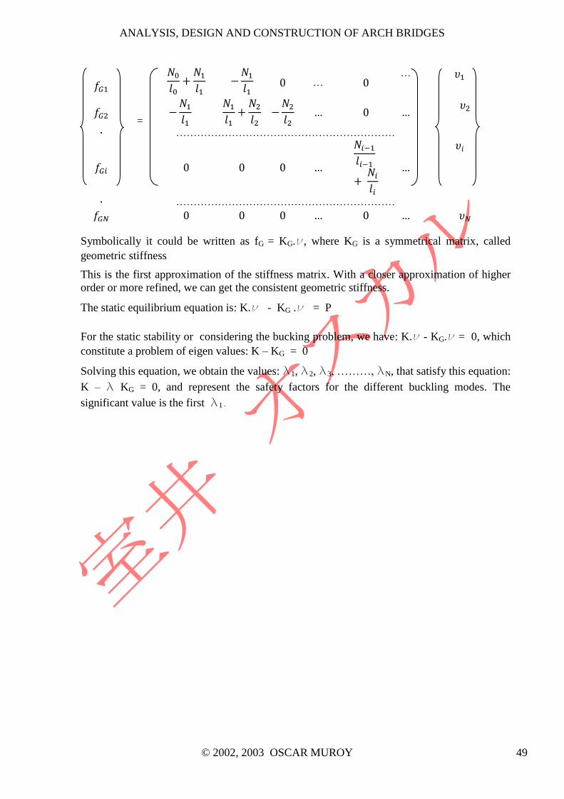
ANALYSIS, DESIGN AND CONSTRUCTION OF ARCH BRIDGES
© 2002, 2003 OSCAR MUROY 49
=
… …
………………………………………………………
………………………………………………………
Symbolically it could be written as fG = KG.ν, where KG is a symmetrical matrix, called
geometric stiffness
This is the first approximation of the stiffness matrix. With a closer approximation of higher
order or more refined, we can get the consistent geometric stiffness.
The static equilibrium equation is: K.ν - KG .ν = P
For the static stability or considering the bucking problem, we have: K.ν - KG.ν = 0, which
constitute a problem of eigen values: K – KG = 0
Solving this equation, we obtain the values: l1, l2, l3, ………, lN, that satisfy this equation:
K – l KG = 0, and represent the safety factors for the different buckling modes. The
significant value is the first l1.

ANALYSIS, DESIGN AND CONSTRUCTION OF ARCH BRIDGES
© 2002, 2003 OSCAR MUROY 50
10. EFFECTS OF TEMPERATURE VARIATION, SHRINKAGE SHORTENING AND
SUPPORT DISPLACEMENTS
Besides the actions of self-weight, dead loads and the traffic surcharges, we must study the
effects of temperature variation, in relation to temperature during construction; in the case of
concrete arches: shrinkage shortening and creep; and the support displacements due to soil
settlements.
a) With the temperature variation, we have a restrained expansion or shortening of the
structure, because the supports do not allow a free movement, causing, therefore, tension
or compression forces and bending moments in the arch.
Fig. 10.1
Then in an arch with a span l, between supports, for a temperature variation t, we would
have a free expansion of: l = .t.l, or in its orthogonal components:
lx = .t.lx
ly = .t.h
And the bending moment :
M = Ma – H.y – V.x
Being Ma, H and V, the bending moment, horizontal thrust and vertical reaction at the
springing. Ma and Mb are 0 for the two-hinged arch and the vertical reactions V are 0 for
arch supports at the same level.
b) For the shrinkage shortening in concrete arches, we have a restrained contraction, causing
therefore, traction forces in the arch.
Free contraction: l = sh.l, or in its orthogonal components
lx = sh.lx
ly = sh.h
And the bending moment:
M = Ma – H.y – V.x
c) In the case of support displacements, we would get the possible settlements:
x, y y
And the bending moment:
M = Ma – H.y – V.x

ANALYSIS, DESIGN AND CONSTRUCTION OF ARCH BRIDGES
© 2002, 2003 OSCAR MUROY 51
d) The creep or plastic flow of concrete, produces a gradual increase in the deflections of the
arch axis, without stress variation. The deflection at the end of the plastic flow is estimated
by the formulae
1
of
EE , being Eo, the initial modulus of Elasticity and Ef, the final
modulus of Elasticity. For a normal condition climate and the concrete preparation, =2.0.
Plastic flow will develop in a period of one to two years
Fig. 10.2 Built-in Arch
-140
-120
-100
-80
-60
-40
-20
0
20
40
60
80
100
0 5 10 15 20 25 30 35 40 45 50 55 60 65
Mz (T
.m
)
X (m)
BENDING MOMENTS DUE TO TEMP, DX and DY
Mz-temp
Mz-dx
Mz-dy
-16
-14
-12
-10
-8
-6
-4
-2
0
2
4
6
8
10
12
14
0 5 10 15 20 25 30 35 40 45 50 55 60 65
Fa (T
)
X (m)
AXIAL FORCES DUE TO TEMP, DX and DY
Fa-temp
Fa-dx
Fa-dy
-10
-8
-6
-4
-2
0
2
4
6
8
10
0 5 10 15 20 25 30 35 40 45 50 55 60 65
Fc (T
)
X (m)
SHEARING FORCES DUE TO TEMP, DX and DY
Fc-temp
Fc-dx
Fc-dy

ANALYSIS, DESIGN AND CONSTRUCTION OF ARCH BRIDGES
© 2002, 2003 OSCAR MUROY 52
Fig. 10.3 Two-hinged Arch
-2
-1.5
-1
-0.5
0
0.5
1
1.5
2
0 4.6 9.2 13.8 18.4 23 27.6 32.2 36.8 41.4 46 50.6 55.2 59.8 64.4 69 73.6 78.2 82.8 87.4 92
Fa (T
)
X (m)
AXIAL FORCES DUE TO TEMP, DX and DY
Fa-temp
Fa-dx
Fa-dy
-30
-25
-20
-15
-10
-5
0
5
10
15
20
25
30
0 4.6 9.2 13.8 18.4 23 27.6 32.2 36.8 41.4 46 50.6 55.2 59.8 64.4 69 73.6 78.2 82.8 87.4 92
Mz (T
.m
)
X (m)
BENDING MOMENTS DUE TO TEMP, DX and DY
Mz-temp
Mz-dx
Mz-dy
-1
-0.8
-0.6
-0.4
-0.2
0
0.2
0.4
0.6
0.8
1
0 4.6 9.2 13.8 18.4 23 27.6 32.2 36.8 41.4 46 50.6 55.2 59.8 64.4 69 73.6 78.2 82.8 87.4 92
Fc (T
)
X (m)
SHEARING FORCES DUE TO TEMP, DX and DY
Fc-temp
Fc-dx
Fc-dy

ANALYSIS, DESIGN AND CONSTRUCTION OF ARCH BRIDGES
© 2002, 2003 OSCAR MUROY 53
11. ARCH GEOMETRY CONTROL DURING CONSTRUCTION
As much as for the correct set-out of the arch geometry and to verify the structural behaviour
of the arch, it should be exercised strict control of the arch geometry all through the main
stages of the construction.
a-1) During the arch construction, immediately after pouring the concrete, when it is
constructed with complete false work or at every stage of arch construction, when it is
done by stages:
Fig. 11.1
yp = yc + vp
being :
yc, false work geometry of the arch.
vp, elastic deflection due to arch self-weight
yp, arch geometry, due to self-weight or deformed shape due to self-
weight
a-2) In the construction method by cantilevering-out, the cycle of operations that is repeated
shall be:
1. Cable tensioning to withstand the traveller weight in its new position.
2. Displacement of the traveller to its new position
3. Formwork, fixing the reinforcing bars, and pouring of concrete in its new position.
4. Cable tensioning, after the construction of the new stage.
5. Loosening of traveller to move to new position.
At stage i At stage i+1
Cable
Tensioning
Arch
Deflection
Cable
Tensioning
Arch
Deflection
Ti1 v
i1 T
i+11 v
i+11
Ti2 v
i2 T
i+12 v
i+12
Ti3 v
i3 T
i+13 v
i+13
.... .... .... ....
Tin-1 v
in-1 T
i+1n-1 v
i+1n-1
Ti+1
n vi+1
n

ANALYSIS, DESIGN AND CONSTRUCTION OF ARCH BRIDGES
© 2002, 2003 OSCAR MUROY 54
being :
vij, elastic deflection in the abscisa j, with the arch and the traveller
up to stage i
vi+1
j, elastic deflection in the abscisa j, with the arch and the traveller
up to stage i + 1
Tij, tension at the cable j, up to stage i
b) After the whole bridge construction:
Fig. 11.2
ym = yp + vm + i.vp
being :
vm, elastic deflection due to dead load
i , plastic flow coefficient due to self-weight, in this stage.
ym, arch geometry, with self-weight and dead load or deformed shape
due to self-weight and dead load.
c) After bridge construction and when concrete plastic flow has concluded:
ym, = yp + (1+).vm + .vp
being :
, final plastic flow coefficient (=2.0)
ym,, arch geometry, with self-weight, dead load after conclusion of
plastic flow
d) During load test or with surcharge:
Fig. 11.3
yf = ym, + vt
being :

ANALYSIS, DESIGN AND CONSTRUCTION OF ARCH BRIDGES
© 2002, 2003 OSCAR MUROY 55
vt, elastic deflection due to surcharge
yf, arch geometry, under test truck or surcharge load or deformed
shape under surcharge

ANALYSIS, DESIGN AND CONSTRUCTION OF ARCH BRIDGES
© 2002, 2003 OSCAR MUROY 56
12. BIBLIOGRAPHY
1) Theory of Structures, S. Timoshenko, Mc Graw Hill, 1945
2) Resistencia de Materiales, J. Courbon, Aguilar, 1968
3) Análisis de Estructuras Indeterminadas, J. S. Kinney, CECSA, 1963
4) Specifications of Highway Bridges, Japan Road Association, 1984
5) The Heads of the Valley Road, A. S. Coombs y L.W. Hinch, Proceedings of The
Institution of Civil Engineers, Oct. 1969
6) Concrete Bridges, A. C. Liebenberg, Longman Scientific and Technical, 1992
7) Theorie und Berechnung der Stahlbrücken, A. Hawranek y O. Steinhardt, Springer
Verlag, 1958
8) Estructuras de Hormigón Armado, Tomo VI, Bases para la construcción de puentes
monolíticos, F. Leonhardt, El Ateneo, 1992 (orig. 1979)
9) Theory of Elastic Stability, S. Timoshenko, Mc Graw Hill, 1961
10) Structural Steel Designer’s Handbook, R. Brockenbrough y F. Merritt, Mc Graw Hill,
1999
11) Bridges/Brücken, F. Leonhardt, Deutsche Verlags-Anstalt, 1994
12) Bridges in Japan, Dobuku Gakkai, several years