ECP 11-0514 ACB Commissioning...
16
Document Number: ECP 11-0514 Version: 2.0 Date: 23/05/2016 THIS IS AN UNCONTROLLED DOCUMENT, THE READER MUST CONFIRM ITS VALIDITY BEFORE USE ENGINEERING COMMISSIONING PROCEDURE ECP 11-0514 ACB COMMISSIONING PROCEDURE Network(s): EPN, LPN, SPN Summary: This document details the testing and commissioning procedures for air circuit- breakers and the associated reverse power relay where applicable. Author: Stephen Tucker Date: 23/05/2016 Approved By: Paul Williams Approved Date: 07/06/2016 This document forms part of the Company’s Integrated Business System and its requi rements are mandatory throughout UK Power Networks. Departure from these requirements may only be taken with the written approval of the Director of Asset Management. If you have any queries about this document please contact the author or owner of the current issue. Circulation UK Power Networks External All UK Power Networks G81 Website Asset Management Contractors Capital Programme ICPs/IDNOs Connections Meter Operators HSS&TT Network Operations UK Power Networks Services Other
Transcript of ECP 11-0514 ACB Commissioning...
Document Number: ECP 11-0514
Version: 2.0
Date: 23/05/2016
TH
IS IS
AN
UN
CO
NT
RO
LL
ED
DO
CU
ME
NT
, T
HE
RE
AD
ER
MU
ST
CO
NF
IRM
IT
S V
AL
IDIT
Y B
EF
OR
E U
SE
ENGINEERING COMMISSIONING PROCEDURE
ECP 11-0514
ACB COMMISSIONING PROCEDURE
Network(s): EPN, LPN, SPN
Summary: This document details the testing and commissioning procedures for air circuit-breakers and the associated reverse power relay where applicable.
Author: Stephen Tucker Date: 23/05/2016
Approved By: Paul Williams Approved Date: 07/06/2016
This document forms part of the Company’s Integrated Business System and its requirements are mandatory throughout UK Power Networks. Departure from these requirements may only be taken with the written approval of the Director of Asset Management. If you have any queries about this document please contact the author or owner of the current issue.
Circulation
UK Power Networks External
All UK Power Networks G81 Website
Asset Management Contractors
Capital Programme ICPs/IDNOs
Connections Meter Operators
HSS&TT
Network Operations
UK Power Networks Services
Other
ACB Commissioning Procedure Document Number: ECP 11-0514
Version: 2.0
Date: 23/05/2016
© UK Power Networks 2016 All rights reserved 2 of 16
Revision Record
Version 2.0 Review Date 07/06/2021
Date 23/05/2016 Author Stephen Tucker
Why has the document been updated: Periodic review.
What has changed:
Neutral-earth bonding requirements clarified (Section 16).
Asset data requirements updated (Section 20).
Shunt trip coil terminal designations added (ECP 11-0514a).
Schematic diagrams added (ECP 11-0514a).
Version 1.0 Review Date 23/06/2016
Date 23/06/2014 Author Stephen Tucker
New procedure for the commissioning of ACBs and reverse power relays based on legacy documents and good practice.
This document formalises the procedure for testing and commissioning existing and new ACBs to ensure a consistent approach to commissioning
ACB Commissioning Procedure Document Number: ECP 11-0514
Version: 2.0
Date: 23/05/2016
© UK Power Networks 2016 All rights reserved 3 of 16
Contents
1 Introduction ............................................................................................................. 4
2 Scope ....................................................................................................................... 4
3 References ............................................................................................................... 5
4 Abbreviations and Definitions ................................................................................ 5
5 Equipment ................................................................................................................ 5
6 Inspection ................................................................................................................ 6
7 Protection Settings .................................................................................................. 6
8 Functional Checks ................................................................................................... 6
9 Continuity Test ........................................................................................................ 7
10 High Voltage Insulation Test .................................................................................. 7
11 Secondary Injection Tests (using Full-function Test Kit) ..................................... 8
12 Trip Tests (if secondary injection is not possible) .............................................. 13
13 Reverse Power Relay (if fitted) ............................................................................. 14
14 Emergency Trip (if fitted) ...................................................................................... 14
15 SCADA Checks (if applicable) .............................................................................. 15
16 Metering Equipment (if fitted) ............................................................................... 15
17 Final Checks .......................................................................................................... 15
18 Test Equipment ..................................................................................................... 15
19 Certification ........................................................................................................... 15
20 Asset Data and Information .................................................................................. 15
20.1 UK Power Networks ................................................................................................ 15
20.2 Independent Connection Provider (ICP) .................................................................. 15
21 Dependent Documents.......................................................................................... 16
ACB Commissioning Procedure Document Number: ECP 11-0514
Version: 2.0
Date: 23/05/2016
© UK Power Networks 2016 All rights reserved 4 of 16
1 Introduction
1.1 This document details the testing and commissioning procedures for air circuit-breakers (ACB), and the associated reverse power relay (RPR) where applicable, that shall be satisfied before the ACB can be accepted as fit for service and energisation.
1.2 This procedure shall be carried out by the Commissioning Engineer or his appointed representative, who shall be an Authorised Person having appropriate training and/or experience.
1.3 This procedure shall be carried out in accordance with the requirements of the Distribution Safety Rules.
1.4 This procedure shall be carried out having regard to the requirements and recommendations of the manufacturer. If conflict exists between the requirements of the manufacturer and those of UK Power Networks the matter shall be referred to Asset Management (or your UK Power Networks nominated contact).
1.5 This procedure assumes:
The ACB is disconnected from the HV and LV networks.
The ACB is disconnected from the RTU (if fitted).
1.6 The results of all observations, tests, adjustments and all relevant remarks shall be recorded on the appropriate test form.
1.7 Where possible testing shall be carried without disconnecting or disturbing any wiring.
2 Scope
2.1 This procedure applies to all LV ACBs with overload and reverse power relay protection as detailed below:
Schneider Electric Masterpact NS1250, NT16H2, NW16H1 and NW20H1.
2.2 The associated test forms, which should be read in conjunction with this procedure, include specific schematic diagrams, connections and trip levels for the ACBs listed above.
2.3 This procedure is intended for use by UK Power Networks field staff, contractors and external connection providers.
ACB Commissioning Procedure Document Number: ECP 11-0514
Version: 2.0
Date: 23/05/2016
© UK Power Networks 2016 All rights reserved 5 of 16
3 References
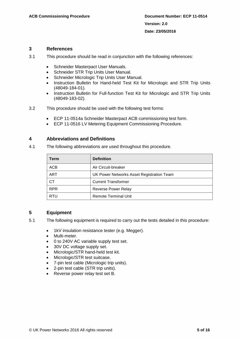
3.1 This procedure should be read in conjunction with the following references:
Schneider Masterpact User Manuals.
Schneider STR Trip Units User Manual.
Schneider Micrologic Trip Units User Manual.
Instruction Bulletin for Hand-held Test Kit for Micrologic and STR Trip Units (48049-184-01).
Instruction Bulletin for Full-function Test Kit for Micrologic and STR Trip Units (48049-183-02).
3.2 This procedure should be used with the following test forms:
ECP 11-0514a Schneider Masterpact ACB commissioning test form.
ECP 11-0516 LV Metering Equipment Commissioning Procedure.
4 Abbreviations and Definitions
4.1 The following abbreviations are used throughout this procedure.
Term Definition
ACB Air Circuit-breaker
ART UK Power Networks Asset Registration Team
CT Current Transformer
RPR Reverse Power Relay
RTU Remote Terminal Unit
5 Equipment
5.1 The following equipment is required to carry out the tests detailed in this procedure:
1kV insulation resistance tester (e.g. Megger).
Multi-meter.
0 to 240V AC variable supply test set.
30V DC voltage supply set.
Micrologic/STR hand-held test kit.
Micrologic/STR test suitcase.
7-pin test cable (Micrologic trip units).
2-pin test cable (STR trip units).
Reverse power relay test set B.
ACB Commissioning Procedure Document Number: ECP 11-0514
Version: 2.0
Date: 23/05/2016
© UK Power Networks 2016 All rights reserved 6 of 16
6 Inspection
6.1 Record the substation name, substation number, ACB model type, ACB serial number, Micrologic model type, protection settings and RPR details on the test form.
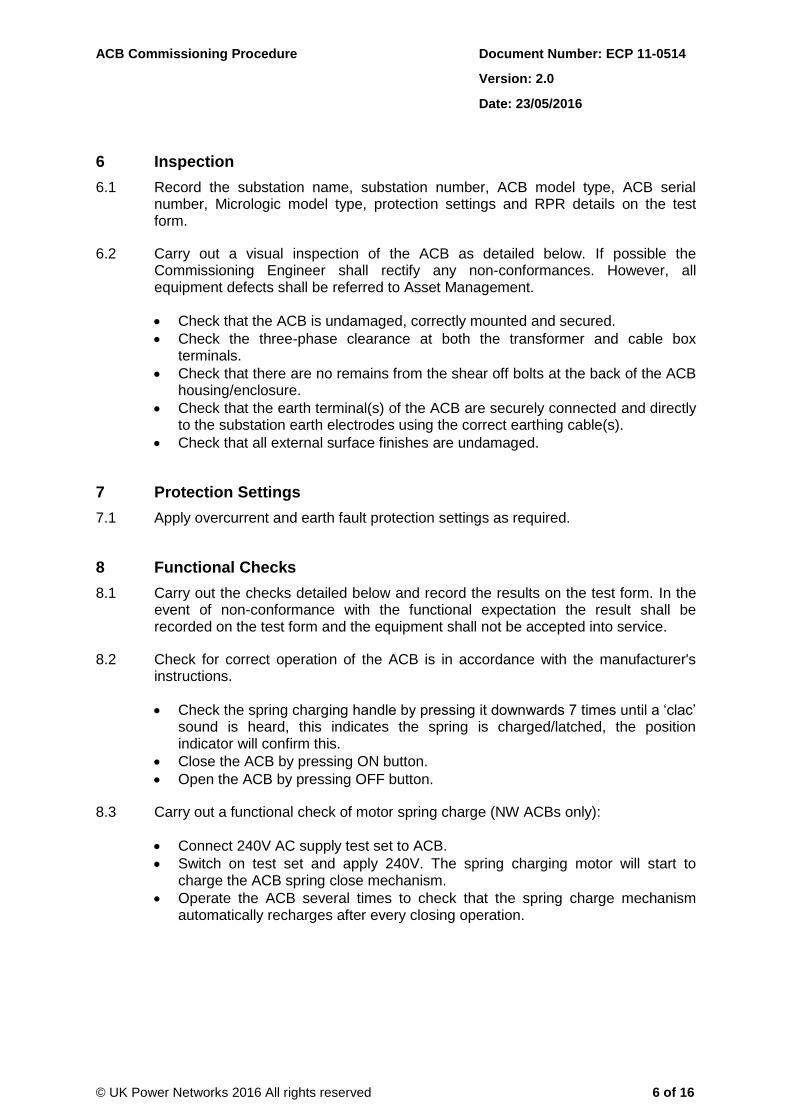
6.2 Carry out a visual inspection of the ACB as detailed below. If possible the Commissioning Engineer shall rectify any non-conformances. However, all equipment defects shall be referred to Asset Management.
Check that the ACB is undamaged, correctly mounted and secured.
Check the three-phase clearance at both the transformer and cable box terminals.
Check that there are no remains from the shear off bolts at the back of the ACB housing/enclosure.
Check that the earth terminal(s) of the ACB are securely connected and directly to the substation earth electrodes using the correct earthing cable(s).
Check that all external surface finishes are undamaged.
7 Protection Settings
7.1 Apply overcurrent and earth fault protection settings as required.
8 Functional Checks
8.1 Carry out the checks detailed below and record the results on the test form. In the event of non-conformance with the functional expectation the result shall be recorded on the test form and the equipment shall not be accepted into service.
8.2 Check for correct operation of the ACB is in accordance with the manufacturer's instructions.
Check the spring charging handle by pressing it downwards 7 times until a ‘clac’ sound is heard, this indicates the spring is charged/latched, the position indicator will confirm this.
Close the ACB by pressing ON button.
Open the ACB by pressing OFF button.
8.3 Carry out a functional check of motor spring charge (NW ACBs only):
Connect 240V AC supply test set to ACB.
Switch on test set and apply 240V. The spring charging motor will start to charge the ACB spring close mechanism.
Operate the ACB several times to check that the spring charge mechanism automatically recharges after every closing operation.
ACB Commissioning Procedure Document Number: ECP 11-0514
Version: 2.0
Date: 23/05/2016
© UK Power Networks 2016 All rights reserved 7 of 16
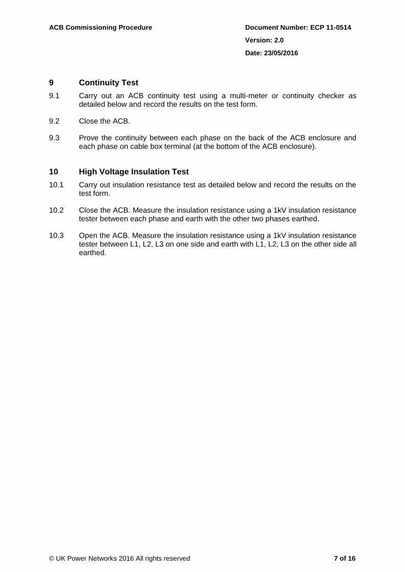
9 Continuity Test
9.1 Carry out an ACB continuity test using a multi-meter or continuity checker as detailed below and record the results on the test form.
9.2 Close the ACB.
9.3 Prove the continuity between each phase on the back of the ACB enclosure and each phase on cable box terminal (at the bottom of the ACB enclosure).
10 High Voltage Insulation Test
10.1 Carry out insulation resistance test as detailed below and record the results on the test form.
10.2 Close the ACB. Measure the insulation resistance using a 1kV insulation resistance tester between each phase and earth with the other two phases earthed.
10.3 Open the ACB. Measure the insulation resistance using a 1kV insulation resistance tester between L1, L2, L3 on one side and earth with L1, L2, L3 on the other side all earthed.

ACB Commissioning Procedure Document Number: ECP 11-0514
Version: 2.0
Date: 23/05/2016
© UK Power Networks 2016 All rights reserved 8 of 16
11 Secondary Injection Tests (using Full-function Test Kit)
11.1 Carry out the secondary injection tests below using the Schneider full-function (suitcase) test kit (refer to Schneider instruction bulletin 48049-183-02 for further details) and record the results on the test form.
11.2 Close the ACB.
11.3 Assemble the test kit as follows:
Connect the test lead to test kit and to 10-pin test socket on the trip unit.
Connect the power cable to full-function test kit.
Turn on the test kit and observe the power on test.
If Spinning Schneider Electric logo resolves to the title screen, proceed with use, if it continues to spin after 10 seconds and the title screen does not appear, abort the test and return the test kit for repair.
11.4 Press Next on the touch screen.
ACB Commissioning Procedure Document Number: ECP 11-0514
Version: 2.0
Date: 23/05/2016
© UK Power Networks 2016 All rights reserved 9 of 16
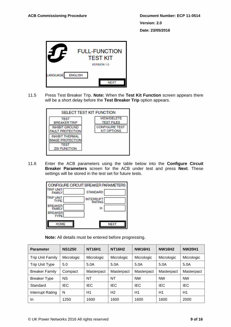
11.5 Press Test Breaker Trip. Note: When the Test Kit Function screen appears there will be a short delay before the Test Breaker Trip option appears.
11.6 Enter the ACB parameters using the table below into the Configure Circuit Breaker Parameters screen for the ACB under test and press Next. These settings will be stored in the test set for future tests.
Note: All details must be entered before progressing.
Parameter NS1250 NT16H1 NT16H2 NW16H1 NW16H2 NW20H1
Trip Unit Family Micrologic Micrologic Micrologic Micrologic Micrologic Micrologic
Trip Unit Type 5.0 5.0A 5.0A 5.0A 5.0A 5.0A
Breaker Family Compact Masterpact Masterpact Masterpact Masterpact Masterpact
Breaker Type NS NT NT NW NW NW
Standard IEC IEC IEC IEC IEC IEC
Interrupt Rating N H1 H2 H1 H1 H1
In 1250 1600 1600 1600 1600 2000
ACB Commissioning Procedure Document Number: ECP 11-0514
Version: 2.0
Date: 23/05/2016
© UK Power Networks 2016 All rights reserved 10 of 16
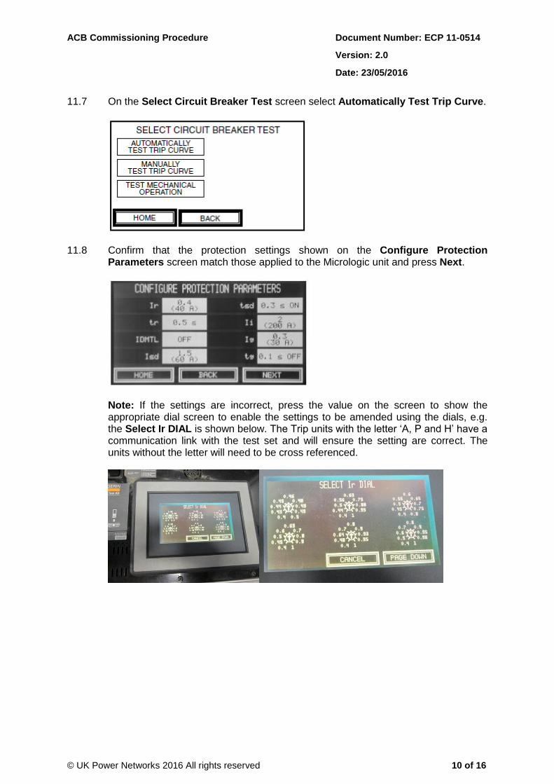
11.7 On the Select Circuit Breaker Test screen select Automatically Test Trip Curve.
11.8 Confirm that the protection settings shown on the Configure Protection Parameters screen match those applied to the Micrologic unit and press Next.
Note: If the settings are incorrect, press the value on the screen to show the appropriate dial screen to enable the settings to be amended using the dials, e.g. the Select Ir DIAL is shown below. The Trip units with the letter ‘A, P and H’ have a communication link with the test set and will ensure the setting are correct. The units without the letter will need to be cross referenced.
ACB Commissioning Procedure Document Number: ECP 11-0514
Version: 2.0
Date: 23/05/2016
© UK Power Networks 2016 All rights reserved 11 of 16
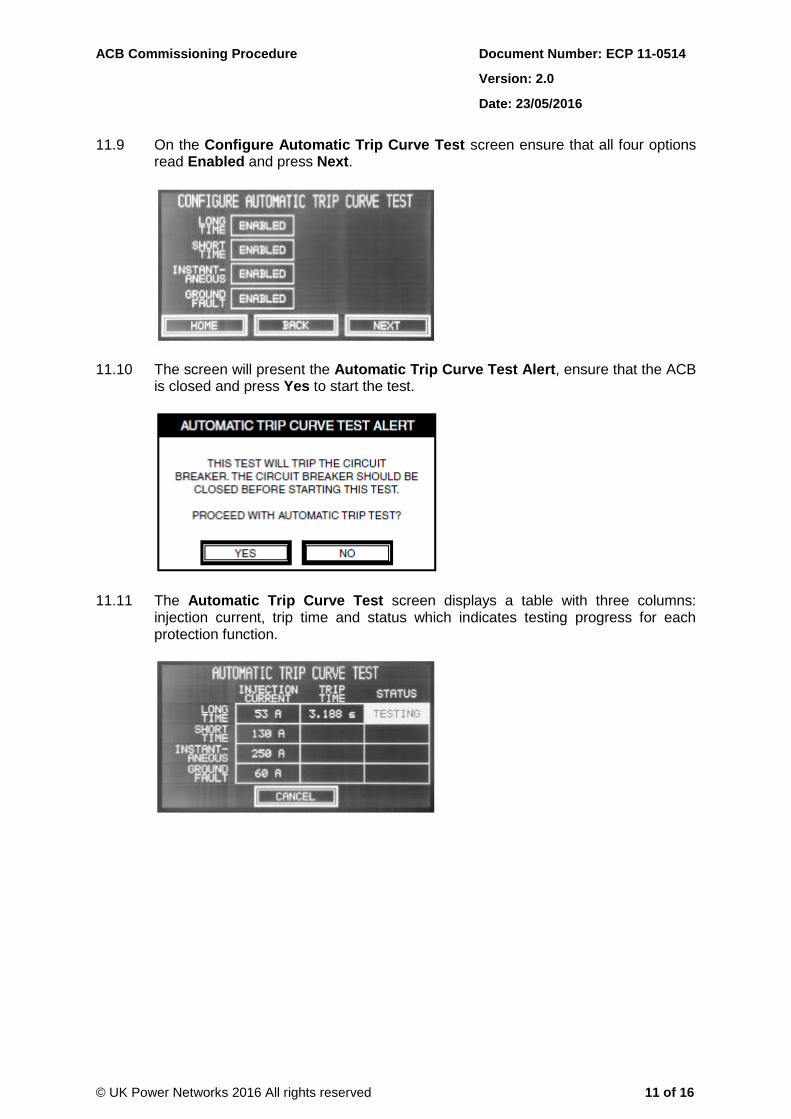
11.9 On the Configure Automatic Trip Curve Test screen ensure that all four options read Enabled and press Next.
11.10 The screen will present the Automatic Trip Curve Test Alert, ensure that the ACB is closed and press Yes to start the test.
11.11 The Automatic Trip Curve Test screen displays a table with three columns: injection current, trip time and status which indicates testing progress for each protection function.
ACB Commissioning Procedure Document Number: ECP 11-0514
Version: 2.0
Date: 23/05/2016
© UK Power Networks 2016 All rights reserved 12 of 16
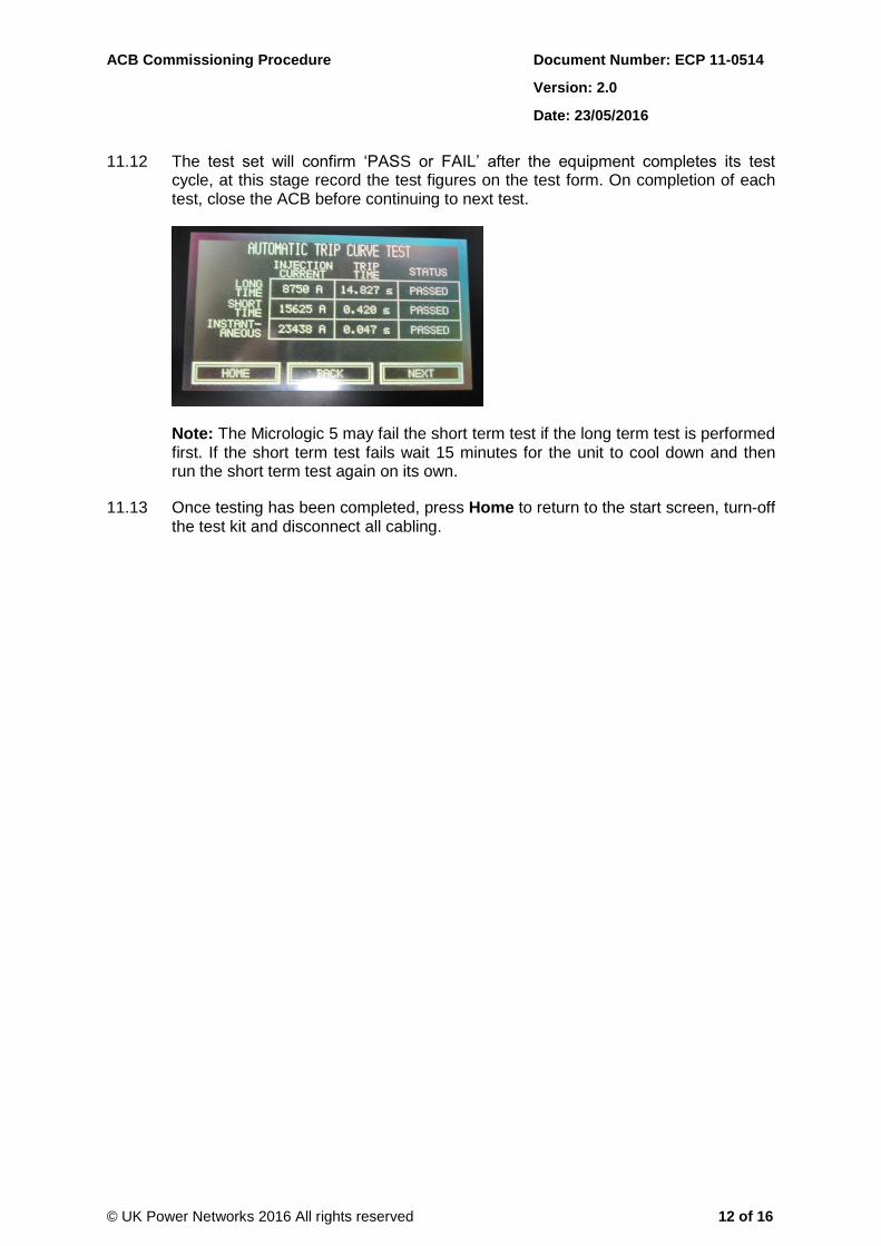
11.12 The test set will confirm ‘PASS or FAIL’ after the equipment completes its test cycle, at this stage record the test figures on the test form. On completion of each test, close the ACB before continuing to next test.
Note: The Micrologic 5 may fail the short term test if the long term test is performed first. If the short term test fails wait 15 minutes for the unit to cool down and then run the short term test again on its own.
11.13 Once testing has been completed, press Home to return to the start screen, turn-off the test kit and disconnect all cabling.
ACB Commissioning Procedure Document Number: ECP 11-0514
Version: 2.0
Date: 23/05/2016
© UK Power Networks 2016 All rights reserved 13 of 16
12 Trip Tests (if secondary injection is not possible)
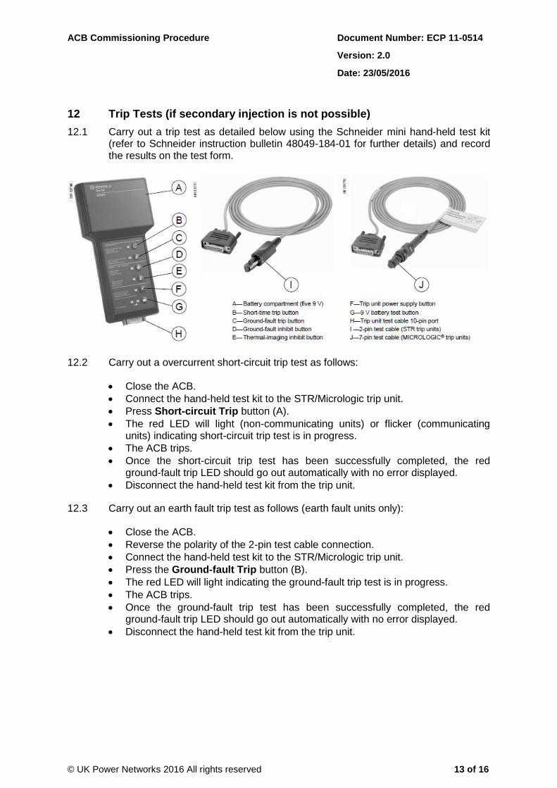
12.1 Carry out a trip test as detailed below using the Schneider mini hand-held test kit (refer to Schneider instruction bulletin 48049-184-01 for further details) and record the results on the test form.
12.2 Carry out a overcurrent short-circuit trip test as follows:
Close the ACB.
Connect the hand-held test kit to the STR/Micrologic trip unit.
Press Short-circuit Trip button (A).
The red LED will light (non-communicating units) or flicker (communicating units) indicating short-circuit trip test is in progress.
The ACB trips.
Once the short-circuit trip test has been successfully completed, the red ground-fault trip LED should go out automatically with no error displayed.
Disconnect the hand-held test kit from the trip unit.
12.3 Carry out an earth fault trip test as follows (earth fault units only):
Close the ACB.
Reverse the polarity of the 2-pin test cable connection.
Connect the hand-held test kit to the STR/Micrologic trip unit.
Press the Ground-fault Trip button (B).
The red LED will light indicating the ground-fault trip test is in progress.
The ACB trips.
Once the ground-fault trip test has been successfully completed, the red ground-fault trip LED should go out automatically with no error displayed.
Disconnect the hand-held test kit from the trip unit.
ACB Commissioning Procedure Document Number: ECP 11-0514
Version: 2.0
Date: 23/05/2016
© UK Power Networks 2016 All rights reserved 14 of 16
13 Reverse Power Relay (if fitted)
13.1 Commission the reverse power relay (RPR) using Test Set B following the steps below.
13.2 Before testing check the transformer links are open and the HV circuit-breaker and ACB are closed.
13.3 Connect the test set.
13.4 Check the non-operation of overcurrent relays at 8A.
All overcurrent relay contacts remain open.
13.5 Check the operation of overcurrent relays at 10A:
All overcurrent relay contacts close in turn.
13.6 Check non-operation of directional relay at 10A, 25V:
Induction cup on the directional relay does not move. Note any movement of the induction cup in the comment section of the test form.
Directional relay contacts remain open.
13.7 Check operation of directional relay and auxiliary tripping relay at 10A, 50V:
Directional relay contacts close via the induction cup.
Auxiliary trip relay flag operates and red light on the test set illuminate.
13.8 Check ‘drop off” of overcurrent relays at 5A:
All overcurrent relay contacts open.
13.9 Check RPR trip operation.
13.10 Check RPR intertrip operation.
14 Emergency Trip (if fitted)
14.1 Check that the correct voltage has been used on the shunt trip coil.
14.2 Check that the emergency trip button correctly trips the ACB.
ACB Commissioning Procedure Document Number: ECP 11-0514
Version: 2.0
Date: 23/05/2016
© UK Power Networks 2016 All rights reserved 15 of 16
15 SCADA Checks (if applicable)
15.1 Check for the correct operation of the remote control:
Reconnect umbilical cable to RTU (if fitted).
Simulate or carry out a remote open.
Simulate or carry out a remote close.
16 Metering Equipment (if fitted)
16.1 Commission the metering CTs in accordance with ECP 11-0516.
17 Final Checks
17.1 On completion of the commissioning tests check the following:
A neutral-earth bond is installed between transformer neutral bushing and transformer tank earth terminal where the ACB is mounted directly on the transformer. Note: This configuration cannot be used at a site with separate HV and LV earths.
All links are replaced and secure.
Spring is charged.
18 Test Equipment
18.1 Record the purpose, make, type and serial or asset number of all test equipment used during commissioning on the test form.
19 Certification
19.1 When all the tests have been satisfactorily completed, sign and date the test form. The test form should be left on-site in a plastic wallet and in a secure location.
20 Asset Data and Information
20.1 UK Power Networks
20.1.1 Send a copy of the completed test form and the asset data form to the Asset Registration Team (ART) via the appropriate mailbox below.
20.2 Independent Connection Provider (ICP)
20.2.1 Send a copy of the completed test form and the asset data form to the Competition-in-Connections Delivery Project Manager.
ACB Commissioning Procedure Document Number: ECP 11-0514
Version: 2.0
Date: 23/05/2016
© UK Power Networks 2016 All rights reserved 16 of 16
21 Dependent Documents
21.1 This document is referenced in the following documents, any of which may be affected by updates.
ECS 03-0037 Non Standard Installation of LV Cables to ACBs on the LPN Network
ECS 03-0054 Connection of LV Large Services to Secondary Distribution Substations
ECP 11-0501 Secondary Commissioning Procedures
ECP 11-0511 Ground Mounted Switchgear Commissioning Procedure
ECP 11-0512 Ground Mounted Switchgear with Relays Commissioning Procedure