
ECP 11-0512e Schneider CE6 with Sepam 1000+...
26
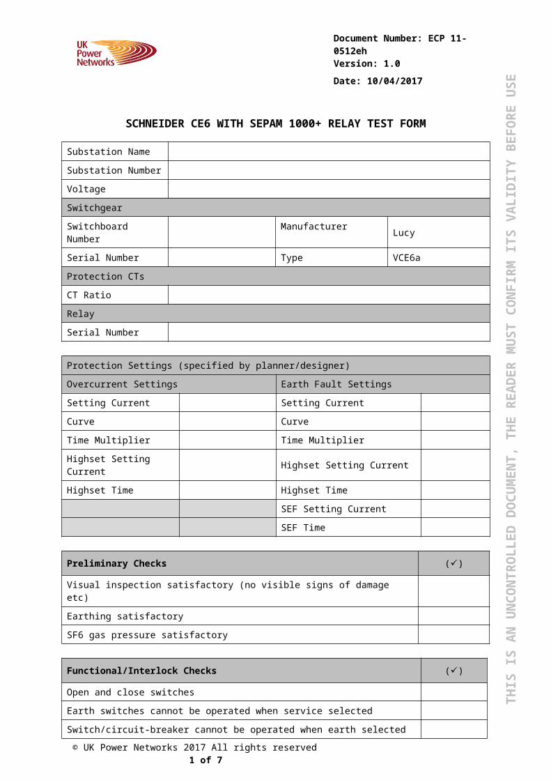
THIS IS AN UNCONTROLLED DOCUMENT, THE READER MUST CONFIRM ITS VALIDITY BEFORE USE Document Number: ECP 11- 0512eh Version: 1.0 Date: 10/04/2017 SCHNEIDER CE6 WITH SEPAM 1000+ RELAY TEST FORM Substation Name Substation Number Voltage Switchgear Switchboard Number Manufacturer Lucy Serial Number Type VCE6a Protection CTs CT Ratio Relay Serial Number Protection Settings (specified by planner/designer) Overcurrent Settings Earth Fault Settings Setting Current Setting Current Curve Curve Time Multiplier Time Multiplier Highset Setting Current Highset Setting Current Highset Time Highset Time SEF Setting Current SEF Time Preliminary Checks () Visual inspection satisfactory (no visible signs of damage etc) Earthing satisfactory SF6 gas pressure satisfactory Functional/Interlock Checks () Open and close switches Earth switches cannot be operated when service selected Switch/circuit-breaker cannot be operated when earth selected © UK Power Networks 2017 All rights reserved 1 of 7
Transcript of ECP 11-0512e Schneider CE6 with Sepam 1000+...
THIS
IS A
N U
NC
ON
TRO
LLED
DO
CU
MEN
T, T
HE
REA
DER
MU
ST C
ON
FIR
M IT
S VA
LID
ITY
BEF
OR
E U
SE
Document Number: ECP 11-0512h
Version: 1.0
Date: 10/04/2017
LUCY VCE6A WITH ARGUS 7SR11 RELAY TEST FORM
Substation Name
Substation Number
Voltage
Switchgear
Switchboard Number Manufacturer Lucy
Serial Number Type VCE6a
Protection CTs
CT Ratio
Relay
Serial Number
Protection Settings (specified by planner/designer)
Overcurrent Settings Earth Fault Settings
Setting Current Setting Current
Curve Curve
Time Multiplier Time Multiplier
Highset Setting Current Highset Setting Current
Highset Time Highset Time
SEF Setting Current
SEF Time
Preliminary Checks ()
Visual inspection satisfactory (no visible signs of damage etc)
Earthing satisfactory
SF6 gas pressure satisfactory
Functional/Interlock Checks ()
Open and close switches
Earth switches cannot be operated when service selected
Switch/circuit-breaker cannot be operated when earth selected
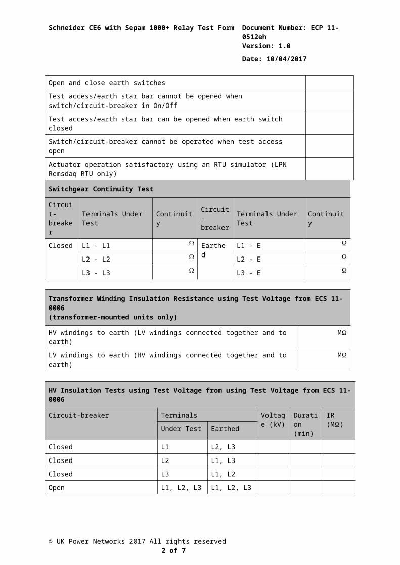
Open and close earth switches
Test access/earth star bar cannot be opened when switch/circuit-breaker in On/Off
Test access/earth star bar can be opened when earth switch closed
Switch/circuit-breaker cannot be operated when test access open
Actuator operation satisfactory using an RTU simulator (LPN Remsdaq RTU only)
© UK Power Networks 2017 All rights reserved 1 of 7
Schneider CE6 with Sepam 1000+ Relay Test Form Document Number: ECP 11-0512h
Version: 1.0
Date: 10/04/2017
Switchgear Continuity Test
Circuit-breaker Terminals Under Test Continuity Circuit-
breakerTerminals Under Test Continuity
Closed L1 - L1 Earthed L1 - E
L2 - L2 L2 - E
L3 - L3 L3 - E
Transformer Winding Insulation Resistance using Test Voltage from ECS 11-0006(transformer-mounted units only)
HV windings to earth (LV windings connected together and to earth) M
LV windings to earth (HV windings connected together and to earth) M
HV Insulation Tests using Test Voltage from using Test Voltage from ECS 11-0006
Circuit-breaker Terminals Voltage (kV)
Duration (min)
IR (M)
Under Test Earthed
Closed L1 L2, L3
Closed L2 L1, L3
Closed L3 L1, L2
Open L1, L2, L3 L1, L2, L3
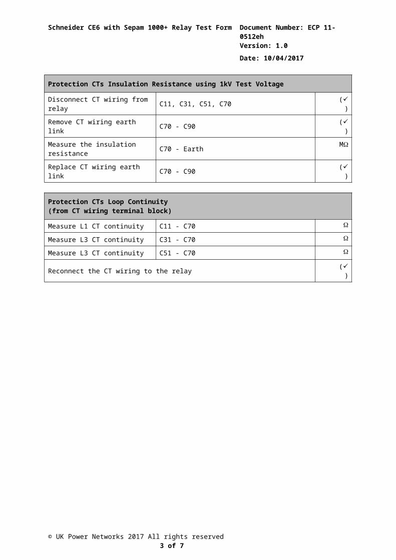
Protection CTs Insulation Resistance using 1kV Test Voltage
Disconnect CT wiring from relay C11, C31, C51, C70 ()
Remove CT wiring earth link C70 - C90 ()
Measure the insulation resistance C70 - Earth M
Replace CT wiring earth link C70 - C90 ()
Protection CTs Loop Continuity(from CT wiring terminal block)
Measure L1 CT continuity C11 - C70
Measure L3 CT continuity C31 - C70
Measure L3 CT continuity C51 - C70
Reconnect the CT wiring to the relay ()
© UK Power Networks 2017 All rights reserved 2 of 7
Schneider CE6 with Sepam 1000+ Relay Test Form Document Number: ECP 11-0512h
Version: 1.0
Date: 10/04/2017
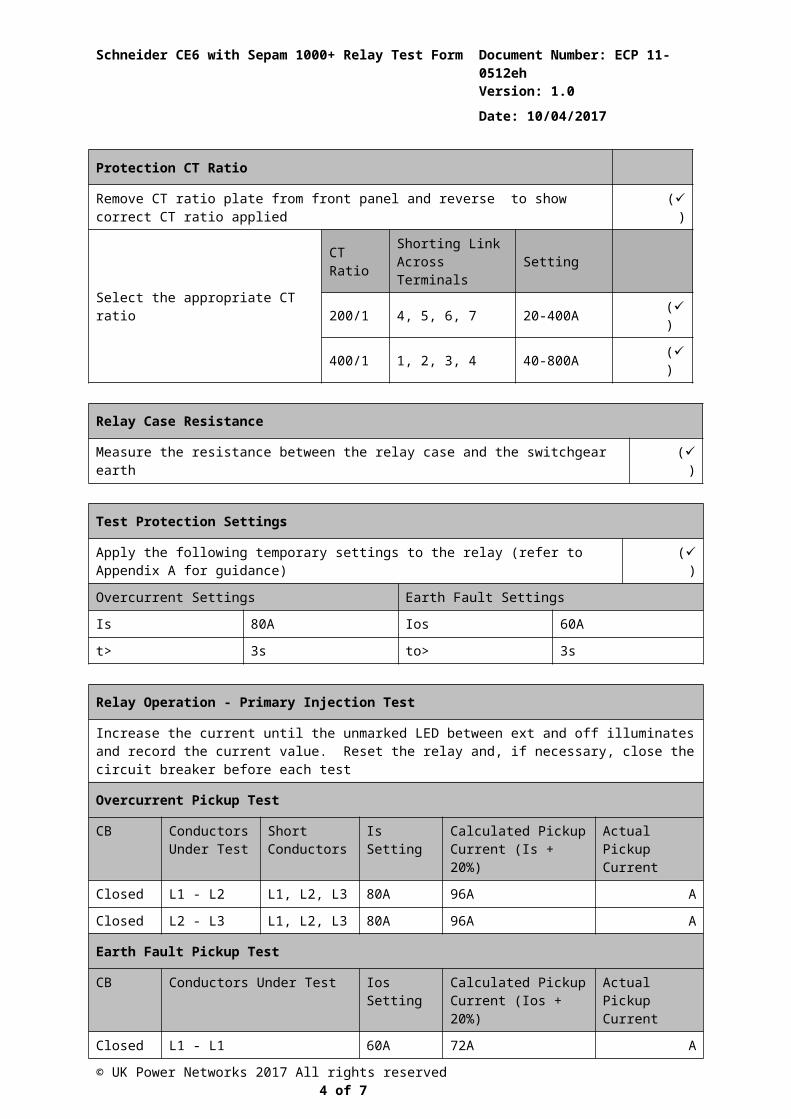
Protection CT Ratio
Remove CT ratio plate from front panel and reverse to show correct CT ratio applied ()
Select the appropriate CT ratio
CT Ratio Shorting Link Across Terminals Setting
200/1 4, 5, 6, 7 20-400A ()
400/1 1, 2, 3, 4 40-800A ()
Relay Case Resistance
Measure the resistance between the relay case and the switchgear earth ()
Test Protection Settings
Apply the following temporary settings to the relay (refer to Appendix A for guidance) ()
Overcurrent Settings Earth Fault Settings
Is 80A Ios 60A
t> 3s to> 3s
Relay Operation - Primary Injection Test
Increase the current until the unmarked LED between ext and off illuminates and record the current value. Reset the relay and, if necessary, close the circuit breaker before each test
Overcurrent Pickup Test
CB Conductors Under Test
Short Conductors
Is Setting Calculated Pickup Current (Is + 20%)
Actual Pickup Current
Closed L1 - L2 L1, L2, L3 80A 96A A
Closed L2 - L3 L1, L2, L3 80A 96A A
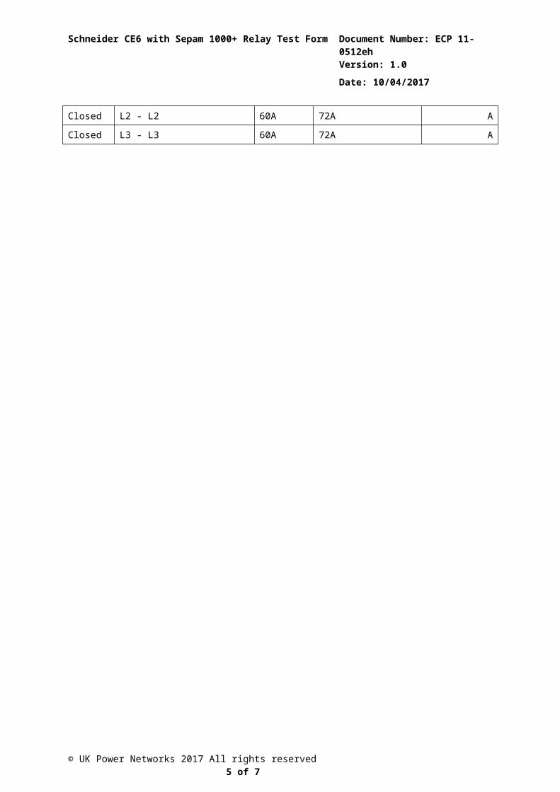
Earth Fault Pickup Test
CB Conductors Under Test Ios Setting Calculated Pickup Current (Ios + 20%)
Actual Pickup Current
Closed L1 - L1 60A 72A A
Closed L2 - L2 60A 72A A
Closed L3 - L3 60A 72A A
© UK Power Networks 2017 All rights reserved 3 of 7
Schneider CE6 with Sepam 1000+ Relay Test Form Document Number: ECP 11-0512h
Version: 1.0
Date: 10/04/2017
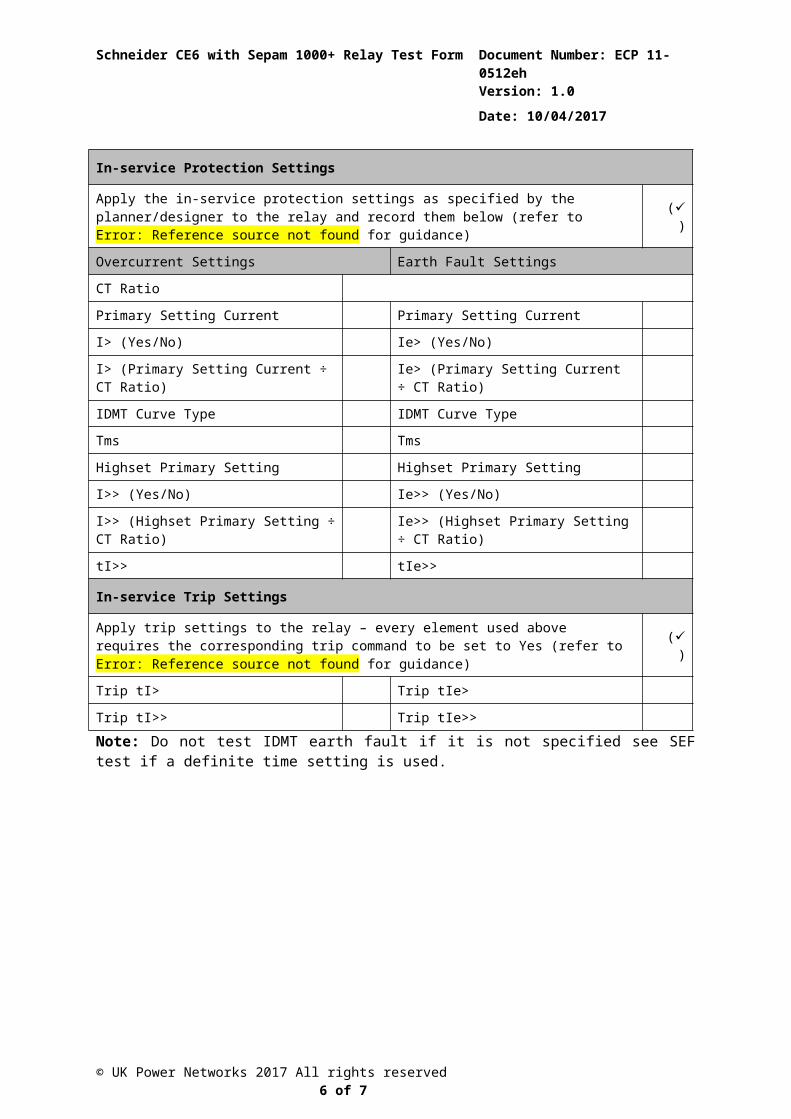
In-service Protection Settings
Apply the in-service protection settings as specified by the planner/designer to the relay and record them below (refer to Error: Reference source not found for guidance) ()
Overcurrent Settings Earth Fault Settings
CT Ratio
Primary Setting Current Primary Setting Current
I> (Yes/No) Ie> (Yes/No)
I> (Primary Setting Current ÷ CT Ratio) Ie> (Primary Setting Current ÷ CT Ratio)
IDMT Curve Type IDMT Curve Type
Tms Tms
Highset Primary Setting Highset Primary Setting
I>> (Yes/No) Ie>> (Yes/No)
I>> (Highset Primary Setting ÷ CT Ratio) Ie>> (Highset Primary Setting ÷ CT Ratio)
tI>> tIe>>
In-service Trip Settings
Apply trip settings to the relay – every element used above requires the corresponding trip command to be set to Yes (refer to Error: Reference source not found for guidance) ()
Trip tI> Trip tIe>
Trip tI>> Trip tIe>>Note: Do not test IDMT earth fault if it is not specified see SEF test if a definite time setting is used.
© UK Power Networks 2017 All rights reserved 4 of 7
Schneider CE6 with Sepam 1000+ Relay Test Form Document Number: ECP 11-0512h
Version: 1.0
Date: 10/04/2017
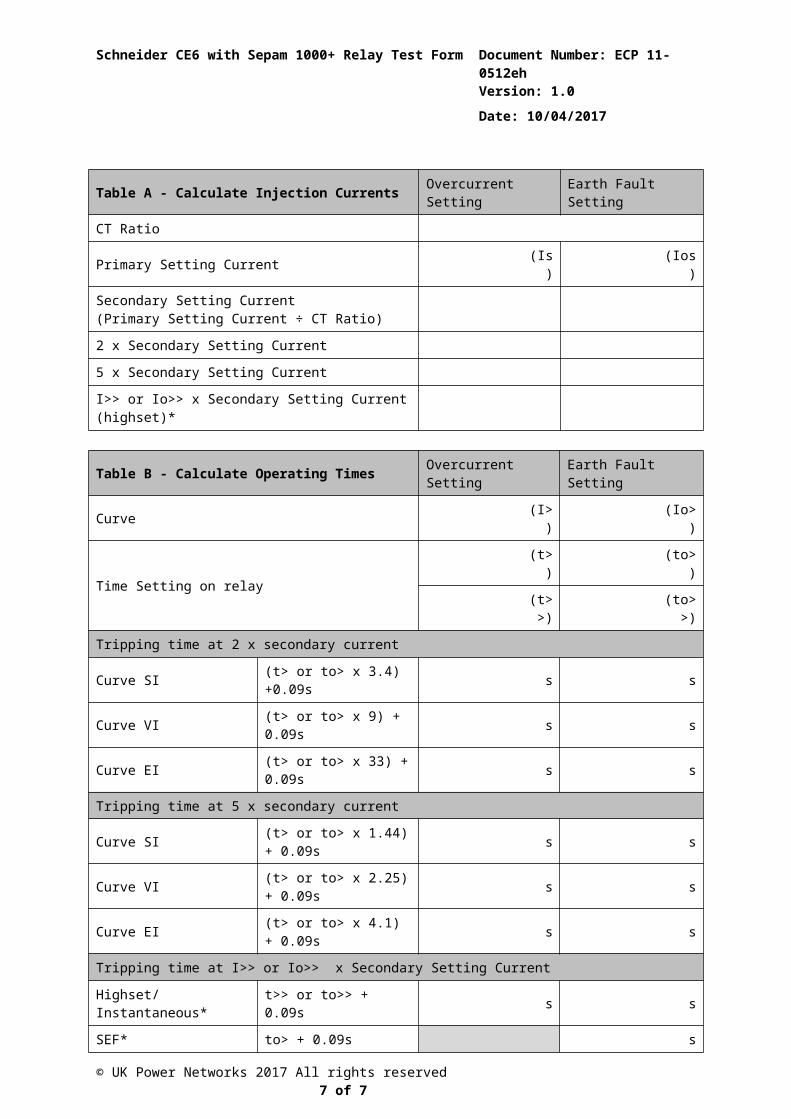
Table A - Calculate Injection Currents Overcurrent Setting Earth Fault Setting
CT Ratio
Primary Setting Current (Is) (Ios)
Secondary Setting Current (Primary Setting Current ÷ CT Ratio)
2 x Secondary Setting Current
5 x Secondary Setting Current
I>> or Io>> x Secondary Setting Current (highset)*
Table B - Calculate Operating Times Overcurrent Setting Earth Fault Setting
Curve (I>) (Io>)
Time Setting on relay(t>) (to>)
(t>>) (to>>)
Tripping time at 2 x secondary current
Curve SI (t> or to> x 3.4) +0.09s s s
Curve VI (t> or to> x 9) + 0.09s s s
Curve EI (t> or to> x 33) + 0.09s s s
Tripping time at 5 x secondary current
Curve SI (t> or to> x 1.44) + 0.09s s s
Curve VI (t> or to> x 2.25) + 0.09s s s
Curve EI (t> or to> x 4.1) + 0.09s s s
Tripping time at I>> or Io>> x Secondary Setting Current
Highset/Instantaneous* t>> or to>> + 0.09s s s
SEF* to> + 0.09s s
* Only calculate highset, instantaneous or SEF settings if used.
© UK Power Networks 2017 All rights reserved 5 of 7
Schneider CE6 with Sepam 1000+ Relay Test Form Document Number: ECP 11-0512h
Version: 1.0
Date: 10/04/2017
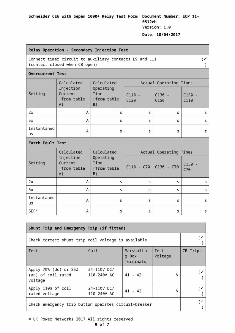
Relay Operation - Secondary Injection Test
Connect timer circuit to auxiliary contacts L9 and L11 (contact closed when CB open) ()
Overcurrent Test
SettingCalculated Injection Current(from table A)
Calculated Operating Time (from table B)
Actual Operating Times
C110 – C130 C130 – C150 C150 - C110
2x A s s s s
5x A s s s s
Instantaneous A s s s s
Earth Fault Test
SettingCalculated Injection Current(from table A)
Calculated Operating Time (from table B)
Actual Operating Times
C110 - C70 C130 - C70 C150 - C70
2x A s s s s
5x A s s s s
Instantaneous A s s s s
SEF* A s s s s
Shunt Trip and Emergency Trip (if fitted)
Check correct shunt trip coil voltage is available ()
Test Coil Marshalling Box Terminals
Test Voltage CB Trips
Apply 70% (dc) or 85% (ac) of coil rated voltage
24-110V DC/110-240V AC 41 - 42 V ()
Apply 110% of coil rated voltage
24-110V DC/110-240V AC 41 - 42 V ()
Check emergency trip button operates circuit-breaker ()
© UK Power Networks 2017 All rights reserved 6 of 7
Schneider CE6 with Sepam 1000+ Relay Test Form Document Number: ECP 11-0512h
Version: 1.0
Date: 10/04/2017
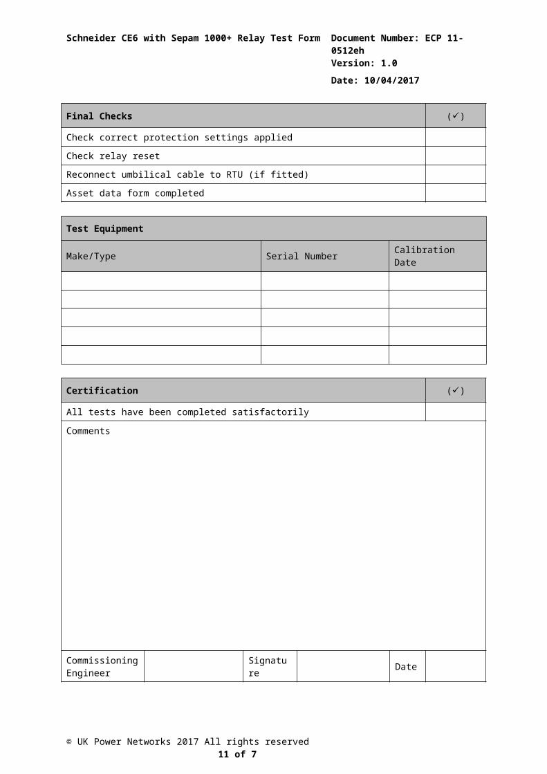
Final Checks ()
Check correct protection settings applied
Check relay reset
Reconnect umbilical cable to RTU (if fitted)
Asset data form completed
Test Equipment
Make/Type Serial Number Calibration Date
Certification ()
All tests have been completed satisfactorily
Comments
Commissioning Engineer Signature Date
The completed test form shall be left on-site in a plastic wallet and in secure location. A copy of the completed test shall be sent to the relevant ART mailbox.
© UK Power Networks 2017 All rights reserved 7 of 7
Schneider CE6 with Sepam 1000+ Relay Test Form Document Number: ECP 11-0512h
Version: 1.0
Date: 10/04/2017
Appendix A Argus 7SR11
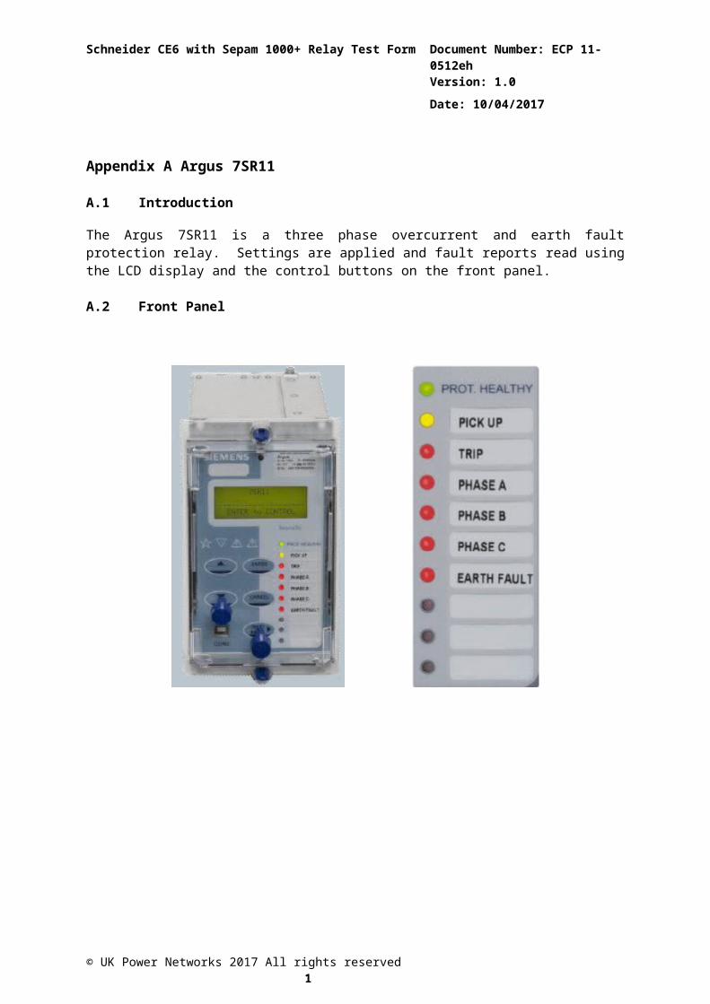
A.1 Introduction
The Argus 7SR11 is a three phase overcurrent and earth fault protection relay. Settings are applied and fault reports read using the LCD display and the control buttons on the front panel.
A.2 Front Panel
© UK Power Networks 2017 All rights reserved 1
Schneider CE6 with Sepam 1000+ Relay Test Form Document Number: ECP 11-0512h
Version: 1.0
Date: 10/04/2017
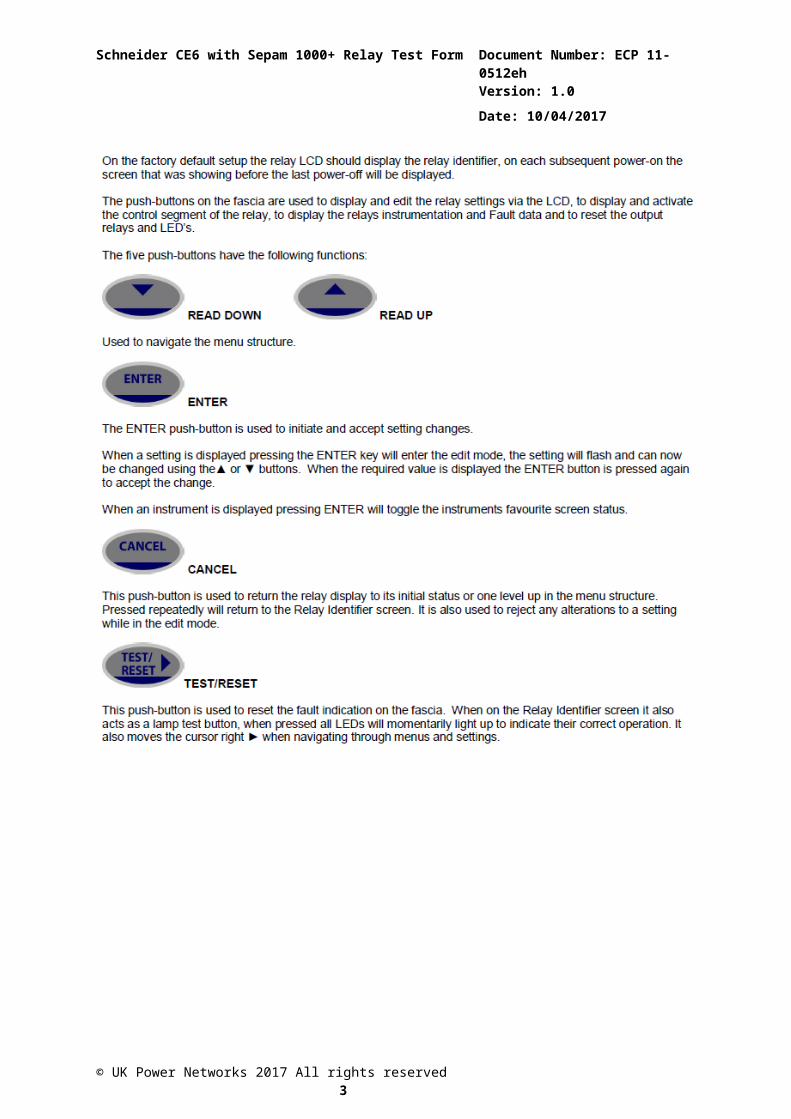
A.3 Relay Front Panel Navigation
The basic menu structure flow diagram is shown in A.66 after the following relay front button description. This diagram shows the main modes of Display, Settings Mode, Instrument Mode, Fault Data Mode and Control Mode. Relay programming procedure is described in A.4
When the relay leaves the factory all data storage areas are cleared and the settings set to default as specified in the settings document.
When the relay is first energised the user is presented with the screen description as shown in A.2
© UK Power Networks 2017 All rights reserved 2
Schneider CE6 with Sepam 1000+ Relay Test Form Document Number: ECP 11-0512h
Version: 1.0
Date: 10/04/2017
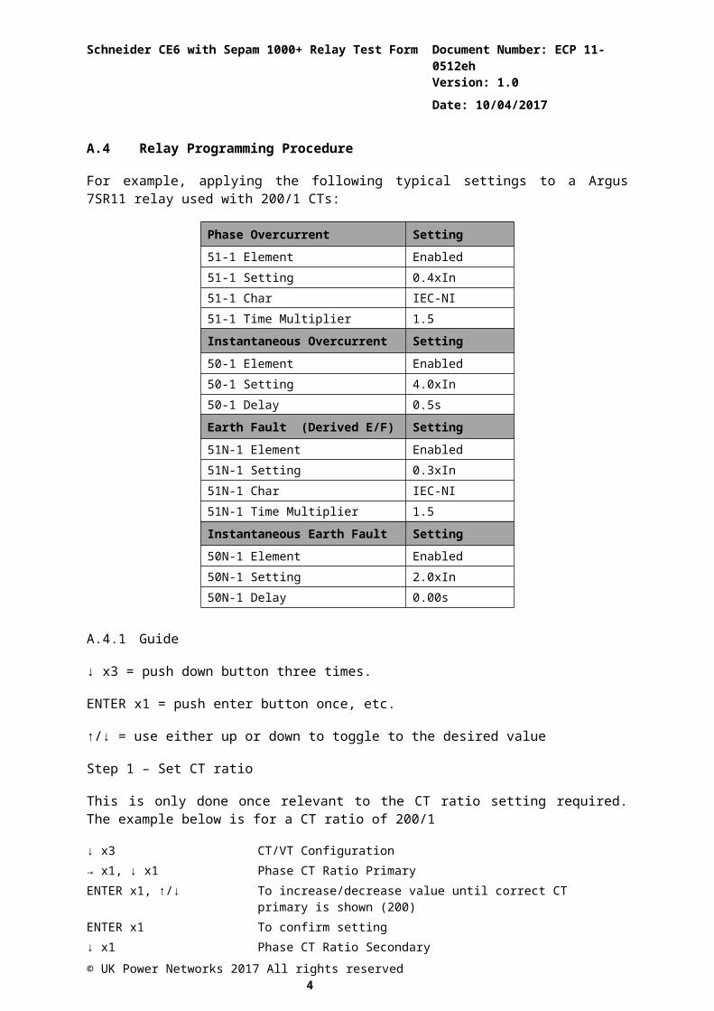
A.4 Relay Programming Procedure
For example, applying the following typical settings to a Argus 7SR11 relay used with 200/1 CTs:
Phase Overcurrent Setting51-1 Element Enabled51-1 Setting 0.4xIn51-1 Char IEC-NI51-1 Time Multiplier 1.5
Instantaneous Overcurrent Setting50-1 Element Enabled50-1 Setting 4.0xIn50-1 Delay 0.5s
Earth Fault (Derived E/F) Setting51N-1 Element Enabled51N-1 Setting 0.3xIn51N-1 Char IEC-NI51N-1 Time Multiplier 1.5
Instantaneous Earth Fault Setting50N-1 Element Enabled50N-1 Setting 2.0xIn50N-1 Delay 0.00s
A.4.1 Guide
↓ x3 = push down button three times.
ENTER x1 = push enter button once, etc.
↑/↓ = use either up or down to toggle to the desired value
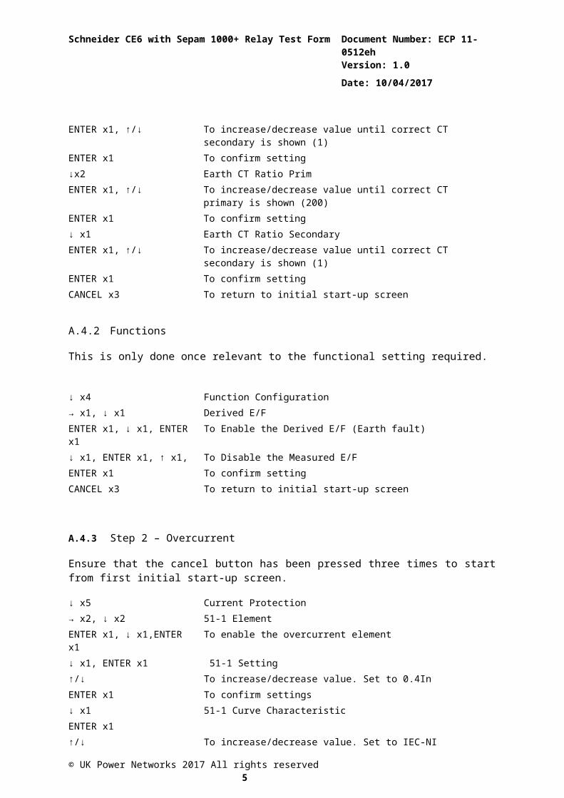
Step 1 – Set CT ratio
This is only done once relevant to the CT ratio setting required. The example below is for a CT ratio of 200/1
↓ x3 CT/VT Configuration→ x1, ↓ x1 Phase CT Ratio PrimaryENTER x1, ↑/↓ To increase/decrease value until correct CT primary is shown (200)ENTER x1 To confirm setting↓ x1 Phase CT Ratio SecondaryENTER x1, ↑/↓ To increase/decrease value until correct CT secondary is shown (1)ENTER x1 To confirm setting↓x2 Earth CT Ratio PrimENTER x1, ↑/↓ To increase/decrease value until correct CT primary is shown (200)ENTER x1 To confirm setting↓ x1 Earth CT Ratio SecondaryENTER x1, ↑/↓ To increase/decrease value until correct CT secondary is shown (1)
© UK Power Networks 2017 All rights reserved 3
Schneider CE6 with Sepam 1000+ Relay Test Form Document Number: ECP 11-0512h
Version: 1.0
Date: 10/04/2017
ENTER x1 To confirm settingCANCEL x3 To return to initial start-up screen
A.4.2 Functions
This is only done once relevant to the functional setting required.
↓ x4 Function Configuration→ x1, ↓ x1 Derived E/FENTER x1, ↓ x1, ENTER x1 To Enable the Derived E/F (Earth fault)↓ x1, ENTER x1, ↑ x1, To Disable the Measured E/FENTER x1 To confirm settingCANCEL x3 To return to initial start-up screen
A.4.3 Step 2 – Overcurrent
Ensure that the cancel button has been pressed three times to start from first initial start-up screen.
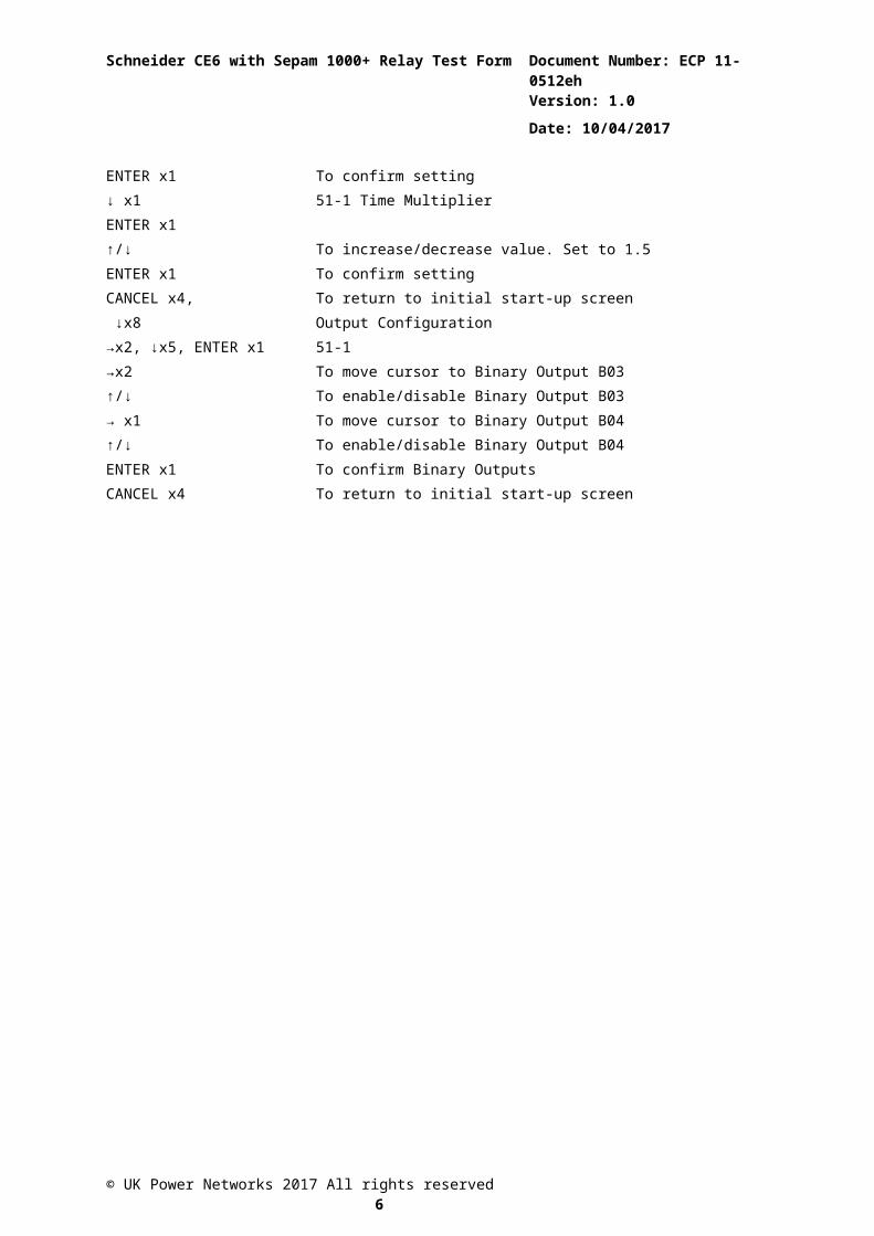
↓ x5 Current Protection→ x2, ↓ x2 51-1 ElementENTER x1, ↓ x1,ENTER x1 To enable the overcurrent element↓ x1, ENTER x1 51-1 Setting↑/↓ To increase/decrease value. Set to 0.4InENTER x1 To confirm settings↓ x1 51-1 Curve CharacteristicENTER x1↑/↓ To increase/decrease value. Set to IEC-NIENTER x1 To confirm setting↓ x1 51-1 Time MultiplierENTER x1↑/↓ To increase/decrease value. Set to 1.5ENTER x1 To confirm settingCANCEL x4, ↓x8
To return to initial start-up screenOutput Configuration
→x2, ↓x5, ENTER x1 51-1→x2 To move cursor to Binary Output B03↑/↓ To enable/disable Binary Output B03→ x1↑/↓ENTER x1
To move cursor to Binary Output B04To enable/disable Binary Output B04To confirm Binary Outputs
CANCEL x4 To return to initial start-up screen
© UK Power Networks 2017 All rights reserved 4
Schneider CE6 with Sepam 1000+ Relay Test Form Document Number: ECP 11-0512h
Version: 1.0
Date: 10/04/2017
A.4.4 Step 3 – Instantaneous Overcurrent
↓x5 Current Protection→ x2, ↓ x11, ENTER x1 50-1 Setting↓/↑ To increase/decrease value. Set to 4.0xInENTER x1 To confirm setting change↓x1 50-1 DelayENTER x1↑/↓ To increase/decrease value. Set to 0.5ENTER x1 To confirm setting changeCANCEL x4 To return to initial start-up screen
A.4.5 Step 4 – Earth Fault
↓x5, → x1 Phase Overcurrent→ x1, ↓x2 51-1 ElementENTER x1, ↓ x1, ENTER x1 To enable Overcurrent protectionCANCEL x1, ↓ x1 Derived E/F→ x1 51N-1 ElementENTER x1, ↑ x1, ENTER x1 To enable E/F protection↓ x1, ENTER x1 51N-1 Setting↓/↑ To increase/decrease value. Set to 0.3xInENTER x1 To confirm setting change↓x1 51N -1 Curve CharacteristicENTER x1↑/↓ To increase/decrease value. Set to IEC-NIENTER x1 To confirm setting↓x1 51N -1 Time MultiplierENTER x1↑/↓ To increase/decrease value. Set to 1.5ENTER x1 To confirm settingCANCEL x4, ↓x8 Output Configuration→x2, ↓x7, ENTER x1 51N-1→x2 To move cursor to Binary Output B03↑/↓→ x1
To enable/disable Binary Output B03To move cursor to Binary Output B04
↑/↓ENTER x1
To enable/disable Binary Output B04To confirm Binary Outputs
CANCEL x4 To return to initial start-up screen
© UK Power Networks 2017 All rights reserved 5
Schneider CE6 with Sepam 1000+ Relay Test Form Document Number: ECP 11-0512h
Version: 1.0
Date: 10/04/2017
A.4.6 Step 5 – Instantaneous Earth Fault
↓x5 Current Protection→ x1, ↓ x1 Derived E/F→ x1, ↓x9, ENTER x1 50N-1 Setting↓/↑ To increase/decrease value. Set to 2.0xInENTER x1 To confirm setting change↓x1 50N -1 DelayENTER x1↑/↓ To increase/decrease value. Set to 0.0ENTER x1 To confirm setting changeCANCEL x4 To return to initial start-up screen
The required relay settings have now been applied.
© UK Power Networks 2017 All rights reserved 6
Schneider CE6 with Sepam 1000+ Relay Test Form Document Number: ECP 11-0512h
Version: 1.0
Date: 10/04/2017
A.5 Communication Port
To set the relay using a communication port the following is required:
PC with Reydisp Evolution Version 7.1.5.6 or later Installed. (This can be downloaded from the Siemens website and found under the submenu ‘Software’) This software requires windows 2000-service pack 4 or above, or windows XP with service pack 2 or above and Microsoft.NET framework for tools.
The relay can be connected to Reydisp via any of the communication ports on the relay. Suitable communication Interface cable and converters are required depending on which port is being used.
A.5.1 Front USB connection
To connect a pc locally via the front USB port.
A.5.2 Rear RS485 connection
To connect a pc locally via the rear RS485 port.
© UK Power Networks 2017 All rights reserved 7
Schneider CE6 with Sepam 1000+ Relay Test Form Document Number: ECP 11-0512h
Version: 1.0
Date: 10/04/2017
A.6 Menu Structure
© UK Power Networks 2017 All rights reserved 8
Schneider CE6 with Sepam 1000+ Relay Test Form Document Number: ECP 11-0512h
Version: 1.0
Date: 10/04/2017
Appendix B – Schematic Drawings
© UK Power Networks 2017 All rights reserved 1
Schneider CE6 with Sepam 1000+ Relay Test Form Document Number: ECP 11-0512h
Version: 1.0
Date: 10/04/2017
© UK Power Networks 2017 All rights reserved 2
Schneider CE6 with Sepam 1000+ Relay Test Form Document Number: ECP 11-0512h
Version: 1.0
Date: 10/04/2017
© UK Power Networks 2017 All rights reserved 3


![[XLS]bendixradiofoundation.combendixradiofoundation.com/documents/Programs_Products.xls · Web viewRelay Unit EP 267 MR-26B Remote Control EP 316 Transmitter EP 1095 Direction Finder](https://static.fdocuments.net/doc/165x107/5b2d202c7f8b9ac56e8baa9c/xlsb-web-viewrelay-unit-ep-267-mr-26b-remote-control-ep-316-transmitter-ep.jpg)