ECODRIVE03 Drive for General Automation With … · Drive for General Automation With SERCOS-,...
42
ECODRIVE03 Drive for General Automation With SERCOS-, Analog- and Parallelinterface DOK-ECODR3-SGP-01VRS**-FVN1-EN-P Firmware-Version Notes: SGP 01VRS mannesmann Rexroth engineering Indramat 280282
Transcript of ECODRIVE03 Drive for General Automation With … · Drive for General Automation With SERCOS-,...

ECODRIVE03Drive for General Automation
With SERCOS-, Analog- and Parallelinterface
DOK-ECODR3-SGP-01VRS**-FVN1-EN-P
Firmware-Version Notes: SGP 01VRS
mannesmannRexroth
engineering
Indramat280282
About this documentation ECODRIVE03 SGP-01VRS
DOK-ECODR3-SGP-01VRS**-FVN1-EN-P
ECODRIVE03 Drive for General Automation with SERCOS, Analog andParallel Interfaces
Firmware Version FWA-ECODR3-SGP-01VRS-MS
DOK-ECODR3-SGP-01VRS**-FVN1-EN-P
• Box 72-01V-EN
• Based on: SGP 01V
• 209-0088-4325-01
This documentation is a supplement to the function description DOK-ECODR3-SGP-01VRS**-FKB1-EN-P: EDODRIVE03 Drive for GeneralAutomation with SERCOS, Analog and Parallel interfaces.
It describes the differences between ECODRIVE3 Version FWA-ECODR3-SGP-01VRS and the previous versions:
• FWA-ECODR3-ASE-04VRS
• FWA-ECODR3-SMT-01VRS
• FWA-DIAX-ELS-05VRS
Document identification of previous andpresent editions
ReleaseDate
Note
DOK-ECODR3-SGP-01VRS**-FVN1-EN-P 01.99 first release
INDRAMAT GmbH, 1999
Transmission as well as reproduction of this documentation, commercialuse or communication of its contents will not be permitted withoutexpressed written permission. Violation of these stipulations will requirecompensation. All rights reserved for the ensurance of the patent orregistered design. (DIN 34-1)
Changes in the content of the documentation and the delivery possibilitiesof the products are reserved
INDRAMAT GmbH • Bgm.-Dr.-Nebel-Str. 2 • D-97816 Lohr a. Main
Telephone 09352/40-0 • Tx 689421 • Fax 09352/40-4885
Abt. ECD (TH/OS)
This document is printed on chlorine-free bleached paper.
Title
Type of Documentation
Document code
Internal filing notation
What is the purpose of thisdocumentation
Editing sequence
Copyright
Liability
Publisher
Note
ECODRIVE03 SGP-01VRS
DOK-ECODR3-SGP-01VRS**-FVN1-EN-P
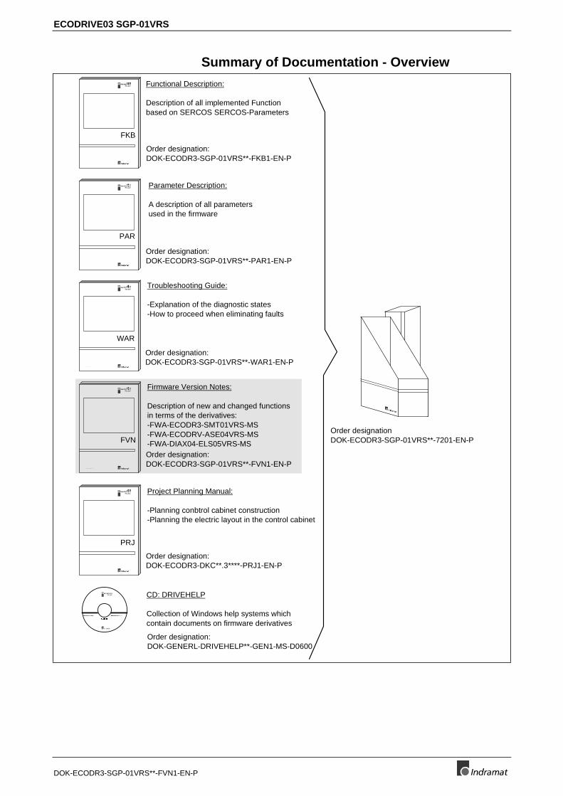
Summary of Documentation - Overview
Order designation:DOK-ECODR3-SGP-01VRS**-FKB1-EN-P
Order designation:DOK-ECODR3-SGP-01VRS**-PAR1-EN-P
Order designation:DOK-ECODR3-SGP-01VRS**-WAR1-EN-P
Order designation:DOK-ECODR3-SGP-01VRS**-FVN1-EN-P
Order designation:DOK-ECODR3-DKC**.3****-PRJ1-EN-P
2 8 2 8 0 1
FKB
2 8 2 8 0 1
PAR
2 8 2 8 0 1
WAR
2 8 2 8 0 1
FVN
2 8 2 8 0 1
PRJ
Functional Description:
Description of all implemented Functionbased on SERCOS SERCOS-Parameters
Parameter Description:
A description of all parametersused in the firmware
Troubleshooting Guide:
-Explanation of the diagnostic states-How to proceed when eliminating faults
Firmware Version Notes:
Description of new and changed functionsin terms of the derivatives:-FWA-ECODR3-SMT01VRS-MS-FWA-ECODRV-ASE04VRS-MS-FWA-DIAX04-ELS05VRS-MS
Project Planning Manual:
-Planning conbtrol cabinet construction-Planning the electric layout in the control cabinet
Order designationDOK-ECODR3-SGP-01VRS**-7201-EN-P
part number:282411Version:01Win3.1 andWin95&NT
(6-:),)04
CD: DRIVEHELP
Collection of Windows help systems whichcontain documents on firmware derivatives
Order designation:DOK-GENERL-DRIVEHELP**-GEN1-MS-D0600
About this documentation ECODRIVE03 SGP-01VRS
DOK-ECODR3-SGP-01VRS**-FVN1-EN-P
Notes
ECODRIVE03 SGP-01VRS Contents I
DOK-ECODR3-SGP-01VRS**-FVN1-EN-P
Contents
1 General Information 1-11.1 Product Family ..................................................................................................................................... 1-1
1.2 Documentation..................................................................................................................................... 1-2
1.3 Notes on Replacing the Firmware........................................................................................................ 1-2
1.4 Release notes ...................................................................................................................................... 1-4
2 Differences to FWA-ECODR3-SMT-01VRS 2-12.1 New Functions ..................................................................................................................................... 2-1
Operating Modes........................................................................................................................... 2-1
Master Axis Encoder ..................................................................................................................... 2-2
Measuring Wheel Mode Command .............................................................................................. 2-3
2.2 Changed Functions.............................................................................................................................. 2-3
PL displayed when switching on the control voltage..................................................................... 2-3
Password....................................................................................................................................... 2-3
Permanently Configured Status Messages................................................................................... 2-3
Configurable Signal Status Word .................................................................................................. 2-3
Measuring Systems....................................................................................................................... 2-3
Analog Outputs.............................................................................................................................. 2-3
Probe Input Feature ...................................................................................................................... 2-4
Programmable Limit Switch .......................................................................................................... 2-4
Cycle Time .................................................................................................................................... 2-4
2.3 Functions Not Implemented ................................................................................................................. 2-4
3 Differences to FWA-ECODRV-ASE-04VRS 3-13.1 New Functions ..................................................................................................................................... 3-1
Error Memory and Operating Hour Counter.................................................................................. 3-1
New Component to Communicate with the Parameter Interface.................................................. 3-1
Permanently Configured Status Messages................................................................................... 3-2
Language switch to French, Spanish or Italian ............................................................................. 3-2
Multiplex Channel.......................................................................................................................... 3-2
Motor Types .................................................................................................................................. 3-3
Operating Modes........................................................................................................................... 3-3
Measuring Systems....................................................................................................................... 3-4
Current Limits................................................................................................................................ 3-5
Drive-Side Error Reaction ............................................................................................................. 3-7
Automatic Control Loop Settings................................................................................................... 3-7
Velocity Mix Factor........................................................................................................................ 3-8
Freely-Configurable Signal Status Word....................................................................................... 3-8
Freely-Configurable Signal Control Word ..................................................................................... 3-8

II Contents ECODRIVE03 SGP-01VRS
DOK-ECODR3-SGP-01VRS**-FVN1-EN-P
Analog Inputs ................................................................................................................................ 3-8
Oscilloscope Function ................................................................................................................... 3-9
Probe Function.............................................................................................................................. 3-9
Detect Marker Position Command ................................................................................................ 3-9
Park Axis Command ..................................................................................................................... 3-9
Programmable Limit Switch ........................................................................................................ 3-10
Encoder Emulation...................................................................................................................... 3-10
3.2 Changed Functions............................................................................................................................ 3-10
Password..................................................................................................................................... 3-10
Command communication via SERCOS Interface ..................................................................... 3-10
Operating Modes......................................................................................................................... 3-11
Travel range limit......................................................................................................................... 3-11
E-Stop Function........................................................................................................................... 3-11
Controller Structure ..................................................................................................................... 3-12
Velocity Control Loop Monitoring ................................................................................................ 3-14
Drive Halt..................................................................................................................................... 3-14
Drive-Controlled Homing............................................................................................................. 3-14
Analog Output ............................................................................................................................. 3-14
Serial Communication ................................................................................................................. 3-15
4 Differences to FWA-DIAX-ELS-05VRS 4-14.1 New Functions ..................................................................................................................................... 4-1
Multiplex Channel.......................................................................................................................... 4-1
Analog Command Communications ............................................................................................. 4-1
Parallel Command Communication .............................................................................................. 4-1
Firmware Loader ........................................................................................................................... 4-1
Operating Modes........................................................................................................................... 4-1
Automatic Control Loop Settings................................................................................................... 4-2
Configurable Signal Control Word................................................................................................. 4-3
4.2 Changed Functions.............................................................................................................................. 4-3
PL displayed when switching on the control voltage..................................................................... 4-3
Password....................................................................................................................................... 4-3
List of Diagnostic Numbers ........................................................................................................... 4-3
Permanently Configured Status Messages................................................................................... 4-3
Compatibility Class C .................................................................................................................... 4-4
Motor Holding Brake ..................................................................................................................... 4-4
Magnetization Current for Asynchronous Motors.......................................................................... 4-4
Commutation Settings................................................................................................................... 4-4
Operating Modes........................................................................................................................... 4-4
Measuring Systems....................................................................................................................... 4-4
Evaluating an Absolute Measuring System................................................................................... 4-4
Travel Range Monitoring............................................................................................................... 4-5
Master axis encoder...................................................................................................................... 4-5
E-stop Function ............................................................................................................................. 4-5
Load Base Values ......................................................................................................................... 4-5
Velocity Control Loop Monitor with Off Capabilities ...................................................................... 4-5
Drive Halt....................................................................................................................................... 4-5
ECODRIVE03 SGP-01VRS Contents III
DOK-ECODR3-SGP-01VRS**-FVN1-EN-P
Drive-Controlled Homing............................................................................................................... 4-5
Probe Input Feature ...................................................................................................................... 4-6
Programmable Limit Switch .......................................................................................................... 4-6
Encoder Emulation........................................................................................................................ 4-6
Command Measuring Wheel Mode .............................................................................................. 4-6
Serial Communication ................................................................................................................... 4-6
4.3 Functions Not Implemented ................................................................................................................. 4-6

IV Contents ECODRIVE03 SGP-01VRS
DOK-ECODR3-SGP-01VRS**-FVN1-EN-P
Notes

ECODRIVE03 SGP-01VRS Versionsnotes 1-1
DOK-ECODR3-SGP-01VRS**-FVN1-EN-P
1 General Information
1.1 Product Family
The product release description refers to the product family:
ECODRIVE03
Drive for General Automation With
SERCOS, Analog and Parallel Interfaces
FWA-ECODR3-SGP-01VRS-MS
The following drive controls can be operated with this software:
DKC11.3-040-7-FW DKC11.3-100-7-FW DKC01.3-040-7-FW DKC01.3-100-7-FW DKC02.3-040-7-FW DKC02.3-100-7-FW
This document describes the differences between ECODRIVE03 versionFWA-ECODR3-SGP-01VRS and the previous ECODRIVE version FWA-ECODRV-ASE-04VRS or FWA-ECODR3-SMT-04VRS and FWA-DIAX-ELS-05VRS.
1-2 Versionsnotes ECODRIVE03 SGP-01VRS
DOK-ECODR3-SGP-01VRS**-FVN1-EN-P
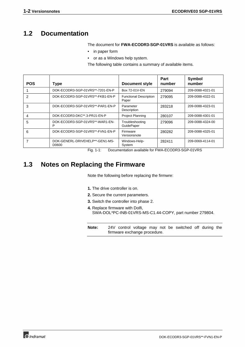
1.2 Documentation
The document for FWA-ECODR3-SGP-01VRS is available as follows:
• in paper form
• or as a Windows help system.
The following table contains a summary of available items.
POS Type Document stylePartnumber
Symbolnumber
1 DOK-ECODR3-SGP-01VRS**-7201-EN-P Box 72-01V-EN 279094 209-0088-4321-01
2 DOK-ECODR3-SGP-01VRS**-FKB1-EN-P Functional DescriptionPaper
279095 209-0088-4322-01
3 DOK-ECODR3-SGP-01VRS**-PAR1-EN-P ParameterDescription
283218 209-0088-4323-01
4 DOK-ECODR3-DKC**.3-PRJ1-EN-P Project Planning 280107 209-0088-4301-01
5 DOK-ECODR3-SGP-01VRS**-WAR1-EN-P
TroubleshootingGuidePaper
279096 209-0088-4324-00
6 DOK-ECODR3-SGP-01VRS**-FVN1-EN-P FirmwareVersionsnote
280282 209-0088-4325-01
7 DOK-GENERL-DRIVEHELP**-GEN1-MS-D0600
Windows-Help-System
282411 209-0069-4114-01
Fig. 1-1: Documentation available for FWA-ECODR3-SGP-01VRS
1.3 Notes on Replacing the Firmware
Note the following before replacing the firmwre:
1. The drive controller is on.
2. Secure the current parameters.
3. Switch the controller into phase 2.
4. Replace firmware with Dolfi, SWA-DOL*PC-INB-01VRS-MS-C1.44-COPY, part number 279804.
Note: 24V control voltage may not be switched off during thefirmware exchange procedure.
ECODRIVE03 SGP-01VRS Versionsnotes 1-3
DOK-ECODR3-SGP-01VRS**-FVN1-EN-P
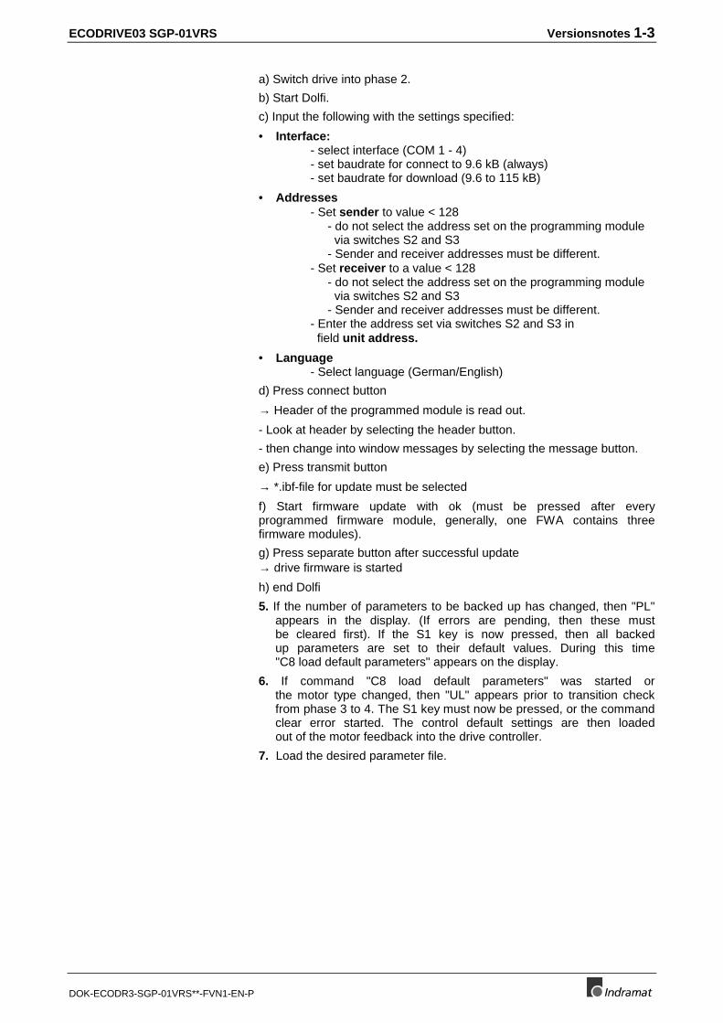
a) Switch drive into phase 2.
b) Start Dolfi.
c) Input the following with the settings specified:
• Interface:- select interface (COM 1 - 4)- set baudrate for connect to 9.6 kB (always)- set baudrate for download (9.6 to 115 kB)
• Addresses- Set sender to value < 128
- do not select the address set on the programming module via switches S2 and S3- Sender and receiver addresses must be different.
- Set receiver to a value < 128- do not select the address set on the programming module via switches S2 and S3- Sender and receiver addresses must be different.
- Enter the address set via switches S2 and S3 in field unit address.
• Language- Select language (German/English)
d) Press connect button
→ Header of the programmed module is read out.
- Look at header by selecting the header button.
- then change into window messages by selecting the message button.
e) Press transmit button
→ *.ibf-file for update must be selected
f) Start firmware update with ok (must be pressed after everyprogrammed firmware module, generally, one FWA contains threefirmware modules).
g) Press separate button after successful update→ drive firmware is started
h) end Dolfi
5. If the number of parameters to be backed up has changed, then "PL" appears in the display. (If errors are pending, then these must be cleared first). If the S1 key is now pressed, then all backed up parameters are set to their default values. During this time "C8 load default parameters" appears on the display.
6. If command "C8 load default parameters" was started or the motor type changed, then "UL" appears prior to transition check from phase 3 to 4. The S1 key must now be pressed, or the command clear error started. The control default settings are then loaded out of the motor feedback into the drive controller.
7. Load the desired parameter file.

1-4 Versionsnotes ECODRIVE03 SGP-01VRS
DOK-ECODR3-SGP-01VRS**-FVN1-EN-P
1.4 Release notes
Firmware version FWA-ECODR3-SGP-01V09 represents the first officialedition of version 01. It was released on
29.01.1999
The following drive controllers can be operated with the releasedsoftware:
• DKC11.3-040-7-FW, DKC11.3-100-7-FW
• DKC01.3-040-7-FW, DKC01.3-100-7-FW
• DKC02.3-040-7-FW, DKC02.3-100-7-FW
Note: To commission drive firmware version FWA-ECODRV03-SGP-01VRS-MS then DriveTop version SWA-DTOP***-INB-05VRS-MS-C1,44-COPY or higher than SWA-S*TOP*-INB-04T14-MS-C1,44-COPY is needed.
ECODRIVE03 SGP-01VRS Differences to FWA-ECODR3-SMT-01VRS 2-1
DOK-ECODR3-SGP-01VRS**-FVN1-EN-P
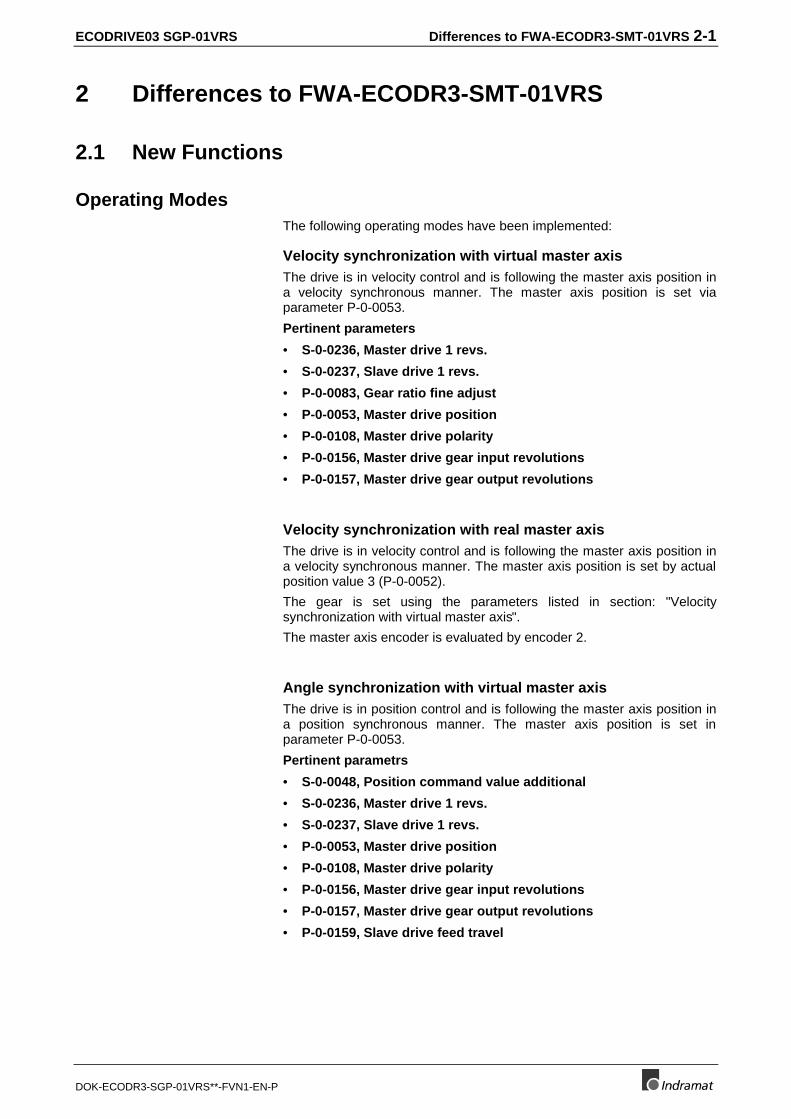
2 Differences to FWA-ECODR3-SMT-01VRS
2.1 New Functions
Operating ModesThe following operating modes have been implemented:
Velocity synchronization with virtual master axisThe drive is in velocity control and is following the master axis position ina velocity synchronous manner. The master axis position is set viaparameter P-0-0053.
Pertinent parameters
• S-0-0236, Master drive 1 revs.
• S-0-0237, Slave drive 1 revs.
• P-0-0083, Gear ratio fine adjust
• P-0-0053, Master drive position
• P-0-0108, Master drive polarity
• P-0-0156, Master drive gear input revolutions
• P-0-0157, Master drive gear output revolutions
Velocity synchronization with real master axisThe drive is in velocity control and is following the master axis position ina velocity synchronous manner. The master axis position is set by actualposition value 3 (P-0-0052).
The gear is set using the parameters listed in section: "Velocitysynchronization with virtual master axis".
The master axis encoder is evaluated by encoder 2.
Angle synchronization with virtual master axisThe drive is in position control and is following the master axis position ina position synchronous manner. The master axis position is set inparameter P-0-0053.
Pertinent parametrs
• S-0-0048, Position command value additional
• S-0-0236, Master drive 1 revs.
• S-0-0237, Slave drive 1 revs.
• P-0-0053, Master drive position
• P-0-0108, Master drive polarity
• P-0-0156, Master drive gear input revolutions
• P-0-0157, Master drive gear output revolutions
• P-0-0159, Slave drive feed travel

2-2 Differences to FWA-ECODR3-SMT-01VRS ECODRIVE03 SGP-01VRS
DOK-ECODR3-SGP-01VRS**-FVN1-EN-P
Angle synchronizsation with real master axisThe drive is in position control and is following the master axis position ina position synchronous manner. The master axis position is set by actualThe gear is set using the parameters listed in section: "Anglesynchronization with virtual master axis".
The master axis encoder is evaluated by encoder 2.
Electronic cam with virtual master axisThe drive is in position control. The profile access angle of the cam profileis generated out of the master axis position. The profile value is evaluatedusing the hub. The results are read to the position controller and the drivefollows the cam profile. The master axis position is specified by the actualpositon value 3 (P-0-0052).
Pertinent parameters
• S-0-0048, Position command value additional
• P-0-0053, Master drive position
• P-0-0061, Angle offset begin of profile
• P-0-0072, Cam shaft profile 1
• P-0-0085, Dynamical phase offset
• P-0-0088, Cam shaft control
• P-0-0089, Cam shaft status
• P-0-0092, Cam shaft profile 2
• P-0-0093, Cam shaft distance
• P-0-0094, Cam shaft switch angle
• P-0-0108, Master drive polarity
• P-0-0144, Cam shaft distance switch angle
• P-0-0156, Master drive gear input revolutions
• P-0-0157, Master drive gear output revolutions
• P-0-0158, Phase offset velocity
Electronic cam with real master axisThe drive is in position control. The profile access angle of the cam profileis generated out of the master axis position. The profile value is evaluatedusing the hub. The results are read to the position controller and the drivefollows the cam profile. The master axis position is specified by the actualpositon value 3 (P-0-0052).
The gear is set with the parameters listed in section: "Electronic cam withvirtual master axis".
The master axis encoder is evaluated by encoder 2.
Master Axis EncoderEncoder 2 can be parametrized to function like a master axis encoder.Only encoders with binary lines may be used. Incremental encoders arealso possible in addition to single or multiturn encoders. This includesautomatic detection of the zero pulse followed by transition from P-0-0052to offset P-0-0087. Actual position value 3 is smoothed via the PT1 filter;the time constant is set with parameter P-0-0186, Actual Position value3, smoothing time.
ECODRIVE03 SGP-01VRS Differences to FWA-ECODR3-SMT-01VRS 2-3
DOK-ECODR3-SGP-01VRS**-FVN1-EN-P
Measuring Wheel Mode CommandA roll feed drive conveys or moves material that is processed later ondown the line (e.g., tin cutting). In this case, a motor encoder is notsuitable for measuring lengths of pieces of material if there is some slipbetween the material and the drive. Instead, it makes sense to use anoptional encoder, the measuring wheel encoder. Ideally, there is no slip inthe connection to the material with such an encoder and this sections ofthe material can be precisely measured.
2.2 Changed Functions
PL displayed when switching on the control voltageIf PL is displayed after the control voltage is switched on, then firmwareversion has been replaced and the drive wants to overwrite all parameterswith the basic parameters. The base parameters can only be loaded bypresing the S1 key. It is not possible to communicate with the drive forthis entire length of time.
PasswordThose parameters protected by the user’s password are entered inparameter S-0-0279, IDN-list of password-protected operation data.
Permanently Configured Status MessagesThe permanently configured status message S-0-0013, Class 3diagnostics bit3: "Torque >= torque threshold" is not longer supported.
The configurable signal status word (S-0-0182, Manufacturer class 3diagnostics) contains:
• bit2- ready
• bit3 -warning.
The status messages for the synchronous operating modes
• bit 8 - in synchronisation
• bit 9 - synchronization completed
have been added.
Configurable Signal Status WordIn SERCOS units, bits 0 and 1 of the signal status words (S-0-0144) areillustrates at the digital outputs „Ready“ and „Warning“. With „Load baseparameters“ the signal status word bits „Ready“ and „Warning“ areconfigured out of parameter S-0-0182.
Measuring SystemsP-0-0185, Function of encoder 2 identifies the use. Possible settings are0, 1, 2 and 3 (measuring wheel encoder).
Analog OutputsThe selection of the signals has been expanded.
2-4 Differences to FWA-ECODR3-SMT-01VRS ECODRIVE03 SGP-01VRS
DOK-ECODR3-SGP-01VRS**-FVN1-EN-P
Probe Input FeatureThe following signals can be recorded:
• Master axis position with and without window
• Actual position value 3 with and without window
• Actual position values 1 and 2 with window
Programmable Limit SwitchThere are 16 cam switch points avaialble to the cam switch group. Forevery one millisecond, one cam switch point is computed.
Cycle TimeThe cycle time of the internal command value generating process of theposition controller is 1ms.
2.3 Functions Not Implemented
• Main spindle applications: spindle positioning.
• Servo-application: running to end limit.
ECODRIVE03 SGP-01VRS Differences to FWA-ECODRV-ASE-04VRS 3-1
DOK-ECODR3-SGP-01VRS**-FVN1-EN-P
3 Differences to FWA-ECODRV-ASE-04VRS
3.1 New Functions
Error Memory and Operating Hour CounterOperating hour counters and error memory were used in the past to storeclass 1 diagnostics errors and the number of operating hours of themachine in the form of parameters:
• P-0-0190, Operating hours control section
• P-0-0191, Operating hours power section
• P-0-0192, Error recorder, diagnosis number
• P-0-0193, Error recorder, operating hours control section
These are stored in the amplifier EEPROM. The user cannot write accessthem.
New Component to Communicate with the Parameter Interface
Additional ID number listsFor communication between drive firmware and parameter interface, newID number lists have been introduced:
• S-0-0018, IDN-list of operation data for CP2
• S-0-0019, IDN-list of operation data for CP3
• S-0-0025, IDN-list of all procedure commands
• S-0-0292, List of all operating modes
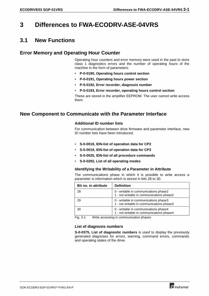
Identifying the Writability of a Parameter in AttributeThe communications phase in which it is possible to write access aparameter is information which is stored in bits 28 to 30.
Bit no. in attribute Definition
28 0 - writable in communications phase21 - not writable in communications phase2
29 0 - writable in communications phase31 - not writable in communications phase3
30 0 - writable in communications phase41 - not writable in communications phase4
Fig. 3-1: Write accessing in communication phases
List of diagnosis numbersS-0-0375, List of diagnostic numbers is used to display the previouslygenerated diagnoses for errors, warning, command errors, commandsand operating states of the drive.
3-2 Differences to FWA-ECODRV-ASE-04VRS ECODRIVE03 SGP-01VRS
DOK-ECODR3-SGP-01VRS**-FVN1-EN-P
Permanently Configured Status MessagesThe following general and operating-mode specific status messages havebeen newly implemented in parameters S-0-0013, Class 3 diagnosticsand S-0-0182, Manufacturer class 3 diagnostics.
In S-0-0013, Class 3 diagnostics :
• actual velocity = command velocity
• | actual velocity | < velocity threshold
• | Md | > Mdx
• | Md | > Mdgrenz
• | P | >Px
• target position reached
In S-0-0182, Manufacturer class 3 diagnostics :
• IZP (target position reached & IN_POSITION & IN_STANDSTILL)
• IN_TARGETPOSITION
• drive halt acknowledged
• end position reached
• ready
• warning
Message „IN-MOTION“ has been replaced with |nist| < S-0-0124,Standstill window and thus inverted.
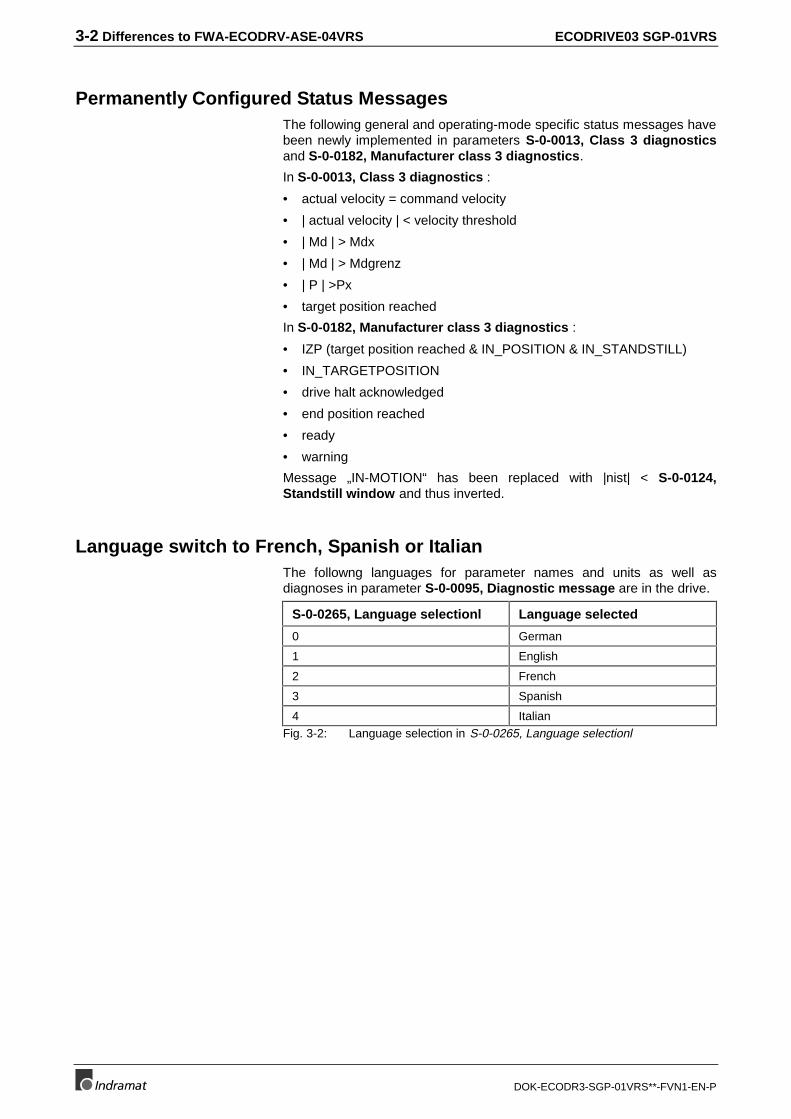
Language switch to French, Spanish or ItalianThe followng languages for parameter names and units as well asdiagnoses in parameter S-0-0095, Diagnostic message are in the drive.
S-0-0265, Language selectionl Language selected
0 German
1 English
2 French
3 Spanish
4 ItalianFig. 3-2: Language selection in S-0-0265, Language selectionl
ECODRIVE03 SGP-01VRS Differences to FWA-ECODRV-ASE-04VRS 3-3
DOK-ECODR3-SGP-01VRS**-FVN1-EN-P
Multiplex ChannelThe limit cyclical data channel can be upgraded with the multiplexchannel. It is also possible to cyclically access list elements by usingindex switching.
It is possible, with the multiplex channel to:
• cyclically exchange more parameter contents despite a limitedmaximum number of transmittable bytes in the master data telegramand drive telegram;
• access individual list elements with the use of both indices S-0-0362and S-0-0366;
• transmit the multiplexed data with a cycle time of Tscyc * number ofmultiplexed data by incrementing index S-0-0368 in each cycle;
• generate index switching in operating mode terms and thus onlytransmit the parameters needed for the activated operating mode.
Motor TypesThe following synchronous and asynchronous motors can also beoperated in addition to the MKD synchronous motors.
MHD LAF/LAR
MKE LSF
2AD/1MB/ADF MBS
synchronous kit motor
MHD, MKD and MKE motors are automatically detected and those motorparameters which are needed are set. All other motor types must be setby inputting the relevant parameters.
Motor holding brake controlParameters
• P-0-0525, Type of motor brake
• P-0-0526, Brake control delay are used to control the holding brake.
These parameters are automatically set in MHD, MKD and MKE motors.The brake current is not monitored.
Load-side motor encoder in rotary asynchronous motorsIf motor type "2" or"6" is set (rotary asynchronous motor), then the motorencoder can be mounted load side and operated there as well. The loadside motor encoder is parametrized using parameters from encoder 2(the optional encoder):
• S-0-0115, Position feedback 2 type
• S-0-0117, Feedback 2 Resolution
• P-0-0075, Feedback type 2
P-0-0074, Feedback type 1 must be parametrized with "0". Parameter P-0-0121, Velocity mix factor Feedback 1 & 2 must be set to 100%.
3-4 Differences to FWA-ECODRV-ASE-04VRS ECODRIVE03 SGP-01VRS
DOK-ECODR3-SGP-01VRS**-FVN1-EN-P
Operating ModesFour operating modes (one main and three auxiliary modes) can besimultaneously selected. Which of the four is active depends on themaster control word which is selected. The higher ranking controlperforms both the setting and the selection.
The following modes can be set in the drive:
• torque control
• velocity control
• position control with cyclical position command
• (absolute) drive-internal interpolation
• relative drive-internal interpolation
• positioning block mode
• jogging
• position control with step motor interface
• velocity synchronization with virtual master axis
• velocity synchronization with real master axis
• phase synchronization with virtual master axis
• phase synchronization with real master axis
• electronic cam shaft with virtual master axis
• electronic cam shaft with real master axis
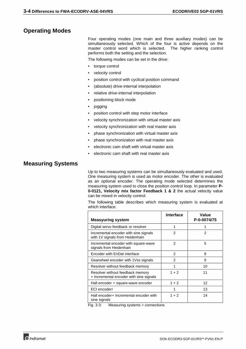
Measuring SystemsUp to two measuring systems can be simultaneously evaluated and used.One measuring system is used as motor encoder. The other is evaluatedas an optional encoder. The operating mode selected determines themeasuring system used to close the position control loop. In parameter P-0-0121, Velocity mix factor Feedback 1 & 2 the actual velocity valuecan be mixed in velocity control.
The following table describes which measuring system is evaluated atwhich interface.
Measyuring systemInterface Value
P-0-0074/75
Digital servo feedback or resolver 1 1
Incremental encoder with sine signalswith 1V signals from Heidenhain
2 2
Incremental encoder with square-wavesignals from Heidenhain
2 5
Encoder with EnDat interface 2 8
Gearwheel encoder with 1Vss signals 2 9
Resolver without feedback memory 1 10
Resolver without feedback memory+ Incremental encoder with sine signals
1 + 2 11
Hall encoder + square-wave encoder 1 + 2 12
ECI encoderr 1 13
Hall encoder+ Incremental encoder withsine signals
1 + 2 14
Fig. 3-3: Measuring systems > connections

ECODRIVE03 SGP-01VRS Differences to FWA-ECODRV-ASE-04VRS 3-5
DOK-ECODR3-SGP-01VRS**-FVN1-EN-P
Absolute EncoderBoth motor encoder and optional encoders can be absolute encoders.Whether the measuring system is evaluated as an absolute encoder ornot, depends on
• the travel range set in S-0-0278, Maximum travel range (withabsolute format of position data) or
• the modulo value set in S-0-0103, Modulo value (with modulo formatof position data).
This means it is now possible:
• to handle singleturn encoders as absolute encoders and
• to switch off an absolute encoder evaluation for multiturn encoders.
Programmable drive-internal position resolutionThe resolution of the drive-internal position data is no longer dependenton the motor encoder type, but can be set via parameter S-0-0278,Maximum travel range. The maximum resolution is 215 per encoderperiod, minimum 2². The computed resoluton for encoders 1 and 2 isdisplayed in parameters S-0-0256, Multiplication 1 und S-0-0257,Multiplication 2.
Note: The drive-internal position resolution mentioned here does notidentify the format and unit in which the position data aredisplayed. This is still set in parameter S-0-0076, Positiondata scaling type.
The drive-side resolution, in form of the number of increments per motorrevolution of a rotary motor encoder, for example, is computed in terms ofS-0-0116, Feedback 1 Resolution * S-0-0256, Multiplication 1.
The function supports
• the increase of drive-internal resolution of position data with smalltravel paths and high resolution requirements as well as
• to decrease the resolution in favor of the possible travel range.
Note: The per "Load default value" activated resolution generallymeets demands in terms of possible travel range withsufficiently large position resolution.
Current LimitsThe dynamic current limit no longer implements the overload factor P-0-0006, Overload factor, but rather the temperature model of the amplifierpowerstage and the motor. The maximum available current, includinglimits, is displayed in parameter P-0-4046, Active peak current in termsof the dynamic current limit. The available continuous current is displayedin P-0-4045, Active permanent current. This value depends on theswitching frequency which has been set.

3-6 Differences to FWA-ECODRV-ASE-04VRS ECODRIVE03 SGP-01VRS
DOK-ECODR3-SGP-01VRS**-FVN1-EN-P
Monitoring Amplifier OverloadThe thermal load of the controller endstage is performed with atemperature model. The thermal load is displayed in parameter P-0-0141,Thermal drive load. A setting in a parameter is no longer necessary. Ifthe drive limits the effective peak current because of the amplifieroverload, then warning E257 Continuous current limit active isgenerated and bit 0 (overload warning) is set in S-0-0012, Class 2diagnostics.
Monitoring Motor OverloadThe fourfold motor standstill current is allowed for 400msec. The 2.2 foldone is continuously allowed. If the motor overload limit is active, thenwarning E225 Motor overload is generated and bit 0 (overload warning)is set in S-0-0012, Class 2 diagnostics.
Drive-Side Error ReactionThe reaction of the drive to detected errors has been expanded asfollows:
• Using parameter P-0-0119, Best possible deceleration it is possibleto set the reaction of the drive to non-fatal and interface errors. Inaddition to the reactions, "Velocity command to zero", "Torque tozero", "Velocity to zero with ramp and filter" and "Jerk limit" are alsoused.
• "NC reaction with error". If a non-fatal error occurs, then the drive errorreaction can be delayed for 30 seconds. Seting in parameter P-0-0117, NC reaction on error.
• In parameter P-0-0118, Power off on error settings can be made fora) the time that power should be switched on, b) shutdown of powerwith fault, c) execution of a package reaction and d) reaction of thedrive to DC bus undervoltage.
Automatic Control Loop SettingsThe velocity and position control loops are completely automaticallyparametrized with the automatic control loop settings.
This uses the new command "D900 Command automatic loop tuning"in the drive.
In conjunction with DriveTop the command "D9 Automatic control loopsettings" can be started in the DriveTop dialog "Parameter / Automaticcontrol loop settings".
The user can influence the resulting control loop dynamics by means ofthe so-called attenuating factor. This means that no technical knowledgeis needed to make further control loop settings.
Additionally, at the end of the control loop setting, the determined loadmoment of inertia and the maximum parametrizable accel are displayedand stored in a parameter.
Note: To optimize the control loop, it is necessary to move an axis!
Monitoring thermal controllerload with a temperature model
of the endstage
Monitoring thermal motor loadwith temperature model of motor
ECODRIVE03 SGP-01VRS Differences to FWA-ECODRV-ASE-04VRS 3-7
DOK-ECODR3-SGP-01VRS**-FVN1-EN-P
Velocity Mix FactorWith the help of the velocity mix factor, the actual velocity value used forvelocity control can be put together based on motor and externalmeasuring systems. This can be advantageous if the coupling unitsbetween motor and load are subject to backlash or torsion.
Use parameter P-0-0121, Velocity mix factor Feedback 1 & 2 to set themixing relationship.
Freely-Configurable Signal Status WordA freely configurable signal status word has been used. It can be definedvia parameters:
• S-0-0026, Configuration list signal status word
• S-0-0328, Assign list signal status word
This defines which bit of which parameter is configured in the parameter.
• S-0-0144, Signal status word
Up to 16 bits can be configured. Generating the collective message S-0-0144 only takes place once in each interface cycle.
The digital outputs of DKC01.3 correspond to bits 0..9 of the signal statusword.
Freely-Configurable Signal Control WordA freely configurable signal status word has been implemented. It can bedefined via parameters:
• S-0-0027, Configuration list signal control word and
• S-0-0329, Assign list signal control word
This defines which bit of which parameter is configured in the parameter.
• S-0-0145, Signal control word
Up to 16 bits can be configured. The collective message is evaluatedonce in every interface cycle.
The digital outputs of DKC01.3 correspond to bits 0 to 9 of the signalcontrol word.
Analog InputsUsing the function Analog inputs it is possible to:
• enter some parameters of the drive with variable scaling viaanalog/digital converters. (Parameter P-0-0212, Analog inputs, IDNlist of assignable parameters, P-0-0213, Analog input 1,assignment, P-0-0214, Analog input 1, scaling per 10V full scale,P-0-0215, Analog input 2, assignment and P-0-0216, Analog input2, scaling per 10V full scale, new)
• or assign an offset to analog input signals (parameter P-0-0217,Analog input 1, offset and P-0-0218, Analog input 2, offset new).
Analog input 1 is processed every 500 usec, input 2 only every 8 msec.
3-8 Differences to FWA-ECODRV-ASE-04VRS ECODRIVE03 SGP-01VRS
DOK-ECODR3-SGP-01VRS**-FVN1-EN-P
Oscilloscope FunctionWith the oscilloscope function, specific signals of the drive such as
• S-0-0051, Position feedback 1 value or S-0-0053, Positionfeedback 2 value,
• S-0-0040, Velocity feedback value
• S-0-0080, Torque/Force command
• S-0-0347, Speed deviation
• S-0-0189, Following error
can be stored in 2*512-deep measurand lists. A triggering event is theresult either of thresholds or they are due to something external that canbe parametrized in the drive for position, velocity or torque data. Anoscilloscope function can be implemented by using the triggeringstipulations, reading the measurand list and graphically illustrating themeasurands stored therein by using a parametrization interface. It ispossible to illustrate contour accuracy by superimposing the measuringresults of axes that are interpolating with each other.
Probe FunctionThere are two probe inputs on the drive. This function stores signals from:
• actual position values 1 or 2 with or without window
• relative drive-internal time
• actual position values 3 1 or 2 with or without window
• master axis position 1 or 2 with or without window
at the time the switching edge of this probe occurs. They are stored in therelevant parameters. By preselecting, it is fixed whether the positive ornegative edge of the probe is evaluated. Each time the edge occurs, thedifference between the measurand for the positive and that of thenegative edge is stored in the parameter set for the measuranddifference.
Detect Marker Position CommandCorrect detection and the position of the reference marker of anincremental measuring system can be detected by using the command P-0-0014, D500 Command determine marker position. The position ofthe marker is displayed in parameter S-0-0173, Marker position A. Thecommand is also used to operate gantry axes with external measuringsystems as well as to examine the error-free detection of referencemarkers.
Park Axis CommandCommand S-0-0139, D700 Command Parking axis was used. It is onlypossible to write access this command in communications phase 2. If thiscommand is activated, then all the monitoring activities of command S-0-0128, C200 Communication phase 4 transition check are notconducted. Message "PA" appears on the 7-segment display. A phaseregression deactivates this command (as is the case with all othercommands).
ECODRIVE03 SGP-01VRS Differences to FWA-ECODRV-ASE-04VRS 3-9
DOK-ECODR3-SGP-01VRS**-FVN1-EN-P
Programmable Limit SwitchUp to 16 position-dependent cams can be realized with the functiondynamic programmable limit switch. The actual position value 1 can beused as a reference signal (motor encoder) or 2 (optional encoder). Thereis one on and one off threshold for each cam. If an off threshold is smallerthan the on threshold, then the cam is inverted. There is also a separatelyprogrammable prehold time for each cam with which the reference signalcan be corrected in terms of the velocty.
Encoder EmulationWith function encoder emulation it is possible to emulate
• actual position value 1
• and actual position value 2
• the command position value
• master axis value
• actual position value 3
in the form of
• SSI signals or
• TTL signals (incremental encoder).
3.2 Changed Functions
PasswordThe password function has been modified so that
• by inputting a customer password, not all parameters of the drivebecome write protected but instead only those parameters that are inparameter S-0-02792, IDN-list of password-protected operationdata. These are precisely those parameters stored in theprogramming module.
Command communication via SERCOS InterfaceCommunication via SERCOS interface has been modified as follows:
• if SERCOS communication is not active and if there are no edges atthe LWL inputs, then the drive goes into phase 4. The drive behaveslike an analog unit (drive enable and drive halt via hardware inputs arepossible).
• SERCOS compliance class C
• Multiplex channel for reading and writing data are not needed in everycycle and are not dependent on the active mode. Individual elementsof the list parameters can also be read/write. (Als check the newfunction: "Multiplex channel".)

3-10 Differences to FWA-ECODRV-ASE-04VRS ECODRIVE03 SGP-01VRS
DOK-ECODR3-SGP-01VRS**-FVN1-EN-P
Operating Modes
Position Block ModeThe following modifications have been made here:
• Mode"Run slow" is activated in bit 1 of parameter P-0-4060, Processblock control word and no longer in P-0-4027, Function parameter.
JoggingThe parameters effecting accel and jerk limit values are parameters
• S-0-0260, Positioning Acceleration and
• S-0-0193, Positioning Jerk
Note: Activating "Run slow" no longer works in jogging mode. Onlythe velocity set in P-0-4030, Jog velocity is effective.
Operating mode cyclical position controlThe command value is quadratically interpolated for the position controlloop in the case of position control to cyclical position command values.The position controller cycle time equals 1ms.
Travel range limitWhether the travel range limit switch input is active or not can be checkedin parameter P-0-0222, Status Inputs travel range limits.
E-Stop FunctionThe E-stop function was changed so that
• in bits 1 and 2 of P-0-0008, Activation E-Stop function the reactionof the drive upon actuation of the E-stop input can be selected and
• the status of the E-stop input (active / not active) is displayed inparameter P-0-0223, Status Input E-Stop function.
P-0-0008, Activating the E-Stop function
Bit 0 : Activating E-Stop0: inactive1: active
Bit 1 : Error class upon interpretation as error (bit 2 = 0)
0: best possible decel (P-0-0119)1: velocity command to zero
Bit 2 : Interpretation0: as nonfatal error1: fatal warning
Fig. 3-4: P-0-0008, Activation of the E-stop function

ECODRIVE03 SGP-01VRS Differences to FWA-ECODRV-ASE-04VRS 3-11
DOK-ECODR3-SGP-01VRS**-FVN1-EN-P
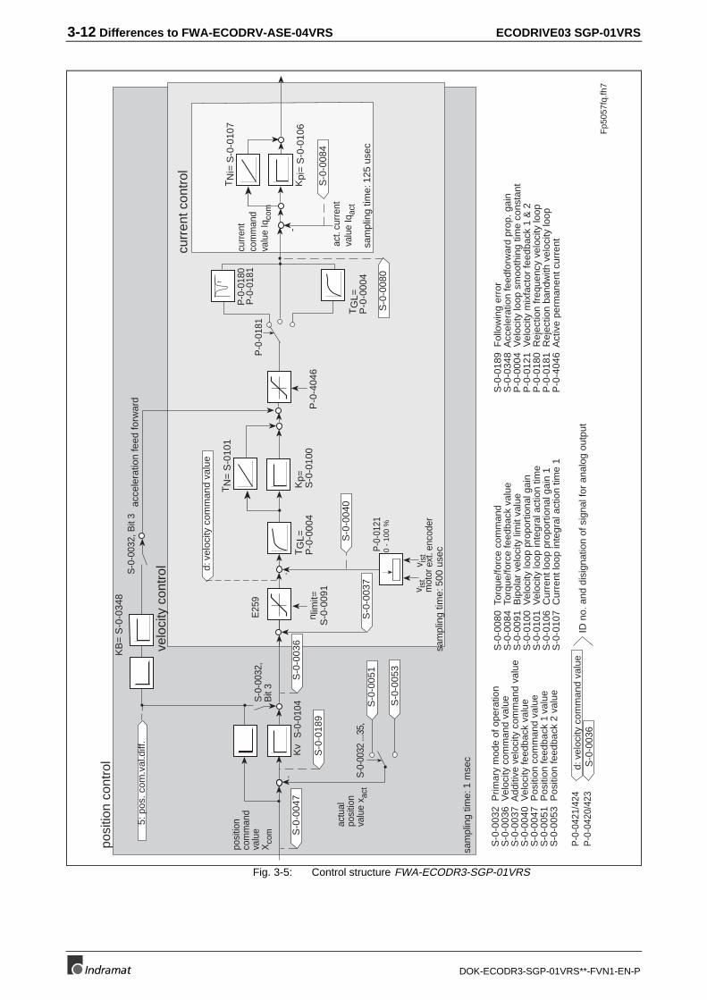
Controller StructureThe velocity controller has been modified so that
• the deep pass filter of the actual velocity value is dropped in parameterS-0-0392, Velocity feedback filter,
• the variables (torque command) generated by the velocity controllercan be filtered over a bandstop filter with programmable frequenciesand bandwidth (Parameter P-0-0180, Rejection frequency velocityloop and P-0-0181, Rejection bandwidth velocity loop new) and
• the deep pass can be set via P-0-0004, Velocity loop smoothingtime constant to not effect the variables but rather the controldeviations of the velocity controller.
3-12 Differences to FWA-ECODRV-ASE-04VRS ECODRIVE03 SGP-01VRS
DOK-ECODR3-SGP-01VRS**-FVN1-EN-P
posi
tion
cont
rol
sam
plin
g tim
e: 1
mse
c
Fp5
057f
q.fh
7
velo
city
con
trol
sam
plin
g tim
e: 5
00 u
sec
curr
ent c
ontr
ol
-K
v
KB
= S
-0-0
348
S-0
-010
4S-0
-003
2,B
it 3
S-0
-003
2, B
it 3
-K
pi=
S-0
-010
6
TN
i= S
-0-0
107
sam
plin
g tim
e: 1
25 u
sec
S-0
-003
2 ...
35,
P-0
-018
0P
-0-0
181
S-0
-005
3
TG
L=P
-0-0
004
P-0
-018
1
f
S-0
-004
7
5: p
os. c
om.v
al.d
iff.
S-0
-003
6
S-0
-008
4S
-0-0
189
d: v
eloc
ity c
omm
and
valu
eS
-0-0
036
-
P-0
-404
6n l
imit=
S-0
-009
1
Kp=
S-0
-010
0
TN
= S
-010
1
P-0-
0121
d: v
eloc
ity c
omm
and
valu
e
TG
L=P
-0-0
004
S-0
-004
0
S-0
-008
0
S-0
-003
7
0 -
100
%
curr
ent
com
man
dva
lue
Iqco
mE
259
posi
tion
com
man
dva
lue
Xco
m
actu
alpo
sitio
nva
lue
x act
v ist
mot
orv i
stex
t. en
code
r
act.
curr
ent
valu
e Iq
act
S-0
-005
1
S-0
-003
2 P
rimar
y m
ode
of o
pera
tion
S-0
-003
6 V
eloc
ity c
omm
and
valu
eS
-0-0
037
Add
itive
vel
ocity
com
man
d va
lue
S-0
-004
0 V
eloc
ity fe
edba
ck v
alue
S-0
-004
7 P
ositi
on c
omm
and
valu
eS
-0-0
051
Pos
ition
feed
back
1 v
alue
S-0
-005
3 P
ositi
on fe
edba
ck 2
val
ue
S-0
-008
0 T
orqu
e/fo
rce
com
man
dS
-0-0
084
Tor
que/
forc
e fe
edba
ck v
alue
S-0
-009
1 B
ipol
ar v
eloc
ity li
mit
valu
eS
-0-0
100
Vel
ocity
loop
pro
port
iona
l gai
nS
-0-0
101
Vel
ocity
loop
inte
gral
act
ion
time
S-0
-010
6 C
urre
nt lo
op p
ropo
rtio
nal g
ain
1S
-0-0
107
Cur
rent
loop
inte
gral
act
ion
time
1
S-0
-018
9 F
ollo
win
g er
ror
S-0
-034
8 A
ccel
erat
ion
feed
forw
ard
prop
. gai
nP
-0-0
004
Vel
ocity
loop
sm
ooth
ing
time
cons
tant
P-0
-012
1 V
eloc
ity m
ixfa
ctor
feed
back
1 &
2P
-0-0
180
Rej
ectio
n fr
eque
ncy
velo
city
loop
P-0
-018
1 R
ejec
tion
band
with
vel
ocity
loop
P-0
-404
6 A
ctiv
e pe
rman
ent c
urre
nt
P-0
-042
1/42
4ID
no.
and
dis
igna
tion
of s
igna
l for
ana
log
outp
utP
-0-0
420/
423
acce
lera
tion
feed
forw
ard
Fig. 3-5: Control structure FWA-ECODR3-SGP-01VRS
ECODRIVE03 SGP-01VRS Differences to FWA-ECODRV-ASE-04VRS 3-13
DOK-ECODR3-SGP-01VRS**-FVN1-EN-P
Velocity Control Loop MonitoringThe velocity control loop monitor can be switched off with bit 8 ofparameter P-0-0538, Motor function parameter 1.
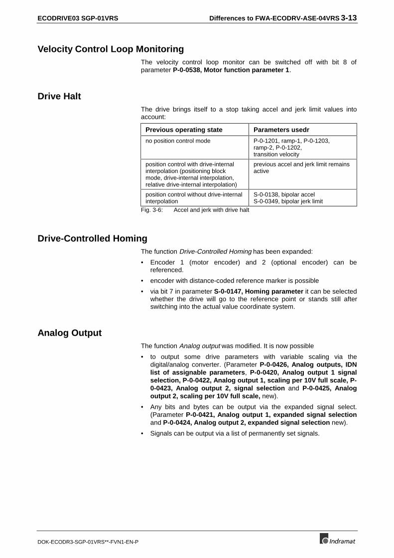
Drive HaltThe drive brings itself to a stop taking accel and jerk limit values intoaccount:
Previous operating state Parameters usedr
no position control mode P-0-1201, ramp-1, P-0-1203,ramp-2, P-0-1202,transition velocity
position control with drive-internalinterpolation (positioning blockmode, drive-internal interpolation,relative drive-internal interpolation)
previous accel and jerk limit remainsactive
position control without drive-internalinterpolation
S-0-0138, bipolar accelS-0-0349, bipolar jerk limit
Fig. 3-6: Accel and jerk with drive halt
Drive-Controlled HomingThe function Drive-Controlled Homing has been expanded:
• Encoder 1 (motor encoder) and 2 (optional encoder) can bereferenced.
• encoder with distance-coded reference marker is possible
• via bit 7 in parameter S-0-0147, Homing parameter it can be selectedwhether the drive will go to the reference point or stands still afterswitching into the actual value coordinate system.
Analog OutputThe function Analog output was modified. It is now possible
• to output some drive parameters with variable scaling via thedigital/analog converter. (Parameter P-0-0426, Analog outputs, IDNlist of assignable parameters, P-0-0420, Analog output 1 signalselection, P-0-0422, Analog output 1, scaling per 10V full scale, P-0-0423, Analog output 2, signal selection and P-0-0425, Analogoutput 2, scaling per 10V full scale, new).
• Any bits and bytes can be output via the expanded signal select.(Parameter P-0-0421, Analog output 1, expanded signal selectionand P-0-0424, Analog output 2, expanded signal selection new).
• Signals can be output via a list of permanently set signals.
3-14 Differences to FWA-ECODRV-ASE-04VRS ECODRIVE03 SGP-01VRS
DOK-ECODR3-SGP-01VRS**-FVN1-EN-P
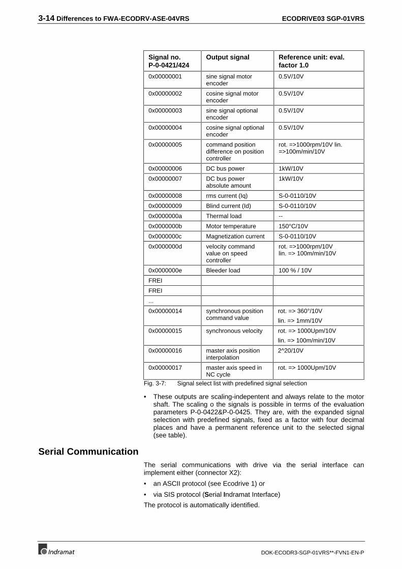
Signal no.P-0-0421/424
Output signal Reference unit: eval.factor 1.0
0x00000001 sine signal motorencoder
0.5V/10V
0x00000002 cosine signal motorencoder
0.5V/10V
0x00000003 sine signal optionalencoder
0.5V/10V
0x00000004 cosine signal optionalencoder
0.5V/10V
0x00000005 command positiondifference on positioncontroller
rot. =>1000rpm/10V lin.=>100m/min/10V
0x00000006 DC bus power 1kW/10V
0x00000007 DC bus powerabsolute amount
1kW/10V
0x00000008 rms current (Iq) S-0-0110/10V
0x00000009 Blind current (Id) S-0-0110/10V
0x0000000a Thermal load --
0x0000000b Motor temperature 150°C/10V
0x0000000c Magnetization current S-0-0110/10V
0x0000000d velocity commandvalue on speedcontroller
rot. =>1000rpm/10Vlin. => 100m/min/10V
0x0000000e Bleeder load 100 % / 10V
FREI
FREI
...
0x00000014 synchronous positioncommand value
rot. => 360°/10V
lin. => 1mm/10V
0x00000015 synchronous velocity rot. => 1000Upm/10V
lin. => 100m/min/10V
0x00000016 master axis positioninterpolation
2^20/10V
0x00000017 master axis speed inNC cycle
rot. => 1000Upm/10V
Fig. 3-7: Signal select list with predefined signal selection
• These outputs are scaling-indepentent and always relate to the motorshaft. The scaling o the signals is possible in terms of the evaluationparameters P-0-0422&P-0-0425. They are, with the expanded signalselection with predefined signals, fixed as a factor with four decimalplaces and have a permanent reference unit to the selected signal(see table).
Serial CommunicationThe serial communications with drive via the serial interface canimplement either (connector X2):
• an ASCII protocol (see Ecodrive 1) or
• via SIS protocol (Serial Indramat Interface)
The protocol is automatically identified.

ECODRIVE03 SGP-01VRS Differences to FWA-DIAX-ELS-05VRS 4-1
DOK-ECODR3-SGP-01VRS**-FVN1-EN-P
4 Differences to FWA-DIAX-ELS-05VRS
4.1 New Functions
Multiplex ChannelUsing this channel it is possible to expan the limited cyclical data channel.It enables a cyclical accessing of list elements by index switching.
The following parameters are used here:
• S-0-0360, MDT Data container A
• S-0-0362, List index, MDT data container A
• S-0-0364, AT Data container A
• S-0-0366, List index, AT data container A
• S-0-0368, Addressing for data container A
• S-0-0370, Configuration list for MDT data container
• S-0-0371, Configuration list for the AT data container
Analog Command CommunicationsVelocity and torque command values are set using the analog inputs.Digital inputs are available to activate the controller. If SERCOScommunications is not active at the point in time when the control voltageis switched on then the drive can be operated with the analog commandcommunication option.
Parallel Command CommunicationThe parallel interfaces makes ten (10) frely configurable inputs and ten(10) outputs available.
Firmware LoaderA firmware loader can be used to load the firmware onto the programmingmodule. The module does not have to be replaced to conduct an update.
Operating ModesThe following modes are used:
Positioning block modeIn this mode up to 64 programmed blocks can be run off. The drive runsin position control to the target position while maintaining the velocity,acceleration and jerk limits defined by the block.
• P-0-4006, Process block target position
• P-0-4007, Process block velocity
• P-0-4008, Process block acceleration
• P-0-4009, Process block jerk
• P-0-4019, Process block mode
• P-0-4026, Process block selection
• P-0-4051, Process block acquittance
• P-0-4052, Positioning block, last accepted
Pertinent parameters

4-2 Differences to FWA-DIAX-ELS-05VRS ECODRIVE03 SGP-01VRS
DOK-ECODR3-SGP-01VRS**-FVN1-EN-P
• P-0-4057, Positioning block, input linked blocks
• P-0-4060, Process block control word
• S-0-0346, Setup flag for relative command values
• S-0-0182, Manufacturer class 3 diagnostics
• S-0-0259, Positioning Velocity
Operating Mode Step-Motor OperationIn "Step motor mode"" the drive behaves like a conventional step motordrive. Conventional step motor controls can be used to control the drive inthis case.
This mode is only available in conjunction with a parallel interface which isthe reason why it is only used with the DKC01.3.
• P-0-4033, Stepper motor resolution
• P-0-4034, Stepper motor interface mode
• P-0-0099, Position command smoothing time constant
Jogging ModeThis mode is used to "manually" run an axis.
Jog input switches to move the axes can be mounted to units equippedwith positioning interface or step motor interface.
• P-0-4030, Jog velocity
• P-0-4056, Jog inputs
• S-0-0260, Positioning Acceleration
• S-0-0193, Positioning Jerk
Velocity synchronization mode with real master axisThe drive synchronizes to a master axis position (real) gained from amaster axis encoder.
Encoder 2 evaluates the master axis encoder.
(See section: "Master axis encoder").
Electronic cam with real master axis modeSee "Electronic cam with real master axis" in section: "Differences toFWA-ECODR3-SMT-01VRS".
Automatic Control Loop SettingsTo make it easier to parametrize the drive, the firmware offers anautomatic control loop setting. The results can be influenced viaparameter P-0-0163, Damping factor for autom. control loop adjustand P-0-0164, Application for autom. control loop adjust, (Controlloop dynamics).
Pertinent parameters
Pertinent parameters

ECODRIVE03 SGP-01VRS Differences to FWA-DIAX-ELS-05VRS 4-3
DOK-ECODR3-SGP-01VRS**-FVN1-EN-P
Configurable Signal Control WordThe signal control word offers the option to overwrite individual controlwords scattered over various parameters into one configurablecollective parameter.
With the configurable signal control word, up to 16 copies can be made ofbits in other drive parameters.
This mechanism can be used, e.g., with
• position block mode via parallel interface or
• main spindle mode via parallel interface.
The following parameters are used for the function:
• S-0-0027, Configuration list signal control word
• S-0-0329, Assign list signal control word
• S-0-0145, Signal control word
• S-0-0399, IDN list of configurable data in the signal control word
4.2 Changed Functions
PL displayed when switching on the control voltageIf PL is displayed after the control voltage is switched on, then firmwareversion has been replaced and the drive wants to overwrite all parameterswith the basic parameters. The base parameters can only be loaded bypresing the S1 key. It is not possible to communicate with the drive forthis entire length of time.
PasswordThose parameters protected by the user’s password are entered inparameter S-0-0279, IDN-list of password-protected operation data.
List of Diagnostic NumbersThe 50 previously displayed diagnostic numbers are stored in parameterS-0-0375, List of diagnostic numbers in chronological order. Each timethe contents of S-0-0390, Diagnostic message number are changed,the contents of S-0-0375, List of diagnostic numbers are assumed. IfS-0-0375, List of diagnostic numbers is read, then the previousdiagnostic number appears in the first element; the first element appearsin the second and so on.
Permanently Configured Status Messages
• End position reached,
• ready and
• warning
have been added to parameter S-0-0182, Manufacturer class 3diagnostics.
Application

4-4 Differences to FWA-DIAX-ELS-05VRS ECODRIVE03 SGP-01VRS
DOK-ECODR3-SGP-01VRS**-FVN1-EN-P
Compatibility Class CSERCOS compatibility class C has been added.
Motor Holding BrakeThe motor holding brake current is not monitored.The holding brake can be set as a servo or main spindle brake (P-0-0525,Type of motor brake Bit 1) . The brake of a servo brake is switched onafter the maximum brake time (P-0-0126, Maximum braking time) isexceeded. A main spindle brake is not activated until the actual velocity is< 10rpm or10mm/min.
Magnetization Current for Asynchronous MotorsIt is not possible to lower the magnetization currents as of the transitionspeed in asynchronous motors for the S1 mode.
Commutation SettingsThe commutation setting is only possible in kit motors (MBS) or linearmotors (LSF). The setting is performed by oscillating the motor.
Operating ModesThe following modes have been changed:
Operating Mode Torque ControlTor control mode has a command value filter. The value is filtered with aPT1 filter. The parameter to set the time constant is P-0-0176, Torquecommand value smoothing time constant.
Velocity control modeTwo command value ramps and one PT1 filter effect the velocitycommand value.
• P-0-1201, Ramp 1 pitch
• P-0-1203, Ramp 2 pitch
• P-0-1202, Final speed of ramp 1
Relative drive-internal interpolation modeWhen activating this mode, the travel path can, depending on parameterS-0-0393, Command value mode, relate to the actual position or thevalue set in parameter S-0-0258, Target position.
Measuring SystemsSee section: "Measuring Systems" in section "Differences to FWA-ECODRV-ASE-04VRS"
Evaluating an Absolute Measuring SystemParameter S-0-0378, Encoder 1, absolute range defines the area inwhich the position data of encoder 1 can be absolutely generated.Parameter S-0-0379, Encoder 2, absolute range defines the area inwhich the position data of encoder 2 can be absolutely generated.

ECODRIVE03 SGP-01VRS Differences to FWA-DIAX-ELS-05VRS 4-5
DOK-ECODR3-SGP-01VRS**-FVN1-EN-P
Travel Range MonitoringThe state of the travel range limit switch is displayed in parameter P-0-0222, State of Travel range limit inputs.
Master axis encoderIn addition to single or multiturn encoders, incremental encoders are alsopossible. This includes automatic detection of zero pulse followed bytransition from P-0-0052 to the offset P-0-0087. Actual position value 3 issmoothed via PT1 filter, the time constant is set in parameter P-0-0186,Actual Position value 3, smoothing time.
E-stop FunctionThe state of the E-stop input is shown in parameter P-0-0223, StatusInput E-Stop function.
Load Base ValuesThe command can be conducted with drive enable applied.
A comparison between parameter motor type in feedback memory (S-7-0141) and parameter motor type in parameter memory (S-0-0141)generates the diagnosis "UL motor type has changed“.
Velocity Control Loop Monitor with Off CapabilitiesThe monitor can be switched off with parameter P-0-0538, Motorfunction parameter 1 Bit 8.
Drive HaltDepending on the current mode, drive halt is conduct variously.
Operating modes with internal interpolation set still in position controlusing the last active accel and jerk.
The values set in the followoing parameters are used to set still:
S-0-0138, Bipolar acceleration limit value
S-0-0349, Jerk limit bipolar
The following parameters are used to set still when in velocity and torquecontrol:
P-0-1201, Ramp 1 pitch
P-0-1202, Final speed of ramp 1
P-0-1203, Ramp 2 pitch
P-0-1222, Velocity command filter
Drive-Controlled HomingThe drive runs to the reference point with the absolute encoder alreadyreferenced if bit 7 = 1 has been set in parameter S-0-0148, C600 Drivecontrolled homing procedure command.

4-6 Differences to FWA-DIAX-ELS-05VRS ECODRIVE03 SGP-01VRS
DOK-ECODR3-SGP-01VRS**-FVN1-EN-P
Probe Input FeatureMeasuring signal actual positions values 1 and 2, internal time, masteraxis position and actual position value 3 generate measuring valuedifferences.
Windows for actual position values, master axis position and actualposition value 3 have been implemented.
Programmable Limit SwitchThe dynamic cam switch group has 16 cams at its disposal with one camcomputed per millisecond.
Encoder EmulationEncoder emulatoin and signal select for the emulation are set inparameter P-0-4020, Encoder emulation type.
Command Measuring Wheel ModeThe command can also be started without the drive being in positioncontrol. The measuring wheel encoder position will be correctly detected.Encoder 1 checks the controls. As soon as position control has beenactivated, the measuring wheel position is run to.
Serial CommunicationSerial communiations SIS protocol possible. Communications using theserial interface is possible with the ASCII or SIS protocols. The driveautomatically detects which is set.
4.3 Functions Not Implemented
• Electrical pattern control
• Universal digital I/OsOnly the outputs read and warning can be freely allocated with thesignal status word.
ECODRIVE03 SGP-01VRS Kundenbetreuungstellen - Sales & Service Facilities
DOK-ECODR3-SGP-01VRS**-FVN1-EN-P
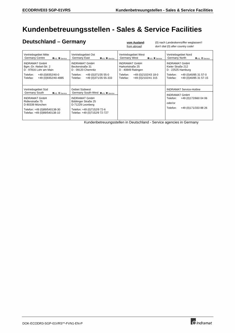
Kundenbetreuungsstellen - Sales & Service Facilities
Deutschland – Germany vom Ausland: (0) nach Landeskennziffer weglassen!!from abroad: don’t dial (0) after country code!
Vertriebsgebiet Mitte Germany Centre V/S Service
INDRAMAT GmbHBgm.-Dr.-Nebel-Str. 2D - 97816 Lohr am Main
Telefon: +49 (0)9352/40-0Telefax: +49 (0)9352/40-4885
Vertriebsgebiet Ost Germany East V/S Service
INDRAMAT GmbHBeckerstraße 31D - 09120 Chemnitz
Telefon: +49 (0)371/35 55-0Telefax: +49 (0)371/35 55-333
Vertriebsgebiet West Germany West V/S Service
INDRAMAT GmbHHarkortstraße 25D - 40849 Ratingen
Telefon: +49 (0)2102/43 18-0Telefax: +49 (0)2102/41 315
Vertriebsgebiet Nord Germany North V/S Service
INDRAMAT GmbHKieler Straße 212D - 22525 Hamburg
Telefon: +49 (0)40/85 31 57-0Telefax: +49 (0)40/85 31 57-15
Vertriebsgebiet Süd Germany South V/S Service
INDRAMAT GmbHRidlerstraße 75D-80339 München
Telefon: +49 (0)89/540138-30Telefax: +49 (0)89/540138-10
Gebiet Südwest Germany South-West V/S Service
INDRAMAT GmbHBöblinger Straße 25D-71229 Leonberg
Telefon: +49 (0)7152/9 72-6Telefax: +49 (0)7152/9 72-727
INDRAMAT Service-Hotline
INDRAMAT GmbHTelefon: +49 (0)172/660 04 06
oder/or
Telefon: +49 (0)171/333 88 26
Kundenbetreuungsstellen in Deutschland - Service agencies in Germany

Kundenbetreuungstellen - Sales & Service Facilities ECODRIVE03 SGP-01VRS
DOK-ECODR3-SGP-01VRS**-FVN1-EN-P
Europa – Europe vom Ausland: (0) nach Landeskennziffer weglassen, 0 nach Landeskennziffer mitwählen!from abroad: don’t dial (0) after country code, dial 0 after country code!
Austria V/S Service
Mannesmann Rexroth Ges.m.b.H.Geschäftsbereich INDRAMATHägelingasse 3A - 1140 Wien
Telefon: +43 (0)1/9852540-400Telefax: +43 (0)1/9852540-93
Austria V/S Service
Mannesmann Rexroth G.m.b.H.Geschäftsbereich INDRAMATIndustriepark 18A - 4061 Pasching
Telefon: +43 (0)7221/605-0Telefax: +43 (0)7221/605-21
Belgium V/S Service
Mannesmann Rexroth N.V.-S.A.Geschäftsbereich INDRAMATIndustrielaan 8B-1740 Ternat
Telefon: +32 (0)2/5823180Telefax: +32 (0)2/5824310
Denmark V/S Service
BEC ASZinkvej 6DK-8900 Randers
Telefon: +45 (0)87/11 90 60Telefax: +45 (0)87/11 90 61
England V/S Service
Mannesmann Rexroth Ltd.INDRAMAT Division4 Esland Place, Love LaneGB - Cirencester, Glos GL7 1YG
Telefon: +44 (0)1285/658671Telefax: +44 (0)1285/654991
Finland V/S Service
Rexroth Mecman OYAnsatie 6SF-017 40 Vantaa
Telefon: +358 (0)9/84 91 11Telefax: +358 (0)9/84 91 13 60
France V/S Service
Mannesmann Rexroth S.A.Division INDRAMATParc des Barbanniers4, Place du VillageF-92632 Gennevilliers Cedex
Telefon: +33 (0)141 47 54 30Telefax: +33 (0)147 94 69 41Hotline: +33 (0)6 08 33 43 28
France V/S Service
Mannesmann Rexroth S.A.Division INDRAMAT270, Avenue de LardenneF - 31100 Toulouse
Telefon: +33 (0)5 61 49 95 19Telefax: +33 (0)5 61 31 00 41
France V/S Service
Mannesmann Rexroth S.A.Division INDRAMAT91, Bd. Irène Joliot-CurieF - 69634 Vénissieux - Cedex
Telefon: +33 (0)4 78 78 53 65Telefax: +33 (0)4 78 78 52 53
Italy V/S Service
Mannesmann Rexroth S.p.A.Divisione INDRAMATVia G. Di Vittoria, 1I - 20063 Cernusco S/N.MI
Telefon: +39 02/92 36 52 70Telefax: +39 02/92 36 55 12
Italy V/S Service
Mannesmann Rexroth S.p.A.Divisione INDRAMATVia Borgomanero, 11I - 10145 Torino
Telefon: +39 011/7 71 22 30Telefax: +39 011/7 71 01 90
Italy V/S Service
Mannesmann Rexroth S.p.A.Divisione INDRAMATVia del Progresso, 16 (Zona Ind.)I - 35020 Padova
Telefon: +39 049/8 70 13 70Telefax: +39 049/8 70 13 77
Italy V/S Service
Mannesmann Rexroth S.p.A.Divisione INDRAMATVia de Nicola, 12I - 80053 Castellamare di Stabbia NA
Telefon: +39 081/8 72 30 37Telefax: +39 081/8 72 30 18
Italy V/S Service
Mannesmann Rexroth S.p.A.Divisione INDRAMATViale Oriani, 38/AI - 40137 Bologna
Telefon: +39 051/34 14 14Telefax: +39 051/34 14 22
Netherlands V/S Service
Hydraudyne Hydrauliek B.V.Kruisbroeksestraat 1P.O. Box 32NL - 5281 RV Boxtel
Telefon: +31 (0)411/65 19 51Telefax: +31 (0)411/65 14 83e-mail: [email protected]
Netherlands V/S Service
Hydrocare B.V.Kruisbroeksestraat 1P.O. Box 32NL - 5281 RV Boxtel
Telefon: +31 (0)411/65 19 51Telefax: +31 (0)411/67 78 14
Poland V/S Service
Mannesmann Rexroth Sp.zo.o.Biuro Poznanul. Dabrowskiego 81/85PL – 60-529 Poznan
Telefon: +48 061/847 67 99Telefax: +48 061/847 64 02
Spain V/S Service
Mannesmann Rexroth S.A.Divisiòn INDRAMATCentro Industrial SantigaObradors s/nE-08130 Santa Perpetua de MogodaBarcelona
Telefon: +34 937 47 94 00Telefax: +34 937 47 94 01
Spain V/S Service
Goimendi S.A.División IndramatJolastokieta (Herrera)Apartado 11 37E - 20017 San Sebastian
Telefon: +34 9 43/40 01 63Telefax: +34 9 43/39 17 99
Sweden V/S Service
Rexroth Mecman Svenska ABINDRAMAT DivisionVaruvägen 7S - 125 81 Stockholm
Telefon: +46 (0)8/727 92 00Telefax: +46 (0)8/64 73 277
Switzerland - East V/S Service
Mannesmann Rexroth AGGeschäftsbereich INDRAMATGewerbestraße 3CH-8500 Frauenfeld
Telefon: +41 (0)52/720 21 00Telefax: +41 (0)52/720 21 11
Switzerland - West V/S Service
Mannesmann Rexroth SADépartement INDRAMATChemin de l`Ecole 6CH-1036 Sullens
Telefon: +41 (0)21/731 43 77Telefax: +41 (0)21/731 46 78
Russia V/S Service
Tschudnenko E.B.Arsenia 22RUS - 153000 IvanovoRußland
Telefon: +7 093/223 96 33oder/or +7 093/223 95 48Telefax: +7 093/223 46 01
Slowenia V/S Service
INDRAMAT elektromotorji d.o.o.Otoki 21SLO - 64 228 Zelezniki
Telefon: +386 64/61 73 32Telefax: +386 64/64 71 50
Turkey V/S Service
Mannesmann Rexroth Hidropar A..S.Fevzi Cakmak Cad No. 3TR - 34630 Sefaköy Istanbul
Telefon: +90 212/541 60 70Telefax: +90 212/599 34 07
Europäische Kundenbetreuungsstellen (ohne Deutschland)European Service agencies (without Germany)
ECODRIVE03 SGP-01VRS Kundenbetreuungstellen - Sales & Service Facilities
DOK-ECODR3-SGP-01VRS**-FVN1-EN-P
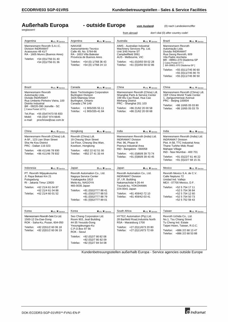
Außerhalb Europa - outside Europe vom Ausland: (0) nach Landeskennzifferweglassen!
from abroad: don’t dial (0) after country code!
Argentina V/S Service
Mannesmann Rexroth S.A.I.C.Division INDRAMATAcassusso 48 41/7RA - 1605 Munro (Buenos Aires)
Telefon: +54 (0)1/756 01 40+54 (0)1/756 01 36
Argentina V/S Service
NAKASEAsesoramiento TecnicoCalle 49, No. 5764-66RA - 1653 Villa BalesterProvincia de Buenos Aires
Telefon: +54 (0) 1/768 36 43Telefax: +54 (0) 1/768 24 13
Australia V/S Service
AIMS - Australian IndustrialMachinery Services Pty. Ltd.Unit 3/45 Horne STCampbellfield 3061AUS - Melbourne, VIC
Telefon: +61 (0)3/93 59 02 28Telefax: +61 (0)3/93 59 02 86
Brazil V/S Service
Mannesmann RexrothAutomação Ltda.Divisão INDRAMATRua Georg Rexroth, 609Vila Padre AnchietaBR - 09951-270 Diadema-SP[ Caixa Postal 377 ][ BR-09901-970 Diadema-SP ]
Telefon: +55 (0)11/745 90 60+55 (0)11/745 90 70
Telefax: +55 (0)11/745 90 50
Brazil V/S Service
Mannesmann RexrothAutomação Ltda.Divisão INDRAMATRua Umberto Pinheiro Vieira, 100Distrito IndustrialBR - 09220-390 Joinville - SC[ Caixa Postal 1273 ]
Tel./Fax: +55 (0)47/473 55 833Mobil: +55 (0)47 974 6645e-mail: [email protected]
Canada V/S Service
Basic Technologies CorporationBurlington Division3426 Mainway DriveBurlington, OntarioCanada L7M 1A8
Telefon: +1 905/335 55 11Telefax: +1 905/335-41 84
China V/S Service
Mannesmann Rexroth (China) Ldt.Shanghai Parts & Service Center199 Wu Cao Road, Hua CaoMinhang DistrictPRC - Shanghai 201 103
Telefon: +86 21/62 20 00 58Telefax: +86 21/62 20 00 68
China V/S Service
Mannesmann Rexroth (China) Ldt.15/F China World Trade Center1, Jianguomenwai AvenuePRC - Beijing 100004
Telefon: +86 10/65 05 03 80Telefax: +86 10/65 05 03 79
China V/S Service
Mannesmann Rexroth (China) Ldt.A-5F., 123 Lian Shan StreetSha He Kou DistrictPRC - Dalian 116 023
Telefon: +86 411/46 78 930Telefax: +86 411/46 78 932
Hongkong V/S Service
Rexroth (China) Ldt.19 Cheung Shun Street1st Floor, Cheung Sha Wan,Kowloon, Hongkong
Telefon: +852 22 62 51 00Telefax: +852 27 41 33 44
India V/S Service
Mannesmann Rexroth (India) Ltd.INDRAMAT DivisionPlot. 96, Phase IIIPeenya Industrial AreaIND - Bangalore - 560058
Telefon: +91 (0)80/8 39 73 74Telefax: +91 (0)80/8 39 43 45
India V/S Service
Mannesmann Rexroth (India) Ltd.INDRAMAT DivisionPlot. A-58, TTC Industrial AreaThane Turbhe Midc RoadMahape VillageIND - Navi Mumbai - 400 701
Telefon: +91 (0)22/7 61 46 22Telefax: +91 (0)22/7 68 15 31
Indonesia V/S Service
PT. Rexroth WijayakusumaJl. Raya Bekasi Km 21PulogadungRI - Jakarta Timur 13920
Telefon: +62 21/4 61 04 87+62 21/4 61 04 88
Telefax: +62 21/4 60 01 52
Japan V/S Service
Rexroth Automation Co., Ltd.Nagoya Service CenterYutakagaoka 1810Meito-ku, NAGOYA465-0035 Japan
Telefon: +81 (0)52/777 88 41+81 (0)52/777 88 53+81 (0)52/777 88 79
Telefax: +81 (0)52/777 89 01
Japan V/S Service
Rexroth Automation Co., Ltd.INDRAMAT Division1F, I.R. BuildingNakamachidai 4-26-44Tsuzuki-ku, YOKOHAMA224-0041 Japan
Telefon: +81 459/42-72 10Telefax: +81 459/42-03 41
Mexico V/S Service
Rexroth Mexico S.A. de C.V.Calle Neptuno 72Unidad Ind. VallejoMEX - 07700 Mexico, D.F.
Telefon: +52 5 754 17 11+52 5 754 36 84+52 5 754 12 60
Telefax: +52 5 754 50 73+52 5 752 59 43
Korea V/S Service
Mannesmann Rexroth-Seki Co Ltd.1500-12 Da-Dae-DongROK - Saha-Ku, Pusan, 604-050
Telefon: +82 (0)51/2 60 06 18Telefax: +82 (0)51/2 60 06 19
Korea V/S Service
Seo Chang Corporation Ltd.Room 903, Jeail Building44-35 Yeouido-DongYeoungdeungpo-KuC.P.O.Box 97 56ROK - Seoul
Telefon: +82 (0)2/7 80 82 08+82 (0)2/7 80 82 09
Telefax: +82 (0)2/7 84 54 08
South Africa V/S Service
HYTEC Automation (Pty) Ltd.28 Banfield Road,Industria NorthRSA - Maraisburg 1700
Telefon: +27 (0)11/673 20 80Telefax: +27 (0)11/673 72 69
Taiwan V/S Service
Rexroth Uchida Co., Ltd.No.1, Tsu Chiang StreetTu Cheng Ind. EstateTaipei Hsien, Taiwan, R.O.C.
Telefon: +886 2/2 68 13 47Telefax: +886 2/2 68 53 88
Kundenbetreuungsstellen außerhalb Europa - Service agencies outside Europe

Kundenbetreuungstellen - Sales & Service Facilities ECODRIVE03 SGP-01VRS
DOK-ECODR3-SGP-01VRS**-FVN1-EN-P
Außerhalb Europa / USA - outside Europe / USA
USA V/S Service
Mannesmann Rexroth CorporationINDRAMAT Division5150 Prairie Stone ParkwayUSA -Hoffman Estates, IL 60192-3707
Telefon: +1 847/6 45 36 00Telefax: +1 847/6 45 62 01
USA V/S Service
Mannesmann Rexroth CorporationINDRAMAT DivisionCentral Region Technical CenterUSA - Auburn Hills, MI 48326
Telefon: +1 248/3 93 33 30Telefax: +1 248/3 93 29 06
USA V/S Service
Mannesmann Rexroth CorporationINDRAMAT DivisionSoutheastern Technical Center3625 Swiftwater Park DriveUSA - SuwaneeGeorgia 30174
Telefon: +1 770/9 32 32 00+1 770/9 32 19 03
USA V/S Service
Mannesmann Rexroth CorporationINDRAMAT DivisionNortheastern Technical Center99 Rainbow RoadUSA - East Granby,Connecticut 06026
Telefon: +1 860/8 44 83 77+1 860/8 44 85 95
USA V/S Service
Mannesmann Rexroth CorporationINDRAMAT DivisionCharlotte Regional Sales Office14001 South Lakes DriveUSA - Charlotte,North Carolina 28273
Telefon: +1 704/5 83 97 62+1 704/5 83 14 86
Kundenbetreuungsstellen außerhalb Europa / USA Service agencies outside Europe / USA

ECODRIVE03 SGP-01VRS Differences to FWA-DIAX-ELS-05VRS
DOK-ECODR3-SGP-01VRS**-FVN1-EN-P
Notes

Indramat