EcoBot IV: A Robotic Energy Harvester - H2FCSUPERGEN · aIeropoulos, Ioannis A., Greenman, John and...
15
EcoBot IV : A Robotic Energy Harvester I. Ieropoulos, G. Papaharalabos, A. Stinchcombe, J. Greenman, C. Melhuish.
-
Upload
trinhquynh -
Category
Documents
-
view
217 -
download
0
Transcript of EcoBot IV: A Robotic Energy Harvester - H2FCSUPERGEN · aIeropoulos, Ioannis A., Greenman, John and...

EcoBot IV: A Robotic Energy Harvester I. Ieropoulos, G. Papaharalabos, A. Stinchcombe, J. Greenman, C. Melhuish.

Microbial Fuel Cell Principle
“The disintegration of organic compounds
by microorganisms is accompanied by the
liberation of electrical energy"
-M.C.Potter, 1911

Smaller is better*
*Ieropoulos I, Greenman J, Melhuish C. Microbial fuel cells based on carbon veil electrodes: stack configuration and scalability. Int J Energy Res (2008b), 32:1228–40
6.25 mL 25 mL
500 mL

Chamber size↘ Internal resistance ↘
Higher substrate utilisation (low mass
transfer losses)
Short H+ travel distance from anode to
cathode
Lower Activation losses
Increased Surface to Volume ratio
Porous electrode's resistivity (ρ) decreases
with smaller lengths of electrode material
*Ieropoulos I, Melhuish C, Greenman J, Horsfield I. EcoBot-III: a robot with guts. Proc. of the Alife XII Conference, Odense, Denmark, (2010)
6.25 mL*

Safety in numbers
48 MFC stack* 300 ml total volume (48 x 6.25 mL)
~12.8 Volts
1.5 mW
Each MFC 5mW/m2
• Higher voltage & current output from small stacked units compared to 1 MFC unit of the overall same volume.
• Variety of electrical connections
Matching different voltage and current demands.
*Ieropoulos, Ioannis A., Greenman, John and Melhuish Chris (2013) "Miniature microbial fuel cells and stacks for urine utilisation", International Journal of Hydrogen Energy, Volume 38, Issue 1, 11 January 2013, pp492-496, In Press Science Direct 0360-3199

1. Ieropoulos I, Greenman J, Melhuish C. Imitating Metabolism: Energy Autonomy in Biologically Inspired Robots. Proceedings of the AISB '03, Second International Symposium on Imitation in Animals and Artifacts, Aberystwyth, Wales, (2003), 191-94. 2. Ieropoulos I, Melhuish C, Greenman J, Horsfield I. EcoBot-II: An artificial agent with a natural metabolism. Int J Advanced Robotic Systems. (2006), 2, 295-00 3. Ieropoulos I, Melhuish C, Greenman J, Horsfield I. EcoBot-III: a robot with guts. Proc. of the Alife XII Conference, Odense, Denmark, (2010).

EcoBot- I
EcoBot- II
EcoBot- III

EcoBot IV A next gen energy harvesting platform
aIeropoulos, Ioannis A., Greenman, John and Melhuish Chris (2013) "Miniature microbial fuel cells and stacks for urine utilisation", International Journal of Hydrogen Energy, Volume 38, Issue 1, 11 January 2013, pp492-496, In Press Science Direct 0360-3199. bG. Papaharalabos, J. Greenman, C. Melhuish, C. Santoro, P. Cristiani, B. Li, I. Ieropoulos, Increased power output from micro porous layer (MPL) cathode microbial fuel cells (MFC), International Journal of Hydrogen Energy, Volume 38, Issue 26, 30 August 2013, Pages 11552-11558.
•48 MFCs on EcoBot-III. •1.5 mW stack power (5mW/m2 from each unit)a
•2 tier cascade feedstock distribution RINT heterogeneity between MFC units.
•0.8F electrolytic capacitors
EcoBot-III • 24 MFCs with improved cathode
materials. • 1.8 mW stack power (15mW/m2 from
each unitb). • Equal feedstock distribution similar
RINT in each MFC unit. • 1.5 Farad electrical double layer
supercapacitors
EcoBot-IV

EcoBot IV technical specs
• Operating voltage between 2.0 V and 2.97 V, depending on the actuation (i.e. a voltage differential between 0.8 – 1V).
• Charging times from the lower threshold of 2.0V to the upper limit of 2.97 V can vary due to:
1. Biofilm maturity. 2. RINT. 3. T oC . 4. pH. 5. Concentration of organic matter in the anolyte. 6. Hydration of the cathode. 7. O2 diffusion on the cathode. 8. Electrical configuration of the stack.
Plan view of EcoBot IV

EcoBot IV technical specs
• Electrical configuration of the stack was 3 MFCs in parallel, and the
resulting 8 groups of these MFCs, in series.
• VOC of 4.8 Volts and 600μA (under load)
• Charging of supercapacitors (1.5 F) in less than 40 minutes and
actuating for 20 seconds.
Moving gantry mechanism for synchronous feeding

EcoBot IV features
• Individual voltage monitoring of MFCs.
• Telemetry data transmission via a two-way wireless communication link.
• Feedback to the user about the ‘health’ status of the MFCs.
• Manual reconfiguration of the electrical connections within the MFC stack matching current or voltage requirements, depending on the level of energy under different conditions
EcoBot-IV maintains the artificial stomach for predigestion and recirculation of nutrients. A peristaltic pump is also present for excreting waste.
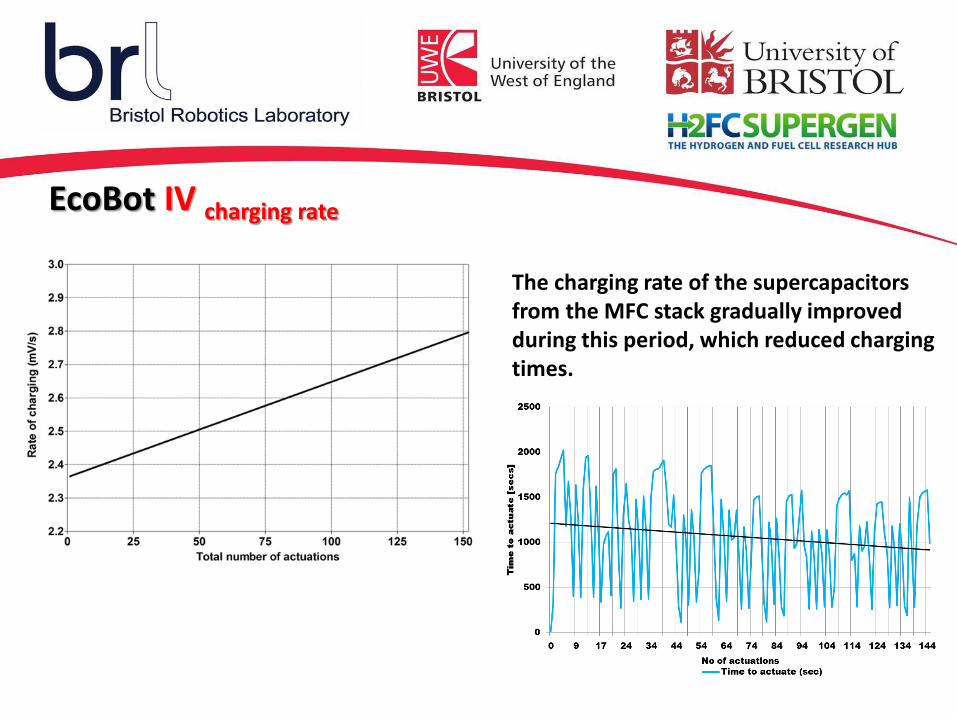
EcoBot IV charging rate
The charging rate of the supercapacitors from the MFC stack gradually improved during this period, which reduced charging times.

EcoBot IV improving performance
The smaller number of MFCs on the
EcoBot-IV platform continued to
improve their performance through
time, which was depended on the
frequency of feeding and amount of
substrate they were supplied with.
0
0.5
1
1.5
2
2.5
0 7 15 23 30 38 45 53 61 68 76 83 91 98 106 113
Po
we
r (m
W)
Time (h)
Power line during 5 days

EcoBot IV
Electronics Engineers Ian Horsfield Andrew Stinchcombe Design Engineer Sam Coupland
Project leaders Dr Ioannis Ieropoulos Prof John Greenman Prof Chris Melhuish

EcoBot I & EcoBot II University of West of England and Shell UK
EPSRC GR/S80448/01 (01/04/2004 - 30/09/2005) EPSRC EP/D027403/1 (01/10/2005 - 31/01/2007)
EcoBot III & EcoBot IV EU IP (Integrated Project) "ICEA", "Integrating Cognition, Emotion and Autonomy", Grant number: EU FP-6, IST 027819