Eco Kyuon -- Microperforated Sound Absorbing Panel rainwater intrusion or dispersion of the fiber...
6
"Eco Kyuon" -- Microperforated Sound Absorbing Panel Ichiro YAMAGIWA *1 , Masaji HORIO *2 , Shigeharu NAKAOKA *2 , Takahiro YAMADA *2 *1 Mechanical Engineering Research Laboratory, Technical Development Group *2 Engineering Department, SHINKO KENZAI LTD. This paper presents the development of sound absorbing panels utilizing the sound absorption mechanism of microperforated plates and foils. Microperforated plates and foils reduce acoustic energy by generating friction damping and pressure loss from the vibration of acoustically resonating aperture air. Applying this principle, we have developed a method to predictively calculate the sound absorption coefficient and applied it to develop microperforated sound absorbing panel products. A distinct advantage of this method is that these products can be designed with the optimum frequency characteristics for the desired sound absorption coefficient. These products were used to develop rail and road noise barriers that contribute to traffic noise reduction. An additional purpose of the study was to develop a transparent sound absorbing panel solution. We selected polycarbonate, a clear polymer material, as the film material to which this technology was applied. The challenge was to overcome the drop in sound absorption due to the propensity of the transparent polymer film to intense vibrations. Improved sound absorption performance was successfully achieved by creating several combinations of manufacturable materials, calculations for predicting the sound absorption coefficient and performance verification experiments. Optimization of design elements such as sheet thickness, aperture diameter, and aperture ratio was also critical to achieving the desired performance. Since successful commercial transparent sound absorbing panels are rare, these products hold much promise for broad application in a variety of markets. Introduction Fibrous sound-absorbing materials are common in acoustic panels that are used for road and rail noise absorption applications. Some fibrous absorbers require weatherproofing with a lining of a thin polyvinyl fluoride (or similar material) film to prevent rainwater intrusion or dispersion of the fiber material. Such fibrous absorbers have presented weather resistance and disposal problems and have caused health-related problems stemming from the dispersion of fiber particles due to time-related degradation or damage to the liner. To address these problems, we have developed Eco Kyuon TM note 1) , a sound absorbing panel comprising a thin microperforated aluminum plate and multiple internal air spaces separated by microperforated aluminum foils. We have also developed a transparent sound absorbing panel by substituting the thin microperforated aluminum plate and foil with suitable transparent materials that achieve both transparency and sound absorption performance. We also resolved the panel vibration problem. Our solution to the challenge of reducing panel vibration achieved improved sound absorbing performance and enabled us to develop Eco Kyuon Clear TM note 2), 1), 2) , a transparent sound absorbing panel. 1. Performance of thin microperforated aluminum plates 1.1 Principles of sound absorption by microperforated plates This section presents the principles of sound absorption by microperforated plates. As illustrated in Fig. 1, the sound absorbing panel is a multilayered structure of perforated plates and air spaces. Fig. 2 Fig. 1 Example sound absorbing panel structure Sound insulation Micro-perforated aluminum foil Air space Perforated faceplate Absorber note 1) Eco Kyuon is the translation of a registered Japanese trademark "エコキューオン" (No.5129527) of SHINKO KENZAI LTD. note 2) Eco Kyuon Clear is the translation of a registered Japanese trademark "エコキューオンクリア" (No. 5481495) of SHINKO KENZAI LTD. Fig. 2 Principles of sound absorption Sound wave Micro-perforated plate Air mass in aperture Air space (Enclosed space) Violent vibration caused by resonance Damping due to friction with aperture wall = Sound absorption KOBELCO TECHNOLOGY REVIEW NO. 34 MAR. 2016 32
Transcript of Eco Kyuon -- Microperforated Sound Absorbing Panel rainwater intrusion or dispersion of the fiber...
"Eco Kyuon" -- Microperforated Sound Absorbing PanelIchiro YAMAGIWA*1, Masaji HORIO*2, Shigeharu NAKAOKA*2, Takahiro YAMADA*2 *1 Mechanical Engineering Research Laboratory, Technical Development Group*2 Engineering Department, SHINKO KENZAI LTD.
This paper presents the development of sound absorbing panels utilizing the sound absorption mechanism of microperforated plates and foils. Microperforated plates and foils reduce acoustic energy by generating friction damping and pressure loss from the vibration of acoustically resonating aperture air. Applying this principle, we have developed a method to predictively calculate the sound absorption coefficient and applied it to develop microperforated sound absorbing panel products. A distinct advantage of this method is that these products can be designed with the optimum frequency characteristics for the desired sound absorption coefficient. These products were used to develop rail and road noise barriers that contribute to traffic noise reduction. An additional purpose of the study was to develop a transparent sound absorbing panel solution. We selected polycarbonate, a clear polymer material, as the film material to which this technology was applied. The challenge was to overcome the drop in sound absorption due to the propensity of the transparent polymer film to intense vibrations. Improved sound absorption performance was successfully achieved by creating several combinations of manufacturable materials, calculations for predicting the sound absorption coefficient and performance verification experiments. Optimization of design elements such as sheet thickness, aperture diameter, and aperture ratio was also critical to achieving the desired performance. Since successful commercial transparent sound absorbing panels are rare, these products hold much promise for broad application in a variety of markets.
Introduction
Fibrous sound-absorbing materials are common in acoustic panels that are used for road and rail noise absorption applications. Some fibrous absorbers require weatherproofing with a lining of a thin polyvinyl fluoride (or similar material) film to prevent rainwater intrusion or dispersion of the fiber material. Such fibrous absorbers have presented weather resistance and disposal problems and have caused health-related problems stemming from the dispersion of fiber particles due to time-related degradation or damage to the liner. To address these problems, we have developed Eco KyuonTM note 1), a sound absorbing panel comprising a thin microperforated aluminum
plate and multiple internal air spaces separated by microperforated aluminum foils. We have also developed a transparent sound absorbing panel by substituting the thin microperforated aluminum plate and foil with suitable transparent materials that achieve both transparency and sound absorption performance. We also resolved the panel vibration problem. Our solution to the challenge of reducing panel vibration achieved improved sound absorbing performance and enabled us to develop Eco Kyuon ClearTM note 2), 1), 2), a transparent sound absorbing panel.
1. Performance of thin microperforated aluminum plates
1.1 Principles of sound absorption by microperforated plates
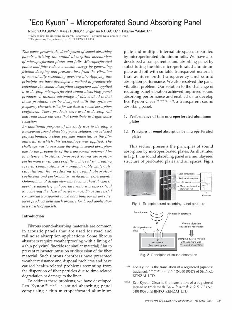
This section presents the principles of sound absorption by microperforated plates. As illustrated in Fig. 1, the sound absorbing panel is a multilayered structure of perforated plates and air spaces. Fig. 2
Fig. 1 Example sound absorbing panel structure
Sound insulation
Micro-perforatedaluminum foil
Air space
Perforated faceplate
Absorber
note 1) Eco Kyuon is the translation of a registered Japanese trademark "エコキューオン" (No.5129527) of SHINKO KENZAI LTD.
note 2) Eco Kyuon Clear is the translation of a registered Japanese trademark "エコキューオンクリア" (No. 5481495) of SHINKO KENZAI LTD.
Fig. 2 Principles of sound absorption
Sound wave
Micro-perforatedplate
Air mass in aperture
Air space(Enclosed space)
Violent vibrationcaused by resonance
Damping due to frictionwith aperture wall = Sound absorption
KOBELCO TECHNOLOGY REVIEW NO. 34 MAR. 2016 32

diagrams the principle of sound absorption with an enlarged view of an aperture in a perforated plate and an air space. The basic principle is that of a Helmholtz resonator, in which the air in the aperture of the perforated plate and the air in the space act as an acoustic mass-spring resonance system. The friction generated from the viscous damping that occurs between the air in the aperture and the aperture periphery during acoustic resonance leads to sound absorption. In essence, noise is absorbed when acoustic energy is converted via friction into heat energy. Although conventional sound-absorbing mechanisms comprising acoustically resonant perforated plates have been available for some time, we have achieved increased frictional damping in the apertures, improved sound absorption coefficient, and wideband sound absorption characteristics by shrinking the apertures to diameters of 1 mm or less.
1.2 Predictingthesoundabsorptioncoefficient
The sound absorption coefficient can be predicted for and designed into a soundabsorbing structure employing a microperforated plate3). Assuming a one-dimensional plane wave propagation, the Transfer Matrix Method can be used to estimate the coefficient. The relationship between the sound pressures (p1, p2) and particle velocities (u1, u2) upstream and downstream of the perforated plate depicted in Fig. 3 i s expressed by Eq. (1):
……………………………… (1)
where ω is the angular frequency, lA is the plate thickness, α is the aperture ratio, 2a is the aperture diameter, RV is the viscous resistance coefficient for the wall surface, and ρ0 is the density of air. Note that MA is the open end corrected acoustic inertance of the aperture and RA is the acoustic resistance. The underlying principle for sound absorption by a perforated plate lies in the attenuation due to the acoustic resistance generated by the friction between the aperture wall and the vibrating air in the aperture. By multiplying the transfer matrices of the perforated plate and the air space together, the normal incident sound absorption coefficient
can then be calculated from the specific acoustic impedance of the surface of the absorber structure.
1.3 Normalincidentsoundabsorptioncoefficient measurement
To measure the normal incident sound absorption coefficient of the microperforated aluminum absorber structure, we employed the two-microphone method 4), in which a thin microperforated aluminum plate is clamped between metallic rings and fastened to the inside of a tube. Fig. 4 is a basic diagram of the device and the fastened thin microperforated aluminum plate. The thickness of the perforated plate was 0.3 mm, the aperture diameter was 0.5 mm, and the air space depth was 40 mm. Fig. 5 shows the results of the absorption coefficient measurements and calculations. The calculated values and measured values matched well.
2. Development of sound absorbing panels with microperforated structures
2.1 Structure of sound absorbing panels
Sound absorbing panels with a microperforated aluminum absorber structure were used as a countermeasure against traffic noise. Fig. 6 is a diagram of the sound absorbing panel dimensions and cross section and Fig. 7 depicts the external
Fig. 3 Microperforations
1p 2p1u
2u
p1u1
1
0
Γ1α1
=p2u2
Γ1=jωMA+RA
MA=ρ0・(lA+1.6a(1-1.47・α0.5+0.47・α1.5))
RA= , lR=~2a2RV(lA+lR)
a
Fig. 4 Measurement device and thin perforated plate location
Amplifier
Speaker
FFT analyzer
Microphone
Acoustic tube(dia.88)
Thin perforatedplate
PC
Air space
00.10.20.30.40.50.60.70.80.9
1
200
400
600
800
1000
1200
1400
1600
1800
2000
Frequency (Hz)
Norm
al incid
ent
sound
abso
rption c
oeff
icie
nt
Measured value
Calculated value
Fig. 5 Normal incident sound absorption coefficient for single microperforated plate
KOBELCO TECHNOLOGY REVIEW NO. 34 MAR. 201633

appearance of the panel face. The main panel body is constructed from steel sheeting, with a thin, 0.8 mm-thick microperforated aluminum plate installed on the face of the panel. Two leaves of microperforated aluminum foil were also fastened internally with polymer frames. The polymer frames form and maintain the air spaces. The polymer frames also double as lengthwise partitions for the air spaces.
2.2 Sound absorption performance
The acoustic panel presented in this report was developed mainly for railroad applications and optimized for noise generated by passing railroad cars. The major component of noise from passing railroad cars is rolling noise with a frequency range between 400 Hz to 4 kHz and a high relative noise level. We therefore applied the method described in Section 1 to optimize the frequency characteristics for maximum absorption of rolling noise and finalized the specifications for the thin perforated aluminum plate, perforated foils, and air spaces. The fabricated sound absorbing panel structure was assembled inside the acoustic tube described in Fig. 4 to measure its normal incident sound absorption coefficient. The measurements were compared with the calculated values. The results are shown in Fig. 8. The calculated values and measured values matched very well.
2.3 Example of noise reduction effect
The designed sound absorbing panels were
experimentally installed onto a non-absorbing noise barrier along a regular rail line that runs on a concrete slab track. The noise levels of passing trains before and after installation of the sound absorbing panels were compared to quantify the noise reduction effect. Fig. 9 is a photograph of the installed sound absorbing panels. Fig.10 shows the frequency analysis results and the relative sound pressure levels of passing trains before and after the installation of the sound absorbing panels at the measurement location. The measurement location was 14.3 m from the track noise barrier and at a height of 0.6 m from the top of the rail. A comparison of the pre- and post-installation speeds
Fig. 7 Microperforated aluminum sound absorbing panel
Fig. 8 Normal incident sound absorption coefficient
0
0.1
0.2
0.3
0.4
0.5
0.6
0.7
0.8
0.9
1
250
315
400
500
630
800
1000
1250
1600
2000
2500
3150
4000
1/3 Octave band (Hz)
Norm
al incid
ent
sound
abso
rption c
oeff
icie
nt
Measured value
Calculated value
Fig. 9 Installation of microperforated aluminum sound absorbing panels
Fig.10 Frequency analysis results
100
125
160
200
250
315
400
500
630
800 1k
1.2
51.6
k2k
2.5
k3.1
5 4k
5k
O.A
1/3 Octave band (Hz)
Nois
e leve
l (d
BA
)
With soundabsorbing panels
5dB
6.4d
B
Without soundabsorbing panels
Fig. 6 Diagram of microperforated aluminum sound absorbing panel
Polymerframe
Front face
Air spaces
Sound wave
Cross-section
KOBELCO TECHNOLOGY REVIEW NO. 34 MAR. 2016 34
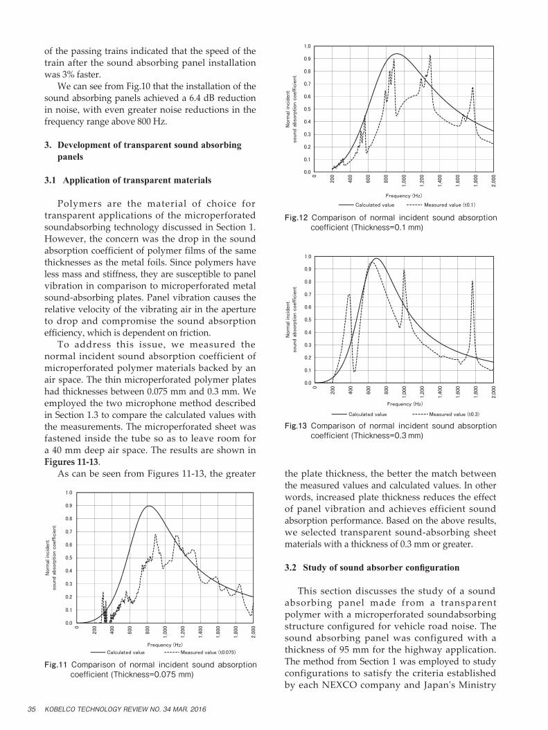
of the passing trains indicated that the speed of the train after the sound absorbing panel installation was 3% faster. We can see from Fig.10 that the installation of the sound absorbing panels achieved a 6.4 dB reduction in noise, with even greater noise reductions in the frequency range above 800 Hz.
3. Development of transparent sound absorbing panels
3.1 Application of transparent materials
Polymers are the material of choice for transparent applications of the microperforated soundabsorbing technology discussed in Section 1. However, the concern was the drop in the sound absorption coefficient of polymer films of the same thicknesses as the metal foils. Since polymers have less mass and stiffness, they are susceptible to panel vibration in comparison to microperforated metal sound-absorbing plates. Panel vibration causes the relative velocity of the vibrating air in the aperture to drop and compromise the sound absorption efficiency, which is dependent on friction. To address this issue, we measured the normal incident sound absorption coefficient of microperforated polymer materials backed by an air space. The thin microperforated polymer plates had thicknesses between 0.075 mm and 0.3 mm. We employed the two microphone method described in Section 1.3 to compare the calculated values with the measurements. The microperforated sheet was fastened inside the tube so as to leave room for a 40 mm deep air space. The results are shown in Figures 11-13. As can be seen from Figures 11-13, the greater the plate thickness, the better the match between
the measured values and calculated values. In other words, increased plate thickness reduces the effect of panel vibration and achieves efficient sound absorption performance. Based on the above results, we selected transparent sound-absorbing sheet materials with a thickness of 0.3 mm or greater.
3.2 Studyofsoundabsorberconfiguration
This section discusses the study of a sound absorbing panel made from a transparent polymer with a microperforated soundabsorbing structure configured for vehicle road noise. The sound absorbing panel was configured with a thickness of 95 mm for the highway application. The method from Section 1 was employed to study configurations to satisfy the criteria established by each NEXCO company and Japan's Ministry
Fig.11 Comparison of normal incident sound absorption coefficient (Thickness=0.075 mm)
0.0
0.1
0.2
0.3
0.4
0.5
0.6
0.7
0.8
0.9
1.0
0
200
400
600
800
1,0
00
1,2
00
1,4
00
1,6
00
1,8
00
2,0
00
Norm
al inc
iden
tso
und
abso
rption
coef
fici
ent
Frequency (Hz)
Calculated value Measured value (t0.075)
Fig.12 Comparison of normal incident sound absorption coefficient (Thickness=0.1 mm)
0.0
0.1
0.2
0.3
0.4
0.5
0.6
0.7
0.8
0.9
1.0
0
200
400
600
800
1,0
00
1,2
00
1,4
00
1,6
00
1,8
00
2,0
00
Norm
al incid
ent
sound a
bso
rption c
oeff
icie
nt
Frequency (Hz)
Calculated value Measured value (t0.1)
Fig.13 Comparison of normal incident sound absorption coefficient (Thickness=0.3 mm)
0.0
0.1
0.2
0.3
0.4
0.5
0.6
0.7
0.8
0.9
1.0
0
200
400
600
800
1,0
00
1,2
00
1,4
00
1,6
00
1,8
00
2,0
00
Norm
al incid
ent
sound
abso
rption c
oeffic
ient
Frequency (Hz)
Calculated value Measured value (t0.3)
KOBELCO TECHNOLOGY REVIEW NO. 34 MAR. 201635

of Land, Infrastructure, Transport and Tourism for road noise sound absorbing panels (Sound absorption coefficient of 0.7 or greater for 400 Hz and 0.8 or greater for 1 kHz, using the reverberation room method). Table 1 describes the configurations for the panels. Fig.14 shows the calculated results for the normal incident sound absorption coefficient.
3.3 Development of commercial transparent sound- absorbing panel
Based on the study above, a prototype transparent sound absorbing panel was fabricated to product-level specifications. The sound absorption coefficient of the prototype was measured with the reverberation room method. Fig.15 is a schematic drawing of the prototype panel and Fig.16 depicts the external appearance of the prototype. Fig.17 presents the sound absorption coefficient measurement results from the reverberation
room method. The results confirm that the sound-absorbing performance satisfies the above-mentioned criteria as designed. We also verified that one can adequately see through the panel (as can be seen in Fig.16). This study therefore verifies that the
Fig.14 Normal incident sound absorption coefficient
0.0
0.1
0.2
0.3
0.4
0.5
0.6
0.7
0.8
0.9
1.0
100
125
160
200
250
315
400
500
630
800
1,0
00
1,2
50
1,6
00
2,0
00
2,5
00
3,1
50
4,0
00
5,0
00
Norm
al incid
ent
sound
abso
rption c
oeff
icie
nt
1/3 Octave band frequency (Hz)
Table 1 Configuration of the sound absorber structure
Constitution
DimensionDesign element
Surface plate thickness 2 mm
Surface plate aperture ratio 9.0%
Surface plate aperture diameter 1.9 mm
Air space depth 25 mm
First film thickness 0.5 mm
First film aperture ratio 0.9%
First film aperture diameter 0.4 mm
Air space depth 25 mm
Second film thickness 0.5 mm
Second film aperture ratio 0.3%
Second film aperture diameter 0.4 mm
Air space depth 27 mm
Back plate thickness 8 mm
Fig.15 Schematic drawing of prototype panel
Fig.16 External appearance of transparent sound absorbing panel
Fig.17 Sound absorption coefficient from reverberation room method
0.0
0.1
0.2
0.3
0.4
0.5
0.6
0.7
0.8
0.9
1.0
100
125
160
200
250
315
400
500
630
800
1,0
00
1,2
50
1,6
00
2,0
00
2,5
00
3,1
50
4,0
00
5,0
00
Sound
abso
rption c
oeffic
ient
from
the r
eve
rbera
tion r
oom
meth
od
1/3 Octave band frequency (Hz)
Product data
Target values
KOBELCO TECHNOLOGY REVIEW NO. 34 MAR. 2016 36

sound absorbing panel is both sound absorbing and transparent. Since its development, this product has been officially selected by Shizuoka Prefecture for use on its prefectural roads and by the Nagoya Expressway Public Corporation. Fig.18 is an example of an installation for the Nagoya Expressway.
Conclusions
Since sound absorbing panels constructed with thin microperforated plates and foils and air
spaces can be designed with optimized frequency characteristics, sound absorbers that match the noise characteristics of the target noise can be manufactured. The development of microperforated sound absorbing panels for rail and road noise applications using this technology contributes to the reduction of traffic noise. Additionally, commercial sound absorbing panel products that are both sound absorbing and transparent basically do not exist for the noise barrier market at this time. Much growth is anticipated for such sound absorbing panels where visibility and translucency are requirements. Therefore, microperforated sound absorbing panels have potential for a broad array of applications and hold much promise going forward.
References
1) M. Horio et al. Kobe Steel Engineering Reports. 2014, Vol.65, No.1, p.84-88.
2) I. Yamagiwa et al. Proceedings of the Autumn Meeting of the Institute of Noise Control Engineering Japan. 2013, p.289-292.
3) T. Yamada et al. Proceedings of the 17th Environmental Engineering Symposium. 2007-7-19/20, p.39-41.
4) H.Utsuno et al. The Journal of the Acoustical Society of America. 1989, Vol.86, No.2, p.637-643.
Fig.18 Installation example
KOBELCO TECHNOLOGY REVIEW NO. 34 MAR. 201637