Eclipse ThermJet Burners - relevant. solutions
24
Eclipse ThermJet Burners Model TJ0015 - 2000 Version 2 Operating Instructions Edition 9.14 Distributed by Relevant Solutions | 1.888.858.3647 | relevantsolutions.com
Transcript of Eclipse ThermJet Burners - relevant. solutions

Eclipse ThermJet BurnersModel TJ0015 - 2000
Version 2
Operating Instructions Edition 9.14
Distributed by Relevant Solutions | 1.888.858.3647 | relevantsolutions.com
2
CopyrightCopyright 2007 by Eclipse, inc. All rights reservedworldwide. This publication is protected by federalregulation and shall not be copied, distributed,transmitted, transcribed or translated into any human orcomputer language, in any form or by any means, to anythird parties, without the express written consent ofEclipse, inc.
Disclaimer NoticeIn accordance with the manufacturer’s policy of continualproduct improvement, the product presented in thisbrochure is subject to change without notice or obligation.
The material in this manual is believed adequate for theintended use of the product. If the product is used forpurposes other than those specified herein, confirmationof validity and suitability must be obtained. Eclipsewarrants that the product itself does not infringe upon anyUnited States patents. No further warranty is expressed orimplied.
Liability & WarrantyWe have made every effort to make this manual asaccurate and complete as possible. Should you find errorsor omissions, please bring them to our attention so that wemay correct them. In this way we hope to improve ourproduct documentation for the benefit of our customers.Please send your corrections and comments to ourTechnical Documentation Specialist.
It must be understood that Eclipse’s liability for its product,whether due to breach of warranty, negligence, strictliability, or otherwise is limited to the furnishing ofreplacement parts and Eclipse will not be liable for anyother injury, loss, damage or expenses, whether direct orconsequential, including but not limited to loss of use,
income, or damage to material arising in connection withthe sale, installation, use of, inability to use, or the repairor replacement of Eclipse’s products.
Any operation expressly prohibited in this manual, anyadjustment, or assembly procedures not recommended or authorized in these instructions shall void the warranty.
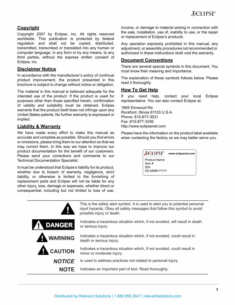
Document ConventionsThere are several special symbols in this document. Youmust know their meaning and importance.
The explanation of these symbols follows below. Pleaseread it thoroughly.
How To Get HelpIf you need help, contact your local Eclipserepresentative. You can also contact Eclipse at:
1665 Elmwood Rd.Rockford, Illinois 61103 U.S.A.Phone: 815-877-3031Fax: 815-877-3336http://www.eclipsenet.com
Please have the information on the product label availablewhen contacting the factory so we may better serve you.
Product NameItem #S/NDD MMM YYYY
www.eclipsenet.com
This is the safety alert symbol. It is used to alert you to potential personalinjurt hazards. Obey all safety messages that follow this symbol to avoidpossible injury or death.
Indicates a hazardous situation which, if not avoided, will result in deathor serious injury.
Indicates a hazardous situation which, if not avoided, could result indeath or serious injury.
Indicates a hazardous situation which, if not avoided, could result inminor or moderate injury.
Is used to address practices not related to personal injury.
Indicates an important part of text. Read thoroughly.NOTENOTICE
CAUTION
WARNING
Distributed by Relevant Solutions | 1.888.858.3647 | relevantsolutions.com

Table of Contents
3ThermJet, V2, Operating Instructions, Edition 9.14
Introduction............................................................................................................................... 4
Product Description .............................................................................................................. 4
Audience .............................................................................................................................. 4
ThermJet Documents ........................................................................................................... 4
Purpose ................................................................................................................................ 4
Safety ......................................................................................................................................... 5
Safety Warnings ................................................................................................................... 5
Capabilities........................................................................................................................... 5
Operator Training ................................................................................................................. 5
Replacement Parts............................................................................................................... 5
Installation................................................................................................................................. 6
Handling ............................................................................................................................... 6
Storage................................................................................................................................. 6
Position of Components ....................................................................................................... 6
Approval of Components...................................................................................................... 6
Checklist Before Installation................................................................................................. 7
Prepare the Burner............................................................................................................... 7
Burner Installation ................................................................................................................ 8
Piping Installation ................................................................................................................. 11
Valve Installation .................................................................................................................. 11
Checklist After Installation.................................................................................................... 12
Prepare for Adjustment ........................................................................................................ 12
Adjustment, Start & Stop ......................................................................................................... 13
Adjustment ........................................................................................................................... 13
Modulating Gas and Air Ratio System ................................................................................. 13
Fixed-Air System.................................................................................................................. 16
Set the Bypass Pilot Gas (Optional)..................................................................................... 17
Start Procedure .................................................................................................................... 18
Stop Procedure .................................................................................................................... 18
Maintenance & Troubleshooting ............................................................................................. 19
Maintenance......................................................................................................................... 19
Monthly Checklist ................................................................................................................. 19
Yearly Checklist.................................................................................................................... 19
Troubleshooting Procedures ................................................................................................ 20
Appendix ................................................................................................................................... i
Notes.......................................................................................................................................... ii
Distributed by Relevant Solutions | 1.888.858.3647 | relevantsolutions.com

Introduction
4ThermJet, V2, Operating Instructions, Edition 9.14
Product Description
The ThermJet is a nozzle-mix burner that is designed tofire an intense stream of hot gases through a combustorusing ambient combustion air.
The high velocity of the gases improves temperatureuniformity, product quality and system efficiency.
The ThermJet burner comes in two types:
• High Velocity (HV)
• Medium Velocity (MV)
Flame velocity information is available in Datasheets205-1 through 205-13.
The gas velocity can be as high as 500 ft/s for the HighVelocity burner, and 250 ft/s for the Medium Velocityburner.
Figure 1.1. ThermJet Burner
Audience
This manual has been written for people who are alreadyfamiliar with all aspects of a nozzle-mix burner and its add-on components, also referred to as “the burner system”.
These aspects are:
• Installation
• Use
• Maintenance
The audience is expected to have previous experiencewith this type of equipment.
ThermJet DocumentsInstallation Guide No. 205
• This document
Datasheet, Series No. 205-1 through 205-13
• Available for individual ThermJet models
• Required to complete installation
Design Guide No. 205
• Used with Datasheet to complete installation
Related Documents
• EFE 825 (Combustion Engineering Guide)
• Eclipse Bulletins and Info Guides: 610, 710, 720,730, 742, 744, 760, 930, I-354
Purpose
The purpose of this manual is to ensure that you carry outthe installation of a safe, effective, and trouble freecombustion system.
1
Distributed by Relevant Solutions | 1.888.858.3647 | relevantsolutions.com

Safety
5
Important notices which help provide safe burneroperation will be found in this section. To avoid personalinjury and damage to the property or facility, the followingwarnings must be observed. All involved personnel shouldread this entire manual carefully before attempting to startor operate this system. If any part of the information in thismanual is not understood, contact Eclipse beforecontinuing.
Safety Warnings
■ The burners, described herein, are designed to mixfuel with air and burn the resulting mixture. All fuelburning devices are capable of producing fires andexplosions if improperly applied, installed,adjusted, controlled or maintained.
■ Do not bypass any safety feature; fire or explosioncould result.
■ Never try to light a burner if it shows signs ofdamage or malfunction.
■ The burner and duct sections are likely to haveHOT surfaces. Always wear the appropriateprotective equipment when approaching theburner.
■ Eclipse products are designed to minimize the useof materials that contain crystalline silica.Examples of these chemicals are: respirablecrystalline silica from bricks, cement or othermasonry products and respirable refractoryceramic fibers from insulating blankets, boards, orgaskets. Despite these efforts, dust created bysanding, sawing, grinding, cutting and otherconstruction activities could release crystallinesilica. Crystalline silica is known to cause cancer,and health risks from the exposure to thesechemicals vary depending on the frequency andlength of exposure to these chemicals. To reducethe risk, limit exposure to these chemicals, work ina well-ventilated area and wear approved personalprotective safety equipment for these chemicals.
■ This manual provides information regarding theuse of these burners for their specific designpurpose. Do not deviate from any instructions orapplication limits described herein without writtenapproval from Eclipse.
CapabilitiesOnly qualified personnel, with sufficient mechanicalaptitude and experience with combustion equipment,should adjust, maintain or troubleshoot any mechanical orelectrical part of this system. Contact Eclipse for anyneeded commissioning assistance.
Operator TrainingThe best safety precaution is an alert and trainedoperator. Train new operators thoroughly and have themdemonstrate an adequate understanding of theequipment and its operation. A regular retraining scheduleshould be administered to ensure operators maintain ahigh degree of proficiency. Contact Eclipse for any neededsite-specific training.
Replacement PartsOrder replacement parts from Eclipse only. All Eclipseapproved valves or switches should carry UL, FM, CSA,CGA and/or CE approval where applicable.
DANGER
WARNING
NOTICE
2
Distributed by Relevant Solutions | 1.888.858.3647 | relevantsolutions.com

Installation 3
In this section you will find the information and instructionsthat you need to install the burner.Handling• Make sure that the area is clean.
• Protect the components from the weather, damage, dirt and moisture.
• Protect the components from excessive temperatures and humidity.
• Take care not to drop or damage components.
Storage• Make sure that the components are clean and free
of damage.
• Store the components in a cool, clean, dry room.
• After you have made sure that everything is present and in good condition, keep the components in the original package as long as possible.
■ When the refractory combustion block is suppliedwith the burner, it is critical that the instructionsfor handling and storage are followed. Therefractory should be considered fragile; improperhandling and storage will cause premature failure.
Position of ComponentsThe position and amount of components are determinedby the kind of control method chosen. All the controlmethods can be found in Design Guide 205. Follow one ofthe schematics in the System Design chapter to build yoursystem.
Approval of ComponentsLimit Controls & Safety Equipment
All limit controls and safety equipment must comply withall applicable local codes and/or standards and must belisted for combustion safety by an independent testingagency. Typical application examples include:
• American: NFPA 86 with listing marks from UL, FM,CSA
• European: EN 746-2 with CE mark from TuV,Gastec, Advantica
Electrical Wiring
All the electrical wiring must comply with all applicablelocal codes and/or standards such as:
• NFPA Standard 70
• IEC60364
• CSA C22
• BS7671
Gas Piping
All the gas piping must comply with all applicable localcodes and/or standards such as:
• NFPA Standard 54
• ANSI Z223
• EN 746-2
Where to Get the Standards:
The NFPA Standards are available from: National Fire Protection Agency Batterymarch ParkQuincy, MA 02269www.nfpa.org
The ANSI Standards are available from: American National Standard Institute 1430 BroadwayNew York, NY 10018www.ansi.org
The UL Standards are available from: 333 Pfingsten RoadNorthbrook, IL 60062www.ul.com
The FM Standards are available from: 1151 Boston-Providence TurnpikePO Box 9102Norwood, MA 02062www.fmglobal.com/approvals
NOTICE
6ThermJet, V2, Operating Instructions, Edition 9.14
Distributed by Relevant Solutions | 1.888.858.3647 | relevantsolutions.com

Information on the EN standards and where to getthem is available from: Comité Européen de Normalisation Stassartstraat 36B-1050 BrusselsPhone: +32-25196811Fax: +32-25196819www.cen.eu
Comité Européen de Normalisation Electronique Stassartstraat 36B-1050 BrusselsPhone: +32-25196871Fax: +32-25196919www.cenelec.org
Checklist Before InstallationIntake
To admit fresh combustion air from outdoors, provide anopening in the room of at least one square inch per 4,000Btu/h. If there are corrosive fumes or materials in the air,then supply the burner with clean air from anuncontaminated area, or provide a sufficient air filteringsystem.
Exhaust
Do not allow exhaust to accumulate in the work area.Provide some positive means for exhausting them fromthe furnace and the building.
Access
Make sure that you install the burner in such a way thatyou can get easy access for inspection and maintenance.
Environment
Make sure the local environment matches the originaloperating specifications. Check the following items:
• Voltage, frequency and stability of the electricalpower
• Type and supply pressure of the fuel
• Availability of enough fresh, clean combustion air
• Humidity, altitude and temperature of air
• Presence of damaging corrosive gases in the air
Prepare the Burner
Several components must be installed on a burner beforeit can operate. Installation instructions follow.
It is possible to change the relative position of the gas inletwith respect to the air inlet. This can be convenient for therouting of the piping.
Rotate the Rear Cover (Optional)
To rotate the rear cover, do the following (see Figure 3.1):
1. Disconnect the piping at a union in the piping or theinlet flanges provided on the burner.
NOTE: Be careful not to lose or damage the orifice plateor the o-rings.
2. Remove the four bolts .
3. Remove the rear cover from the burner housing .
4. Rotate the rear cover to the position that you want.
5. Put the rear cover in position against the burnerhousing .
6. Install the four bolts .
7. Reconnect the piping. Make sure that the o-rings showno signs of damage.
Figure 3.1. Rotate the Rear Cover
➋
➌
➍
➊
➋
➌
➍
7ThermJet, V2, Operating Instructions, Edition 9.14
Distributed by Relevant Solutions | 1.888.858.3647 | relevantsolutions.com
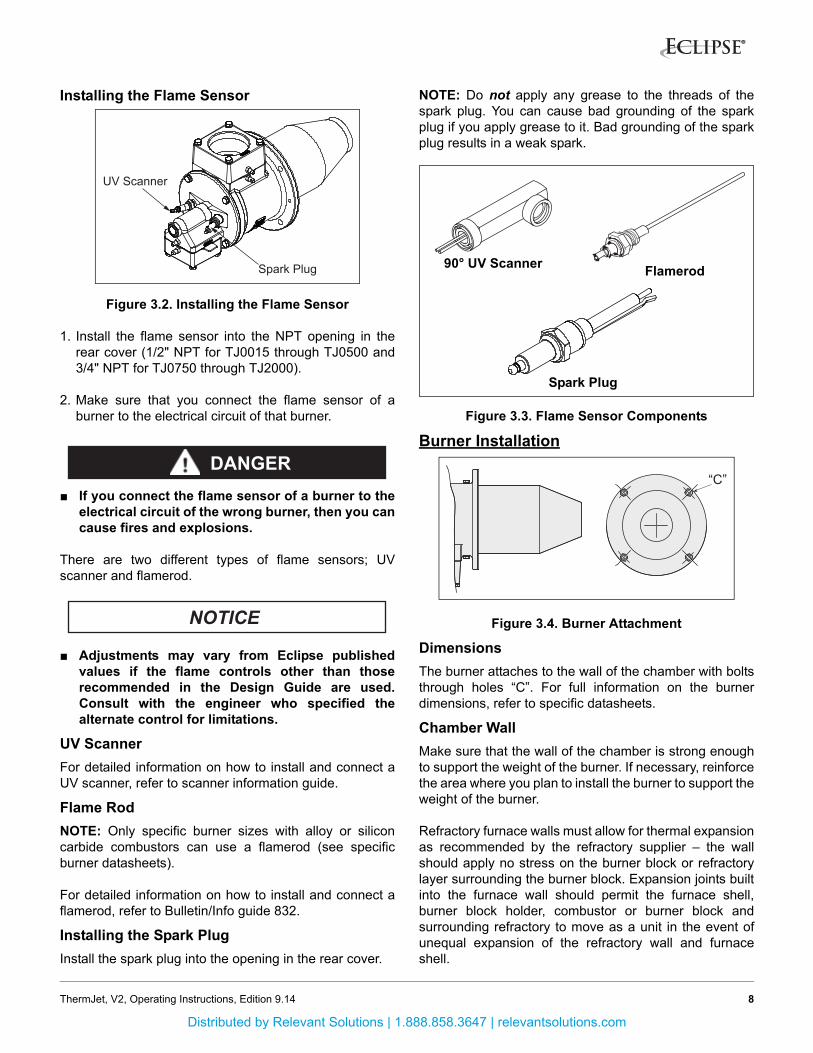
Installing the Flame Sensor
Figure 3.2. Installing the Flame Sensor
1. Install the flame sensor into the NPT opening in therear cover (1/2" NPT for TJ0015 through TJ0500 and3/4" NPT for TJ0750 through TJ2000).
2. Make sure that you connect the flame sensor of aburner to the electrical circuit of that burner.
■ If you connect the flame sensor of a burner to theelectrical circuit of the wrong burner, then you cancause fires and explosions.
There are two different types of flame sensors; UVscanner and flamerod.
■ Adjustments may vary from Eclipse publishedvalues if the flame controls other than thoserecommended in the Design Guide are used.Consult with the engineer who specified thealternate control for limitations.
UV Scanner
For detailed information on how to install and connect aUV scanner, refer to scanner information guide.
Flame Rod
NOTE: Only specific burner sizes with alloy or siliconcarbide combustors can use a flamerod (see specificburner datasheets).
For detailed information on how to install and connect aflamerod, refer to Bulletin/Info guide 832.
Installing the Spark Plug
Install the spark plug into the opening in the rear cover.
NOTE: Do not apply any grease to the threads of thespark plug. You can cause bad grounding of the sparkplug if you apply grease to it. Bad grounding of the sparkplug results in a weak spark.
Figure 3.3. Flame Sensor Components
Burner Installation
Figure 3.4. Burner Attachment
Dimensions
The burner attaches to the wall of the chamber with boltsthrough holes “C”. For full information on the burnerdimensions, refer to specific datasheets.
Chamber Wall
Make sure that the wall of the chamber is strong enoughto support the weight of the burner. If necessary, reinforcethe area where you plan to install the burner to support theweight of the burner.
Refractory furnace walls must allow for thermal expansionas recommended by the refractory supplier – the wallshould apply no stress on the burner block or refractorylayer surrounding the burner block. Expansion joints builtinto the furnace wall should permit the furnace shell,burner block holder, combustor or burner block andsurrounding refractory to move as a unit in the event ofunequal expansion of the refractory wall and furnaceshell.
Spark Plug
UV Scanner
DANGER
NOTICE
Flamerod90° UV Scanner
Spark Plug
“C”
8ThermJet, V2, Operating Instructions, Edition 9.14
Distributed by Relevant Solutions | 1.888.858.3647 | relevantsolutions.com

The combustor or combustion block must not extendbeyond the inside of the furnace wall more than 1".Beyond this length it is necessary to add a spacer on theoutside of the furnace to keep the end of the combustor orcombustion block within 1/2" of the end of the wall.
Figure 3.5. ThermJet Combustor Position
If the combustor or burner block is shorter than thefurnace wall thickness the block or combustor should berecessed into the wall. To prevent refractory overheating,a 45° chamfer should be applied.
Avoid Losses
To make sure that heat does not go back to the casing ofthe chamber, it is important that the radial clearancearound the firing tube is filled with ceramic fiber.
Alloy Combustor (Figure 3.6)
1. Make sure the gasket is installed between theburner and the chamber wall .
2. Make sure that gasket does not leak.
3. Check the size of the clearance. If the gap aroundthe firing tube is larger than 1/2", then pack the gap withceramic fiber .
NOTE: Do not insulate the end of the combustion tube“tip”. Do not recess the combustion tube into the furnacewall.
Figure 3.6. Alloy Combustor
Silicon Carbide (SiC) Combustor Only (Figure 3.7)
1. Make sure the gasket is installed between theburner flange and chamber wall .
2. Make sure gasket is installed between SiC tube andflange .
3. Make sure neither gasket or leaks.
4. Check the size of the clearance. If the gap aroundthe firing tube is larger than 1/2", then pack the gap withceramic fiber .
Figure 3.7. Silicon Carbide
If this gap is larger than
1/2" fill it with insulation
Position the faceof the burner block
approximately in linewith the furnace wall
if possible
Approximate 45° angle between burner& furnace wall
�
� �
�
3
1 2
4
5
6
9ThermJet, V2, Operating Instructions, Edition 9.14
Distributed by Relevant Solutions | 1.888.858.3647 | relevantsolutions.com

Refractory Block (Figure 3.8)
1. Make sure gasket is installed between burner and block holder .
2. Make sure gasket is installed between block holder and chamber wall .
3. Support the weight of refractory block with hard brickwork anchored to the furnace shell . Fill the 1/2"space between block and the three unsupportedsides with soft gasket material .
Figure 3.8. Refractory Block
Large Refractory Blocks
On sizes TJ0500 thru TJ2000; the block must besurrounded by a collar made of brick, plastic refractory, ora castable refractory of at least 4" (10 cm) minimumthickness on all sides of the block. If the collar is cast
around the block, a thin plastic film (i.e. Saran Wrap® or
Glad Wrap®) should be wrapped around the block to keepmoisture from leaching into it. The collar should beanchored to the furnace shell with suitable anchors andmust be constructed to rest on a surface capable ofsupporting its weight, such as a hearth or a solid refractoryor brick wall. For furnaces that are unable to support theweight of the refractory block, a stainless steel shelf can bewelded to the shell to support the collar.
Refractory Block Curing Schedule
The refractory block was cured at the factory up to atemperature of at least 550°F (288°C). Final curing shouldbe done after installation. The recommended curingschedule is:
• Ambient to 600°F (315°C) at 100°F (55°C) per hour.
• 600°F (315°C) to 1000°F (540°C) at 25°F (14°C) perhour. Hold the refractory block at 1000°F (540°C) for12 hours.
• Cool or raise the operating temperature at a rate of100°F (55°C) per hour.
Please contact Eclipse with any questions regarding blockcuring.
After initial curing, blocks are to be heated or cooled at arate no faster than 200°F (93°C) per hour.
NOTE: The correct insulation of burner combustion blocksin furnaces results in longer block life and adds value byreducing downtime and maintenance.
Block Holder Temperature
Excessive block holder temperatures can causeproblems. Overheating can be reduced by carefullysealing the burner blocks in the wall to prevent theleakage of hot gases back to the furnace shell.
In high temperature (>1,400°F, 760°C) fiber-wall furnaceinstallations, the length of the metallic wrapper shouldextend no farther than the point in the wall where theinterface temperature is higher than 1800°F (760°C).
Vertical Down Firing Blocks (Figure 3.9)
1. Down firing blocks may be suspended by customersupplied hangers attached to the burner bodymounting bolts.
2. Hangers should be attached to structural support .
Figure 3.9. Vertical Down Firing Block
NOTE: Burner housings should not be insulated withoutcontacting Eclipse.
�
�
�
� �
�
�7
�
�
10ThermJet, V2, Operating Instructions, Edition 9.14
Distributed by Relevant Solutions | 1.888.858.3647 | relevantsolutions.com

Piping Installation
Figure 3.10. Piping Installation
Layout
Install the piping as shown in the schematics. Refer toChapter 3 of the ThermJet Design Guide No. 205.
Support the Piping
Use brackets or hangers to support the gas piping. If youhave questions, consult your local gas company.
Straight Run of Pipe Before a Metering Orifice
NOTE: There must be a run of pipe with a straight lengthof at least 10 pipe diameters before the burner meteringorifice. If you do not do this, the pressure readings will beinaccurate.
Pipe Connections
Install a pipe union in the gas line to the burner. Thissimplifies removal of the burner.
The use of flexible pipe nipples in the gas line to theburner is optional. Flexible nipples can absorb stress dueto heat expansion and slight misalignment.
NOTE: Flexible pipe nipples will cause inaccuratemetering orifice readings and may cause higher pressuredrops than equivalent standard pipe. Consider this whenyou size the gas lines.
Avoid Large Pressure Drops
NOTE: The pressure drop of the gas in the piping is acritical parameter. Make sure that the size of all the pipingis large enough to prevent excessive pressure losses.
Valve InstallationValve Orientation
Install all the valves in such a way that the arrow (ifpresent) on the valve body points in the direction of flow.
Figure 3.11. Valve Orientation
Gas Cocks
Make sure that the handle of a gas cock is at a right angleto the valve body when the valve is in the closed position.This is an important position indicator. If you do not dothis, someone may think that the gas cock is in the closedposition, while it is actually in the open position.
Gas Balancing Valves
A gas balancing valve is typically the same as a manualbutterfly valve. For more information, refer to "ManualButterfly Valves" below.
Manual Butterfly Valves
1. Install manual butterfly valves in accordance withBulletin/Info Guide 720.
2. Install manual butterfly valves in the gas line to theburner (optional).
NOTE: It is recommended that there is a run of pipe witha length of at least 10 pipe diameters between any flowaltering device and metering orifice on the burner.
Automatic Butterfly Valve
An automatic butterfly is driven by an actuator. Install thecontrol valve in accordance with Bulletin/Info Guide 720.
Ratio Regulator
• Connect an impulse line to the ratio regulator and airsupply line.
• Install the ratio regulator in accordance with Bulletin/Information Guide 742.
Bracket
Pipe Union
Closed Open
11ThermJet, V2, Operating Instructions, Edition 9.14
Distributed by Relevant Solutions | 1.888.858.3647 | relevantsolutions.com

Figure 3.12. Valves
Checklist After InstallationTo verify proper system installation, do the following:
1. Make sure that there are no leaks in the gas and airlines.
2. Make sure all the components of the flame monitoringcontrol system are properly installed. This includesverifying that all switches are installed in correctlocations and all wiring, pressure and impulse lines areproperly connected.
3. Make sure components of spark ignition system areinstalled and functioning properly.
4. Make sure that the blower rotates in the correctdirection. If incorrect, have a qualified electrician rewirethe blower to reverse its rotation.
5. Make sure all valves are installed in the proper locationand correctly oriented relative to the gas or air flowdirection.
Prepare for Adjustment
After installation of the burner system components iscomplete, the following steps should be followed in orderto prepare for adjustment:
1. Set the air pressure switch so that it drops out at 4" w.c.(10 mbar) below the pressure rating of the blower.
2. Set the low gas pressure switch at 4" w.c. (10 mbar)below the gas pressure measured at the inlet to themain gas valve train.
3. Set the high gas pressure switch so that it comes on at4" w.c. (10 mbar) above the gas pressure measured atthe inlet to the main gas valve train.
4. Close all the burner gas cocks.
5. Try to light a burner before the purge and other timershave finished their cycles. Make sure that the flamemonitoring system indicates a flame failure.
6. Trip out pressure switches and other limit interlocks.Make sure that the main gas valve train closes.
■ If simulated limits or simulated flame failures donot shut down the fuel system within the requiredfailure response time, immediately correct theproblem before proceeding.
ManualButterfly
Valve
AutomaticButterfly
ValveRatio
Regulator
DANGER
12ThermJet, V2, Operating Instructions, Edition 9.14
Distributed by Relevant Solutions | 1.888.858.3647 | relevantsolutions.com

Adjustment, Startand Stop
4
In this chapter you will find instructions on how to adjust asystem, and how to start and stop a system.■ Do not bypass any safety feature. You can causefires and explosions.
AdjustmentThere are two adjustment procedures. To adjust amodulating gas and air ratio system, refer to “ModulatingGas & Air Ratio System”. For a fixed-air system, refer to“Fixed-Air System”.
Modulating Gas & Air Ratio SystemIf you adjust an on-ratio system for the first time, you mustfollow these steps: (Refer to Figures in the ThermJetDesign Guide No. 205)
Step 1: Reset the System
1. Close the automatic gas valves and gas cocks.
2. Fully open the manual air butterfly valve at each burner.
a.Drive the automatic zone air control valve to high fire.
b.Adjust the automatic zone air control valve so that itis fully open.
3. Start the blower.
■ Make sure that the blower rotates in the correctdirection. If incorrect, have a qualified electricianrewire the blower to reverse its rotation.
Step 2: Set High Fire Air
Figure 4.1. Set High Fire Air
1. Set the system to high fire, but DO NOT ignite theburner(s).
2. Use the air curves from the appropriate ThermJet datasheet to find the differential air pressure needed at high fire. This is the target value for high fire.
3. Set high fire air using the instructions for either a single burner system or multiple burner system below. (See Figure 4.2)
To set high fire air on a single burner system:
NOTE: A pressure tap is open when the screw insidethe tap is unscrewed approximately half a turn.
a.Make sure that pressure taps A and C are open.
b.Connect the manometer to taps A and C (across theair orifice).
c.Adjust the manual butterfly valve until the high firedifferential air pressure is at the target value.
d.Remove the manometer.
e.Close the pressure taps.
To set high fire air on a multiple burner system:
a.Make sure that pressure taps A and C of the first burner are open.
b.Connect the manometer to taps A and C of the firstburner (across the air orifice).
c.Adjust the zone air manual butterfly valve to achievethe target value for the first burner.
DANGER
NOTICE
Tap A
13ThermJet, V2, Operating Instructions, Edition 9.14
Distributed by Relevant Solutions | 1.888.858.3647 | relevantsolutions.com
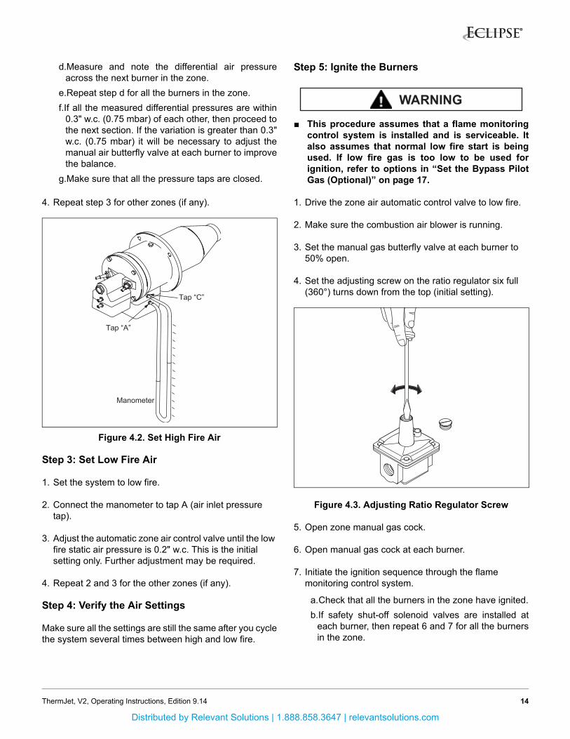
d.Measure and note the differential air pressureacross the next burner in the zone.
e.Repeat step d for all the burners in the zone.
f.If all the measured differential pressures are within0.3" w.c. (0.75 mbar) of each other, then proceed tothe next section. If the variation is greater than 0.3"w.c. (0.75 mbar) it will be necessary to adjust themanual air butterfly valve at each burner to improvethe balance.
g.Make sure that all the pressure taps are closed.
4. Repeat step 3 for other zones (if any).
Figure 4.2. Set High Fire Air
Step 3: Set Low Fire Air
1. Set the system to low fire.
2. Connect the manometer to tap A (air inlet pressure tap).
3. Adjust the automatic zone air control valve until the low fire static air pressure is 0.2" w.c. This is the initial setting only. Further adjustment may be required.
4. Repeat 2 and 3 for the other zones (if any).
Step 4: Verify the Air Settings
Make sure all the settings are still the same after you cyclethe system several times between high and low fire.
Step 5: Ignite the Burners
■ This procedure assumes that a flame monitoringcontrol system is installed and is serviceable. Italso assumes that normal low fire start is beingused. If low fire gas is too low to be used forignition, refer to options in “Set the Bypass PilotGas (Optional)” on page 17.
1. Drive the zone air automatic control valve to low fire.
2. Make sure the combustion air blower is running.
3. Set the manual gas butterfly valve at each burner to 50% open.
4. Set the adjusting screw on the ratio regulator six full (360°) turns down from the top (initial setting).
Figure 4.3. Adjusting Ratio Regulator Screw
5. Open zone manual gas cock.
6. Open manual gas cock at each burner.
7. Initiate the ignition sequence through the flame monitoring control system.
a.Check that all the burners in the zone have ignited.
b.If safety shut-off solenoid valves are installed ateach burner, then repeat 6 and 7 for all the burnersin the zone.
Tap “A”
Tap “C”
Manometer
WARNING
14ThermJet, V2, Operating Instructions, Edition 9.14
Distributed by Relevant Solutions | 1.888.858.3647 | relevantsolutions.com

8. If all the burners have ignited, drive the zone air butterfly valve to high fire. Verify flame is present at each burner. If burners do not light, add a 1/2 turndown on the proportionator, and repeat steps 7 and 8.
9. Verify that air pressure drops have remained the same.
10.If air pressure drop is too high, close down the zone manual air butterfly valve.
11.If air pressure drop is too low, open the zone manual air butterfly valve.
Step 6: Set High Fire Gas
Figure 4.4. Set High Fire Gas
1. Use the gas curve from the appropriate ThermJetdatasheet for the gas being used to find the differentialgas pressure needed at high fire. This is the targetvalue for high fire.
2. Connect the manometer to taps B and D (across the gas orifice, see Figure 4.4).
3. Measure the high fire differential gas pressure for the first burner.
4. Adjust the gas butterfly valve at the burner until the gas flow is at the target value.
5. Repeat 3 thru 4 for the other burners in the zone.
6. Check the gas pressure at the inlet to the zone ratio regulator. This should be at least 5" w.c. (12.5 mbar) higher than the loading line pressure. It should not exceed the maximum pressure rating of the ratio regulator.
■ Insufficient gas inlet pressure may cause theproportionator to remain fully open as the burnersystem turns down from high fire, causing excessfuel operation and possible accumulation ofunburned fuel in the chamber. In extreme cases,this may cause explosions or fires.
Step 7: Set Low Fire Gas
1. Drive the system to low fire.
2. Use the gas curve from the appropriate ThermJet datasheet for the gas being used to determine the differential gas pressure required for low fire. This is your target value for low fire.
3. Measure the gas pressure at the first burner.
4. Adjust the ratio regulator until the gas flow is on the target value. (Refer to Bulletin 742 for adjustment.)
NOTE: It is very difficult to measure the very lowpressures experienced at low fire, and it may benecessary to rely on visual inspection. This is especiallytrue when gas turndowns in excess of 10:1 are beingused. The main intent is to provide a clean stable flamewith a good flame signal that will not cause the furnacetemperature to overshoot.
If the pressure required is too low to be measured, adjustthe ratio regulator until a gas flow is obtained that willprovide a clean stable flame with a strong flame signal.
Step 8: Verify the Gas Settings
Make sure that all settings are still the same after cyclingthe system several times between high and low fire.
NOTE: When all the settings have been completed, markthe position of the indicator on the butterfly valves toindicate valve position.
Tap “D”
Tap “B”
Manometer
WARNING
15ThermJet, V2, Operating Instructions, Edition 9.14
Distributed by Relevant Solutions | 1.888.858.3647 | relevantsolutions.com

Fixed Air System
When you adjust a fixed-air system for the first time, youmust follow these steps:
Step 1: Reset the System
1. Close the automatic gas valves and gas cocks.
2. Fully open the manual air butterfly valve at each burner.
a.Drive the automatic zone air control valve to high fire.
b.Adjust the automatic zone air control valve so that itis fully open.
3. Set the manual gas butterfly valve at each burner to 50% open.
4. Start the blower.
NOTE: Make sure that the blower rotates in the correctdirection. If incorrect, have a qualified electrician rewirethe blower to reverse its rotation.
Step 2: Set High Fire Air (Figure 4.2)
1. Set the system to high fire, but DO NOT ignite theburner(s).
2. Use the air curves in “Orifice Curves” from the appropriate ThermJet datasheet to find the differential air pressure needed at high fire. This is now the target value for high fire.
3. Set high fire air using the instructions for either a single burner system or multiple burner system below.
NOTE: A pressure tap is open when the screw inside thetap is unscrewed approximately half a turn.
Single Burner System:
a.Make sure that pressure taps A and C of the burner are open.
b.Connect the manometer to taps A and C (across theair orifice).
c.Adjust the manual butterfly valve until the high firedifferential air pressure is at the target value.
d.Remove the manometer.
e.Close the pressure taps.
Multiple Burner System:
a.Make sure that pressure taps A and C of the first burner are open.
b.Connect the manometer to taps A and C of the firstburner (across the air orifice).
c.Adjust the manual butterfly valve for the zone, untilthe high-fire differential air pressure is at the targetvalue for the first burner.
d.Measure the differential air pressure across the nextburner in the zone.
e.Repeat step d for all the burners in the zone.
f.If all the measured differential pressures are within0.3" w.c (0.75 mbar) of each other, then proceed tothe next section. If the variation is greater than 0.3"w.c. (0.75 mbar) it is necessary to adjust the manualair butterfly valve at each burner to improve thebalance.
g.Make sure that all the pressure taps are closed.
4. Repeat 3 for other zones (if any).
Step 3: Ignite the Burners
■ This procedure assumes that a flame monitoringcontrol system is installed and is serviceable. Italso assumes that normal low fire start is beingused. If low fire gas is too low to be used forignition, refer to options in “Set the Bypass PilotGas (Optional)” on page 17.
1. Drive the zone gas automatic butterfly valve to low fire.
2. Make sure the combustion air blower is running.
3. Set the burner manual gas butterfly valve to low fire.
4. Set the adjusting screw on the ratio regulator six full (360°) turns down from the top (initial setting).
5. Select the valve according to the control method:
a.With high/low control:Set the gas bypass butterfly valve 25% open.
b.With modulating gas control:Set the zone gas automatic butterfly value toapproximately 10% open. Stroke the valve to theopen position to ensure 100% open. Readjust ifnecessary.
WARNING
16ThermJet, V2, Operating Instructions, Edition 9.14
Distributed by Relevant Solutions | 1.888.858.3647 | relevantsolutions.com

6. Open the zone gas manual gas cock.
7. Open the manual gas cock at each burner.
8. Initiate the ignition sequence through the flamemonitoring control system.
9. Check that all the burners in the zone have ignited.
10.If shut-off solenoid valves are installed at each burner,then repeat 6 and 7 for all the burners in the zone.
11.If all the burners have ignited, drive the zone to highfire. Verify flame is present at each burner.
Step 4: Set High Fire Gas (Figure 4.1)
1. Use the gas curves from the appropriate ThermJetdatasheet for the gas being used to find the differentialgas pressure needed at high fire. This is the targetvalue for high fire.
2. Connect the manometer to taps B and D (across thegas orifice, see Figure 4.4).
3. Measure the high fire differential gas pressure for thefirst burner.
4. Adjust the gas butterfly valve at the burner until the gasflow is at the target value.
5. Repeat 3 and 4 for the other burners in the zone.
6. Check the gas pressure at the inlet to the zone ratioregulator. This should be at least 5" w.c. (12.5 mbar)higher than the loading line pressure. It should notexceed the maximum pressure rating of the ratioregulator (optional).
■ Insufficient gas inlet pressure may cause theproportionator to remain fully open as the burnersystem turns down from high fire, causing excessfuel operation and possible accumulation ofunburned fuel in the chamber. In extreme cases,this may cause explosions or fires.
Step 5: Set Low Fire Gas
1. Drive the system to low fire.
2. Measure the gas pressure drop at the first burner.
3. Select the valve according to the control method:
a.With high/low control:Adjust the gas bypass butterfly valve (see ThermJetDesign Guide No. 205) until the minimum fire thatwill still maintain a strong flame signal is obtained.
b.With modulating gas control:Adjust the zone gas automatic butterfly valve (seeThermJet Design Guide No. 205) until the minimumfire that will still maintain a strong flame signal isobtained.
NOTE: It is very difficult to measure the very lowpressures experienced at low fire, and it may benecessary to rely on visual inspection. This is especiallytrue when gas turndowns in excess of 10:1 are beingused. The main intent is to provide a clean stable flamewith a good flame signal that will not cause the furnacetemperature to overshoot.
Step 6: Verify the Gas Settings
Make sure that all the settings are still the same after youhave cycled the system several times between high andlow fire.
NOTE: When all the settings have been completed, markthe position of the indicator on the butterfly valves toindicate valve position.
Set the Bypass Pilot Gas (Optional)1. Set the system to low fire.
2. Make sure that the blower is on.
■ Before you perform this procedure, make sure theflame monitoring control system is working.
3. Use the flame monitoring control system to start theignition and the bypass pilot gas for all the burners inthe zone.
4. Adjust the manual butterfly valve in the bypass line until you obtain reliable ignition within the required trial forignition time limit.
5. Repeat 4 for all the other burners and zones (if any).
WARNING
WARNING
17ThermJet, V2, Operating Instructions, Edition 9.14
Distributed by Relevant Solutions | 1.888.858.3647 | relevantsolutions.com

Start Procedure1. Start the blower.
2. Open all the gas cocks.
3. Start the ignition sequence.
4. Verify that flame is present at each burner.
■ If a burner does not light, and the system does notshut down automatically, then you must close themain gas cock. An uncontrolled flow of gas cancause fires and explosions.
■ Do not touch the ignition plug or the ignition wirewhen the ignition is on. You will get a shock.
Stop Procedure1. Close the following valves:
• The manual gas cock for each burner or zone
• The manual gas cock at the main control valve
• All the manual shut-off valves in the gas line upstream of the burner gas cock
2. Let the burners cool down. Keep the blower on until the chamber temperature is less than 1000°F (500°C) and then stop the blower.
■ Keeping the blower on after the burner is offprotects the burner and the other componentsfrom hot gases that flow back through the burner.
DANGER
NOTICE
18ThermJet, V2, Operating Instructions, Edition 9.14
Distributed by Relevant Solutions | 1.888.858.3647 | relevantsolutions.com
Maintenance and Troubleshooting
5
This chapter is divided into two sections:• Maintenance procedures
• Troubleshooting guide
Maintenance
Preventive maintenance is the key to a reliable, safe andefficient system. The core of any preventive maintenancesystem is a list of periodic tasks.
The following are suggestions for a monthly list and ayearly list.
NOTE: The monthly list and yearly lists are an averageinterval. If your environment is dirty, the intervals may beshorter.
Monthly Checklist1. Test (leak test) safety shut-off valves for tightness of
closure.
2. Test air pressure switch settings by checking switchmovements against pressure settings and comparingwith actual impulse pressure.
3. Visually check ignition cable and connectors.
4. Inspect impulse piping for leaks.
5. Clean and inspect all the burners.
6. Make sure that the following components are notdamaged or distorted:
• burner nozzle
• spark plugs
• flame sensors
• flame tube or combustion block
7. If applicable, remove and clean all the orifice plates.
Yearly Checklist1. Inspect flame-sensing devices for good condition and
cleanliness.
2. Check for proper inlet air/gas ratios.
3. Test all the alarm systems for proper signals.
4. Check ignition spark plugs and proper gap.
5. Check valve motors and control valves for free, smoothaction and adjustment.
6. Check for proper operation of the ventilatingequipment.
7. Test the interlock sequence of all safety equipment;manually make each interlock fail, noting that relatedequipment closes or stops as specified by themanufacturer.
8. Test flame monitoring control system by manuallyshutting off gas to burner.
9. Test main fuel hand-valves for operation.
10.Clean or replace the combustion air blower filter.
19ThermJet, V2, Operating Instructions, Edition 9.14
Distributed by Relevant Solutions | 1.888.858.3647 | relevantsolutions.com

Troubleshooting Procedures
Problem Possible Cause Solution
Cannot initiate start sequence Air pressure switch has not made contact
Check air pressure switch adjustment. Check air filter. Check blower rotation. Check outlet pressure from blower.
High gas pressure switch has tripped Check incoming gas pressure. Adjust gas pressure if necessary. Check pressure switch setting and operation.
Low gas pressure switch has tripped Check incoming gas pressure. Adjust gas pressure if necessary. Check pressure switch setting and operation.
Malfunction of flame monitoring control system such as shorted out flame sense or electrical noise in the sensor line
Have a qualified electrician investigate and rectify.
Purge cycle not completed Check flame monitoring control system or purge timer.
Main power is off Make sure power is on to control system.
No power to control unit Call qualified electrician to investigate.
Start-up sequence runs but burner does not light
No ignition: There is no power to the ignition transformer
Restore power to the ignition transformer.
No ignition: Open circuit between the ignition transformer and the spark plug
Repair or replace the wiring to the spark plug.
No ignition: The spark plug needs cleaning
Clean the spark plug.
No ignition: The spark plug is not correctly grounded to the burner
Clean the threads of the spark plug and the burner. Do not apply grease to the thread of the spark plug.
Too much gas: Improper gas valve train sequence
Verify solenoid valve is down-stream of proportionator.
Too much gas: Manual gas butterfly valves have been opened too far
Check pressures and settings against start-up report and adjust as necessary.
Too much gas: Gas pressure out of the main gas pressure regulator is too high
Check start-up setting. If necessary, remove regulator and investigate.
Not enough gas: The gas pressure out of the main gas pressure regulator is too low
Check start-up setting. Check regulator and adjust if necessary.
Not enough gas: Start gas solenoid valve does not open.
Check solenoid valve coil for proper orientation. Replace if necessary.
Not enough gas: Gas valve not open Check wiring to the automatic gas shut-off valve.
Not enough gas: Air in the gas line Check output from the flame safeguard. Open gas cock. Purge gas line.
20ThermJet, V2, Operating Instructions, Edition 9.14
Distributed by Relevant Solutions | 1.888.858.3647 | relevantsolutions.com
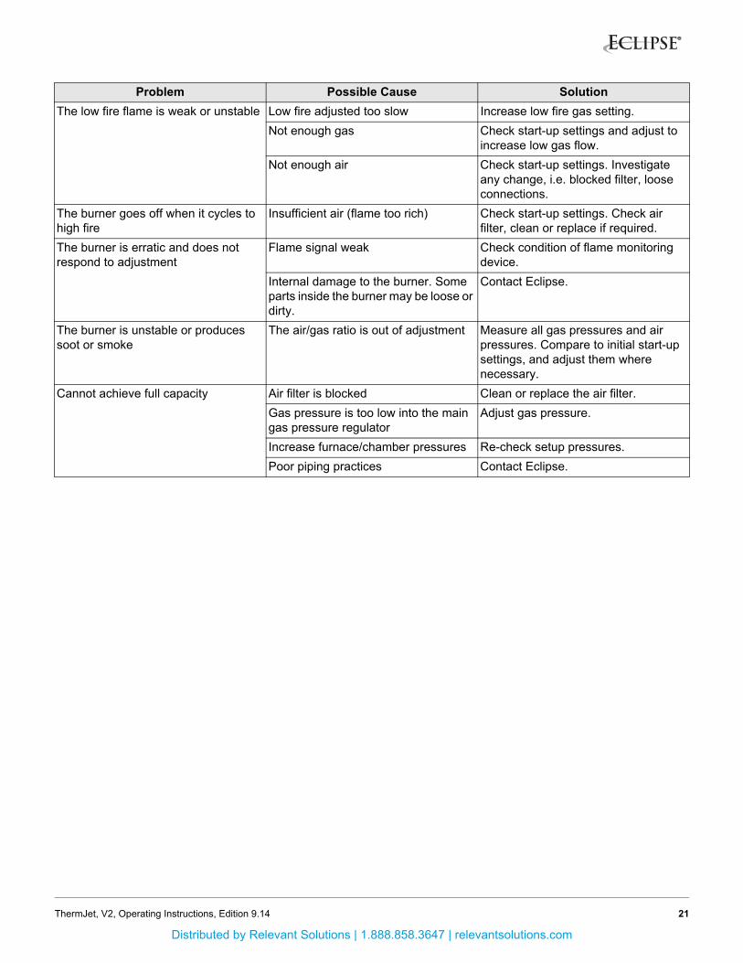
The low fire flame is weak or unstable Low fire adjusted too slow Increase low fire gas setting.
Not enough gas Check start-up settings and adjust to increase low gas flow.
Not enough air Check start-up settings. Investigate any change, i.e. blocked filter, loose connections.
The burner goes off when it cycles to high fire
Insufficient air (flame too rich) Check start-up settings. Check air filter, clean or replace if required.
The burner is erratic and does not respond to adjustment
Flame signal weak Check condition of flame monitoring device.
Internal damage to the burner. Some parts inside the burner may be loose or dirty.
Contact Eclipse.
The burner is unstable or produces soot or smoke
The air/gas ratio is out of adjustment Measure all gas pressures and air pressures. Compare to initial start-up settings, and adjust them where necessary.
Cannot achieve full capacity Air filter is blocked Clean or replace the air filter.
Gas pressure is too low into the main gas pressure regulator
Adjust gas pressure.
Increase furnace/chamber pressures Re-check setup pressures.
Poor piping practices Contact Eclipse.
Problem Possible Cause Solution
21ThermJet, V2, Operating Instructions, Edition 9.14
Distributed by Relevant Solutions | 1.888.858.3647 | relevantsolutions.com

AppendixConversion Factors
Metric to English
Metric to Metric
English to Metric
From To Multiply By
actual cubic meter/h (am³/h) actual cubic foot/h (acfh) 35.31
normal cubic meter/h (Nm³/h) standard cubic foot /h (scfh) 38.04
degrees Celsius (°C) degrees Fahrenheit (°F) (°C x 9/5) + 32
kilogram (kg) pound (lb) 2.205
kilowatt (kW) Btu/h 3415
meter (m) foot (ft) 3.281
millibar (mbar) inches water column ("w.c.) 0.402
millibar (mbar) pounds/sq in (psi) 14.5 x 10⁻³
millimeter (mm) inch (in) 3.94 x 10⁻²
MJ/Nm³ Btu/ft³ (standard) 26.86
From To Multiply By
kiloPascals (kPa) millibar (mbar) 10
meter (m) millimeter (mm) 1000
millibar (mbar) kiloPascals (kPa) 0.1
millimeter (mm) meter (m) 0.001
From To Multiply By
actual cubic foot/h (acfh) actual cubic meter/h (am³/h) 2.832 x 10⁻²
standard cubic foot /h (scfh) normal cubic meter/h (Nm³/h) 2.629 x 10⁻²
degrees Fahrenheit (°F) degrees Celsius (°C) (°F - 32) x 5/9
pound (lb) kilogram (kg) 0.454
Btu/h kilowatt (kW) 0.293 x 10⁻³
foot (ft) meter (m) 0.3048
inches water column ("w.c.) millibar (mbar) 2.489
pounds/sq in (psi) millibar (mbar) 68.95
inch (in) millimeter (mm) 25.4
Btu/ft³ (standard) MJ/Nm³ 37.2 x 10⁻³
i
Distributed by Relevant Solutions | 1.888.858.3647 | relevantsolutions.com

Notes
iv
Distributed by Relevant Solutions | 1.888.858.3647 | relevantsolutions.com

© Eclipse, Inc. All Rights Reserved
Distributed by:
Relevant Solutions | 888-858-3647 | relevantsolutions.com
Distributed by Relevant Solutions | 1.888.858.3647 | relevantsolutions.com