E˝cient Remote Procedure Calls for Datacenters
144
Ecient Remote Procedure Calls for Datacenters Anuj Kalia CMUCS19126 September 2019 Computer Science Department School of Computer Science Carnegie Mellon University Pittsburgh, PA 15213 Thesis Committee David G. Andersen, Chair Justine Sherry Michael Kaminsky Miguel Castro, Microsoft Research, Cambridge Submitted in partial fulllment of the requirements for the degree of Doctor of Philosophy. Copyright © 2019 Anuj Kalia This research was sponsored by the National Science Foundation under grant numbers CNS-1314721 and CNS- 1700521, Intel ISTC-CC, Intel ISTC-VCC, and a Facebook Fellowship. The views and conclusions contained in this document are those of the author and should not be interpreted as representing the ocial policies, either expressed or implied, of any sponsoring institution, the U.S. government or any other entity.
Transcript of E˝cient Remote Procedure Calls for Datacenters
E�cient Remote Procedure Calls for Datacenters
Anuj Kalia
CMU-CS-19-126
September 2019
Computer Science DepartmentSchool of Computer ScienceCarnegie Mellon University
Pittsburgh, PA 15213
Thesis CommitteeDavid G. Andersen, Chair
Justine SherryMichael Kaminsky
Miguel Castro, Microsoft Research, Cambridge
Submitted in partial ful�llment of the requirementsfor the degree of Doctor of Philosophy.
Copyright © 2019 Anuj Kalia
This research was sponsored by the National Science Foundation under grant numbers CNS-1314721 and CNS-1700521, Intel ISTC-CC, Intel ISTC-VCC, and a Facebook Fellowship. The views and conclusions contained inthis document are those of the author and should not be interpreted as representing the o�cial policies, eitherexpressed or implied, of any sponsoring institution, the U.S. government or any other entity.

Keywords: datacenter networks, distributed systems, Remote Procedure Calls, Remote Di-rect Memory Access, eRPC

To my father, Darshan Lal Kalia,for getting me here

iv

Abstract
Datacenter network latencies are approaching their microsecond-scale speed-of-lightlimit, and network bandwidths continue to grow beyond 100 Gbps. These improvementsbear rethinking the design of communication-intensive distributed systems for datacenters,whose performance has historically been limited by slow networks. With the slowing down ofMoore’s law, a popular approach is to redesign distributed systems to use network hardwaredevices and technologies that o�oad communication or data access from commodity CPUs,such as smart network cards (NICs), lossless networks, programmable NICs, and programmableswitches.
In this dissertation, we show that we can continue to use end-to-end software-only commu-nication mechanisms to build high-performance distributed systems, i.e., we bring the speed offast networks to distributed systems without an expensive redesign with in-network hardwareo�oads. We show that the ubiquitous Remote Procedure Call (RPC) communication mecha-nism, when rearchitected specially for the capabilities of modern commodity datacenter hard-ware, is a fast, scalable, �exible, and simple communication choice for distributed systems. Wemake three contributions. First, we present a detailed analysis of datacenter communicationhardware—ranging from the peripheral bus that connects CPUs to NICs, to the datacenter’sswitched network—that informs our choice of the communication mechanism. Second, we layout the advantages of RPCs over network hardware o�oads through the design and evaluationof two new systems, a key-value store called HERD, and a distributed transaction processingsystem called FaSST. Third, we combine the lessons learned from the �rst two steps with newinsights about datacenter packet loss and congestion control to create a new RPC library calledeRPC, and show how existing distributed system codebases perform well over eRPC. In manycases, these systems substantially outperform o�oads because they use less communication,and their end-to-end design provides �exibility and simplicity.

vi

Acknowledgments
Around this time six years ago, I burned the midnight oil learning Paxos in an attempt toconvince David Andersen and Michael Kaminsky to take me under their wing as a student. Istill don’t understand Paxos, but my e�ort paid o� immensely. I have learned a tremendousamount from Dave, from executing a research vision, to ethics and the value of doing the rightthing, to correctly formatting i++. Dave gave me freedom to chart my own course, while stillproviding close guidance and supporting my decisions throughout. Thanks, Dave, for makingthis the amazing journey that it was.
I am grateful to Michael for his consistency in mentorship, collaboration and support. Michaeltaught me by example that the perfect is the enemy of the good, and that the answer to manyquestions in research and in life is “it depends.” At a time when I was looking for the perfectthesis topic, Michael encouraged me to commit to datacenter networks research. I am fortunateto have followed his advice. Thanks for everything, Michael.
My debt to Miguel Castro and Justine Sherry goes beyond them serving on my thesis com-mittee. Miguel’s feedback on my work was crucial to the FaSST and eRPC projects. Justineprovided invaluable help during my job search, especially by single-handedly rescuing my jobtalk.
I am also grateful to Garth Gibson, Dushyanth Narayanan, Vyas Sekar, Amar Phanishayee,Nathan Beckmann, Brandon Lucia, and Rashmi Vinayak for their help and guidance at variousphases in my PhD. Joe Moore’s generosity in providing access to a cluster at NetApp wasinvaluable. The administrative aspects of the PhD program were easy thanks to Deb Cavlovich,Angy Malloy, and Karen Lindenfelser.
Members and friends of the FAWN group—Iulian Moraru, Hyeontaek Lim, Dong Zhou,Huanchen Zhang, Conglong Li, Sol Boucher, Thomas Kim, Angela Jiang, Chris Canel, GiulioZhou, and Daniel Wong—created a fun, cooperative, and helpful research environment. In par-ticular, I learned the art of building and evaluating systems from Hyeontaek.
I have been lucky to have many close friends. Alok, Rohan, Ojasvi and Rishika, and Deepakand Shikha: thanks for providing a home away from home, and for the many adventures.Deepak Vasisht: I would not have done a PhD if random luck had not made us roommatesten years ago. Thanks for the friendship, help, and competition, and I hope our paths will crossonce again. My friends in Pittsburgh made this journey so much more enjoyable. Thanks toYang Jiao for all the support, and for introducing me to good food. Jack Kosaian’s magnanim-ity as a person, friend and o�cemate made me �nally stop working from home. Angela Jiangchanged my worldview in the short span of a few months. Thanks, Angela, for being the coolestperson ever.
I am grateful for the constant love and support of my family. My greatest debt is towardsmy mother and father, who made many great sacri�ces to help me succeed. My father madeit a mission in his life to see me get the best education, and towards this goal he left no stoneunturned. For all the times he went to bat for me, this thesis is dedicated to him.

Contents
1 Introduction 11.1 Thesis contributions and outline . . . . . . . . . . . . . . . . . . . . . . . . . . . 21.2 Distributed systems performance from a speed-of-light perspective . . . . . . . 31.3 An end-to-end design for high �exibility . . . . . . . . . . . . . . . . . . . . . . 51.4 Scalability: A silicon power consumption argument . . . . . . . . . . . . . . . . 61.5 A fast and general-purpose design for simplicity . . . . . . . . . . . . . . . . . . 71.6 Evolution of our RPC designs . . . . . . . . . . . . . . . . . . . . . . . . . . . . . 8
2 Background 92.1 Modern datacenter networks . . . . . . . . . . . . . . . . . . . . . . . . . . . . . 9
2.1.1 Datacenter network hardware . . . . . . . . . . . . . . . . . . . . . . . . 102.1.2 Userspace networking . . . . . . . . . . . . . . . . . . . . . . . . . . . . 122.1.3 In-network o�oads for distributed systems . . . . . . . . . . . . . . . . 13
2.2 Communication-intensive distributed applications . . . . . . . . . . . . . . . . . 182.2.1 Main-memory key-value stores . . . . . . . . . . . . . . . . . . . . . . . 182.2.2 Distributed transaction processing . . . . . . . . . . . . . . . . . . . . . 192.2.3 State machine replication . . . . . . . . . . . . . . . . . . . . . . . . . . 192.2.4 Common application workload characteristics . . . . . . . . . . . . . . . 20
2.3 Evaluation clusters . . . . . . . . . . . . . . . . . . . . . . . . . . . . . . . . . . 202.4 Open-source code . . . . . . . . . . . . . . . . . . . . . . . . . . . . . . . . . . . 21
3 Guidelines for use of modern high-speed NICs 223.1 A review of PCI Express . . . . . . . . . . . . . . . . . . . . . . . . . . . . . . . 23
3.1.1 PCIe headers . . . . . . . . . . . . . . . . . . . . . . . . . . . . . . . . . 233.1.2 Memory-mapped I/O and Direct Memory Access . . . . . . . . . . . . . 24
3.2 How modern NICs work . . . . . . . . . . . . . . . . . . . . . . . . . . . . . . . 253.3 RDMA terminology . . . . . . . . . . . . . . . . . . . . . . . . . . . . . . . . . . 26
3.3.1 RDMA verbs . . . . . . . . . . . . . . . . . . . . . . . . . . . . . . . . . 263.3.2 RDMA queue pairs . . . . . . . . . . . . . . . . . . . . . . . . . . . . . . 273.3.3 RDMA transport types . . . . . . . . . . . . . . . . . . . . . . . . . . . . 27
3.4 Preface to the guidelines . . . . . . . . . . . . . . . . . . . . . . . . . . . . . . . 283.5 Guidelines for NICs with transport-layer o�oad . . . . . . . . . . . . . . . . . . 29
3.5.1 Prefer application-level ACKs over transport-level ACKs . . . . . . . . . 293.5.2 Avoid storing connection state on NICs . . . . . . . . . . . . . . . . . . 30
viii

3.6 Reduce PCIe tra�c . . . . . . . . . . . . . . . . . . . . . . . . . . . . . . . . . . 323.6.1 Measurement method: PCIe counters on commodity CPUs . . . . . . . . 323.6.2 Reduce CPU-initiated MMIOs . . . . . . . . . . . . . . . . . . . . . . . . 333.6.3 Reduce NIC-initiated DMAs . . . . . . . . . . . . . . . . . . . . . . . . . 36
3.7 Guidelines based on NIC architecture . . . . . . . . . . . . . . . . . . . . . . . . 383.7.1 Engage multiple NIC processing units . . . . . . . . . . . . . . . . . . . 393.7.2 Avoid contention among NIC processing units . . . . . . . . . . . . . . . 403.7.3 Avoid NIC cache misses . . . . . . . . . . . . . . . . . . . . . . . . . . . 41
3.8 Related work . . . . . . . . . . . . . . . . . . . . . . . . . . . . . . . . . . . . . . 423.9 Conclusion . . . . . . . . . . . . . . . . . . . . . . . . . . . . . . . . . . . . . . . 43
4 Case study 1: HERD – An RPC-based key-value store 444.1 Introduction . . . . . . . . . . . . . . . . . . . . . . . . . . . . . . . . . . . . . . 444.2 Background . . . . . . . . . . . . . . . . . . . . . . . . . . . . . . . . . . . . . . 46
4.2.1 Recent research on key-value stores . . . . . . . . . . . . . . . . . . . . 464.2.2 One-sided RDMA–based key-value stores . . . . . . . . . . . . . . . . . 46
4.3 Design decisions . . . . . . . . . . . . . . . . . . . . . . . . . . . . . . . . . . . . 474.3.1 Notation and experimental setup . . . . . . . . . . . . . . . . . . . . . . 484.3.2 Constructing a fast RPC primitive . . . . . . . . . . . . . . . . . . . . . . 484.3.3 Using datagram transport for responses . . . . . . . . . . . . . . . . . . 52
4.4 Design of HERD . . . . . . . . . . . . . . . . . . . . . . . . . . . . . . . . . . . . 534.4.1 HERD’s key-value data structure . . . . . . . . . . . . . . . . . . . . . . 544.4.2 Masking DRAM latency with prefetching . . . . . . . . . . . . . . . . . 544.4.3 Request format and handling . . . . . . . . . . . . . . . . . . . . . . . . 554.4.4 Response format and handling . . . . . . . . . . . . . . . . . . . . . . . 56
4.5 Evaluation . . . . . . . . . . . . . . . . . . . . . . . . . . . . . . . . . . . . . . . 574.5.1 Experimental setup . . . . . . . . . . . . . . . . . . . . . . . . . . . . . . 574.5.2 Workloads . . . . . . . . . . . . . . . . . . . . . . . . . . . . . . . . . . . 594.5.3 Throughput comparison with one-sided RDMA approaches . . . . . . . 594.5.4 Latency comparison with one-sided RDMA approaches . . . . . . . . . 614.5.5 Cluster scalability . . . . . . . . . . . . . . . . . . . . . . . . . . . . . . . 624.5.6 CPU use . . . . . . . . . . . . . . . . . . . . . . . . . . . . . . . . . . . . 634.5.7 Resistance to workload skew . . . . . . . . . . . . . . . . . . . . . . . . 64
4.6 Revisiting HERD’s design for faster NICs . . . . . . . . . . . . . . . . . . . . . . 654.6.1 Applying Doorbell batching to HERD . . . . . . . . . . . . . . . . . . . 654.6.2 Comparison with key-value stores that use RDMA atomics . . . . . . . 66
4.7 A networked sequencer with HERD RPCs . . . . . . . . . . . . . . . . . . . . . . 674.7.1 Specializing HERD RPCs for the sequencer’s workload . . . . . . . . . . 684.7.2 Comparison with atomics-based sequencers . . . . . . . . . . . . . . . . 70
4.8 Related work . . . . . . . . . . . . . . . . . . . . . . . . . . . . . . . . . . . . . . 704.9 Conclusion . . . . . . . . . . . . . . . . . . . . . . . . . . . . . . . . . . . . . . . 71
5 Case study 2: FaSST – Fast, Scalable, and Simple Distributed Transactions 725.1 Distributed transactions background . . . . . . . . . . . . . . . . . . . . . . . . 73
ix
5.2 Choosing networking primitives . . . . . . . . . . . . . . . . . . . . . . . . . . . 745.2.1 Advantages of RPCs for transactions . . . . . . . . . . . . . . . . . . . . 745.2.2 Advantages of datagram transport . . . . . . . . . . . . . . . . . . . . . 755.2.3 Performance considerations . . . . . . . . . . . . . . . . . . . . . . . . . 765.2.4 Reliability considerations . . . . . . . . . . . . . . . . . . . . . . . . . . 80
5.3 FaSST RPCs . . . . . . . . . . . . . . . . . . . . . . . . . . . . . . . . . . . . . . 815.3.1 Coroutines for network latency hiding . . . . . . . . . . . . . . . . . . . 815.3.2 RPC interface and optimizations . . . . . . . . . . . . . . . . . . . . . . 825.3.3 Detecting packet loss . . . . . . . . . . . . . . . . . . . . . . . . . . . . . 835.3.4 Limitations of FaSST RPCs . . . . . . . . . . . . . . . . . . . . . . . . . . 835.3.5 Single-core RPC performance . . . . . . . . . . . . . . . . . . . . . . . . 84
5.4 Transactions . . . . . . . . . . . . . . . . . . . . . . . . . . . . . . . . . . . . . . 855.4.1 Handling failures and packet loss . . . . . . . . . . . . . . . . . . . . . . 875.4.2 Implementation . . . . . . . . . . . . . . . . . . . . . . . . . . . . . . . . 88
5.5 Evaluation . . . . . . . . . . . . . . . . . . . . . . . . . . . . . . . . . . . . . . . 895.5.1 Performance for an object store . . . . . . . . . . . . . . . . . . . . . . . 905.5.2 Performance on the TATP benchmark . . . . . . . . . . . . . . . . . . . 925.5.3 Performance on the SmallBank benchmark . . . . . . . . . . . . . . . . 925.5.4 Transaction latency on TATP . . . . . . . . . . . . . . . . . . . . . . . . 93
5.6 Discussion . . . . . . . . . . . . . . . . . . . . . . . . . . . . . . . . . . . . . . . 945.6.1 Dynamically Connected Transport . . . . . . . . . . . . . . . . . . . . . 945.6.2 Comparison with hybrid RPC-RDMA approaches . . . . . . . . . . . . . 955.6.3 Advanced one-sided RDMA . . . . . . . . . . . . . . . . . . . . . . . . . 95
5.7 Related work on distributed transactions . . . . . . . . . . . . . . . . . . . . . . 965.8 Conclusion . . . . . . . . . . . . . . . . . . . . . . . . . . . . . . . . . . . . . . . 96
6 eRPC: A Fast and General-purpose RPC Library 976.1 Understanding packet loss in datacenter networks . . . . . . . . . . . . . . . . . 986.2 eRPC overview . . . . . . . . . . . . . . . . . . . . . . . . . . . . . . . . . . . . . 99
6.2.1 RPC API . . . . . . . . . . . . . . . . . . . . . . . . . . . . . . . . . . . . 996.2.2 Worker threads . . . . . . . . . . . . . . . . . . . . . . . . . . . . . . . . 1006.2.3 Evaluation clusters . . . . . . . . . . . . . . . . . . . . . . . . . . . . . . 100
6.3 eRPC design . . . . . . . . . . . . . . . . . . . . . . . . . . . . . . . . . . . . . . 1016.3.1 Scalability considerations . . . . . . . . . . . . . . . . . . . . . . . . . . 1016.3.2 Challenges in zero-copy transmission . . . . . . . . . . . . . . . . . . . 1026.3.3 Sessions . . . . . . . . . . . . . . . . . . . . . . . . . . . . . . . . . . . . 105
6.4 Wire protocol . . . . . . . . . . . . . . . . . . . . . . . . . . . . . . . . . . . . . 1066.4.1 Protocol messages . . . . . . . . . . . . . . . . . . . . . . . . . . . . . . 1076.4.2 Congestion control . . . . . . . . . . . . . . . . . . . . . . . . . . . . . . 1076.4.3 Handling packet loss . . . . . . . . . . . . . . . . . . . . . . . . . . . . . 109
6.5 Microbenchmarks . . . . . . . . . . . . . . . . . . . . . . . . . . . . . . . . . . . 1096.5.1 Small RPC latency . . . . . . . . . . . . . . . . . . . . . . . . . . . . . . 1106.5.2 Small RPC rate . . . . . . . . . . . . . . . . . . . . . . . . . . . . . . . . 1106.5.3 Session scalability . . . . . . . . . . . . . . . . . . . . . . . . . . . . . . 111
x
6.5.4 Large RPC bandwidth . . . . . . . . . . . . . . . . . . . . . . . . . . . . 1126.5.5 E�ectiveness of congestion control . . . . . . . . . . . . . . . . . . . . . 114
6.6 Full-system evaluations . . . . . . . . . . . . . . . . . . . . . . . . . . . . . . . . 1146.6.1 Raft over eRPC . . . . . . . . . . . . . . . . . . . . . . . . . . . . . . . . 1156.6.2 Masstree over eRPC . . . . . . . . . . . . . . . . . . . . . . . . . . . . . 116
6.7 Conclusion . . . . . . . . . . . . . . . . . . . . . . . . . . . . . . . . . . . . . . . 117
7 Lessons learned, limitations, and looking forward 1187.1 Lessons learned . . . . . . . . . . . . . . . . . . . . . . . . . . . . . . . . . . . . 1187.2 Limitations . . . . . . . . . . . . . . . . . . . . . . . . . . . . . . . . . . . . . . . 1197.3 Future work . . . . . . . . . . . . . . . . . . . . . . . . . . . . . . . . . . . . . . 120
7.3.1 Protocol and API design for datacenter networks . . . . . . . . . . . . . 1207.3.2 Towards a full-�edged networking library . . . . . . . . . . . . . . . . . 121
Bibliography 122
xi

“Remote procedure calls (RPC) appear to be a useful paradigm.”
Birrell & Nelson, 1984
Chapter 1
Introduction
In the past, datacenter networks were slow, and distributed systems for datacenters were de-signed to minimize network communication. Datacenter networks have become fast over thepast decade, and their speed continues to rise. As a result, communication-intensive distributedsystems (e.g., networked storage systems, and coordination services) can now achieve high per-formance. The improvement in datacenter network speed is perhaps best illustrated by compar-ing the speed of the network between two hosts to the speed of local main memory (DRAM) atone host. Table 1.1 shows DRAM and network speeds for technologies deployed in large-scaleInternet datacenters in 2009 and 2019; the network’s speed is measured between two machinesin one rack.
2009 2019
DRAM Network DRAM : Net DRAM Network DRAM : Net
Latency (nanoseconds) 100 300,000 1 : 3000 80 2,000 1 : 25Bandwidth (GB/s) 20 0.1 200 : 1 100 12.5 8 : 1
Table 1.1: Comparison of datacenter network speed to main memory speed today and a decade ago.The performance numbers for 2009 are reproduced from Dean [32].
A decade ago, networks were comparatively much slower than DRAM, but the di�erencehas decreased by over an order of magnitude. While network latency used to be 3000x higherthan DRAM, it is now only 25x higher. Network bandwidth used to be 200x lower than DRAM,but it is now only 8x lower.
The large improvement in network performance requires revisiting the design and imple-mentation of communication-intensive distributed systems in modern datacenters. Such sys-tems, including key-value stores, online transaction processing systems, and highly-availablereplicated storage systems, are core services in datacenters. These services run on millions ofcomputers and tens of billions of dollars of installed hardware worldwide, so improving themcan save substantial cost and energy. Unmodi�ed communication software, such as the oper-ating system’s TCP stack, performs poorly in such communication-intensive systems [38, 97,113, 129], necessitating new communication approaches for achieving high performance.
1

Moore’s law appears poised to end based on current technological trends, so it is conceivablethat software-only communication approaches running on general-purpose CPUs might not beable to keep up with rapid advances in network speed, especially bandwidth. Indeed, a popu-lar approach today is to redesign distributed systems to use in-network hardware devices andtechnologies that o�oad network communication, and data access or storage from commod-ity CPUs, such as special network cards (NICs) [26, 38, 39, 83, 113, 114, 129, 152, 153, 154, 155,159], lossless networks [81, 99, 165], programmable NICs [72, 73, 90, 102], and programmableswitches [76, 92, 93]. Co-designing distributed systems with such in-network o�oads is ex-pensive and complex: these hardware devices or technologies are often more expensive thantheir commodity counterparts, and they impose design and deployment challenges. For exam-ple, network devices have a restricted and complicated programming model, which exacerbatesthe already-complex task of designing distributed systems. Using these devices in applicationsrequires user control over shared network infrastructure, which datacenter operators may notallow.
In contrast, end-to-end [140] distributed systems treat the network as a simple lossy pipe,and implement communication and data access in end-host software. This dissertation seeks toanswer the following question: can we continue to use end-to-end software-based communicationmechanisms that do not rely on in-network devices to build fast distributed systems for modern dat-acenters? We answer the question in the a�rmative. We show that we can in fact provide goodperformance, without an expensive redesign with in-network o�oads. Counter-intuitively, wealso show that in many cases, the speed and scalability of our end-to-end software-based sys-tems exceeds that of systems built with in-network devices. One of our key insights is that, inorder to achieve high performance, we must optimize the communication software for the capa-bilities of datacenter hardware. Because of the ubiquity of Remote Procedure Call (RPC)–basedcommunication, and its potential performance advantages that we summarize in this chapter,we apply this insight to RPCs.
Thesis: Remote Procedure Calls, rearchitected for the capabilities of modern commoditydatacenter hardware, are well-suited for building fast, �exible, and scalable distributed systems.
1.1 Thesis contributions and outline
We make three contributions in this dissertation.
1. Modern NICs o�er the potential for exceptional performance, but design choices includ-ing which NIC primitives to use and how to use them determine application performance.In Chapter 3, we present a set of guidelines to help designers of high-performance dis-tributed systems navigate the large design space of NIC primitives and knobs. Theseguidelines are based on a detailed analysis of the low-level details of modern NICs, suchas their interaction with the CPU, and their hardware architecture.
2. We present two case studies demonstrating the performance and scalability bene�ts ofRPC-based systems optimized for datacenter hardware capabilities, over approaches that
2
use in-network devices. We design, implement, and evaluate two RPC-based distributedsystems: the HERD key-value store (Chapter 4), and the FaSST distributed transactionprocessing system (Chapter 5).
3. The RPC subsystems in HERD and FaSST are simple prototypes designed speci�callyfor the respective systems, and they lack the functionality and ease-of-use of a general-purpose RPC library. We combine the lessons learned from the �rst two contributionswith new insights about datacenter packet loss and congestion control to create a general-purpose RPC library called eRPC (Chapter 6). To demonstrate eRPC’s speed and gener-ality, we show how existing distributed system codebases, including a production-gradeimplementation of Raft state machine replication [23, 121], are easily ported to run overeRPC, and that they perform well.
Systems built with eRPC have four primary advantages over those built with in-networkhardware: performance, �exibility, scalability, and simplicity. Our two RPC designs that wereprecursors to eRPC—HERD RPCs and FaSST RPCs—also possess some of these advantages.Higher performance and scalability arises from the hardware-aware design of our RPCs, and, asdiscussed next, from the fact that RPC-based distributed systems can often complete operationsin fewer round trips than o�oad-based systems. Higher �exibility arises from the end-to-enddesign [140] of eRPC, which makes minimal assumptions about in-network capabilities. eRPCprovides a clean communication abstraction that is both fast and general-purpose, simplifyingthe design and implementation of distributed systems that use eRPC. We summarize these fouradvantages next.
1.2 Distributed systemsperformance froma speed-of-lightperspective
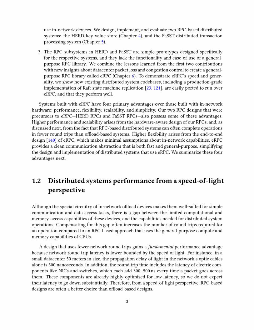
Although the special circuitry of in-network o�oad devices makes them well-suited for simplecommunication and data access tasks, there is a gap between the limited computational andmemory-access capabilities of these devices, and the capabilities needed for distributed systemoperations. Compensating for this gap often increases the number of round trips required foran operation compared to an RPC-based approach that uses the general-purpose compute andmemory capabilities of CPUs.
A design that uses fewer network round trips gains a fundamental performance advantagebecause network round trip latency is lower-bounded by the speed of light. For instance, in asmall datacenter 50 meters in size, the propagation delay of light in the network’s optic cablesalone is 500 nanoseconds. In addition, the round trip time includes the latency of electric com-ponents like NICs and switches, which each add 300–500 ns every time a packet goes acrossthem. These components are already highly optimized for low latency, so we do not expecttheir latency to go down substantially. Therefore, from a speed-of-light perspective, RPC-baseddesigns are often a better choice than o�oad-based designs.
3
Client ServerNIC CPU DRAM
(b) CPU-bypass hash table access with RDMA
RDMA-read bucket
RDMA-read value
Client ServerNIC CPU DRAM
(a) Hash table access with RPCs
RPC request
RPC response
Read bucket &value from DRAM
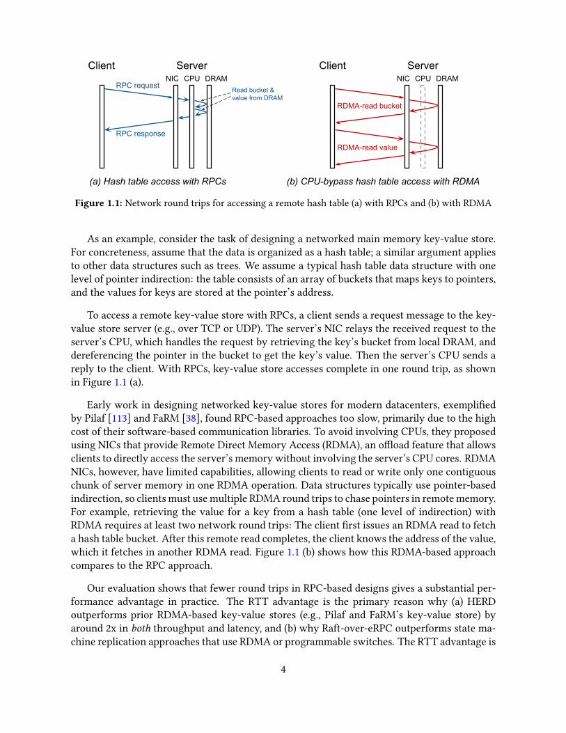
Figure 1.1: Network round trips for accessing a remote hash table (a) with RPCs and (b) with RDMA
As an example, consider the task of designing a networked main memory key-value store.For concreteness, assume that the data is organized as a hash table; a similar argument appliesto other data structures such as trees. We assume a typical hash table data structure with onelevel of pointer indirection: the table consists of an array of buckets that maps keys to pointers,and the values for keys are stored at the pointer’s address.
To access a remote key-value store with RPCs, a client sends a request message to the key-value store server (e.g., over TCP or UDP). The server’s NIC relays the received request to theserver’s CPU, which handles the request by retrieving the key’s bucket from local DRAM, anddereferencing the pointer in the bucket to get the key’s value. Then the server’s CPU sends areply to the client. With RPCs, key-value store accesses complete in one round trip, as shownin Figure 1.1 (a).
Early work in designing networked key-value stores for modern datacenters, exempli�edby Pilaf [113] and FaRM [38], found RPC-based approaches too slow, primarily due to the highcost of their software-based communication libraries. To avoid involving CPUs, they proposedusing NICs that provide Remote Direct Memory Access (RDMA), an o�oad feature that allowsclients to directly access the server’s memory without involving the server’s CPU cores. RDMANICs, however, have limited capabilities, allowing clients to read or write only one contiguouschunk of server memory in one RDMA operation. Data structures typically use pointer-basedindirection, so clients must use multiple RDMA round trips to chase pointers in remote memory.For example, retrieving the value for a key from a hash table (one level of indirection) withRDMA requires at least two network round trips: The client �rst issues an RDMA read to fetcha hash table bucket. After this remote read completes, the client knows the address of the value,which it fetches in another RDMA read. Figure 1.1 (b) shows how this RDMA-based approachcompares to the RPC approach.
Our evaluation shows that fewer round trips in RPC-based designs gives a substantial per-formance advantage in practice. The RTT advantage is the primary reason why (a) HERDoutperforms prior RDMA-based key-value stores (e.g., Pilaf and FaRM’s key-value store) byaround 2x in both throughput and latency, and (b) why Raft-over-eRPC outperforms state ma-chine replication approaches that use RDMA or programmable switches. The RTT advantage is
4

also one of the reasons why FaSST outperforms RDMA-based transaction processing systems.
To emphasize that round trip ampli�cation is a common drawback of o�oad-based ap-proaches, we list below more some examples of round trip ampli�cation in common distributedsystem operations.
• Reading and locking a remote object, a primitive used in applications such as dis-tributed transaction processing, requires two round trips with RDMA: one RDMA atomicoperation to acquire a lock, and another to read the object data [154, 159]. In our FaSSTtransaction processing system (Chapter 5), completing both steps requires one RTT withan RPC.
• Appending an entry to a remote log with RDMA may require two round trips: one towrite an entry to the log, and one to increment the log’s tail pointer [129]. Such loggingrequires one RPC to an active server, as in our Raft-over-eRPC system (Section 6.6.1).
• Replicating an object in the memory of a group of programmable network switchesoften necessitates using serial, chain replication [151] due to the limited compute andmemory resources on such switches [76]. RPC-based approaches can instead use parallelprimary-backup replication, which has lower latency with four or more replicas.
1.3 An end-to-end design for high �exibility
The most advanced RPC library presented in this dissertation, eRPC (Chapter 6), follows anend-to-end design, meaning that the network provides only lossy datagram forwarding, and allother functionality is contained in software running on end-host CPUs. The network need notprovide more sophisticated capabilities such as losslessness, in-order packet delivery, and con-gestion control, or in-network o�oad devices. Our decision to not rely on special in-networkcapabilities has its roots in classic networks and systems design principles.
David Clark noted in 1988 [27] that making minimal assumptions about the capabilities ofthe underlying network helps maximize the range of network designs across which the Internetprotocols can function. Similar bene�ts arise in datacenter networks; these bene�ts, however,must be weighed against the potential cost of eliding possible optimization from placing addi-tional capabilities in network hardware. Unlike the Internet, datacenters run in a more homo-geneous context. The large number of recent systems that depend on in-network o�oads, suchas RDMA, lossless networks, programmable NICs, and programmable switches might suggestthat, in datacenters, the performance advantages outweigh the reduction in �exibility.
The end-to-end arguments by Saltzer et al. [140] o�er guidance about whether to implementfunctionality at a low level or a high level. They note that resisting function inclusion in thelow-level core of a system is often the correct design choice [135], and that “Using performance tojustify placing functions in a low-level subsystemmust be done carefully. Sometimes, by examiningthe problem thoroughly, the same or better performance can be achieved at the high level.” Ourexperience with designing communication software for modern datacenters is in line with this
5

quote: end-to-end systems built with eRPC are faster than or competitive with systems thatrely on in-network capabilities, while being more �exible.
The higher �exibility of eRPC’s end-to-end design manifests in three broad ways.
1. Variety of networks. eRPC requires only basic datagram forwarding, so it works inall datacenter networks. In contrast, designs that rely on special in-network capabilitiesare limited to datacenters that support such capabilities. At the time of writing, suchcapabilities are deployed in only a small fraction of datacenters. Adopting designs thatdepend critically on network functionality can also tie developers’ hands in the future.For example, current RDMA deployments require the network’s link layer to preventpacket loss, which precludes transport-level mechanisms that depend on lost packets asa signal (e.g., packet loss–based congestion control).
2. Data access. Applications often require data access in ways that are handled easily by aCPU, but are ine�cient, cumbersome, or unsupported in in-network devices. A CPU mayperform any required sequence of memory reads and writes, use cheap atomic instruc-tions to manage concurrent access to memory, or use instruction fences and cache line�ushes to provide ordering or durability in hosts with non-volatile memory. In-networkdevices restrict memory access patterns (e.g., RDMA allows only one contiguous accessper round trip). These devices typically attach to the host over the PCI Express (PCIe)bus, and, as a result, lack �rst-class support for concurrency control, memory ordering,and durability.
3. Network protocol innovation. Network transports for datacenters evolve rapidly. Forexample, new and improved schemes for congestion control and packet retransmissionare invented frequently. Implementing these transport functionalities in software allowsadapting to new innovations quickly, because it is much easier to change end-host soft-ware than modifying network devices. Transport layer functionalities are sometimesimplemented in NICs or switches to get high performance and to free up CPU cycles, butmodi�cations might require support from the network vendor [55, 165]. eRPC uses newinsights about datacenter congestion control and packet loss to show that a full-�edgedsoftware transport can be fast, disproving the commonly-held belief that o�oading thetransport to network hardware is necessary for performance.
1.4 Scalability: A silicon power consumption argument
Distributed systems in modern datacenters may run on thousands of hosts. The large scaleof communication imposes a scalability challenge at every host that is best handled by CPUs,whose high-capacity and sophisticated memory subsystem (i.e., CPU caches and DRAM) pro-vides fast access to the large amount of communication state in such settings. In contrast,network o�oad devices such as NICs and FPGAs have less capable memory subsystems foreconomic reasons, reducing their scalability.
6

Providing a full-�edged network transport typically requires a connection-oriented design,in which the host maintains per-connection state for every pair of communicating peers. This isbecause connections are a natural way to providing reliable packet delivery, congestion control,and encryption; the state size for each connection is typically a few hundred bytes. For exam-ple, in Mellanox’s current implementation of RDMA transport in their NICs, each connectionrequires around 375 B of state.
The combined memory footprint of connection state at one host can be several tens ofmegabytes. A high-end host in a modern datacenter today has around 100 CPU cores. Tocommunicate with 1000 peers in the datacenter without sharing connections among CPU cores,the host creates 100 × 1000 = 100,000 connections. The combined state for these connectionsis around 100000 × 375 bytes, which equals 37.5 MB. This memory footprint is manageablein CPUs, which have tens of megabytes of cache, and fast DRAM to serve cache misses. Inaddition, memory latency hiding techniques in hardware and software can reduce the penaltyof cache misses. Transport layer o�oad devices like NICs and FPGAs have only a few megabytesof cache, resulting in frequent cache misses at large scale. These cache misses are expensivebecause they are typically served from their host CPU’s memory subsystem over the slow PCIebus.
Caches on o�oad devices are unlikely to become much larger in the near future becausethese devices are expected to consume little power. In order to stay power-e�cient, they ded-icate little die area to caches, which are power-hungry. In general, the utility of acceleratorsoften comes from their low cost and power e�ciency. Transport accelerators with more cachewill be more expensive and power-hungry, and therefore might be less useful. Compared tomore powerful CPUs, making transport accelerators much more powerful appeals to a smallerdemographic of users and applications, and pins resources (e.g., cost and energy) an in�exibleway.
1.5 A fast and general-purpose design for simplicity
Squeezing the best performance out of modern, high-speed datacenter networks has meantpainstaking specialization that breaks down the abstraction barriers between software andhardware layers. This is because existing datacenter networking software options sacri�ce per-formance or generality, preventing unmodi�ed applications from using the network e�ciently.On the one extreme, low-level high-speed packet I/O libraries such as DPDK [37] are fast, butlack features required by real applications, such as support for multi-packet messages, packetretransmission, and congestion control. Fully-general networking stacks such as mTCP [74]and IX [15] allow legacy sockets-based applications to run unmodi�ed. Unfortunately, theyleave substantial performance on the table, especially for small messages. For example, with64 B RPC requests, one server core running can handle only 1.5 million requests per secondwith IX, and over 10 million requests per second with eRPC.
By providing both high speed and a general-purpose feature set su�cient for real applica-
7
tions, eRPC allows existing distributed system codebases to run at near-network speeds, withlittle or no modi�cations to their source code. The explosion of co-designed distributed systemsthat depend on niche network technologies stemmed from the lack of networking software thatprovides both speed and generality. eRPC preserves a modular networking abstraction, per-mitting reuse of existing software and developer e�ort, including data structures, distributedprotocols, programmer hours, tests, formal speci�cations, and feature sets. Co-designing dis-tributed systems with the network breaks abstraction boundaries between components, andprevents such reuse.
Our work helps achieve more robust designs by making existing systems faster in thecon�nes of current hardware, instead of breaking abstraction boundaries (e.g., the hardware-software boundary, or the boundary between systems software and application software) inpursuit of performance. Our designs aid datacenter-level simplicity, because they don’t havemuch entanglement between modules.
1.6 Evolution of our RPC designs
The research that went into this thesis was conducted over six years, in which we developeda series of RPC designs—HERD RPCs, FaSST RPCs, and eRPC. Our initial designs targetedspeci�c applications, and they had special network requirements, until we arrived at eRPC,which is the focus of this thesis. HERD RPCs require an RDMA-capable network, and they workbest in asymmetric client-server applications with many clients and few servers. FaSST RPCsrequire a network with a lossless link layer, which, in theory, is a less stringent requirement thanan RDMA-capable network. (In practice, however, datacenters with lossless networks usuallyalso support RDMA.) FaSST RPCs are specialized for symmetric online transaction processingapplications, where every host acts as both a client and server.
Our main contribution in eRPC is an e�cient design that does not depend on network fea-tures, nor is specialized for a particular application. HERD RPCs and FaSST RPCs help providecontext for evaluating eRPC’s performance relative to more specialized designs: we show thateRPC provides the �exibility and simplicity of an end-to-end, general-purpose design for a smallperformance penalty.
The evolution from HERD RPCs, to FaSST RPCs, and �nally to eRPC is marked by a decreas-ing reliance on special network features, made possible by our own improved understandingof datacenter network hardware capabilities. For example, we used RDMA writes for requestmessages in HERD because we believed that using traditional packet I/O for receiving requestsnecessarily adds PCIe overhead at the server. In eRPC, we show how modern NIC features allowavoiding much of this PCIe overhead for traditional packet I/O. Similarly, we used a losslessnetwork in FaSST because we were concerned that packet loss in lossy networks would crippleRPC performance. In eRPC, we show how with a little assistance from the software transportlayer, switch bu�ers in lossy datacenters are su�cient to prevent most packet loss.
8
Chapter 2
Background
In this chapter, we discuss relevant background for high-performance distributed systems inmodern datacenter networks. We �rst describe state-of-the-art datacenter networking hard-ware and software. We review recent datacenter technology advances that permit inter-hostcommunication with only a few microseconds of latency, and close to a hundred gigabits persecond of bandwidth. Next, we discuss the class of communication-intensive applications thatwe target in our work, which spend a large portion of their time in the communication subsys-tem. We review examples and use cases of such applications, their cluster-level scale, and theircommunication and computation requirements.
2.1 Modern datacenter networks
A decade ago, fast networks were exclusive to High-Performance Computing (HPC) cluster in-terconnects, such as In�niBand, or Cray’s Aries and Gemini interconnects. Commodity Ethernet-based datacenter networks were slow, which made it challenging to build fast communication-intensive distributed systems. For example, a replicated database that provides strong con-sistency guarantees requires that a host coordinate with remote replicas before committinga database transaction. Before the recent adoption of fast Ethernet networks in datacenters,such coordination was often prohibitively expensive, leading database designers to adopt weakconsistency guarantees.
Over the last decade, commodity Ethernet-based datacenter networks have caught up withHPC interconnects. Their latency improved from hundreds of microseconds to single-digitmicroseconds, and bandwidth improved from 1 Gbps to 100 Gbps. A combination of faster net-working hardware and software drove this improvement. On the hardware side, vendors cre-ated Ethernet switches and NICs that add lower latency and handle higher-bandwidth links. Onthe software side, datacenter operators deployed userspace networking stacks that bypass theoperating system kernel’s heavyweight network stack, and eliminate expensive system callsand interrupts from the performance-critical datapath.
9

Ethernet NICTo ToR PCIe bus PCIe
controllerCore 1
Core N
Multi-core CPU
MemorycontrollerDRAM
Figure 2.1: Hardware components of a host in a datacenter
We cannot simply re-purpose an existing HPC communication library for datacenter work-loads and get high performance. HPC clusters typically use an implementation of the MessagePassing Interface (MPI) speci�cation for communication, which are currently ill-suited for dat-acenter workloads, for three main reasons. First, on commodity datacenter networks that lackRDMA support, MPI implementations use the kernel’s TCP stack for reliability and congestioncontrol, and are therefore slower than even kernel TCP. Second, MPI designers typically targetworkloads with di�erent requirements than datacenter workloads. For example, the messagesize in HPC workloads is much larger: the average point-to-point MPI message size in HPCworkloads ranges from a few kilobytes to hundreds of kilobytes [158]. In contrast, as we dis-cuss later in Section 2.2.4, datacenter applications require high performance for messages assmall as a few tens of bytes. MPI implementations perform poorly for such workloads. Third,MPI is usually slow even when HPC interconnects are available. Quoting a recent paper thatseeks to remedy MPI’s high overhead [131], with authors from several supercomputing centers,and NIC and MPI vendors: “MPI is often criticized as being a heavyweight runtime system that canadd signi�cant overhead, particularly for applications that need very �ne-grained communicationon fast networks, ...”
2.1.1 Datacenter network hardware
Datacenter networks connect tens of thousands of hosts in a datacenter. Figure 2.1 shows thehigh-level hardware architecture of a host in an Internet datacenter, deployed in companies suchas Microsoft, Google, and Facebook. Each host contains one or a few multicore CPUs, each with∼20 CPU cores, and a few hundreds of gigabytes of DRAM. The CPUs in one host are attachedto one 10–100 gigabit Ethernet NIC at the host using a 32—128 Gbps PCIe link. Hosts dedicatedto particular applications such as machine learning may have application-speci�c acceleratorslike GPUs (not shown in the �gure). A few tens of such hosts are organized in a rack, and a fewtens of racks comprise a pod. A typical large datacenter contains many such pods.
Figure 2.2 shows how the hosts in a datacenter are typically interconnected using a fat-treetopology [5]. The NICs of all hosts in one rack connect to a top-of-rack (ToR) switch. ToRswitches in one pod connect to leaf switches in the pod. Leaf switches from all pods in thedatacenter connect to spine switches.
10
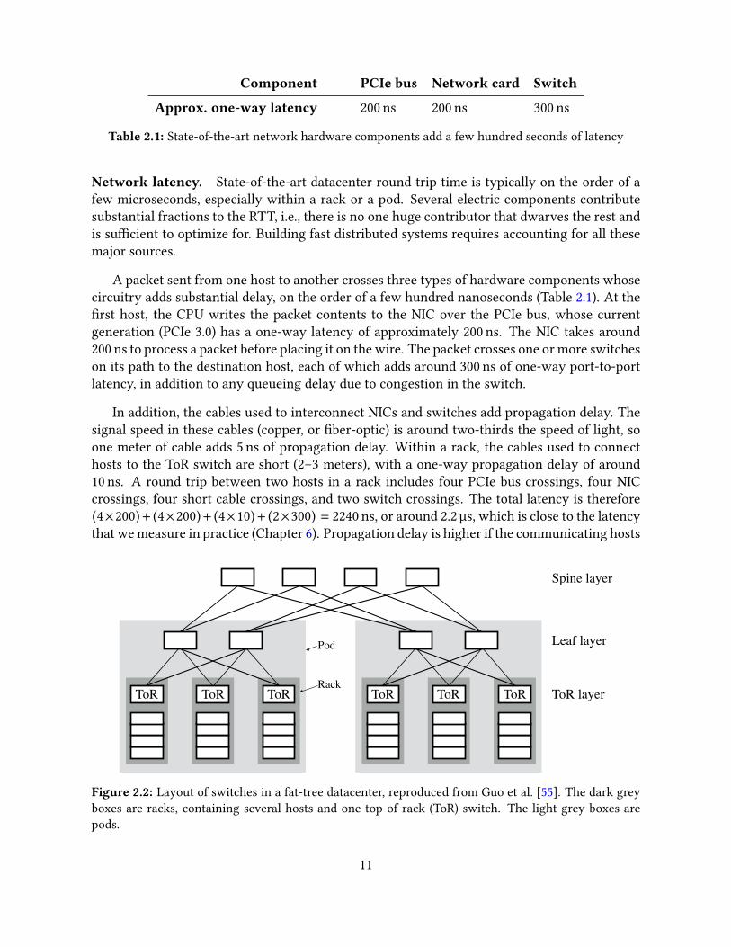
Component PCIe bus Network card Switch
Approx. one-way latency 200 ns 200 ns 300 ns
Table 2.1: State-of-the-art network hardware components add a few hundred seconds of latency
Network latency. State-of-the-art datacenter round trip time is typically on the order of afew microseconds, especially within a rack or a pod. Several electric components contributesubstantial fractions to the RTT, i.e., there is no one huge contributor that dwarves the rest andis su�cient to optimize for. Building fast distributed systems requires accounting for all thesemajor sources.
A packet sent from one host to another crosses three types of hardware components whosecircuitry adds substantial delay, on the order of a few hundred nanoseconds (Table 2.1). At the�rst host, the CPU writes the packet contents to the NIC over the PCIe bus, whose currentgeneration (PCIe 3.0) has a one-way latency of approximately 200 ns. The NIC takes around200 ns to process a packet before placing it on the wire. The packet crosses one or more switcheson its path to the destination host, each of which adds around 300 ns of one-way port-to-portlatency, in addition to any queueing delay due to congestion in the switch.
In addition, the cables used to interconnect NICs and switches add propagation delay. Thesignal speed in these cables (copper, or �ber-optic) is around two-thirds the speed of light, soone meter of cable adds 5 ns of propagation delay. Within a rack, the cables used to connecthosts to the ToR switch are short (2–3 meters), with a one-way propagation delay of around10 ns. A round trip between two hosts in a rack includes four PCIe bus crossings, four NICcrossings, four short cable crossings, and two switch crossings. The total latency is therefore(4×200)+ (4×200)+ (4×10)+ (2×300) = 2240 ns, or around 2.2 µs, which is close to the latencythat we measure in practice (Chapter 6). Propagation delay is higher if the communicating hosts
ToRToRToR ToR layer
Leaf layer
Spine layer
ToRToRToRRack
Pod
Figure 2.2: Layout of switches in a fat-tree datacenter, reproduced from Guo et al. [55]. The dark greyboxes are racks, containing several hosts and one top-of-rack (ToR) switch. The light grey boxes arepods.
11

are in di�erent pods. The links between leaf switches and spine switches are ∼200-meter �beroptic cables [55], which add around 1 µs of one-way propagation delay.
Network bandwidth and message rate. Hosts within a rack can communicate at the fullbandwidth of their ToR links. To keep network costs low, operators typically oversubscribeToR switches, meaning that these switches have higher cumulative bandwidth to the serversin their rack than to the leaf switches. Oversubscription ratios ranging from as 2:1 and 6:1are commonly used. Each host can send and receive tens of millions of packets per second. A100 Gbps Ethernet link can theoretically transmit ∼150 million packets per second (Mpps), andsuch message rates are attainable in practice. Therefore, the end-host networking subsystemshould ideally be capable of handling over a hundred million packets per second.
2.1.2 Userspace networking
State-of-the-art datacenter network hardware allows hosts to communicate at 100 Gbps, sendover a hundred million packets per second, and complete round trips in a few microseconds.Bringing the advantages of fast network hardware to application software, however, requiredchanging the way in which applications access the network. Historically, the kernel managedapplications’ access to the network via the sockets system call application programming in-terface (API) that uses the kernel’s heavyweight network stack. Despite continual e�orts toimprove OS network stacks, the improvements did not keep up with improvements in networkspeed.
As 10 Gbps Ethernet gained widespread adoption in Internet datacenters, the overhead ofheavyweight kernel stacks started limiting application performance. Rizzo [137] showed that,in 2012, an application running on the FreeBSD kernel took around 1000 ns to transmit oneUDP packet using the sendto() system call. Communication-intensive applications that relyon kernel stacks spend a large percentage of their CPU cycles in the kernel, not executinguseful application logic, e.g., 80% in the popular lighttp HTTP server [74], and 75% in a popularmemcached in-memory key-value store [15].
For more CPU-e�cient networking, kernel-bypass networking—a widely-used approach inHPC—is gaining traction in Internet datacenters. Kernel-bypass network stacks run entirely inuserspace, reducing or eliminating three sources of overhead that are present in kernel stacks:
1. System call overhead. With kernel stacks, applications must use system calls to ac-cess the NIC. System calls require expensive user-to-kernel context switches, whosepreviously-high ∼50 ns cost recently increased to ∼200 ns due to kernel page table isola-tion patches for the Meltdown [98] security vulnerability [91].
With userspace stacks, applications can send and receive packets without kernel in-volvement, except during initial setup. The initial setup consists of mapping the NIC’spacket I/O queues and registers into application memory. After this is done, packets canbe sent or received with cheap memory-mapped I/O instructions. Modern NICs typically
12
support multiple isolated queues, allowing safe access from multiple processes.
2. Interrupt overhead. With kernel stacks, the NIC generates interrupts on receivingpackets. Although interrupts can be coalesced, in the worst case, one interrupt is gen-erated per received packet. The CPU cycle cost of handling an interrupt with currentkernels is approximately 2500 ns [78].
Userspace stacks typically disable interrupts, and check for received packets by pollingthe NIC’s memory-mapped packet receive queue. This results in high performance whenpackets are being regularly received, at the expense of wasted CPU cycles during periodswhen few packets are received. Although our work relies on busy-polling, recent workby Ka�es et al. [78] and Ousterhout et al. [123] shows that it may be possible to achievethe best of both worlds, i.e., the performance of busy-polling during high load, and thee�ciency of interrupts during low load.
3. Hardware-generality. General-purpose OS stacks support a wide variety of networktypes (e.g., WiFi, wide-area networks, Bluetooth, etc) with vastly di�erent bandwidth,latency, routing, and packet loss characteristics. They run on a range of computers, fromembedded devices with limited CPU and memory, to high-end datacenter servers. Thisgenerality comes at the cost of performance.
Userspace stacks typically aim to support only high-speed datacenter networks, sothey may sacri�ce hardware-generality for performance. For example, it is safe to assumethat datacenter servers have su�cient DRAM to pre-allocate memory for packet bu�ers,whereas this assumption might not work well in embedded devices.
The end result from these three classes of optimization is that userspace stacks such asDPDK [37] can handle 20–30 million packets per second with one CPU core, over an orderof magnitude higher than OS stacks. With a few CPU cores, multi-threaded applications canhandle the 150 million packets per second supported by a 100 Gbps link.
High-speed packet I/O alone is rarely su�cient for building real applications. A full trans-port layer provides a more convenient abstraction by hiding the details of message fragmenta-tion, packet retransmission, congestion control, and bu�er memory management. Applicationsthat use plain packets sometimes choose to embed some transport-related functionality at theapplication level [119], but doing so breaks modularity, thereby preventing code reuse, and in-creasing complexity. eRPC provides a modular transport layer with all these features, leavingfew reasons for re-implementing transport functionality at the application level.
2.1.3 In-network o�loads for distributed systems
Several types of devices or technologies may be deployed in datacenter networks to speed updistributed systems by shifting data processing or transport-related tasks away from CPUs. We
13

next provide an overview of four such technologies that are currently seeing use—RDMA, loss-less networks, programmable NICs, and programmable switches—along with their strengthsand shortcomings when used in distributed systems.
2.1.3.1 Remote Direct Memory Access
RDMA, by de�nition, is a NIC hardware feature that allows a client host to directly read or writethe memory of a remote server host without involving the CPU at the remote host. RDMA hasbeen a common feature in HPC clusters for decades, starting from the Virtual Interface Archi-tecture (VIA) [41]. Today, supercomputers typically use special RDMA-capable interconnects(e.g., In�niBand [64], or Cray’s Aries interconnect [7]), which have their own suite of layer-1through layer-4 protocols. In Internet datacenters, however, IP and Ethernet are the de-factolayer-2 and layer-3 protocols. To allow using RDMA in such datacenters, network vendors cre-ated a new protocol called RDMA over Converged Ethernet (RoCE) derived from In�niBand torun on IP-routed Ethernet.
To distinguish from RoCE, we refer to non-RDMA providing Ethernet networks as classicalEthernet. At the time of writing, RDMA NICs and classical Ethernet NICs are priced similarly.
RDMA NICs, including RoCE NICs from vendors such as Mellanox [108] and Broadcom [22],typically provide two features in addition to server CPU bypass that reduce CPU cycles spentin communication at both the client and the server host. They provide kernel bypass, meaningthat the operating system kernel at either host is involved only during initial RDMA setup. TheNICs also implement the transport layer in hardware, including reliable and ordered packetdelivery, and congestion control.
To expose a region of server memory for RDMA from clients, an application at the serverregisters a region of memory with the RDMA NIC. A client that wishes to access this regionestablishes an RDMA connection with the server over an out-of-band communication channel.During this handshake, the client application receives the remote region’s virtual address anda security key from the server. In addition, NICs at both the server and the client allocate andinitialize transport contexts for the connection.
To write a local bu�er into the server’s memory, the client application issues an RDMA-write work request to its NIC, specifying the connection, the local bu�er’s address, and thedestination address the server. The client’s NIC fetches the local bu�er over PCIe using DirectMemory Access (DMA) and sends it to the server. On receiving the bu�er, the server’s NICDMA-writes it to the destination address. On completing the transfer, the client’s NIC DMA-writes a completion entry to the application. Transport engines in the client and server NIChandle message fragmentation and reassembly, acknowledgments, retransmission, and conges-tion control. Only the client’s CPU spends cycles throughout the RDMA write: �rst for writinga small work request to the NIC, and then for processing the completion. No unnecessary copiesof the bu�er are made, resulting in a zero-copy transfer.
We provide a more detailed description of RDMA’s di�erent transports and capabilities in
14

Chapter 3. The In�niBand architecture speci�cation [64] is a comprehensive reference.
Strengths. RDMA improves speed and e�ciency primarily when used for regular memoryreads and writes that access one contiguous region of remote memory per round trip. Forexample, virtual machine migration requires transferring gigabytes of data between DRAM oftwo hosts. RDMA allows such a transfer at peak network bandwidth and near-zero CPU cycles.Another example is memory disaggregation, wherein hosts expose parts of their DRAM overthe network. Remote hosts whose memory requirement exceeds their memory capacity canuse the exposed DRAM as slow memory or swap space [4, 52].
Shortcomings. RDMA has three primary shortcomings that reduce its usefulness in dis-tributed systems. First, the limited �exibility of RDMA forces designers to add ine�ciencyor complexity to the system’s design in order to compensate for the lack of rich operations.For example, as discussed in Section 1.2, because RDMA is limited to one remote memory ac-cess per round trip, using RDMA for remote data structure access necessitates additional roundtrips per access. Similarly, RDMA’s lack of �rst-class support for concurrency control and per-sistence forces a cumbersome design in systems that deal with concurrent data modi�cationsand non-volatile memory, respectively.
Second, the per-connection RDMA communication state is kept in small on-NIC caches,reducing scalability (Section 1.4). Third, current RDMA NICs require a lossless link layer (dis-cussed next), which is challenging to deploy at datacenter scale, limiting RDMA’s deploymentto only a few companies, such as Microsoft [55].
2.1.3.2 Lossless networks
Commodity datacenter networks are lossy, meaning that switches regularly drop packets due tobu�er over�ow caused by congestion. Lossless packet delivery is a link-layer feature that pre-vents congestion-based packet drops. On Ethernet networks, if Priority Flow Control (PFC) [63]is enabled, a link’s receiver prevents its bu�er from over�owing by sending a pause frame to thelink’s sender before the bu�er over�ows. HPC interconnects such as In�niBand typically usecredit-based link-level �ow control [64], in which the link’s sender transmits data only if thereceiver has previously indicated su�cient bu�er room, i.e., the sender has su�cient credits.
Strengths. Lossless link layers have two primary advantages. First, they simplify the trans-port layer’s implementation. Since packets are lost extremely rarely (e.g., during network hard-ware failures), the transport layer may keep its packet loss recovery logic on a slow path, sim-plifying the fast path; such simpli�cation can be necessary for an e�cient hardware implemen-tation. For example, RDMA NICs often exclude packet loss recovery logic from their transportengine ASIC circuits, instead implementing the recovery logic in slow �rmware [165].
Second, lossless link layers potentially reduce tail latency for applications by reducing re-transmission timeouts experienced by end hosts, which add a large amount of tail latency. Endhosts typically must wait for tens of milliseconds before retransmitting a packet that they sus-pect to be lost. This is because datacenter switches can add several milliseconds of queueing
15

delay. For example, a 100 GbE Broadcom Trident 3 switch can queue up to 32 MB of data be-hind a congested egress port, which takes 2.6 ms to drain. Because there may be several suchcongested switches in the network, avoiding spurious retransmissions that increase conges-tion requires a 10–100 millisecond retransmission timeout. With a lossless link layer, there areno retransmissions in the absence of hardware failures, avoiding the retransmission timeoutproblem altogether.
Shortcomings. Link layer losslessness comes with several fundamental problems. Cyclicbu�er dependencies can cause deadlocks, causing the network to come to a halt. Because entirelinks are paused, packets taking an uncongested path may get stuck due to a paused, causinghead-of-line blocking. Switch con�guration becomes more complex, due to bu�er reservationand congestion marking parameters that depend on bu�er reservation [165]. Mittal et al. [116]discuss these problems in detail. In our experience, most Ethernet datacenter operators areunwilling to deploy PFC due to these problems. Since current RDMA NICs depend on a losslessnetwork for good performance, these operators also do not deploy RDMA. Some datacenteroperators, including Microsoft [55], have deployed PFC at scale to support RDMA.
2.1.3.3 Programmable NICs
Adding new capabilities into NICs is one path towards high-speed distributed systems. Cur-rent NICs span a wide spectrum of functionality. One the one extreme, the average NIC in adatacenter is a simple interface for sending and receiving datagrams on the network; our workshows that it is possible to build fast distributed systems with such NICs alone. In the middleof the spectrum, RDMA-capable NICs provide a �xed set of additional capabilities: one remotememory access per round trip, and a hardware transport layer. Programmable NICs are at theother extreme of high functionality, providing near general-purpose processing inside the NIC.
Programmable NICs add some DRAM and a programmable chip—either an FPGA or a mul-ticore CPU with simple, low-power cores—to the NIC board, in addition to the �xed-functionNIC ASIC. The NIC’s programmable chip can handle requests received at the host using on-NICprocessing and memory, and send a response without involving the CPU at the host. Examplesof FPGA-based programmable NICs include Microsoft’s Azure SmartNIC [47] and Mellanox’sInnova [109]. Examples of multicore CPU–based programmable NICs include Amazon’s Ni-tro [11], Mellanox’s BlueField [107], Marvell’s LiquidIO [106], and Netronome’s Agilio [118].The CPUs in these NICs use either commodity ARM or MIPS cores, or proprietary cores spe-cialized for packet processing.
Strengths. The deployment of programmable NICs accelerated because of their applicabilityto fast network virtualization in cloud providers such as Microsoft Azure and Amazon WebServices [11, 47]. In cloud datacenters, virtual machines (VMs) need fast networking, but theiraccess to the physical network must be mediated by a programmable layer that is trusted bythe datacenter operator. Traditionally, this was done in software by the hypervisor. Pushingnetwork access mediation to NIC hardware improves performance by allowing VMs direct net-work access without expensive VM exits to the hypervisor.
16

When used as devices to handle distributed system operations (e.g., in-memory hash tableaccesses), programmable NICs typically provision dedicated hardware resources for the appli-cation. As a result, they may provide more predictable latency than handling the operations ona host CPU, which is typically shared by many applications. However, the bene�t of latencypredictability is reduced by other sources of latency variation. Request latency will be higherduring network congestion, regardless of whether the end-host device handling the operationis a programmable NIC or a CPU. In addition, the client issuing the operation is typically soft-ware running on a CPU, so handling the operation in the server’s NIC eliminates only part ofthe latency variation caused by using CPUs.
Shortcomings. For remote data structure access, programmable NICs o�er a seemingly bet-ter alternative to RDMA because they can perform multiple memory accesses while processinga request. However, host memory accesses from a programmable NIC go over the slow PCIebus, which has higher latency (∼500 ns) than the host CPU’s connection to its DRAM (∼80 ns).1As a result, programmable NICs su�er from latency ampli�cation due to multiple PCIe roundtrips, similar to RDMA’s latency ampli�cation over the datacenter network. In addition, similarto RDMA NICs, programmable NICs lack �rst-class support for concurrency, memory ordering,and durability.
2.1.3.4 Programmable switches
Historically, network switches were �xed-function: they examined a �xed set of header �elds(e.g., IP address), and implemented a �xed set of actions on packets (e.g., forwarding or drop-ping a packet, or decrementing a packet’s time-to-live �eld). The use of Software-De�ned Net-working in datacenters demanded programmable switches that can process arbitrary header�elds, and perform more general-purpose actions [20]. Such switches, such as Barefoot’s To�noswitches [146] that are programmed in the P4 switch programming language [125], are cur-rently being deployed in some datacenters.
Packets arriving at a programmable switch’s port are queued into the port’s ingress pipelinein the switch ASIC. The pipeline’s programmable parser extracts the packet’s header, and passesit through a series of programmable match-action tables. Both the parser and the match-actiontables are speci�ed by the switch program (e.g., the P4 program). Each match-action stageexamines a �xed set of �elds from the packet header. If the �elds match an entry in the stage’stable, the switch takes a simple action speci�ed by the entry (e.g., modify a header �eld, orincrement an in-switch counter). After ingress processing, the header is routed to an egressport by the switch’s crossbar. The egress port’s pipeline may include more match-action stagesbefore the packet is transmitted.
Strengths. Currently, the primary use cases of programmable switches in industry are innetwork management, e.g., improving network visibility through telemetry and real-time mea-surements, and improving network reliability by eliminating unneeded features that are typ-ically included in �xed-function switches [13]. These use cases are orthogonal to the class of
1Although programmable NICs have some on-board DRAM, most of the host’s DRAM is connected to the CPU.
17
distributed systems studied in this thesis.
By virtue of their placement in the network, programmable switches o�er a unique abilityto reduce the number of network hops in a distributed protocol, improving latency [92, 93, 130].For example, in Paxos and other related leader-based state machine replication protocols [85],completing a replication request requires four network hops when replicas are failure-free.The client �rst sends its request to the leader replica, which assigns a sequence number to therequest, and forwards it to follower replicas. Each follower replies to the leader, which replies tothe client after collecting replies from followers. Li et al. [92] show how using a programmableswitch as the leader can reduce the number of e�ective network hops to two.
Shortcomings. The limited computational and memory �exibility of the match-action pro-gramming model leads to complex designs that shoehorn application logic into switches. Thereare also open challenges that must be solved before developers can safely use programmableswitches in applications beyond network management. First, it is unclear how stateful algo-rithms in recent in-switch applications [76, 92, 93] handle in-switch parallelism. Today’s pro-grammable switches use multiple independent match-action pipelines to satisfy bandwidth de-mands. There is no support for inter-pipeline state sharing or concurrency control becausethe need to run pipelines at line rate precludes such heavyweight functionalities. Second, howcan we safely provide control over shared network switches to application developers? For in-stance, how should we safely and e�ectively share switch SRAM among packet bu�ering, andmemory allocated to di�erent in-switch applications?
2.2 Communication-intensive distributed applications
Core services in datacenters are typically distributed systems, which run on anywhere betweena few hosts to thousands of hosts. This section �rst gives an overview of three examples of thetypes of communication-intensive applications that we target in this dissertation. Then, wedescribe two common workload characteristics across the three applications that challenge thecommunication subsystem: small messages, and short per-message processing.
2.2.1 Main-memory key-value stores
Main memory–based key-value stores and caches are widespread in large-scale Internet ser-vices. They are used both as primary stores (e.g., Redis [134]), and as caches in front of backend,persistent databases (e.g., Memcached [112]). At their most basic level, these systems export thetraditional key-value interface, with GET, PUT, and DELETE calls. The key-value items are parti-tioned across hosts, typically using a scheme such as consistent hashing [82] with key hashes.Internally, they use a variety of data structures to provide fast, memory-e�cient access to theirunderlying data (e.g., hash table or tree-based indexes).
Distributed in-memory key-value stores are an important building block for large-scale web
18

services. For example, Facebook’s Memcached deployment consists of thousands of machinesand acts as an object cache for trillions of data items [119].
2.2.2 Distributed transaction processing
Distributed transactional data stores with ACID guarantees (Atomicity, Durability, Isolation,and Durability) are the primary persistent data stores in datacenters. Examples include MySQLat Facebook, Google’s BigTable, and Microsoft’s SQL server [25, 119]. A transaction is a se-quence of reads and writes to items in the data store, delimited by transaction begin and endcommands. A distributed transaction processing system with ACID guarantees provides a pow-erful programming abstraction for designing distributed systems such as object stores and on-line transaction processing (OLTP) systems. Such a system provides the illusion of one central-ized database, in which transactions commit durably in sequence.
In the past, with slow networks and storage technologies, distributed databases sacri�cedeither transaction support, or weakened transaction consistency guarantees [39]. For exam-ple, BigTable provides only single-row transactions, and Amazon’s Dynamo [34] provides onlyeventual consistency instead of strong consistency. Recently, by Dragojević et al. [39] showedthat with the availability of fast networks and non-volatile memory in datacenters, distributedtransactions with strong consistency guarantees can achieve good performance, supportingmillions of distributed transactions per second with around 100 hosts.
Modern Internet services handle such transaction rates in practice. For example, Amazonreports that their Aurora database handled 148 billion transactions over two days worldwide [8].This transaction rate corresponds to 0.85 million transactions per second on average. Due toskew in transaction rate, it is reasonable to expect that their database handled many millionsof transactions per second during some periods of high activity.
2.2.3 State machine replication
State machine replication (SMR) is used to build highly available services, such as metadatastores or lock servers. An SMR service consists of a group of server hosts that receive commandsfrom clients. SMR protocols ensure that each server executes the same sequence of commands,and that the service remains available if servers fail. Paxos [85] and Raft [121] are widely-used SMR protocols that take a leader-based approach: Absent failures, the SMR replicas havea stable leader to which clients send commands; if the leader fails, the remaining Raft serverselect a new one. The leader appends the command to replicas’ logs, and it replies to the clientafter receiving acknowledgments from a majority of replicas.
Despite its seeming simplicity, SMR is di�cult to design and implement correctly [59]: theprotocol must have a speci�cation and a proof (e.g., in TLA+), and the implementation mustadhere to the speci�cation. A fast and general-purpose communication library like eRPC allowsusing an existing well-tested SMR implementation, avoiding the high complexity and cost of
19

re-implementing or redesigning an SMR system from scratch for new in-network hardwaretechnologies.
2.2.4 Common application workload characteristics
Communication-intensive applications, including the three examples discussed above, imposetwo challenging requirements on the communication subsystem.
1. Small messages. These systems handle primarily small messages, ranging from tensto a few hundred bytes. In Facebook’s Memcached deployment [9], the most frequentlyaccessed cache pool (“USR”), has keys up to 21 B, and virtually all values are 2 B. Inaddition, 90% of all cache space is allocated to values smaller than 500 B. In the industry-standard TPC-C benchmark for transactional databases, the entries in each database tableare smaller than 320 B [148]. SMR systems are typically used for serving small locks andmetadata objects.
2. Short per-message application processing. Messages in communication-intensivesystems require tens of nanoseconds to a few microseconds of application-level process-ing. Accessing a main-memory hash table or a tree-based data structure takes only tens tohundreds of nanoseconds [89]. An RPC in a distributed database or SMR system typicallyrequires either a cheap access to a main-memory key-value store, or persisting a transac-tion’s update log record. With the availability of non-volatile memory technologies suchas Intel’s DC Persistent Memory [67], the latter requires only hundreds of nanosecondsto a few microseconds.
It is challenging to design a communication library that performs well for small messagesand short per-message application-level processing. Doing so requires attention to numeroussubtle factors, such as user-kernel crossings, PCIe overheads, NIC architecture details, CPUcache misses, bu�er management, etc. These factors are less important for workloads withlarge messages or high per-message processing. For these workloads, performance dependsprimarily on simpler factors. They are likely to be bottlenecked by network bandwidth orapplication-level processing, or the number of times (typically zero or one) large packet bu�ersare copied,
2.3 Evaluation clusters
To demonstrate that the techniques, optimizations, and system designs presented in this dis-sertation are general and not dependent on particular hardware platforms, we evaluate themon several di�erent clusters spanning a wide range of hardware technologies. Table 2.2 lists thespeci�cations of these clusters. Notably, the NICs used in our evaluation span almost a decadeof hardware, and they include both In�niBand and Ethernet. We name each cluster using anabbreviation of the cluster’s NIC model.
20

Cluster name CX CX3 CIB CX4 CX5
Number of nodes 10 200 11 100 8Network type In�niBand In�niBand In�niBand Ethernet EthernetMellanox switch In�niScale IV SX6036 SX6036 SN2410/SN2100 SX1036
CPU model Opteron 8354 E5-2450 E5-2683 v3 E5-2640 v4 E5-2697 v3Core count, frequency 4c, 2.2 GHz 8c, 2.1 GHz 14c, 2.0 GHz 10c, 2.4 GHz 14c, 2.6 GHz
NIC release date 2008 2011 2012 2014 2016Mellanox NIC ConnectX ConnectX-3 Connect-IB ConnectX-4 Lx ConnectX-5NIC ports and speed 1x 20 Gbps 1x 56 Gbps 2x 56 Gbps 1x 25 Gbps 2x 40 GbpsPCIe link PCIe 2.0 x82 PCIe 3.0 x8 PCIe 3.0 x16 PCIe 3.0 x8 PCIe 3.0 x16
Table 2.2: Evaluation clusters used in our work. CX, CX3, and CX4 are public clusters that are partof NSF PRObE, Emulab, and CloudLab, respectively [51, 136, 156]. CIB and CX5 are private clusters atNetApp and Carnegie Mellon University, respectively. CPU models with names starting with “E5” areIntel Xeon CPUs with two-way Hyper-threading.
2.4 Open-source code
The source code for all systems and experiments presented in this dissertation is available on-line.
• Chapter 3: https://github.com/efficient/rdma_bench
• Chapter 4: https://github.com/efficient/HERD
• Chapter 5: https://github.com/efficient/fasst
• Chapter 6: https://github.com/erpc-io/eRPC
21

“There are many highly respected motives which may lead peopleto prosecute research, but three which are much more importantthan the rest. The �rst (without which the rest must come tonothing) is intellectual curiosity, desire to know the truth. ”
G. H. Hardy
Chapter 3
Guidelines for use of modern high-speed NICs
Designing fast end-to-end communication software for datacenter networks requires usingNICs e�ciently. Modern NICs are complex devices, with sophisticated in-NIC computationand memory subsystems, including packet processing engines, DMA engines, and memoriesfor various data structures and metadata. Combined, these subsystems provide a wide arrayof knobs that govern performance of even basic Ethernet packet I/O. In addition, most currentNICs go beyond packet I/O to provide a hardware transport layer and Remote Direct MemoryAccess.
This chapter covers two contributions. First, a central question for our work is choosing theright NIC primitives and knob con�gurations for RPCs. This chapter describes the experimentsand evaluation results that back up our choice of involving CPUs in distributed systems, andthe design of our RPC subsystems. For example, we illustrate why it is bene�cial to use plainpacket I/O instead of RDMA writes for implementing RPCs.
The second contribution is a set of high-level guidelines aimed at providing researchersand developers with a roadmap through the large design space of NIC primitives and knobs,without necessarily becoming NIC gurus. A lesson from our work is that low-level hardwarefactors, such as individual PCIe messages and NIC hardware architecture, are surprisingly im-portant for fast communication. Reasoning about these factors is challenging, in part becausedoing so has traditionally required expensive or con�dential resources, such as PCIe analyzersand proprietary NIC manuals. As a result, these factors have received little attention from theresearch community. This chapter aims to �ll this gap.
These guidelines are backed by an open-source set of measurement tools (https://github.com/efficient/rdma_bench) for evaluating and optimizing the most important system fac-tors that a�ect performance when using NICs. This chapter evaluates the e�ectiveness of ourguidelines and optimizations using simple microbenchmarks. In later chapters, we show howthe RPC subsystems in HERD, FaSST, and eRPC bene�t from these guidelines. In those chapters,we refer back to our guidelines using the Guideline label.
We divide our guidelines into two broad classes.
22

1. We show that reducing tra�c over the PCIe link mitigates PCIe bandwidth and latencybottlenecks that arise frequently in high-speed communication. During packet I/O, inaddition to packet payloads, metadata such as PCIe bus headers, bu�er descriptors andcompletions are also transferred over the PCIe bus. These metadata are not strictly neces-sary for application functionality. We present and evaluate several optimizations aimedat reducing PCIe tra�c.
2. Second, we show that modern NICs’ parallel architecture o�ers both opportunities andpitfalls. Today’s datacenter NICs are composed of multiple processing units (PUs), suchas packet processing engines and DMA engines. We develop techniques for exploitingintra-NIC parallelism, and show how and when doing so can be bene�cial. We also showhow NIC primitives that require synchronization among PUs, such as atomic operations,can reduce performance.
We begin our journey into modern NICs with an overview of the PCIe interconnect andNIC operation.
3.1 A review of PCI Express
PCI Express is a point-to-point interconnect used to connect CPUs to peripheral devices, suchas NICs, GPUs, storage drives, and FPGAs. PCIe endpoints typically communicate by writingto each other’s memory over the PCIe link, using PCIe protocol packets [128]. As shown inFigure 2.1, the NIC at each host in a datacenter is attached to the PCIe controller of the host’sCPU, which is located on the same die as the CPU cores. The PCIe controller reads and writesthe CPU’s L3 cache to service the NIC’s memory access requests.
The current widely-deployed PCIe generation is PCIe 3.0, which provides approximately1 GB/s per lane, unidirectionally. Datacenter NICs typically use 8 or 16 PCIe 3.0 lanes (i.e.,PCIe 3.0 x8 or PCIe 3.0 x16 links, respectively), for a total of 8 GB/s or 16 GB/s, respectively. Wehave evaluated the e�ectiveness of our PCIe-related guidelines on both the previous PCIe 2.0generation, and PCIe 3.0. We expect our guidelines to also apply to hosts with the upcomingPCIe 4.0 generation, which doubles the per-lane bandwidth from PCIe 3.0 to 2 GB/s. This isbecause upcoming 200 GbE NICs stress the bandwidth of even PCIe 4.0 x16, so reducing PCIeuse remains important. In addition, several of our optimizations target other characteristics ofPCIe, such as latency, PCIe header overhead, and CPU cycle use. These characteristics remainlargely unchanged with PCIe generation updates.
3.1.1 PCIe headers
Reasoning about PCIe performance in communication-intensive datacenter applications re-quires understanding the overhead of PCIe packet headers. This is because such applicationsgenerate primarily small PCIe packets, in which the size of PCIe headers is comparable to the
23

PCIe 2.0 PCIe 3.0
Per-lane bandwidth 500 MB/s 985 MB/sPCIe transaction request header size 24 B 26 B
PCIe transaction completion header size 20 B 22 B
Table 3.1: Lane bandwidth and header sizes for PCIe 2.0 and PCIe 3.0.
size of useful application payload. The PCIe packets are small for two reasons. First, as dis-cussed in Section 2.2, the requests and responses in our target applications are primarily small,ranging from tens to a few hundred bytes. Second, CPUs write to NICs using memory mappedI/O (discussed in the next section), which generates PCIe packets with cacheline-sized, 64 Bpayloads.
PCIe is a layered protocol, consisting of physical, link, and transaction layers. The totalheader size is 20–26 B, depending on the PCIe generation and the transaction type. Table 3.1lists the bandwidth and header overhead for the PCIe generations in our clusters.
CPU-NIC communication generates three types of PCIe transaction layer packets (TLPs):read requests, read completions, and write requests (there is no transaction-layer completionresponse for a write). For example, the NIC may write data to the CPU’s memory by sending awrite request transaction packet to the CPU.
3.1.2 Memory-mapped I/O and Direct Memory Access
Communication between CPUs and NICs uses one of two methods, with di�erent latency, CPUcycle use, and bandwidth tradeo�s. CPUs access NIC memory using memory-mapped I/O(MMIO). NICs access CPU memory using Direct Memory Access (DMA). A NIC typically is-sues DMAs while servicing a request received from the network, or in response to an MMIOwrite received from its host CPU. For example, CPUs typically initiate packet transmission bywriting a packet’s address to the NIC; the NIC then DMA-reads the packet, and sends it on thenetwork. Understanding MMIO and DMA along with their performance tradeo�s is importantfor designing fast communication software.
Memory-mapped I/O. To use MMIO, the application �rst uses the NIC device driver to mapa portion of the NIC’s memory into the application’s address space. Then, the application canwrite to the NIC’s memory with store instructions. To avoid generating a PCIe write for eachstore instruction, CPUs use an optimization called “write combining,” which combines storesto generate cache line–sized PCIe transactions.
An MMIO write is the lowest-latency method for a CPU to transfer data to the NIC. However,it consumes CPU cycles, and incurs high PCIe header overhead because all PCIe packets haveonly cacheline-sized payloads. In several situations, the DMA approach reduces CPU cyclesand bandwidth overhead.
24

0
200
400
600
800
0 64 128 192 256 320 384 448 512By
tes
trans
ferre
d
x (bytes)
DMA
MMIO
Figure 3.1: CPU-to-NIC PCIe tra�c for an x-byte transfer with DMA and MMIO, assuming PCIe 3.0and Crc = 128 bytes.
DirectMemoryAccess. NICs have DMA engines that can access the CPU’s memory subsys-tem without involving CPU cores. To transfer data to the NIC, the CPU writes just the bu�er’sdescriptor (i.e., its address and length) using to the NIC using MMIO. The NIC then DMA-readsthe bu�er. This results in a CPU-e�cient transfer, because CPU cycles are consumed only forthe small descriptor MMIO, not for the entire bu�er.
DMA is often more bandwidth-e�cient than MMIO because DMA transfers are not re-stricted to cache line units. For example, a NIC can write up to 4 kB to the CPU’s memory inone DMA write packet. Large DMA reads, however, are split into smaller packets. To read fromthe CPU’s memory, a NIC sends a PCIe read request TLP to the CPU, whose PCIe controllerreplies with one or more read completion TLPs. A read completion TLP with a payload largerthan the CPU’s read completion combining size (Crc) is split into multiple completions. We usethe CX3, CIB, and CX clusters (Table 2.2) for measurements in this chapter. Crc is 128 B for CX3and CIB [70, 71]; we assume 128 B for the CX cluster because we did not �nd a publicly-availablevalue for its CPU.
A DMA read always uses less CPU-to-NIC PCIe bandwidth than an equal-sized MMIO write;Figure 3.1 shows an analytical comparison. With MMIO, the bu�er transfer uses TLPs withexactly 64 B payloads, which is ine�cient compared to read completion TLPs with variable-sized payloads up to Crc bytes in size. This factor is important, and we show how it a�ectsperformance of higher-layer protocols in the subsequent sections.
3.2 How modern NICs work
The performance of communication software depends on how it uses the NIC. This section pro-vides an overview of modern NICs’ operation that is common to both the traditional Ethernetpacket interface and the RDMA interface. The next section reviews RDMA.
NICs provide a simple abstraction of multiple transmit and receive (TX and RX) queues.
25

Each queue consists of multiple slots that contain descriptors. To initiate packet transmission orreception, the NIC driver creates descriptors in the TX or RX queue resident in CPU memory,and transfers them to the NIC using either MMIO writes or DMA reads. We discuss the tradeo�sof these two methods in Section 3.6.2. On completing the work for a TX or RX descriptor, theNIC signals completion by DMA-writing a completion entry (CQE) to a completion queue (CQ)associated with the TX or RX queue.
Descriptor format and size is speci�c to the NIC vendor and model, and depends on severalfactors, including the operation type, transport, optimization �ags, and operation initiationmethod. A minimal TX queue descriptor contains the address and length of a packet in hostmemory; the NIC fetches the packet using a DMA read, and places it on the wire. A minimalRX queue descriptor contains the address and length of a bu�er in host memory where the nextpacket received by the NIC for that queue is DMA-written to. More sophisticated descriptorsmay be larger. For example, the TX descriptor may include the payload for small packets, whichreduces latency by avoiding the DMA read used to fetch the payload.
Note that, in RDMA parlance, queue descriptors are also called Work Queue Elements(WQEs). We use the more general term descriptors to refer to both WQEs and Ethernet RX/TXqueue descriptors.
3.3 RDMA terminology
Support for RDMA in datacenters is on the rise. At the time of writing, most major NIC ven-dors, including Mellanox, Intel, and Broadcom provide RDMA support in their state-of-the-artmodels. Understanding RDMA performance is therefore important for designing high-speedcommunication for distributed systems. While we chose to not rely on RDMA support in our�nal RPC design, we include guidelines and measurements for RDMA NICs in this chapter.Section 2.1.3.1 provides high-level background on RDMA. We provide more relevant detailsbelow.
3.3.1 RDMA verbs
Userspace programs access RDMA-capable NICs directly using functions called RDMA verbs.While there are several types of verbs, the ones most relevant to this work are RDMA reads,RDMA writes, RDMA atomics, sends, and receives. We abbreviate these verbs as READ, WRITE,ATOMIC, SEND, and RECV, respectively.
READs, WRITEs, and ATOMICs operate directly on remote memory, bypassing the remoteCPU. Because these verbs involve only the initiator’s CPU, they are termed one-sided. In con-trast, SENDs and RECVs are called two-sided verbs, because both the initiator’s CPU and theremote CPU is involved. A SEND’s payload is written to a remote memory address that is spec-i�ed by the remote CPU in a pre-posted RECV. This is similar to packet I/O semantics o�ered
26

Server(requester)
WRITE, UC
READ, RC
SEND, UD
a) Outbound verbs b) Inbound verbs
Clients(requester)
WRITE, UC
READ, RC
RECV, UD
Clients(responder)
Server(responder)
Figure 3.2: Inbound and outbound verbs at the server.
by non-RDMA NICs, except that the data transferred by an RDMA SEND or RECV may bemultiple packets in size. SEND/RECV verbs are also called messaging verbs.
3.3.2 RDMA queue pairs
Verbs are posted by applications to RDMA queues. Queues always exist in pairs: a send queueand a receive queue form a queue pair (QP). Each queue pair has an associated completionqueue (CQ), which the NIC �lls in upon completion of verb execution. RDMA-enabled hostspost operations to QPs using a userspace verbs provider library, such as libibverbs in Linux.READs, WRITEs, ATOMICs, and SENDs are posted to the send queue, and RECVs are postedto the receive queue.
We call the host initiating a verb the requester and the destination host the responder. Forsome verbs, the responder does not actually send a response. We distinguish between inboundand outbound verbs because their performance di�ers signi�cantly: READs, WRITEs, ATOM-ICs, and SENDs are outbound at the requester and inbound at the responder; RECVs are alwaysinbound. Figure 3.2 depicts inbound and outbound verbs pictorially.
3.3.3 RDMA transport types
RDMA transports can be connected or unconnected. A connected transport requires a hard-ware connection between two queue pairs that communicate exclusively with each other. Cur-rent RDMA implementations support two main types of connected transports: Reliable Con-nected (RC) and Unreliable Connected (UC). There is no acknowledgment of packet receptionin UC; packets can be lost and the a�ected message can be dropped. As UC does not generateACK/NAK packets, it causes less network tra�c than RC.
In an unconnected transport, one queue pair can communicate with any number of otherqueue pairs. Current implementations provide only one unconnected transport: UnreliableDatagram (UD), which is similar to plain packet I/O in classical Ethernet NICs. Because RDMANICs maintain state for each active queue in their internal SRAM, datagram transports can scalebetter for applications with a one-to-many communication pattern.
Some transport types support only a subset of the available verbs. Table 3.2 lists the verbs
27

Reliable Connected Unreliable Connected Unreliable Datagram
Two-sided SEND/RECV 3 3 3
RDMA writes 3 3 7
RDMA reads 3 7 7
Table 3.2: Operations supported by each RDMA transport type
supported by each transport type. UC does not support READs because READs are implicitlyacknowledged by the RDMA read response. UD does not support one-sided RDMA verbs.
RDMA networks, including In�niBand and RoCE, typically employ lossless link-level �owcontrol (Section 2.1.3.2). Even with unreliable transports (UC/UD), packets are never lost due toswitch bu�er over�ows. RDMA networks lose packets due to bit errors on the wire and hardwarefailures, which are extremely rare.
3.4 Preface to the guidelines
We believe that these guidelines apply broadly to the kinds of NIC hardware currently deployedin datacenters. Although the measurements reported in this chapter are for In�niBand NICs(running both datagram packet I/O and RDMA verbs), the guidelines are applicable to anyPCIe-based NIC with an internally-parallel architecture—two requirements that are generallysatis�ed by high-speed NICs at the time of writing. NICs in today’s datacenters are PCIe cards;some vendors are beginning to integrate NICs on-die or on-package [66, 68, 69], but these NICsstill communicate with the CPU’s PCIe controller using the PCIe protocol, and are less powerfulthan discrete NICs. The performance requirements of high-speed NICs generally necessitatesinternal parallelism with multiple processing units [58].
Importantly, we have found that several of our guidelines that bene�t In�niBand’s UD trans-port also apply to packet I/O with classical Ethernet NICs, which eRPC targets. This is becausepacket I/O on Ethernet NICs works similarly at the PCIe and NIC level to In�niBand’s UD trans-port. Therefore, the two communication modes have similar performance characteristics, andbene�t similarly from our optimizations.
We now present our guidelines. For each guideline (e.g., reduce CPU-initiated MMIOs),we provide insight on both how to determine whether this guideline is relevant (e.g., if anapplication can issue multiple concurrent RPCs, it can transmit them with one MMIO). Weprovide speci�c optimizations to realize each guideline, and discuss the guideline’s e�ectivenessand limitations.
28
3.5 Guidelines for NICs with transport-layer o�load
Some NICs, such as RDMA NICs and TCP o�oad engines, implement a reliable hardware-based transport layer that guarantees in-order message delivery with zero CPU use. Usingsuch a transport is a seemingly attractive choice for implementing RPCs. For example, RPC de-signs for RDMA-capable NICs typically use RDMA’s Reliable Connected transport [38, 113, 154].However, our research suggests that such transports are not the best match for RPCs, and thatusing unreliable datagrams with the transport layer implemented in software provides higherperformance, scalability, and �exibility. These bene�ts arise from two fundamental advantagesof the latter approach: the ability to piggyback transport layer acknowledgments (ACKs) onRPC responses, and higher scalability from no per-connection on-NIC state.
3.5.1 Prefer application-level ACKs over transport-level ACKs
Reliable hardware transports use explicit, transport-level acknowledgments. However, for RPCs,it is possible to use fewer network messages by using a request’s response as an implicit ac-knowledgment for the request. This implicit-ACK optimization is not new, originating withBirrell and Nelson’s seminal paper on RPCs [18]. Our contribution here is in showing the valueof foregoing CPU cycle savings from o�oading reliability to NIC hardware in favor of reducingnetwork messages.
With implicit ACKs, the client sends the RPC request over an unreliable transport, such asUDP on Ethernet networks, or RDMA’s Unreliable Datagram or Unreliable Connected trans-port; the server replies using a second message over the unreliable transport. Doing so savesNIC and network resources consumed by explicit acknowledgments, improving performance.Although ACK packets are small, their size and in-NIC processing requirement is comparable totypical RPC packet size in several datacenter applications (Section 2.2). For short, single-packetRPCs, implicit-ACKs reduce the number of packets per RPC from four to two.
E�ectiveness. In Section 4.3.2.2, we show that using implicit application-level ACKs insteadof RDMA’s transport-level ACKs improves the performance of HERD’s RPC design by 13%. Allthree RPC designs presented in this thesis (i.e., HERD RPCs, FaSST RPCs, and eRPC) use implicitACKs.
Using an unreliable transport does not mean high packet loss: First, on lossless networks,link-level �ow control prevents congestion-based packet drops regardless of the transport layer(Section 2.1.3.2). Therefore, unreliable transports get near-reliable packet delivery without pay-ing the cost at the transport level. In addition to link-level �ow control, modern high-speednetworks often employ forward error correction and link-layer retransmission for bit-error re-covery, which bene�ts unreliable transports, too. Combined, these two techniques make packetloss extremely rare. In our experiments on a 70-node cluster with a lossless In�niBand network,we observed no packet loss during a 50 petabyte data transfer with Unreliable Datagrams (Chap-ter 5).
29

Second, on lossy networks, we show in Chapter 6 that simple end-host software techniquesare su�cient to prevent most packet drops. The key insight is that the bandwidth-delay product(BDP) in modern datacenter networks is much smaller than the bu�ering capacity of datacenterswitches. Restricting each �ow to one BDP of outstanding data e�ectively prevents packet lossduring even heavy congestion, while allowing �ows to achieve peak network bandwidth.
Limitations. An RPC server can send a response with the implicit ACK only after complet-ing request processing, which involves running a user-provided request handler function. Asa result, the ACK may get delayed arbitrarily. Congestion control protocols typically extractinformation about network congestion from ACKs, such as such as Explicit Congestion Noti-�cation marks [49] or RTT [21, 88, 115]. Delayed feedback degrades the quality of congestioncontrol. In our target applications (Section 2.2), request handlers are typically short-running,allowing prompt congestion feedback in most cases. Congestion control protocols can handle amodest amount of noise and delay [165], which we believe is su�cient to handle delayed ACKsfrom a small fraction of long-running RPC handlers in our target workloads. However, implicitACKs may not work well for other applications in which most RPC handlers are long-running(e.g., requiring tens of microseconds per request).
While the implicit-ACK optimization works well for RPCs, it does not work well for othercommon communication patterns that lack a response on which ACKs may be piggybacked,such as message passing, or RPC chains [141]. (In an RPC chain, a client sends a request messageto a server, which performs some computation, and forwards the message along a chain ofservers. The �nal server in the chain replies to the client.) Note that our other guidelines arenot speci�c to the request-reply communication pattern, and they work well for other patterns.
3.5.2 Avoid storing connection state on NICs
NICs that provide a reliable transport layer implement hardware-based one-to-one connectionsbetween communicating entities. A small, on-NIC SRAM (Section 1.4) caches connection state,backed by the CPU’s memory subsystem. At large scale, when the number of connections atthe host exceeds the NIC’s cache capacity, the NIC serves cache misses by fetching connectionstate from the CPU’s memory subsystem over the slow PCIe bus, reducing performance.
Transport-layer o�oad NICs, including most RDMA NICs and TCP o�oad engines, usea connection-oriented design because connections are the natural implementation vehicle fortransport-layer features such as end-to-end reliability and congestion control. RDMA’s connection-oriented goes back to the Virtual Interface Architecture (VIA), which is a popular model foruser-level, zero-copy networking [41], and forms the basis of current commodity RDMA im-plementations such as In�niBand and RoCE. VIA architects made the design decision to useconnections to simplify NIC implementation. In Mellanox’s RDMA implementation, each con-nection requires around 375 B of state. TCP o�oad engines typically use 128–256 B of stateper connection [31, 46]. NICs have only a ∼2 MB of SRAM, preventing scaling to over a fewthousand connections.
A software-based transport layer approaches can scale better by (1) using stateless data-
30
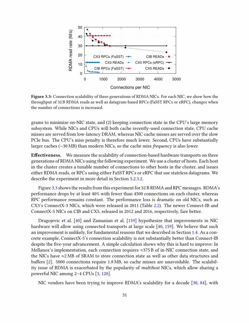
0
10
20
30
40
50
0 1000 2000 3000 4000 5000
RD
MA
read
rate
(M/s
)
Connections per NIC
CX3 RPCs (FaSST)CX3 READs
CIB RPCs (FaSST)
CIB READsCX5 RPCs (eRPC)
CX5 READs
Figure 3.3: Connection scalability of three generations of RDMA NICs. For each NIC, we show how thethroughput of 32 B RDMA reads as well as datagram-based RPCs (FaSST RPCs or eRPC), changes whenthe number of connections is increased.
grams to minimize on-NIC state, and (2) keeping connection state in the CPU’s large memorysubsystem. While NICs and CPUs will both cache recently-used connection state, CPU cachemisses are served from low-latency DRAM, whereas NIC cache misses are served over the slowPCIe bus. The CPU’s miss penalty is therefore much lower. Second, CPUs have substantiallylarger caches (∼30 MB) than modern NICs, so the cache miss frequency is also lower.
E�ectiveness. We measure the scalability of connection-based hardware transports on threegenerations of RDMA NICs using the following experiment. We use a cluster of hosts. Each hostin the cluster creates a tunable number of connections to other hosts in the cluster, and issueseither RDMA reads, or RPCs using either FaSST RPCs or eRPC that use stateless datagrams. Wedescribe the experiment in more detail in Section 5.2.3.2.
Figure 3.3 shows the results from this experiment for 32 B RDMA and RPC messages. RDMA’sperformance drops by at least 40% with fewer than 4500 connections on each cluster, whereasRPC performance remains constant. The performance loss is dramatic on old NICs, such asCX3’s ConnectX-3 NICs, which were released in 2011 (Table 2.2). The newer Connect-IB andConnectX-5 NICs on CIB and CX5, released in 2012 and 2016, respectively, fare better.
Dragojevic et al. [40] and Zamanian et al. [159] hypothesize that improvements in NIChardware will allow using connected transports at large scale [40, 159]. We believe that suchan improvement is unlikely, for fundamental reasons that we described in Section 1.4. As a con-crete example, ConnectX-5’s connection scalability is not substantially better than Connect-IBdespite the �ve-year advancement. A simple calculation shows why this is hard to improve: InMellanox’s implementation, each connection requires ≈375 B of in-NIC connection state, andthe NICs have ≈2 MB of SRAM to store connection state as well as other data structures andbu�ers [2]. 5000 connections require 1.8 MB, so cache misses are unavoidable. The scalabil-ity issue of RDMA is exacerbated by the popularity of multihost NICs, which allow sharing apowerful NIC among 2–4 CPUs [3, 120].
NIC vendors have been trying to improve RDMA’s scalability for a decade [30, 84], with
31
techniques that do not involve putting more SRAM in NICs. We describe later in Section 5.6.1why these techniques do not map well to our target workloads.
Among our three RPC designs presented in this thesis, only HERD RPCs require in-NICconnection state, and they do so in a fashion that allows a HERD server to handle a largenumber of clients: the server uses NIC-managed connections only for receiving requests overRDMA writes. The key insight is that these connections have a small NIC footprint becausethey carry only inbound tra�c. In our later RPC designs (i.e., FaSST RPCs and eRPC), we createdmechanisms to preserve the performance of HERD’s RDMA write–based requests while usingonly scalable datagrams.
Limitations. Although all commodity implementations of RDMA use a connection-orienteddesign, there are niche speci�cations and implementations for connectionless RDMA. Portalsis one such speci�cation [14]; the Bull eXascale Interconnect [35] is a recent hardware imple-mentation of Portals, currently available only to HPC customers. The availability of scalableone-sided RDMA may reduce the at-scale performance advantage of our RPC-based designscompared to RDMA-based designs. However, RPC-based designs will still retain their advan-tage of fewer round trips, and higher �exibility and simplicity. Further, it is likely that RPC im-plementations that use scalable one-sided RDMA writes will provide even better performancethan our current datagram-based designs.
3.6 Reduce PCIe tra�c
3.6.1 Measurement method: PCIe counters on commodity CPUs
Reasoning about and optimizing PCIe tra�c requires understanding and modeling the PCIeinteraction between NICs and CPUs. Doing so is challenging because a precise PCIe analysis re-quires di�cult-to-obtain resources, including expensive PCIe analyzers, and proprietary/con�dentialNICs manuals. We contribute a method for PCIe analysis that does not require these resources:we use PCIe counters available on modern CPUs to create a nearly complete model of NICPCIe behavior. Our analysis primarily uses counters for DMA reads and DMA writes, namedPCIeRdCur PCIeItoM, respectively, on Intel CPUs. For each counter, the number of capturedevents per second is its counter rate.
CPU PCIe counters are imprecise: The CPU counts PCIe events by intercepting cache line–level activity between the PCIe controller and the L3 cache, so the counters can miss somecritical information. For example, the counters indicate two PCIe DMA reads when the NICreads a four-byte chunk straddling two cache lines.
32

1, 21, 2
0 64Doorbell
a) WQE-by-MMIO method b) Doorbell method
128 192 2560 64 128 192 256
2211
a) Descriptor-MMIO
Figure 3.4: The Descriptor-MMIO and Doorbell methods for transferring two WRs (shaded) spanningtwo cache lines. Arrows represent PCIe transactions. Red (thin) arrows are MMIO writes; the blue (thick)arrow are DMA reads. Arrows are marked with descriptor numbers; arrow width represents transactionsize.
3.6.2 Reduce CPU-initiated MMIOs
MMIO writes are relatively expensive for the CPU because they require �ushing the writebu�ers, and using memory barriers for ordering. Reducing MMIOs, or replacing them withmore CPU- and bandwidth-e�cient DMAs can improve both CPU e�ciency and NIC through-put. CPUs initiate network operations by sending a message to the NIC via MMIO. The messagecan either contain the new work requests, or it can refer to the new descriptors by using infor-mation such as the address of the last descriptors. This works because queue descriptors arelaid out contiguously in host memory.
In the �rst case, the CPU uses 64 B write-combined MMIOs to transfer the descriptors tothe NIC. In the second case, the NIC reads the descriptors using one or more DMAs. We makethe simplifying assumption that the NIC reads all new descriptors in one DMA, which we havefound to work well in practice. In reality, NICs may read one or more descriptors per DMA,depending on the NIC’s proprietary prefetching logic. We refer to these methods as Descriptor-MMIO and Doorbell, respectively. Di�erent NIC technologies have di�erent terms for thesetwo methods. For example, Mellanox uses “BlueFlame” and “Doorbell,” and Intel Omni-PathArchitecture uses “Programmed I/O send” and “SDMA,” respectively. Figure 3.4 summarizesthese two methods. The Descriptor-MMIO method optimizes for low latency and is typicallythe default method in userspace NIC drivers.
The size of TX descriptors is vendor-speci�c, and it depends on several factors. For example,with RDMA NICs, the TX descriptor size depends on the transport. In Mellanox’s implementa-tion, as of 2019, descriptors for RC and UD transports’ TX queues have 36 B and 68 B headers,respectively. UD transport’s descriptor is larger because it includes network routing informa-tion. For RC transport, routing information for the connection is cached inside the NIC.
Terminology and default assumptions. To discuss the impact on CPU and PCIe use ofthe optimizations in this chapter, we consider transferring N descriptors of size D bytes fromthe CPU to the NIC. We denote the per-lane bandwidth, request header size, and completionheader size of PCIe 3.0 by Pbw , Pr , and Pc , respectively. As our study focuses on small messages,descriptors include inlined payloads by default (Section 3.6.3.1).
Figure 3.5 summarizes two optimizations for reducing MMIOs—Doorbell batching and de-scriptor shrinking—introduced below.
33

1WQE MMIO
CQE DMA
1
22
1
2
CPU NIC
+Unsignaled: CQEs are dropped; reduces PCIe txns, NIC processing
+Doorbell batching: Multiple WQEs DMA-ed in one transaction; reduces CPU use, PCIe txns
1, 2Dbell MMIO
WQE DMA1, 2
CPU NIC
+WQE shrinking via header-only SEND: Uses 4B header field for application data; reduces PCIe bandwidth use(256 B DMA)
1, 2Dbell MMIO
WQE DMA1, 2
CPU NIC
(128 B DMA)
Figure 3.5: Optimizations for issuing two 4 B UD SENDs. A UD SEND descriptor spans two cache lineson Mellanox NICs because of the 68 B header; we shrink it to one cache line by using a 4 B header �eldfor payload. Arrow notation follows Figure 3.4.
3.6.2.1 Doorbell batching
If an application can issue multiple descriptors to a TX queue, it can use one Doorbell MMIO forthe batch of descriptors. Doorbell batching reduces CPU-generated MMIOs from N ∗ dD/64ewith per-descriptor MMIO to one. Because DMA reads are more bandwidth-e�cient thanMMIOs, doorbell batching also reduces PCIe bandwidth use. For example, with N = 10 andD = 128 and PCIe 3.0, descriptor transfer generates 1534 B of PCIe tra�c, whereas Descriptor-MMIO generates 1800 B.1
Batching is relevant only to the Doorbell mode. In the Descriptor-MMIO mode, a batcheddescriptor transfer is identical to a sequence of individual descriptor transfers. Therefore, weuse the more general but shorter term batching to refer to Doorbell batching. In this chapter,we use Descriptor-MMIO for non-batched operations, and Doorbell for batched operations.However, when batching is enabled but the available batch size is one, we use Descriptor-MMIO.This is because Doorbell provides little CPU savings for transferring a single small descriptor,and uses an extra PCIe transaction.
E�ectiveness. Batching is highly e�ective for sending datagrams. Figure 3.6 shows thethroughput and PCIe bandwidth limit of batched and non-batched UD SENDs on CIB. Weuse one server to issue SENDs to multiple client machines. When batching is enabled, we usebatches of size 16 (i.e., the NIC DMA-reads 16 descriptors per Doorbell). Otherwise, the CPUwrites the descriptors with the Descriptor-MMIO method. We use as many cores as requiredto maximize throughput. Batching improves peak SEND throughput by 27% from 80 millionoperations/s (Mops) to 101.6 Mops.
With batching, throughput is limited by DMA bandwidth: Every DMA completion of sizeCrc bytes has a PCIe completion header of size Pc bytes (22 B, Table 3.1), leading to 13443 MB/s ofuseful DMA read bandwidth on CIB. Because UD SEND descriptors with non-empty payloads
1Let us denote the doorbell size (8 bytes) by d . The total data transmitted from CPU to NIC with the Descriptor-MMIO method is Tbf = 10 ∗ (d128/64e ∗ (64 + Pr )) bytes. Assuming Crc = 128, the Doorbell method transmitsTdb = (d+Pr )+ (10∗ (128+Pc )) bytes. We ignore the PCIe link layer tra�c since it is small compared to transaction-layer tra�c: it is common to assume two link-layer packets (one �ow control update and one acknowledgment,both 8 B) per 4-5 PCIe TLPs [150], making the link-layer overhead less than 5%. Substituting d = 8, Pr = 26, andPc = 22 (Table 3.1) gives Tbf = 1800, and Tdb = 1534.
34

0
20
40
60
80
100
120
0 50 100 150 200 250R
ate
(milli
ons/
sec)
Payload size (bytes)
PCIe limit (B=16)SEND (B=16)
PCIe limit (B=1)SEND (B=1)
Figure 3.6: Peak batched and non-batched UD SEND throughput on CIB, with batch size B. Dotted linesshow corresponding PCIe limits.
span at least two cache lines on CIB NICs, the maximum descriptor transfer rate is 13443/128 =105 million/s, which is within 5% of our achieved throughput. We attribute the di�erence tolink- and physical-layer PCIe overheads.
Non-batched throughput is limited by MMIO bandwidth. The write-combining MMIO rateon CIB is (16 ∗ Pbw )/(64+ Pr ) = 175 million cache lines/s. Because our descriptors span at least2 cache lines, the upper limit for throughput is 87.5 Mops. This is within 10% of our achieved80 Mops.
Limitations. Batching is primarily useful for datagram transports only: all descriptors in abatch must use the same queue because Doorbells are per queue. This limitation seems fun-damental to the parallel architecture of NICs: In a hypothetical NIC design where Doorbellscontained information relevant for multiple queues (e.g., a compact encoding of “5 and 2 newdescriptors for queue 1 and queue 2, respectively”), sending the Doorbell to the NIC process-ing units handling these queues would require an expensive selective broadcast inside the NIC.These PUs would then issue separate DMAs for descriptors, losing the coalescing advantage ofbatching. This limitation makes batching less useful for RDMA’s connected QPs, which provideonly one-to-one communication between two machines: the chances that a process has multi-ple messages for the same remote machine are low in large deployments. We therefore discussbatching for UD transport only.
3.6.2.2 Descriptor shrinking
Reducing the number of cache lines used by a TX queue descriptor can improve throughputdrastically. For example, consider reducing TX descriptor size by only one byte from 129 B to128 B. This can be done, for example, by shaving o� one byte from the application payload. Withthe Descriptor-MMIO method, the number of CPU-generated MMIOs decreases from three totwo. Descriptor shrinking mechanisms include compacting the inlined application payload, oroverloading unused descriptor header �elds with application data.
35
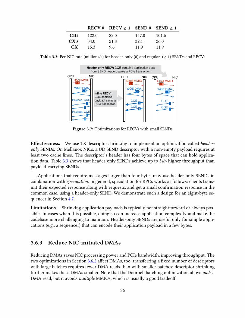
RECV 0 RECV ≥ 1 SEND 0 SEND ≥ 1
CIB 122.0 82.0 157.0 101.6CX3 34.0 21.8 32.1 26.0CX 15.3 9.6 11.9 11.9
Table 3.3: Per-NIC rate (millions/s) for header-only (0) and regular (≥ 1) SENDs and RECVs
1, 2Dbell MMIO
WQE DMA
CPU NIC
Payload, CQE1
1
Payload, CQE2
2
Dbell MMIO
WQE DMA
CPU NIC
CQE1
CQE2
Header-only RECV: CQE contains application datafrom SEND header; saves a PCIe transaction
Inline RECV: CQE containspayload; saves a PCIe transaction
Dbell MMIO
WQE DMA
CPU NIC
CQE1
CQE2
1, 2
1, 2 1, 2
1, 2 1, 2
Figure 3.7: Optimizations for RECVs with small SENDs
E�ectiveness. We use TX descriptor shrinking to implement an optimization called header-only SENDs. On Mellanox NICs, a UD SEND descriptor with a non-empty payload requires atleast two cache lines. The descriptor’s header has four bytes of space that can hold applica-tion data. Table 3.3 shows that header-only SENDs achieve up to 54% higher throughput thanpayload-carrying SENDs.
Applications that require messages larger than four bytes may use header-only SENDs incombination with speculation. In general, speculation for RPCs works as follows: clients trans-mit their expected response along with requests, and get a small con�rmation response in thecommon case, using a header-only SEND. We demonstrate such a design for an eight-byte se-quencer in Section 4.7.
Limitations. Shrinking application payloads is typically not straightforward or always pos-sible. In cases when it is possible, doing so can increase application complexity and make thecodebase more challenging to maintain. Header-only SENDs are useful only for simple appli-cations (e.g., a sequencer) that can encode their application payload in a few bytes.
3.6.3 Reduce NIC-initiated DMAs
Reducing DMAs saves NIC processing power and PCIe bandwidth, improving throughput. Thetwo optimizations in Section 3.6.2 a�ect DMAs, too: transferring a �xed number of descriptorswith large batches requires fewer DMA reads than with smaller batches; descriptor shrinkingfurther makes these DMAs smaller. Note that the Doorbell batching optimization above adds aDMA read, but it avoids multiple MMIOs, which is usually a good tradeo�.
36

3.6.3.1 Payload inlining
Inlining reduces latency, NIC processing, and PCIe bandwidth use by eliminating the DMA readfor the payload. By default, TX queue descriptors (i.e., descriptors for packet transmission innon-RDMA NICs, as well as RDMA writes and SENDs) contain a pointer to the payload; theNIC fetches it via a DMA read. Modern NICs typically support encapsulating small payloadsup to a few hundred bytes inside the descriptor. The CPU can then write the inlined descriptorto the NIC using Descriptor-MMIO, or the NIC can fetch it using DMA.
E�ectiveness. We demonstrate the performance bene�ts of inlining in the context of RDMAin detail in Chapter 4. For example, the round-trip latency of an inlined WRITE is up to 400 nslower than a non-inlined WRITE (Figure 4.1). For HERD’s choice of RDMA primitives to im-plement RPCs, inlining improves RPC throughput by 35% for 32 B requests and responses (Fig-ure 4.4).
Limitations. Inlining increases descriptor size, increasing the size (in bytes) of TX queues.This results in a higher NIC memory footprint per queue, reducing the number of TX queuesthe NIC can hold before su�ering cache misses. On modern multi-CPU platforms, it is possiblefor over one hundred cores to share a NIC, requiring at least one hundred datagram queues fore�cient network I/O without expensive sharing of queues among cores.
We have found that using smaller, non-inlined descriptors increases the number of cores anRPC library can support before su�ering from NIC cache misses. eRPC supports changing thesize of the inlined payload to allow users to make a tradeo� between low latency from enablinginlining, and higher number-of-cores scalability from disabling inlining.
3.6.3.2 Unsignaled transmission
A feature in modern NICs allows omitting TX completion queue entries, improving perfor-mance by reducing PCIe bandwidth use, and NIC and CPU processing. Host software maymark TX queue descriptors as unsignaled by setting a �ag in the descriptor. The host’s NICdoes not DMA-write a CQE for these operations. An application that uses unsignaled trans-mission may detect TX completion using other, application-speci�c methods. For example, anRPC library at the client side may use the server’s response as an implicit signal for the com-pletion of request transmission, instead of relying on an explicit CQE from the client’s NIC.In Chapter 6, we show how an RPC library can use unsignaled request transmission even in alossy network that might drop the response.
Communication patterns that lack implicit ACKs, such as messaging and RPC chains (Sec-tion 3.5.1), can use a variant of unsignaled transmission, called selective signaling. With oneTX queue, selective signaling works as follows: we post N unsignaled descriptors, followed byone signaled descriptor. The NIC processes descriptors in a TX queue in order, so the CQE forthe signaled descriptor indicates transmission completion for the previous N descriptors. Thistechnique cuts down CQE overhead by a factor of N . We typically use values of N between 32and 128, making CQE overhead negligible.
37
E�ectiveness. In Section 4.3.2.2, we show that using unsignaled completions improves RPCperformance by 10–43%, measured with di�erent combinations of RDMA primitives used toimplement RPCs. All three RPC designs presented in this thesis use unsignaled completions.
Limitations. One potential drawback of unsignaled transmission is reduced packet pacingprecision, leading to bursty tra�c that might cause queue buildup in network switches. Withsignaled transmission, the client’s RPC library has more control over the rate at which itsNIC places packets on the wire: CQEs generated by the client’s local NIC are a �ne-grainedand predictable mechanism for clocking packet transmission. Implicit completions generatedby remote software are relatively coarse-grained, and less predictable than CQEs because anapplication-level request handler at the server governs response turnaround time. We do notexplore this drawback of unsignaled completions in this thesis.
3.6.3.3 Header-only RECVs
Unlike TX queue operations, NICs must DMA a completion queue entry for completed RXqueue operations; this provides an additional optimization opportunity, as discussed below. RXCQEs contain important metadata such as the size of received data, whereas TX CQEs onlysignal completion, and are therefore dispensible, NICs typically generate two separate DMAwrites for payload and completion, writing them to application- and driver-owned memoryrespectively.
Assume that the corresponding SEND for a RECV carries an X -byte payload. If X = 0 (i.e.,the SEND is header-only), the payload DMA is not generated at the receiver. Some informationfrom the packet’s header is included in the DMA-ed CQE, which can be used to implementapplication protocols.
E�ectiveness. Header-only RECVs are useful in the applications of header-only SENDs, dis-cussed earlier in Section 3.6.3.1. Table 3.3 shows that header-only RECVs achieve up to 62%higher throughput than payload-carrying RECVs. In all three clusters, header-only RECVsachieve similar throughput as inbound RDMA writes. This observation explains the rule ofthumb that two-sided operations are slower than RDMA writes: RDMA writes generate onlyone DMA write at the responder, whereas RECVs normally generate two.
Limitations. The limitations of header-only RECVs are similar to header-only SENDs (Sec-tion 3.6.2.2).
3.7 Guidelines based on NIC architecture
We next present three guidelines based on three di�erent aspects of the hardware architectureof modern high-speed NICs: parallelism, concurrency control, and caching. Although it iswell-known that these aspects a�ect performance of computing devices, their e�ect on NICperformance has received little attention in the past.
38

0
10
20
30
40
CX CX3 CIB
Rat
e (m
illion
s/se
c)
baseline+batching,16+2 QPs+4 QPs
2.1
12.410.0
2.3
9.9 9.6
4.3
19.6 18.6
5.9
19.7
32.2
Figure 3.8: E�ect of optimizations on single-core UD SEND throughput with a 60 B payload. Eachdescriptor spans two cache lines, so the NIC reads 128 B per descriptor.
3.7.1 Engage multiple NIC processing units
Exploiting NIC parallelism is necessary for high performance, but requires explicit attention. Acommon design decision in networking software is to use one NIC TX queue per CPU core, butdoing so limits NIC parallelism to the number of queues. This is because operations on the sameTX queue have ordering dependencies and are ideally handled by the same NIC processing unitto avoid synchronization across PUs.
For example, in datagram-based communication, one TX queue per CPU core is su�cientfor communication with all remote hosts. Using one TX queue consumes the least NIC SRAMto hold queue state, while avoiding queue sharing among CPU cores. However, it “binds” aCPU core to a PU and may limit core throughput to PU throughput. This is likely to happenwhen per-message application processing is small, and a high-speed CPU core overwhelms aless powerful PU. In such cases, using multiple TX queues per core increases CPU e�ciency;we call this the multi-queue optimization.
E�ectiveness. Figure 3.8 shows single-core throughput for batched and non-batched 60 BUD SENDs—the largest payload size for which the TX descriptors �t in two cache lines. Inter-estingly, batching decreases core throughput if only one TX queue is used: with one queue, acore is coupled to a NIC processing unit, so throughput depends on how the PU handles batchedand non-batched operations. Batching has the expected e�ect when we break this coupling byusing multiple queues. Batched throughput increases by ∼ 2x on all clusters with two queues,and between 2–3.2x with four queues. Non-batched (i.e., Descriptor-MMIO) throughput doesnot increase with multiple queues (not shown in graph), showing that it is CPU-limited.
Designing distributed systems often requires choosing between CPU-bypassing and CPU-involving designs. Our results show that achieving peak message rate on even the most pow-erful NICs does not require a prohibitive amount of CPU power: just four cores saturate evenPCIe 3.0 x16. Therefore, CPU-involving designs will not be limited by CPU processing power,provided that their application-level processing permits so.
39
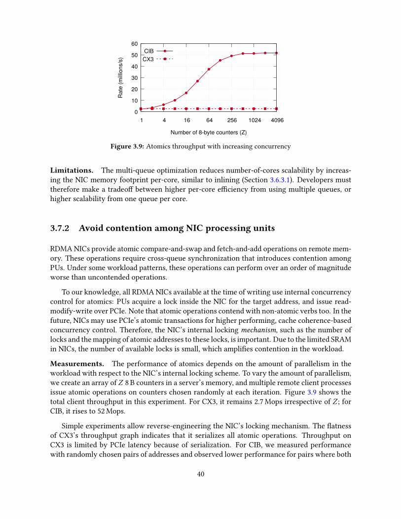
0
10
20
30
40
50
60
1 4 16 64 256 1024 4096R
ate
(milli
ons/
s)
Number of 8-byte counters (Z)
CIBCX3
Figure 3.9: Atomics throughput with increasing concurrency
Limitations. The multi-queue optimization reduces number-of-cores scalability by increas-ing the NIC memory footprint per-core, similar to inlining (Section 3.6.3.1). Developers musttherefore make a tradeo� between higher per-core e�ciency from using multiple queues, orhigher scalability from one queue per core.
3.7.2 Avoid contention among NIC processing units
RDMA NICs provide atomic compare-and-swap and fetch-and-add operations on remote mem-ory. These operations require cross-queue synchronization that introduces contention amongPUs. Under some workload patterns, these operations can perform over an order of magnitudeworse than uncontended operations.
To our knowledge, all RDMA NICs available at the time of writing use internal concurrencycontrol for atomics: PUs acquire a lock inside the NIC for the target address, and issue read-modify-write over PCIe. Note that atomic operations contend with non-atomic verbs too. In thefuture, NICs may use PCIe’s atomic transactions for higher performing, cache coherence-basedconcurrency control. Therefore, the NIC’s internal locking mechanism, such as the number oflocks and the mapping of atomic addresses to these locks, is important. Due to the limited SRAMin NICs, the number of available locks is small, which ampli�es contention in the workload.
Measurements. The performance of atomics depends on the amount of parallelism in theworkload with respect to the NIC’s internal locking scheme. To vary the amount of parallelism,we create an array of Z 8 B counters in a server’s memory, and multiple remote client processesissue atomic operations on counters chosen randomly at each iteration. Figure 3.9 shows thetotal client throughput in this experiment. For CX3, it remains 2.7 Mops irrespective of Z ; forCIB, it rises to 52 Mops.
Simple experiments allow reverse-engineering the NIC’s locking mechanism. The �atnessof CX3’s throughput graph indicates that it serializes all atomic operations. Throughput onCX3 is limited by PCIe latency because of serialization. For CIB, we measured performancewith randomly chosen pairs of addresses and observed lower performance for pairs where both
40
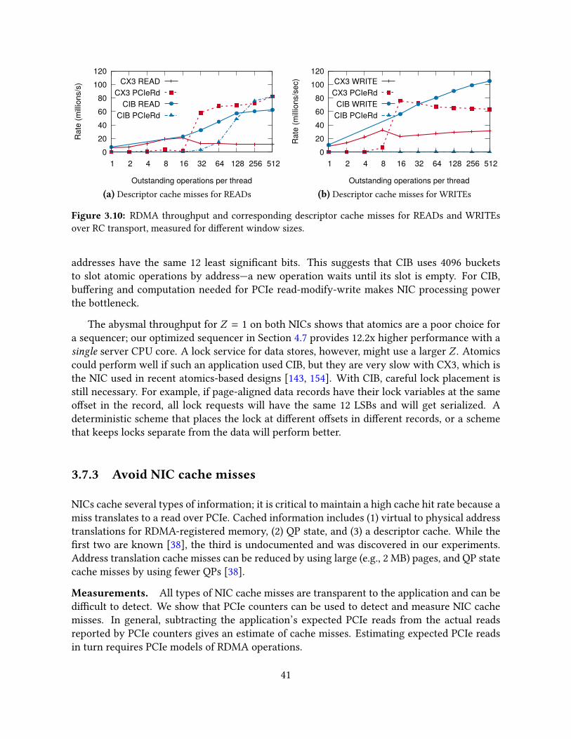
0 20 40 60 80
100 120
1 2 4 8 16 32 64 128 256 512
Rat
e (m
illion
s/s)
Outstanding operations per thread
CX3 READCX3 PCIeRd
CIB READCIB PCIeRd
(a) Descriptor cache misses for READs
0 20 40 60 80
100 120
1 2 4 8 16 32 64 128 256 512
Rat
e (m
illion
s/se
c)
Outstanding operations per thread
CX3 WRITECX3 PCIeRd
CIB WRITECIB PCIeRd
(b) Descriptor cache misses for WRITEs
Figure 3.10: RDMA throughput and corresponding descriptor cache misses for READs and WRITEsover RC transport, measured for di�erent window sizes.
addresses have the same 12 least signi�cant bits. This suggests that CIB uses 4096 bucketsto slot atomic operations by address—a new operation waits until its slot is empty. For CIB,bu�ering and computation needed for PCIe read-modify-write makes NIC processing powerthe bottleneck.
The abysmal throughput for Z = 1 on both NICs shows that atomics are a poor choice fora sequencer; our optimized sequencer in Section 4.7 provides 12.2x higher performance with asingle server CPU core. A lock service for data stores, however, might use a larger Z . Atomicscould perform well if such an application used CIB, but they are very slow with CX3, which isthe NIC used in recent atomics-based designs [143, 154]. With CIB, careful lock placement isstill necessary. For example, if page-aligned data records have their lock variables at the sameo�set in the record, all lock requests will have the same 12 LSBs and will get serialized. Adeterministic scheme that places the lock at di�erent o�sets in di�erent records, or a schemethat keeps locks separate from the data will perform better.
3.7.3 Avoid NIC cache misses
NICs cache several types of information; it is critical to maintain a high cache hit rate because amiss translates to a read over PCIe. Cached information includes (1) virtual to physical addresstranslations for RDMA-registered memory, (2) QP state, and (3) a descriptor cache. While the�rst two are known [38], the third is undocumented and was discovered in our experiments.Address translation cache misses can be reduced by using large (e.g., 2 MB) pages, and QP statecache misses by using fewer QPs [38].
Measurements. All types of NIC cache misses are transparent to the application and can bedi�cult to detect. We show that PCIe counters can be used to detect and measure NIC cachemisses. In general, subtracting the application’s expected PCIe reads from the actual readsreported by PCIe counters gives an estimate of cache misses. Estimating expected PCIe readsin turn requires PCIe models of RDMA operations.
41

Achieving high outbound throughput requires maintaining multiple outstanding transmis-sions via pipelining. On receiving a new descriptor from the CPU, the NIC saves the descriptorin its descriptor cache. However, if the CPU injects new descriptors faster than the NIC’s pro-cessing speed, this descriptor can be evicted by newer descriptors. When the NIC eventuallyprocesses the evicted descriptor, a cache miss occurs.
Figure 3.10 quanti�es this phenomenon on CIB for RDMA reads and writes over RC trans-port. For these operations, the requester’s NIC can su�er a cache miss when generating theRDMA request packet, or while servicing the RDMA response. We conduct the following ex-periment: 14 requester threads on a server issue windows of N 8 B READs or WRITEs over RCtransport to 14 remote processes. In Figures 3.10a and 3.10b, we show the cumulative RDMArequest rate, and the extent of descriptor cache misses using the PCIeRdCur counter rate. Eachthread waits for the N requests to complete before issuing the next window. We use all 14cores on the server to generate the maximum possible request rate, and RC transport to in-clude cache misses generated while processing ACKs for WRITEs. We make the followingobservations, showing the importance of the descriptor cache in improving and understandingcommunication throughput:
• The optimal window size for maximum throughput is not obvious: throughput does notalways increase with increasing window size, and is dependent on the NIC. For example,N = 16 and N = 512 maximize READ throughput on CX3 and CIB respectively.
• Higher throughput may be obtained at the cost of PCIe reads. For example, on CIB, bothREAD throughput and PCIe read rate increases as N increases. Although the largest N isoptimal for a machine that only issues outbound READs, it may be suboptimal if it alsoserves other operations.
• CIB’s NIC can handle the CPU’s peak descriptor injection rate for WRITEs and neversu�ers cache misses. This is not true for READs, suggesting that READs require moreNIC processing than WRITEs.
3.8 Related work
Although there is a large body of work that measures the performance of network communi-cation at a high level [50, 56, 137], there is little prior literature on understanding the low-levelbehavior of network cards. Flajslik and Rosenblum [48] present a high-level picture of basicPCIe interactions between Ethernet NICs and CPUs, but their work does not cover more so-phisticated interactions, such as those that arise during batched transfers. Larsen and Lee [87]study the PCIe behavior of Intel 82599 Ethernet cards using a PCIe protocol analyzer, and dividethe PCIe tra�c into Doorbells, packet descriptors, and actual payloads. We contribute a methodof reasoning about PCIe tra�c that does not depend on an expensive PCIe protocol analyser,and works generally for PCIe-based NICs. In addition, while Larsen and Lee [87] propose toeliminate PCIe with a new integrated DMA controller architecture, we present optimizationsand guidelines of improving PCIe use in the con�nes of existing platform architectures.
42

Several of our guidelines apply to RDMA-based distributed systems that use advanced NICprimitives. A key design decision in such systems is the choice of NIC primitives, made usinga microbenchmark-based performance comparison [38, 113, 154, 155, 159]. Our work showsthat there are more dimensions to such comparisons than these projects explore. The newdimensions include user-controlled aspects such as batching, inlining, and selective signaling,as well as in-NIC aspects that are transparent to the user, such as caching, parallelism, andconcurrency control. A common theme in later chapters of this dissertation is that comparingtwo choices of NIC primitives without exhaustively exploring the space of low-level factors andoptimizations often leads to a sub-optimal choice. We show that our choice of NIC primitives,made based on the guidelines in this chapter, outperforms prior state-of-the-art choices madeusing microbenchmarks that missed some of the low-level factors.
3.9 Conclusion
Designing high-performance distributed systems requires a deep understanding of low-levelhardware details such as PCIe behavior and NIC architecture. We believe that by presentingclear guidelines, signi�cant optimizations based on these guidelines, and tools and experimentsfor low-level measurements on their NIC hardware, our work will help researchers and devel-opers to better use NICs in their high-performance systems.
Over the next three chapters, we will discuss how major design decisions in HERD, FaSST,and eRPC tie back to these guidelines. At these decision points, we will use the Guideline labelto refer back to the insights presented in this chapter.
43

Chapter 4
Case study 1: HERD – An RPC-based key-valuestore
This chapter is the �rst of our two case studies demonstrating the bene�ts of RPC-based designsover those that use in-network capabilities. We present an RPC-based key-value store calledHERD, which is designed to make the best use of an RDMA-capable network. The key insightin HERD is that high-performance RPCs—implemented using RDMA’s low-level primitives—outperform RDMA’s core CPU-bypassing features for key-value access.
Unlike prior RDMA-based key-value systems, we optimize HERD’s design to minimize net-work round trips instead of using one-sided RDMA in an attempt to save CPU cycles at thekey-value server. The result is substantially lower latency, and throughput that saturates mod-ern, commodity RDMA hardware. HERD has two unconventional decisions: First, it does notuse RDMA reads, despite the allure of operations that bypass the remote CPU entirely. Second,it uses a mix of RDMA’s one-sided and two-sided verbs, despite the conventional wisdom thatthe two-sided primitives are slow. A HERD client writes its request into the server’s memory;the server’s CPU computes and sends the reply. This design uses a single round trip for allrequests. Notably, for small key-value items, our full system throughput is similar to nativeRDMA read throughput and is over 2x higher than recent RDMA-based key-value systems.HERD further serves as an e�ective template for the construction of other communication-intensive distributed systems.
4.1 Introduction
This chapter explores a question that has important implications for the design of moderncommunication-intensive distributed systems: What is the best method for using RDMA fea-tures to support remote key-value store access? To answer this question, we �rst evaluatethe performance that, with su�cient attention to engineering, can be achieved by each of theRDMA communication primitives. Using this understanding, we show how to use an unex-pected combination of methods and system architectures to achieve the best throughput and
44

latency possible on a high-performance RDMA network.
Our work is motivated by the seeming contrast between the fundamental time requirementsfor cross-node tra�c vs. CPU-to-memory lookups, and the designs that have recently emergedthat use multiple RDMA reads. As discussed previously in Section 1.2, on the one hand, goingbetween nodes takes roughly 2–10 µs, compared to 60–120 ns for a memory lookup, suggestingthat a multiple-RTT design as found in the recent Pilaf [113] and FaRM [38] systems should befundamentally slower than a single-RTT design. On the other hand, an RDMA read bypassesmany potential sources of overhead, such as servicing interrupts and initiating control transfers,which involve the host CPU. In this chapter, we show that there is a better path to takingadvantage of RDMA to achieve high-throughput, low-latency key-value storage.
A challenge for both our and prior work lies in the lack of richness of RDMA operations.An RDMA operation can only read or write a remote memory location. It is not possible to domore sophisticated operations such as dereferencing and following a pointer in remote mem-ory. Recent work in building key-value stores [38, 113] has focused exclusively on using RDMAreads to traverse remote data structures, similar to what would have been done had the struc-ture been in local memory. This approach invariably requires multiple round trips across thenetwork.
Consider an ideal RDMA read–based key-value store (or cache) where each GET requestrequires only one small RDMA read. Designing such a store is as hard as designing a hash-table in which each GET request requires only one random memory lookup. We instead providea solution to a simpler problem: we design a key-value cache that provides performance similarto that of the ideal cache. However, our design does not use RDMA reads at all.
HERD is a key-value cache that leverages RDMA features to deliver low latency and highthroughput. As we demonstrate later, RDMA reads cannot harness the full performance of theRDMA hardware. In HERD, clients transmit their request to the server’s memory using RDMAwrites. The server’s CPU polls its memory for incoming requests. On receiving a new request, itexecutes the GET or PUT operation in its local data structures and sends the response back to theclient. As RDMA write performance does not scale with the number of outbound connections,a HERD server sends its response with a SEND message over a datagram transport.
We make three main contributions in this chapter:
• We present a thorough analysis of the performance of RDMA verbs, and expose the var-ious design options for key-value systems.
• We provide evidence that RPCs are better than one-sided RDMA reads for key-valuesystems, refuting the previously held assumption [38, 113].
• We describe the design and implementation of HERD, a key-value cache that achieves thebest possible throughput and latency on RDMA hardware.
The following section provides additional background on key-value stores, and describesrecent e�orts in building key-value stores using one-sided RDMA. Section 4.3 discusses therationale behind our design decisions and demonstrates that messaging verbs are a better choice
45
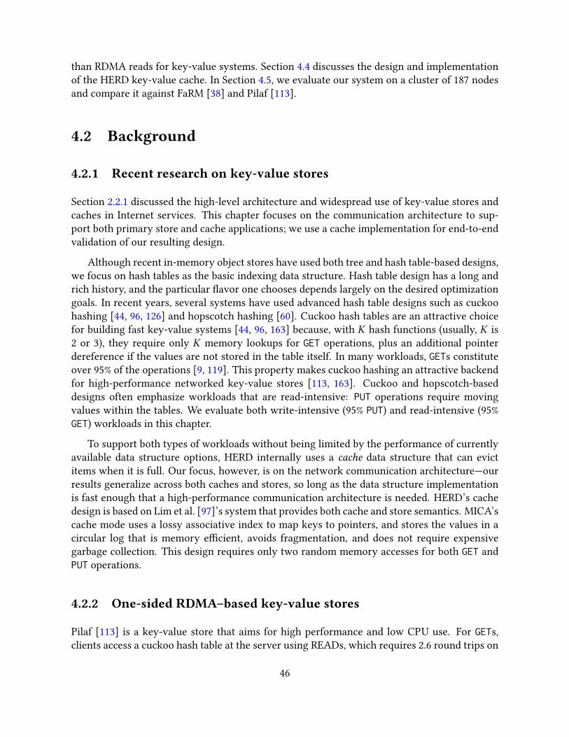
than RDMA reads for key-value systems. Section 4.4 discusses the design and implementationof the HERD key-value cache. In Section 4.5, we evaluate our system on a cluster of 187 nodesand compare it against FaRM [38] and Pilaf [113].
4.2 Background
4.2.1 Recent research on key-value stores
Section 2.2.1 discussed the high-level architecture and widespread use of key-value stores andcaches in Internet services. This chapter focuses on the communication architecture to sup-port both primary store and cache applications; we use a cache implementation for end-to-endvalidation of our resulting design.
Although recent in-memory object stores have used both tree and hash table-based designs,we focus on hash tables as the basic indexing data structure. Hash table design has a long andrich history, and the particular �avor one chooses depends largely on the desired optimizationgoals. In recent years, several systems have used advanced hash table designs such as cuckoohashing [44, 96, 126] and hopscotch hashing [60]. Cuckoo hash tables are an attractive choicefor building fast key-value systems [44, 96, 163] because, with K hash functions (usually, K is2 or 3), they require only K memory lookups for GET operations, plus an additional pointerdereference if the values are not stored in the table itself. In many workloads, GETs constituteover 95% of the operations [9, 119]. This property makes cuckoo hashing an attractive backendfor high-performance networked key-value stores [113, 163]. Cuckoo and hopscotch-baseddesigns often emphasize workloads that are read-intensive: PUT operations require movingvalues within the tables. We evaluate both write-intensive (95% PUT) and read-intensive (95%GET) workloads in this chapter.
To support both types of workloads without being limited by the performance of currentlyavailable data structure options, HERD internally uses a cache data structure that can evictitems when it is full. Our focus, however, is on the network communication architecture—ourresults generalize across both caches and stores, so long as the data structure implementationis fast enough that a high-performance communication architecture is needed. HERD’s cachedesign is based on Lim et al. [97]’s system that provides both cache and store semantics. MICA’scache mode uses a lossy associative index to map keys to pointers, and stores the values in acircular log that is memory e�cient, avoids fragmentation, and does not require expensivegarbage collection. This design requires only two random memory accesses for both GET andPUT operations.
4.2.2 One-sided RDMA–based key-value stores
Pilaf [113] is a key-value store that aims for high performance and low CPU use. For GETs,clients access a cuckoo hash table at the server using READs, which requires 2.6 round trips on
46
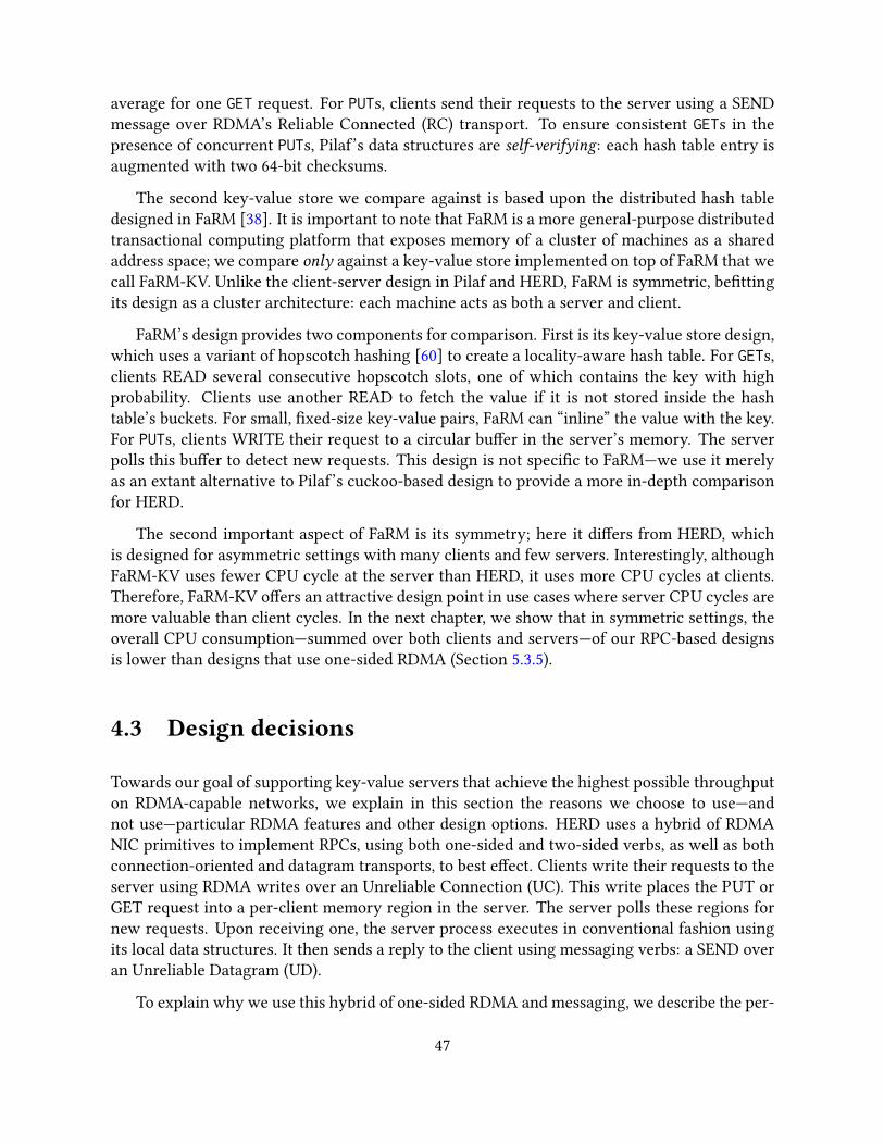
average for one GET request. For PUTs, clients send their requests to the server using a SENDmessage over RDMA’s Reliable Connected (RC) transport. To ensure consistent GETs in thepresence of concurrent PUTs, Pilaf’s data structures are self-verifying: each hash table entry isaugmented with two 64-bit checksums.
The second key-value store we compare against is based upon the distributed hash tabledesigned in FaRM [38]. It is important to note that FaRM is a more general-purpose distributedtransactional computing platform that exposes memory of a cluster of machines as a sharedaddress space; we compare only against a key-value store implemented on top of FaRM that wecall FaRM-KV. Unlike the client-server design in Pilaf and HERD, FaRM is symmetric, be�ttingits design as a cluster architecture: each machine acts as both a server and client.
FaRM’s design provides two components for comparison. First is its key-value store design,which uses a variant of hopscotch hashing [60] to create a locality-aware hash table. For GETs,clients READ several consecutive hopscotch slots, one of which contains the key with highprobability. Clients use another READ to fetch the value if it is not stored inside the hashtable’s buckets. For small, �xed-size key-value pairs, FaRM can “inline” the value with the key.For PUTs, clients WRITE their request to a circular bu�er in the server’s memory. The serverpolls this bu�er to detect new requests. This design is not speci�c to FaRM—we use it merelyas an extant alternative to Pilaf’s cuckoo-based design to provide a more in-depth comparisonfor HERD.
The second important aspect of FaRM is its symmetry; here it di�ers from HERD, whichis designed for asymmetric settings with many clients and few servers. Interestingly, althoughFaRM-KV uses fewer CPU cycle at the server than HERD, it uses more CPU cycles at clients.Therefore, FaRM-KV o�ers an attractive design point in use cases where server CPU cycles aremore valuable than client cycles. In the next chapter, we show that in symmetric settings, theoverall CPU consumption—summed over both clients and servers—of our RPC-based designsis lower than designs that use one-sided RDMA (Section 5.3.5).
4.3 Design decisions
Towards our goal of supporting key-value servers that achieve the highest possible throughputon RDMA-capable networks, we explain in this section the reasons we choose to use—andnot use—particular RDMA features and other design options. HERD uses a hybrid of RDMANIC primitives to implement RPCs, using both one-sided and two-sided verbs, as well as bothconnection-oriented and datagram transports, to best e�ect. Clients write their requests to theserver using RDMA writes over an Unreliable Connection (UC). This write places the PUT orGET request into a per-client memory region in the server. The server polls these regions fornew requests. Upon receiving one, the server process executes in conventional fashion usingits local data structures. It then sends a reply to the client using messaging verbs: a SEND overan Unreliable Datagram (UD).
To explain why we use this hybrid of one-sided RDMA and messaging, we describe the per-
47

formance experiments and analysis that support it. Particularly, we describe our constructionof an RPC primitive that performs as well as single RDMA reads, allowing HERD to outperformprior key-value stores that use multiple RDMA reads for GETs by around 2x. We also describehow HERD’s RPC primitive uses two-sided verbs despite conventional wisdom that they areslower than one-sided RDMA.
4.3.1 Notation and experimental setup
In this section, we present microbenchmarks from the CX3 cluster (Table 2.2), a large testbedequipped with 56 Gbps In�niBand. These experiments use one server machine and several clientmachines. We denote the server machine by MS and its NIC by NICS . We denote client machinei by Ci . The server and client machines may run multiple server and client processes, respec-tively. For throughput experiments, clients maintain a window of several outstanding verbsin their send queues. Using windows allows us to saturate our NICs with fewer processes. Inall of our throughput experiments, we manually tune the window size for maximum aggregatethroughput.
4.3.2 Constructing a fast RPC primitive
We begin by constructing an RPC primitive using two RDMA writes—one for the request andone for the response—that performs similarly to one RDMA read. In the next section, we de-scribe how we improve the scalability of this basic primitive by using UD SENDs for responses,while preserving performance.
The RPC primitive in this section uses WRITEs over the UC transport, which makes it pos-sible to replace one READ by two WRITEs without degrading latency or throughput. Thisis because UC WRITEs have lower latency and higher throughput than READs. First, as onemight expect, the latency of an unsignaled WRITE is about half that (12 RTT) of a READ. Sec-ond, because the UC WRITE’s responder does not need to send ACKs back, its NIC performsless processing, and thus can support higher throughput than with READs. The reduced net-work bandwidth use similarly bene�ts both the server and client throughput. We discuss theseadvantages in detail next.
4.3.2.1 WRITEs have lower latency than READs
Measuring the latency of an unsignaled WRITE is not straightforward because the requestergets no indication of completion. Therefore, we measure it indirectly by measuring the latencyof an “ECHO” RPC. In an ECHO, a client sends a request to a server and the server relays thesame message back to the client. The latency of an unsignaled WRITE is at most half of thelatency of an ECHO implemented with unsignaled WRITEs.
48

Core 1
Core 16
MS
Core 1
Core 16
C1
{RD,WR,WR-I}, RC
WR-I, RC (ECHO)
1
(a) Setup for measuring verbs and ECHO la-tency. We use one client process to issue op-erations to one server process
0
1
2
3
4
4 8 16 32 64 128 256 512 1024
Late
ncy
(mic
rose
cond
s)
Size of payload (bytes)
WR-INLINEWRITE
READECHO
ECHO / 2
(b) The one-way latency of WRITE is half that of ECHO.ECHO operations used unsignaled verbs.
Figure 4.1: Latency of verbs, and ECHO RPCs implemented using UC WRITEs
We also measure the latency of signaled READ and WRITE operations. As these operationsare signaled, we use the completion entry to measure latency. For WRITE, we also report thelatency with payload inlining (Guideline 3.6.3.1). Figure 4.1 shows the average latency fromthese measurements. We use inlined and unsignaled WRITEs for ECHOs. On our ConnectX-3NICs, the maximum size of the inlined payload is 256 B. Therefore, we show graphs for WR-INLINE and ECHO only up to 256 B.
Unsignaled verbs. For payloads up to 64 B, the latency of ECHOs is close to READ latency,which con�rms that the one-way WRITE latency is about half of the READ latency. For largerECHOs, the latency increases because of the time spent in writing WRITE descriptors to theNIC via MMIO.
Signaled verbs. The solid lines in Figure 4.1 show the latencies for three signaled verbs—WRITEs, READs, and WRITEs with inlining (WR-INLINE). READ and WRITE latencies aresimilar because they travel identical network/PCIe paths. By avoiding one DMA operation,inlining reduces the latency of small WRITEs by around 400 ns.
4.3.2.2 WRITEs have higher throughput than READs
To evaluate throughput, it is �rst necessary to observe that with many client machines com-municating with one server, di�erent verbs perform very di�erently when used at the clients(talking to one server) and at the server (talking to many clients).
Inbound throughput. We �rst measure the throughput of inbound verbs, i.e., the rate ofverbs that multiple remote machines (the clients) can issue to one machine (the server). Usingthe notation introduced above, C1, ...,CN issue operations to MS , as shown in Figure 4.2a. Fig-ure 4.2b shows the cumulative throughput observed across the active machines. For up to 128 Bpayloads, WRITEs achieve 35 Mops, which is 34% higher than the maximum READ throughput(26 Mops). Interestingly, reliable WRITEs deliver signi�cantly higher throughput than READs
49
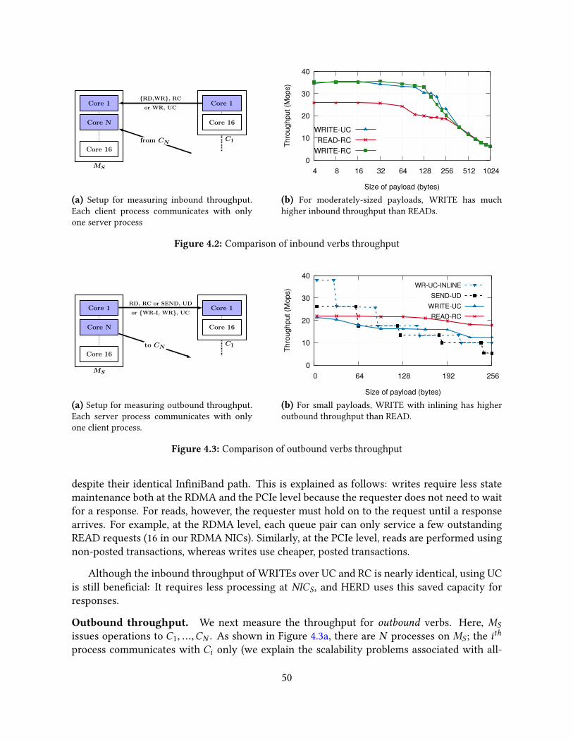
Core 1
Core N
Core 16
MS
Core 1
Core 16
C1
{RD,WR}, RC
or WR, UC
from CN
1
(a) Setup for measuring inbound throughput.Each client process communicates with onlyone server process
0
10
20
30
40
4 8 16 32 64 128 256 512 1024
Thro
ughp
ut (M
ops)
Size of payload (bytes)
WRITE-UCREAD-RC
WRITE-RC
(b) For moderately-sized payloads, WRITE has muchhigher inbound throughput than READs.
Figure 4.2: Comparison of inbound verbs throughput
Core 1
Core N
Core 16
MS
Core 1
Core 16
C1
RD, RC or SEND, UD
or {WR-I, WR}, UC
to CN
1
(a) Setup for measuring outbound throughput.Each server process communicates with onlyone client process.
0
10
20
30
40
0 64 128 192 256
Thro
ughp
ut (M
ops)
Size of payload (bytes)
WR-UC-INLINESEND-UD
WRITE-UCREAD-RC
(b) For small payloads, WRITE with inlining has higheroutbound throughput than READ.
Figure 4.3: Comparison of outbound verbs throughput
despite their identical In�niBand path. This is explained as follows: writes require less statemaintenance both at the RDMA and the PCIe level because the requester does not need to waitfor a response. For reads, however, the requester must hold on to the request until a responsearrives. For example, at the RDMA level, each queue pair can only service a few outstandingREAD requests (16 in our RDMA NICs). Similarly, at the PCIe level, reads are performed usingnon-posted transactions, whereas writes use cheaper, posted transactions.
Although the inbound throughput of WRITEs over UC and RC is nearly identical, using UCis still bene�cial: It requires less processing at NICS , and HERD uses this saved capacity forresponses.
Outbound throughput. We next measure the throughput for outbound verbs. Here, MS
issues operations to C1, ...,CN . As shown in Figure 4.3a, there are N processes on MS ; the ith
process communicates with Ci only (we explain the scalability problems associated with all-
50

0 5
10 15 20 25 30
SEND/SEND WR/WR WR/SEND
Thro
ughp
ut (M
EC
HO
s/s)
basic+unreliable
+unsignalled+inlined
13.515.6 15.5
13.6
16.9 17.519.5 18.5 19.3
21.1
26.0 26.1
Figure 4.4: Throughput of ECHOs with 32 B messages. WR-SEND uses UD transport for responses.
to-all communication later in Section 4.3.3). Apart from READs, WRITEs, and inlined WRITEsover UC, we also measure the throughput for inlined SENDs over UD, for reasons described inSection 4.3.3. Figure 4.3b plots the throughput achieved by MS for di�erent payload sizes. Forsmall sizes, inlined WRITEs and SENDs have signi�cantly higher outbound throughput thanREADs. For large sizes, the throughput of all WRITE and SEND variants is less than READs,but it is never less than 50% of the READ throughput. Thus, even for these larger items, using asingle WRITE (or SEND) for responses remains a better choice than using multiple READs forkey-value items.
ECHO throughput is interesting for two reasons. First, it provides an upper bound on thethroughput of a key-value cache based on one round trip of communication. Second, ECHOshelp characterize the processing power of the RDMA NIC: although the advertised messagerate of the ConnectX-3 cards used in our evaluation of HERD is 35 Mops, bidirectionally, theycan process many more messages.
Varying the verbs and transport types used for the request and the response message yieldsseveral di�erent implementations of RPCs. Figure 4.4 shows the throughput for some of the pos-sible combinations and for ECHO RPCs with 32 B payloads. The �gure also shows that usingunreliable transports, payload inlining, and unsignaled transmission increases ECHO through-put signi�cantly.
ECHOs achieve maximum throughput (26 Mops) when both the request and the responseare sent using RDMA writes. However, as we show in Section 4.3.3, this approach does not scalewith the number of connections. HERD uses RDMA writes over UC for requests and SENDs(over UD) for responses. An ECHO server using this hybrid also achieves 26Mops—it gives theperformance of WRITE-based ECHOs, but with much better scalability.
By avoiding the overhead of posting RECVs at the server, our method of WRITE-based re-quests and SEND-based responses provides better throughput than purely SEND-based ECHORPCs. Interestingly, however, after enabling all optimizations, the throughput of purely SEND-based ECHOs (with no RDMA operations) is 21 Mops, which is more than three-fourths of thepeak inbound READ throughput (26 Mops). Both Pilaf and FaRM have noted that RDMA readsvastly outperform SEND-based ECHOs, which our results agree with if our optimizations are
51
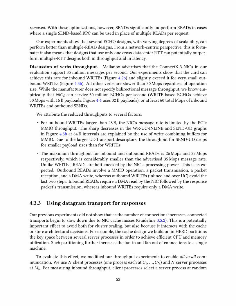
removed. With these optimizations, however, SENDs signi�cantly outperform READs in caseswhere a single SEND-based RPC can be used in place of multiple READs per request.
Our experiments show that several ECHO designs, with varying degrees of scalability, canperform better than multiple-READ designs. From a network-centric perspective, this is fortu-nate: it also means that designs that use only one cross-datacenter RTT can potentially outper-form multiple-RTT designs both in throughput and in latency.
Discussion of verbs throughput. Mellanox advertises that the ConnectX-3 NICs in ourevaluation support 35 million messages per second. Our experiments show that the card canachieve this rate for inbound WRITEs (Figure 4.2b) and slightly exceed it for very small out-bound WRITEs (Figure 4.3b). All other verbs are slower than 30 Mops regardless of operationsize. While the manufacturer does not specify bidirectional message throughput, we know em-pirically that NICS can service 30 million ECHOs per second (WRITE-based ECHOs achieve30 Mops with 16 B payloads; Figure 4.4 uses 32 B payloads), or at least 60 total Mops of inboundWRITEs and outbound SENDs.
We attribute the reduced throughputs to several factors:
• For outbound WRITEs larger than 28 B, the NIC’s message rate is limited by the PCIeMMIO throughput. The sharp decreases in the WR-UC-INLINE and SEND-UD graphsin Figure 4.3b at 64 B intervals are explained by the use of write-combining bu�ers forMMIO. Due to the larger UD transport descriptors, the throughput for SEND-UD dropsfor smaller payload sizes than for WRITEs
• The maximum throughput for inbound and outbound READs is 26 Mops and 22 Mopsrespectively, which is considerably smaller than the advertised 35 Mops message rate.Unlike WRITEs, READs are bottlenecked by the NIC’s processing power. This is as ex-pected. Outbound READs involve a MMIO operation, a packet transmission, a packetreception, and a DMA write, whereas outbound WRITEs (inlined and over UC) avoid thelast two steps. Inbound READs require a DMA read by the NIC followed by the responsepacket’s transmission, whereas inbound WRITEs require only a DMA write.
4.3.3 Using datagram transport for responses
Our previous experiments did not show that as the number of connections increases, connectedtransports begin to slow down due to NIC cache misses (Guideline 3.5.2). This is a potentiallyimportant e�ect to avoid both for cluster scaling, but also because it interacts with the cacheor store architectural decisions. For example, the cache design we build on in HERD partitionsthe key space between several server processes in order to achieve e�cient CPU and memoryutilization. Such partitioning further increases the fan-in and fan out of connections to a singlemachine.
To evaluate this e�ect, we modi�ed our throughput experiments to enable all-to-all com-munication. We use N client processes (one process each at C1, ...,CN ) and N server processesat MS . For measuring inbound throughput, client processes select a server process at random
52

and issue a WRITE to it. For outbound throughput, a server process selects a client at randomand issues a WRITE to it. Figure 4.5 shows the results of these experiments for 32 B messages.Several results stand out:
Outbound WRITEs scale poorly. for N = 16, there are 256 active queue pairs at NICS andthe server-to-clients throughput degrades to 21% of the maximum outbound WRITE throughput(Figure 4.3b). With many active queue pairs, each posted verb can cause a cache miss, severelydegrading performance.
InboundWRITEs scale well. Clients-to-server throughput is high even for N = 16. This isbecause RDMA NICs maintain more connections state at requesters than at responders. There-fore, the server’s NIC can support a much larger number of active queue pairs (QPs) withoutincurring cache misses. The large number of clients amortizes the requester overhead in thisexperiment.
In a di�erent experiment, we used 1600 client processes spread over 16 machines to issueWRITEs over UC to one server process. HERD uses this many-to-one con�guration to reducethe number of active connections at the server (Section 4.4.3). This con�guration also achieves30 Mops.
Outbound WRITEs scale poorly only because NICS must manage many connected queuepairs. This problem cannot be solved if we use connected transports because they require atleast as many queue pairs at MS as the number of client machines. Scaling outbound commu-nication therefore mandates using datagrams. UD transport supports one-to-many communi-cation, i.e., a single UD queue can be used to issue operations to multiple remote UD queues.The main challenge with using UD in a high performance application is that it only supportstwo-sided verbs and not one-sided verbs.
Fortunately, the main overhead of two-sided verbs—posting RECVs and handling RECVcompletions—exists at only the receiver. Senders can directly transmit their requests, similar toissuing RDMA writes. Figure 4.5 shows that, when performed over UD, SEND-side throughputis high and scales well with the number of connected clients.
The slight degradation of SEND throughput beyond 10 connected clients happens becausethe SENDs are unsignaled, i.e., server processes get no indication of verb completion. This leadsto the server processes overwhelming NICS with too many outstanding operations, causingcache misses inside the NIC. As HERD uses SENDs for responding to requests, it can use newrequests as an indication of the completion of old SENDs, thereby avoiding this problem.
4.4 Design of HERD
Our HERD setup consists of one server machine and several client machines. The server ma-chine runs NS server processes. We run NC client processes, uniformly spread across the clientmachines.
53

0
10
20
30
40
0 4 8 12 16Th
roug
hput
(Mop
s)
Number of client processes (= server processes)
In-WRITE-UCOut-WRITE-UCOut-SEND-UD
Figure 4.5: Comparison of UD and UC for all-to-all communication with 32 B payloads. InboundWRITEs over UC and outbound SENDs over UD scale well up to 256 queue pairs. Outbound WRITEsover UC scale poorly. All operations are inlined and unsignaled.
4.4.1 HERD’s key-value data structure
HERD borrows its key-value caching data structures from MICA [97], a high-speed key-valuestore and cache designed for classical Ethernet. We restrict our discussion of MICA to its cachemode. MICA uses a lossy index to map keys to pointers, and stores the actual values in a circularlog. Insertion can cause item eviction from the index (thereby making the index lossy), or fromthe log in a FIFO order. We use MICA’s algorithm for both GETs and PUTs: each GET requires upto two random memory lookups, and each PUT requires one.
MICA shards the key space into several partitions based on the key’s hash. In its ExclusiveRead Exclusive Write (EREW) mode, which we use, each server core has exclusive read andwrite access to one partition. MICA uses the Flow Director [65] feature of modern classicalEthernet NICs to direct request packets to the core responsible for the given key. HERD achievesthe same e�ect by allocating per-core request memory at the server, and allowing clients toWRITE their requests directly to the appropriate core.
4.4.2 Masking DRAM latency with prefetching
To service a GET, a HERD server must perform two random memory lookups, prepare the SENDresponse (with the key’s value inlined in the SEND descriptor), and then post the SEND verbusing the post_send() verbs function. The memory lookups and the post_send() functionare the two main sources of latency at the server. Each random memory access takes 60–120 ns,and the post_send() function takes about 150 ns . While the latter is unavoidable, we can maskthe memory access latency by overlapping memory accesses of one request with computationof another request.
MICA and CuckooSwitch [163] mask latency by overlapping memory fetches and prefetches,or request decoding and prefetches. HERD takes a di�erent approach: we overlap prefetcheswith the post_send() function used to transmit replies. We use the following approach: In
54

0 5
10 15 20 25 30
1 2 3 4 5Th
roug
hput
(Mop
s)
Number of server CPU cores
N = 2, no prefetchN = 2, prefetch
N = 8, no prefetchN = 8, prefetch
Figure 4.6: E�ect of memory prefetching on throughput
HERD, the maximum number of memory lookups for each request is two. We create a requestpipeline in software with two stages. When a request is in stage i of the pipeline, it performsthe i-th memory access for the request and issues a prefetch for the next memory address. Inthis way, requests only access memory for which a prefetch has already been issued. On de-tecting a new request, the server issues a prefetch for the request’s index bucket, advances theold requests in the pipeline, pushes in the new request, and �nally calls post_send() to SENDa reply for the pipeline’s completed request. The server process expects the issued prefetchesto �nish by the time post_send() returns.
Figure 4.6 shows the e�ectiveness of prefetching. We use a WRITE/SEND-based ECHOserver, but this time the server performs N random memory accesses before sending the re-sponse. Prefetching allows fewer cores to deliver higher throughput: �ve cores are su�cient toachieve the peak throughput with even N = 8. We conclude that there is signi�cant headroomto implement more complex key-value applications, for instance, key-value stores, on top ofHERD’s request-reply communication mechanism.
With a large number of server processes, this pipelining scheme can lead to a deadlock. Aserver does not advance its pipeline until it receives a new request, and a client does not advanceits request window until it gets a response. A HERD server process avoids this deadlock bypushing a no-op into the pipeline if it fails to get a new requests for 100 consecutive iterations.
4.4.3 Request format and handling
Clients WRITE their GET and PUT requests to a contiguous memory region on the server ma-chine, which is allocated during initialization. This memory region, called the request region,is shared among all the server processes by mapping it using shmget(). The request regionlogically consists of 1 kB slots, which is the maximum size of a key-value item in HERD.
HERD’s request format is as follows. A GET request consists of only a 16 B keyhash. APUT request contains a 16 B keyhash, a 2 B length �eld specifying the value’s length, and up to1000 B for the value. To poll for incoming requests, we use the left-to-right ordering of PCIe
55

Core 1 Core 2 Core NS
Client 1 Client NC
1 2 W
VALUE LEN KEY
1
Figure 4.7: Layout of the request region at the server
DMA writes [38, 100]. We use the keyhash �eld to poll for new requests; therefore, the keyhashis written to the rightmost bytes of the slot. A non-zero keyhash indicates a new request, andwe do not allow clients to use a zero hash. The server zeroes out the keyhash �eld of the slotafter sending a response, freeing it up for a new request.
Figure 4.7 shows the layout of the request region at the server machine. It consists of sepa-rate chunks for each server process, which are further sub-divided into per-client chunks. Eachper-client chunk consists ofW slots, i.e., each client can have up toW pending requests to eachserver process. The size of the request region is NS · NC ·W KB. With NC = 200, NS = 16 andW = 2, this is approximately 6 MB and �ts inside the server’s L3 cache. Each server processpolls the per-client chunks for new requests in a round robin fashion. If server process s hasseen r requests from client number c , it polls the request region at the request slot numbers · (W · Nc ) + (c ·W ) + r mod W .
A network con�guration using bidirectional, all-to-all, communication with connected trans-ports would requireNC ·NS queue pairs at the server. HERD, however, uses connected transportsfor only the request side of communication, and thus requires only NC connected queue pairs.The initial setup works as follows. An initializer process creates the request region, registersit with NICS , establishes a UC connection with each client, and goes to sleep. The NS serverprocesses then map the request region into their address space via shmget() and do not createadditional connections for receiving requests.
4.4.4 Response format and handling
In HERD, responses are sent as SENDs over UD. Each client creates NS UD QPs, whereas eachserver process uses only one UD QP. Before writing a new request to server process s , a clientposts a RECV to its s-th UD QP. This RECV speci�es the memory area on the client where theserver’s response will be written. Each client allocates a response region containing W · NS
response slots: this region is used for the target addresses in the RECVs. After writing out W
56
requests, the client starts checking for responses by polling for RECV completions. On eachsuccessful completion, it posts another request.
The design outlined thus far deliberately shifts work from the server’s NIC to the client’s,with the assumption that client machines often perform enough other work that saturatingtheir network bandwidth is not their primary concern. The servers, however, in an applicationsuch as Memcached, are often dedicated machines, and achieving high bandwidth is important.
4.5 Evaluation
We evaluate HERD primarily on the In�niBand-based CX3 cluster. To evaluate HERD onRoCE, we use NSF PRObE’s [51] Susitna cluster. Susitna has 36 hosts, equipped with AMD’sOpteron 6272 CPUs, and Mellanox ConnectX-3 NICs connected via PCIe 2.0x8. Although Susitnauses a similar NIC model as CX3, the slower PCIe 2.0 bus reduces the throughput of all com-pared systems. Our evaluation shows that:
• HERD uses the full processing power of the NIC. A single HERD server can process upto 26 million requests per second on ConnectX-3 NICs. For value size up to 60 B, HERD’srequest throughput is higher than even native READ throughput, and is over 2x higherthan that of FaRM-KV and Pilaf.
• HERD delivers its 26 Mops on CX3 with approximately 5 µs average latency. Its latencyis over 2x lower than FaRM-KV and Pilaf at their peak throughput, respectively.
• HERD scales to the moderately-sized CX3 cluster, sustaining peak throughput with over250 connected client processes.
4.5.1 Experimental setup
Unless stated otherwise, we run our throughput and latency experiments on 18 machines inCX3. The 17 client machines run up to three client processes each. With at most four outstand-ing requests per client, our implementation requires at least 36 client processes to saturate theserver’s throughput. We over-provision slightly by using 51 client processes. The server ma-chine runs six server processes, each pinned to a distinct physical core.
Comparison against stripped-down alternatives. In keeping with our focus on under-standing the e�ects of network-related decisions, we compare our (full) HERD implementationagainst simpli�ed implementations of Pilaf and FaRM-KV. These simpli�ed implementationsuse the same communication methods as the originals, but omit the actual key-value storage,instead returning a result instantly. We made this decision for two reasons. First, while workingwith Pilaf’s code, we observed several optimization opportunities; we did not want our eval-uation to depend on the relative performance tuning of the systems. Second, we did not haveaccess to FaRM’s source code. Instead, we created and evaluated emulated versions of the two
57

systems, which do not include their backing data structures. This approach gives these systemsthe maximum performance advantage possible, so the throughput we report for both Pilaf andFaRM-KV may be higher than is actually achievable by those systems.
Pilaf is based on two-level lookups: a hash-table maps keys to pointers. The pointer refers tothe key’s value, stored in �at memory regions called extents. FaRM-KV, in its default operatingmode, uses single-level lookups. It achieves this by inlining values hash-table buckets. It alsohas a two-level mode, where the value is stored “out-of-table.” Because the out-of-table modeis necessary for memory e�ciency with variable length keys, we compare HERD against bothmodes. In the following two subsections, we denote the size of a key, value, and pointer by SK ,SV , and SP respectively.
4.5.1.1 Emulating Pilaf
In K-B cuckoo hashing, K candidate buckets can store a key, determined by K orthogonal hashfunctions. For associativity, each bucket contains B slots. Pilaf uses 3-1 cuckoo hashing with75% memory e�ciency and 1.6 average probes per GET (higher memory e�ciency with fewer,but slightly larger, average probes is possible with 2-4 cuckoo hashing [44]). When reading thehash index with an RDMA read, the smallest unit that must be read is a bucket. A bucket inPilaf has only one slot that contains a 4 B pointer, two 8 B checksums, and a few other �elds.We assume the bucket size in Pilaf to be 32 B for alignment.
GET: A GET in Pilaf consists of 1.6 bucket READs (on average) to �nd the value pointer,followed by a SV -byte READ to fetch the value. It is possible to reduce Pilaf’s latency by issuingconcurrent READs for both cuckoo buckets. As this comes at the cost of decreased throughput,we wait for the �rst READ to complete and issue the second READ only if it is required.
PUT: For a PUT, a client SENDs a SK +SV byte message containing the new key-value item tothe server. This request may require relocating entries in the cuckoo hash-table, but we ignorethat as our evaluation focuses on the network communication only.
In emulating Pilaf, we enable all of our RDMA optimizations for both request types; we callthe resulting system Pilaf-em-OPT.
4.5.1.2 Emulating FaRM-KV
FaRM-KV uses a variant of hopscotch hashing to locate a key in approximately one READ. Itsalgorithm guarantees that a key-value pair is stored in a small neighborhood of the bucket thatthe key hashes to. The size of the neighborhood is tunable, but its authors set it to six to balancegood space utilization and performance for items smaller than 128 B. FaRM-KV can inline thevalues in the buckets, or it can store them separately and only store pointers in the buckets. Wecall our version of FaRM-KV with inlined values FaRM-em and without inlining FaRM-em-VAR(for variable length values).
58
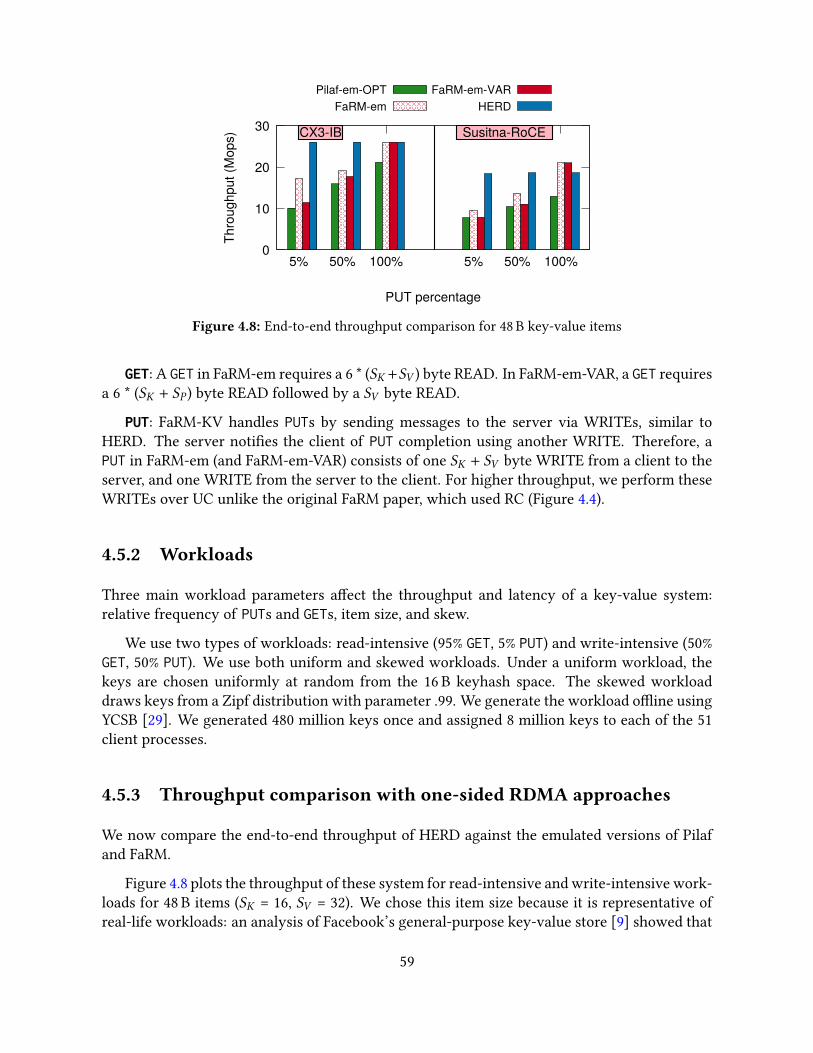
0
10
20
30
5% 50% 100% 5% 50% 100%
Thro
ughp
ut (M
ops)
PUT percentage
Pilaf-em-OPTFaRM-em
FaRM-em-VARHERD
CX3-IB Susitna-RoCE
Figure 4.8: End-to-end throughput comparison for 48 B key-value items
GET: A GET in FaRM-em requires a 6 * (SK +SV ) byte READ. In FaRM-em-VAR, a GET requiresa 6 * (SK + SP ) byte READ followed by a SV byte READ.
PUT: FaRM-KV handles PUTs by sending messages to the server via WRITEs, similar toHERD. The server noti�es the client of PUT completion using another WRITE. Therefore, aPUT in FaRM-em (and FaRM-em-VAR) consists of one SK + SV byte WRITE from a client to theserver, and one WRITE from the server to the client. For higher throughput, we perform theseWRITEs over UC unlike the original FaRM paper, which used RC (Figure 4.4).
4.5.2 Workloads
Three main workload parameters a�ect the throughput and latency of a key-value system:relative frequency of PUTs and GETs, item size, and skew.
We use two types of workloads: read-intensive (95% GET, 5% PUT) and write-intensive (50%GET, 50% PUT). We use both uniform and skewed workloads. Under a uniform workload, thekeys are chosen uniformly at random from the 16 B keyhash space. The skewed workloaddraws keys from a Zipf distribution with parameter .99. We generate the workload o�ine usingYCSB [29]. We generated 480 million keys once and assigned 8 million keys to each of the 51client processes.
4.5.3 Throughput comparison with one-sided RDMA approaches
We now compare the end-to-end throughput of HERD against the emulated versions of Pilafand FaRM.
Figure 4.8 plots the throughput of these system for read-intensive and write-intensive work-loads for 48 B items (SK = 16, SV = 32). We chose this item size because it is representative ofreal-life workloads: an analysis of Facebook’s general-purpose key-value store [9] showed that
59

0
5
10
15
20
25
30
4 8 16 32 64 128 256 512 1024
Thro
ughp
ut (M
ops)
Value size
HERDPilaf-em-OPT
FaRM-em-VARFaRM-em
CX3-IB 0
5
10
15
20
25
4 8 16 32 64 128 256 512 1024
Thro
ughp
ut (M
ops)
Value size
HERDPilaf-em-OPT
FaRM-em-VARFaRM-em
Susitna-RoCE
Figure 4.9: End-to-end throughput comparison with di�erent value sizes
the 50-th percentile of key sizes is approximately 30 B, and that of value sizes is 20 B. To com-pare the READ-based GETs of Pilaf and FaRM with Pilaf’s SEND/RECV-based PUTs, we also plotthe throughput when the workload consists of 100% PUTs.
In HERD, both read-intensive and write-intensive workloads achieve 26 Mops, which isslightly larger than the throughput of native RDMA reads of a similar size (Figure 4.2b). Forsmall key-value items, there is little di�erence between PUT and GET requests at the RDMAlayer because both types of requests �t inside one cache line. Therefore, the throughput doesnot depend on the workload composition.
The throughput of READs directly determines the GET throughput of Pilaf-em-OPT andFaRM-em(-VAR). A GET in Pilaf-em-OPT involves 2.6 READs on average. Its GET throughput is9.9 Mops, which is about 2.6x lower than the maximum READ throughput. For GETs, FaRM-emrequires a single 288 B READ, delivering 17.2 Mops. FaRM-em-VAR requires a second READand has throughput of 11.4 Mops for GETs.
Surprisingly, the PUT throughput in our emulated systems is much larger than their GETthroughput. This is explained as follows. In FaRM-em(-VAR), PUTs use small WRITEs over UCthat outperform the large READs required for GETs. Pilaf-em-OPT uses SEND/RECV-based re-quests and replies for PUT. Both Pilaf and FaRM assume that messaging-based ECHOs are muchmore expensive than READs. (Pilaf reports that for 17 B messages, the throughput of RDMAreads is 2.449 Mops whereas the throughput of SEND/RECV-based ECHOs is only 0.668 Mops.)If SEND/RECV can provide only one fourth the throughput of READ, it makes sense to usemultiple READs for GET.
However, we believe that these systems do not achieve the full capacity of SEND/RECV. Af-ter optimizing SENDs by using unreliable transport, payload inlining, and unsignaled transmis-sion, SEND/RECV based ECHOs, as shown in Figure 4.4, achieve 21 Mops, which is considerablymore than half of our READ throughput (26 Mops). Therefore, we conclude that SEND/RECV-based communication, when used e�ectively, is more e�cient than using multiple READs perrequest.
Figure 4.9 shows the throughput of the three systems with 16 B keys and di�erent value sizes
60

0 2 4 6 8
10 12 14
0 5 10 15 20 25 30La
tenc
y (u
s)
Throughput (Mops)
HERDPilaf-em-OPT
FaRM-emFaRM-em-VAR
CX3-IB
Figure 4.10: End-to-end latency with 48 B items and read-intensive workload
for a read-intensive workload. For up to 60 Mops items, HERD delivers over 26 Mops, which isslightly greater than the peak READ throughput. Up to 32 B values, FaRM-em also delivers highthroughput. However, its throughput declines quickly with increasing value size because thesize of FaRM-em’s READs grow rapidly (as 6 * (SV + 16)). This problem is fundamental to thehopscotch-based data structure that ampli�es the READ size to reduce round trips. FaRM-KVquickly saturates link bandwidths (PCIe or In�niBand/RoCE) with smaller items than HERD,which conserves network bandwidth by transmitting only necessary data. Figure 4.9 illustratesthis e�ect. FaRM-em saturates the PCIe 2.0 bandwidth on Susitna with 4 B values, and the56 Gbps In�niBand bandwidth on CX3 with 32 B values.
HERD hits the PCIe MMIO bottleneck for up to 32 B values on Susitna, and 60 B values onCX3. With large values (144 B on CX3, 192 B on Susitna), HERD switches to using non-inlinedSENDs for responses. The outbound throughput of large inlined messages is less than non-inlined messages because DMA outperforms MMIO for large payloads. For large values, theperformance of HERD, FaRM-em, and Pilaf-em-OPT are within 10% of each other.
4.5.4 Latency comparison with one-sided RDMA approaches
Unlike FaRM-KV and Pilaf, HERD uses only one network round trip for any request. FaRM-KVand Pilaf use one round trip for PUT requests but require multiple round trips for GETs, exceptwhen FaRM-KV inlines values in the hash-table. This causes their GET latency to be higher thanthe latency of a single RDMA READ.
Figure 4.10 compares the average latencies of the three systems for a read-intensive work-load; the error bars indicate the 5th and 95th percentile latency. To understand the dependencyof latency on throughput, we increase the load on the server by adding more clients until theserver is saturated. When using six CPU cores at the server, HERD is able to deliver 26 millionrequests per second with approximately 5 µs average latency. For �xed-length key-value items,FaRM-em provides the lowest latency among the three systems because it requires only onenetwork round trip (unlike Pilaf-em-OPT) and no computation at the server (unlike HERD).
61
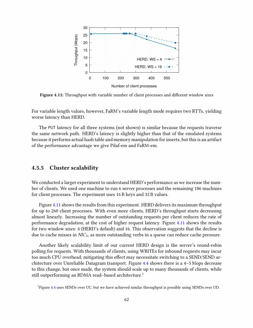
0
5
10
15
20
25
30
0 100 200 300 400 500Th
roug
hput
(Mop
s)
Number of client processes
HERD, WS = 4
HERD, WS = 16
Figure 4.11: Throughput with variable number of client processes and di�erent window sizes
For variable length values, however, FaRM’s variable length mode requires two RTTs, yieldingworse latency than HERD.
The PUT latency for all three systems (not shown) is similar because the requests traversethe same network path. HERD’s latency is slightly higher than that of the emulated systemsbecause it performs actual hash table and memory manipulation for inserts, but this is an artifactof the performance advantage we give Pilaf-em and FaRM-em.
4.5.5 Cluster scalability
We conducted a larger experiment to understand HERD’s performance as we increase the num-ber of clients. We used one machine to run 6 server processes and the remaining 186 machinesfor client processes. The experiment uses 16 B keys and 32 B values.
Figure 4.11 shows the results from this experiment. HERD delivers its maximum throughputfor up to 260 client processes. With even more clients, HERD’s throughput starts decreasingalmost linearly. Increasing the number of outstanding requests per client reduces the rate ofperformance degradation, at the cost of higher request latency. Figure 4.11 shows the resultsfor two window sizes: 4 (HERD’s default) and 16. This observation suggests that the decline isdue to cache misses in NICS , as more outstanding verbs in a queue can reduce cache pressure.
Another likely scalability limit of our current HERD design is the server’s round-robinpolling for requests. With thousands of clients, using WRITEs for inbound requests may incurtoo much CPU overhead; mitigating this e�ect may necessitate switching to a SEND/SEND ar-chitecture over Unreliable Datagram transport. Figure 4.4 shows there is a 4–5 Mops decreaseto this change, but once made, the system should scale up to many thousands of clients, whilestill outperforming an RDMA read–based architecture.1
1Figure 4.4 uses SENDs over UC, but we have achieved similar throughput is possible using SENDs over UD.
62

0
5
10
15
20
25
30
1 2 3 4 5 6 7Th
roug
hput
(Mop
s)
Number of server CPU cores
HERD
Pilaf-em-OPT (PUT)
FaRM-em (PUT)
Figure 4.12: Throughput as a function of the number of server CPU cores
4.5.6 CPU use
A seeming drawback of the HERD’s RPC-based design relative to CPU-bypassing designs is itshigher server CPU use. Below, we put this in context with the total (client + server) CPU usein all systems.
The primary drawback of not using READs in HERD is that GET operations require theserver CPU to execute requests, in exchange for saving one cross-datacenter RTT. While at�rst glance, it might seem that HERD’s CPU usage should be higher than Pilaf and FaRM-KV,we show that in practice these two systems also have signi�cant sources of CPU usage thatreduce the extent of the di�erence.
First, issuing extra READs adds CPU overhead at the Pilaf and FaRM-KV clients. To issue thesecond READ, the clients must poll for the �rst READ to complete. HERD shifts this overheadto the server’s CPU, making more room for application processing at the clients.
Second, handling PUT requests requires CPU involvement at the server. Achieving low-latency PUTs requires dedicating server CPU cores that poll for incoming requests. Therefore,the exact CPU use depends on the fraction of PUT throughput that server is provisioned for,because this determines the CPU resources that must be allocated to it, not the dynamic amountactually used. For example, our experiments show that, even ignoring the cost of updating datastructures, provisioning for 100% PUT throughput in Pilaf and FaRM-KV requires over �ve CPUcores. Figure 4.12 shows FaRM-em and Pilaf-em-OPT’s PUT throughput for 48 B key-value itemsand di�erent numbers of CPU cores at the server. Pilaf-em-OPT’s CPU usage is higher becauseit must post RECVs for new PUT requests, which is more expensive than FaRM-em’s request-region polling.
In Figure 4.12, we also plot HERD’s throughput for the same workload by varying the num-ber of server CPU cores. HERD is able to deliver over 95% of its maximum throughput with 5CPU cores. The modest gap to FaRM-em arises because the HERD server in this experiment ishandling hash table lookups and updates, whereas the emulated FaRM-KV is handling only thenetwork tra�c.
63
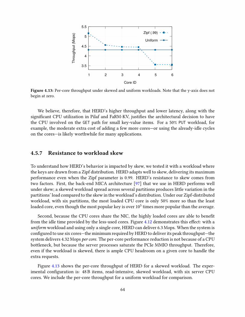
3.5
4
4.5
5
5.5
1 2 3 4 5 6Th
roug
hput
(Mop
s)
Core ID
Zipf (.99)
Uniform
Figure 4.13: Per-core throughput under skewed and uniform workloads. Note that the y-axis does notbegin at zero.
We believe, therefore, that HERD’s higher throughput and lower latency, along with thesigni�cant CPU utilization in Pilaf and FaRM-KV, justi�es the architectural decision to havethe CPU involved on the GET path for small key-value items. For a 50% PUT workload, forexample, the moderate extra cost of adding a few more cores—or using the already-idle cycleson the cores—is likely worthwhile for many applications.
4.5.7 Resistance to workload skew
To understand how HERD’s behavior is impacted by skew, we tested it with a workload wherethe keys are drawn from a Zipf distribution. HERD adapts well to skew, delivering its maximumperformance even when the Zipf parameter is 0.99. HERD’s resistance to skew comes fromtwo factors. First, the back-end MICA architecture [97] that we use in HERD performs wellunder skew; a skewed workload spread across several partitions produces little variation in thepartitions’ load compared to the skew in the workload’s distribution. Under our Zipf-distributedworkload, with six partitions, the most loaded CPU core is only 50% more so than the leastloaded core, even though the most popular key is over 105 times more popular than the average.
Second, because the CPU cores share the NIC, the highly loaded cores are able to bene�tfrom the idle time provided by the less-used cores. Figure 4.12 demonstrates this e�ect: with auniform workload and using only a single core, HERD can deliver 6.3 Mops. When the system iscon�gured to use six cores—the minimum required by HERD to deliver its peak throughput—thesystem delivers 4.32 Mops per core. The per-core performance reduction is not because of a CPUbottleneck, but because the server processes saturate the PCIe MMIO throughput. Therefore,even if the workload is skewed, there is ample CPU headroom on a given core to handle theextra requests.
Figure 4.13 shows the per-core throughput of HERD for a skewed workload. The exper-imental con�guration is: 48 B items, read-intensive, skewed workload, with six server CPUcores. We include the per-core throughput for a uniform workload for comparison.
64

0
20
40
60
80
100
0 2 4 6 8 10 12 14Tp
ut (m
illion
s/se
c)
Number of server CPU cores
Baseline+Batching
READ-based key-value store
Figure 4.14: E�ect of Doorbell batching on HERD’s throughput on CIB with 5% PUTs
4.6 Revisiting HERD’s design for faster NICs
Until now, we have presented the design and evaluation of our original HERD system publishedin SIGCOMM 2014 [79], which uses Mellanox ConnectX-3 NICs. We later received access tothe CIB cluster (Table 2.2) that has newer Mellanox Connect-IB NICs, which can handle up tofour times more messages per second than ConnectX-3 NICs. This provided us an opportunityto revisit HERD’s design in the context of both faster NICs and newer one-sided RDMA–basedkey-value stores.
4.6.1 Applying Doorbell batching to HERD
When we evaluated HERD’s original design on CIB, we found that the server’s CPU couldnot keep up with the NIC’s higher message rate: the bottleneck had shifted from the NIC’sprocessing power in our original evaluation (that used slower ConnectX-3 NICs) to the CPU’sprocessing power. We reduced HERD’s server CPU use by applying Doorbell batching (Guide-line 3.6.2.1), as follows. Instead of handling requests one-by-one, the server processes all avail-able requests in a batch. After processing the requests, instead of sending responses one-by-one using Descriptor-MMIO, the server sends the entire batch of responses using one Doorbell.Note that server-side batching does not signi�cantly increase request latency because we do itopportunistically [80, 97], i.e., our server never waits for a number of requests to accumulate.
We evaluate the e�ect of Doorbell batching on HERD’s performance on CIB using the fol-lowing setup. We run a HERD server with a variable number of threads. We use 128 clientthreads running on eight client machines to issue requests. We pre-populate the key space par-tition owned by each server thread with 8 million key-value pairs, which map 16 B keys to 32 Bvalues. The workload consists of 95% GET and 5% PUT operations, with keys chosen uniformlyat random from the inserted keys.
Figure 4.14 shows HERD’s throughput in the above experiment. We also include the max-imum throughput achievable by a READ-based key-value store such as Pilaf or FaRM-KV that
65
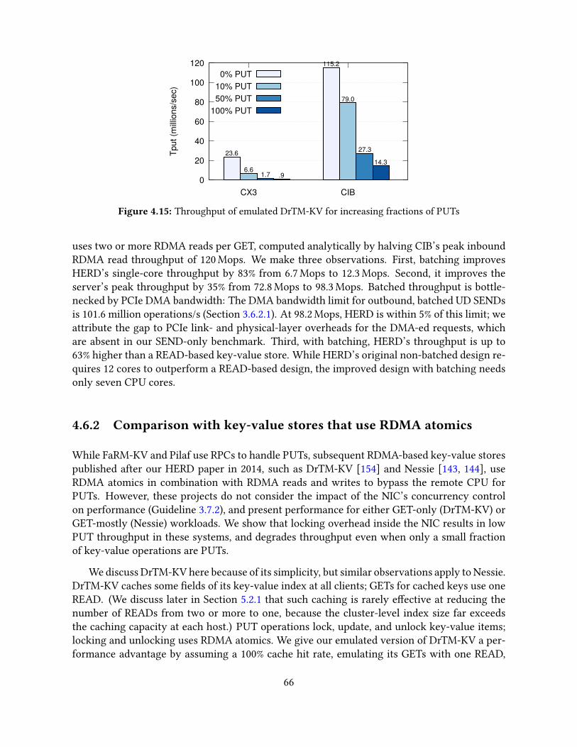
0
20
40
60
80
100
120
CX3 CIB
Tput
(milli
ons/
sec)
0% PUT10% PUT50% PUT
100% PUT
23.6
115.2
6.6
79.0
1.7
27.3
.9
14.3
Figure 4.15: Throughput of emulated DrTM-KV for increasing fractions of PUTs
uses two or more RDMA reads per GET, computed analytically by halving CIB’s peak inboundRDMA read throughput of 120 Mops. We make three observations. First, batching improvesHERD’s single-core throughput by 83% from 6.7 Mops to 12.3 Mops. Second, it improves theserver’s peak throughput by 35% from 72.8 Mops to 98.3 Mops. Batched throughput is bottle-necked by PCIe DMA bandwidth: The DMA bandwidth limit for outbound, batched UD SENDsis 101.6 million operations/s (Section 3.6.2.1). At 98.2 Mops, HERD is within 5% of this limit; weattribute the gap to PCIe link- and physical-layer overheads for the DMA-ed requests, whichare absent in our SEND-only benchmark. Third, with batching, HERD’s throughput is up to63% higher than a READ-based key-value store. While HERD’s original non-batched design re-quires 12 cores to outperform a READ-based design, the improved design with batching needsonly seven CPU cores.
4.6.2 Comparison with key-value stores that use RDMA atomics
While FaRM-KV and Pilaf use RPCs to handle PUTs, subsequent RDMA-based key-value storespublished after our HERD paper in 2014, such as DrTM-KV [154] and Nessie [143, 144], useRDMA atomics in combination with RDMA reads and writes to bypass the remote CPU forPUTs. However, these projects do not consider the impact of the NIC’s concurrency controlon performance (Guideline 3.7.2), and present performance for either GET-only (DrTM-KV) orGET-mostly (Nessie) workloads. We show that locking overhead inside the NIC results in lowPUT throughput in these systems, and degrades throughput even when only a small fractionof key-value operations are PUTs.
We discuss DrTM-KV here because of its simplicity, but similar observations apply to Nessie.DrTM-KV caches some �elds of its key-value index at all clients; GETs for cached keys use oneREAD. (We discuss later in Section 5.2.1 that such caching is rarely e�ective at reducing thenumber of READs from two or more to one, because the cluster-level index size far exceedsthe caching capacity at each host.) PUT operations lock, update, and unlock key-value items;locking and unlocking uses RDMA atomics. We give our emulated version of DrTM-KV a per-formance advantage by assuming a 100% cache hit rate, emulating its GETs with one READ,
66
and its PUTs with two atomics.
Figure 4.15 shows the throughput of our emulated DrTM-KV server on CIB with di�erentfractions of PUT operations in the workload. The server hosts 16 million items with 16 B keysand 32 B values. Clients choose keys uniformly at random and we use as many clients as re-quired to maximize throughput. Although throughput for a 100% GET workload is high, addingonly 10% PUTs degrades it by 72% on CX3 and 31% on CIB. Throughput with 100% PUTs is atiny fraction of GET-only throughput: 4% on CX3 and 12% on CIB. Throughput on CIB de-grades more gradually than CX3 because of the better locking mechanism in Connect-IB NICs(Section 3.7.2).
4.7 A networked sequencer with HERD RPCs
Centralized sequencers are useful building blocks for a variety of network applications, suchas ordering operations in distributed systems via logical or real timestamps [16], or providingincreasing o�sets into a linearly growing memory region [12]. A centralized sequencer canbe the bottleneck in high-performance distributed systems, so building a fast sequencer is animportant step to improving whole-system performance.
We design a sequence server that runs on a single machine and provides an increasing 8 Binteger to client processes running on remote machines. Our baseline design uses HERD RPCs.The server threads share an 8 B counter; each client can send a sequencer request to any thread.The server-side RPC handling consists of atomically incrementing the shared counter by one.When Doorbell batching is enabled, we use an additional application-level optimization to re-duce contention for the shared counter: After collecting B requests, the server thread atomicallyincrements the shared counter by B, thereby claiming ownership of a sequence of B consecutiveintegers. It then sends these B integers to the clients (one integer per client) using a batchedDoorbell.
An important di�erence between our sequencer and the HERD key-value store is the muchsmaller per-request server-side processing in the sequencer. As a result, while per-thread serverthroughput is limited by CPU speed in the key-value store application, it is limited by the NICprocessing unit handling the thread’s UD queue pairs in the sequencer application. We relievethis bottleneck by applying the multi-queue optimization (Guideline 3.7.1, as follows: Eachserver thread alternates among a tunable number of UD QPs across its batched SENDs forresponses.
Figure 4.16 shows the e�ect of batching and multi-queue on the HERD RPC–based se-quencer’s throughput for an increasing number of server CPU cores. We run one server threadper core and use 70 client processes spread across �ve client machines. Batching increasessingle-core throughput from 7.0 Mops to 16.6 Mops. In this mode, each core still uses two re-sponse UD QPs—one for each NIC port on CIB—and is bottlenecked by the two NIC processingunits handling the QPs; engaging more PUs with multi-queue (three per-port QPs per core)increases core throughput to 27.4 Mops. With six cores, and with both Doorbell batching and
67
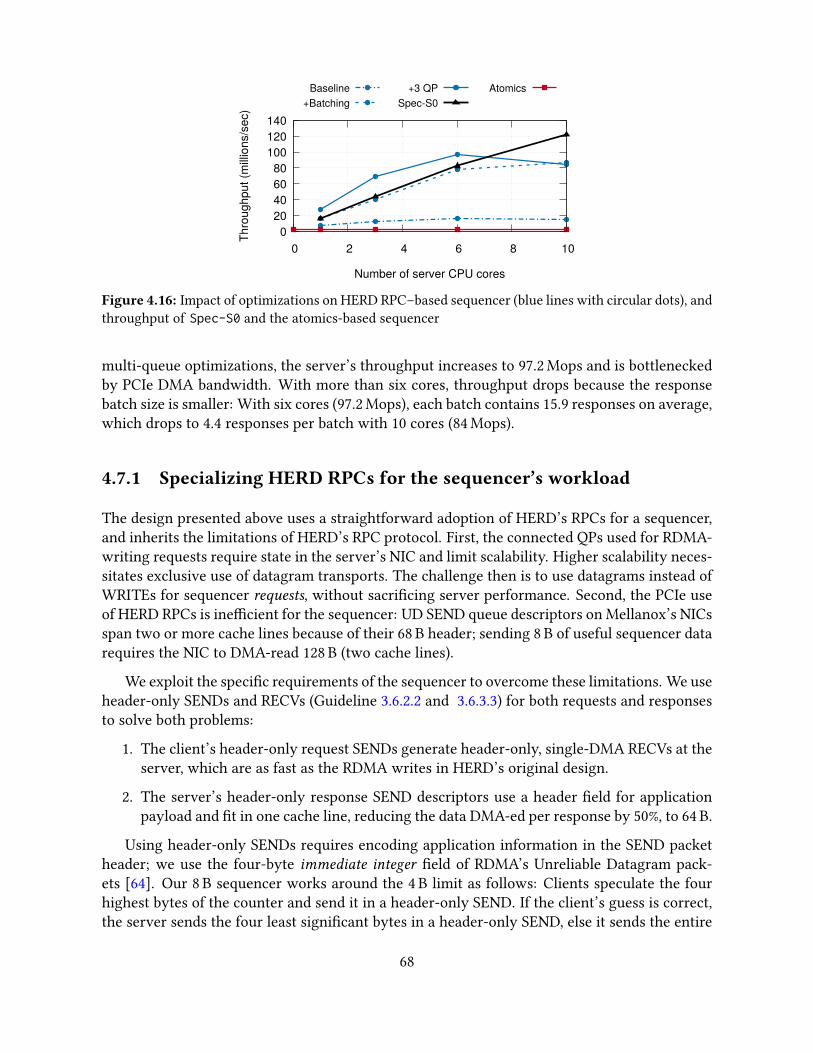
0 20 40 60 80
100 120 140
0 2 4 6 8 10Th
roug
hput
(milli
ons/
sec)
Number of server CPU cores
Baseline+Batching
+3 QPSpec-S0
Atomics
Figure 4.16: Impact of optimizations on HERD RPC–based sequencer (blue lines with circular dots), andthroughput of Spec-S0 and the atomics-based sequencer
multi-queue optimizations, the server’s throughput increases to 97.2 Mops and is bottleneckedby PCIe DMA bandwidth. With more than six cores, throughput drops because the responsebatch size is smaller: With six cores (97.2 Mops), each batch contains 15.9 responses on average,which drops to 4.4 responses per batch with 10 cores (84 Mops).
4.7.1 Specializing HERD RPCs for the sequencer’s workload
The design presented above uses a straightforward adoption of HERD’s RPCs for a sequencer,and inherits the limitations of HERD’s RPC protocol. First, the connected QPs used for RDMA-writing requests require state in the server’s NIC and limit scalability. Higher scalability neces-sitates exclusive use of datagram transports. The challenge then is to use datagrams instead ofWRITEs for sequencer requests, without sacri�cing server performance. Second, the PCIe useof HERD RPCs is ine�cient for the sequencer: UD SEND queue descriptors on Mellanox’s NICsspan two or more cache lines because of their 68 B header; sending 8 B of useful sequencer datarequires the NIC to DMA-read 128 B (two cache lines).
We exploit the speci�c requirements of the sequencer to overcome these limitations. We useheader-only SENDs and RECVs (Guideline 3.6.2.2 and 3.6.3.3) for both requests and responsesto solve both problems:
1. The client’s header-only request SENDs generate header-only, single-DMA RECVs at theserver, which are as fast as the RDMA writes in HERD’s original design.
2. The server’s header-only response SEND descriptors use a header �eld for applicationpayload and �t in one cache line, reducing the data DMA-ed per response by 50%, to 64 B.
Using header-only SENDs requires encoding application information in the SEND packetheader; we use the four-byte immediate integer �eld of RDMA’s Unreliable Datagram pack-ets [64]. Our 8 B sequencer works around the 4 B limit as follows: Clients speculate the fourhighest bytes of the counter and send it in a header-only SEND. If the client’s guess is correct,the server sends the four least signi�cant bytes in a header-only SEND, else it sends the entire
68
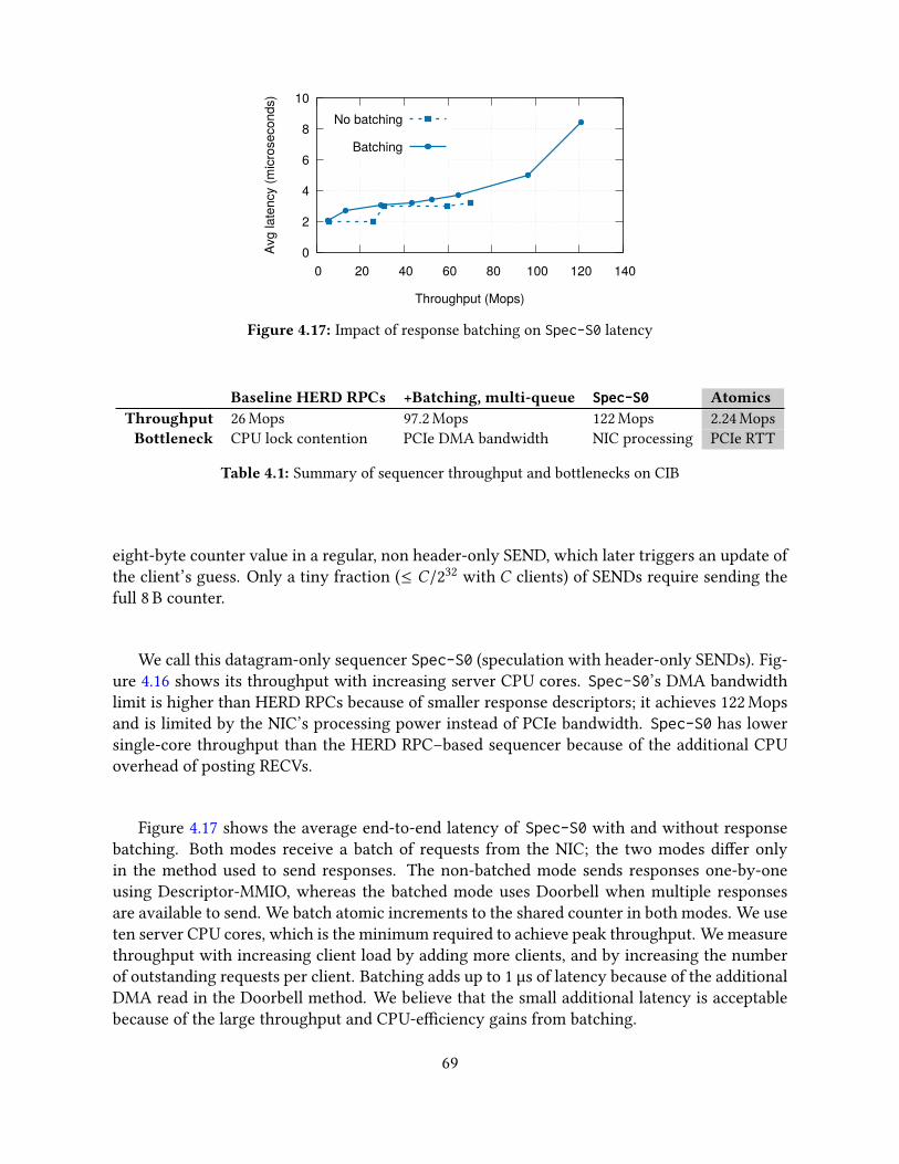
0
2
4
6
8
10
0 20 40 60 80 100 120 140Av
g la
tenc
y (m
icro
seco
nds)
Throughput (Mops)
No batching
Batching
Figure 4.17: Impact of response batching on Spec-S0 latency
Baseline HERD RPCs +Batching, multi-queue Spec-S0 AtomicsThroughput 26 Mops 97.2 Mops 122 Mops 2.24 MopsBottleneck CPU lock contention PCIe DMA bandwidth NIC processing PCIe RTT
Table 4.1: Summary of sequencer throughput and bottlenecks on CIB
eight-byte counter value in a regular, non header-only SEND, which later triggers an update ofthe client’s guess. Only a tiny fraction (≤ C/232 with C clients) of SENDs require sending thefull 8 B counter.
We call this datagram-only sequencer Spec-S0 (speculation with header-only SENDs). Fig-ure 4.16 shows its throughput with increasing server CPU cores. Spec-S0’s DMA bandwidthlimit is higher than HERD RPCs because of smaller response descriptors; it achieves 122 Mopsand is limited by the NIC’s processing power instead of PCIe bandwidth. Spec-S0 has lowersingle-core throughput than the HERD RPC–based sequencer because of the additional CPUoverhead of posting RECVs.
Figure 4.17 shows the average end-to-end latency of Spec-S0 with and without responsebatching. Both modes receive a batch of requests from the NIC; the two modes di�er onlyin the method used to send responses. The non-batched mode sends responses one-by-oneusing Descriptor-MMIO, whereas the batched mode uses Doorbell when multiple responsesare available to send. We batch atomic increments to the shared counter in both modes. We useten server CPU cores, which is the minimum required to achieve peak throughput. We measurethroughput with increasing client load by adding more clients, and by increasing the numberof outstanding requests per client. Batching adds up to 1 µs of latency because of the additionalDMA read in the Doorbell method. We believe that the small additional latency is acceptablebecause of the large throughput and CPU-e�ciency gains from batching.
69

4.7.2 Comparison with atomics-based sequencers
Atomic fetch-and-add over RDMA is an appealing method to implement a sequencer: Binniget al. [16] use this design for the timestamp server in their distributed transaction protocol.However, lock contention for the counter among the NIC’s PUs results in poor performance.The duration for which locks are held—several hundred nanoseconds for PCIe round trips—exacerbates the e�ect of contention. Our RPC-based sequencers have lower contention andshorter lock duration: the programmability of general-purpose CPUs allows us to batch updatesto the counter which reduces cache line contention, and proximity to the counter’s storage (i.e.,core caches) makes these updates fast. Figure 4.16 shows the throughput of our atomics-basedsequencer on CIB: it achieves only 2.24 Mops, which is 50x worse than our optimized design,and 12.2x worse than our single-core throughput.
Table 4.1 summarizes the performance of our sequencers. Interestingly, each design hitsa di�erent hardware bottleneck, highlighting the importance of low-level hardware factors inreasoning about the performance of high-speed networked systems.
4.8 Related work
RDMA in the HPC research community. Jose et al. [77] describe a memcached imple-mentation using a hybrid of UD and RC transports. Their design uses SEND/RECV messagesfor all requests and, for skewed workloads, avoids the overhead of UD transport by activelyswitching connections between RC and UD. Although their cluster (ConnectX NICs, 32 Gbps)is comparable to Susitna (ConnectX-3 NICs, 40 Gbps), their server’s peak request rate is around1.5 Mops, which is over 10x lower than HERD.
The Direct Access File System [33] was one of the �rst to use RDMA in RPCs. It usesSEND/RECV messaging over a connected transport to initiate an RPC, and RDMA reads orwrites to transfer the bulk of large RPC messages. This design is widely used in other systemssuch as RPCs in the Network File System (NFS) [24] and some MPI implementations [101].The MPI implementation for In�niBand by Liu et al. [101] uses RDMA writes for messaging:the server polls the head of a circular bu�er that is written to by a client. HERD extends thismessaging in a scalable fashion for many-to-one request-reply communication.
Several other projects use RDMA verbs to improve the performance of systems such as dis-tributed databases (HBase), Hadoop RPCs, and distributed �le systems (PVFS) [61, 103, 157].Most of these projects use only SEND/RECV verbs as a fast alternative to sockets-based com-munication. The distributed �le system implementation over In�niBand by Wu et al. [157]favors RDMA writes over reads for similar reasons as our work, supporting our observationthat the performance gap between RDMA writes and reads has existed over several gener-ations of RDMA hardware. While several researchers have benchmarked the performance ofRDMA verbs before us [61, 101, 103, 157], they have focused on large messages in the context ofapplications like Network File System and MPI. Our work exploits the performance di�erences
70
that appear only for small messages and are relevant for message rate–bound applications likekey-value stores.
General key-value stores. MICA [97] is a recent key-value system for classical Ethernet.It assigns exclusive partitions to server cores to minimize lock contention, and exploits theNIC’s capability to steer requests to the responsible core. A MICA server with 16 CPU coresand four dual-port, 10 GbE PCIe 2.0 x8 NICs delivers 77 Mops with ≈50 µs average latency(19.25 Mops with one NIC). HERD delivers comparable throughput as MICA, but an order ofmagnitude lower latency. One of HERD’s contributions is showing that MICA’s request-reply–based approach, which was designed for classical Ethernet, works better than CPU-bypassingapproaches on RDMA-capable interconnects. RAMCloud [122] is a DRAM-based, persistentkey-value store that uses RDMA’s messaging verbs for low latency communication. RAMCloudprimarily targets low latency, whereas HERD targets both low latency and high throughput.
4.9 Conclusion
This chapter explored the options for implementing fast, low-latency key-value systems atopRDMA, arriving at an unexpected and novel combination that outperforms prior designs anduses fewer network round-trips. Our work shows that, contrary to widely held beliefs aboutengineering for RDMA, single-RTT designs with server CPU involvement can outperform the“optimization” of CPU-bypassing remote memory access when the RDMA approaches requiremultiple RTTs. Taken together, one lesson from the union of HERD, Pilaf, FaRM, and MICA isthat the biggest boost to throughput comes from bypassing the network stack and avoiding CPUinterrupts, not necessarily from bypassing the CPU entirely. These results contribute not just apractical artifact—the HERD low-latency, high-performance key-value cache—but an improvedunderstanding of how to use datacenter networks to construct high-speed distributed systems.
HERD’s use of NIC-managed connections to send requests works well in its asymmetricsetting with many clients and a few servers. However, in symmetric settings, where every hostacts as both client and server, the large number of active outbound connections at each hostprevents scaling to large clusters. In the next chapter, we show how switching over entirelyto datagram transports allows a more scalable design, as well as CPU savings from Doorbellbatching.
71
“Once you free your mind about a concept of Harmony and ofmusic being correct, you can do whatever you want.”
Giovanni Giorgio Moroder
Chapter 5
Case study 2: FaSST – Fast, Scalable, and SimpleDistributed Transactions
This chapter presents the second of our two case studies: The FaSST distributed transactionprocessing system. In FaSST, we build and improve on the lessons from HERD to create amore �exible and scalable RPC subsystem. Unlike HERD, which uses one-sided RDMA, wechoose to use exclusively datagram transports in FaSST RPCs. This decision brings two bene�ts.First, it makes RPC design more �exible since it does not depend on NIC support for one-sided RDMA. Second, the stateless nature of datagram transports improves scalability, allowingFaSST to handle the large number of communicating pairs in distributed transaction workloads.We show that, counter to prior assumptions, with our optimizations, datagram-based RPCsperform similarly to single one-sided RDMA operations. The insights in this chapter lay downthe groundwork for even higher �exibility and generality in eRPC, presented in the next chapter.
FaSST provides distributed in-memory transactions (Section 2.2.2) with serializability anddurability. Although earlier work in this space sacri�ced strong transactional semantics forperformance [34], recent research shows that the availability of fast networks and non-volatilememory in datacenters now allows high-performance distributed transactions with strong con-sistency [17, 26, 39, 154].1 A common thread in these recent systems is that they rely on one-sided RDMA for performance. The intent behind this decision is to harness one-sided RDMA’sability to save remote CPU cycles.
We show that RPCs implemented over scalable unreliable datagrams are a better primitivethan one-sided RDMA for transactions. Compared to prior systems that use one-sided RDMA,FaSST has all four advantages listed in Chapter 1. First, FaSST is faster because uses fewer roundtrips during the data access phase of transactions. Second, FaSST is more �exible because it doesnot depend on network support for one-sided RDMA. Third, FaSST is more scalable because ituses only connectionless datagram transports. Fourth, FaSST is simpler because of the highergenerality of RPCs compared to RDMA.
1We discuss only distributed transactions in this work, so we use the more general but shorter term transac-tions.
72

Previous high-speed RPC implementations do not perform well in the cluster setting re-quired for transactions. The prior highest-performing RPC design—HERD RPCs—deliver highperformance in an asymmetric setting, with many-to-one communication where one serverhandles RPCs from many clients, but their design does not scale well with all-to-all communi-cation. However, modern high-speed transaction processing systems typically operate in thesymmetric setting, where every host acts as both transaction client and server [39]. This allowsco-locating data with computation when possible, improving performance. HERD’s RPCs donot perform well in the symmetric setting because of NIC cache misses caused by the largenumber of active connected QPs at each transaction processing host.
The key contribution described in this chapter is FaSST RPCs: an all-to-all RPC system thatis fast, scalable, and CPU-e�cient. This is made possible by using only datagrams, which weshow can achieve high performance with our optimizations, such as CPU savings from Doorbellbatching (Guideline 3.6.2). We show that FaSST RPCs provide (1) up to 8x higher throughput,and 13.9x higher CPU e�ciency than FaRM’s RPCs (Section 5.3.5), and (2) 1.7–2.15x higherCPU e�ciency, or higher throughput, than one-sided READs, depending on whether or not theREADs scale to clusters with more than a few tens of nodes (Section 5.2.3).
A novel aspect of FaSST is its handling of lost datagrams. FaSST targets lossless networkswith link-layer �ow control, such as In�niBand, RoCE and OmniPath. In these networks, packetloss is extremely rare because the underlying link layer provides reliability. We did not observeany lost packets in our experiments that transmitted over 50 PB of network data on a real-worldIn�niBand cluster with up to 69 nodes. Nevertheless, packet loss can occur during hardwarefailures, and corner cases of the link-layer’s reliability protocol. We detect these losses withlow CPU overhead using coarse-grained timeouts triggered at the RPC requester, and describehow they can be handled similarly to conventional machine failures.
FaSST uses optimistic concurrency control, two-phase commit, and primary-backup replica-tion for transactions. Our current implementation supports transactions on an unordered key-value store based on MICA [97], and maps 8 B keys to opaque objects. We evaluate FaSST usingthree workloads: a transactional object store, a read-mostly OLTP benchmark called TATP, anda write-intensive OLTP benchmark called SmallBank. FaSST compares favorably against pub-lished per-machine throughput numbers. On TATP, FaSST outperforms FaRM by 1.87x whenusing close to half the hardware (NIC and CPU) resources. On SmallBank, FaSST outperformsDrTM+R [26] by 1.68x with similar hardware without making data locality assumptions.
5.1 Distributed transactions background
This section outlines the environment that we target with FaSST. FaSST aims to provide dis-tributed transactions inside a single datacenter where an instance of the system can scale to afew hundred nodes. Each node in the system is responsible for a partition of the data based ona primary key, and nodes operate in the symmetric model, whereby each node acts both as aclient and a server. For workloads with good data locality (e.g., transactions that only access
73

data in one partition), the symmetric model can achieve higher performance by co-locatingtransactions with the data they access [38, 39].
FaSST targets high-speed, low-latency key-value transaction processing with throughputsof several million transactions/sec and average latencies around one hundred microseconds oncommon OLTP benchmarks with short transactions with up to a few tens of keys. Achievingthis performance requires in-memory transaction processing, and fast userspace network I/Owith polling (i.e., the overhead of a kernel network stack or interrupts is unacceptable). Weassume commercially available network equipment: 10-100 Gbps of per-port bandwidth and≈ 2 µs end-to-end latency.
Making data durable across machine failures requires logging transactions to persistentstorage, and quick recovery requires maintaining multiple replicas of the data store. Keepingpersistent storage such as disk or SSDs on the critical path of transactions limits performance.Similar to recent work, FaSST assumes that the transaction processing nodes are equipped withbattery-backed DRAM [39], though current NVM technologies, such as Intel’s Optane DC Per-sistent Memory, would also work.
Finally, FaSST uses primary-backup replication to achieve fault tolerance. We assume thatfailures will be handled using a separate fault-tolerant con�guration manager that is o� of thecritical path (the Vertical Paxos model [86]), similar to recent work on RDMA-based distributedtransactions [26, 39]. We do not currently implement such a con�guration manager.
5.2 Choosing networking primitives
We now describe the rationale behind our decision to build an RPC layer using two-sided data-gram verbs. We show that FaSST’s RPCs are:
1. Fast. Although READs can outperform similarly-sized FaSST RPCs on small clusters,FaSST RPCs perform better when accounting for the ampli�cation in size or number ofREADs required to access real data stores.
2. Scalable. FaSST RPCs’ throughput and CPU use remains stable as the cluster size in-creases, whereas READ performance degrades because READs must use connected trans-port with today’s NICs.
3. Simple. RPCs reduce the software complexity required to design distributed data storesand transactions compared to one-sided RDMA-based systems.
5.2.1 Advantages of RPCs for transactions
Recent work on designing distributed OLTP systems for modern datacenter networks has largelyfocused on how to use one-sided RDMA primitives. Similar to key-value stores designed forone-sided RDMA, in these designs, clients access remote data structures in servers’ memory
74

using one or more READs, similar to how one would access data in local memory. Various op-timizations help reduce the number of READs needed; we discuss two such optimizations andtheir limitations below.
Value-in-index. As discussed in Section 4.5.1.2, FaRM supports hash table access in ≈ 1READ on average, but at the cost of READ-ing 6–8x more data than strictly necessary. Thisampli�cation highlights the importance of comparing the application-level capabilities of net-working primitives: although micro-benchmarks suggest that READs can outperform similar-sized RPCs, READs require extra network tra�c and/or round-trips due to their CPU-bypassingnature, tipping the scales in the other direction.
Caching the index. DrTM [26, 154] caches the index of its hash table at all servers in thecluster, allowing single-READ GETs; FaRM uses a similar approach for its B-Tree. Althoughthis approach works well when the workload has high locality or skew, it does not work ingeneral because indexes can be large: Zhang et al. [160] report that indexes occupy over 35%of memory for popular OLTP benchmarks in a single-node transaction processing system; thepercentage is similar in our implementation of distributed transaction processing benchmarks.In this case, caching even 10% of the index requires each machine to dedicate 3.5% of the totalcluster memory capacity for the index, which is impossible if the cluster contains more than100/3.5 ≈ 29 nodes. The Cell B-Tree [114] caches B-Tree nodes 4 levels above the leaf nodes tosave memory and reduce churn, but requires multiple round trips (∼ 4) when clients access theB-Tree using READs.
RPCs allow access to partitioned data stores in one round trip. They do not require messagesize ampli�cation, multiple round trips, or caching. The simplicity of RPC-based programmingreduces the software complexity required to take advantage of modern fast networks in trans-action processing: to implement a partitioned, distributed data store, the user writes only shortRPC handlers for a single-node data store. This approach eliminates the software complexityrequired for one-sided RDMA-based approaches. For example, FaSST uses MICA’s hash tabledesign [97] for unordered key-value storage. We made only minor modi�cations to the MICAcodebase to support distributed transactions.
5.2.2 Advantages of datagram transport
Datagram transport allows each CPU core to create one datagram queue that can communicatewith all remote cores. Since the number of queues is relatively small (as many as the numberof cores), providing each core exclusive access to a queue is possible without over�owing theNIC’s cache. Providing exclusive access to RDMA’s RC connections, however, is not scalable:In a cluster with N machines and T threads per machine, doing so requires N ∗T connectionsat every machine, which may not �t in the NIC’s cache. Threads can share connections toreduce their NIC memory footprint [38]. However, sharing connections reduces CPU e�ciencybecause threads contend for locks, and the cache lines for queue descriptors bounce betweenCPU cores. The e�ect can be dramatic: in our experiments, connection sharing reduces theper-core throughput of READs by up to 5.4x (Section 5.2.3.2). Similarly, FaRM’s RPCs that use
75
one-sided WRITEs and connection sharing become CPU-bottlenecked at 5 million requests/sec(Mrps) per machine [39]. Our datagram-based RPCs, however, do not require QP sharing andachieve up to 40.9 Mrps per machine, and even then they are bottlenecked by the NIC, not CPU(Section 5.2.3.1).
In comparison with connected transports, datagram transport confers a second importantadvantage in addition to scalability: Doorbell batching, which reduces CPU use (Guideline 3.6.2).In transactional systems, applications can amortize the cost of posting descriptors to the data-gram queue by ringing the doorbell once for multiple descriptors. Examples include reading orvalidating multiple keys for multi-key transactions, or sending update messages to the repli-cas of a key. With a datagram queue, the process only needs to ring the Doorbell once perbatch, regardless of the individual message destinations within the batch. With connected QPs,however, the process must ring multiple Doorbells—as many as the number of destinationsappearing in the batch. Note that Doorbell batching does not put multiple application-levelmessages in a single network packet. Doorbell batching also does not add latency because wedo it opportunistically, i.e., we do not wait for a batch of messages to accumulate.
5.2.3 Performance considerations
HERD’s RPC performs similarly to READs, but only in the asymmetric setting where multipleclients send requests to one server. In this setting, HERD’s approach scales well with the numberof clients because the number of active queues at the server is small. The server’s connectedQPs are passive because the server’s CPU does not access them; these passive QPs consumelittle memory in the NIC. The active datagram queues are few in number.
In FaRM, Dragojević et al. [39] note that HERD’s RPC design does not scale well in thesymmetric setting required for distributed transactions, where every machine issues requestsand responses. This scenario requires many active QPs on each node for sending requests. InFaRM’s experiments [39] in the symmetric setting, READs outperform their RPCs by 4x.
We now present experimental results showing that FaSST’s datagram-based RPCs are abetter choice than one-sided RDMA for distributed transactions. We discuss the design andimplementation of FaSST’s RPC subsystem in detail in Section 5.3; here, we use it to implementbasic RPCs where both the request and reply are �xed-size bu�ers. We �rst compare the rawthroughput of RPCs and one-sided READs by using a small cluster where READs do not requireconnection sharing. Next, we compare their performance on more realistic, medium-sized clus-ters.
Experiment setup. We conduct our experiments on the CX3 and CIB clusters (Table 2.2).We use machines in a symmetric setting, i.e., every machine issues requests (RPC requests orREADs) to every other machine. For READs without connection sharing, each thread creates asmany RC QPs as the number of machines, and issues READs to randomly chosen machines. Weevaluate RPC performance for two request batch sizes (1 and 11) to show the e�ect of Doorbellbatching for requests. We prevent RPC-level request coalescing (Section 5.3) by sending eachrequest in a batch to a di�erent machine; this restricts our maximum batch size on CIB to 11.
76
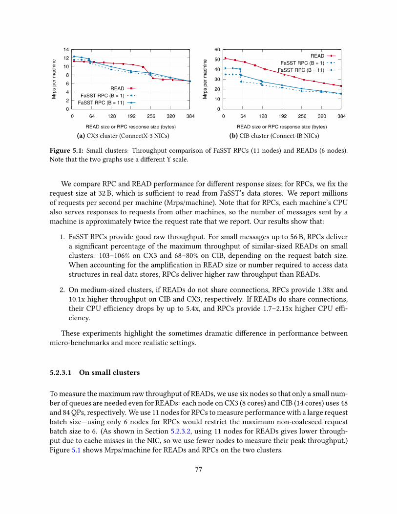
0 2 4 6 8
10 12 14
0 64 128 192 256 320 384
Mrp
s pe
r mac
hine
READ size or RPC response size (bytes)
READFaSST RPC (B = 1)
FaSST RPC (B = 11)
(a) CX3 cluster (ConnectX-3 NICs)
0
10
20
30
40
50
60
0 64 128 192 256 320 384
Mrp
s pe
r mac
hine
READ size or RPC response size (bytes)
READFaSST RPC (B = 1)
FaSST RPC (B = 11)
(b) CIB cluster (Connect-IB NICs)
Figure 5.1: Small clusters: Throughput comparison of FaSST RPCs (11 nodes) and READs (6 nodes).Note that the two graphs use a di�erent Y scale.
We compare RPC and READ performance for di�erent response sizes; for RPCs, we �x therequest size at 32 B, which is su�cient to read from FaSST’s data stores. We report millionsof requests per second per machine (Mrps/machine). Note that for RPCs, each machine’s CPUalso serves responses to requests from other machines, so the number of messages sent by amachine is approximately twice the request rate that we report. Our results show that:
1. FaSST RPCs provide good raw throughput. For small messages up to 56 B, RPCs delivera signi�cant percentage of the maximum throughput of similar-sized READs on smallclusters: 103–106% on CX3 and 68–80% on CIB, depending on the request batch size.When accounting for the ampli�cation in READ size or number required to access datastructures in real data stores, RPCs deliver higher raw throughput than READs.
2. On medium-sized clusters, if READs do not share connections, RPCs provide 1.38x and10.1x higher throughput on CIB and CX3, respectively. If READs do share connections,their CPU e�ciency drops by up to 5.4x, and RPCs provide 1.7–2.15x higher CPU e�-ciency.
These experiments highlight the sometimes dramatic di�erence in performance betweenmicro-benchmarks and more realistic settings.
5.2.3.1 On small clusters
To measure the maximum raw throughput of READs, we use six nodes so that only a small num-ber of queues are needed even for READs: each node on CX3 (8 cores) and CIB (14 cores) uses 48and 84 QPs, respectively. We use 11 nodes for RPCs to measure performance with a large requestbatch size—using only 6 nodes for RPCs would restrict the maximum non-coalesced requestbatch size to 6. (As shown in Section 5.2.3.2, using 11 nodes for READs gives lower through-put due to cache misses in the NIC, so we use fewer nodes to measure their peak throughput.)Figure 5.1 shows Mrps/machine for READs and RPCs on the two clusters.
77
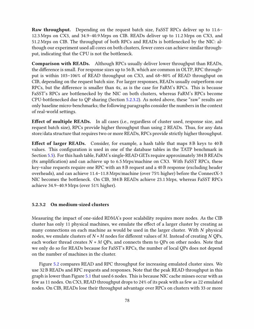
Raw throughput. Depending on the request batch size, FaSST RPCs deliver up to 11.6–12.3 Mrps on CX3, and 34.9–40.9 Mrps on CIB. READs deliver up to 11.2 Mrps on CX3, and51.2 Mrps on CIB. The throughput of both RPCs and READs is bottlenecked by the NIC: al-though our experiment used all cores on both clusters, fewer cores can achieve similar through-put, indicating that the CPU is not the bottleneck.
Comparison with READs. Although RPCs usually deliver lower throughput than READs,the di�erence is small. For response sizes up to 56 B, which are common in OLTP, RPC through-put is within 103–106% of READ throughput on CX3, and 68–80% of READ throughput onCIB, depending on the request batch size. For larger responses, READs usually outperform ourRPCs, but the di�erence is smaller than 4x, as is the case for FaRM’s RPCs. This is becauseFaSST’s RPCs are bottlenecked by the NIC on both clusters, whereas FaRM’s RPCs becomeCPU-bottlenecked due to QP sharing (Section 5.2.3.2). As noted above, these “raw” results areonly baseline micro-benchmarks; the following paragraphs consider the numbers in the contextof real-world settings.
E�ect of multiple READs. In all cases (i.e., regardless of cluster used, response size, andrequest batch size), RPCs provide higher throughput than using 2 READs. Thus, for any datastore/data structure that requires two or more READs, RPCs provide strictly higher throughput.
E�ect of larger READs. Consider, for example, a hash table that maps 8 B keys to 40 Bvalues. This con�guration is used in one of the database tables in the TATP benchmark inSection 5.5). For this hash table, FaRM’s single-READ GETs require approximately 384 B READs(8x ampli�cation) and can achieve up to 6.5 Mrps/machine on CX3. With FaSST RPCs, thesekey-value requests require one RPC with an 8 B request and a 40 B response (excluding headeroverheads), and can achieve 11.4–11.8 Mrps/machine (over 75% higher) before the ConnectX-3NIC becomes the bottleneck. On CIB, 384 B READs achieve 23.1 Mrps, whereas FaSST RPCsachieve 34.9–40.9 Mrps (over 51% higher).
5.2.3.2 On medium-sized clusters
Measuring the impact of one-sided RDMA’s poor scalability requires more nodes. As the CIBcluster has only 11 physical machines, we emulate the e�ect of a larger cluster by creating asmany connections on each machine as would be used in the larger cluster. With N physicalnodes, we emulate clusters of N ∗M nodes for di�erent values of M . Instead of creating N QPs,each worker thread creates N ∗ M QPs, and connects them to QPs on other nodes. Note thatwe only do so for READs because for FaSST’s RPCs, the number of local QPs does not dependon the number of machines in the cluster.
Figure 5.2 compares READ and RPC throughput for increasing emulated cluster sizes. Weuse 32 B READs and RPC requests and responses. Note that the peak READ throughput in thisgraph is lower than Figure 5.1 that used 6 nodes. This is because NIC cache misses occur with asfew as 11 nodes. On CX3, READ throughput drops to 24% of its peak with as few as 22 emulatednodes. On CIB, READs lose their throughput advantage over RPCs on clusters with 33 or more
78
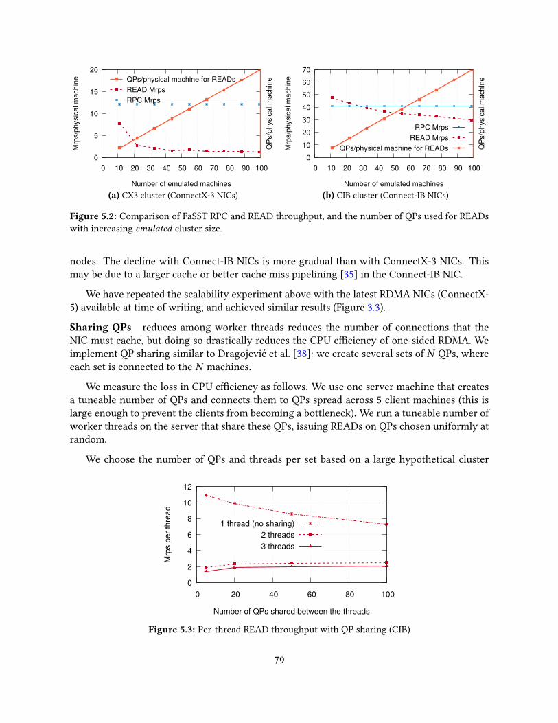
0
5
10
15
20
0 10 20 30 40 50 60 70 80 90 100
Mrp
s/ph
ysic
al m
achi
ne
QPs
/phy
sica
l mac
hine
Number of emulated machines
RPC MrpsREAD MrpsQPs/physical machine for READs
(a) CX3 cluster (ConnectX-3 NICs)
0 10 20 30 40 50 60 70
0 10 20 30 40 50 60 70 80 90 100
Mrp
s/ph
ysic
al m
achi
ne
QPs
/phy
sica
l mac
hine
Number of emulated machines
RPC MrpsREAD Mrps
QPs/physical machine for READs
(b) CIB cluster (Connect-IB NICs)
Figure 5.2: Comparison of FaSST RPC and READ throughput, and the number of QPs used for READswith increasing emulated cluster size.
nodes. The decline with Connect-IB NICs is more gradual than with ConnectX-3 NICs. Thismay be due to a larger cache or better cache miss pipelining [35] in the Connect-IB NIC.
We have repeated the scalability experiment above with the latest RDMA NICs (ConnectX-5) available at time of writing, and achieved similar results (Figure 3.3).
Sharing QPs reduces among worker threads reduces the number of connections that theNIC must cache, but doing so drastically reduces the CPU e�ciency of one-sided RDMA. Weimplement QP sharing similar to Dragojević et al. [38]: we create several sets of N QPs, whereeach set is connected to the N machines.
We measure the loss in CPU e�ciency as follows. We use one server machine that createsa tuneable number of QPs and connects them to QPs spread across 5 client machines (this islarge enough to prevent the clients from becoming a bottleneck). We run a tuneable number ofworker threads on the server that share these QPs, issuing READs on QPs chosen uniformly atrandom.
We choose the number of QPs and threads per set based on a large hypothetical cluster
0
2
4
6
8
10
12
0 20 40 60 80 100
Mrp
s pe
r thr
ead
Number of QPs shared between the threads
1 thread (no sharing)2 threads3 threads
Figure 5.3: Per-thread READ throughput with QP sharing (CIB)
79
with 100 nodes and CIB’s CPUs and NICs. A Connect-IB NIC supports ≈ 400 QPs before READthroughput drops below RPC throughput (Figure 5.2). In this 100-node cluster, the 400 QPs areused to create four sets of 100 connections (QPs) to remote machines. CIB’s CPUs have 14 cores,so sets of 3–4 threads share a QP set.
Figure 5.3 shows per-thread throughput in this experiment. For brevity, we only show re-sults on CIB; the loss in CPU e�ciency is comparable on CX3. The hypothetical con�gurationabove requires sharing 100 QPs among at least three threads; we also show other con�gura-tions that may be relevant for other NICs and cluster sizes. With one thread, there is no sharingof QPs and throughput is high—up to 10.9 Mrps. Throughput with QP sharing between threethreads, however, is 5.4x lower (2 Mrps).
This observation leads to an important question: If the increase in CPU utilization at thelocal CPU due to QP sharing is accounted for, do one-sided READs use fewer cluster-wide CPUcycles than FaSST’s RPCs that do not require QP sharing? We show in Section 5.3 that theanswer is no. FaSST’s RPCs provide 3.4–4.3 Mrps per core on CIB—1.7–2.15x higher than READswith QP sharing between three threads. Note that in our symmetric setting, each core runs bothclient and server code. Therefore, READs use cluster CPU cycles at only the client, whereasRPCs use them at both the client and the server. However, RPCs consume fewer overall CPUcycles.
5.2.4 Reliability considerations
Unreliable transports do not provide reliable packet delivery, which can introduce programmingcomplexity and/or have performance implications (e.g., increased CPU use), since reliabilitymechanisms such as timeouts and retransmissions must be implemented in the software RPClayer or application. In the next chapter on eRPC, we show that these mechanisms are cheapto implement in software.
In FaSST, however, we took a di�erent approach to packet loss, based on two observations.First, we note that transaction processing systems usually include a recon�guration mechanismto handle node failures. Recon�guration includes optionally pausing ongoing transactions, in-forming nodes of the new cluster membership, replaying transaction logs, and re-replicatinglost data [39]. In FaSST, we assume a standard recon�guration mechanism; we have not imple-mented such a mechanism because FaSST’s contribution is not in that space. We expect that,similar to DrTM+R [26], FaRM’s recovery protocol [39] can be adapted to FaSST.
The second observation is that in normal operation, packet loss in modern RDMA networksis extremely rare: in our experiments (discussed below), we observed zero packet loss in over50 PB of data transferred. Packets can be lost during network hardware failures, and cornercases of the link/physical layer reliability protocols. FaSST’s RPC layer detects these lossesusing coarse-grained timeouts maintained by the RPC requester (Section 5.3.3).
Based on these two observations, we believe that an acceptable �rst solution for handlingpacket loss in FaSST is to simply restart one of the two FaSST processes that is a�ected by the
80

lost RPC packet, allowing the recon�guration mechanism to make the commit decision for thea�ected transaction. We discuss this in more detail in Section 5.4.1.
5.2.4.1 Stress tests for packet loss
Restarting a process on packet loss requires packet losses to be extremely rare. To quantifypacket loss on realistic RDMA networks, we set up an experiment on the CX3 cluster, whichis similar to real-world clusters with multiple switches, oversubscription, and sharing. It is ashared cluster with 192 machines arranged in a tree topology with seven leaf and two spineswitches, with an oversubscription ratio of 3.5. The network is shared by Emulab users. Ourlargest experiment used 69 machines connected to �ve leaf switches.
Threads on these machines use In�niBand’s UD transport to exchange 256 B RPCs. Weused 256 B messages to achieve both high network utilization and message rate. Threads send16 requests to remote threads chosen uniformly at random, and wait for all responses to arrivebefore starting the next batch. A thread stops making progress if a request or reply packet islost. Threads routinely output their progress messages to a log �le; we manually inspect these�les to ensure that all threads are making progress.
We ran the experiment without a packet loss for approximately 46 hours. (We stopped theexperiment when a log �le exhausted a node’s disk capacity.) The experiment generated around100 trillion RPC packets and 33.2 B of network data. Including other smaller-scale experimentswith 20–22 nodes, our experiments transferred over 50 PB of network data without a lost packet.
While we observed zero packet loss, we detected several reordered packets. Using sequencenumbers embedded in the RPC packets, we observed around 1500 reordered packets in 100trillion packets transferred. Reordering happens due to multi-path in CX3: although there isusually a single deterministic path between each source and destination node, the In�niBandsubnet manager sometimes recon�gures the switch routing tables to use di�erent paths.
5.3 FaSST RPCs
We designed FaSST’s RPCs speci�cally for transaction workloads that use small (≈ 1000 B orsmaller) objects and a few tens of keys. Key features of FaSST’s RPCs include integration withcoroutines for e�cient network latency hiding, and optimizations such as Doorbell batchingand message coalescing.
5.3.1 Coroutines for network latency hiding
Network latency in modern datacenters is on the order of 10 µs under load, which is muchhigher than the time spent by our applications in computation and local data store accesses. Itis critical to not block a thread while waiting for an RPC reply. Similar to Grappa [117], FaSST
81
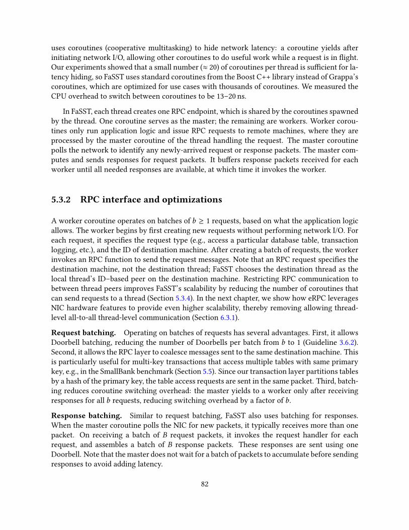
uses coroutines (cooperative multitasking) to hide network latency: a coroutine yields afterinitiating network I/O, allowing other coroutines to do useful work while a request is in �ight.Our experiments showed that a small number (≈ 20) of coroutines per thread is su�cient for la-tency hiding, so FaSST uses standard coroutines from the Boost C++ library instead of Grappa’scoroutines, which are optimized for use cases with thousands of coroutines. We measured theCPU overhead to switch between coroutines to be 13–20 ns.
In FaSST, each thread creates one RPC endpoint, which is shared by the coroutines spawnedby the thread. One coroutine serves as the master; the remaining are workers. Worker corou-tines only run application logic and issue RPC requests to remote machines, where they areprocessed by the master coroutine of the thread handling the request. The master coroutinepolls the network to identify any newly-arrived request or response packets. The master com-putes and sends responses for request packets. It bu�ers response packets received for eachworker until all needed responses are available, at which time it invokes the worker.
5.3.2 RPC interface and optimizations
A worker coroutine operates on batches of b ≥ 1 requests, based on what the application logicallows. The worker begins by �rst creating new requests without performing network I/O. Foreach request, it speci�es the request type (e.g., access a particular database table, transactionlogging, etc.), and the ID of destination machine. After creating a batch of requests, the workerinvokes an RPC function to send the request messages. Note that an RPC request speci�es thedestination machine, not the destination thread; FaSST chooses the destination thread as thelocal thread’s ID–based peer on the destination machine. Restricting RPC communication tobetween thread peers improves FaSST’s scalability by reducing the number of coroutines thatcan send requests to a thread (Section 5.3.4). In the next chapter, we show how eRPC leveragesNIC hardware features to provide even higher scalability, thereby removing allowing thread-level all-to-all thread-level communication (Section 6.3.1).
Request batching. Operating on batches of requests has several advantages. First, it allowsDoorbell batching, reducing the number of Doorbells per batch from b to 1 (Guideline 3.6.2).Second, it allows the RPC layer to coalesce messages sent to the same destination machine. Thisis particularly useful for multi-key transactions that access multiple tables with same primarykey, e.g., in the SmallBank benchmark (Section 5.5). Since our transaction layer partitions tablesby a hash of the primary key, the table access requests are sent in the same packet. Third, batch-ing reduces coroutine switching overhead: the master yields to a worker only after receivingresponses for all b requests, reducing switching overhead by a factor of b.
Response batching. Similar to request batching, FaSST also uses batching for responses.When the master coroutine polls the NIC for new packets, it typically receives more than onepacket. On receiving a batch of B request packets, it invokes the request handler for eachrequest, and assembles a batch of B response packets. These responses are sent using oneDoorbell. Note that the master does not wait for a batch of packets to accumulate before sendingresponses to avoid adding latency.
82
CheapRECVdescriptor posting. FaSST’s RPCs use two-sided verbs, so we must post RECVson RECV queues before an incoming SEND arrives. Posting RECVs requires creating descrip-tors in the host-memory RECV queue, and updating the queue’s host-memory head pointer.The CPU need not initiate PCIe MMIOs because the NIC fetches the descriptors using DMAreads. In FaSST, we populate the RECV queue with descriptors once during initialization, afterwhich the CPU does not modify the descriptors. New RECVs re-use descriptors in a circularfashion, and require a single write to the cached head pointer for posting. This optimizationrequires modifying the NIC’s device driver, but it saves CPU cycles.
It is interesting to note that in FaSST, the NIC’s RECV descriptor DMA reads are redun-dant, since the descriptors never change after initialization. In the next chapter, we show howeRPC leverages the multi-packet receive queue of modern NICs to eliminate these DMA reads(Section 6.3.1).
5.3.3 Detecting packet loss
The master coroutine at each thread detects packet loss for RPCs issued by its worker corou-tines. The master tracks the progress of each worker by counting the number of responses re-ceived for the worker. A worker’s progress counter stagnates if and only if one of the worker’sRPC packets (either the request or the response) is lost: If a packet is lost, the master neverreceives all responses for the worker; it never invokes the worker again, preventing it fromissuing new requests and receiving more responses. If no packet is lost, the master eventuallyreceives all responses for the worker. The worker gets invoked and issues new requests—we donot allow workers to yield to the master without issuing RPC requests.
If the counter for a worker does not change for timeout seconds, the master assumes thatthe worker su�ered a packet loss. On suspecting a loss, the master kills the FaSST process on itsmachine (Section 5.4.1). Note that, before it is detected, a packet loss a�ects only the progress ofone worker, i.e., other workers can successfully commit transactions until the loss is detected.This allows us to use a large value for timeout without a�ecting FaSST’s availability. Wecurrently set timeout to one second. In our experiments with 50+ nodes, we did not observea false positive with this timeout value. We observed false positives with signi�cantly smallertimeout values such as 100 ms. This can happen, for instance, if the thread handling the RPCresponse gets preempted [39].
5.3.4 Limitations of FaSST RPCs
We designed FaSST’s RPC subsystem as a proof-of-concept to show that RPCs can outperformone-sided RDMA for transactions. As a result, FaSST RPCs do not provide all features of ageneral-purpose RPC library. In eRPC, we show that all these missing features can be supportedwith little CPU overhead.
FaSST RPCs do not support workloads that require messages larger than the network’s MTU
83
0
1
2
3
4
5
CX3 CIB
Sing
le-c
ore
tput
(Mrp
s)
1. RPC Baseline2. +Req batch (3)
3. +Cheap RECVs
4. +Resp batch5. +Req batch (5)
6. +Req batch (11)
2.02.62.8
3.42.9
3.63.9 4.0
4.4 4.24.8
4.3
Figure 5.4: Single-core RPC throughput as optimizations 2–6 are added
(4 kB on our In�niBand network). These workloads are likely to be bottlenecked by networkbandwidth with both RPC- and one-sided RDMA-based designs, achieving similar performance.In addition, FaSST RPCs do not provide packet retransmission or congestion control.
FaSST also restricts each coroutine to one message per destination machine per batch; themessage, however, can contain multiple coalesced requests. This restriction is required to keepthe RECV queues small so that they can be cached by the NIC. Consider a cluster with N nodes,T threads per node, and c coroutines per thread. For a given thread, there are N peer threads,and N ∗ c coroutines that can send requests to it. At any time, each thread must provision asmany RECVs in its RECV queue as the number of requests that can be sent to it. Allowing eachcoroutine m messages per destination machine requires maintaining (N ∗ c ∗m) RECVs perRECV queue. A fairly large cluster with N = 100, c = 20, and T = 14 requires 14 RECV queuesof size 2000 ∗m at each machine. m = 1 was su�cient for our workloads and worked well inour experiments, but signi�cantly larger values of m reduce RPC performance by causing NICcache thrashing.
One possible method to increase scalability by reducing RECV queue size can work as fol-lows: we reduce the number of requests allowed from a local thread to a particular remotemachine from c to some smaller number; a coroutine yields if its thread’s budget for a remotemachine is temporarily exhausted. This will work well with large clusters and workloads with-out high skew, where the probability of multiple coroutines sending requests to the same remotemachine is small.
5.3.5 Single-core RPC performance
We showed in Section 5.2.3 that FaSST RPCs provide good per-NIC throughput. We now showthat they also provide good single-core throughput. To measure per-core throughput, we runone thread per machine, 20 coroutines per thread, and use 32 B RPCs. We use all 11 availablemachines on CIB; we use 11 machines on CX3 for comparison. We evaluate RPC performancewith multiple request batch sizes. To prevent request coalescing by our RPC layer, we choosea di�erent machine for each request in the batch.
84

Version Next63 32
L1
Key-value entriesShared header
Main bucket
Overflow bucket
Key-value entries
Next
Figure 5.5: Layout of main and over�ow buckets in our MICA-based hash table
For our RPC baseline, we use a request batch size of one, and disable response batching. Wethen enable the request batching, cheap RECV posting, and response batching optimizationsin succession. Figure 5.4 shows the results from this experiment. Recall that the Doorbellbatching–based optimizations do not apply to READs. For brevity, we discuss only CIB here.
Even without any optimizations, FaSST RPCs are more CPU-e�cient than READs withconnection sharing: our baseline achieves 2.6 Mrps, whereas READs achieve up to 2 Mrps withconnection sharing between 3 or more threads (Figure 5.3). With a request batch size of threeand all optimizations enabled, FaSST RPCs achieve 4 Mrps—2x higher than READs. Peak RPCthroughput with one request per batch is 3.4 Mrps (not shown in the Figure).
With 11 requests per batch, FaSST RPCs achieve 4.3 Mrps. At this request rate, each CPUcore issues 17.2 million network operations per second on average: 4.3 million SENDs eachfor requests and responses, and 8.6 million for their RECVs. This large advantage over one-sided READs (which achieve 2 million verbs per second) arises from FaSST’s use of datagramtransport, which allows exclusive access to QPs and Doorbell batching.
Comparison with FaRM RPCs. FaRM’s RPCs achieve up to 5 Mrps with one ConnectX-3NIC and 16 CPU cores [38]. Their throughput does not increase noticeably on adding anotherConnectX-3 NIC [39], so we expect them to provide ≈ 5 Mrps with a Connect-IB NIC. FaSSTRPCs can achieve 34.9–40.9 Mrps (Figure 5.1), i.e., up to 8x higher throughput per NIC. FaRM’sRPCs achieve 5/16 = 0.31 Mrps per core; FaSST can achieve 3.4–4.3 Mrps per core dependingon the request batch size (up to 13.9x higher).
5.4 Transactions
FaSST provides transactions with serializability and durability on partitioned distributed datastores. FaSST’s data stores map 8 B keys to opaque application-level objects. Each key is as-sociated with an 8 B header, consisting of a lock bit, and a 63-bit version number. The headeris used for concurrency control and for ordering commit log records during recovery. Severalkeys can map to the same header.
We have implemented transactions for an unordered key-value store based on MICA [97].The key-value store uses a hash table composed of associative buckets (Figure 5.5) with multiple
85

cc
C
P1
B1
P2
B2
L1
Execute phase Commit phase
c
2. Validate
c
3. Log
cc
4. Commit backup
Serialization point Committed
1. Read + lock 5. Commit primary
Figure 5.6: FaSST’s transaction protocol with tolerance for one node failure. P1 and P2 are primariesand B1 and B2 are their backups. C is the transaction coordinator, whose log replica is L1. The solidboxes denote messages containing application-level objects. The transaction reads one key from P1 andP2, and updates the key on P2.
(7–15) slots to store key-value items. Each key maps to a main bucket. If the number of keysmapping to a main bucket exceeds the bucket capacity, we dynamically link the main bucketto a chain of over�ow buckets. The main bucket maintains the header for all keys stored in amain bucket and its linked over�ow buckets.
In FaSST, worker coroutines run the transaction logic and act as transaction coordinators.FaSST’s transaction protocol is inspired by FaRM’s, with some modi�cations for simplicity.FaSST uses optimistic concurrency control and two-phase commit for distributed atomic com-mit, and primary-backup replication to support high availability. We use the CoordinatorLog [142] variant of two-phase commit for its simplicity. Figure 5.6 summarizes FaSST’s trans-action protocol. We discuss the protocol’s phases in detail below. FaSST RPCs are used to sendall messages. We denote the set of keys read and written by the transaction by R (read set) andW (write set) respectively. We assume that the transaction �rst reads the keys it writes, i.e.,W ⊆ R.
1. Read and lock. The transaction coordinator begins execution by reading the header andvalue of keys from their primaries. For a key inW , the coordinator also requests the primary tolock the key’s header. The �exibility of RPCs allows us to read and lock keys in a single roundtrip. Achieving this with one-sided RDMA requires two round trips: one to lock the key usingan RDMA atomic operation, and one to read its value [26]. If any key in R or W is alreadylocked, the coordinator aborts the transaction by sending unlock RPCs for successfully lockedkeys.
2. Validate. After locking the write set, the coordinator checks the versions of its read setby requesting the versions of R again. If any key is locked or its version has changed since the�rst phase, the coordinator aborts the transaction.
86

3. Log. If validation succeeds, the transaction can commit. To commit a transaction, thecoordinator replicates its commit log record at f +1 log replicas so that the transaction’s commitdecision survives f failures. The coordinator’s host machine is always a log replica, so we sendf RPCs to remote log replicas. The commit log record containsW ’s key-value items and theirfetched versions.
4. Commit backup. If logging succeeds, the coordinator sends update RPCs to backupsof W . It waits for an ACK from each backup before sending updates to the primaries. Thiswait ensures that backups process updates for a bucket in the same order as the primary. Thisordering is not required in FaRM, which can drop out-of-order bucket updates as each updatecontains the contents of the entire bucket. FaSST’s updates contain only one key-value itemand are therefore smaller, but cannot be dropped.
5. Commit primary. After receiving all backup ACKs, the coordinator sends update RPCsto the primaries ofW . On receiving an update, a primary updates the key’s value, incrementsits version, and unlocks the key.
Similar to existing systems [39, 154], FaSST omits validation and subsequent phases forsingle-key read-only transactions.
5.4.1 Handling failures and packet loss
Our FaSST implementation provides serializability and durability, but not high availability. Sim-ilar to prior single-node transaction systems [149], we have implemented the normal case data-path (logging and replication) to the extent that fast recovery is possible, but we have not imple-mented the actual logic to recover from a machine failure. We assume that FaRM’s mechanismsto detect and recover from machine failures, such as leases, cluster membership recon�gura-tion, log replay, and re-replication of lost data can be adapted to FaSST; we discuss how packetlosses can be handled below. Note that our implementation is insensitive to packet reorderingsince each RPC message is smaller than the network’s MTU.
We convert a packet loss to a machine failure by killing the FaSST process on the machinethat detects a lost RPC packet (Section 5.3.3). The transaction a�ected by the lost packet will notmake progress until the killed FaSST process is detected (e.g., via leases); then the transaction’scommit/abort decision will be handled by the recovery mechanism. This basic scheme can beimproved (e.g., the victim node can be re-used to avoid data re-replication since it need notreboot), but that is not the focus of our work.
In Section 5.2.4, we measured the packet loss rate of our network at less than one in 50 PBof data. Since we did not actually lose a packet, the real loss rate may be much lower, but weuse this upper-bound rate for a ballpark availability calculation. In a 100-node cluster whereeach node is equipped with 2x 56 Gbps In�niBand and transfers data at full-duplex bandwidth,it will take approximately 5 hours to transfer 50 PB. Therefore, packet losses will translate toless than �ve machine failures per day. Assuming that each failure causes 50 ms of downtimeas in FaRM [39], FaSST will achieve �ve-nines of availability.
87
5.4.2 Implementation
We now discuss details of FaSST’s transaction implementation. FaSST provides transactions on8 B keys and opaque objects up to 4060 B in size. The value size is limited by our network’sMTU (4096 B) and the commit record header overhead (36 B). To extend a single-node datastore for distributed transactions, a FaSST user writes RPC request handlers for pre-de�nedkey-value requests (e.g., get, lock, put, and delete). This may require changes to the single-node data store, such as supporting version numbers. The user registers database tables andtheir respective handlers with the RPC layer by assigning each table a unique RPC request type;the RPC subsystem invokes a table’s handler on receiving a request with its table type.
The data store must support concurrent local read and write access from all threads in anode. An alternate design is to create exclusive data store partitions per thread, instead of per-machine partitions as in FaSST. As shown in prior work [97], this alternate design is faster forlocal data store access since threads need not use local concurrency control (e.g., local locks) toaccess their exclusive partition. However, when used for distributed transactions, it requires theRPC subsystem to support all-to-all communication between threads, which reduces scalabilityby amplifying the required RECV queue size (Section 5.3.4). We chose to sacri�ce higher CPUe�ciency on small clusters for a more pressing need: cluster-level scalability.
5.4.2.1 Transaction API
The user writes application-level transaction logic in a worker coroutine using the followingAPI.
AddToReadSet(K, *V) and AddToWriteSet(K, *V, mode) enqueue key K to be fetchedfor reading or writing, respectively. For write set keys, the write mode is either insert, update,or delete. After the coroutine returns from Execute (see below) the value for key K is availablein the bu�er V. At this point, the application’s transaction logic can modify V for write set keysto the value it wishes to commit.
Execute() sends the execute phase RPCs of the transaction protocol. Calling Execute sus-pends the worker coroutine until all responses are available. Note that the AddToReadSet andAddToWriteSet functions above do not generate network messages immediately: requests arebu�ered until the worker coroutine calls Execute. This allows the RPC layer to send all requestsin with one Doorbell, and coalesce requests sent to the same remote machine. Applications cancall Execute multiple times in one transaction after adding more keys. This allows transactionsto choose new keys based on previously fetched keys.
Execute fails if a read or write set key is locked. In this case, the transaction layer returnsfailure to the application, which then must call Abort.
Commit() runs the commit protocol, including validation, logging and replication, and re-turns the commit status. Abort() sends unlock messages for write set keys.
88
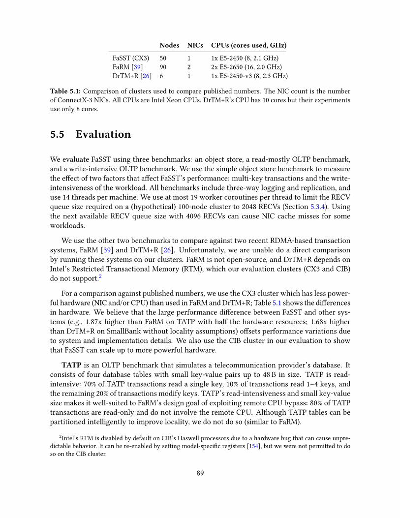
Nodes NICs CPUs (cores used, GHz)
FaSST (CX3) 50 1 1x E5-2450 (8, 2.1 GHz)FaRM [39] 90 2 2x E5-2650 (16, 2.0 GHz)DrTM+R [26] 6 1 1x E5-2450-v3 (8, 2.3 GHz)
Table 5.1: Comparison of clusters used to compare published numbers. The NIC count is the numberof ConnectX-3 NICs. All CPUs are Intel Xeon CPUs. DrTM+R’s CPU has 10 cores but their experimentsuse only 8 cores.
5.5 Evaluation
We evaluate FaSST using three benchmarks: an object store, a read-mostly OLTP benchmark,and a write-intensive OLTP benchmark. We use the simple object store benchmark to measurethe e�ect of two factors that a�ect FaSST’s performance: multi-key transactions and the write-intensiveness of the workload. All benchmarks include three-way logging and replication, anduse 14 threads per machine. We use at most 19 worker coroutines per thread to limit the RECVqueue size required on a (hypothetical) 100-node cluster to 2048 RECVs (Section 5.3.4). Usingthe next available RECV queue size with 4096 RECVs can cause NIC cache misses for someworkloads.
We use the other two benchmarks to compare against two recent RDMA-based transactionsystems, FaRM [39] and DrTM+R [26]. Unfortunately, we are unable do a direct comparisonby running these systems on our clusters. FaRM is not open-source, and DrTM+R depends onIntel’s Restricted Transactional Memory (RTM), which our evaluation clusters (CX3 and CIB)do not support.2
For a comparison against published numbers, we use the CX3 cluster which has less power-ful hardware (NIC and/or CPU) than used in FaRM and DrTM+R; Table 5.1 shows the di�erencesin hardware. We believe that the large performance di�erence between FaSST and other sys-tems (e.g., 1.87x higher than FaRM on TATP with half the hardware resources; 1.68x higherthan DrTM+R on SmallBank without locality assumptions) o�sets performance variations dueto system and implementation details. We also use the CIB cluster in our evaluation to showthat FaSST can scale up to more powerful hardware.
TATP is an OLTP benchmark that simulates a telecommunication provider’s database. Itconsists of four database tables with small key-value pairs up to 48 B in size. TATP is read-intensive: 70% of TATP transactions read a single key, 10% of transactions read 1–4 keys, andthe remaining 20% of transactions modify keys. TATP’s read-intensiveness and small key-valuesize makes it well-suited to FaRM’s design goal of exploiting remote CPU bypass: 80% of TATPtransactions are read-only and do not involve the remote CPU. Although TATP tables can bepartitioned intelligently to improve locality, we do not do so (similar to FaRM).
2Intel’s RTM is disabled by default on CIB’s Haswell processors due to a hardware bug that can cause unpre-dictable behavior. It can be re-enabled by setting model-speci�c registers [154], but we were not permitted to doso on the CIB cluster.
89
SmallBank is a simple OLTP benchmark that simulates bank account transactions. Small-Bank is write-intensive: 85% of transactions update a key. Our implementation of SmallBankdoes not assume data locality. In DrTM+R, however, single-account transactions (comprising60% of the workload) are initiated on the server hosting the key. Similarly, only a small fraction(< 10%) of transactions that access two accounts access accounts on di�erent machines. Theseassumptions make the workload well-suited to DrTM+R’s design goal of optimizing local trans-actions by using hardware transactional memory, but they save messages during transactionexecution and commit. We do not make either of these assumptions and use randomly chosenaccounts in all transactions.
Although the TPC-C benchmark [148] is a popular choice for evaluating transaction sys-tems, we chose not to include it in our benchmarks for two reasons. First, TPC-C has a highdegree of locality: only around 10% of transactions (1% of keys) access remote partitions. Thespeed of local transactions and data access, which our work does not focus on, has a large im-pact on TPC-C performance. Second, comparing performance across TPC-C implementationsis di�cult. This is due to di�erences in data structures (e.g., using hash tables instead of B-Trees for some tables), interaction of the benchmark with system optimizations (e.g., FaRM andDrTM+R use caching to reduce READs, but do not specify cache hit rates), and contention level.For example, DrTM+R uses one TPC-C “warehouse” per thread whereas FaRM uses ≈ 7, whichmay reduce contention.
5.5.1 Performance for an object store
We create an object store with small objects with 8 B keys and 40 B values. We scale the databaseby using 1 million keys per thread in the cluster. We use workloads with di�erent read andwrite set sizes to evaluate di�erent aspects of FaSST. We denote an object store workload inwhich transactions read r keys, and update w of these keys (on average) by O (r ,w ); we useO (1, 0), O (4, 0), and O (4, 2) to evaluate single-key read-only transactions, multi-key read-onlytransactions, and multi-key read-write transactions. All workloads choose keys uniformly atrandom; to avoid RPC-level coalescing, we choose keys such that their primaries are on di�erentmachines. Figure 5.7 shows FaSST’s performance on the object store workloads.
5.5.1.1 Single-key read-only transactions
With O (1, 0) FaSST achieves 11.0 million transactions per second (Mtps) per machine on CX3.FaSST is bottlenecked by the ConnectX-3 NIC: this throughput corresponds to 11.0 millionRPC requests per second (Mrps), which is 96.5% of the NIC’s maximum RPC throughput in thisscenario.
On CIB, FaSST achieves 32.3 Mtps/machine and is CPU-limited. This is becauseO (1, 0) doesnot allow Doorbell batching for requests, leading to low per-core throughput. Although CIB’sCPUs can saturate the NIC without request Doorbell batching for an RPC microbenchmark
90

0.1
1
10
100
CX3 (50 nodes) CIB (11 nodes)Mtp
s an
d M
rps
per m
achi
ne
O(1, 0) MtpsO(1, 0) req rate
O(4, 0) Mtps
O(4, 0) req rateO(4, 2) Mtps
O(4, 2) req rate
11.0
32.3
11.0
32.3
1.5
4.7
12.1
37.9
.78
2.3
10.9
32.1
Figure 5.7: Object store performance. The solid and patterned bars show transaction throughput andRPC request rate, respectively. The Y axis is in log scale.
that requires little computation (Section 5.2.3.1), they cannot do so for O (1, 0) which requireskey-value store accesses.
Comparison. FaRM [39] reports performance for the O (1, 0) workload. FaRM uses larger,16 B keys and 32 B values. Our FaSST implementation currently supports only 8 B keys, but weuse larger, 40 B values to keep the key-value item size identical. Using 16 B keys is unlikely tochange our results.3
FaRM achieves 8.77 Mtps/machine on a 90-node cluster with O (1, 0). It does not saturateits two ConnectX-3 NICs and is instead bottlenecked by its 16 CPU cores. FaSST achieves1.25x higher per-machine throughput with 50 nodes on CX3, which has close to half of FaRM’shardware resources per node (Table 5.1). Although O (1, 0) is well-suited to FaRM’s design goalof remote CPU bypass (i.e., no transaction involves the remote CPU), FaRM performs worse thanFaSST.Note that with FaRM’s hardware—two ConnectX-3 NICs and 16 cores—FaSST will deliverhigher performance; based on our CIB results, we expect FaSST to saturate the two ConnectX-3NICs and outperform FaRM by 2.5x.
5.5.1.2 Multi-key transactions
With multi-key transactions, FaSST reduces per-message CPU use by using Doorbell batch-ing for requests. With O (4, 0), FaSST achieves 1.5 and 4.7 Mtps/machine on CX3 and CIB,respectively. (The decrease in Mtps from O (1, 0) is because the transactions are larger.) Simi-lar to O (1, 0), FaSST is NIC-limited on CX3. On CIB, however, although FaSST is CPU-limitedwithO (1, 0), it becomes NIC-limited withO (4, 0). WithO (4, 0) on CIB, each machine generates37.9 Mrps on average, which matches the peak RPC throughput achievable with a request batchsize of 4.
3On a single node, FaSST’s data store (MICA) delivers similar GET throughput (within 3%) for these two key-value size con�gurations. Throughput is higher with 16 B keys, which could be because MICA’s hash functionuses fewer cycles.
91

0
50
100
150
200
0 5 10 15 20 25 30 35 40 45 50To
tal M
tps
Number of machines
CIBCX3
Figure 5.8: TATP throughput
With multi-key read-write transactions inO (4, 2), FaSST achieves 0.78 and 2.3 Mtps/machineon CX3 and CIB, respectively. FaSST is NIC-limited on CX3. On CIB, the bottleneck shifts toCPU again because key-value store inserts into the replicas’ data stores are slower than lookups.
Comparison. FaRM does not report object store results for multi-key transactions. However,as FaRM’s connected transport does not bene�t from Doorbell batching, we expect the gapbetween FaSST’s and FaRM’s performance to increase. For example, while FaSST’s RPC requestrate increases from 32.3 Mrps withO (1, 0) to 37.9 Mrps withO (4, 0), the change in FaRM’s READrate is likely to be negligible.
5.5.2 Performance on the TATP benchmark
We scale the TATP database size by using one million TATP “subscribers” per machine in thecluster. We use all CPU cores on each cluster and increase the number of machines to mea-sure the e�ect of scaling. Figure 5.8 shows the throughput on our clusters. On CX3, FaSSTachieves 3.6 Mtps/machine with 3 nodes (the minimum required for 3-way replication), and3.55 Mtps/machine with 50 nodes. On CIB, FaSST’s throughput increases to 8.7 Mtps/machinewith 3–11 nodes. In both cases, FaSST’s throughput scales linearly with cluster size.
Comparison. FaRM [39] reports 1.55 Mtps/machine for TATP on a 90-node cluster. With asmaller 50-node cluster, however, FaRM achieves higher throughput (≈ 1.9 Mtps/machine) [1].On 50 nodes on CX3, FaSST’s throughput is 87% higher. Compared toO (1, 0), the TATP perfor-mance di�erence between FaSST and FaRM is higher. TATP’s write transactions require usingFaRM’s RPCs, which deliver 4x lower throughput than FaRM’s one-sided READs, and up to 8xlower throughput than FaSST’s RPCs (Section 5.3.5).
5.5.3 Performance on the SmallBank benchmark
To scale the SmallBank database, we use 100,000 bank accounts per thread. 4% of the totalaccounts are accessed by 90% of transactions. (Despite the skew, the workload does not have
92

0
20
40
60
80
100
0 5 10 15 20 25 30 35 40 45 50To
tal M
tps
Number of machines
CIBCX3
Figure 5.9: FaSST’s SmallBank throughput
signi�cant contention due to the large number of threads, and therefore “bank accounts” in theworkload/cluster.) This con�guration is the same as in DrTM [154]. Figure 5.9 shows FaSST’sperformance on our clusters. FaSST achieves 1.57–1.71 Mtps/machine on CX3, and 4.2–4.3Mtps/machine on CIB, and scales linearly with cluster size.
Comparison. DrTM+R [26] achieves 0.93 Mtps/machine on a cluster similar to CX3 (Ta-ble 5.1), but with more powerful CPUs. FaSST outperforms it by over 1.68x on CX3, and over4.5x on CIB. DrTM+R’s lower performance comes from three factors. First, DrTM+R’s use ofRDMA’s atomic operations lead to a fundamentally slower protocol. For example, excludinglogging and replication, for a write-set key, DrTM+R uses four separate messages to read, lock,update, and unlock the key; FaSST uses only two messages. Second, as discussed in Guide-line 3.7.2, RDMA’s atomic operations perform poorly (up to 10x worse than READs) on theConnectX-3 NICs used in DrTM+R; evaluation on Connect-IB NICs may yield better perfor-mance, but is unlikely to outperform FaSST because of the more expensive protocol. Third,DrTM+R does not use connection sharing, so their reported performance may be a�ected byNIC cache misses.
5.5.4 Transaction latency on TATP
For brevity, we discuss FaSST’s latency only for TATP on CIB. Figure 5.10 shows FaSST’s medianand 99th percentile latency for successfully committed TATP transactions. To plot a throughput-latency graph, we vary the request load by increasing the number of worker coroutines perthread from 1 to 19; each machine runs 14 threads throughout. With one worker coroutineper thread, the total transaction throughput is 19.7 Mtps with 2.8 µs median latency and 21.8 µs99th percentile latency. Since over 50% of committed transactions in TATP are single-key reads,FaSST’s median latency at low load is close to the network’s RTT. This shows that our batchingoptimizations do not add noticeable latency. With 19 worker coroutines per thread, clusterthroughput increases to 95.7 Mtps, and median and 99th percentile latency increase to 12.6 µsand 87.2 µs, respectively.
93
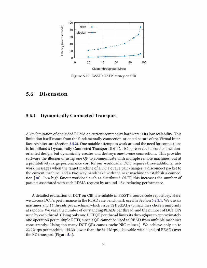
0
20
40
60
80
100
0 20 40 60 80 100La
tenc
y (m
icro
seco
nds)
Cluster throughput (Mrps)
99th
Median
Figure 5.10: FaSST’s TATP latency on CIB
5.6 Discussion
5.6.1 Dynamically Connected Transport
A key limitation of one-sided RDMA on current commodity hardware is its low scalability. Thislimitation itself comes from the fundamentally connection-oriented nature of the Virtual Inter-face Architecture (Section 3.5.2). One notable attempt to work around the need for connectionsis In�niBand’s Dynamically Connected Transport (DCT). DCT preserves its core connection-oriented design, but dynamically creates and destroys one-to-one connections. This providessoftware the illusion of using one QP to communicate with multiple remote machines, but ata prohibitively large performance cost for our workloads: DCT requires three additional net-work messages when the target machine of a DCT queue pair changes: a disconnect packet tothe current machine, and a two-way handshake with the next machine to establish a connec-tion [30]. In a high fanout workload such as distributed OLTP, this increases the number ofpackets associated with each RDMA request by around 1.5x, reducing performance.
A detailed evaluation of DCT on CIB is available in FaSST’s source code repository. Here,we discuss DCT’s performance in the READ rate benchmark used in Section 5.2.3.1. We use sixmachines and 14 threads per machine, which issue 32 B READs to machines chosen uniformlyat random. We vary the number of outstanding READs per thread, and the number of DCT QPsused by each thread. (Using only one DCT QP per thread limits its throughput to approximatelyone operation per multiple RTTs, since a QP cannot be used to READ from multiple machinesconcurrently. Using too many DCT QPs causes cache NIC misses.) We achieve only up to22.9 Mrps per machine—55.3% lower than the 51.2 Mrps achievable with standard READs overthe RC transport (Figure 5.1).
94
5.6.2 Comparison with hybrid RPC-RDMA approaches
FaSST takes an extreme approach took by using only RPCs, demonstrating that high-performancetransactions do not necessarily require CPU bypass, and that a design using optimized RPCs canprovide better performance. It might seem that if scalable one-sided RDMA becomes commonlyavailable in the future, the highest-performing design will likely be hybrid of RPCs and remotebypass, with RPCs used for accessing data structures during transaction execution, and scalableone-sided writes used for logging and replication during transaction commit. Wei et al. [155]design such a hybrid transaction processing system called RTX. However, FaSST’s RPC-onlydesign outperforms RTX’s hybrid design.
In the evaluation results reported by Wei et al. [155], RTX outperforms a highly-modi�edversion of FaSST that uses RTX’s transaction protocol. RTX’s protocol was designed with one-sided RDMA in mind; it is less e�cient than FaSST’s original protocol, which bene�ts fromthe general-purpose computation ability of CPUs. For example, FaSST’s original protocol canread and lock a remote object in a transaction’s write set in one RPC, whereas RTX’s version ofFaSST does so in two RPCs, emulating the two one-sided RDMA operations (RDMA read andatomic compare-and-swap) used in RTX’s protocol. FaSST’s original design and implementa-tion outperforms RTX. On the SmallBank benchmark, FaSST achieves 4.2 Mtps per machine onCIB, whereas RTX achieves 2.85 Mtps per machine with similar CPU and NIC resources.4
In addition, remote-bypassing designs will have higher software complexity than RPC-onlydesigns. For example, writing durably to remote non-volatile memory with RDMA writes ischallenging [104].
5.6.3 Advanced one-sided RDMA
Future NICs may provide advanced one-sided RDMA operations such as multi-address atomicoperations, and B-Tree traversals [132]. Both of these operations require multiple PCIe roundtrips, and will face similar �exibility and performance problems as one-sided RDMA (but overthe PCIe bus) if used for high-performance distributed transactions. On the other hand, webelieve that “CPU onload” networks such as Intel’s 100 Gbps OmniPath [19] are well-suited fortransactions. These networks provide fast messaging over a reliable link layer, but not one-sidedRDMA, and are therefore cheaper than “NIC o�oad” networks such as Mellanox’s In�niBand.FaSST requires only messaging, so we expect our design to work well over OmniPath.
4RTX uses platforms with two CPUs and two NICs each. Because their evaluation isolates processes to onesocket, we regard each platform as two machines, each of which has a similarly-powerful CPU and NIC as our CIBcluster.
95
5.7 Related work on distributed transactions
Like FaSST, FaRM uses primary-backup replication and optimistic concurrency control for trans-actions. FaRM’s design (unlike FaSST) is specialized to work with their desire to use one-sidedRDMA verbs. FaRM also provides fast failure detection and recovery, and a sophisticated pro-gramming model, which was not a goal of our work on FaSST. Several projects use one-sidedRDMA atomics for transactions [17, 26, 154]. Though an attractive primitive, RDMA atomicscan reduce performance because of in-NIC lock contention (Guideline 3.7.2), use of connectedQPs, and additional round trips compared to an RPC-based approach (e.g., separate messages areneeded to read and lock a key). Calvin [145] uses conventional networking without kernel by-pass, and is designed around avoiding distributed commit. Designs that use fast networks, how-ever, can use traditional distributed commit protocols to achieve high performance [39, 154].
5.8 Conclusion
FaSST is a high-performance, scalable, distributed in-memory transaction processing systemthat provides serializability and durability. FaSST achieves its performance using FaSST RPCs,a new RPC design tailored to the properties of modern datacenter networks. It rejects RDMA’sCPU bypass feature to keep its communication overhead low and its system design fast, �exible,scalable, and simple. FaSST outperforms recent transactional systems that use one-sided RDMAby 1.68x–1.87x with fewer resources and making fewer workload assumptions. Finally, weprovide the �rst large-scale study of In�niBand network reliability, demonstrating the rarity ofpacket loss on such networks.
Our experience with FaSST led to two insights that form the basis of eRPC. First, since RPCsperform well in lossless networks with zero packet loss, they should also perform well most ofthe time in lossy networks, if we can somehow make packet loss rare. Second, since RPCsperform well with small messages and short-running handlers—which are workload character-istics of our target datacenter applications—perhaps we can provide good performance for thesecommon-case workloads, while also supporting large messages and long-running handlers inless common cases. Combined, these insights lead to eRPC’s end-to-end design that does notdepend on in-network features, and eRPC’s CPU-e�cient support of a large, general-purposefeature set.
96
“Using performance to justify placing functions in a low-levelsubsystem must be done carefully. Sometimes, by examining theproblem thoroughly, the same or better performance can beachieved at the high level.”
End-to-end Arguments in System Design
Chapter 6
eRPC: A Fast and General-purpose RPC Library
This chapter presents the concluding RPC design of this thesis: eRPC. We build on top of resultsfrom previous chapters with a new understanding of packet loss and congestion control indatacenters to create an end-to-end design with a general-purpose feature set, while preservingspeed close to HERD and FaSST RPCs. Unlike our prior RPC designs, eRPC does not dependon any in-network features; it works well with only UDP packets over lossy Ethernet withoutPriority Flow Control. eRPC adds support for a general-purpose feature set that is su�cient tobuild real applications, including support for congestion control, large messages, long-runningrequest handlers, and node failures. In the past, researchers have hypothesized that supportingthese features in software instead of NIC hardware would result in performance substantiallylower than FaSST RPCs [40]. We show that with careful design, we can support all these featuresand still match FaSST’s performance.
eRPC has two key insights. First, we optimize for common-case workloads and networkconditions, i.e., when messages are small and RPC handlers are short (Section 2.2.4), and thenetwork is congestion-free. Handling large messages, long-running RPC handlers, and networkcongestion requires expensive code paths, which eRPC avoids whenever possible. Several eRPCcomponents, including its API, message format, and wire protocol are optimized for the com-mon case. Second, we show that restricting each �ow to at most one bandwidth-delay product(BDP) of outstanding data e�ectively prevents packet loss caused by switch bu�er over�ow forcommon tra�c patterns. This is because datacenter switch bu�ers are much larger than thenetwork’s BDP. For example, in our two-layer testbed that resembles real deployments, eachswitch has 12 MB of dynamic bu�er, while the BDP is only 19 kB.
Our contributions in this chapter are:
1. We describe the design and implementation of a high-performance, general-purpose RPClibrary for datacenter networks that performs well in three key metrics: message ratefor small messages, bandwidth for large messages, and scalability to a large number ofnodes and CPU cores. This includes (1) common-case optimizations that improve eRPC’sperformance for our target workloads by up to 66%; (2) techniques that enable zero-copytransmission in the presence of retransmissions, node failures, and rate limiting; and (3) a
97

scalable implementation whose NIC memory footprint is independent of the number ofnodes in the cluster.
2. We are the �rst to show experimentally that, with well-designed end-host networkingsoftware, lossy networks can provide state-of-the-art networking performance. We showthat eRPC performs well in a 100-node cluster with lossy Ethernet without PFC. Our mi-crobenchmarks on two lossy Ethernet clusters show that eRPC can: (1) provide 2.3 µs me-dian RPC latency; (2) handle up to 10 million RPCs per second with one core; (3) transferlarge messages at 75 Gbps with one core; (4) maintain low switch queueing during in-cast; and (5) maintain peak performance with 20000 connections per node (two millionconnections cluster-wide).
3. We show that eRPC can be used as a high-performance drop-in networking library forexisting software. Notably, we implement a replicated in-memory key-value store witha production-grade version of Raft [23, 121] that is used in Intel’s distributed objectstore [36] without modifying the Raft source code. Our three-way replication latencyon lossy Ethernet is 5.5 µs, which is competitive with existing specialized systems thatuse programmable switches (NetChain [76]), FPGAs [72], and RDMA (DARE [129]).
6.1 Understanding packet loss in datacenter networks
The RPC designs in HERD and FaSST rely on a lossless link layer to avoid dealing with packetloss in an end-to-end fashion in software. Unfortunately, network losslessness comes with sev-eral drawbacks, including deadlocks, unfairness, and operational complexity (Section 2.1.3.2).eRPC uses new insights about packet loss in datacenter networks to provide high performancewithout in lossy networks: We found that because datacenter switch bu�ers vastly exceed theirnetwork’s BDP, restricting each �ow to one BDP of outstanding data prevents most packet dropseven on lossy networks.
Switch bu�ers in Ethernet datacenters. The increase in datacenter network bandwidthhas been accompanied by a corresponding decrease in round-trip time (RTT), resulting in asmall BDP. Switch bu�ers have grown in size, to the point where “shallow-bu�ered” switchesthat use SRAM for bu�ering now provide tens of megabytes of shared bu�er. Much of thisbu�er is dynamic, i.e., it can be dedicated to an incast’s target port, preventing packet dropsfrom bu�er over�ow. For example, in our two-layer 25 GbE CX4 cluster that resembles realdatacenters (Table 2.2), the RTT between two nodes connected to di�erent top-of-rack switchesis 6 µs, so the BDP is 19 kB. This is unsurprising: for example, the BDP of the two-tier 10 GbEdatacenter used in pFabric is 18 kB [6].
In contrast to the small BDP (∼10 kB), switches have tens of megabytes of bu�er. For ex-ample, the Mellanox Spectrum switches in CX4 have 12 MB in their dynamic bu�er pool [75].Therefore, the ToR switch can ideally tolerate a 640-way incast. The popular Broadcom Trident-II chip used in datacenters at Microsoft and Facebook has a 9 MB dynamic bu�er [43, 165].Zhang et al. [161] have made a similar observation (i.e., bu�er� BDP) for gigabit Ethernet.
98

In practice, we wish to support approximately 50-way incasts: congestion control proto-cols deployed in real datacenters are tested against comparable incast degrees. For example,DCQCN and Timely use up to 20- and 40-way incasts, respectively [115, 165]. This is muchsmaller than 640, allowing substantial tolerance to technology variations, i.e., we expect theswitch bu�er to be large enough to prevent most packet drops in datacenters with di�erentBDPs and switch bu�er sizes. Nevertheless, it is unlikely that the BDP-to-bu�er ratio will growsubstantially in the near future: newer 100 GbE switches have even larger bu�ers (42 MB inMellanox’s Spectrum-2 and 32 MB in Broadcom’s Trident-III), and NIC-added latency is contin-uously decreasing. For example, we measured In�niBand’s RTT between nodes under di�erentToR’s to be only 3.1 µs, and Ethernet has historically caught up with In�niBand’s performance.
6.2 eRPC overview
This section provides an overview of the interface that eRPC provides to developers, i.e., itsAPI and threading model. While FaSST RPCs provide an interface specialized for transactionsin OLTP systems, eRPC provides a general-purpose and more convenient interface. For exam-ple, we forego coroutines, and instead use event-loop based concurrency, which is easier toaccommodate in existing codebases. And, eRPC provides the ability to run long-running RPChandlers in “worker” threads.
Similar to FaSST, eRPC implements RPCs on top of a transport layer that provides basicunreliable packet I/O, such as UDP over Ethernet, or In�niBand’s Unreliable Datagram trans-port. It requires a userspace NIC driver for good performance. eRPC’s primary contributionis the design and implementation of end-host mechanisms and a network transport (e.g., wireprotocol and congestion control) that support the RPC interface.
6.2.1 RPC API
RPCs execute at most once, and are asynchronous to avoid stalling on network round trips;intra-thread concurrency is provided using an event loop. RPC servers register request handlerfunctions with unique request types; clients use these request types when issuing RPCs, andget continuation callbacks on RPC completion. Users store RPC messages in opaque, DMA-capable bu�ers provided by eRPC, called msgbufs; a library that provides marshalling and un-marshalling can be used as a layer on top of eRPC.
Each user thread that sends or receives RPCs creates an exclusive Rpc endpoint (a C++object). Each Rpc endpoint contains an RX and TX queue for packet I/O, an event loop, andseveral sessions. A session is a one-to-one connection between two Rpc endpoints, i.e., two userthreads. The client endpoint of a session is used to send requests to the user thread at the otherend. A user thread may participate in multiple sessions, possibly playing di�erent roles (i.e.,client or server) in di�erent sessions.
99

User threads act as “dispatch” threads: they must periodically run their Rpc endpoint’s eventloop to make progress. The event loop performs the bulk of eRPC’s work, including packet I/O,congestion control, and management functions. It invokes request handlers and continuations,and dispatches long-running request handlers to worker threads (§ 6.2.2).
Client control �ow. rpc->enqueue_request() queues a request msgbuf on a session, whichis transmitted when the user runs rpc’s event loop. On receiving the response, the event loopcopies it to the client’s response msgbuf and invokes the continuation callback.
Server control �ow. The event loop of the Rpc that owns the server session invokes (or dis-patches) a request handler on receiving a request. We allow nested RPCs, i.e., the handler neednot enqueue a response before returning. It may issue its own RPCs and call enqueue_response()for the �rst request later when all dependencies complete.
6.2.2 Worker threads
A key design decision for an RPC system is which thread runs an RPC handler. Some RPCsystems such as RAMCloud use dispatch threads for only network I/O. RAMCloud’s dispatchthreads communicate with worker threads that run request handlers. At datacenter networkspeeds, however, inter-thread communication is expensive: it reduces throughput and adds upto 400 ns to request latency [124]. Other RPC systems such as FaRM, and FaSST and HERDRPCs, avoid this overhead by running all request handlers directly in dispatch threads. Thislatter approach su�ers from two drawbacks when executing long request handlers: First, suchhandlers block other dispatch processing, increasing tail latency. Second, they prevent rapidserver-to-client congestion feedback, since the server might not send packets while runninguser code.
Striking a balance, eRPC allows running request handlers in both dispatch threads andworker threads: When registering a request handler, the programmer speci�es whether thehandler should run in a dispatch thread. This is the only additional user input required ineRPC. In typical use cases, handlers that require up to a few hundred nanoseconds use dispatchthreads, and longer handlers use worker threads.
6.2.3 Evaluation clusters
We evaluate eRPC on the CX3, CX4, and CX5 clusters (Table 2.2), covering both lossy Ether-net and lossless In�niBand networks. eRPC works well on all three clusters, showing that ourdesign is robust to NIC and network technology changes. We use traditional UDP on the Ether-net clusters (i.e., we do not use RoCE), and In�niBand’s Unreliable Datagram transport on theIn�niBand cluster.
Currently, eRPC is primarily optimized for Mellanox NICs. eRPC also works with DPDK-capable NICs that support �ow steering. For Mellanox Ethernet NICs, we generate UDP packets
100
directly with libibverbs instead of going through DPDK, which internally uses libibverbsfor these NICs.
Our evaluation primarily uses the large CX4 cluster, which resembles real-world datacen-ters. The ConnectX-4 NICs used in CX4 are widely deployed in datacenters at Microsoft andFacebook [3, 165], and its Mellanox Spectrum switches perform similarly to Broadcom’s Tridentswitches used in these datacenters (i.e., both switches provide dynamic bu�ering, cut-throughswitching, and less than 500 ns port-to-port latency.) Because CX4 is shared with other Cloud-Lab users, we use up to 100 nodes out of its 200 nodes. The six switches in CX4 are organizedas �ve ToRs with 40 25 GbE downlinks and �ve 100 GbE uplinks, for a 2:1 oversubscription.
6.3 eRPC design
Achieving eRPC’s performance goals requires careful design and implementation. We discussthree aspects of eRPC’s design in this section: scalability of our networking primitives, the chal-lenges involved in supporting zero-copy, and the design of sessions. The next section discusseseRPC’s wire protocol and congestion control. A recurring theme in eRPC’s design is that weoptimize for the common case, i.e., when request handlers run in dispatch threads, RPCs aresmall, and the network is congestion-free.
6.3.1 Scalability considerations
We chose plain packet I/O instead of RDMA writes to send messages in eRPC. This decisionis based on two insights. First, the connection-oriented nature of one-sided RDMA reducesscalability. eRPC replaces NIC-managed connection state with CPU-managed connection state.This is an explicit design choice, based upon fundamental di�erences between CPU and NICarchitectures (Guideline 3.5.2).
Second, RPC systems that use RDMA writes, such as HERD and FaRM’s RPCs, have an-other fundamental scalability limitation. In these systems, clients write requests directly toper-client circular bu�ers in the server’s memory; the server must poll these bu�ers to detectnew requests. The number of circular bu�ers grows with the number of clients, limiting scala-bility.
With traditional userspace packet I/O, the NIC writes an incoming packet’s payload to abu�er speci�ed by a descriptor pre-posted to the NIC’s RX queue (RQ) by the receiver host; thepacket is dropped if the RQ is empty. Then, the NIC writes an entry to the host’s RX completionqueue. The receiver host can then check for received packets in constant time by examiningthe head of the completion queue.
To avoid dropping packets due to an empty RQ with no descriptors, RQs must be sizedproportionally to the number of independent connected RPC endpoints (§ 6.3.3.1). Older NICsexperience cache thrashing with large RQs, thus limiting scalability, but we �nd that newer
101
NICs fare better: While a Connect-IB NIC could support only 14 2K-entry RQs before thrashing(Section 5.5), we �nd that ConnectX-5 NICs do not thrash even with 28 64K-entry RQs. Thisimprovement is due to more intelligent prefetching and caching of RQ descriptors, instead of amassive 64x increase in NIC cache.
We use features of current NICs (e.g., multi-packet RQ descriptors that identify several con-tiguous packet bu�ers) in novel ways to guarantee a constant NIC memory footprint per CPUcore, i.e., it does not depend on the number of nodes in the cluster. This result can simplify thedesign of future NICs (e.g., RQ descriptor caching is unneeded), but its current value is limitedto performance improvements because current NICs support very large RQs, and are perhapsoverly complex as a result.
Primarily, four on-NIC structures contribute to eRPC’s NIC memory footprint: the TX andRX queues, and their corresponding completion queues. The TX queue must allow su�cientpipelining to hide PCIe latency; we found that 64 entries are su�cient in all cases. eRPC’s TXqueue and TX completion queue have 64 entries by default, so their footprint does not depend oncluster size. The footprint of on-NIC page table entries required for eRPC is negligible becausewe use 2 MB hugepages [38].
As we discuss in Section 6.3.3.1, eRPC’s RQs must have su�cient descriptors for all con-nected sessions. The footprint of traditional RQs grows with the number of connected ses-sions that eRPC supports. Modern NICs (e.g., ConnectX-4 and newer NICs from Mellanox)support multi-packet RQ descriptors that specify multiple contiguous packet bu�ers using baseaddress, bu�er size, and number of bu�ers. With eRPC’s default con�guration of 512-way RQdescriptors, RQ size is reduced by 512x, making it negligible. This optimization has the addedadvantage of almost eliminating RX descriptor DMA, which is now needed only once every512 packets. While multi-packet RQs were originally designed for large receive o�oad of onemessage [111], we use this feature to receive packets of independent messages.
What about the RX completion queue (CQ)? By default, NICs expect the RX CQ to havesu�cient space for each received packet, so using multi-packet RQ descriptors does not reduceCQ size. However, eRPC does not need the information that the NIC DMA-writes to the RXCQ entries. It needs only the number of new packets received. Therefore, we shrink the CQby allowing it to overrun, i.e., we allow the NIC to overwrite existing entries in the CQ in around-robin fashion. We poll the overrunning CQ to check for received packets. It is possibleto use a RX CQ with only one entry, but we found that doing so causes cache line contentionbetween eRPC’s threads and the CPU’s on-die PCIe controller. We solve this issue by usingeight-entry CQs, which makes the contention negligible.
6.3.2 Challenges in zero-copy transmission
eRPC uses zero-copy packet I/O to provide performance comparable to low-level interfacessuch as DPDK and one-sided RDMA. This section describes the challenges involved in doingso.
102

H1 HNData1 DataNa bc
Data2 H2
Figure 6.1: Layout of packet headers and data for an N -packet msgbuf. Blue arrows show NIC DMAs;the letters show the order in which the DMAs are performed for packets 1 and N .
6.3.2.1 Message bu�er layout
eRPC provides DMA-capable message bu�ers to applications for zero-copy transfers. A msgbufholds one, possibly multi-packet message. It consists of per-packet headers and data, arrangedin a fashion optimized for small single-packet messages (Figure 6.1). Each eRPC packet has aheader that contains the network transport header, and eRPC metadata such as the request han-dler type and sequence numbers. We designed a msgbuf layout that satis�es two requirements.
1. The data region is contiguous to allow its use in applications as an opaque bu�er.
2. The �rst packet’s data and header are contiguous. This allows the NIC to fetch smallmessages with one DMA read; using multiple DMAs for small messages would substan-tially increase NIC processing and PCIe use, reducing message rate by up to 20% (Guide-line 3.6.3).
For multi-packet messages, headers for subsequent packets are at the end of the message:placing header 2 immediately after the �rst data packet would violate our �rst requirement.Non-�rst packets require two DMAs (header and data); this is reasonable because the overheadfor DMA-reading small headers is amortized over the large data DMA.
6.3.2.2 Message bu�er ownership
Since eRPC transfers packets directly from application-owned msgbufs, eRPC must never usea msgbuf reference after returning ownership of the reference to the application. For brevity,we discuss msgbuf ownership issues for only clients; the process is similar but simpler for theserver, since eRPC’s servers are passive (Section 6.4). At clients, we must ensure the followinginvariant: no eRPC transmission queue contains a reference to the request msgbuf when the re-sponse is processed. Processing the response includes invoking the continuation, which permitsthe application to reuse the request msgbuf. In eRPC, a request reference may be queued in theNIC’s hardware DMA queue, or in our software rate limiter (Section 6.4.2).
Maintaining this invariant is trivial when there are no retransmissions or node failures,since the request must exit all transmission queues before the response is received. The follow-ing example demonstrates the problem with retransmissions. Consider a client that falselysuspects packet loss and retransmits its request. The server, however, received the �rst copy ofthe request, and its response reaches the client before the retransmitted request is dequeued.Before processing the response and invoking the continuation, we must ensure that there areno queued references to the request msgbuf. We discuss our solution for the NIC DMA queueand the rate limiter next.
103
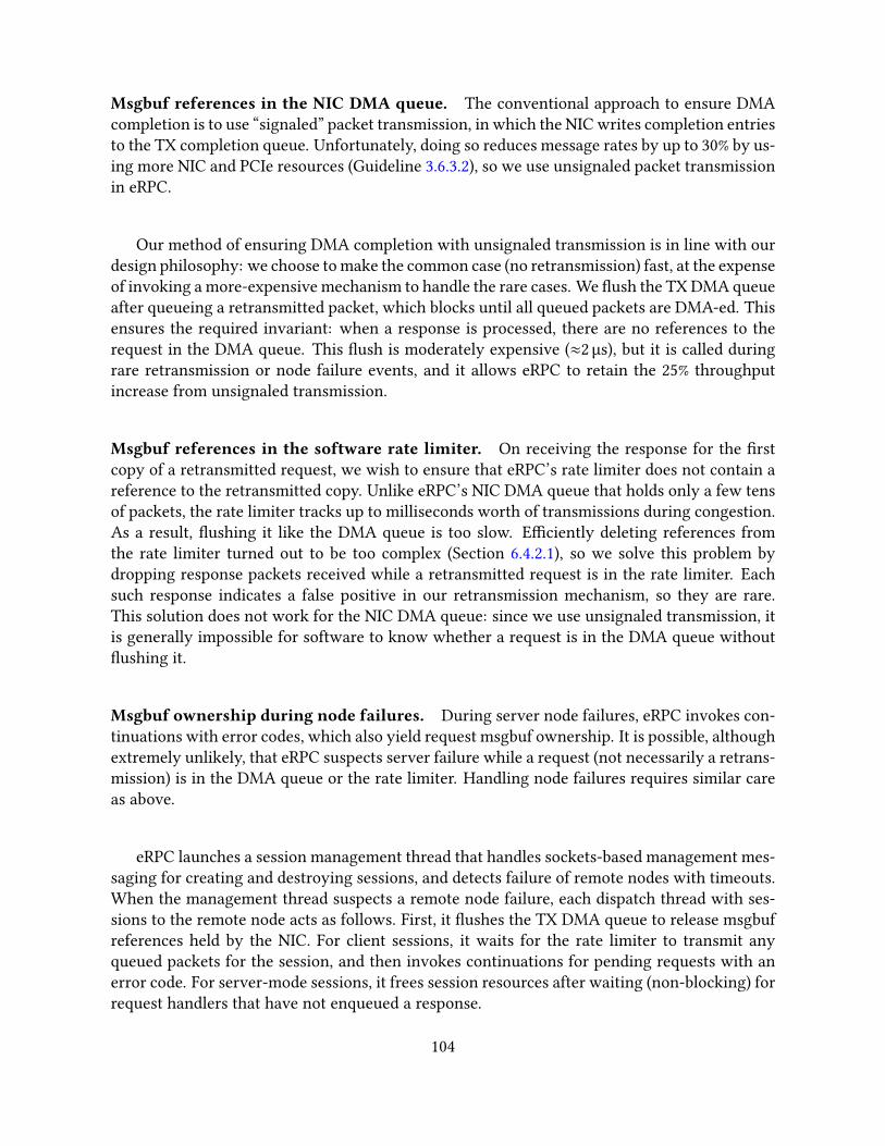
Msgbuf references in the NIC DMA queue. The conventional approach to ensure DMAcompletion is to use “signaled” packet transmission, in which the NIC writes completion entriesto the TX completion queue. Unfortunately, doing so reduces message rates by up to 30% by us-ing more NIC and PCIe resources (Guideline 3.6.3.2), so we use unsignaled packet transmissionin eRPC.
Our method of ensuring DMA completion with unsignaled transmission is in line with ourdesign philosophy: we choose to make the common case (no retransmission) fast, at the expenseof invoking a more-expensive mechanism to handle the rare cases. We �ush the TX DMA queueafter queueing a retransmitted packet, which blocks until all queued packets are DMA-ed. Thisensures the required invariant: when a response is processed, there are no references to therequest in the DMA queue. This �ush is moderately expensive (≈2 µs), but it is called duringrare retransmission or node failure events, and it allows eRPC to retain the 25% throughputincrease from unsignaled transmission.
Msgbuf references in the software rate limiter. On receiving the response for the �rstcopy of a retransmitted request, we wish to ensure that eRPC’s rate limiter does not contain areference to the retransmitted copy. Unlike eRPC’s NIC DMA queue that holds only a few tensof packets, the rate limiter tracks up to milliseconds worth of transmissions during congestion.As a result, �ushing it like the DMA queue is too slow. E�ciently deleting references fromthe rate limiter turned out to be too complex (Section 6.4.2.1), so we solve this problem bydropping response packets received while a retransmitted request is in the rate limiter. Eachsuch response indicates a false positive in our retransmission mechanism, so they are rare.This solution does not work for the NIC DMA queue: since we use unsignaled transmission, itis generally impossible for software to know whether a request is in the DMA queue without�ushing it.
Msgbuf ownership during node failures. During server node failures, eRPC invokes con-tinuations with error codes, which also yield request msgbuf ownership. It is possible, althoughextremely unlikely, that eRPC suspects server failure while a request (not necessarily a retrans-mission) is in the DMA queue or the rate limiter. Handling node failures requires similar careas above.
eRPC launches a session management thread that handles sockets-based management mes-saging for creating and destroying sessions, and detects failure of remote nodes with timeouts.When the management thread suspects a remote node failure, each dispatch thread with ses-sions to the remote node acts as follows. First, it �ushes the TX DMA queue to release msgbufreferences held by the NIC. For client sessions, it waits for the rate limiter to transmit anyqueued packets for the session, and then invokes continuations for pending requests with anerror code. For server-mode sessions, it frees session resources after waiting (non-blocking) forrequest handlers that have not enqueued a response.
104

6.3.2.3 Zero-copy request processing
Zero-copy reception is harder than transmission: To provide a contiguous request msgbuf tothe request handler at the server, we must strip headers from received packets, and copy onlyapplication data to the target msgbuf. However, we were able to provide zero-copy recep-tion for our common-case workload consisting of single-packet requests and dispatch-moderequest handlers as follows. eRPC owns the packet bu�ers DMA-ed by the NIC until it re-addsthe descriptors for these packets back to the receive queue (i.e., the NIC cannot modify thepacket bu�ers for this period.) This ownership guarantee allows running dispatch-mode han-dlers without copying the DMA-ed request packet to a dynamically-allocated msgbuf. Doingso improves eRPC’s message rate by up to 16% (Section 6.5.2).
6.3.3 Sessions
Each session maintains multiple outstanding requests to keep the network pipe full. Concur-rently requests on a session can complete out-of-order with respect to each other. This avoidsblocking dispatch-mode RPCs behind a long-running worker-mode RPC. We support a con-stant number of concurrent requests (default = 8) per session; eRPC queues additional requeststransparently. This is inspired by how RDMA connections allow a constant number of opera-tions [133]. A session uses an array of slots to track RPC metadata for outstanding requests.
Slots in server-mode sessions have an MTU-size preallocated msgbuf for use by requesthandlers that issue short responses. Using the preallocated msgbuf does not require user input:eRPC chooses it automatically at run time by examining the handler’s desired response size.This optimization avoids the overhead of dynamic memory allocation, and improves eRPC’smessage rate by up to 13% (§ 6.5.2).
6.3.3.1 Session credits
eRPC limits the number of unacknowledged packets on a session for two reasons. First, toavoid dropping packets due to an empty RQ with no descriptors, the number of packets thatmay be sent to an Rpc must not exceed the size of its RQ (|RQ |). Because each session sendspackets independently of others, we �rst limit the number of sessions that an Rpc can participatein. Each session then uses session credits to implement packet-level �ow control: we limit thenumber of packets that a client may send on a session before receiving a reply, allowing theserver Rpc to replenish used RQ descriptors before sending more packets.
Second, session credits automatically implement end-to-end �ow control, which reducesswitch queueing (§ 6.4.2). Allowing BDP/MTU credits per session ensures that each sessioncan achieve line rate. eRPC’s BDP �ow control is similar to the IRN proposal for RDMA NICsby Mittal et al. [116]. We compare eRPC to IRN in detail in Section 6.4.2.3.
A client session starts with a quota of C packets. Sending a packet to the server consumesa credit, and receiving a packet replenishes a credit. An Rpc can therefore participate in up to
105
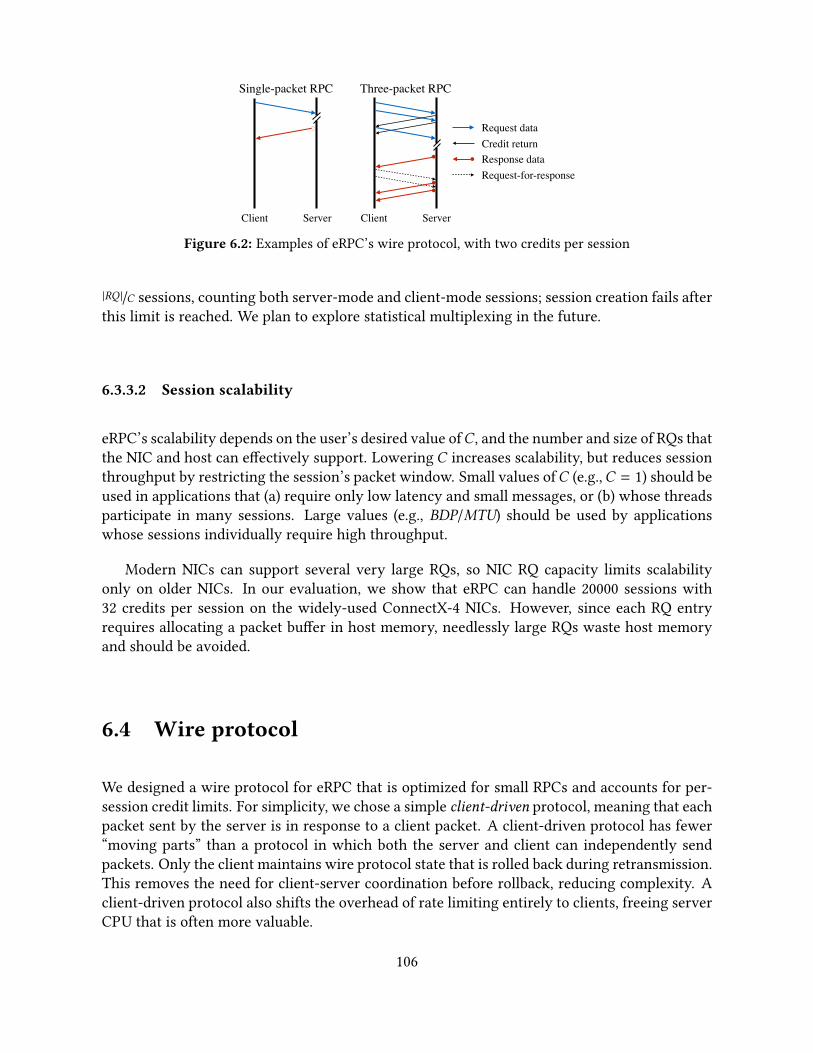
Client Server Client Server
Single-packet RPC Three-packet RPC
Credit returnRequest data
Response dataRequest-for-response
Figure 6.2: Examples of eRPC’s wire protocol, with two credits per session
|RQ |/C sessions, counting both server-mode and client-mode sessions; session creation fails afterthis limit is reached. We plan to explore statistical multiplexing in the future.
6.3.3.2 Session scalability
eRPC’s scalability depends on the user’s desired value ofC , and the number and size of RQs thatthe NIC and host can e�ectively support. Lowering C increases scalability, but reduces sessionthroughput by restricting the session’s packet window. Small values ofC (e.g.,C = 1) should beused in applications that (a) require only low latency and small messages, or (b) whose threadsparticipate in many sessions. Large values (e.g., BDP/MTU) should be used by applicationswhose sessions individually require high throughput.
Modern NICs can support several very large RQs, so NIC RQ capacity limits scalabilityonly on older NICs. In our evaluation, we show that eRPC can handle 20000 sessions with32 credits per session on the widely-used ConnectX-4 NICs. However, since each RQ entryrequires allocating a packet bu�er in host memory, needlessly large RQs waste host memoryand should be avoided.
6.4 Wire protocol
We designed a wire protocol for eRPC that is optimized for small RPCs and accounts for per-session credit limits. For simplicity, we chose a simple client-driven protocol, meaning that eachpacket sent by the server is in response to a client packet. A client-driven protocol has fewer“moving parts” than a protocol in which both the server and client can independently sendpackets. Only the client maintains wire protocol state that is rolled back during retransmission.This removes the need for client-server coordination before rollback, reducing complexity. Aclient-driven protocol also shifts the overhead of rate limiting entirely to clients, freeing serverCPU that is often more valuable.
106
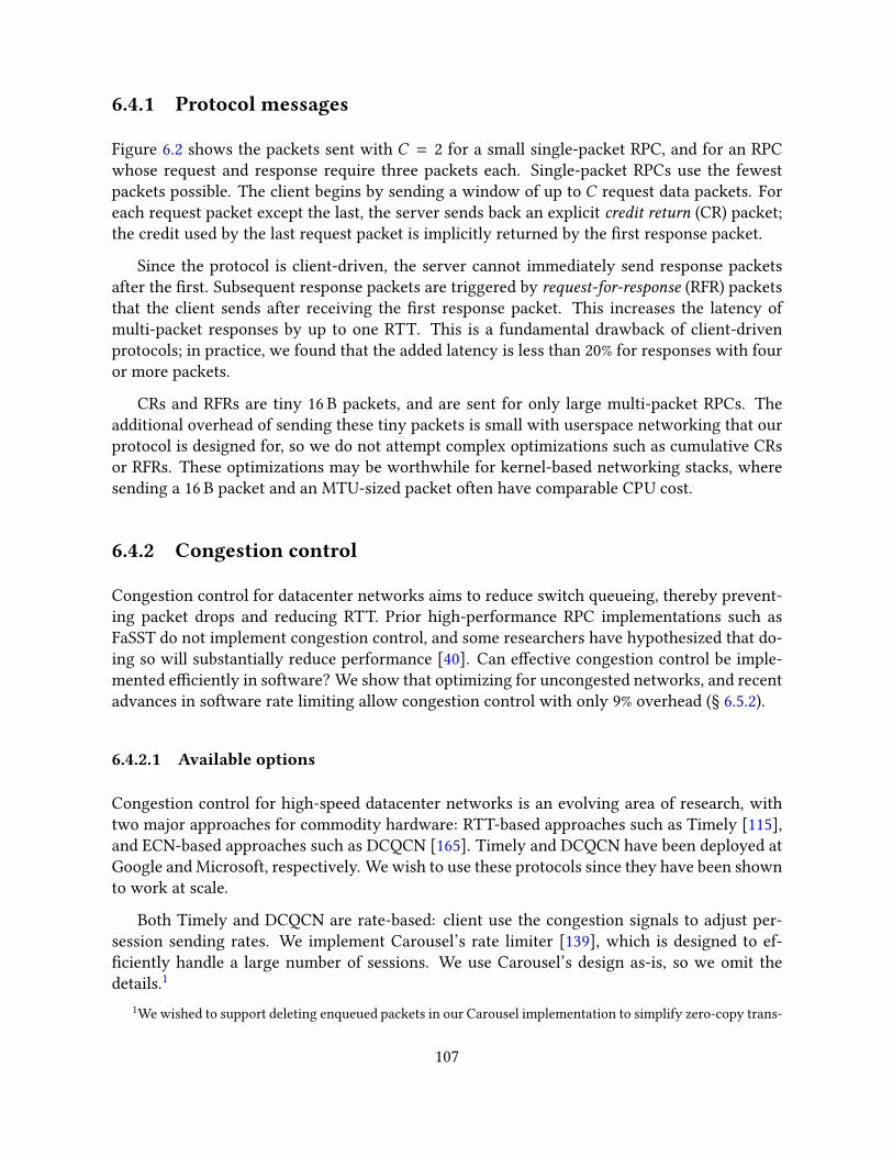
6.4.1 Protocol messages
Figure 6.2 shows the packets sent with C = 2 for a small single-packet RPC, and for an RPCwhose request and response require three packets each. Single-packet RPCs use the fewestpackets possible. The client begins by sending a window of up to C request data packets. Foreach request packet except the last, the server sends back an explicit credit return (CR) packet;the credit used by the last request packet is implicitly returned by the �rst response packet.
Since the protocol is client-driven, the server cannot immediately send response packetsafter the �rst. Subsequent response packets are triggered by request-for-response (RFR) packetsthat the client sends after receiving the �rst response packet. This increases the latency ofmulti-packet responses by up to one RTT. This is a fundamental drawback of client-drivenprotocols; in practice, we found that the added latency is less than 20% for responses with fouror more packets.
CRs and RFRs are tiny 16 B packets, and are sent for only large multi-packet RPCs. Theadditional overhead of sending these tiny packets is small with userspace networking that ourprotocol is designed for, so we do not attempt complex optimizations such as cumulative CRsor RFRs. These optimizations may be worthwhile for kernel-based networking stacks, wheresending a 16 B packet and an MTU-sized packet often have comparable CPU cost.
6.4.2 Congestion control
Congestion control for datacenter networks aims to reduce switch queueing, thereby prevent-ing packet drops and reducing RTT. Prior high-performance RPC implementations such asFaSST do not implement congestion control, and some researchers have hypothesized that do-ing so will substantially reduce performance [40]. Can e�ective congestion control be imple-mented e�ciently in software? We show that optimizing for uncongested networks, and recentadvances in software rate limiting allow congestion control with only 9% overhead (§ 6.5.2).
6.4.2.1 Available options
Congestion control for high-speed datacenter networks is an evolving area of research, withtwo major approaches for commodity hardware: RTT-based approaches such as Timely [115],and ECN-based approaches such as DCQCN [165]. Timely and DCQCN have been deployed atGoogle and Microsoft, respectively. We wish to use these protocols since they have been shownto work at scale.
Both Timely and DCQCN are rate-based: client use the congestion signals to adjust per-session sending rates. We implement Carousel’s rate limiter [139], which is designed to ef-�ciently handle a large number of sessions. We use Carousel’s design as-is, so we omit thedetails.1
1We wished to support deleting enqueued packets in our Carousel implementation to simplify zero-copy trans-
107

eRPC includes the hooks and mechanisms to easily implement either Timely or DCQCN.Unfortunately, we are unable to implement DCQCN because none of our clusters performs ECNmarking: The Ethernet switch in our private CX5 cluster does not support ECN marking [110,p. 839]; we do not have admin access to the shared CloudLab switches in the public CX4 cluster;and In�niBand NICs in the CX3 cluster do not relay ECN marks to software. Timely can be im-plemented entirely in software, which made it our favored approach. eRPC runs all three Timelycomponents—per-packet RTT measurement, rate computation using the RTT measurements,and rate limiting—at client session endpoints. For Rpc’s that host only server-mode endpoints,there is no overhead due to congestion control.
6.4.2.2 Common-case congestion control optimizations
We use three congestion control optimizations for our common-case workloads. Our evaluationshows that these optimizations reduce the overhead of congestion control from 20% to 9%, andthat they do not reduce the e�ectiveness of congestion control. The �rst two are based on theobservation that datacenter networks are typically uncongested. Recent studies of Facebook’sdatacenters support this claim: Roy et al. [138] report that 99% of all datacenter links are lessthan 10% utilized at one-minute timescales. Zhang et al. [162, Fig. 6] report that for Web andCache tra�c, 90% of top-of-rack switch links, which are the most congested switches, are lessthan 10% utilized at 25 µs timescales.
When a session is uncongested, RTTs are low and Timely’s computed rate for the sessionstays at the link’s maximum rate; we refer to such sessions as uncongested.
1. Timely bypass. If the RTT of a packet received on an uncongested session is smaller thanTimely’s low threshold, below which it performs additive increase, we do not perform arate update. We use the recommended value of 50 µs for the low threshold [115, 166].
2. Rate limiter bypass. For uncongested sessions, we transmit packets directly instead ofplacing them in the rate limiter.
3. Batched timestamps for RTTmeasurement. Calling rdtsc() costs 8 ns on our hard-ware, which is substantial when processing millions of small packets per second. Wereduce timer overhead by sampling it once per RX or TX batch instead of once per packet.
6.4.2.3 Comparison with IRN
IRN [116] is a new RDMA NIC architecture designed for lossy networks, with two key improve-ments. First, it uses BDP �ow control to limit the outstanding data per RDMA connection to oneBDP. Second, it uses e�cient selective acknowledgments (SACKs) instead of simple go-back-N
mission (Section 6.3.2.2). However, doing so e�ciently proved too complex: Carousel requires a bounded di�erencebetween the current time and a packet’s scheduled transmission time for correctness, so deletions require rollingback Timely’s internal rate computation state. Each Timely instance is shared by all slots in a session, whichcomplicates rollback.
108
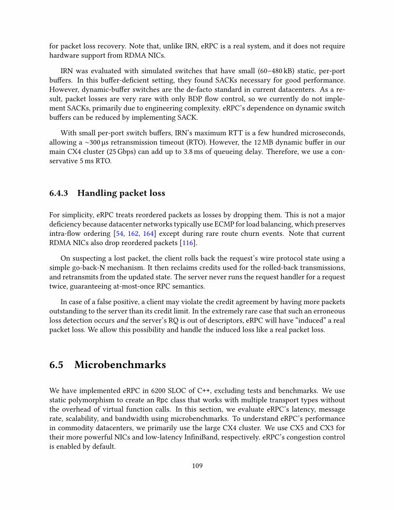
for packet loss recovery. Note that, unlike IRN, eRPC is a real system, and it does not requirehardware support from RDMA NICs.
IRN was evaluated with simulated switches that have small (60–480 kB) static, per-portbu�ers. In this bu�er-de�cient setting, they found SACKs necessary for good performance.However, dynamic-bu�er switches are the de-facto standard in current datacenters. As a re-sult, packet losses are very rare with only BDP �ow control, so we currently do not imple-ment SACKs, primarily due to engineering complexity. eRPC’s dependence on dynamic switchbu�ers can be reduced by implementing SACK.
With small per-port switch bu�ers, IRN’s maximum RTT is a few hundred microseconds,allowing a ∼300 µs retransmission timeout (RTO). However, the 12 MB dynamic bu�er in ourmain CX4 cluster (25 Gbps) can add up to 3.8 ms of queueing delay. Therefore, we use a con-servative 5 ms RTO.
6.4.3 Handling packet loss
For simplicity, eRPC treats reordered packets as losses by dropping them. This is not a majorde�ciency because datacenter networks typically use ECMP for load balancing, which preservesintra-�ow ordering [54, 162, 164] except during rare route churn events. Note that currentRDMA NICs also drop reordered packets [116].
On suspecting a lost packet, the client rolls back the request’s wire protocol state using asimple go-back-N mechanism. It then reclaims credits used for the rolled-back transmissions,and retransmits from the updated state. The server never runs the request handler for a requesttwice, guaranteeing at-most-once RPC semantics.
In case of a false positive, a client may violate the credit agreement by having more packetsoutstanding to the server than its credit limit. In the extremely rare case that such an erroneousloss detection occurs and the server’s RQ is out of descriptors, eRPC will have “induced” a realpacket loss. We allow this possibility and handle the induced loss like a real packet loss.
6.5 Microbenchmarks
We have implemented eRPC in 6200 SLOC of C++, excluding tests and benchmarks. We usestatic polymorphism to create an Rpc class that works with multiple transport types withoutthe overhead of virtual function calls. In this section, we evaluate eRPC’s latency, messagerate, scalability, and bandwidth using microbenchmarks. To understand eRPC’s performancein commodity datacenters, we primarily use the large CX4 cluster. We use CX5 and CX3 fortheir more powerful NICs and low-latency In�niBand, respectively. eRPC’s congestion controlis enabled by default.
109
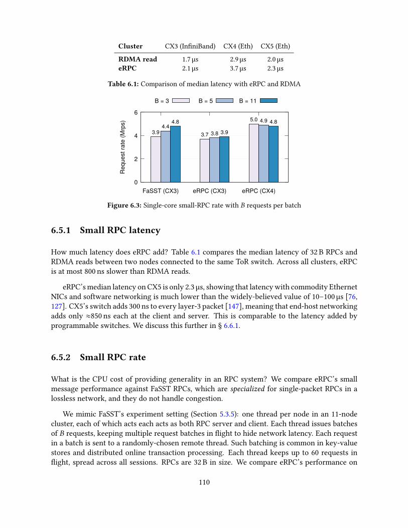
Cluster CX3 (In�niBand) CX4 (Eth) CX5 (Eth)
RDMA read 1.7 µs 2.9 µs 2.0 µseRPC 2.1 µs 3.7 µs 2.3 µs
Table 6.1: Comparison of median latency with eRPC and RDMA
0
2
4
6
FaSST (CX3) eRPC (CX3) eRPC (CX4)
Req
uest
rate
(Mrp
s)
B = 3 B = 5 B = 11
3.9 3.7
5.04.4
3.8
4.94.8
3.9
4.8
Figure 6.3: Single-core small-RPC rate with B requests per batch
6.5.1 Small RPC latency
How much latency does eRPC add? Table 6.1 compares the median latency of 32 B RPCs andRDMA reads between two nodes connected to the same ToR switch. Across all clusters, eRPCis at most 800 ns slower than RDMA reads.
eRPC’s median latency on CX5 is only 2.3 µs, showing that latency with commodity EthernetNICs and software networking is much lower than the widely-believed value of 10–100 µs [76,127]. CX5’s switch adds 300 ns to every layer-3 packet [147], meaning that end-host networkingadds only ≈850 ns each at the client and server. This is comparable to the latency added byprogrammable switches. We discuss this further in § 6.6.1.
6.5.2 Small RPC rate
What is the CPU cost of providing generality in an RPC system? We compare eRPC’s smallmessage performance against FaSST RPCs, which are specialized for single-packet RPCs in alossless network, and they do not handle congestion.
We mimic FaSST’s experiment setting (Section 5.3.5): one thread per node in an 11-nodecluster, each of which acts each acts as both RPC server and client. Each thread issues batchesof B requests, keeping multiple request batches in �ight to hide network latency. Each requestin a batch is sent to a randomly-chosen remote thread. Such batching is common in key-valuestores and distributed online transaction processing. Each thread keeps up to 60 requests in�ight, spread across all sessions. RPCs are 32 B in size. We compare eRPC’s performance on
110

Action RPC rate % loss
Baseline (with congestion control) 4.96 M/s –
Disable batched RTT timestamps (§6.4.2) 4.84 M/s 2.4%Disable Timely bypass (§6.4.2) 4.52 M/s 6.6%Disable rate limiter bypass (§6.4.2) 4.30 M/s 4.8%
Disable multi-packet RQ (§6.3.1) 4.06 M/s 5.6%Disable preallocated responses (§6.3.3) 3.55 M/s 12.6%Disable 0-copy request processing (§6.3.2.3) 3.05 M/s 14.0%
Table 6.2: Impact of disabling optimizations on small RPC rate (CX4)
CX3 (In�niBand) against FaSST’s reported numbers on the same cluster. We also present eRPC’sperformance on the CX4 Ethernet cluster. We omit CX5 since it has only 8 nodes.
Figure 6.3 shows that eRPC’s per-thread request issue rate is at most 18% lower than FaSSTacross all batch sizes, and only 5% lower for B = 3. This performance drop is acceptable sinceeRPC is a full-�edged RPC system, whereas FaSST is highly specialized. On CX4, each threadissues 5 million requests per second (Mrps) for B = 3; due to the experiment’s symmetry, itsimultaneously also handles incoming requests from remote threads at 5 Mrps. Therefore, eachthread processes 10 million RPCs per second.
Disabling congestion control increases eRPC’s request rate on CX4 (B = 3) from 4.96 Mrpsto 5.44 Mrps. This shows that the overhead of our optimized congestion control is only 9%.
Factor analysis. How important are eRPC’s common-case optimizations? Table 6.2 showsthe performance impact of disabling some of eRPC’s common-case optimizations on CX4; otheroptimizations such as our single-DMA msgbuf format and unsignaled transmissions cannot bedisabled easily. For our baseline, we use B = 3 and enable congestion control. Disabling allthree congestion control optimizations (§ 6.4.2.2) reduces throughput to 4.3 Mrps, increasing theoverhead of congestion control from 9% to 20%. Further disabling preallocated responses andzero-copy request processing reduces throughput to 3 Mrps, which is 40% lower than eRPC’speak throughput. We therefore conclude that optimizing for the common case is both necessaryand su�cient for high-performance RPCs.
6.5.3 Session scalability
We evaluate eRPC’s scalability on CX4 by increasing the number of nodes in the previous exper-iment (B = 3) to 100. The �ve ToR switches in CX4 were assigned between 14 and 27 nodes eachby CloudLab. Next, we increase the number of threads per node: WithT threads per node, thereare 100T threads in the cluster; each thread creates a client-mode session to 100T − 1 threads.Therefore, each node hostsT ∗ (100T − 1) client-mode sessions, and an equal number of server-mode sessions. Since CX4 nodes have 10 cores, each node handles up to 19980 sessions. Thisis a challenging tra�c pattern that resembles distributed online transaction processing (OLTP)
111

1
10
100
1000
0 2 4 6 8 10La
tenc
y (m
icro
seco
nds)
Threads per node
99.99% 99.9% 99% Median
Figure 6.4: Latency with increasing threads on 100 CX4 nodes
workloads, which operate on small data items (Section 2.2.4).
With 10 threads/node, each node achieves 12.3 Mrps on average. At 12.3 Mrps, each nodesends and receives 24.6 million packets per second (packet size = 92 B), corresponding to 18.1 Gbps.This is close to the link’s achievable bandwidth (23 Gbps out of 25 Gbps), but is somewhatsmaller because of oversubscription. We observe retransmissions with more than two threadsper node, but the retransmission rate stays below 1700 packets per second per node.
Figure 6.4 shows the RPC latency statistics. The median latency with one thread per nodeis 12.7 µs. This is higher than the 3.7 µs for CX4 in Table 6.1 because most RPCs now go acrossmultiple switches, and each thread keeps 60 RPCs in �ight, which adds processing delay. Evenwith 10 threads per node, eRPC’s 99.99th percentile latency stays below 700 µs.
These results show that eRPC can achieve high message rate, bandwidth, and scalability, andlow latency in a large cluster with lossy Ethernet. Distributed OLTP has been a key applicationfor lossless RDMA fabrics; our results show that it can also perform well on lossy Ethernet.
6.5.4 Large RPC bandwidth
We evaluate eRPC’s bandwidth using one client thread that sends large messages to a remoteserver thread. The client sends R-byte requests and keeps one request outstanding; the serverreplies with a small 32 B response. We use up to 8 MB requests, which is the largest message sizesupported by eRPC. We use 32 credits per session. To understand how eRPC performs relativeto hardware limits, we compare against R-byte RDMA writes, measured using the perftestbenchmarking tool.
On the clusters listed in Table 2.2, eRPC saturates the network’s per-port bandwidth withone CPU core. To understand eRPC’s per-core performance limit, we connect two nodes in theCX5 cluster to a 100 Gbps switch via ConnectX-5 In�niBand NICs. (We use CX5 as a 40 GbEcluster in the rest of this thesis.) Figure 6.5 shows that eRPC achieves up to 75 Gbps with onecore. eRPC’s throughput is at least 70% of RDMA write throughput for 32 kB or larger requests.
112

0
20
40
60
80
100
0.5 2 8 32 128 512 2048 8192 0
20
40
60
80
100
Goo
dput
(Gbp
s)
Perc
enta
ge
Request size (KB)
eRPCRDMA write
Percentage of RDMA write
Figure 6.5: Throughput of large transfers over 100 Gbps In�niBand
Loss rate 10−7 10−6 10−5 10−4 10−3
Bandwidth (Gbps) 73 71 57 18 2.5
Table 6.3: eRPC’s 8 MB request throughput with packet loss
In the future, eRPC’s bandwidth can be improved by freeing-up CPU cycles. First, on-diememory copy accelerators can speed up copying data from RX ring bu�ers to request or re-sponse msgbufs [42, 45]. Commenting out the memory copies at the server increases eRPC’sbandwidth to 92 Gbps, showing that copying has substantial overhead. Second, cumulativecredit return and request-for-response (Section 6.4.1) can reduce packet processing overhead.
Table 6.3 shows the throughput with R = 8 MB, and varying, arti�cially-injected packetloss rates. With the current 5 ms RTO, eRPC is usable while the loss probability is up to .01%,beyond which throughput degrades rapidly. We believe that this is su�cient to handle packetcorruptions. RDMA NICs can handle a somewhat higher loss rate (.1%) [165], likely because ofsupport for negative acknowledgments, which eRPC currently lacks.
Incast degree Total bw 50% RTT 99% RTT
20 21.8 Gbps 39 µs 67 µs20 (no cc) 23.1 Gbps 202 µs 204 µs
50 18.4 Gbps 34 µs 174 µs50 (no cc) 23.0 Gbps 524 µs 524 µs
100 22.8 Gbps 349 µs 969 µs100 (no cc) 23.0 Gbps 1056 µs 1060 µs
Table 6.4: E�ectiveness of congestion control (cc) during incast
113
6.5.5 E�ectiveness of congestion control
We evaluate if our congestion control is successful at reducing switch queueing. We create anincast tra�c pattern by increasing the number of client nodes in the previous setup (R = 8 MB).The one server node acts as the incast victim. During an incast, queuing primarily happens atthe victim’s ToR switch. We use per-packet RTTs measured at the clients as a proxy for switchqueue length [115].
Table 6.4 shows the total bandwidth achieved by all �ows and per-packet RTT statistics onCX4, for 20, 50, and 100-way incasts (one �ow per client node). We use two con�gurations:�rst with eRPC’s optimized congestion control, and second with no congestion control. Dis-abling our common-case congestion control optimizations does not substantially a�ect the RTTstatistics, indicating that these optimizations do not reduce the quality of congestion control.
Congestion control successfully handles our target workloads of up to 50-way incasts, re-ducing median and 99th percentile queuing by over 5x and 3x, respectively. For 100-way in-casts, our implementation reduces median queueing by 3x, but fails to substantially reduce99th percentile queueing. This is in line with Zhu et al. [166, § 4.3]’s analysis, which shows thatTimely-like protocols work well with up to approximately 40 incast �ows.
The combined incast throughput with congestion control is within 20% of the achievable23 Gbps. We believe that this small gap can be further reduced with better tuning of Timely’smany parameters. Note that we can also support ECN-based congestion control in eRPC, whichmay be a better congestion indicator than RTT [166].
Incast with background tra�c. Next, we augment the setup above to mimic an experimentfrom Timely [115, Fig 22]: we create one additional thread at each node that is not the incast vic-tim. These threads exchange latency-sensitive RPCs (64 kB request and response), keeping oneRPC outstanding. During a 100-way incast, the 99th percentile latency of these RPCs is 274 µs.This is similar to Timely’s latency (≈200-300 µs) with a 40-way incast over a 20 GbE losslessRDMA fabric. Although the two results cannot be directly compared, this experiment showsthat the latency achievable with software-only networking in commodity, lossy datacenters iscomparable to lossless RDMA fabrics, even with challenging tra�c patterns.
6.6 Full-system evaluations
This section describes our experience with building real systems with eRPC, and the imple-mentation and evaluation of these systems. We show that eRPC brings the speed of moderndatacenter networks to unmodi�ed existing storage software: We build a state machine repli-cation system using an open-source implementation of Raft [121], and a networked orderedkey-value store using Masstree [105].
114

Measurement System Median 99%
Measured at client NetChain 9.7 µs N/AeRPC 5.5 µs 6.3 µs
Measured at leader ZabFPGA 3.0 µs 3.0 µseRPC 3.1 µs 3.4 µs
Table 6.5: Latency comparison for replicated PUTs
6.6.1 Raft over eRPC
We have implemented a highly-available replicated in-memory key-value store on top of eRPC.We avoid the complexity of implementing a state machine replication system from scratch (Sec-tion 2.2.3), we use an existing implementation of the Raft protocol [23]. (It had no distinct name,so we term it LibRaft.) We did not write LibRaft ourselves; we found it on GitHub and used itas-is. LibRaft is well-tested with fuzzing over a network simulator and 150+ unit tests. Itsonly requirement is that the user provide callbacks for sending and handling RPCs—which weimplement using eRPC. Porting to eRPC required no changes to LibRaft’s code.
We compare against recent consistent replication systems that are built from scratch fortwo specialized hardware types. First, NetChain [76] implements chain replication over pro-grammable switches. Other replication protocols such as conventional primary-backup andRaft are too complex to implement over programmable switches [76]. Therefore, despite theprotocol-level di�erences between LibRaft-over-eRPC and NetChain, our comparison helpsunderstand the relative performance of end-to-end software-based designs and switch-baseddesigns for in-memory replication. Second, Consensus in a Box [72] (called ZabFPGA here),implements ZooKeeper’s atomic broadcast protocol [62] on FPGAs. eRPC also outperformsDARE [129], which implements SMR over RDMA; we omit the results for brevity.
Workloads. We mimic NetChain and ZabFPGA’s experiment setups for latency measure-ment: we use three-way replication, and use one client to issue PUT requests. The replicas’command logs and key-value store are stored in DRAM. NetChain and ZabFPGA use 16 B keys,and 16–64 B values; we use 16 B keys and 64 B values. The client chooses PUT keys uniformly atrandom from one million keys. While NetChain and ZabFPGA also implement their key-valuestores from scratch, we reuse existing code from MICA [97]. We compare eRPC’s performanceon CX5 against their published numbers because we do not have the hardware to run NetChainor ZabFPGA. Table 6.5 compares the latencies of the three systems.
6.6.1.1 Comparison with NetChain
NetChain’s key assumption is that software networking adds 1–2 orders of magnitude morelatency than switches [76]. However, we have shown that eRPC adds 850 ns, which is onlyaround 2x higher than latency added by current programmable switches (400 ns [10]).
Raft’s latency over eRPC is 5.5 µs, which is substantially lower than NetChain’s 9.7 µs. This
115
result must be taken with a grain of salt: On the one hand, NetChain uses NICs that havehigher latency than CX5’s NICs. On the other hand, it has numerous limitations, including key-value size and capacity constraints, serial chain replication whose latency increases linearlywith the number of replicas, absence of congestion control, and reliance on a complex andexternal failure detector. The main takeaway is that microsecond-scale consistent replicationis achievable in commodity Ethernet datacenters with a general-purpose networking library.
6.6.1.2 Comparison with ZabFPGA
Although ZabFPGA’s SMR servers are FPGAs, the clients are commodity workstations thatcommunicate with the FPGAs over slow kernel-based TCP. For a challenging comparison,we compare against ZabFPGA’s commit latency measured at the leader, which involves onlyFPGAs. In addition, we consider its “direct connect” mode, where FPGAs communicate overpoint-to-point links (i.e., without a switch) via a custom protocol. Even so, eRPC’s medianleader commit latency is only 3% worse.
An advantage of specialized, dedicated hardware is low jitter, highlighted by ZabFPGA’snegligible leader latency variance. This advantage does not carry over directly to end-to-endlatency [72] because storage systems built with specialized hardware are eventually accessedby clients running on commodity workstations.
6.6.2 Masstree over eRPC
Masstree [105] is an ordered in-memory key-value store. We use it to implement a single-nodedatabase index that supports low-latency point queries in the presence of less performance-critical longer-running scans. This requires running scans in worker threads. We use CX3 forthis experiment to show that eRPC works well on In�niBand.
We populate a Masstree server on CX3 with one million random 8 B keys mapped to 8 Bvalues. The server has 16 Hyper-Threads, which we divide between 14 dispatch threads and 2worker threads. We run 64 client threads spread over 8 client nodes to generate the workload.The workload consists of 99% GET(key) requests that fetch a key-value item, and 1% SCAN(key)requests that sum up the values of 128 keys succeeding the query key. Keys are chosen uni-formly at random from the inserted keys. Two outstanding requests per client was su�cient tosaturate our server.
We achieve 14.3 million GETs/s on CX3, with 12 µs 99th percentile GET latency. If the serveris con�gured to run only dispatch threads, the 99th percentile GET latency rises to 26 µs. eRPC’smedian GET latency under low load is 2.7 µs. This is around 10x faster than Cell’s single-nodeB-Tree that uses multiple RDMA reads [114]. Despite Cell’s larger key/value sizes (64 B/256 B),the latency di�erences are mostly from RTTs: At 40 Gbps, an additional 248 B takes only 50 nsmore time to transmit.
116
6.7 Conclusion
eRPC is the �rst general-purpose communication library that provides near-network-speedperformance in modern lossy Ethernet datacenters. eRPC’s speed comes from the observationthat switch bu�er capacity far exceeds datacenter BDP, prioritizing common-case performance,carefully combining a wide range of old and new optimizations. eRPC delivers performancethat was until now believed possible only with lossless RDMA fabrics or specialized networkhardware. It provides a �exible, end-to-end alternative to putting more functions in networkhardware, and specialized system designs that depend on these functions. It allows unmodi-�ed applications to perform close to the hardware limits. Our ported versions of LibRaft andMasstree are, to our knowledge, the fastest replicated key-value store and networked databaseindex in the academic literature, while operating end-to-end without additional network sup-port.
117

“How dull it is to pause, to make an end”
Alfred Lord Tennyson
Chapter 7
Lessons learned, limitations, and lookingforward
We conclude this thesis with discussion about the high-level lessons from our research, thelimitations of our systems’ evaluation, and avenues for future research.
7.1 Lessons learned
CPU architecture is well-matched to running high-performance distributed systems.At the time of writing, there is a tremendous push in the systems and networks research com-munity towards placing distributed system logic into network devices (i.e., “in-network com-puting”). Our work suggests that CPUs are, in fact, a good match for building distributed sys-tems, in terms of performance, scalability, �exibility, scalability, and simplicity. The general-purpose programmability of CPUs allows easy innovation, debugging, testing, deployment, andaddition of new features and technologies. These factors typically do not get su�cient attentionby the research community while evaluating the costs and bene�ts of in-network computingfor distributed systems.
Although this thesis does not explore power e�ciency, our systems deliver higher perfor-mance with equal or fewer hardware resources, indicating that they have higher performanceper watt, too. In addition, our prior work demonstrated that CPUs are competitive with FPGAsfor in-memory key-value storage [94], which is a workload with characteristics similar to thoseexplored in this thesis.
StrongerCPUbaselines are crucial for in-network computing research. Many in-networkcomputing projects demonstrate higher performance and CPU savings in comparison to slowsoftware baselines that do not represent the highest performance achievable by software-onlydesigns. Our work on eRPC provides a way forward for better comparisons: comparing againsta fast baseline allows zooming-in on fundamental di�erences between CPUs and in-networkdevices, such as their hardware architecture, and placement in the network. As an extreme
118

example, NetChain [76] compares a highly-optimized switch-based state machine replicationsystem against Apache ZooKeeper, which uses the kernel’s network stack. Our work suggeststhat much of the improvements observed in these projects can also be achieved by improvingthe software baseline with state-of-the-art, software-only techniques. For example, we showedin Chapter 6 that a state machine replication system running on a kernel-bypass communica-tion library outperforms NetChain.
Low-level optimizations are su�ciently critical that they can change the relative per-formance of high-level designs. We are used to thinking about low-level optimizations ascontributing a few percentage points to overall system performance. However, due to the com-plexity and feature-richness of modern hardware, the e�ect of low-level optimizations is oftenbig enough to change which high-level system design is faster or more scalable. These opti-mizations are often obscure and challenging to get right, which is why prior work sometimesmissed speedup opportunities. For example, in the context of their performance measurementsthat missed some low-level optimizations, the designers of Pilaf and FaRM-KV made the correctdecision to use multiple RDMA reads over one RPC; their RPCs were slow, but not fundamen-tally so.
Consider end-to-end designs early. Although eRPC builds on top of many recent researchresults, it was (in theory) possible to create eRPC six years ago when we started this work.For several years, we mistakenly—but for good reason—believed that one-sided RDMA and/orlossless networks were necessary for good performance. We and other researchers did notconsider end-to-end designs because we believed that such designs would not perform well,in part because we had not found all the required low-level optimizations. In the end, were-discovered an essential lesson from the end-to-end arguments paper: “Using performance tojustify placing functions in a low-level subsystemmust be done carefully. Sometimes, by examiningthe problem thoroughly, the same or better performance can be achieved at the high level.”
7.2 Limitations
Limited NIC model variety. At the time of writing, Mellanox is the only major vendor ofhigh-speed NICs with userspace device drivers. NICs from other vendors add several microsec-onds of latency, or require going through the OS kernel, or are not easily purchasable. As aconsequence, our experiments use only Mellanox NICs, although we have tested our �ndingson NICs released over the course of a decade (Table 2.2). The selection of fast NICs is likely toimprove soon, with new 100 GbE NICs from Intel and Broadcom on the horizon.
Evaluation in large datacenters. We conducted our research in an academic setting, wherewe had access to clusters with up to 200 hosts, but lacked access to large datacenters withthousands of hosts. In addition to large scale, networks in large datacenters also carry tra�cfrom other applications that use communication protocols di�erent from eRPC. Although wehave not tested eRPC at very large scale and with co-located tra�c, we believe that it will workwell in such settings. A key determinant of performance in large, co-located environments is
119

the congestion control protocol, and we deliberately chose to use an existing congestion controlprotocol (i.e., Timely) that has been deployed in hyperscale datacenters at Google. In addition,datacenters often con�ne communication-intensive workloads to pods [95]. Pods contain a fewhundred hosts and each pod runs one workload, which is a setting that we have shown eRPCperforms well in.
Co-locatedworkloads. To improve resource utilization, datacenter operators often co-locateworkloads on hosts. For example, a latency-sensitive in-memory key-value store applicationmay run alongside a low-priority data analytics application on the same host. During a periodin which the key-value store is idle, the host’s operating system may use all CPU cores to runanalytics. As a result, incoming RPC requests for a key-value item will su�er from the over-head of interrupts and process context switching. We designed eRPC for use in more exclusivesettings, where some cores or the entire machine is available to the application using eRPC.Recent work from Ka�es et al. [78] and Ousterhout et al. [123] shows promising results forachieving both high utilization and high performance in such co-located settings, which canapply to eRPC.
7.3 Future work
It is an especially exciting time for high-performance networking research: fast networks arenow commonplace in datacenters, and non-volatile memory has �nally broken the storage la-tency barrier. The software bloat and ine�ciency in current implementations of networkingsoftware can no longer hide behind slow networks and storage.
This thesis investigated how far existing hardware architectures can go towards achievingthe speed of the underlying network in these systems. We now understand the limits of CPUs,and are in a more informed position to investigate specialized hardware solutions. For example,eRPC shows that line rate on current 100 Gbps networks (with one core) is achievable withoutin-network support, but we likely cannot reach terabit-per-second speeds. What functionality,if any, should we put into networks to reach terabit network speeds in applications?
Our work opens several new avenues in datacenter networking that are ripe for investiga-tion, discussed next.
7.3.1 Protocol and API design for datacenter networks
One of eRPC’s biggest contributions was showing that we can support reliability and conges-tion control with low CPU overhead. It is therefore unclear why existing datacenter transportprotocols such as TCP require much higher CPU cycles per packet: One CPU core can handle 15million RPCs per second with eRPC, but only around 1.5 million packets per second with opti-mized userspace TCP implementations. Early pioneers of TCP have shown that TCP’s originaldatapath is simple and can be implemented with low overhead [28]. Is this still the case? If so, a
120
likely cause for low performance could be the POSIX send/recv API that handles only one con-nection per call. In contrast, eRPC’s API is explicitly designed to permit batched processing ofmultiple RPCs, on possibly di�erent connections. Such batching allows several optimizations,such as faster network I/O and prefetching memory locations. These results, together withthe increasing need for the underlying hardware to be parallel, suggest that a batching-centricredesign of operating system APIs may yield substantial bene�ts.
7.3.2 Towards a full-�edged networking library
Developers often desire features that are currently not provided by eRPC, such as encryption,and marshalling and unmarshalling of RPC arguments. These features are considered expen-sive, but we hypothesize that much of that perceived cost arises due to implementation ine�-ciencies and mismatches between hardware requirements and current API designs. For exam-ple, we believe that we can provide e�cient secure communication in an end-to-end fashionwithout in-network hardware devices such as FPGAs and on-NIC accelerators. Authenticatedencryption on modern CPUs is as fast as 0.64 cycles per byte [53], meaning that one CPU coremay send or receive encrypted data over the network at 40 Gbps on a modern 3.5 GHz pro-cessor. Another example of the usefulness of batched APIs is that, due to intra-core hardwareparallelism, these instructions are even more e�ective if multiple messages are available forsimultaneous processing.
The database community, in the heyday of in-memory and NoSQL databases, tried to un-derstand what makes a full-featured database slow [57]. They analyzed which componentsare slow fundamentally, and which due to implementation and design. A similar analysis fordatacenter networking is needed to establish a grounded basis for the development of futuresystems that successfully balance utility and e�ciency.
More generally, by better leveraging existing hardware, redesigning APIs with a groundedunderstanding of what limits e�ciency, and carefully choosing hardware specializations, wecan lay the groundwork for creating future systems that match the performance of ever-fasternetworks.
121

Bibliography
[1] Private communication with FaRM’s authors.[2] Private communication with Mellanox.[3] A Peek Inside Facebook’s Server Fleet Upgrade. https://www.nextplatform.com/
2017/03/13/peek-inside-facebooks-server-fleet-upgrade/.[4] Marcos K. Aguilera, Nadav Amit, Irina Calciu, Xavier Deguillard, Jayneel Gandhi, Pratap
Subrahmanyam, Lalith Suresh, Kiran Tati, Rajesh Venkatasubramanian, and Michael Wei.Remote memory in the age of fast networks. In Proc. 8th ACM Symposium on CloudComputing (SOCC), Santa Clara, CA, September 2017.
[5] Mohammad Al-Fares, Alex Loukissas, and Amin Vahdat. A scalable, commodity, datacenter network architecture. In Proc. ACM SIGCOMM, Seattle, WA, August 2008.
[6] Mohammad Alizadeh, Shuang Yang, Milad Sharif, Sachin Katti, Nick McKeown, BalajiPrabhakar, and Scott Shenker. pfabric: Minimal near-optimal datacenter transport. InProc. ACM SIGCOMM, Hong Kong, China, August 2013.
[7] Bob Alverson, Edwin Froese, Larry Kaplan, and Duncan Roweth. Cray XC series network.Cray Inc., White Paper WP-Aries01-1112, 2012.
[8] Amazon. Amazon Prime Day 2019 - Powered by AWS. https://aws.amazon.com/blogs/aws/amazon-prime-day-2019-powered-by-aws/.
[9] Berk Atikoglu, Yuehai Xu, Eitan Frachtenberg, Song Jiang, and Mike Paleczny. Workloadanalysis of a large-scale key-value store. In Proceedings of the SIGMETRICS’12, June 2012.
[10] Aurora 710 based on Barefoot To�no switching silicon. https://netbergtw.com/products/aurora-710/.
[11] AWS Nitro System. https://aws.amazon.com/ec2/nitro/.[12] Mahesh Balakrishnan, Dahlia Malkhi, Vijayan Prabhakaran, Ted Wobber, Michael Wei,
and John D. Davis. CORFU: a shared log design for �ash clusters. In Proc. 9th USENIXNSDI, San Jose, CA, April 2012.
[13] Barefoot Networks: Use Cases. https://www.barefootnetworks.com/use-cases/.[14] Brian W Barrett, Ron Brightwell, Scott Hemmert, Kevin Pedretti, Kyle Wheeler, Keith
Underwood, Rolf Riesen, Arthur B Maccabe, and Trammell Hudson. The Portals 4.0network programming interface November 14, 2012 draft.
[15] Adam Belay, George Prekas, Ana Klimovic, Samuel Grossman, Christos Kozyrakis, and
122

Edouard Bugnion. IX: A protected dataplane operating system for high throughput andlow latency. In 11th USENIX Symposium on Operating Systems Design and Implementation(OSDI 14), 2014.
[16] Carsten Binnig, Ugur Çetintemel, Andrew Crotty, Alex Galakatos, Tim Kraska, ErfanZamanian, and Stanley B. Zdonik. The end of slow networks: It’s time for a redesign.CoRR, abs/1504.01048, 2015. URL http://arxiv.org/abs/1504.01048.
[17] Carsten Binnig, Andrew Crotty, Alex Galakatos, Tim Kraska, and Erfan Zamanian. Theend of slow networks: It’s time for a redesign. In Proc. VLDB, New Delhi, India, August2016.
[18] Andrew D. Birrell and Bruce Jay Nelson. Implementing remote procedure calls. ACMTrans. Comput. Syst., 1984.
[19] Mark S. Birrittella, Mark Debbage, Ram Huggahalli, James Kunz, Tom Lovett, Todd Rim-mer, Keith D. Underwood, and Robert C. Zak. Intel Omni-path architecture: Enablingscalable, high performance fabrics. In Proceedings of the 2015 IEEE 23rd Annual Sympo-sium on High-Performance Interconnects, 2015.
[20] Pat Bosshart, Glen Gibb, Hun-Seok Kim, George Varghese, Nick McKeown, Martin Izzard,Fernando Mujica, and Mark Horowitz. Forwarding metamorphosis: Fast programmablematch-action processing in hardware for SDN. In Proc. ACM SIGCOMM, Hong Kong,China, August 2013.
[21] L. S. Brakmo, S. W. O’Malley, and L. L. Peterson. TCP vegas: New techniques for conges-tion detection and avoidance. In Proc. ACM SIGCOMM, London, England, August 1994.
[22] Broadcom Ethernet Network Adapters. https://www.broadcom.com/products/ethernet-connectivity/network-adapters.
[23] C implementation of the Raft Consensus protocol. https://github.com/willemt/raft.
[24] Brent Callaghan, Theresa Lingutla-Raj, Alex Chiu, Peter Staubach, and Omer Asad. NFSover RDMA. In Proceedings of the ACM SIGCOMMWorkshop on Network-I/O Convergence:Experience, Lessons, Implications, 2003.
[25] Fay Chang, Je�rey Dean, Sanjay Ghemawat, Wilson C. Hsieh, Deborah A. Wallach, MikeBurrows, Tushar Chandra, Andrew Fikes, and Robert E. Gruber. Bigtable: A distributedstorage system for structured data. In Proc. 7th USENIX OSDI, Seattle, WA, November2006.
[26] Yanzhe Chen, Xingda Wei, Jiaxin Shi, Rong Chen, and Haibo Chen. Fast and generaldistributed transactions using RDMA and HTM. In Proc. 11th ACM European Conferenceon Computer Systems (EuroSys), April 2016.
[27] D. Clark. The Design Philosophy of the DARPA Internet Protocols. In Proc. ACM SIG-COMM, pages 109–114, Stanford, CA, August 1988.
[28] D. C. Clark, V. Jacobson, J. Romkey, and H. Salwen. An Analysis of TCP ProcessingOverhead. IEEE Communications Magazine, June 1989.
[29] Brian Cooper, Adam Silberstein, Erwin Tam, Raghu Ramakrishnan, and Russell Sears.
123

Benchmarking cloud serving systems with YCSB. In Proc. 1st ACM Symposium on CloudComputing (SOCC), Indianapolis, IN, June 2010.
[30] D. Crupnico�, M. Kagan, A. Shahar, N. Bloch, and H. Chapman. Dynamically-connected transport service, May 19 2011. URL https://www.google.com/patents/US20110116512. US Patent App. 12/621,523.
[31] Andy Currid. TCP o�oad to the rescue. Queue. doi: 10.1145/1005062.1005069. URLhttp://doi.acm.org/10.1145/1005062.1005069.
[32] Je�rey Dean. Keynote address: Designs, lessons and advice from building large dis-tributed systems. In LADIS, 2009.
[33] Matt DeBergalis, Peter Corbett, Steve Kleiman, Arthur Lent, Dave Noveck, Tom Talpey,and Mark Wittle. The direct access �le system. In Proceedings of the 2Nd USENIX Con-ference on File and Storage Technologies, 2003.
[34] Guiseppe DeCandia, Deinz Hastorun, Madan Jampani, Gunavardhan Kakulapati,Avinash Lakshman, Alex Pilchin, Swami Sivasubramanian, Peter Vosshall, and WernerVogels. Dynamo: Amazon’s highly available key-value store. In Proc. 21st ACM Sympo-sium on Operating Systems Principles (SOSP), Stevenson, WA, October 2007.
[35] Saïd Derradji, Thibaut Palfer-Sollier, Jean-Pierre Panziera, Axel Poudes, andFrançois Wellenreiter Atos. The BXI interconnect architecture. In Proceedings ofthe 2015 IEEE 23rd Annual Symposium on High-Performance Interconnects, 2015.
[36] Distributed Asynchronous Object Storage Stack. https://github.com/daos-stack.[37] DPDK. Data Plane Development Kit (DPDK). http://dpdk.org/, 2017.[38] Aleksandar Dragojević, Dushyanth Narayanan, Orion Hodson, and Miguel Castro. FaRM:
Fast remote memory. In Proc. 11th USENIX NSDI, Seattle, WA, April 2014.[39] Aleksandar Dragojević, Dushyanth Narayanan, Edmund B. Nightingale, Matthew Ren-
zelmann, Alex Shamis, Anirudh Badam, and Miguel Castro. No compromises: Distributedtransactions with consistency, availability, and performance. In Proc. 25th ACM Sympo-sium on Operating Systems Principles (SOSP), Monterey, CA, October 2015.
[40] Aleksandar Dragojevic, Dushyanth Narayanan, and Miguel Castro. RDMA reads: To useor not to use? IEEE Data Eng. Bull., 2017.
[41] Dave Dunning, Greg Regnier, Gary McAlpine, Don Cameron, Bill Shubert, Frank Berry,Anne Marie Merritt, Ed Gronke, and Chris Dodd. The virtual interface architecture. IEEEMicro, pages 66–76, 1998.
[42] Michael Dalton et al. Andromeda: Performance, isolation, and velocity at scale in cloudnetwork virtualization. In Proc. 15th USENIX NSDI, Renton, WA, April 2018.
[43] Facebook Open Switching System FBOSS and Wedge in theopen. https://code.facebook.com/posts/843620439027582/facebook-open-switching-system-fboss-and-wedge-in-the-open/.
[44] Bin Fan, David G. Andersen, and Michael Kaminsky. MemC3: Compact and concur-rent memcache with dumber caching and smarter hashing. In Proc. 10th USENIX NSDI,
124
Lombard, IL, April 2013.[45] Fast memcpy with SPDK and Intel I/OAT DMA Engine. https://software.intel.com/
en-us/articles/fast-memcpy-using-spdk-and-ioat-dma-engine.[46] Wu-chun Feng, Pavan Balaji, Chris Baron, Laxmi N Bhuyan, and Dhabaleswar K Panda.
Performance characterization of a 10-gigabit Ethernet TOE. In 13th Symposium on HighPerformance Interconnects (HOTI’05). IEEE, 2005.
[47] Daniel Firestone et al. Azure accelerated networking: SmartNICs in the public cloud. InProc. 15th USENIX NSDI, Renton, WA, April 2018.
[48] Mario Flajslik and Mendel Rosenblum. Network interface design for low latency request-response protocols. In Proc. USENIXAnnual Technical Conference, San Jose, CA, June 2013.
[49] S. Floyd. TCP and Explicit Congestion Noti�cation. ACM Computer CommunicationsReview, 24(5), October 1994.
[50] Sebastian Gallenmüller, Paul Emmerich, Florian Wohlfart, Daniel Raumer, and GeorgCarle. Comparison of frameworks for high-performance packet io. In ANCS, 2015.
[51] Garth Gibson, Gary Grider, Andree Jacobson, and Wyatt Lloyd. PRObE: A Thousand-Node Experimental Cluster for Computer Systems Research.
[52] Juncheng Gu, Youngmoon Lee, Yiwen Zhang, Mosharaf Chowdhury, and Kang G. Shin.E�cient memory disaggregation with In�niswap. In Proc. 14th USENIX NSDI, Boston,MA, March 2017.
[53] Shay Gueron, Adam Langley, and Yehuda Lindell. Aes-gcm-siv: Speci�cation and analy-sis. 2017.
[54] Chuanxiong Guo, Lihua Yuan, Dong Xiang, Yingnong Dang, Ray Huang, David A. Maltz,Zhaoyi Liu, Vin Wang, Bin Pang, Hua Chen, Zhi-Wei Lin, and Varugis Kurien. Pingmesh:A large-scale system for data center network latency measurement and analysis. In Proc.ACM SIGCOMM, London, UK, August 2015.
[55] Chuanxiong Guo, Haitao Wu, Zhong Deng, Gaurav Soni, Jianxi Ye, Jitu Padhye, andMarina Lipshteyn. RDMA over commodity Ethernet at scale. In Proc. ACM SIGCOMM,Florianopolis, Brazil, August 2016.
[56] Sangjin Han, Keon Jang, KyoungSoo Park, and Sue Moon. PacketShader: a GPU-accelerated software router. In Proc. ACM SIGCOMM, New Delhi, India, August 2010.
[57] Stavros Harizopoulos, Daniel J. Abadi, Samuel Madden, and Michael Stonebraker. OLTPthrough the looking glass, and what we found there. In Proc. ACM SIGMOD, Vancouver,BC, Canada, June 2008.
[58] Simon Hauger, Thomas Wild, Arthur Mutter, Andreas Kirstaedter, Kimon Karras, RainerOhlendorf, Frank Feller, and Joachim Scharf. Packet processing at 100 Gbps and beyond- challenges and perspectives. In Photonic Networks, 2009 ITG Symposium on, 2009.
[59] Chris Hawblitzel, Jon Howell, Manos Kapritsos, Jacob R. Lorch, Bryan Parno, Michael L.Roberts, Srinath Setty, and Brian Zill. IronFleet: Proving practical distributed systemscorrect. In Proc. 25th ACM Symposium on Operating Systems Principles (SOSP), Monterey,
125
CA, October 2015.[60] Maurice Herlihy, Nir Shavit, and Moran Tzafrir. Hopscotch hashing. In Proceedings of
the 22Nd International Symposium on Distributed Computing, 2008.[61] Jian Huang, Xiangyong Ouyang, Jithin Jose, Md. Wasi ur Rahman, Hao Wang, Miao Luo,
Hari Subramoni, Chet Murthy, and Dhabaleswar K. Panda. High-Performance Design ofHBase with RDMA over In�niBand. In IPDPS, 2012.
[62] Patrick Hunt, Mahadev Konar, Flavio P. Junqueira, and Benjamin Reed. ZooKeeper: wait-free coordination for internet-scale systems. In Proc. USENIX Annual Technical Confer-ence, Boston, MA, June 2010.
[63] IEEE 802.1Qbb – Priority-based Flow Control. https://1.ieee802.org/dcb/802-1qbb/.
[64] In�niBand Architecture Speci�cation Volume 1. https://cw.infinibandta.org/document/dl/7859.
[65] Intel 82599. Intel 82599 10 Gigabit Ethernet Controller: Datasheet.http://www.intel.com/content/www/us/en/ethernet-controllers/82599-10-gbe-controller-datasheet.html, 2013.
[66] Intel Atom Processor C2000 Product Family for Microserver. http://www.intel.in/content/dam/www/public/us/en/documents/datasheets/atom-c2000-microserver-datasheet.pdf.
[67] Intel Optane DC Persistent Memory. https://www.intel.com/content/www/us/en/architecture-and-technology/optane-dc-persistent-memory.html.
[68] Intel Xeon Phi Processor Knights Landing Architectural Overview. https://www.nersc.gov/assets/Uploads/KNL-ISC-2015-Workshop-Keynote.pdf.
[69] Intel Xeon Processor D-1500 Product Family. http://www.intel.in/content/dam/www/public/us/en/documents/product-briefs/xeon-processor-d-brief.pdf.
[70] Intel Xeon Processor E5-1600/2400/2600/4600 (E5-Product Family) Product Families.http://www.intel.com/content/dam/www/public/us/en/documents/datasheets/xeon-e5-1600-2600-vol-2-datasheet.pdf.
[71] Intel Xeon Processor E5-1600/2400/2600/4600 v3 Product Families. http://www.intel.com/content/dam/www/public/us/en/documents/datasheets/xeon-e5-v3-datasheet-vol-2.pdf.
[72] Zsolt István, David Sidler, Gustavo Alonso, and Marko Vukolic. Consensus in a box:Inexpensive coordination in hardware. In Proc. 13th USENIX NSDI, Santa Clara, CA, May2016.
[73] Zsolt István, David Sidler, and Gustavo Alonso. Caribou: Intelligent distributed storage.August 2017.
[74] EunYoung Jeong, Shinae Woo, Muhammad Jamshed, Haewon Jeong, Sunghwan Ihm,Dongsu Han, and KyoungSoo Park. mTCP: A highly scalable user-level TCP stack formulticore systems. In Proc. 11th USENIX NSDI, Seattle, WA, April 2014.
126
https://www.intel.com/content/www/us/en/architecture-and-technology/optane-dc-persistent-memory.html
https://www.intel.com/content/www/us/en/architecture-and-technology/optane-dc-persistent-memory.html
http://www.intel.in/content/dam/www/public/us/en/documents/product-briefs/xeon-processor-d-brief.pdf
[75] Jim Warner’s switch bu�er page. https://people.ucsc.edu/~warner/buffer.html.[76] Xin Jin, Xiaozhou Li, Haoyu Zhang, Nate Foster, Jeongkeun Lee, Robert Soulé,
Changhoon Kim, and Ion Stoica. NetChain: Scale-free sub-RTT coordination. In Proc.15th USENIX NSDI, Renton, WA, April 2018.
[77] Jithin Jose, Hari Subramoni, Krishna Kandalla, Md. Wasi-ur Rahman, Hao Wang, SundeepNarravula, and Dhabaleswar K. Panda. Scalable memcached design for in�niband clustersusing hybrid transports. In Proc. CCGRID, 2012.
[78] Kostis Ka�es, Timothy Chong, Jack Tigar Humphries, Adam Belay, David Mazières, andChristos Kozyrakis. Shinjuku: Preemptive scheduling for microsecond-scale tail latency.In Proc. 16th USENIX NSDI, Boston, MA, February 2019.
[79] Anuj Kalia, Michael Kaminsky, and David G. Andersen. Using RDMA e�ciently for key-value services. In Proc. ACM SIGCOMM, Chicago, IL, August 2014.
[80] Anuj Kalia, Dong Zhou, Michael Kaminsky, and David G. Andersen. Raising the bar forusing GPUs in software packet processing. In Proc. 12th USENIX NSDI, Oakland, CA, May2015.
[81] Anuj Kalia, Michael Kaminsky, and David G. Andersen. FaSST: Fast, scalable and simpledistributed transactions with two-sided RDMA datagram RPCs. In Proc. 12th USENIXOSDI, Savannah, GA, November 2016.
[82] David Karger, Eric Lehman, Tom Leighton, Rina Panigrahy, Matthew Levine, and DanielLewin. Consistent hashing and random trees: distributed caching protocols for relievinghot spots on the world wide web. In STOC ’97: Proceedings of the twenty-ninth annualACM symposium on Theory of computing, pages 654–663, New York, NY, USA, 1997. ACM.
[83] Daehyeok Kim, Amirsaman Memaripour, Anirudh Badam, Yibo Zhu, Hongqiang HarryLiu, Jitu Padhye, Shachar Raindel, Steven Swanson, Vyas Sekar, and Srinivasan Seshan.HyperLoop: Group-based NIC-o�oading to accelerate replicated transactions in multi-tenant storage systems. In Proc. ACM SIGCOMM, Budapest, Hungary, August 2018.
[84] M. J. Koop, J. K. Sridhar, and D. K. Panda. Scalable MPI design over In�niBand using eX-tended Reliable Connection. In 2008 IEEE International Conference on Cluster Computing,2008.
[85] Leslie Lamport. Paxos made simple. ACM SIGACT News, 32(4), December 2001.[86] Leslie Lamport, Dahlia Malkhi, and Lidong Zhou. Vertical Paxos and primary-backup
replication. Technical report, Microsoft Research, 2009.[87] Steen Larsen and Ben Lee. Platform io dma transaction acceleration. In CACHES. ACM,
2011.[88] Changhyun Lee, Chunjong Park, Keon Jang, Sue Moon, and Dongsu Han. Accurate
latency-based congestion feedback for datacenters. In Proc. USENIX Annual TechnicalConference, Santa Clara, CA, June 2015.
[89] Viktor Leis, Alfons Kemper, and Thomas Neumann. The adaptive radix tree: Artful index-ing for main-memory databases. In Proceedings of the 2013 IEEE International Conferenceon Data Engineering (ICDE 2013), 2013.
127
[90] Bojie Li, Zhenyuan Ruan, Wencong Xiao, Yuanwei Lu, Yongqiang Xiong, Andrew Put-nam, Enhong Chen, and Lintao Zhang. KV-Direct: High-performance in-memory key-value store with programmable NIC. In Proc. 26th ACM Symposium on Operating SystemsPrinciples (SOSP), Shanghai, China, October 2017.
[91] Bojie Li, Tianyi Cui, Yibo Wang, Wei Bai, and Lintao Zhang. SocksDirect: Datacentersockets can be fast and compatible. In Proc. ACM SIGCOMM, Beijing, China, August2019.
[92] Jialin Li, Ellis Michael, Naveen Kr. Sharma, Adriana Szekeres, and Dan R. K. Ports. Justsay no to Paxos overhead: Replacing consensus with network ordering. In Proc. 12thUSENIX OSDI, Savannah, GA, November 2016.
[93] Jialin Li, Ellis Michael, and Dan R. K. Ports. Eris: Coordination-free consistent transac-tions using in-network concurrency control. In Proc. 26th ACM Symposium on OperatingSystems Principles (SOSP), Shanghai, China, October 2017.
[94] Sheng Li, Hyeontaek Lim, Victor W. Lee, Jung Ho Ahn, Anuj Kalia, Michael Kaminsky,David G. Andersen, O. Seongil, Sukhan Lee, and Pradeep Dubey. Architecting to achievea billion requests per second throughput on a single key-value store server platform. InISCA, 2015.
[95] Yuliang Li, Rui Miao, Hongqiang Harry Liu, Yan Zhuang, Fei Feng, Lingbo Tang, ZhengCao, Ming Zhang, Frank Kelly, Mohammad Alizadeh, and Minlan Yu. HPCC: High pre-cision congestion control. In Proc. ACM SIGCOMM, Beijing, China, August 2019.
[96] Hyeontaek Lim, Bin Fan, David G. Andersen, and Michael Kaminsky. SILT: A memory-e�cient, high-performance key-value store. In Proc. 23rd ACM Symposium on OperatingSystems Principles (SOSP), Cascais, Portugal, October 2011.
[97] Hyeontaek Lim, Dongsu Han, David G. Andersen, and Michael Kaminsky. MICA: Aholistic approach to fast in-memory key-value storage. In Proc. 11th USENIXNSDI, Seattle,WA, April 2014.
[98] Moritz Lipp, Michael Schwarz, Daniel Gruss, Thomas Prescher, Werner Haas, AndersFogh, Jann Horn, Stefan Mangard, Paul Kocher, Daniel Genkin, Yuval Yarom, and MikeHamburg. Meltdown: Reading kernel memory from user space. In 27th USENIX SecuritySymposium (USENIX Security 18), 2018.
[99] Feilong Liu, Lingyan Yin, and Spyros Blanas. Design and evaluation of an RDMA-awaredata shu�ing operator for parallel database systems. In Proc. 12th ACM European Con-ference on Computer Systems (EuroSys), April 2017.
[100] Jiuxing Liu, Jiesheng Wu, and Dhabaleswar K Panda. High performance RDMA-basedMPI implementation over In�niBand. International Journal of Parallel Programming, 2004.
[101] Jiuxing Liu, Jiesheng Wu, and Dhabaleswar K Panda. High performance RDMA-basedMPI implementation over In�niBand. International Journal of Parallel Programming, 2004.
[102] Ming Liu, Tianyi Cui, Henry Schuh, Arvind Krishnamurthy, and Simon Peter. O�oadingdistributed applications onto SmartNICs using iPipe. In Proc. ACM SIGCOMM, Beijing,China, August 2019.
128
[103] Xiaoyi Lu, Nusrat S. Islam, Md. Wasi ur Rahman, Jithin Jose, Hari Subramoni, Hao Wang,and Dhabaleswar K. Panda. High-performance design of hadoop RPC with RDMA overIn�niBand. In ICPP, 2013.
[104] Youyou Lu, Jiwu Shu, Youmin Chen, and Tao Li. Octopus: an RDMA-enabled distributedpersistent memory �le system. In 2017 USENIX Annual Technical Conference (USENIXATC 17), 2017.
[105] Yandong Mao, Eddie Kohler, and Robert Tappan Morris. Cache craftiness for fast mul-ticore key-value storage. In Proc. 7th ACM European Conference on Computer Systems(EuroSys), Bern, Switzerland, April 2012.
[106] Marvell LiquidIO 2 Smart NICs. https://www.marvell.com/ethernet-adapters-and-controllers/liquidio-smart-nics/.
[107] Mellanox BlueField Multicore System on a Chip. http://www.mellanox.com/products/bluefield-overview/.
[108] Mellanox ConnectX-4 Product Brief. http://www.mellanox.com/related-docs/prod_adapter_cards/PB_ConnectX-4_VPI_Card.pdf.
[109] Mellanox Innova-2 Flex Open Programmable SmartNIC. http://www.mellanox.com/related-docs/prod_adapter_cards/PB_Innova-2_Flex.pdf.
[110] Mellanox MLNX-OS User Manual for Ethernet. http://www.mellanox.com/related-docs/prod_management_software/MLNX-OS_ETH_v3_6_3508_UM.pdf.
[111] Mellanox OFED for Linux Release Notes. http://www.mellanox.com/related-docs/prod_software/Mellanox_OFED_Linux_Release_Notes_3_2-1_0_1_1.pdf.
[112] Memcached. Memcached: A distributed memory object caching system. http://memcached.org/, 2011.
[113] Christopher Mitchell, Yifeng Geng, and Jinyang Li. Using one-sided RDMA reads to builda fast, CPU-e�cient key-value store. In Proc. USENIX Annual Technical Conference, SanJose, CA, June 2013.
[114] Christopher Mitchell, Kate Montgomery, Lamont Nelson, Siddhartha Sen, and JinyangLi. Balancing CPU and network in the Cell distributed B-Tree store. In Proc. USENIXAnnual Technical Conference, Denver, CO, June 2016.
[115] Radhika Mittal, Terry Lam, Nandita Dukkipati, Emily Blem, Hassan Wassel, MoniaGhobadi, Amin Vahdat, Yaogong Wang, David Wetherall, and David Zats. TIMELY: RTT-based congestion control for the datacenter. In Proc. ACM SIGCOMM, London, UK, August2015.
[116] Radhika Mittal, Alexander Shpiner, Aurojit Panda, Eitan Zahavi, Arvind Krishnamurthy,Sylvia Ratnasamy, and Scott Shenker. Revisiting network support for RDMA. In Proc.ACM SIGCOMM, Budapest, Hungary, August 2018.
[117] Jacob Nelson, Brandon Holt, Brandon Myers, Preston Briggs, Luis Ceze, Simon Kahan,and Mark Oskin. Latency-tolerant software distributed shared memory. In Proc. USENIXAnnual Technical Conference, Santa Clara, CA, June 2015.
129
http://www.mellanox.com/related-docs/prod_software/Mellanox_OFED_Linux_Release_Notes_3_2-1_0_1_1.pdf
[118] Netronome Agilio SmartNICs. https://www.netronome.com/products/smartnic/overview/.
[119] Rajesh Nishtala, Hans Fugal, Steven Grimm, Marc Kwiatkowski, Herman Lee, Harry C.Li, Ryan McElroy, Mike Paleczny, Daniel Peek, Paul Saab, David Sta�ord, Tony Tung, andVenkateshwaran Venkataramani. Scaling Memcache at Facebook. In Proc. 10th USENIXNSDI, Lombard, IL, April 2013.
[120] Oak Ridge Leadership Computing Facility - Summit. https://www.olcf.ornl.gov/summit/.
[121] Diego Ongaro and John Ousterhout. In search of an understandable consensus algorithm.In Proc. USENIX Annual Technical Conference, Philadelphia, PA, June 2014.
[122] Diego Ongaro, Stephen M. Rumble, Ryan Stutsman, John Ousterhout, and Mendel Rosen-blum. Fast crash recovery in RAMCloud. In Proc. 23rd ACM Symposium on OperatingSystems Principles (SOSP), Cascais, Portugal, October 2011.
[123] Amy Ousterhout, Joshua Fried, Jonathan Behrens, Adam Belay, and Hari Balakrishnan.Shenango: Achieving high CPU e�ciency for latency-sensitive datacenter workloads. InProc. 16th USENIX NSDI, Boston, MA, February 2019.
[124] John Ousterhout, Arjun Gopalan, Ashish Gupta, Ankita Kejriwal, Collin Lee, BehnamMontazeri, Diego Ongaro, Seo Jin Park, Henry Qin, Mendel Rosenblum, Stephen Rumble,Ryan Stutsman, and Stephen Yang. The RAMCloud storage system. ACM TOCS, 2015.
[125] P4 Language Consortium. https://p4.org.[126] R. Pagh and F.F. Rodler. Cuckoo hashing. Journal of Algorithms, 51(2):122–144, May 2004.[127] Aurojit Panda, Sangjin Han, Keon Jang, Melvin Walls, Sylvia Ratnasamy, and Scott
Shenker. NetBricks: Taking the V out of NFV. In Proc. 12th USENIX OSDI, Savannah,GA, November 2016.
[128] PCI Express Base Speci�cation Revision 3.0. https://pcisig.com/specifications/.[129] Marius Poke and Torsten Hoe�er. DARE: High-performance state machine replication
on RDMA networks. In HPDC, 2015.[130] Dan R. K. Ports, Jialin Li, Vincent Liu, Naveen Kr. Sharma, and Arvind Krishnamurthy.
Designing distributed systems using approximate synchrony in data center networks. InProc. 12th USENIX NSDI, Oakland, CA, May 2015.
[131] Ken Ra�enetti, Abdelhalim Amer, Lena Oden, Charles Archer, Wesley Bland, Hajime Fu-jita, Yanfei Guo, Tomislav Janjusic, Dmitry Durnov, Michael Blocksome, Min Si, SangminSeo, Akhil Langer, Gengbin Zheng, Masamichi Takagi, Paul Co�man, Jithin Jose, Sayan-tan Sur, Alexander Sannikov, Sergey Oblomov, Michael Chuvelev, Masayuki Hatanaka,Xin Zhao, Paul Fischer, Thilina Rathnayake, Matt Otten, Misun Min, and Pavan Balaji.Why is mpi so slow?: Analyzing the fundamental limits in implementing MPI-3.1. InProceedings of the International Conference for High Performance Computing, Networking,Storage and Analysis, SC ’17, 2017.
[132] Shlomo Raikin, Liran Liss, Ariel Shachar, Noam Bloch, and Michael Kagan. Remote trans-actional memory, 2015. US Patent App. 20150269116.
130

[133] RDMAmojo - blog on RDMA technology and programming by Dotan Barak. http://www.rdmamojo.com/2013/01/12/ibv_modify_qp/.
[134] Redis. http://redis.io.[135] David P. Reed. Invited talk: End-to-end arguments: The Internet and beyond. In USENIX
Security, 2010.[136] Robert Ricci, Eric Eide, and The CloudLab Team. Introducing CloudLab: Scienti�c in-
frastructure for advancing cloud architectures and applications. USENIX ;login:, 2014.[137] Luigi Rizzo. netmap: a novel framework for fast packet I/O. In Proceedings of the 2012
USENIX conference on Annual Technical Conference, June 2012.[138] Arjun Roy, Hongyi Zeng, Jasmeet Bagga, George Porter, and Alex C. Snoeren. Inside
the social network’s (datacenter) network. In Proc. ACM SIGCOMM, London, UK, August2015.
[139] Ahmed Saeed, Nandita Dukkipati, Vytautas Valancius, Vinh The Lam, Carlo Contavalli,and Amin Vahdat. Carousel: Scalable tra�c shaping at end hosts. In Proc. ACM SIG-COMM, Los Angeles, CA, August 2017.
[140] J. Saltzer, D. Reed, and D. Clark. End-to-end Arguments in System Design. ACM Trans-actions on Computer Systems, 2:277–288, November 1984.
[141] Yee Jiun Song, Marcos K. Aguilera, Ramakrishna Kotla, and Dahlia Malkhi. RPC chains:E�cient client-server communication in geodistributed systems. In Proc. 6th USENIXNSDI, Boston, MA, April 2009.
[142] James W. Stamos and Flaviu Cristian. Coordinator log transaction execution protocol.Distrib. Parallel Databases, 1(4):383–408, October 1993. ISSN 0926-8782. doi: 10.1007/BF01264014. URL http://dx.doi.org/10.1007/BF01264014.
[143] Tyler Szepesi, Bernard Wong, Benjamin Cassell, , and Tim Brecht. Designing a low-latency cuckoo hash table for write-intensive workloads. In WSRC, 2014.
[144] Tyler Szepesi, Benjamin Cassell, Bernard Wong, Tim Brecht, and Xiaoyi Liu. Nessie:A decoupled, client-driven, key-value store using RDMA. Technical Report CS-2015-09, University of Waterloo, David R. Cheriton School of Computer Science, Waterloo,Canada, June 2015.
[145] Alexander Thomson, Thaddeus Diamond, Shu-Chun Weng, Kun Ren, Philip Shao, andDaniel J. Abadi. Calvin: Fast distributed transactions for partitioned database systems. InProceedings of the 2012 ACM SIGMOD International Conference on Management of Data,May 2012.
[146] To�no: World’s fastest P4-programmable Ethernet switch ASICs. https://barefootnetworks.com/products/brief-tofino/.
[147] Tolly report: Mellanox SX1016 and SX1036 10/40GbE switches.http://www.mellanox.com/related-docs/prod_eth_switches/Tolly212113MellanoxSwitchSXPerformance.pdf.
[148] TPC-C. TPC benchmark C. http://www.tpc.org/tpcc/, 2010.
131
[149] Stephen Tu, Wenting Zheng, Eddie Kohler, Barbara Liskov, and Samuel Madden. Speedytransactions in multicore in-memory databases. In Proc. 24th ACM Symposium on Oper-ating Systems Principles (SOSP), Farmington, PA, November 2013.
[150] Understanding Performance of PCI Express Systems. http://www.xilinx.com/support/documentation/white_papers/wp350.pdf.
[151] Robbert van Renesse and Fred B. Schneider. Chain replication for supporting highthroughput and availability. In Proc. 6th USENIX OSDI, San Francisco, CA, December2004.
[152] Yandong Wang, Xiaoqiao Meng, Li Zhang, and Jian Tan. C-hint: An e�ective and reliablecache management for RDMA-accelerated key-value stores. In Proc. 5th ACM Symposiumon Cloud Computing (SOCC), Seattle, WA, November 2014.
[153] Yandong Wang, Li Zhang, Jian Tan, Min Li, Yuqing Gao, Xavier Guerin, Xiaoqiao Meng,and Shicong Meng. Hydradb: A resilient RDMA-driven key-value middleware for in-memory cluster computing. In Proceedings of the International Conference for High Per-formance Computing, Networking, Storage and Analysis, 2015.
[154] Xingda Wei, Jiaxin Shi, Yanzhe Chen, Rong Chen, and Haibo Chen. Fast in-memory trans-action processing using RDMA and HTM. In Proc. 25th ACM Symposium on OperatingSystems Principles (SOSP), Monterey, CA, October 2015.
[155] Xingda Wei, Zhiyuan Dong, Rong Chen, and Haibo Chen. Deconstructing RDMA-enabled distributed transactions: Hybrid is better! In Proc. 13th USENIX OSDI, Carlsbad,CA, October 2018.
[156] Brian White, Jay Lepreau, Leigh Stoller, Robert Ricci, Shashi Guruprasad, Mac Newbold,Mike Hibler, Chad Barb, and Abhijeet Joglekar. An integrated experimental environmentfor distributed systems and networks. In Proc. 5th USENIX OSDI, pages 255–270, Boston,MA, December 2002.
[157] Jiesheng Wu, Pete Wycko�, and Dhabaleswar K. Panda. PVFS over In�niBand: Designand performance evaluation. In Ohio State University Tech Report, 2003.
[158] Reza Zamani and Ahmad Afsahi. Communication characteristics of message-passingscienti�c and engineering applications. In International Conference on Parallel and Dis-tributed Computing Systems, 2005.
[159] Erfan Zamanian, Carsten Binnig, Tim Harris, and Tim Kraska. The end of a myth: Dis-tributed transactions can scale. In Proc. VLDB, Munich, Germany, August 2017.
[160] Huanchen Zhang, David G. Andersen, Andrew Pavlo, Michael Kaminsky, Lin Ma, andRui Shen. Reducing the storage overhead of main-memory OLTP databases with hybridindexes. In Proc. ACM SIGMOD, San Francisco, USA, June 2016.
[161] Jiao Zhang, Fengyuan Ren, Xin Yue, Ran Shu, and Chuang Lin. Sharing bandwidth byallocating switch bu�er in data center networks. IEEE Journal on Selected Areas in Com-munications, 2014.
[162] Qiao Zhang, Vincent Liu, Hongyi Zeng, and Arvind Krishnamurthy. High-resolutionmeasurement of data center microbursts. In Proceedings of the 2017 Internet Measurement
132
Conference, IMC ’17, 2017.[163] Dong Zhou, Bin Fan, Hyeontaek Lim, David G. Andersen, and Michael Kaminsky. Scal-
able, High Performance Ethernet Forwarding with CuckooSwitch. In Proc. 9th Interna-tional Conference on emerging Networking EXperiments and Technologies (CoNEXT), De-cember 2013.
[164] Junlan Zhou, Malveeka Tewari, Min Zhu, Abdul Kabbani, Leon Poutievski, Arjun Singh,and Amin Vahdat. WCMP: Weighted cost multipathing for improved fairness in datacenters. In Proc. 9th ACM European Conference on Computer Systems (EuroSys), April2014.
[165] Yibo Zhu, Haggai Eran, Daniel Firestone, Chuanxiong Guo, Marina Lipshteyn, YehonatanLiron, Jitendra Padhye, Shachar Raindel, Mohamad Haj Yahia, and Ming Zhang. Conges-tion control for large-scale RDMA deployments. In Proc. ACM SIGCOMM, London, UK,August 2015.
[166] Yibo Zhu, Monia Ghobadi, Vishal Misra, and Jitendra Padhye. ECN or delay: Lessonslearnt from analysis of DCQCN and TIMELY. In Proc. CoNEXT, December 2016.
133