Efficient Heating at the Third Harmonic Electron … of ITC/ISHW2007 Efficient Heating at the Third...
4
Proceedings of ITC/ISHW2007 Efficient Heating at the Third Harmonic Electron Cyclotron Resonance in Large Helical Device Takashi SHIMOZUMA 1) , Shin KUBO 1) , Hiroe IGAMI 1) , Yasuo YOSHIMURA 1) , Takashi NOTAKE 2) , Nikolai B. MARUSHCHENKO 3) , Yurij. TURKIN 3) , Takashi MUTOH 1) and LHD Experimental Group 1) 1) National Institute for Fusion Science, 322-6 Oroshi-cho, Toki 509-5292 Japan 2) University of Fukui, Research Center for Development of Far-Infrared Region, 3-9-1 Bunkyo, Fukui 910-8507 Japan 3) Max-Plank-Institut f¨ ur Plasmaphysik, EURATOM-Association, Greifswald, Germany (Received / Accepted ) Efficient heating at the third harmonic electron cyclotron resonance was attained by injection of millimeter- wave power with 84 GHz frequency range at the magnetic field strength of 1 T in LHD. The plasma center clearly increased and the increment of the temperature reached 0.2 – 0.3 keV. Dependence of the power absorption rate on the antenna focal position was experimentally investigated, showing that the optimum position located in the slightly high-field side of the resonance layer. Ray-tracing calculation was performed in the realistic three- dimensional magnetic configuration. The results are compared with the experimental results. Keywords: electron cyclotron resonance heating, gyrotron, harmonic resonance, quasi optical antenna, ray tracing DOI: 10.1585/pfr.1.001 1. Introduction High harmonic heating of the electron cyclotron res- onance (ECR) is an attractive method to extend a heat- ing regime of plasma parameters by alleviating the density limitation due to some cutoffs of the EC wave propaga- tion. In the LHD launching geometry, the magnetic field strength is almost constant along the ray paths launched from upper- and lower-port antennas which cross near the magnetic axis. Under this condition, the ray can keep res- onant with the plasma over a considerable length. So good absorption is predicted over a wide density range even for the 3rd harmonic heating by the linear theory [1]. Experimentally the 3rd harmonic heating was tried in Heliotron DR and effective heating was observed [2]. In TCV tokamak, 3rd harmonic heating was carried out with the 2nd harmonic heating by using two different fre- quency gyrotrons such as 82.7 GHz for the 2nd harmonic and 118 GHz for the 3rd harmonic resonance. Hundred percent absorption was attained on existence of high en- ergy electrons produced by the 2nd harmonic resonance heating [3, 4]. After that, the sophisticated feedback con- trol of antenna focal position realized 100 % absorption by only 3rd harmonic resonance heating [5]. In W7- X, the 3rd harmonic heating is planned as a candidate of a normal heating scenario in the high density regime (0.6 − 2.0 × 10 20 m −3 ) by using 140 GHz, 10 MW ECH system [6]. Effective 3rd harmonic heating has been already achieved on the 2 T LHD plasma by injection of 168 GHz millimeter wave power from upper-port antennas. In the author’s e-mail: [email protected] experiments of the 3rd harmonic resonance heating, ob- vious heating of the bulk plasma (∆T e =0.2 keV) around the plasma center by 340 kW power injection was ob- served [7]. Because ECH power of 84 GHz range has been up- graded up to 1.3 MW recently, we have tried the 3rd harmonic extraordinary(X)-mode heating by injection of 84 GHz range power at the magnetic field strength of 1 T with the magnetic axis of 3.75 m. When the same fre- quency is used, a cutoff density for the 3rd harmonic X- mode heating at 1 T becomes 4/3 higher than that for 2nd harmonic X-mode heating at 1.5 T. It is about 6 × 10 19 m −3 . 2. Experimental setup and results The ECH system consists of 84 GHz range and 168 GHz gyrotrons, high voltage power supplies, long dis- tance transmission lines, and in-vessel quasi-optical an- tennas. It has been improved step by step. At the last campaign(2006) of LHD experiments five 84 GHz range and three 168 GHz gyrotrons are operated and ECH power could be injected from six antennas in the vertically elongated cross section (upper-port and lower-port anten- nas) and two antennas in the horizontally elongated cross section(outer-port antennas). Two kinds of antenna systems for ECH are installed in the LHD vacuum vessel. The vertical injection antenna system consists of four or two millimeter-wave focusing and steering mirrors. High power measurement of this sys- tem shows a good agreement with the designed beam-waist size of 15 mm in radial and 50 mm in toroidal direction for the upper-port antennas and of 30 mm for the lower-port
Transcript of Efficient Heating at the Third Harmonic Electron … of ITC/ISHW2007 Efficient Heating at the Third...
Proceedings of ITC/ISHW2007
Efficient Heating at the Third Harmonic Electron CyclotronResonance in Large Helical Device
Takashi SHIMOZUMA1), Shin KUBO1), Hiroe IGAMI1), Yasuo YOSHIMURA1), Takashi NOTAKE2),Nikolai B. MARUSHCHENKO3), Yurij. TURKIN3), Takashi MUTOH1) and LHD Experimental
Group1)
1)National Institute for Fusion Science, 322-6 Oroshi-cho, Toki 509-5292 Japan2)University of Fukui, Research Center for Development of Far-Infrared Region, 3-9-1 Bunkyo, Fukui 910-8507 Japan
3)Max-Plank-Institut fur Plasmaphysik, EURATOM-Association, Greifswald, Germany
(Received / Accepted )
Efficient heating at the third harmonic electron cyclotron resonance was attained by injection of millimeter-wave power with 84 GHz frequency range at the magnetic field strength of 1 T in LHD. The plasma center clearlyincreased and the increment of the temperature reached 0.2 – 0.3 keV. Dependence of the power absorption rateon the antenna focal position was experimentally investigated, showing that the optimum position located inthe slightly high-field side of the resonance layer. Ray-tracing calculation was performed in the realistic three-dimensional magnetic configuration. The results are compared with the experimental results.
Keywords: electron cyclotron resonance heating, gyrotron, harmonic resonance, quasi optical antenna, ray tracing
DOI: 10.1585/pfr.1.001
1. IntroductionHigh harmonic heating of the electron cyclotron res-
onance (ECR) is an attractive method to extend a heat-ing regime of plasma parameters by alleviating the densitylimitation due to some cutoffs of the EC wave propaga-tion. In the LHD launching geometry, the magnetic fieldstrength is almost constant along the ray paths launchedfrom upper- and lower-port antennas which cross near themagnetic axis. Under this condition, the ray can keep res-onant with the plasma over a considerable length. So goodabsorption is predicted over a wide density range even forthe 3rd harmonic heating by the linear theory [1].
Experimentally the 3rd harmonic heating was triedin Heliotron DR and effective heating was observed [2].In TCV tokamak, 3rd harmonic heating was carried outwith the 2nd harmonic heating by using two different fre-quency gyrotrons such as 82.7 GHz for the 2nd harmonicand 118 GHz for the 3rd harmonic resonance. Hundredpercent absorption was attained on existence of high en-ergy electrons produced by the 2nd harmonic resonanceheating [3, 4]. After that, the sophisticated feedback con-trol of antenna focal position realized 100 % absorptionby only 3rd harmonic resonance heating [5]. In W7-X, the 3rd harmonic heating is planned as a candidateof a normal heating scenario in the high density regime(0.6 − 2.0 × 10²⁰ m−3) by using 140 GHz, 10 MW ECHsystem [6].
Effective 3rd harmonic heating has been alreadyachieved on the 2 T LHD plasma by injection of 168 GHzmillimeter wave power from upper-port antennas. In the
author’s e-mail: [email protected]
experiments of the 3rd harmonic resonance heating, ob-vious heating of the bulk plasma (∆Te=0.2 keV) aroundthe plasma center by 340 kW power injection was ob-served [7].
Because ECH power of 84 GHz range has been up-graded up to 1.3 MW recently, we have tried the 3rdharmonic extraordinary(X)-mode heating by injection of84 GHz range power at the magnetic field strength of 1 Twith the magnetic axis of 3.75 m. When the same fre-quency is used, a cutoff density for the 3rd harmonic X-mode heating at 1 T becomes 4/3 higher than that for 2ndharmonic X-mode heating at 1.5 T. It is about 6×10¹⁹m−3.
2. Experimental setup and resultsThe ECH system consists of 84 GHz range and 168
GHz gyrotrons, high voltage power supplies, long dis-tance transmission lines, and in-vessel quasi-optical an-tennas. It has been improved step by step. At thelast campaign(2006) of LHD experiments five 84 GHzrange and three 168 GHz gyrotrons are operated and ECHpower could be injected from six antennas in the verticallyelongated cross section (upper-port and lower-port anten-nas) and two antennas in the horizontally elongated crosssection(outer-port antennas).
Two kinds of antenna systems for ECH are installedin the LHD vacuum vessel. The vertical injection antennasystem consists of four or two millimeter-wave focusingand steering mirrors. High power measurement of this sys-tem shows a good agreement with the designed beam-waistsize of 15 mm in radial and 50 mm in toroidal direction forthe upper-port antennas and of 30 mm for the lower-port
Proceedings of ITC/ISHW2007
antennas. The direction of the beam can be steered radi-ally and toroidally. The injected millimeter-wave beamsfrom these antennas consequently have a grazing incidenceangle to the cyclotron resonance and continues to interactalong a long ray-path. For horizontal injection, the antennasystem consists of 2 mirrors, one is fixed and another issteerable. Movable range covers the whole plasma crosssection for perpendicular injection and can change about±30 degrees toroidally. In this case, the injected beamsperpendicularly pass through the ECR layer with the short-est gradient length.
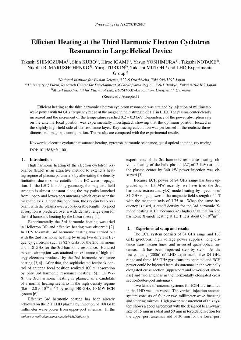
Fig. 1 Wave form of NBI power, ECH timing, stored energy Wp
and line-averaged density from top to bottom.
A magnetic configuration was chosen such that the 3rdharmonic electron cyclotron resonance located on the mag-netic axis for both in the vertically and horizontally elon-gated cross sections, because microwave beams from allantennas could access almost perpendicularly to the mag-netic field line of force. So the magnetic field strength of1 T on the magnetic axis placed on Rax = 3.75 m wasadopted.
In the experiments, target plasmas were produced andsustained by only NBI power. The electron temperatureof a target plasma was about 1 keV and the line-averageddensity was 0.6 × 10¹⁹m−3 at the center. ECH power(1.3 MW) was injected from t=1.4 sec and 1.5 sec stair-likely as shown in Fig. 1. The ECH pulse which has alonger pulse width corresponds to 84 GHz power from theouter-port antenna. The ECH pulse with a shorter pulsewidth is 82.7 GHz from top-antennas and 84 GHz frombottom-antennas. The absorption rate for the different wayof resonance can be discriminated independently and ef-fectively by the stair-like injection. Obvious increase ofthe stored energy was observed during both the first andsecond ECH pulses, while there was no change in the den-sity.
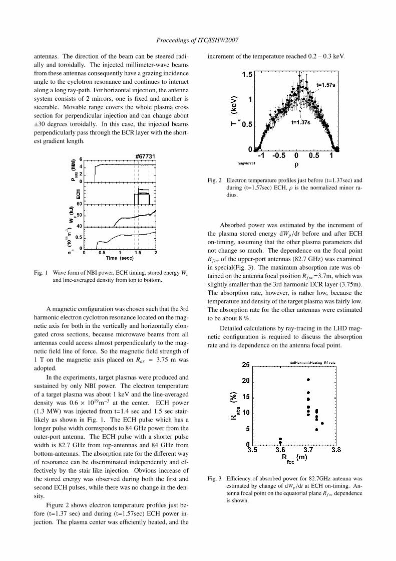
Figure 2 shows electron temperature profiles just be-fore (t=1.37 sec) and during (t=1.57sec) ECH power in-jection. The plasma center was efficiently heated, and the
increment of the temperature reached 0.2 – 0.3 keV.
Fig. 2 Electron temperature profiles just before (t=1.37sec) andduring (t=1.57sec) ECH. ρ is the normalized minor ra-dius.
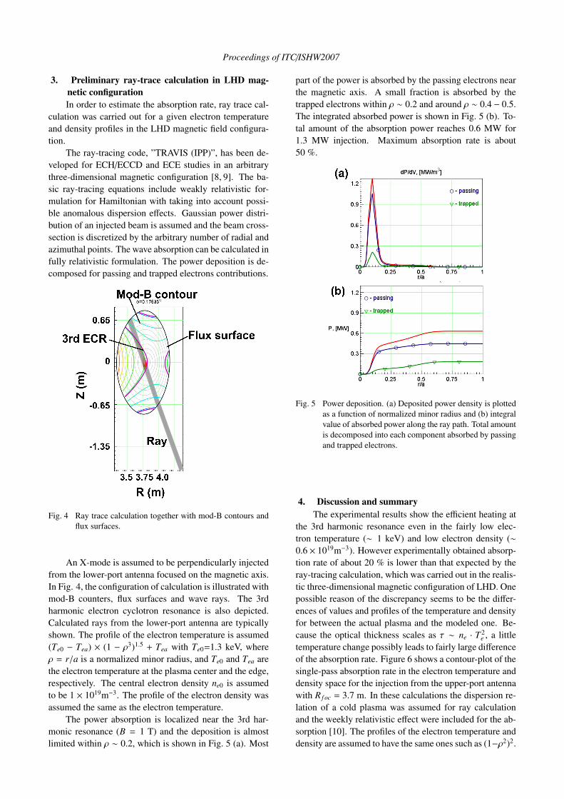
Absorbed power was estimated by the increment ofthe plasma stored energy dWp/dt before and after ECHon-timing, assuming that the other plasma parameters didnot change so much. The dependence on the focal pointR f oc of the upper-port antennas (82.7 GHz) was examinedin special(Fig. 3). The maximum absorption rate was ob-tained on the antenna focal position R f oc=3.7m, which wasslightly smaller than the 3rd harmonic ECR layer (3.75m).The absorption rate, however, is rather low, because thetemperature and density of the target plasma was fairly low.The absorption rate for the other antennas were estimatedto be about 8 %.
Detailed calculations by ray-tracing in the LHD mag-netic configuration is required to discuss the absorptionrate and its dependence on the antenna focal point.
Fig. 3 Efficiency of absorbed power for 82.7GHz antenna wasestimated by change of dWp/dt at ECH on-timing. An-tenna focal point on the equatorial plane R f oc dependenceis shown.
Proceedings of ITC/ISHW2007
3. Preliminary ray-trace calculation in LHD mag-netic configurationIn order to estimate the absorption rate, ray trace cal-
culation was carried out for a given electron temperatureand density profiles in the LHD magnetic field configura-tion.
The ray-tracing code, ”TRAVIS (IPP)”, has been de-veloped for ECH/ECCD and ECE studies in an arbitrarythree-dimensional magnetic configuration [8, 9]. The ba-sic ray-tracing equations include weakly relativistic for-mulation for Hamiltonian with taking into account possi-ble anomalous dispersion effects. Gaussian power distri-bution of an injected beam is assumed and the beam cross-section is discretized by the arbitrary number of radial andazimuthal points. The wave absorption can be calculated infully relativistic formulation. The power deposition is de-composed for passing and trapped electrons contributions.
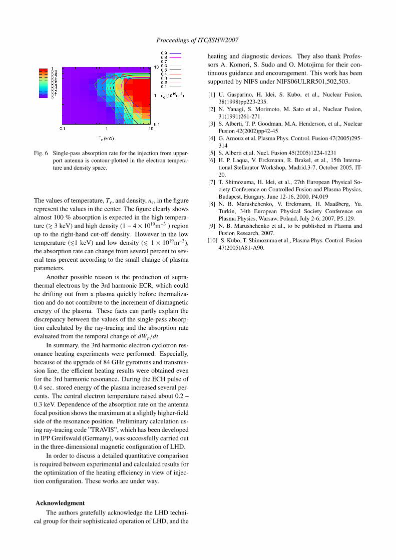
Fig. 4 Ray trace calculation together with mod-B contours andflux surfaces.
An X-mode is assumed to be perpendicularly injectedfrom the lower-port antenna focused on the magnetic axis.In Fig. 4, the configuration of calculation is illustrated withmod-B counters, flux surfaces and wave rays. The 3rdharmonic electron cyclotron resonance is also depicted.Calculated rays from the lower-port antenna are typicallyshown. The profile of the electron temperature is assumed(Te0 − Tea) × (1 − ρ3)1.5 + Tea with Te0=1.3 keV, whereρ = r/a is a normalized minor radius, and Te0 and Tea arethe electron temperature at the plasma center and the edge,respectively. The central electron density ne0 is assumedto be 1 × 10¹⁹m−3. The profile of the electron density wasassumed the same as the electron temperature.
The power absorption is localized near the 3rd har-monic resonance (B = 1 T) and the deposition is almostlimited within ρ ∼ 0.2, which is shown in Fig. 5 (a). Most
part of the power is absorbed by the passing electrons nearthe magnetic axis. A small fraction is absorbed by thetrapped electrons within ρ ∼ 0.2 and around ρ ∼ 0.4 − 0.5.The integrated absorbed power is shown in Fig. 5 (b). To-tal amount of the absorption power reaches 0.6 MW for1.3 MW injection. Maximum absorption rate is about50 %.
Fig. 5 Power deposition. (a) Deposited power density is plottedas a function of normalized minor radius and (b) integralvalue of absorbed power along the ray path. Total amountis decomposed into each component absorbed by passingand trapped electrons.
4. Discussion and summaryThe experimental results show the efficient heating at
the 3rd harmonic resonance even in the fairly low elec-tron temperature (∼ 1 keV) and low electron density (∼0.6 × 10¹⁹m−3). However experimentally obtained absorp-tion rate of about 20 % is lower than that expected by theray-tracing calculation, which was carried out in the realis-tic three-dimensional magnetic configuration of LHD. Onepossible reason of the discrepancy seems to be the differ-ences of values and profiles of the temperature and densityfor between the actual plasma and the modeled one. Be-cause the optical thickness scales as τ ∼ ne · T 2
e , a littletemperature change possibly leads to fairly large differenceof the absorption rate. Figure 6 shows a contour-plot of thesingle-pass absorption rate in the electron temperature anddensity space for the injection from the upper-port antennawith R f oc = 3.7 m. In these calculations the dispersion re-lation of a cold plasma was assumed for ray calculationand the weekly relativistic effect were included for the ab-sorption [10]. The profiles of the electron temperature anddensity are assumed to have the same ones such as (1−ρ2)2.
Proceedings of ITC/ISHW2007
Fig. 6 Single-pass absorption rate for the injection from upper-port antenna is contour-plotted in the electron tempera-ture and density space.
The values of temperature, Te, and density, ne, in the figurerepresent the values in the center. The figure clearly showsalmost 100 % absorption is expected in the high tempera-ture (& 3 keV) and high density (1 − 4 × 10¹⁹m−3 ) regionup to the right-hand cut-off density. However in the lowtemperature (.1 keV) and low density (. 1 × 10¹⁹m−3),the absorption rate can change from several percent to sev-eral tens percent according to the small change of plasmaparameters.
Another possible reason is the production of supra-thermal electrons by the 3rd harmonic ECR, which couldbe drifting out from a plasma quickly before thermaliza-tion and do not contribute to the increment of diamagneticenergy of the plasma. These facts can partly explain thediscrepancy between the values of the single-pass absorp-tion calculated by the ray-tracing and the absorption rateevaluated from the temporal change of dWp/dt.
In summary, the 3rd harmonic electron cyclotron res-onance heating experiments were performed. Especially,because of the upgrade of 84 GHz gyrotrons and transmis-sion line, the efficient heating results were obtained evenfor the 3rd harmonic resonance. During the ECH pulse of0.4 sec. stored energy of the plasma increased several per-cents. The central electron temperature raised about 0.2 –0.3 keV. Dependence of the absorption rate on the antennafocal position shows the maximum at a slightly higher-fieldside of the resonance position. Preliminary calculation us-ing ray-tracing code ”TRAVIS”, which has been developedin IPP Greifswald (Germany), was successfully carried outin the three-dimensional magnetic configuration of LHD.
In order to discuss a detailed quantitative comparisonis required between experimental and calculated results forthe optimization of the heating efficiency in view of injec-tion configuration. These works are under way.
AcknowledgmentThe authors gratefully acknowledge the LHD techni-
cal group for their sophisticated operation of LHD, and the
heating and diagnostic devices. They also thank Profes-sors A. Komori, S. Sudo and O. Motojima for their con-tinuous guidance and encouragement. This work has beensupported by NIFS under NIFS06ULRR501,502,503.
[1] U. Gasparino, H. Idei, S. Kubo, et al., Nuclear Fusion,38(1998)pp223-235.
[2] N. Yanagi, S. Morimoto, M. Sato et al., Nuclear Fusion,31(1991)261-271.
[3] S. Alberti, T. P. Goodman, M.A. Henderson, et al., NuclearFusion 42(2002)pp42-45
[4] G. Arnoux et al, Plasma Phys. Control. Fusion 47(2005)295-314
[5] S. Alberti et al, Nucl. Fusion 45(2005)1224-1231[6] H. P. Laqua, V. Erckmann, R. Brakel, et al., 15th Interna-
tional Stellarator Workshop, Madrid,3-7, October 2005, IT-20.
[7] T. Shimozuma, H. Idei, et al., 27th European Physical So-ciety Conference on Controlled Fusion and Plasma Physics,Budapest, Hungary, June 12-16, 2000, P4.019
[8] N. B. Marushchenko, V. Erckmann, H. Maaßberg, Yu.Turkin, 34th European Physical Society Conference onPlasma Physics, Warsaw, Poland, July 2-6, 2007, P5.129.
[9] N. B. Marushchenko et al., to be published in Plasma andFusion Research, 2007.
[10] S. Kubo, T. Shimozuma et al., Plasma Phys. Control. Fusion47(2005)A81-A90.


![i .] APPROXIMATING HARMONIC FUNCTIONS 499€¦ · APPROXIMATING HARMONIC FUNCTIONS 499 THE APPROXIMATION OF HARMONIC FUNCTIONS BY HARMONIC POLYNOMIALS AND BY HARMONIC RATIONAL FUNCTIONS*](https://static.fdocuments.net/doc/165x107/5f0873ba7e708231d42214c2/i-approximating-harmonic-functions-499-approximating-harmonic-functions-499-the.jpg)