Echo Analysis for Voice over IP -...
24
1 Echo Analysis for Voice over IP Echo Analysis for Voice over IP Version History Echo Analysis for Voice over IP defines echo and describes where it occurs in a voice network. It examines the basic aspects of echo analysis and describes the effects of various network elements on echo. This document also explains how echo is measured and how echo cancelers work to estimate and eliminate echo. It looks at customer and service provider expectations about echo, and explains how to configure gateways to minimize echo. It points out that the normal characteristics of packet-based networks might unmask preexisting problems in the time-division multiplexing (TDM)-based voice infrastructure. Finally, it outlines a process for locating and eliminating loud echos and long echos, and concludes with a real-life case study involving PBX-based echo in an international voice network. This document contains the following sections: • Echo Analysis Overview, page 1 • Echo Analysis Basics, page 2 • Effects of Network Elements on Echo, page 5 • Echo Canceler, page 8 • Customer Expectations About Echo, page 15 • Service Provider Expectations About Echo, page 15 • Configuring Gateways to Minimize Echo, page 16 • Process for Locating and Eliminating Echos, page 16 • Echo Analysis Case Study, page 18 • Related Documents, page 23 Echo Analysis Overview In a voice telephone call, an echo occurs when you hear your own voice repeated. An echo is the audible leak-through of your own voice into your own receive (return) path. This document discusses basic concepts applicable to echo analysis, explains echo cancelation, and provides a process for locating and eliminating echos. Version Number Date Notes 1 06/22/2001 This document was created.
Transcript of Echo Analysis for Voice over IP -...
ents onte andow to
ede, andk.
udible
, and
Echo Analysis for Voice over IP
Version History
Echo Analysis for Voice over IPdefines echo and describes where it occurs in a voice network. Itexamines the basic aspects of echo analysis and describes the effects of various network elemecho. This document also explains how echo is measured and how echo cancelers work to estimaeliminate echo. It looks at customer and service provider expectations about echo, and explains hconfigure gateways to minimize echo. It points out that the normal characteristics of packet-basnetworks might unmask preexisting problems in the time-division multiplexing (TDM)-based voicinfrastructure. Finally, it outlines a process for locating and eliminating loud echos and long echosconcludes with a real-life case study involving PBX-based echo in an international voice networ
This document contains the following sections:
• Echo Analysis Overview, page 1
• Echo Analysis Basics, page 2
• Effects of Network Elements on Echo, page 5
• Echo Canceler, page 8
• Customer Expectations About Echo, page 15
• Service Provider Expectations About Echo, page 15
• Configuring Gateways to Minimize Echo, page 16
• Process for Locating and Eliminating Echos, page 16
• Echo Analysis Case Study, page 18
• Related Documents, page 23
Echo Analysis OverviewIn a voice telephone call, an echo occurs when you hear your own voice repeated. An echo is the aleak-through of your own voice into your own receive (return) path.
This document discusses basic concepts applicable to echo analysis, explains echo cancelationprovides a process for locating and eliminating echos.
Version Number Date Notes
1 06/22/2001 This document was created.
1Echo Analysis for Voice over IP
Echo Analysis for Voice over IPEcho Analysis Basics
, there
nsmito the
ceiver's ear
, ther.arries
rn)
ndset.
elayworkceive
Echo Analysis BasicsEvery voice conversation has at least two participants. From the perspective of each participantare two voice paths in every call:
• Transmit path—The transmit path is also called the send or Tx path. In a conversation, the trapath is created when a person speaks. The sound is transmitted from the speaker's mouth tlistener's ear.
• Receive path—The receive path is also called the return or Rx path. In a conversation, the repath is created when a person hears the conversation. The sound is received by the listenefrom the speaker's mouth.
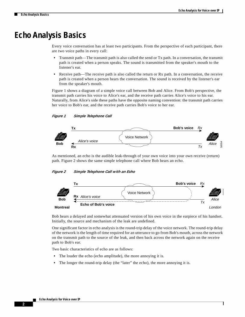
Figure 1 shows a diagram of a simple voice call between Bob and Alice. From Bob's perspectivetransmit path carries his voice to Alice's ear, and the receive path carries Alice's voice to his eaNaturally, from Alice's side these paths have the opposite naming convention: the transmit path cher voice to Bob's ear, and the receive path carries Bob's voice to her ear.
Figure 1 Simple Telephone Call
As mentioned, an echo is the audible leak-through of your own voice into your own receive (retupath. Figure 2 shows the same simple telephone call where Bob hears an echo.
Figure 2 Simple Telephone Call with an Echo
Bob hears a delayed and somewhat attenuated version of his own voice in the earpiece of his haInitially, the source and mechanism of the leak are undefined.
One significant factor in echo analysis is the round-trip delay of the voice network. The round-trip dof the network is the length of time required for an utterance to go from Bob's mouth, across the neton the transmit path to the source of the leak, and then back across the network again on the repath to Bob's ear.
Two basic characteristics of echo are as follows:
• The louder the echo (echo amplitude), the more annoying it is.
• The longer the round-trip delay (the “later” the echo), the more annoying it is.
Voice Network
Bob
Tx
Rx
Alice's voice
RxBob's voice
TxAlice
5655
4
Voice Network
Bob
Montreal
Tx
Rx Alice's voice
RxBob's voice
Echo of Bob's voiceTx
Alice
London
5655
5
2Echo Analysis for Voice over IP
Echo Analysis for Voice over IPLocating an Echo
smittics ofg theAlice
rk
s have
ls aretionsicaloise
le
with
pieceen theecho.
itorynomenad.
leaksecho
Locating an EchoIn Figure 2, Bob experiences the echo problem, which means that a signal is leaking from his tranpath into his receive path. The fact that Bob hears an echo illustrates one of the basic characterisecho: echo always indicates a problem at the other end of the call. The problem that is producinecho that Bob hears, the leakage source, is somewhere on Alice's side of the network (London). Ifwas experiencing echo, the problem would be on Bob's side (Montreal).
The echo leak is always in the terminating side of the network for the following reasons:
• Leak-through happens only in analog circuits. Voice traffic in the digital portions of the netwodoes not leak from one path into another.
Analog signals can leak from one path to another—electrically from one wire to another, oracoustically through the air from a loudspeaker to a microphone. When these analog signalbeen converted to digital bits, they do not leak.
All digital bits are represented by analog signals at the physical layer and these analog signasubject to leakage. The analog signals that represent bits can tolerate a good deal of distorbefore they become too distorted to be properly decoded. If such distortion occurred in the phylayer, the problem would not be echo. If you had connectivity at all, you would hear digital ninstead of a voice echo.
• Echos arriving after very short delays, about 20 milliseconds (ms), are generally imperceptibbecause they are masked by the physical and electrical sidetone signal.
This point is a corollary to the previous assertion that echos become increasingly annoying increasing mouth-to-ear delay. A certain minimum delay is needed for an echo to becomeperceptible. In almost every telephone device, some of the Tx signal is fed back into the earso that you can hear yourself speaking. This feedback is known as sidetone. The delay betweactual mouth signal and the sidetone signal is negligible, and sidetone is not perceived as an
Also, your skull resonates during speech (an acoustic sidetone source) and the human audsystem has a certain integration period that determines the minimum time difference betweeevents that will be perceived as separate events rather than a single one. Together, these phencreate a minimum mouth-to-ear delay of about 20 ms before an echo signal can be perceive
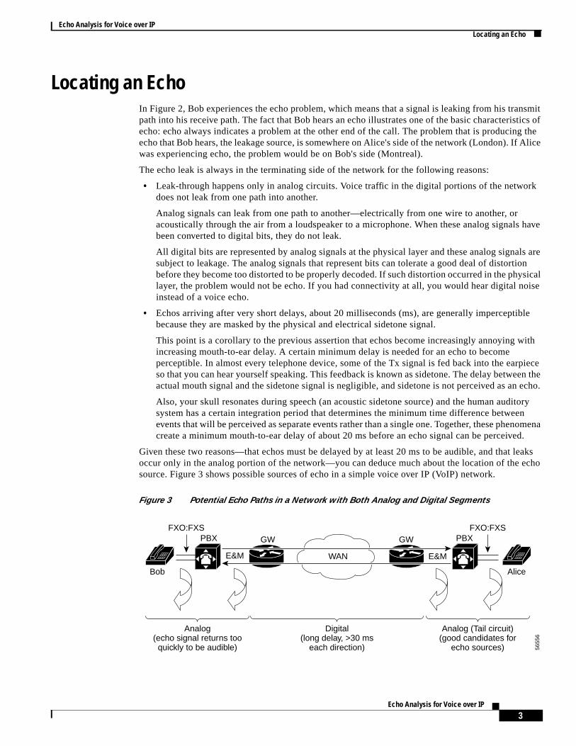
Given these two reasons—that echos must be delayed by at least 20 ms to be audible, and thatoccur only in the analog portion of the network—you can deduce much about the location of thesource. Figure 3 shows possible sources of echo in a simple voice over IP (VoIP) network.
Figure 3 Potential Echo Paths in a Network with Both Analog and Digital Segments
WAN
Digital(long delay, >30 ms
each direction)
Analog (Tail circuit)(good candidates for
echo sources)
Analog(echo signal returns too
quickly to be audible)
PBX PBXGW
E&M E&M
GW
Bob Alice
5655
6
FXO:FXS FXO:FXS
3Echo Analysis for Voice over IP
Echo Analysis for Voice over IPLocating an Echo
logionive
ughencylice's
ts doecho
e
elay of att thatcrossth int Bob
hone
and many
In this typical VoIP network, the digital packet portion of the network is located between two anatransmission segments. Bob in Montreal is connected by a 2-wire analog foreign exchange stat(FXS) circuit to a local PBX, which is connected to a local VoIP gateway by a 4-wire analog recEand transMit (E&M) circuit. The Montreal gateway communicates with the London gateway throan IP network. As we will discuss later, this packet transmission segment has an end-to-end latgreater than 30 ms. At the London end of the call, the gateway is connected in the same way to Atelephone (by E&M to the PBX and by FXS to the terminal).
The analog circuit in London is known as thetail circuit. It forms the tail or termination of the call fromthe perspective of the user experiencing the echo—Bob in this case.
Suppose you want to locate potential sources of echo in the network in Figure 3. You know that binot leak, so you can disqualify the digital segment of the system. Therefore, the leak causing Bob'smust be located in either the tail circuit in Montreal or the tail circuit in London. Any leak in theMontreal tail circuit would not have a long enough delay to be perceptible—echos there would bmasked by Bob's sidetone. So the source of the echo must be the London tail circuit.
Remember that an echo problem has three ingredients, as follows:
• An analog leakage path between analog Tx and Rx paths.
• Sufficient delay in echo return for echo to be perceived as annoying.
• Sufficient echo amplitude to be perceived as annoying.
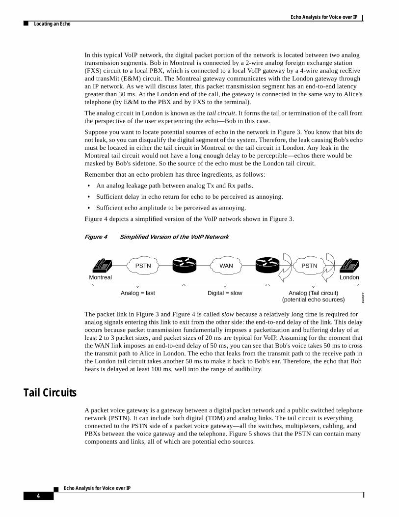
Figure 4 depicts a simplified version of the VoIP network shown in Figure 3.
Figure 4 Simplified Version of the VoIP Network
The packet link in Figure 3 and Figure 4 is calledslow because a relatively long time is required foranalog signals entering this link to exit from the other side: the end-to-end delay of the link. This doccurs because packet transmission fundamentally imposes a packetization and buffering delayleast 2 to 3 packet sizes, and packet sizes of 20 ms are typical for VoIP. Assuming for the momenthe WAN link imposes an end-to-end delay of 50 ms, you can see that Bob's voice takes 50 ms tothe transmit path to Alice in London. The echo that leaks from the transmit path to the receive pathe London tail circuit takes another 50 ms to make it back to Bob's ear. Therefore, the echo thahears is delayed at least 100 ms, well into the range of audibility.
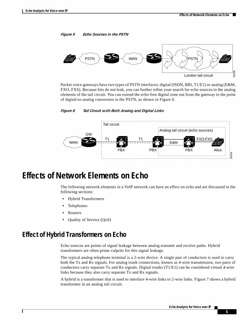
Tail CircuitsA packet voice gateway is a gateway between a digital packet network and a public switched telepnetwork (PSTN). It can include both digital (TDM) and analog links. The tail circuit is everythingconnected to the PSTN side of a packet voice gateway—all the switches, multiplexers, cabling, PBXs between the voice gateway and the telephone. Figure 5 shows that the PSTN can containcomponents and links, all of which are potential echo sources.
PSTN
Digital = slow Analog (Tail circuit)(potential echo sources)
Analog = fast
Montreal London
5655
7
WAN PSTN
4Echo Analysis for Voice over IP
Echo Analysis for Voice over IPEffects of Network Elements on Echo
&M,nalogoint
in the
arryirs of-wire
rid
Figure 5 Echo Sources in the PSTN
Packet voice gateways have two types of PSTN interfaces: digital (ISDN, BRI, T1/E1) or analog (EFXO, FXS). Because bits do not leak, you can further refine your search for echo sources to the aelements of the tail circuit. You can extend the echo-free digital zone out from the gateway to the pof digital-to-analog conversion in the PSTN, as shown in Figure 6.
Figure 6 Tail Circuit with Both Analog and Digital Links
Effects of Network Elements on EchoThe following network elements in a VoIP network can have an effect on echo and are discussedfollowing sections:
• Hybrid Transformers
• Telephones
• Routers
• Quality of Service (QoS)
Effect of Hybrid Transformers on EchoEcho sources are points of signal leakage between analog transmit and receive paths. Hybridtransformers are often prime culprits for this signal leakage.
The typical analog telephone terminal is a 2-wire device: A single pair of conductors is used to cboth the Tx and Rx signals. For analog trunk connections, known as 4-wire transmission, two paconductors carry separate Tx and Rx signals. Digital trunks (T1/E1) can be considered virtual 4links because they also carry separate Tx and Rx signals.
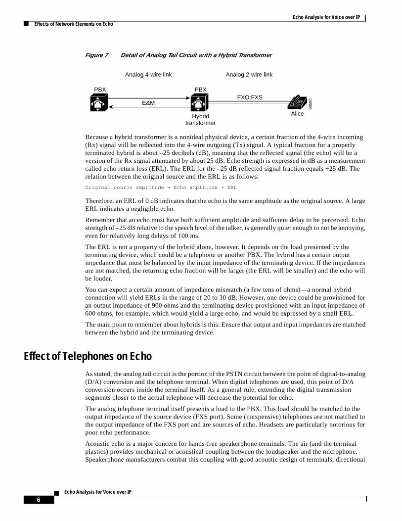
A hybrid is a transformer that is used to interface 4-wire links to 2-wire links. Figure 7 shows a hybtransformer in an analog tail circuit.
PSTN
London tail circuit 5655
8
WAN PSTN
Analog tail circuit (echo sources)
Tail circuit
5655
9
PBX PBX Alice
FXO:FXST1T1GW
E&M
PBX
WAN
5Echo Analysis for Voice over IP
Echo Analysis for Voice over IPEffects of Network Elements on Echo
ming
e arementhe
large
Echoying,
tanceswill
dfor
nce ofL.
tched
logA
o thehed tous for
inalne.
tional
Figure 7 Detail of Analog Tail Circuit with a Hybrid Transformer
Because a hybrid transformer is a nonideal physical device, a certain fraction of the 4-wire inco(Rx) signal will be reflected into the 4-wire outgoing (Tx) signal. A typical fraction for a properlyterminated hybrid is about –25 decibels (dB), meaning that the reflected signal (the echo) will bversion of the Rx signal attenuated by about 25 dB. Echo strength is expressed in dB as a measucalled echo return loss (ERL). The ERL for the –25 dB reflected signal fraction equals +25 dB. Trelation between the original source and the ERL is as follows:
Original source amplitude = Echo amplitude + ERL
Therefore, an ERL of 0 dB indicates that the echo is the same amplitude as the original source. AERL indicates a negligible echo.
Remember that an echo must have both sufficient amplitude and sufficient delay to be perceived.strength of –25 dB relative to the speech level of the talker, is generally quiet enough to not be annoeven for relatively long delays of 100 ms.
The ERL is not a property of the hybrid alone, however. It depends on the load presented by theterminating device, which could be a telephone or another PBX. The hybrid has a certain outpuimpedance that must be balanced by the input impedance of the terminating device. If the impedare not matched, the returning echo fraction will be larger (the ERL will be smaller) and the echobe louder.
You can expect a certain amount of impedance mismatch (a few tens of ohms)—a normal hybriconnection will yield ERLs in the range of 20 to 30 dB. However, one device could be provisionedan output impedance of 900 ohms and the terminating device provisioned with an input impeda600 ohms, for example, which would yield a large echo, and would be expressed by a small ER
The main point to remember about hybrids is this: Ensure that output and input impedances are mabetween the hybrid and the terminating device.
Effect of Telephones on EchoAs stated, the analog tail circuit is the portion of the PSTN circuit between the point of digital-to-ana(D/A) conversion and the telephone terminal. When digital telephones are used, this point of D/conversion occurs inside the terminal itself. As a general rule, extending the digital transmissionsegments closer to the actual telephone will decrease the potential for echo.
The analog telephone terminal itself presents a load to the PBX. This load should be matched toutput impedance of the source device (FXS port). Some (inexpensive) telephones are not matcthe output impedance of the FXS port and are sources of echo. Headsets are particularly notoriopoor echo performance.
Acoustic echo is a major concern for hands-free speakerphone terminals. The air (and the termplastics) provides mechanical or acoustical coupling between the loudspeaker and the microphoSpeakerphone manufacturers combat this coupling with good acoustic design of terminals, direc
5656
0
Alice
E&M
Analog 4-wire link Analog 2-wire link
FXO:FXSPBX PBX
Hybridtransformer
6Echo Analysis for Voice over IP
Echo Analysis for Voice over IPEffects of Network Elements on Echo
eryho
gitalos.uslynalogX. It the
thersameds,
ing ofn thecho
h is
trip
ptible
re 3.d therted1 mssendsre, thecketandthe
ver.kets late,ouldld be
gert, or
20 ms
microphones, and acoustic echo cancelers and suppressors in the terminal. However, this is a vdifficult problem and speakerphones are inherently good echo sources. If you are hunting an ecproblem and the terminating tail circuit involves a speakerphone, eliminate the speakerphone.
Effects of Routers on EchoThe belief that adding routers to a voice network creates echos is a common misconception. Disegments of the network do not cause leaks; so technically, routers cannot be the source of echAdding routers to the network, though, adds delay to the network—delay that can make a previoimperceptible echo perceptible. The gateway itself does not add echo unless you are using an ainterface to the PSTN and the output impedance is incorrectly provisioned with respect to the PBis more likely that the echo was already in the analog tail circuit but was imperceptible becauseround-trip delay was less than 20 ms.
For example, suppose you were visiting London and you wanted to call a friend who lived on the oside of town. This call is echo free. But when you call the same friend (whose telephone is on thetail circuit) from the U.S. over a satellite link with a round-trip delay of several hundred milliseconthe echo is obvious and annoying. The only change has been the insertion of delay.
VoIP technologies impose a fundamental transmission delay due to packetization and the bufferreceived packets before playout at the receiving endpoint. This delay is generally much smaller thadelay associated with satellite links—but it is usually sufficient to make a previously unnoticeable eobjectionable.
End-to-End Voice Call Delays
Analog transmission is very fast, limited only by the propagation speed of electrons in a wire (whicslightly lower than the speed of light, but still very fast) or photons in a fiber-optic link. TDMtransmission is similarly very quick. A transcontinental PSTN call in the U.S. has a typical round-delay of about 10 to 20 ms. A local PSTN call has a shorter typical round-trip delay of only a fewmilliseconds. Such short delays mean that even relatively loud echos in the PSTN remain imperceas echo because they are masked by sidetone.
Imagine a call between Bob and Alice over a VoIP transmission link such as the one shown in FiguConsider the path Bob's voice takes from Montreal to London. Bob speaks into his mouthpiece ananalog signal arrives at the Montreal PBX within 1 ms. At the PBX, his analog voice signal is conveto a digital pulse code modulation (PCM) stream and arrives at the Montreal IP gateway after onlymore of delay. So Bob's voice takes 2 ms to go from his mouth to the voice gateway. The gatewayout packets every 20 ms, which means that each packet contains 20 ms of voice payload. Therefovoice gateway must wait to collect 20 ms of Bob's voice before it can fill the first packet. The first paleaves the Montreal gateway 22 ms after Bob starts talking. Assuming that the WAN is very quickuncongested, this first packet arrives at the London voice gateway after only 5 ms of transit. So London gateway gets the packet 27 ms after Bob starts speaking.
This packet is not played out from the London gateway to Alice immediately upon receipt, howeThe Montreal gateway delivers new packets faithfully at 20 ms intervals, but the vagaries of pactransmission mean that packets arrive in London at non-constant intervals: packet 2 might be 1 mpacket 3 might be 4 ms late, and so on. If the London gateway played out packet 1 immediately, it wbe caught short 20 ms later when packet 2 was due but had not yet arrived—and Bob's voice wouinterrupted.
The London gateway puts incoming packets into a buffer. The deeper the playout buffer, the lonpackets will wait before being played. The minimum buffer depth you can safely use is one packe20 ms in our case. So packet 1 arrives at time 27 ms and is played out to the London PSTN tail
7Echo Analysis for Voice over IP
Echo Analysis for Voice over IPEcho Canceler
N tothe
thecrease
m ofne
er
packetd theyudibleecausening.
heelay
erentnnot,
eakedtoof the
later at time 47 ms. It takes 2 more milliseconds to go from the London gateway across the PSTAlice's earpiece, for a total of 49 ms for Bob's words to go from Bob's mouth to Alice's ear. This isend-to-end delay of the voice transmission system: 45 ms in the WAN and 4 ms in the PSTN.
You could increase the packet transmission rate to reduce the end-to-end delay, but increasing packet transmission rate would increase the bandwidth necessary for the call because it would inthe ratio of header size (which is a constant) to payload size (which you would reduce).
As a general rule, the end-to-end latency for a packet transmission link has a fundamental minimuabout 2 to 3 packet sizes (in milliseconds). Even if the packet transit time was instantaneous, opacket’s worth of time still is required to fill the first packet. Even an unrealistically ideal,“fast-as-light” gateway and network face this fundamental, minimum delay.
Any echo source in the London tail circuit, will go all the way back across the WAN, facing anoth47 ms of delay. The echo will return to Bob's earpiece after a round trip—almost 100 ms ofdelay—which is quite enough to make the echo audible.
Therefore, the use of a packet transmission link imposes an extra delay of at least two to three sizes that was not present before. Echos occur in the analog tail circuit, not the packet network, anexisted before any routers were added. Adding the delay makes the existing, inaudible echo an aecho. The delay of the packet network cannot be reduced below a fundamental limit. Cisco voicgateways already operate very close to this minimum delay (50 to 80 ms end-to-end is typical). Beof these long delays, all VoIP gateways employ echo cancelers to reduce the amplitude of returechos. However, the best solution to echo problems always is to remove the source of the echo
In summary, remember the following effects:
• Network delay increases user annoyance for an echo of equal strength.
• Adding routers does not cause echo; it exacerbates existing echo problems.
Effect of QoS on EchoQoS might improve your end-to-end network delay for a given level of congestion—the shorter tdelay, the less annoying a given echo becomes. However, you will never be able to reduce the dbelow the “danger zone” for echo perception with any form of QoS because the minimum delay inhin VoIP networks is long enough for echos to be perceptible. QoS can help in other ways, but it caby itself, eliminate echo.
Echo CancelerAn echo canceler is a component of a voice gateway that reduces the level of echos that have lfrom the Rx path (from the gateway out into the tail circuit) into the Tx path (from the tail circuit inthe gateway). Rx and Tx here are from the perspective of the voice gateway—London, in the caseexamples thus far described.
Echo cancelers have the following properties:
• Echo cancelers face into the PSTN tail circuit.
• An echo canceler eliminates echos in the tail circuit on its side of the network.
Figure 8 shows the location of the echo canceler in London.
8Echo Analysis for Voice over IP
Echo Analysis for Voice over IPEcho Canceler
oice the
le forhreal
ircuitristicsho. Bob'souldf the
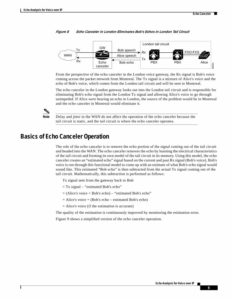
Figure 8 Echo Canceler in London Eliminates Bob's Echos in London Tail Circuit
From the perspective of the echo canceler in the London voice gateway, the Rx signal is Bob's vcoming across the packet network from Montreal. The Tx signal is a mixture of Alice's voice andecho of Bob's voice, which comes from the London tail circuit and will be sent to Montreal.
The echo canceler in the London gateway looks out into the London tail circuit and is responsibeliminating Bob's echo signal from the London Tx signal and allowing Alice's voice to go througunimpeded. If Alice were hearing an echo in London, the source of the problem would be in Montand the echo canceler in Montreal would eliminate it.
Note Delay and jitter in the WAN do not affect the operation of the echo canceler because thetail circuit is static, and the tail circuit is where the echo canceler operates.
Basics of Echo Canceler OperationThe role of the echo canceler is to remove the echo portion of the signal coming out of the tail cand headed into the WAN. The echo canceler removes the echo by learning the electrical characteof the tail circuit and forming its own model of the tail circuit in its memory. Using this model, the eccanceler creates an “estimated echo” signal based on the current and past Rx signal (Bob's voice)voice is run through this functional model to come up with an estimate of what Bob's echo signal wsound like. This estimated “Bob echo” is then subtracted from the actual Tx signal coming out otail circuit. Mathematically, this subtraction is performed as follows:
Tx signal sent from the gateway back to Bob
= Tx signal – “estimated Bob's echo”
= (Alice's voice + Bob's echo) – “estimated Bob's echo”
= Alice's voice + (Bob's echo – estimated Bob's echo)
= Alice's voice (if the estimation is accurate)
The quality of the estimation is continuously improved by monitoring the estimation error.
Figure 9 shows a simplified version of the echo canceler operation.
London tail circuit
5656
1PBX Alice
FXO:FXSBob speech
Alice speech
Bob echo
TxRx
TxRx
GW
Echocanceler
PBX
WAN
9Echo Analysis for Voice over IP
Echo Analysis for Voice over IPEcho Canceler
boxthet
ould
taile realtain
ler haschorror
rror.ptive
uess
ing inand
ands the
ailtalkncet ofais way,rom
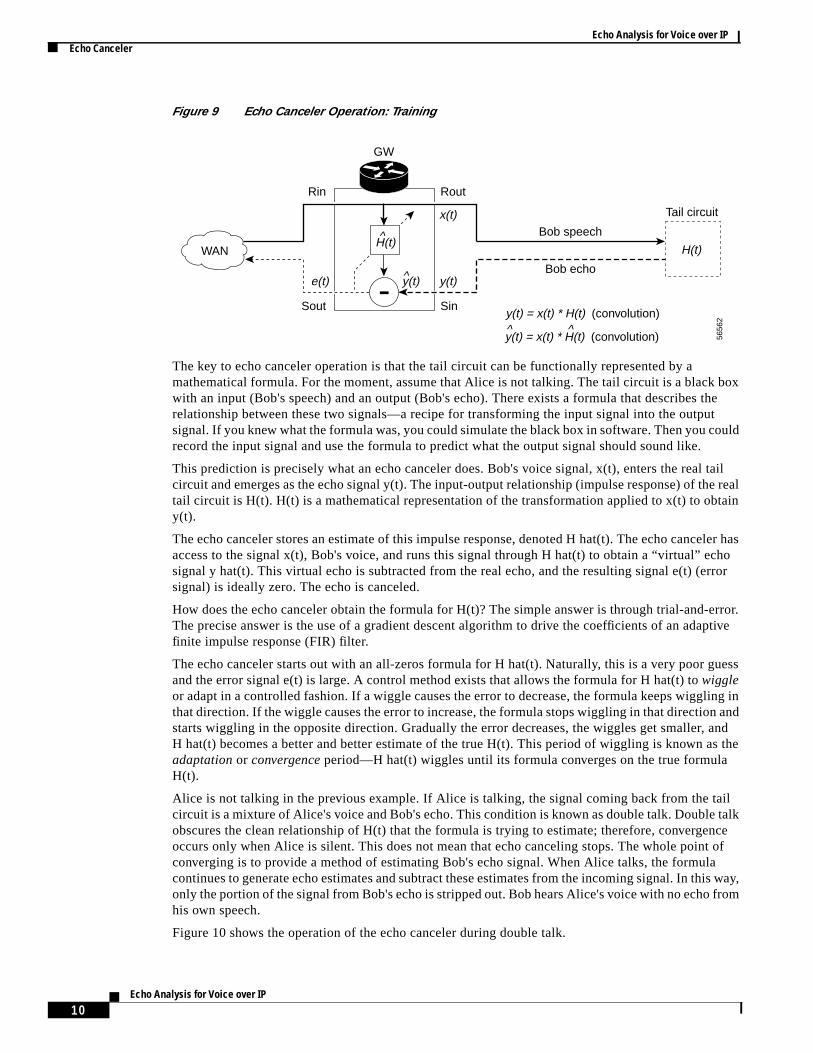
Figure 9 Echo Canceler Operation: Training
The key to echo canceler operation is that the tail circuit can be functionally represented by amathematical formula. For the moment, assume that Alice is not talking. The tail circuit is a blackwith an input (Bob's speech) and an output (Bob's echo). There exists a formula that describes relationship between these two signals—a recipe for transforming the input signal into the outpusignal. If you knew what the formula was, you could simulate the black box in software. Then you crecord the input signal and use the formula to predict what the output signal should sound like.
This prediction is precisely what an echo canceler does. Bob's voice signal, x(t), enters the realcircuit and emerges as the echo signal y(t). The input-output relationship (impulse response) of thtail circuit is H(t). H(t) is a mathematical representation of the transformation applied to x(t) to oby(t).
The echo canceler stores an estimate of this impulse response, denoted H hat(t). The echo canceaccess to the signal x(t), Bob's voice, and runs this signal through H hat(t) to obtain a “virtual” esignal y hat(t). This virtual echo is subtracted from the real echo, and the resulting signal e(t) (esignal) is ideally zero. The echo is canceled.
How does the echo canceler obtain the formula for H(t)? The simple answer is through trial-and-eThe precise answer is the use of a gradient descent algorithm to drive the coefficients of an adafinite impulse response (FIR) filter.
The echo canceler starts out with an all-zeros formula for H hat(t). Naturally, this is a very poor gand the error signal e(t) is large. A control method exists that allows the formula for H hat(t) towiggleor adapt in a controlled fashion. If a wiggle causes the error to decrease, the formula keeps wigglthat direction. If the wiggle causes the error to increase, the formula stops wiggling in that directionstarts wiggling in the opposite direction. Gradually the error decreases, the wiggles get smaller,H hat(t) becomes a better and better estimate of the true H(t). This period of wiggling is known aadaptation or convergence period—H hat(t) wiggles until its formula converges on the true formulaH(t).
Alice is not talking in the previous example. If Alice is talking, the signal coming back from the tcircuit is a mixture of Alice's voice and Bob's echo. This condition is known as double talk. Doubleobscures the clean relationship of H(t) that the formula is trying to estimate; therefore, convergeoccurs only when Alice is silent. This does not mean that echo canceling stops. The whole poinconverging is to provide a method of estimating Bob's echo signal. When Alice talks, the formulcontinues to generate echo estimates and subtract these estimates from the incoming signal. In thonly the portion of the signal from Bob's echo is stripped out. Bob hears Alice's voice with no echo fhis own speech.
Figure 10 shows the operation of the echo canceler during double talk.
5656
2
WAN
GW
Rin
Bob speech
Tail circuit
Bob echo
Sout
Rout
Sin
H(t)H(t)
^
y(t)e(t) y(t)
y(t) = x(t) * H(t) (convolution)
y(t) = x(t) * H(t) (convolution)
x(t)
^
^ ^
-
10Echo Analysis for Voice over IP
Echo Analysis for Voice over IPEcho Canceler
useel of
y theevel ofler. It
d the
echok.
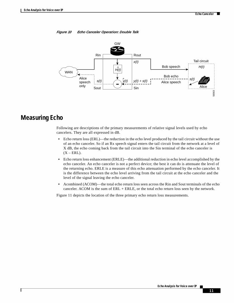
Figure 10 Echo Canceler Operation: Double Talk
Measuring EchoFollowing are descriptions of the primary measurements of relative signal levels used by echocancelers. They are all expressed in dB.
• Echo return loss (ERL)—the reduction in the echo level produced by the tail circuit without theof an echo canceler. So if an Rx speech signal enters the tail circuit from the network at a levX dB, the echo coming back from the tail circuit into the Sin terminal of the echo canceler is(X – ERL).
• Echo return loss enhancement (ERLE)—the additional reduction in echo level accomplished becho canceler. An echo canceler is not a perfect device; the best it can do is attenuate the lthe returning echo. ERLE is a measure of this echo attenuation performed by the echo canceis the difference between the echo level arriving from the tail circuit at the echo canceler anlevel of the signal leaving the echo canceler.
• Acombined (ACOM)—the total echo return loss seen across the Rin and Sout terminals of thecanceler. ACOM is the sum of ERL + ERLE, or the total echo return loss seen by the networ
Figure 11 depicts the location of the three primary echo return loss measurements.
5656
3
WAN
GW
Rin
Bob speech
Bob echo
Tail circuit
AliceAlice speech
Sout
Alicespeechonly
Rout
Sin
H(t)H(t)^
y(t)s(t) s(t)y(t) + s(t)
x(t)
^
-
11Echo Analysis for Voice over IP
Echo Analysis for Voice over IPEcho Canceler
fectchosos
ailt is
althewill
to27cuit
f echohen
ly, thethe
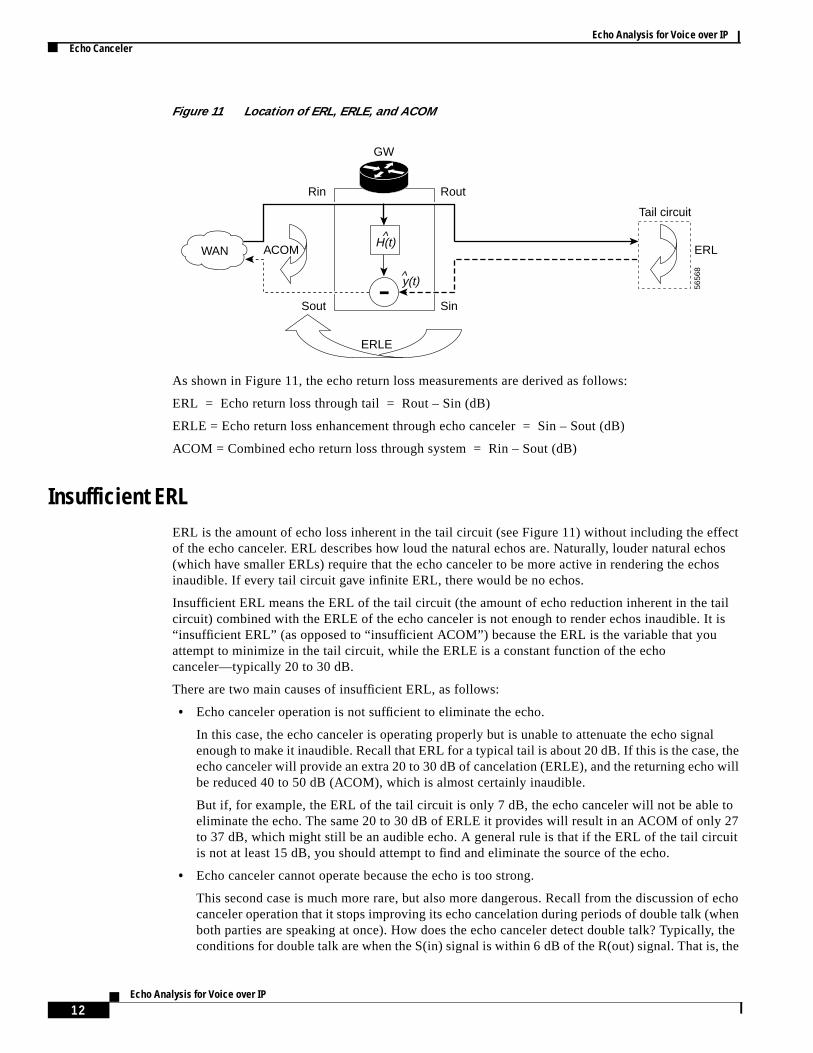
Figure 11 Location of ERL, ERLE, and ACOM
As shown in Figure 11, the echo return loss measurements are derived as follows:
ERL = Echo return loss through tail = Rout – Sin (dB)
ERLE = Echo return loss enhancement through echo canceler = Sin – Sout (dB)
ACOM = Combined echo return loss through system = Rin – Sout (dB)
Insufficient ERLERL is the amount of echo loss inherent in the tail circuit (see Figure 11) without including the efof the echo canceler. ERL describes how loud the natural echos are. Naturally, louder natural e(which have smaller ERLs) require that the echo canceler to be more active in rendering the echinaudible. If every tail circuit gave infinite ERL, there would be no echos.
Insufficient ERL means the ERL of the tail circuit (the amount of echo reduction inherent in the tcircuit) combined with the ERLE of the echo canceler is not enough to render echos inaudible. I“insufficient ERL” (as opposed to “insufficient ACOM”) because the ERL is the variable that youattempt to minimize in the tail circuit, while the ERLE is a constant function of the echocanceler—typically 20 to 30 dB.
There are two main causes of insufficient ERL, as follows:
• Echo canceler operation is not sufficient to eliminate the echo.
In this case, the echo canceler is operating properly but is unable to attenuate the echo signenough to make it inaudible. Recall that ERL for a typical tail is about 20 dB. If this is the case,echo canceler will provide an extra 20 to 30 dB of cancelation (ERLE), and the returning echobe reduced 40 to 50 dB (ACOM), which is almost certainly inaudible.
But if, for example, the ERL of the tail circuit is only 7 dB, the echo canceler will not be ableeliminate the echo. The same 20 to 30 dB of ERLE it provides will result in an ACOM of onlyto 37 dB, which might still be an audible echo. A general rule is that if the ERL of the tail ciris not at least 15 dB, you should attempt to find and eliminate the source of the echo.
• Echo canceler cannot operate because the echo is too strong.
This second case is much more rare, but also more dangerous. Recall from the discussion ocanceler operation that it stops improving its echo cancelation during periods of double talk (wboth parties are speaking at once). How does the echo canceler detect double talk? Typicalconditions for double talk are when the S(in) signal is within 6 dB of the R(out) signal. That is,
5656
8
WAN
GW
Rin
Tail circuit
Sout
ACOM ERL
ERLE
Rout
Sin
H(t)^
y(t)^
-
12Echo Analysis for Voice over IP
Echo Analysis for Voice over IPEcho Canceler
ERLecho..
thate echo
at thege asinate.
and
f echocome
fples
nging
in thenes at
Theer the
r atithh,chos
chos
combined Alice + echo signal is almost as loud or louder than Bob's voice. Therefore, if theis less than 6 dB, the echo signal will be considered to be a proper part of the call and not anSo the echo is declared double talk, and the echo canceler will never attempt to eliminate it
In summary, smaller ERL means louder natural echo. The louder the natural echo, the more likelyusers will be annoyed by echos with the same degree of cancelation. For extremely loud echos, thcanceler can be fooled into double-talk mode and will not converge.
Echo Canceler CoverageEcho canceler coverage (also known as tail coverage or tail length) specifies the length of time thecho canceler stores its approximation of an echo, H hat(t), in memory. You can think of coverathe echo canceler's cache. It is the maximum echo delay that an echo canceler will be able to elim
Previously we noted that the echo canceler faces into a static tail circuit. A tail circuit has an inputan output. If a word enters a tail circuit (signal x(t) in Figure 10), the echo (output signal y(t) inFigure 10) is a series of delayed and attenuated versions of that word, depending on the number osources and the delays associated with them. After a certain period of time, no more signal will out. This time period is known as theringing time of the tail circuit.
Think of the original echo source as a pebble tossed in still water and the echos as the series oattenuated ripples that the pebble produces. The ringing time is the time required for all of the ripto disperse.
Therefore, to fully eliminate all echos, the coverage of the echo canceler must be as long as the ritime of the tail circuit.
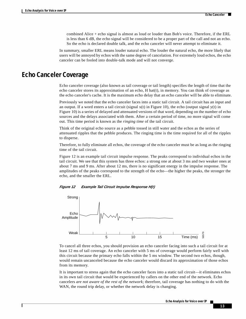
Figure 12 is an example tail circuit impulse response. The peaks correspond to individual echostail circuit. We see that this system has three echos: a strong one at about 3 ms and two weaker oabout 7 ms and 9 ms. After about 12 ms, there is no significant energy in the impulse response.amplitudes of the peaks correspond to the strength of the echo—the higher the peaks, the strongecho, and the smaller the ERL.
Figure 12 Example Tail Circuit Impulse Response H(t)
To cancel all three echos, you should provision an echo canceler facing into such a tail circuit foleast 12 ms of tail coverage. An echo canceler with 5 ms of coverage would perform fairly well wthis circuit because the primary echo falls within the 5 ms window. The second two echos, thougwould remain uncanceled because the echo canceler would discard its approximation of those efrom its memory.
It is important to stress again that the echo canceler faces into a static tail circuit—it eliminates ein its own tail circuit that would be experienced by callers on the other end of the network. Echocancelersare not aware of the rest of the network; therefore, tail coverage has nothing to do with theWAN, the round trip delay, or whether the network delay is changing.
EchoAmplitude
Strong
Weak5 10 15 Time (ms) 56
579
13Echo Analysis for Voice over IP
Echo Analysis for Voice over IPEcho Canceler
r ofoIPdded
echo
time
g thatr thende
andd ofking
earhouldature
ircuite tail
.
ud oroking
teste
ler is
).voice
Many people assume incorrectly that the long delays associated with VoIP require that the echocancelers have equally long tail coverage. However,only the tail determines the needed coverage.Remember that analog transmission is very quick—almost all simple tails ring for only a fewmilliseconds. Longer ringing times exist when the tail is very complex (for example, a large numbePSTN hops, multiple D/A conversions), or when it contains long-distance trunks. If the tail of your Vsystem contains another VoIP link, then your tail will be far too long to cover. In that case, the embeVoIP link requires its own echo canceler on its own tail.
We recommend that you avoid such embedded VoIP links. We suggest that you provision all yourcancelers to their maximum tail coverage all the time.
Uncancelable EchoAn uncancelable echo is an echo that is either too loud to render inaudible or delayed beyond thewindow of the echo canceler's coverage.
If the echo is too loud, it can require more attenuation than an echo canceler can provide—meanineither the echo canceler will be unable to make the echo imperceptible or that the echo will triggedouble-talk detector. Tail circuits that involve multiple PSTN hops, some long distance trunks, aalternating series of digital and analog links can have ringing times that exceed the tail coveragwindow.
Verifying Echo Canceler OperationThe quickest way to determine if you have a working echo canceler in the circuit is to make a callimmediately begin to say something like “TAH TAH FISH” repeatedly. The person on the other enthe line should be silent. If you are calling a voice-mail system, wait for the announcer to stop talbefore starting the experiment.
If the terminating tail circuit has cancelable echos and if the echo canceler is enabled, you will hecho for the first few utterances and then it will die away. After a few seconds of speech, the echo sbe gone or at least very quiet compared to the echo level at the beginning of the call. This is the signof a working echo canceler. Recall that an echo canceler starts out with no knowledge of the tail cthat it is looking into. It needs to observe a certain amount of speech and echo flowing through thcircuit to form the virtual tail circuit model. This training period is known as theconvergence time ofthe echo canceler. You should expect convergence within the first few seconds of active speech
If you try this experiment and do not obtain echo reduction with time, there are two possibleexplanations: the echo canceler is disabled or broken, or the echo is uncancelable (either too lodelayed beyond the tail coverage of the canceler). Try making calls to other destinations and lofor the standard “echo die away” behavior.
The surest way to determine if your echo canceler is working is to first run the previously describedwhen the echo canceler is off, and then again when the echo canceler is on. If you do not find thstandard “echo die away” behavior, then perform following steps to determine if your echo canceworking:
1. Telnet to the destination voice gateway and check the provisioning of the voice ports (POTS(Remember, the echo canceler you are interested in is the echo canceler in the destination gateway.)
2. Disable the echo canceler by issuing theno echo-cancel enablevoice-port command, then shutdown and reopen the voice port by issuing theshutdown andno shutdown commands.
14Echo Analysis for Voice over IP

Echo Analysis for Voice over IPCustomer Expectations About Echo
Hhave
eecho
e thetinyursty
orerent.onormal
monratedions for
ort will
honeomersiderk, and
knowircuit
sy totencyion
g. Ift doesle
3. Make a call to a destination telephone and listen for echo by saying something like “TAH TAFISH.” If you do not hear any echo, try different destination phones until you do. When you found an echo that persists throughout the call, save the destination number.
4. Reenable the echo canceler by using theecho-cancel enablevoice-port command, set coverage tomaximum by using theecho-cancel coveragevoice-port command, and shut down and reopen thvoice port. You should hear the echo die away within the first few seconds of speech. If the persists, the problem is in your echo canceler.
If the echo diminishes but is still noticeable, try to locate the source of the echo path and eliminatecho. Clearly, the echo canceler is working but it is unable to give sufficient ERLE. Occasionally,bursts of echo might emerge during the conversation, especially if the talker makes a quick, loud, bsound. This is normal echo canceler behavior. If these types of echos are loud enough to beunacceptable, you need to identify and eliminate the source of the echo in the tail circuit.
Customer Expectations About EchoBecause of the fundamental delays associated with VoIP technologies, existing echos will be mannoying than with TDM, and even the normal operation of an echo canceler will be more appaCustomers of VoIP networks need to be educated to expect the standard echo canceler operatipreviously described so that they do not confuse these types of echos with abnormal echos. Abnechos persist throughout a call and do not fade.
Service Provider Expectations About EchoEcho problems are relatively rare in the PSTN, which has short delays; they are much more comover cellular and satellite long distance calls. Interestingly, they are also much more readily tolein cellular and long distance calls because customers have been educated to have lower expectatsuch calls.
As long as VoIP calls continue to be terminated in analog tails, echo will be a problem. One majobstacle to widespread VoIP implementation is that many tail circuits have preexisting delays thabecome noticeable only when service providers introduce digital segments to the networks.
These problems will gradually be solved as digital networks extend out toward homes and telependpoints. Until then, how much echo can you expect? One call in 50? 100? 1000? Even if custare trained to complain only when an echo problem is persistent and repeatable, a service provcannot hunt down and destroy every echo complaint. No one has sufficient resources to do this tashunting down an echo is a necessarily intrusive process.
The challenge is to determine when an echo complaint is both solvable and worth solving. You that the echo source is in the destination tail circuit. For an echo problem to be solved, the tail cneeds to be accessible.
In an enterprise application where the PBXs are in the basement, for example, it is relatively easolve echo problems by examining levels and impedances in the customer PBX. Look for consisand commonality in the echo problems. If every call going through a particular PBX or transmisslink exhibits echo, then you can concentrate on that particular link. That is a problem worth solvinyou receive an isolated echo complaint for a particular destination phone number in the PSTN thanot share any links with other echo complaints, then you might find yourself hunting down a singtelephone echo complaint, which is usually not worth the resources.
15Echo Analysis for Voice over IP
Echo Analysis for Voice over IPConfiguring Gateways to Minimize Echo
ints,
tworkting
ann echo
teway
hists or
g theoice
, butle).
oicelsce in
cess
it on
set, thisuality
t the
ho
n
The goal of service providers in eliminating echos, therefore, is to identify clusters of echo complalook for common links, and then fix the echos. A PSTN has manydirty tails, and it is unrealistic toexpect that every echo can be eliminated. The best that you can do is to make sure that your own neand tails are clean, which requires care in installation and provisioning, especially when connecgateways to analog equipment.
Configuring Gateways to Minimize EchoEchos live in the analog tail circuit, not in the gateway. The gateway has an echo canceler that cattenuate manageable echos, but gateways cannot affect the root causes of the echo problems. Aon a gateway can be fixed in only two ways:
• Ensure that the echo canceler is enabled with maximum coverage.
• Match output impedances and levels with the analog telecom equipment attached to the gaanalog voice ports.
You can adjust the audio levels of voice ports to help eliminate echos, but you should consider tmethod more of a workaround than a solution. You can adjust the audio level of either the outputhe inputs of a voice port on a gateway.
Lowering the Sin input audio level (also calledincreasing the input attenuation or adding a loss pad)correspondingly decreases the level of any echos (increases the ERL of the tail). However, lowerinSin input audio level also decreases the audio level of the Tx speech signal for every call (Alice's vin this example).
Similarly, lowering the Rout output audio level correspondingly decreases the level of any echosalso decreases the audio level of the Rx speech signal for every call (Bob's voice in this examp
In the end, you could be helping the echo canceler for calls to tails with poor ERL, but hurting vquality by reducing levels forall calls through that particular voice port. You should adjust audio leveto alleviate echos only as a temporary workaround while you attempt to eliminate the echo sourthe tail circuit.
Process for Locating and Eliminating EchosBefore we look at the process for eliminating echos in the tail circuit, we will summarize the profor dealing with echos in general:
1. Identify which tail circuit is causing the echo. Remember, the echo is caused by the tail circuthe opposite side of the network from the caller hearing the echo.
2. Check for speakerphones or headsets. If the destination telephone is a speakerphone or headis probably the source of the echo. Try replacing the speakerphone or headset with a better qhandset and see if the echo dies away normally.
3. Telnet to the destination voice gateway and check that the echo canceler is enabled and thacoverage is set to maximum.
4. Test for normal echo canceler behavior as described in the preceding section, “Verifying EcCanceler Operation.”
If the echo persists, and you have verified that the echo canceler is working properly, you caconclude that the echo canceler cannot fix the echo for one of two reasons:
• The echo is too loud (called aloud echo).
16Echo Analysis for Voice over IP
Echo Analysis for Voice over IPProcess for Locating and Eliminating Echos
ausege ofr, when, or
echo
ss
eastthe
istent, to be
loudeable.e ERLecho.
longturned
rrm,
• The echo is too delayed (called along echo).
5. Identify which type of echo you are experiencing, either long or loud.
6. Eliminate the echo source.
After you have verified that the echo canceler is working properly, you still need to determine the cof the echo: Is the problem insufficient ERL in the tail, or is the echo delayed beyond the coverathe echo canceler? Most persistent echos are loud echos. Delayed echos are common, howevethe tail circuit involves a long-distance PSTN link, a series of alternating digital and analog linksany other link with high latency.
Identifying a Loud EchoYou can use the voice gateway itself to measure the ERL of the tail circuit by using the gatewaycanceler statistics reporting function. For a Cisco VoIP gateway, output from theshow call active voiceexec command contains valuable statistics.
To generate these statistics, first establish a voice call over the gateway. Then type theshow call activevoice exec command without pressing theReturn key. Make a loud continuous sound into themouthpiece or hold down a button on your touch-tone keypad to generate a sound, and then preReturn to display the call statistics.
Note You can also use commercial test devices (including handheld telecom level meters) tomeasure ERL for a particular destination circuit.
Remember, you need to look at thedestination voice gateway. Figure 12 shows that the ERL is thedifference in the reported Tx and Rx levels. Ideally, you want your gateway to have an ERL of at l15 dB. If your ERL is less than 10 dB, you probably have insufficient ERL in the tail circuit. Repeattest outlined in the previous paragraph using louder and softer noises and verify that the ERL isconsistent and that when you vary your volume, the levels vary accordingly. If these tests are consyou can be confident that the tail circuit is not providing enough echo loss for the echo cancelerable to eliminate the echo.
Identifying a Long EchoYou can identify a long echo problem with a technique similar to the one described previously forechos. The signature of a loud echo problem is that the echo is somewhat attenuated but still noticThe echo is the same regardless of whether the echo canceler is enabled. If you determine that this reasonable (greater than 10 dB) but the echo is still persistent, then the problem might be a long
If the problem is a long echo, there is not much that you can do to solve it. If the tail includes a distance hop, make sure that the PBX terminating the long distance hop has its own echo canceleron. If possible, extend the digital portion of your network as close as possible to the endpoint.
Locating and Eliminating Echos in the Tail CircuitBecause of the variety of possible network scenarios, it is difficult to give specific instructions fofinding and eliminating an echo in a tail circuit. There are some general steps that you can perfohowever, to track down the source of an echo and eliminate it.
17Echo Analysis for Voice over IP
Echo Analysis for Voice over IPEcho Analysis Case Study
on
fy the
callsto theracewaysisk.
ho in
sels,ausevoicee to the save
ls.
er. InQoS
e
so theTheuraths
Draw a diagram of the tail circuit, including all the digital and analog links between the destinativoice gateway and the destination telephone. This diagram will likely form a tree; from the voicegateway out, each device will have one or more potential destination branches. You need to identibreak point off the main branch for which calls give consistent echo.
For example, the gateway might be connected to a PBX with three output cards. If many of the through one of these ports exhibit echo, then you have narrowed the source of the problem tail circuits attached to that voice port. Look for clusters of echo associated with common links. If you tyour tail out to the uncontrolled PSTN, then remember that a certain percentage of PSTN tails alwill not provide sufficient ERL and you will be unable to correct them. When you find a link that giving insufficient ERL, examine the levels and provisioning of the devices at both ends of the lin
Echo Analysis Case StudyThe following case study describes how Cisco worked with an enterprise customer to eliminate eca VoIP network. The customer is a large manufacturing company with headquarters in Reading,Pennsylvania, and several plants in the United States and overseas. One plant, located in BrusBelgium, previously used the PSTN for intersite calling, which resulted in high toll charges. Becthe customer already had a data network in place, the logical choice was to implement a combinedand data network. Because traffic at the headquarters was required to cross the Ethernet backbonPBX, the customer decided to use IP for voice traffic. It was calculated that the customer would$3000 a month by installing three voice trunks across the data infrastructure.
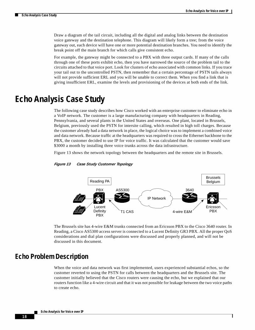
Figure 13 shows the network topology between the headquarters and the remote site in Brusse
Figure 13 Case Study Customer Topology
The Brussels site has 4-wire E&M trunks connected from an Ericsson PBX to the Cisco 3640 routReading, a Cisco AS5300 access server is connected to a Lucent Definity GR3 PBX. All the properconsiderations and dial plan configurations were discussed and properly planned, and will not bdiscussed in this document.
Echo Problem DescriptionWhen the voice and data network was first implemented, users experienced substantial echos, customer reverted to using the PSTN for calls between the headquarters and the Brussels site. customer initially believed that the Cisco routers were causing the echo, but we explained that orouters function like a 4-wire circuit and that it was not possible for leakage between the two voice pto create echo.
Reading PA
IP Network
PBX AS5300 3640
T1 CAS 4-wire E&MLucentDefinity
PBX
EricssonPBX
BrusselsBelgium
18Echo Analysis for Voice over IP
Echo Analysis for Voice over IPEcho Analysis Case Study
source
ERLo theould they.
ire.mer's
d but
ys, and
y
e testtomermer'sromthe clear.
theecho.3640nd
After testing calls between headquarters and Brussels, we noticed large amounts of echo anddetermined that the echo was being heard only on the headquarters end of the calls; therefore, theof the echo was in the Brussels tail circuit—between the Cisco 3640 router and the telephone inBrussels.
Initially, we thought this might be a case of loud echo, which means an echo caused by insufficientin the tail circuit. We ruled out the possibility of a long echo—an echo delay longer than the echcanceler's coverage. The Cisco 3640 had echo cancelers active on the Brussels tail circuit, andBrussels tail was connected only to the PBX. Long echo was not a possibility because the PBX wnot cause a delay long enough to cause long echo. If calls from headquarters were dropping offBrussels PBX or being routed to a third destination, long echo could then have been a possibilit
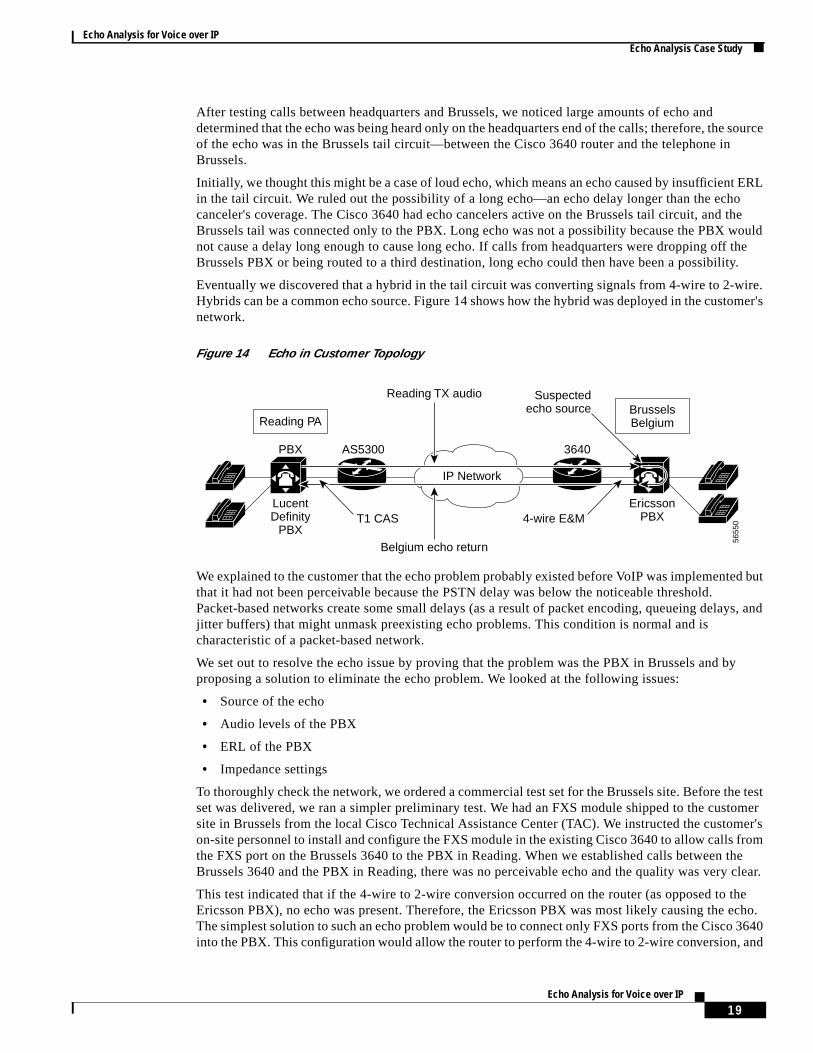
Eventually we discovered that a hybrid in the tail circuit was converting signals from 4-wire to 2-wHybrids can be a common echo source. Figure 14 shows how the hybrid was deployed in the custonetwork.
Figure 14 Echo in Customer Topology
We explained to the customer that the echo problem probably existed before VoIP was implementethat it had not been perceivable because the PSTN delay was below the noticeable threshold.Packet-based networks create some small delays (as a result of packet encoding, queueing delajitter buffers) that might unmask preexisting echo problems. This condition is normal and ischaracteristic of a packet-based network.
We set out to resolve the echo issue by proving that the problem was the PBX in Brussels and bproposing a solution to eliminate the echo problem. We looked at the following issues:
• Source of the echo
• Audio levels of the PBX
• ERL of the PBX
• Impedance settings
To thoroughly check the network, we ordered a commercial test set for the Brussels site. Before thset was delivered, we ran a simpler preliminary test. We had an FXS module shipped to the cussite in Brussels from the local Cisco Technical Assistance Center (TAC). We instructed the custoon-site personnel to install and configure the FXS module in the existing Cisco 3640 to allow calls fthe FXS port on the Brussels 3640 to the PBX in Reading. When we established calls between Brussels 3640 and the PBX in Reading, there was no perceivable echo and the quality was very
This test indicated that if the 4-wire to 2-wire conversion occurred on the router (as opposed to Ericsson PBX), no echo was present. Therefore, the Ericsson PBX was most likely causing the The simplest solution to such an echo problem would be to connect only FXS ports from the Ciscointo the PBX. This configuration would allow the router to perform the 4-wire to 2-wire conversion, a
Reading PA
IP Network
Reading TX audio
Belgium echo return
PBX AS5300 3640
T1 CAS 4-wire E&MLucentDefinity
PBX
EricssonPBX
BrusselsBelgium
5655
0
Suspectedecho source
19Echo Analysis for Voice over IP
Echo Analysis for Voice over IPEcho Analysis Case Study
ays FXS
on
00
ad thewed4-Hzvoice
s.isco
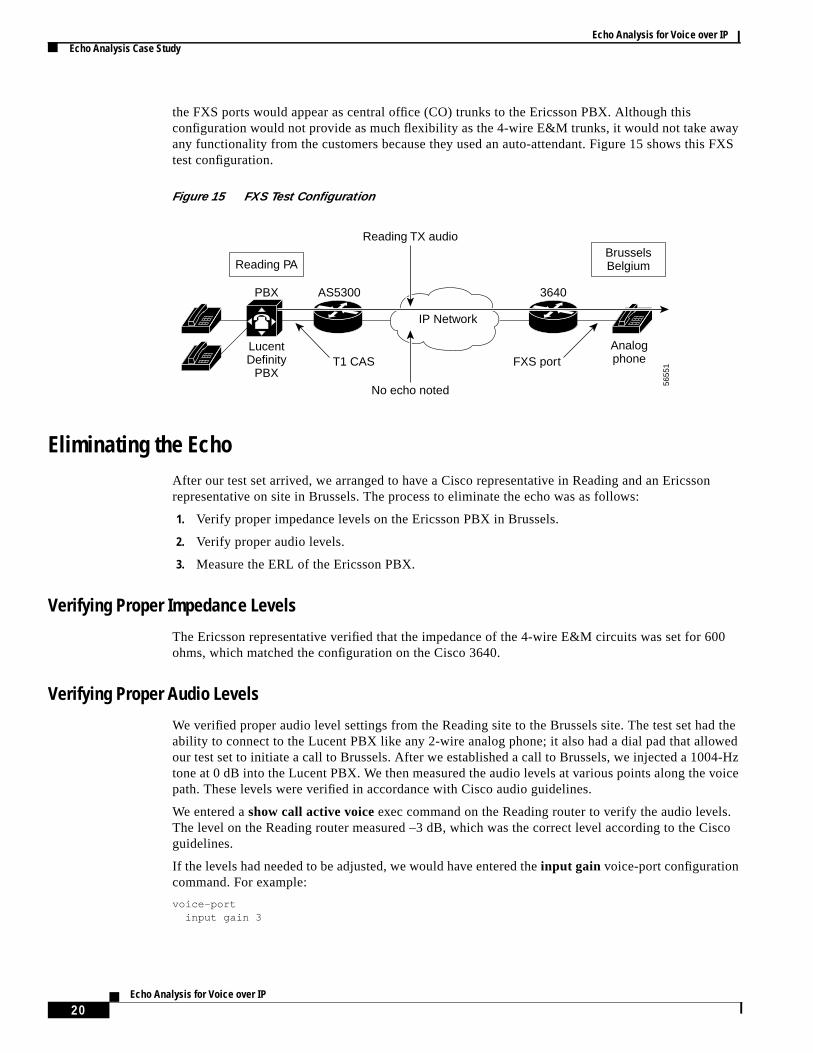
the FXS ports would appear as central office (CO) trunks to the Ericsson PBX. Although thisconfiguration would not provide as much flexibility as the 4-wire E&M trunks, it would not take awany functionality from the customers because they used an auto-attendant. Figure 15 shows thitest configuration.
Figure 15 FXS Test Configuration
Eliminating the EchoAfter our test set arrived, we arranged to have a Cisco representative in Reading and an Ericssrepresentative on site in Brussels. The process to eliminate the echo was as follows:
1. Verify proper impedance levels on the Ericsson PBX in Brussels.
2. Verify proper audio levels.
3. Measure the ERL of the Ericsson PBX.
Verifying Proper Impedance Levels
The Ericsson representative verified that the impedance of the 4-wire E&M circuits was set for 6ohms, which matched the configuration on the Cisco 3640.
Verifying Proper Audio Levels
We verified proper audio level settings from the Reading site to the Brussels site. The test set hability to connect to the Lucent PBX like any 2-wire analog phone; it also had a dial pad that alloour test set to initiate a call to Brussels. After we established a call to Brussels, we injected a 100tone at 0 dB into the Lucent PBX. We then measured the audio levels at various points along thepath. These levels were verified in accordance with Cisco audio guidelines.
We entered ashow call active voice exec command on the Reading router to verify the audio levelThe level on the Reading router measured –3 dB, which was the correct level according to the Cguidelines.
If the levels had needed to be adjusted, we would have entered theinput gain voice-port configurationcommand. For example:
voice-portinput gain 3
Reading PA
IP Network
Reading TX audio
No echo noted
PBX AS5300 3640
T1 CAS FXS portLucentDefinity
PBX
Analogphone
BrusselsBelgium
5655
1
20Echo Analysis for Voice over IP
Echo Analysis for Voice over IPEcho Analysis Case Study
take
ing2 dBepict
d raisee echo. You
This command increases the level into the VoIP network by 3 dB. For these input gain changes toeffect, you need to hang up and reestablish the call.
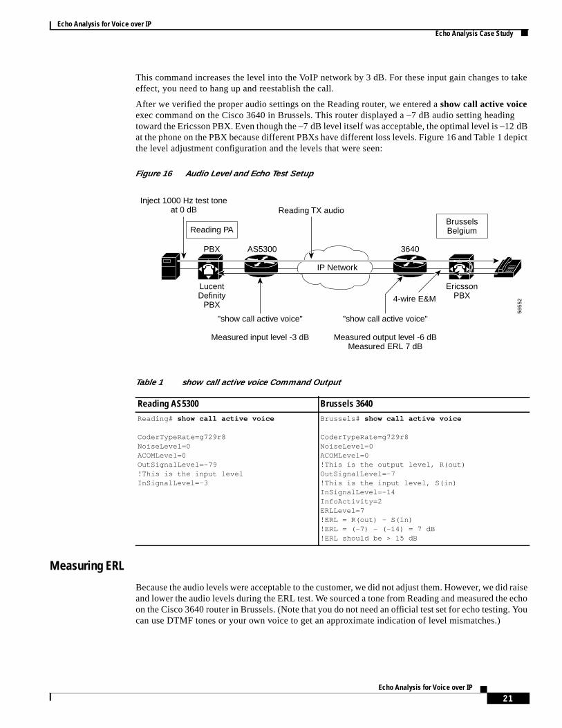
After we verified the proper audio settings on the Reading router, we entered ashow call active voiceexec command on the Cisco 3640 in Brussels. This router displayed a –7 dB audio setting headtoward the Ericsson PBX. Even though the –7 dB level itself was acceptable, the optimal level is –1at the phone on the PBX because different PBXs have different loss levels. Figure 16 and Table 1 dthe level adjustment configuration and the levels that were seen:
Figure 16 Audio Level and Echo Test Setup
Measuring ERL
Because the audio levels were acceptable to the customer, we did not adjust them. However, we diand lower the audio levels during the ERL test. We sourced a tone from Reading and measured thon the Cisco 3640 router in Brussels. (Note that you do not need an official test set for echo testingcan use DTMF tones or your own voice to get an approximate indication of level mismatches.)
Reading PA
IP Network
Reading TX audio
"show call active voice"
Measured input level -3 dB
PBX AS5300 3640
4-wire E&M
LucentDefinity
PBX
EricssonPBX
BrusselsBelgium
5655
2
Inject 1000 Hz test toneat 0 dB
"show call active voice"
Measured output level -6 dBMeasured ERL 7 dB
Table 1 show call active voice Command Output
Reading AS5300 Brussels 3640Reading# show call active voice
CoderTypeRate=g729r8NoiseLevel=0ACOMLevel=0OutSignalLevel=-79!This is the input levelInSignalLevel=-3
Brussels# show call active voice
CoderTypeRate=g729r8NoiseLevel=0ACOMLevel=0!This is the output level, R(out)OutSignalLevel=-7!This is the input level, S(in)InSignalLevel=-14InfoActivity=2ERLLevel=7!ERL = R(out) - S(in)!ERL = (-7) - (-14) = 7 dB!ERL should be > 15 dB
21Echo Analysis for Voice over IP
Echo Analysis for Voice over IPEcho Analysis Case Study
ingdB,only
aswithup
te the
We applied the same 1004-Hz tone at 0 dB to the Reading PBX and then we again entered theshow callactive voiceexec command to display the ERL level. The ERL represents the level of the echo comout of the PBX in relation to the signal into the PBX. Notice that in Table 1 the ERL level is –14which means that, in relation to the signal going into the PBX, the echo is coming back at a level7 dB less than what was going in.
The International Telecommunication Union Telecommunication Standardization Sector (ITU-T)recommendation G.131 states that the ERL of a PBX should be greater than 15 dB. The ERL wsubstantially higher than an echo canceler can effectively nullify; therefore, the echo problem wasthe Brussels PBX. To further verify the problem location, we adjusted the audio level into the PBXand down. When we adjusted the audio level, the ERL remained constant.
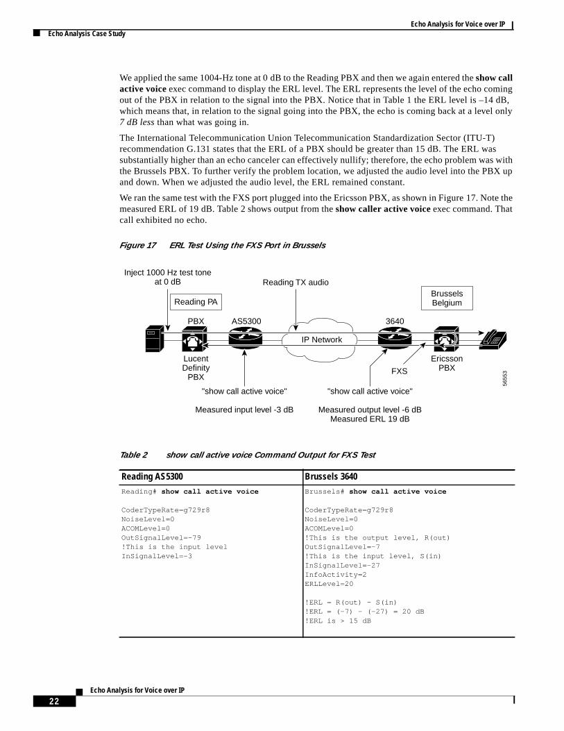
We ran the same test with the FXS port plugged into the Ericsson PBX, as shown in Figure 17. Nomeasured ERL of 19 dB. Table 2 shows output from theshow caller active voiceexec command. Thatcall exhibited no echo.
Figure 17 ERL Test Using the FXS Port in Brussels
Reading PA
IP Network
Reading TX audio
"show call active voice"
Measured input level -3 dB
PBX AS5300 3640
FXS
LucentDefinity
PBX
EricssonPBX
BrusselsBelgium
5655
3
Inject 1000 Hz test toneat 0 dB
"show call active voice"
Measured output level -6 dBMeasured ERL 19 dB
Table 2 show call active voice Command Output for FXS Test
Reading AS5300 Brussels 3640Reading# show call active voice
CoderTypeRate=g729r8NoiseLevel=0ACOMLevel=0OutSignalLevel=-79!This is the input levelInSignalLevel=-3
Brussels# show call active voice
CoderTypeRate=g729r8NoiseLevel=0ACOMLevel=0!This is the output level, R(out)OutSignalLevel=-7!This is the input level, S(in)InSignalLevel=-27InfoActivity=2ERLLevel=20
!ERL = R(out) - S(in)!ERL = (-7) - (-27) = 20 dB!ERL is > 15 dB
22Echo Analysis for Voice over IP
Echo Analysis for Voice over IPRelated Documents
nd of3640ll
-based
ucharege ofhisist
Case Study SummaryThe customer was satisfied with our testing results and decided to use our suggested workarouusing FXS ports, which appeared as CO trunks to the Brussels PBX, out of the Brussels Cisco router. This solution reduced some of the inward dialing flexibility of the network, but because ainbound calls were handled by an auto-attendant, no functionality was lost.
This case study illustrates the importance of educating customers about proper expectations ofpacket-based networks. Specifically, you should stress that the normal characteristics of packetnetworks may unmask preexisting problems in the TDM-based voice infrastructures.
This particular kind of echo problem—where the echo is PBX-based—is the easiest to solve. It is mmore difficult to solve a case where the tail circuit is the PSTN and calls only to some locations being affected. Not only are such cases difficult to troubleshoot, but they also present the challenyour convincing the customer that the problem is in the PSTN, not the VoIP network. In reality, ttype of echo problem is not related just to VoIP. It is essentially media-independent, and can exwherever added delays in the network might exist.
Related Documents• Cisco IOS Voice, Video and Fax Configuration Guide
• Shenoi, K.Digital Signal Processing in Telecommunications. Prentice Hall PTR; 1995
• Voice over IP Fundamentals, Cisco Press, 2000
23Echo Analysis for Voice over IP

Echo Analysis for Voice over IPRelated Documents
24Echo Analysis for Voice over IP