ECH630-ECH749, CH735, CH26, CH745 Service Manual · ECH630-ECH749, CH735, CH26, CH745 Service...
124
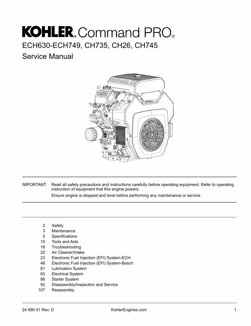
ECH630-ECH749, CH735, CH26, CH745 Service Manual KohlerEngines.com 1 24 690 01 Rev. D 2 Safety 3 Maintenance 5 Specifications 15 Tools and Aids 18 Troubleshooting 22 Air Cleaner/Intake 23 Electronic Fuel Injection (EFI) System-ECH 48 Electronic Fuel Injection (EFI) System-Bosch 81 Lubrication System 83 Electrical System 88 Starter System 92 Disassembly/Inspection and Service 107 Reassembly IMPORTANT: Read all safety precautions and instructions carefully before operating equipment. Refer to operating instruction of equipment that this engine powers. Ensure engine is stopped and level before performing any maintenance or service.
Transcript of ECH630-ECH749, CH735, CH26, CH745 Service Manual · ECH630-ECH749, CH735, CH26, CH745 Service...
ECH630-ECH749, CH735, CH26, CH745Service Manual
KohlerEngines.com 124 690 01 Rev. D
2 Safety3 Maintenance5 Specifications
15 Tools and Aids18 Troubleshooting22 Air Cleaner/Intake23 Electronic Fuel Injection (EFI) System-ECH48 Electronic Fuel Injection (EFI) System-Bosch81 Lubrication System83 Electrical System88 Starter System92 Disassembly/Inspection and Service
107 Reassembly
IMPORTANT: Read all safety precautions and instructions carefully before operating equipment. Refer to operating instruction of equipment that this engine powers.
Ensure engine is stopped and level before performing any maintenance or service.
Safety
2 24 690 01 Rev. DKohlerEngines.com
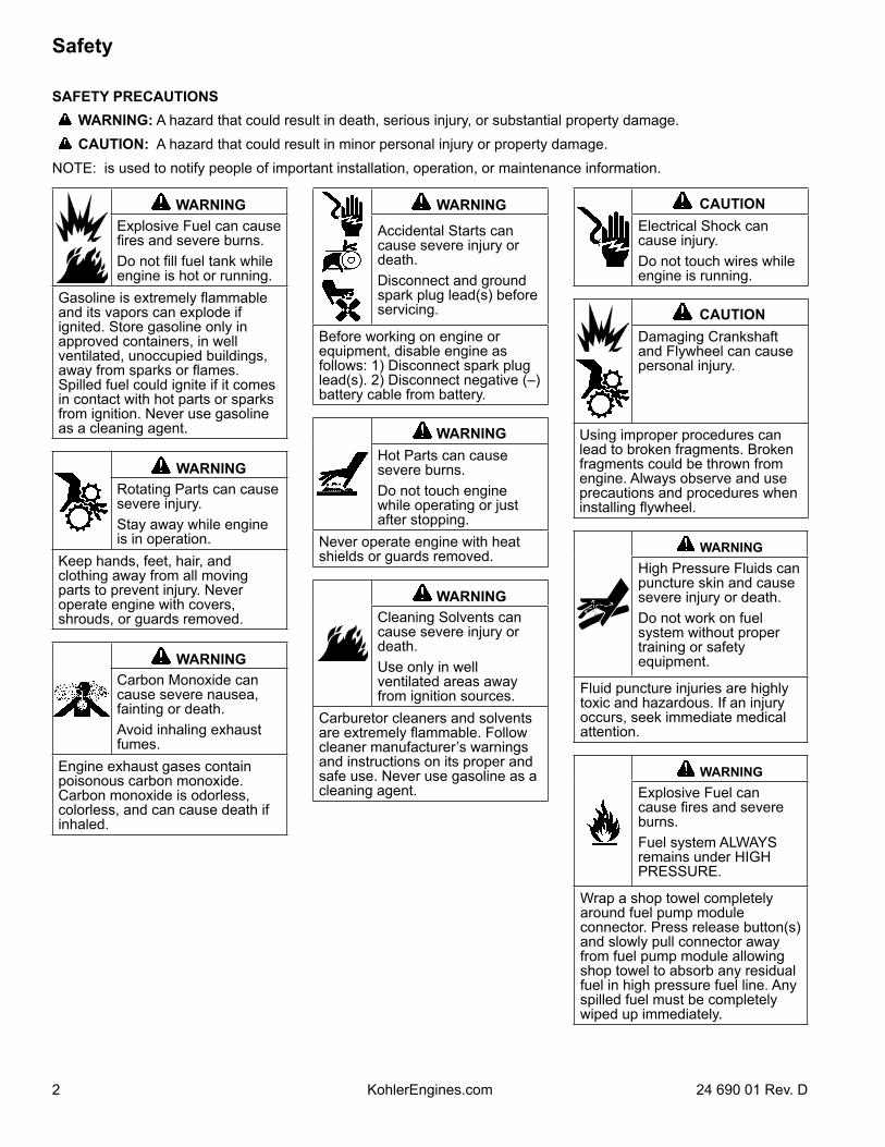
SAFETY PRECAUTIONS WARNING: A hazard that could result in death, serious injury, or substantial property damage. CAUTION: A hazard that could result in minor personal injury or property damage.NOTE: is used to notify people of important installation, operation, or maintenance information.
WARNINGExplosive Fuel can cause fires and severe burns.Do not fill fuel tank while engine is hot or running.
Gasoline is extremely flammable and its vapors can explode if ignited. Store gasoline only in approved containers, in well ventilated, unoccupied buildings, away from sparks or flames. Spilled fuel could ignite if it comes in contact with hot parts or sparks from ignition. Never use gasoline as a cleaning agent.
WARNINGRotating Parts can cause severe injury.Stay away while engine is in operation.
Keep hands, feet, hair, and clothing away from all moving parts to prevent injury. Never operate engine with covers, shrouds, or guards removed.
WARNINGCarbon Monoxide can cause severe nausea, fainting or death.Avoid inhaling exhaust fumes.
Engine exhaust gases contain poisonous carbon monoxide. Carbon monoxide is odorless, colorless, and can cause death if inhaled.
WARNING
Accidental Starts can cause severe injury or death.Disconnect and ground spark plug lead(s) before servicing.
Before working on engine or equipment, disable engine as follows: 1) Disconnect spark plug lead(s). 2) Disconnect negative (–) battery cable from battery.
WARNINGHot Parts can cause severe burns.Do not touch engine while operating or just after stopping.
Never operate engine with heat shields or guards removed.
WARNINGCleaning Solvents can cause severe injury or death.Use only in well ventilated areas away from ignition sources.
Carburetor cleaners and solvents are extremely flammable. Follow cleaner manufacturer’s warnings and instructions on its proper and safe use. Never use gasoline as a cleaning agent.
CAUTIONElectrical Shock can cause injury.Do not touch wires while engine is running.
CAUTIONDamaging Crankshaft and Flywheel can cause personal injury.
Using improper procedures can lead to broken fragments. Broken fragments could be thrown from engine. Always observe and use precautions and procedures when installing flywheel.
WARNINGHigh Pressure Fluids can puncture skin and cause severe injury or death.Do not work on fuel system without proper training or safety equipment.
Fluid puncture injuries are highly toxic and hazardous. If an injury occurs, seek immediate medical attention.
WARNINGExplosive Fuel can cause fires and severe burns.Fuel system ALWAYS remains under HIGH PRESSURE.
Wrap a shop towel completely around fuel pump module connector. Press release button(s) and slowly pull connector away from fuel pump module allowing shop towel to absorb any residual fuel in high pressure fuel line. Any spilled fuel must be completely wiped up immediately.
Maintenance
324 690 01 Rev. D KohlerEngines.com
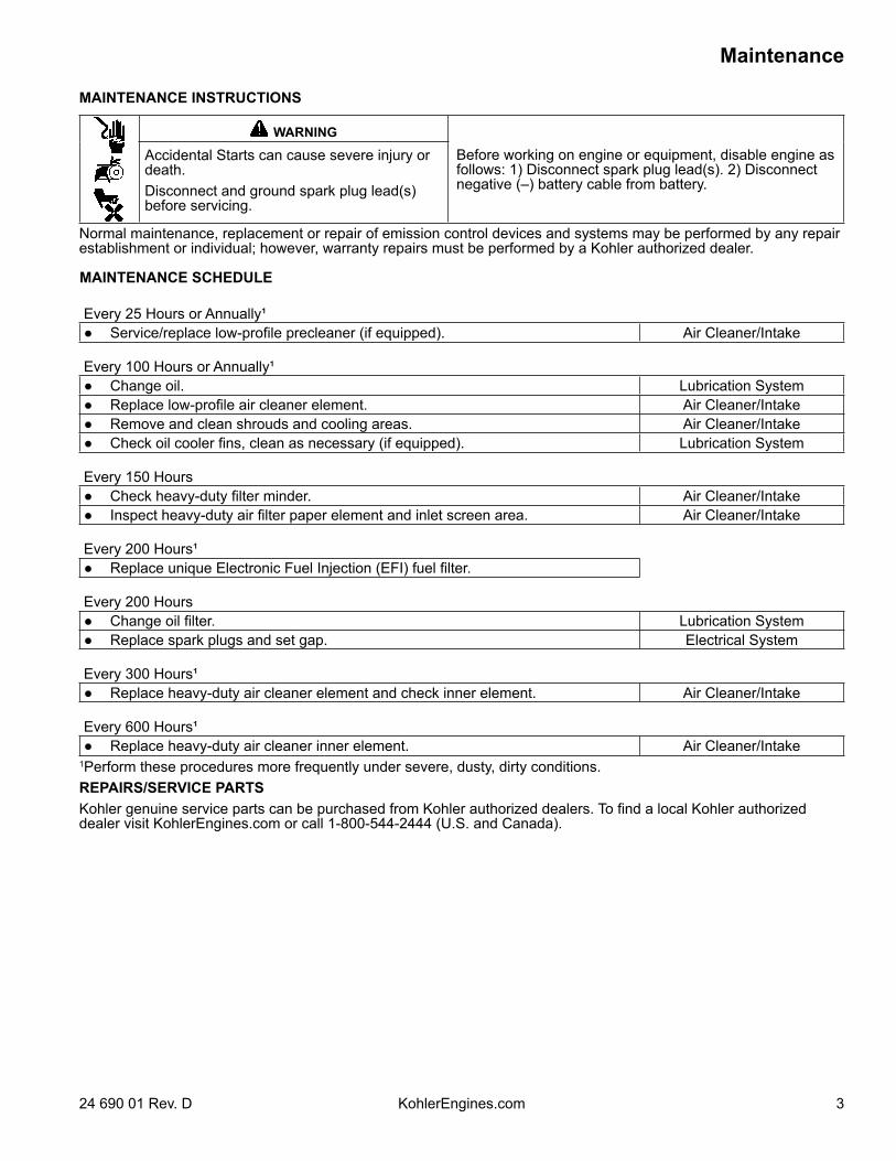
MAINTENANCE INSTRUCTIONS
WARNING
Before working on engine or equipment, disable engine as follows: 1) Disconnect spark plug lead(s). 2) Disconnect negative (–) battery cable from battery.
Accidental Starts can cause severe injury or death.Disconnect and ground spark plug lead(s) before servicing.
Normal maintenance, replacement or repair of emission control devices and systems may be performed by any repair establishment or individual; however, warranty repairs must be performed by a Kohler authorized dealer.
MAINTENANCE SCHEDULE
Every 25 Hours or Annually¹ Service/replace low-profile precleaner (if equipped). Air Cleaner/Intake
Every 100 Hours or Annually¹ Change oil. Lubrication System Replace low-profile air cleaner element. Air Cleaner/Intake Remove and clean shrouds and cooling areas. Air Cleaner/Intake Check oil cooler fins, clean as necessary (if equipped). Lubrication System
Every 150 Hours Check heavy-duty filter minder. Air Cleaner/Intake Inspect heavy-duty air filter paper element and inlet screen area. Air Cleaner/Intake
Every 200 Hours¹ Replace unique Electronic Fuel Injection (EFI) fuel filter.
Every 200 Hours Change oil filter. Lubrication System Replace spark plugs and set gap. Electrical System
Every 300 Hours¹ Replace heavy-duty air cleaner element and check inner element. Air Cleaner/Intake
Every 600 Hours¹ Replace heavy-duty air cleaner inner element. Air Cleaner/Intake
1Perform these procedures more frequently under severe, dusty, dirty conditions.REPAIRS/SERVICE PARTSKohler genuine service parts can be purchased from Kohler authorized dealers. To find a local Kohler authorized dealer visit KohlerEngines.com or call 1-800-544-2444 (U.S. and Canada).
Maintenance
4 24 690 01 Rev. DKohlerEngines.com
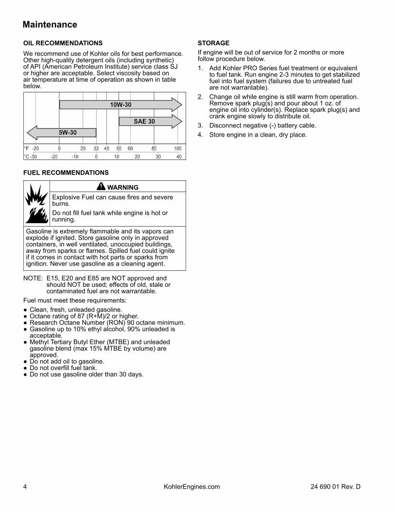
OIL RECOMMENDATIONSWe recommend use of Kohler oils for best performance. Other high-quality detergent oils (including synthetic) of API (American Petroleum Institute) service class SJ or higher are acceptable. Select viscosity based on air temperature at time of operation as shown in table below.
FUEL RECOMMENDATIONS
WARNINGExplosive Fuel can cause fires and severe burns.Do not fill fuel tank while engine is hot or running.
Gasoline is extremely flammable and its vapors can explode if ignited. Store gasoline only in approved containers, in well ventilated, unoccupied buildings, away from sparks or flames. Spilled fuel could ignite if it comes in contact with hot parts or sparks from ignition. Never use gasoline as a cleaning agent.
NOTE: E15, E20 and E85 are NOT approved and should NOT be used; effects of old, stale or contaminated fuel are not warrantable.
Fuel must meet these requirements: Clean, fresh, unleaded gasoline. Octane rating of 87 (R+M)/2 or higher. Research Octane Number (RON) 90 octane minimum. Gasoline up to 10% ethyl alcohol, 90% unleaded is
acceptable. Methyl Tertiary Butyl Ether (MTBE) and unleaded
gasoline blend (max 15% MTBE by volume) are approved.
Do not add oil to gasoline. Do not overfill fuel tank. Do not use gasoline older than 30 days.
STORAGEIf engine will be out of service for 2 months or more follow procedure below.1. Add Kohler PRO Series fuel treatment or equivalent
to fuel tank. Run engine 2-3 minutes to get stabilized fuel into fuel system (failures due to untreated fuel are not warrantable).
2. Change oil while engine is still warm from operation. Remove spark plug(s) and pour about 1 oz. of engine oil into cylinder(s). Replace spark plug(s) and crank engine slowly to distribute oil.
3. Disconnect negative (-) battery cable.4. Store engine in a clean, dry place.
Specifications
524 690 01 Rev. D KohlerEngines.com
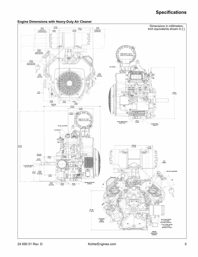
Dimensions in millimeters. Inch equivalents shown in [ ].
424.29(16.704) 304.72
(11.997)277.30(10.917)
135.00(5.315)
Air Filter Rain Cap Removal
88.20(3.473)
130.00(5.118)
Air Filter CoverAssembly Removal
230.20(9.063)
Safety Air FilterElement Removal
342.52(13.485)
Primary Air FilterElement Removal
19.22(0.757)
Spark Plug
15.70(0.618)
142.89(5.626)
92.10(3.626)
184.20(7.252)
17.53(0.690)
Spark Plug
MountingHole “A”
Engine
LIFT STRAP
2X OIL DRAIN PLUG3/8 NPT (IN.)
89.00(3.504)
MOUNTINGHOLE “A”
432.61(17.032)
471.44(18.560)
210.40(8.284)
52.40(20.063)
OIL FILL LOCATION
OIL DIPSTICK
622.63(24.513)
1/4 IN. SQ. KEYWAY
85.50(3.366)
28.56Ø(1.125)
7/16-20 UNF 2B (IN.)38.10 (1.500)
155.58(6.125)
152.08(5.987)
OIL FILTER97.38
(3.834)
52.75(2.077)
OIL FILTER104.00(4.094)
89.00(3.504)
ENGINE MOUNTING SURFACE
301.59(11.874)
SOLENOID SHIFT
STARTER
45˚ 45˚
ENGINE MOUNTING
SURFACE
7/16-14 UNC 2B (IN.)21.0 (0.827)
Ø196.85 (7.75) B.C.
3/8-16 UNC 2B (IN.)17.0 (0.669)
Ø142.88 (5.625) B.C.
30˚
OIL FILL LOCATION
LIFTSTRAP
51.20(2.016)
286.49(11.279)
30˚ 30˚
30˚
Engine Dimensions with Heavy-Duty Air Cleaner
Specifications
6 24 690 01 Rev. DKohlerEngines.com
FUEL PUMP
370.05(14.569)
30.00(1.181)
SPARK PLUG
3.05(0.120)
OIL FILL
OIL FILL
1/4 IN. SQ. KEYWAY
101.38(3.992)
8550(3.366)
KEYWAY
7/16-20 UNF 28 IN.38.10 (1.500)
155.58(6.125)
152.08(5.987)
OIL FILTER
ENGINE MOUNTING SURFACE
MOUNTING SURFACE
4.00 (0.157)PILOT
52.75(2.077)
OIL FILTER
100.00(3.937)
51.00(2.008)
89.00(3.504)
12.19(0.480)
RECTIFIERREGULATOR
OIL DRAIN PLUG3/8 IN. NPT
MOUNTINGHOLE “A”
PILOT 177.800 (7.000)OPTIONAL PILOT 146.050 (5.750)
ENGINE MTG SURFACE
SOLENOID SHIFT
STARTER
MOUNTING HOLE “A”
M8 X 1.2520.5 DEEP2 HOLESMUFFLER MTG BOSSES
308.17(12.133)
M8 X 1.254 STUDS
283.58(11.164)
50.00(1.969)EXHAUSTPORT #1
50.00(1.969)
EXHAUST PORT #2
LIFT STRAP75.35
(2.966)65.00(2.559)
122.10(4.807)
173.68(6.838)
30˚
334.78(13.180)
50.00 (1.969) SPARK PLUG
32.00 (1.260) EXHAUST PORT #2
12.00 (0.472) EXHAUST PORT #1
OIL DIPSTICK
432.61(17.032)
ENGINE MOUNTING SURFACE67.50 (2.657) MUFFLER MOUNTING
BOSSES
51.00(2.008)
89.00(3.504)
OIL DRAIN PLUG3/8 IN. NPT
12.19(0.480)
426.44(16.789)
302.63(11.915)
12.15(0.478)
60.00(2.362)
AIR CLEANERCOVER REMOVAL
17.07(0.672)
SPARK PLUG
FUEL FILTER
CRANKSHAFT
15.70(0.618)
OIL FILTERREMOVAL
142.89(5.626)
92.10(3.626)
184.20(7.252)
MOUNTING HOLES
ENGINE
MOUNTING HOLE “A”
463.36(18.242)
17.53(0.690)
SPARK PLUG
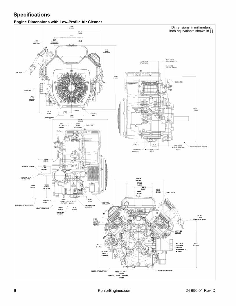
Engine Dimensions with Low-Profile Air CleanerDimensions in millimeters.
Inch equivalents shown in [ ].
Specifications
724 690 01 Rev. D KohlerEngines.com
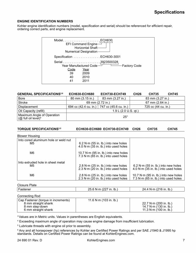
ENGINE IDENTIFICATION NUMBERSKohler engine identification numbers (model, specification and serial) should be referenced for efficient repair, ordering correct parts, and engine replacement.
Model . . . . . . . . . . . . . . . . . . . . . ECH630EFI Command Engine
Horizontal ShaftNumerical Designation
Specification . . . . . . . . . . . . . . . ECH630-3001Serial . . . . . . . . . . . . . . . . . . . . . 3923500328
Year Manufactured Code Factory Code Code Year 39 2009 40 2010 41 2011
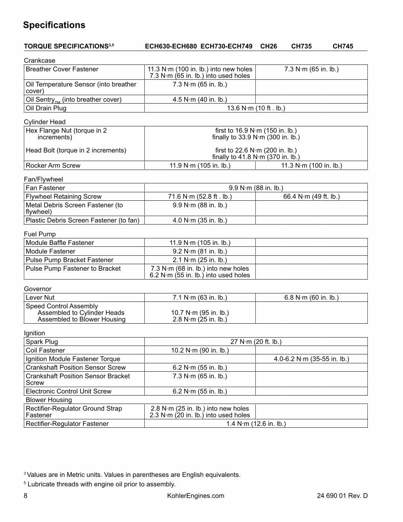
GENERAL SPECIFICATIONS3,6 ECH630-ECH680 ECH730-ECH749 CH26 CH735 CH745Bore 80 mm (3.15 in.) 83 mm (3.27 in.) 83 mm (3.27 in.)Stroke 69 mm (2.72 in.) 67 mm (2.64 in.)Displacement 694 cc (42.4 cu. in.) 747 cc (45.6 cu. in.) 725 cc (44 cu. in.)Oil Capacity (refill) 1.9 L (2.0 U.S. qt.)Maximum Angle of Operation(@ full oil level)4 25°
TORQUE SPECIFICATIONS3,5 ECH630-ECH680 ECH730-ECH749 CH26 CH735 CH745
Blower HousingInto cored aluminum hole or weld nut M5
M6
Into extruded hole in sheet metal M5
M6
6.2 N·m (55 in. lb.) into new holes4.0 N·m (35 in. lb.) into used holes
10.7 N·m (95 in. lb.) into new holes7.3 N·m (65 in. lb.) into used holes
2.8 N·m (25 in. lb.) into new holes2.3 N·m (20 in. lb.) into used holes
2.8 N·m (25 in. lb.) into new holes2.3 N·m (20 in. lb.) into used holes
6.2 N·m (55 in. lb.) into new holes4.0 N·m (35 in. lb.) into used holes
10.7 N·m (95 in. lb.) into new holes7.3 N·m (65 in. lb.) into used holes
Closure PlateFastener 25.6 N·m (227 in. lb.) 24.4 N·m (216 in. lb.)
Connecting RodCap Fastener (torque in increments) 8 mm straight shank 8 mm step-down 6 mm straight shank
11.6 N·m (103 in. lb.)22.7 N·m (200 in. lb.)14.7 N·m (130 in. lb.)11.3 N·m (100 in. lb.)
3 Values are in Metric units. Values in parentheses are English equivalents. 4 Exceeding maximum angle of operation may cause engine damage from insufficient lubrication.5 Lubricate threads with engine oil prior to assembly.6 Any and all horsepower (hp) references by Kohler are Certified Power Ratings and per SAE J1940 & J1995 hp standards. Details on Certified Power Ratings can be found at KohlerEngines.com.
Specifications
8 24 690 01 Rev. DKohlerEngines.com
TORQUE SPECIFICATIONS3,5 ECH630-ECH680 ECH730-ECH749 CH26 CH735 CH745
CrankcaseBreather Cover Fastener 11.3 N·m (100 in. lb.) into new holes
7.3 N·m (65 in. lb.) into used holes7.3 N·m (65 in. lb.)
Oil Temperature Sensor (into breather cover)
7.3 N·m (65 in. lb.)
Oil SentryTM (into breather cover) 4.5 N·m (40 in. lb.)Oil Drain Plug 13.6 N·m (10 ft . lb.)
Cylinder HeadHex Flange Nut (torque in 2
increments)
Head Bolt (torque in 2 increments)
first to 16.9 N·m (150 in. lb.)finally to 33.9 N·m (300 in. lb.)
first to 22.6 N·m (200 in. lb.)finally to 41.8 N·m (370 in. lb.)
Rocker Arm Screw 11.9 N·m (105 in. lb.) 11.3 N·m (100 in. lb.)
Fan/FlywheelFan Fastener 9.9 N·m (88 in. lb.)Flywheel Retaining Screw 71.6 N·m (52.8 ft . lb.) 66.4 N·m (49 ft. lb.)Metal Debris Screen Fastener (to flywheel)
9.9 N·m (88 in. lb.)
Plastic Debris Screen Fastener (to fan) 4.0 N·m (35 in. lb.)
Fuel PumpModule Baffle Fastener 11.9 N·m (105 in. lb.)Module Fastener 9.2 N·m (81 in. lb.)Pulse Pump Bracket Fastener 2.1 N·m (25 in. lb.)Pulse Pump Fastener to Bracket 7.3 N·m (68 in. lb.) into new holes
6.2 N·m (55 in. lb.) into used holes
GovernorLever Nut 7.1 N·m (63 in. lb.) 6.8 N·m (60 in. lb.)Speed Control Assembly Assembled to Cylinder Heads Assembled to Blower Housing
10.7 N·m (95 in. lb.)2.8 N·m (25 in. lb.)
IgnitionSpark Plug 27 N·m (20 ft. lb.)Coil Fastener 10.2 N·m (90 in. lb.)Ignition Module Fastener Torque 4.0-6.2 N·m (35-55 in. lb.)Crankshaft Position Sensor Screw 6.2 N·m (55 in. lb.)Crankshaft Position Sensor Bracket Screw
7.3 N·m (65 in. lb.)
Electronic Control Unit Screw 6.2 N·m (55 in. lb.)Blower HousingRectifier-Regulator Ground Strap Fastener
2.8 N·m (25 in. lb.) into new holes2.3 N·m (20 in. lb.) into used holes
Rectifier-Regulator Fastener 1.4 N·m (12.6 in. lb.)
3 Values are in Metric units. Values in parentheses are English equivalents. 5 Lubricate threads with engine oil prior to assembly.
Specifications
924 690 01 Rev. D KohlerEngines.com
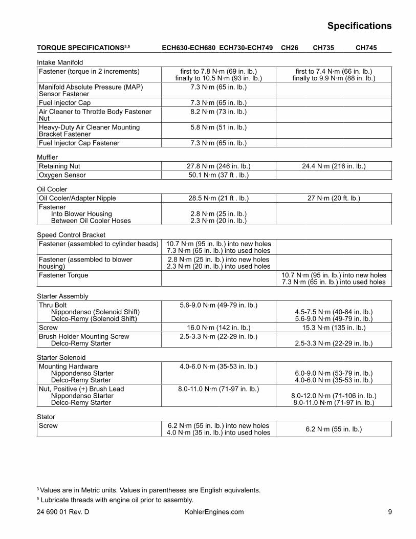
TORQUE SPECIFICATIONS3,5 ECH630-ECH680 ECH730-ECH749 CH26 CH735 CH745
Intake ManifoldFastener (torque in 2 increments) first to 7.8 N·m (69 in. lb.)
finally to 10.5 N·m (93 in. lb.)first to 7.4 N·m (66 in. lb.)
finally to 9.9 N·m (88 in. lb.)Manifold Absolute Pressure (MAP) Sensor Fastener
7.3 N·m (65 in. lb.)
Fuel Injector Cap 7.3 N·m (65 in. lb.)Air Cleaner to Throttle Body Fastener Nut
8.2 N·m (73 in. lb.)
Heavy-Duty Air Cleaner Mounting Bracket Fastener
5.8 N·m (51 in. lb.)
Fuel Injector Cap Fastener 7.3 N·m (65 in. lb.)
MufflerRetaining Nut 27.8 N·m (246 in. lb.) 24.4 N·m (216 in. lb.)Oxygen Sensor 50.1 N·m (37 ft . lb.)
Oil CoolerOil Cooler/Adapter Nipple 28.5 N·m (21 ft . lb.) 27 N·m (20 ft. lb.)Fastener Into Blower Housing Between Oil Cooler Hoses
2.8 N·m (25 in. lb.)2.3 N·m (20 in. lb.)
Speed Control BracketFastener (assembled to cylinder heads) 10.7 N·m (95 in. lb.) into new holes
7.3 N·m (65 in. lb.) into used holesFastener (assembled to blower housing)
2.8 N·m (25 in. lb.) into new holes2.3 N·m (20 in. lb.) into used holes
Fastener Torque 10.7 N·m (95 in. lb.) into new holes7.3 N·m (65 in. lb.) into used holes
Starter AssemblyThru Bolt Nippondenso (Solenoid Shift) Delco-Remy (Solenoid Shift)
5.6-9.0 N·m (49-79 in. lb.)4.5-7.5 N·m (40-84 in. lb.)5.6-9.0 N·m (49-79 in. lb.)
Screw 16.0 N·m (142 in. lb.) 15.3 N·m (135 in. lb.)Brush Holder Mounting Screw Delco-Remy Starter
2.5-3.3 N·m (22-29 in. lb.)2.5-3.3 N·m (22-29 in. lb.)
Starter SolenoidMounting Hardware Nippondenso Starter Delco-Remy Starter
4.0-6.0 N·m (35-53 in. lb.)6.0-9.0 N·m (53-79 in. lb.)4.0-6.0 N·m (35-53 in. lb.)
Nut, Positive (+) Brush Lead Nippondenso Starter Delco-Remy Starter
8.0-11.0 N·m (71-97 in. lb.)8.0-12.0 N·m (71-106 in. lb.)8.0-11.0 N·m (71-97 in. lb.)
StatorScrew 6.2 N·m (55 in. lb.) into new holes
4.0 N·m (35 in. lb.) into used holes 6.2 N·m (55 in. lb.)
3 Values are in Metric units. Values in parentheses are English equivalents. 5 Lubricate threads with engine oil prior to assembly.
Specifications
10 24 690 01 Rev. DKohlerEngines.com
TORQUE SPECIFICATIONS3,5 ECH630-ECH680 ECH730-ECH749 CH26 CH735 CH745
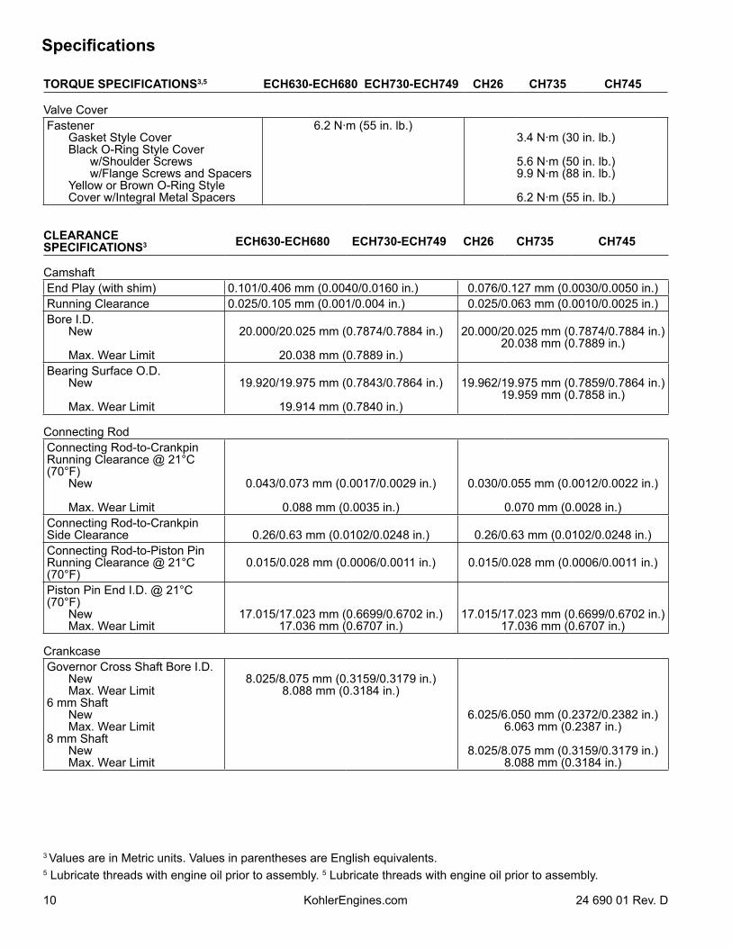
Valve CoverFastener Gasket Style Cover Black O-Ring Style Cover w/Shoulder Screws w/Flange Screws and Spacers Yellow or Brown O-Ring Style
Cover w/Integral Metal Spacers
6.2 N·m (55 in. lb.)3.4 N·m (30 in. lb.)
5.6 N·m (50 in. lb.)9.9 N·m (88 in. lb.)
6.2 N·m (55 in. lb.)
CLEARANCE SPECIFICATIONS3 ECH630-ECH680 ECH730-ECH749 CH26 CH735 CH745
CamshaftEnd Play (with shim) 0.101/0.406 mm (0.0040/0.0160 in.) 0.076/0.127 mm (0.0030/0.0050 in.)Running Clearance 0.025/0.105 mm (0.001/0.004 in.) 0.025/0.063 mm (0.0010/0.0025 in.)Bore I.D. New
Max. Wear Limit
20.000/20.025 mm (0.7874/0.7884 in.)
20.038 mm (0.7889 in.)
20.000/20.025 mm (0.7874/0.7884 in.)20.038 mm (0.7889 in.)
Bearing Surface O.D. New
Max. Wear Limit
19.920/19.975 mm (0.7843/0.7864 in.)
19.914 mm (0.7840 in.)
19.962/19.975 mm (0.7859/0.7864 in.)19.959 mm (0.7858 in.)
Connecting RodConnecting Rod-to-Crankpin Running Clearance @ 21°C (70°F) New
Max. Wear Limit
0.043/0.073 mm (0.0017/0.0029 in.)
0.088 mm (0.0035 in.)
0.030/0.055 mm (0.0012/0.0022 in.)
0.070 mm (0.0028 in.)Connecting Rod-to-Crankpin Side Clearance 0.26/0.63 mm (0.0102/0.0248 in.) 0.26/0.63 mm (0.0102/0.0248 in.)Connecting Rod-to-Piston Pin Running Clearance @ 21°C (70°F)
0.015/0.028 mm (0.0006/0.0011 in.) 0.015/0.028 mm (0.0006/0.0011 in.)
Piston Pin End I.D. @ 21°C (70°F) New Max. Wear Limit
17.015/17.023 mm (0.6699/0.6702 in.)17.036 mm (0.6707 in.)
17.015/17.023 mm (0.6699/0.6702 in.)17.036 mm (0.6707 in.)
CrankcaseGovernor Cross Shaft Bore I.D. New Max. Wear Limit6 mm Shaft New Max. Wear Limit8 mm Shaft New Max. Wear Limit
8.025/8.075 mm (0.3159/0.3179 in.)8.088 mm (0.3184 in.)
6.025/6.050 mm (0.2372/0.2382 in.)6.063 mm (0.2387 in.)
8.025/8.075 mm (0.3159/0.3179 in.)8.088 mm (0.3184 in.)
3 Values are in Metric units. Values in parentheses are English equivalents.5 Lubricate threads with engine oil prior to assembly. 5 Lubricate threads with engine oil prior to assembly.
Specifications
1124 690 01 Rev. D KohlerEngines.com
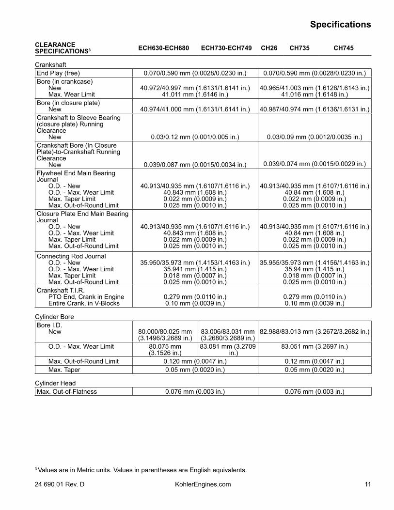
CLEARANCE SPECIFICATIONS3 ECH630-ECH680 ECH730-ECH749 CH26 CH735 CH745
CrankshaftEnd Play (free) 0.070/0.590 mm (0.0028/0.0230 in.) 0.070/0.590 mm (0.0028/0.0230 in.)Bore (in crankcase) New Max. Wear Limit
40.972/40.997 mm (1.6131/1.6141 in.)41.011 mm (1.6146 in.)
40.965/41.003 mm (1.6128/1.6143 in.)41.016 mm (1.6148 in.)
Bore (in closure plate) New 40.974/41.000 mm (1.6131/1.6141 in.) 40.987/40.974 mm (1.6136/1.6131 in.)Crankshaft to Sleeve Bearing (closure plate) Running Clearance New 0.03/0.12 mm (0.001/0.005 in.) 0.03/0.09 mm (0.0012/0.0035 in.)Crankshaft Bore (In Closure Plate)-to-Crankshaft Running Clearance New 0.039/0.087 mm (0.0015/0.0034 in.) 0.039/0.074 mm (0.0015/0.0029 in.)Flywheel End Main Bearing Journal O.D. - New O.D. - Max. Wear Limit Max. Taper Limit Max. Out-of-Round Limit
40.913/40.935 mm (1.6107/1.6116 in.)40.843 mm (1.608 in.)0.022 mm (0.0009 in.)0.025 mm (0.0010 in.)
40.913/40.935 mm (1.6107/1.6116 in.)40.84 mm (1.608 in.)0.022 mm (0.0009 in.)0.025 mm (0.0010 in.)
Closure Plate End Main Bearing Journal O.D. - New O.D. - Max. Wear Limit Max. Taper Limit Max. Out-of-Round Limit
40.913/40.935 mm (1.6107/1.6116 in.)40.843 mm (1.608 in.)0.022 mm (0.0009 in.)0.025 mm (0.0010 in.)
40.913/40.935 mm (1.6107/1.6116 in.)40.84 mm (1.608 in.)0.022 mm (0.0009 in.)0.025 mm (0.0010 in.)
Connecting Rod Journal O.D. - New O.D. - Max. Wear Limit Max. Taper Limit Max. Out-of-Round Limit
35.950/35.973 mm (1.4153/1.4163 in.)35.941 mm (1.415 in.)0.018 mm (0.0007 in.)0.025 mm (0.0010 in.)
35.955/35.973 mm (1.4156/1.4163 in.)35.94 mm (1.415 in.)0.018 mm (0.0007 in.)0.025 mm (0.0010 in.)
Crankshaft T.I.R. PTO End, Crank in Engine Entire Crank, in V-Blocks
0.279 mm (0.0110 in.)0.10 mm (0.0039 in.)
0.279 mm (0.0110 in.)0.10 mm (0.0039 in.)
Cylinder BoreBore I.D. New 80.000/80.025 mm
(3.1496/3.2689 in.)83.006/83.031 mm(3.2680/3.2689 in.)
82.988/83.013 mm (3.2672/3.2682 in.)
O.D. - Max. Wear Limit 80.075 mm(3.1526 in.)
83.081 mm (3.2709 in.)
83.051 mm (3.2697 in.)
Max. Out-of-Round Limit 0.120 mm (0.0047 in.) 0.12 mm (0.0047 in.) Max. Taper 0.05 mm (0.0020 in.) 0.05 mm (0.0020 in.)
Cylinder HeadMax. Out-of-Flatness 0.076 mm (0.003 in.) 0.076 mm (0.003 in.)
3 Values are in Metric units. Values in parentheses are English equivalents.
Specifications
12 24 690 01 Rev. DKohlerEngines.com
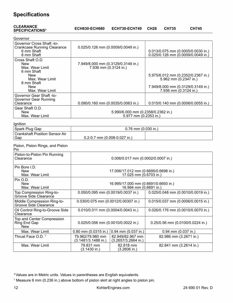
CLEARANCE SPECIFICATIONS3 ECH630-ECH680 ECH730-ECH749 CH26 CH735 CH745
GovernorGovernor Cross Shaft -to-Crankcase Running Clearance 6 mm Shaft 8 mm Shaft
0.025/0.126 mm (0.0009/0.0049 in.)0.013/0.075 mm (0.0005/0.0030 in.)0.025/0.126 mm (0.0009/0.0049 in.)
Cross Shaft O.D. New Max. Wear Limit 6 mm Shaft New Max. Wear Limit 8 mm Shaft New Max. Wear Limit
7.949/8.000 mm (0.3129/0.3149 in.)7.936 mm (0.3124 in.)
5.975/6.012 mm (0.2352/0.2367 in.)5.962 mm (0.2347 in.)
7.949/8.000 mm (0.3129/0.3149 in.)7.936 mm (0.3124 in.)
Governor Gear Shaft -to-Governor Gear Running Clearance 0.090/0.160 mm (0.0035/0.0063 in.) 0.015/0.140 mm (0.0006/0.0055 in.)Gear Shaft O.D. New Max. Wear Limit
5.990/6.000 mm (0.2358/0.2362 in.)5.977 mm (0.2353 in.)
IgnitionSpark Plug Gap 0.76 mm (0.030 in.)Crankshaft Position Sensor Air Gap 0.2-0.7 mm (0.008-0.027 in.)
Piston, Piston Rings, and Piston PinPiston-to-Piston Pin Running Clearance 0.006/0.017 mm (0.0002/0.0007 in.)
Pin Bore I.D. New Max. Wear Limit
17.006/17.012 mm (0.6695/0.6698 in.)17.025 mm (0.6703 in.)
Pin O.D. New Max. Wear Limit
16.995/17.000 mm (0.6691/0.6693 in.)16.994 mm (0.6691 in.)
Top Compression Ring-to-Groove Side Clearance
0.050/0.095 mm (0.0019/0.0037 in.) 0.025/0.048 mm (0.0010/0.0019 in.)
Middle Compression Ring-to-Groove Side Clearance
0.030/0.075 mm (0.0012/0.00307 in.) 0.015/0.037 mm (0.0006/0.0015 in.)
Oil Control Ring-to-Groove Side Clearance
0.010/0.011 mm (0.0004/0.0043 in.) 0.026/0.176 mm (0.0010/0.0070 in.)
Top and Center Compression Ring End Gap New
0.025/0.056 mm (0.0010/0.0022 in.) 0.25/0.56 mm (0.0100/0.0224 in.)
Max. Wear Limit 0.80 mm (0.0315 in.) 0.94 mm (0.037 in.) 0.94 mm (0.037 in.)Thrust Face O.D. 7 79.962/79.980 mm
(3.1481/3.1488 in.)82.949/82.967 mm(3.2657/3.2664 in.)
82.986 mm (3.2671 in.)
Max. Wear Limit 79.831 mm(3.1430 in.)
82.818 mm(3.2606 in.)
82.841 mm (3.2614 in.)
3 Values are in Metric units. Values in parentheses are English equivalents. 7 Measure 6 mm (0.236 in.) above bottom of piston skirt at right angles to piston pin.
Specifications
1324 690 01 Rev. D KohlerEngines.com
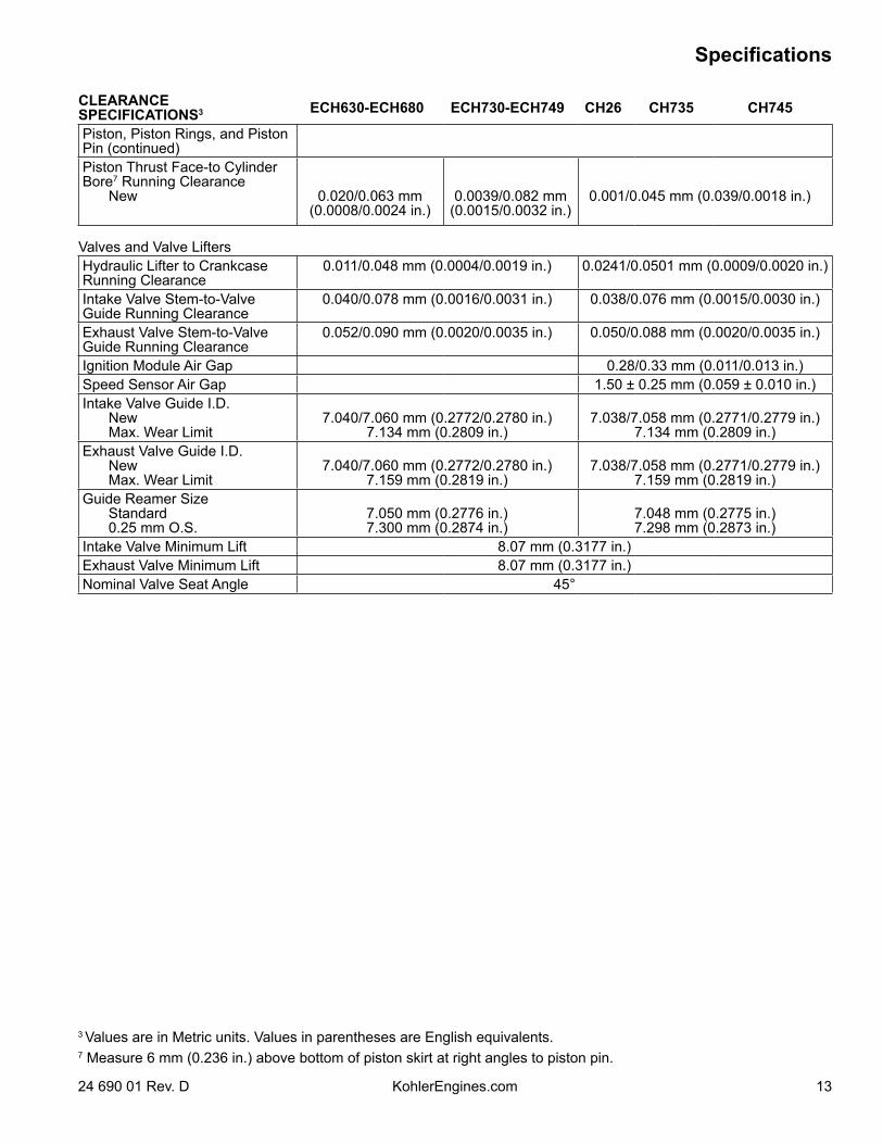
CLEARANCE SPECIFICATIONS3 ECH630-ECH680 ECH730-ECH749 CH26 CH735 CH745
Piston, Piston Rings, and Piston Pin (continued)Piston Thrust Face-to Cylinder Bore7 Running Clearance New 0.020/0.063 mm
(0.0008/0.0024 in.)0.0039/0.082 mm
(0.0015/0.0032 in.)0.001/0.045 mm (0.039/0.0018 in.)
Valves and Valve LiftersHydraulic Lifter to Crankcase Running Clearance
0.011/0.048 mm (0.0004/0.0019 in.) 0.0241/0.0501 mm (0.0009/0.0020 in.)
Intake Valve Stem-to-Valve Guide Running Clearance
0.040/0.078 mm (0.0016/0.0031 in.) 0.038/0.076 mm (0.0015/0.0030 in.)
Exhaust Valve Stem-to-Valve Guide Running Clearance
0.052/0.090 mm (0.0020/0.0035 in.) 0.050/0.088 mm (0.0020/0.0035 in.)
Ignition Module Air Gap 0.28/0.33 mm (0.011/0.013 in.)Speed Sensor Air Gap 1.50 ± 0.25 mm (0.059 ± 0.010 in.)Intake Valve Guide I.D. New Max. Wear Limit
7.040/7.060 mm (0.2772/0.2780 in.)7.134 mm (0.2809 in.)
7.038/7.058 mm (0.2771/0.2779 in.)7.134 mm (0.2809 in.)
Exhaust Valve Guide I.D. New Max. Wear Limit
7.040/7.060 mm (0.2772/0.2780 in.)7.159 mm (0.2819 in.)
7.038/7.058 mm (0.2771/0.2779 in.)7.159 mm (0.2819 in.)
Guide Reamer Size Standard 0.25 mm O.S.
7.050 mm (0.2776 in.)7.300 mm (0.2874 in.)
7.048 mm (0.2775 in.)7.298 mm (0.2873 in.)
Intake Valve Minimum Lift 8.07 mm (0.3177 in.)Exhaust Valve Minimum Lift 8.07 mm (0.3177 in.)Nominal Valve Seat Angle 45°
3 Values are in Metric units. Values in parentheses are English equivalents. 7 Measure 6 mm (0.236 in.) above bottom of piston skirt at right angles to piston pin.
Specifications
14 24 690 01 Rev. DKohlerEngines.com
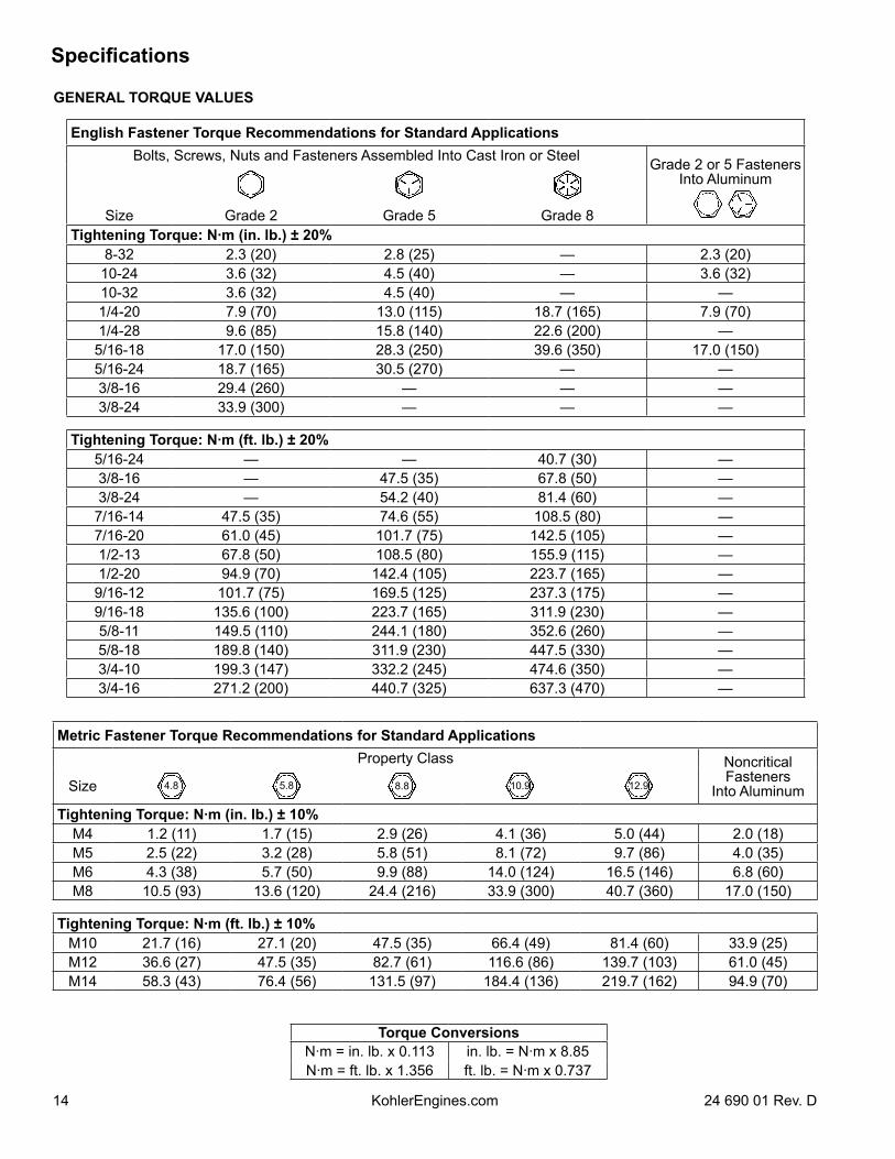
GENERAL TORQUE VALUES
Metric Fastener Torque Recommendations for Standard ApplicationsProperty Class Noncritical
Fasteners Into AluminumSize 4.8 5.8 8.8 10.9 12.9
Tightening Torque: N·m (in. lb.) ± 10%M4 1.2 (11) 1.7 (15) 2.9 (26) 4.1 (36) 5.0 (44) 2.0 (18)M5 2.5 (22) 3.2 (28) 5.8 (51) 8.1 (72) 9.7 (86) 4.0 (35)M6 4.3 (38) 5.7 (50) 9.9 (88) 14.0 (124) 16.5 (146) 6.8 (60)M8 10.5 (93) 13.6 (120) 24.4 (216) 33.9 (300) 40.7 (360) 17.0 (150)
Tightening Torque: N·m (ft. lb.) ± 10%M10 21.7 (16) 27.1 (20) 47.5 (35) 66.4 (49) 81.4 (60) 33.9 (25)M12 36.6 (27) 47.5 (35) 82.7 (61) 116.6 (86) 139.7 (103) 61.0 (45)M14 58.3 (43) 76.4 (56) 131.5 (97) 184.4 (136) 219.7 (162) 94.9 (70)
Torque ConversionsN·m = in. lb. x 0.113 in. lb. = N·m x 8.85N·m = ft. lb. x 1.356 ft. lb. = N·m x 0.737
English Fastener Torque Recommendations for Standard ApplicationsBolts, Screws, Nuts and Fasteners Assembled Into Cast Iron or Steel Grade 2 or 5 Fasteners
Into Aluminum
Size Grade 2 Grade 5 Grade 8Tightening Torque: N·m (in. lb.) ± 20%
8-32 2.3 (20) 2.8 (25) — 2.3 (20)10-24 3.6 (32) 4.5 (40) — 3.6 (32)10-32 3.6 (32) 4.5 (40) — —1/4-20 7.9 (70) 13.0 (115) 18.7 (165) 7.9 (70)1/4-28 9.6 (85) 15.8 (140) 22.6 (200) —5/16-18 17.0 (150) 28.3 (250) 39.6 (350) 17.0 (150)5/16-24 18.7 (165) 30.5 (270) — —3/8-16 29.4 (260) — — —3/8-24 33.9 (300) — — —
Tightening Torque: N·m (ft. lb.) ± 20%5/16-24 — — 40.7 (30) —3/8-16 — 47.5 (35) 67.8 (50) —3/8-24 — 54.2 (40) 81.4 (60) —
7/16-14 47.5 (35) 74.6 (55) 108.5 (80) —7/16-20 61.0 (45) 101.7 (75) 142.5 (105) —1/2-13 67.8 (50) 108.5 (80) 155.9 (115) —1/2-20 94.9 (70) 142.4 (105) 223.7 (165) —
9/16-12 101.7 (75) 169.5 (125) 237.3 (175) —9/16-18 135.6 (100) 223.7 (165) 311.9 (230) —5/8-11 149.5 (110) 244.1 (180) 352.6 (260) —5/8-18 189.8 (140) 311.9 (230) 447.5 (330) —3/4-10 199.3 (147) 332.2 (245) 474.6 (350) —3/4-16 271.2 (200) 440.7 (325) 637.3 (470) —
Tools and Aids
1524 690 01 Rev. D KohlerEngines.com
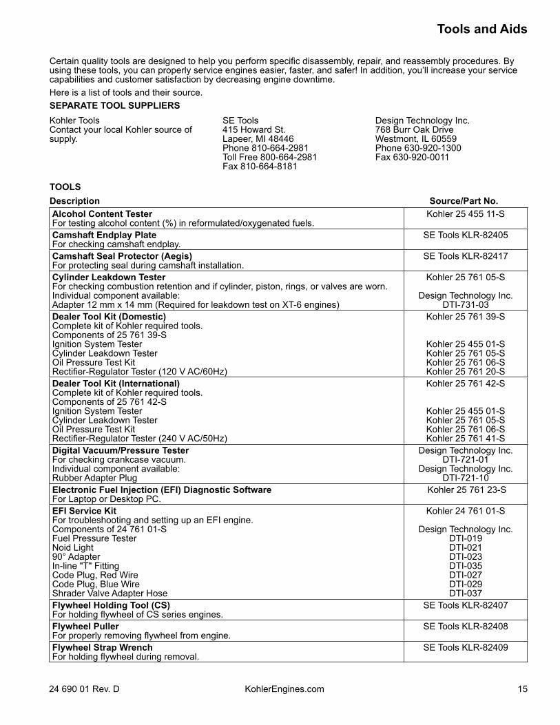
Certain quality tools are designed to help you perform specific disassembly, repair, and reassembly procedures. By using these tools, you can properly service engines easier, faster, and safer! In addition, you’ll increase your service capabilities and customer satisfaction by decreasing engine downtime.Here is a list of tools and their source.SEPARATE TOOL SUPPLIERSKohler Tools Contact your local Kohler source of supply.
SE Tools 415 Howard St. Lapeer, MI 48446 Phone 810-664-2981 Toll Free 800-664-2981 Fax 810-664-8181
Design Technology Inc. 768 Burr Oak Drive Westmont, IL 60559 Phone 630-920-1300 Fax 630-920-0011
TOOLSDescription Source/Part No.Alcohol Content TesterFor testing alcohol content (%) in reformulated/oxygenated fuels.
Kohler 25 455 11-S
Camshaft Endplay PlateFor checking camshaft endplay.
SE Tools KLR-82405
Camshaft Seal Protector (Aegis)For protecting seal during camshaft installation.
SE Tools KLR-82417
Cylinder Leakdown TesterFor checking combustion retention and if cylinder, piston, rings, or valves are worn.Individual component available:Adapter 12 mm x 14 mm (Required for leakdown test on XT-6 engines)
Kohler 25 761 05-S
Design Technology Inc.DTI-731-03
Dealer Tool Kit (Domestic)Complete kit of Kohler required tools.Components of 25 761 39-SIgnition System TesterCylinder Leakdown TesterOil Pressure Test KitRectifier-Regulator Tester (120 V AC/60Hz)
Kohler 25 761 39-S
Kohler 25 455 01-SKohler 25 761 05-SKohler 25 761 06-SKohler 25 761 20-S
Dealer Tool Kit (International)Complete kit of Kohler required tools.Components of 25 761 42-SIgnition System TesterCylinder Leakdown TesterOil Pressure Test KitRectifier-Regulator Tester (240 V AC/50Hz)
Kohler 25 761 42-S
Kohler 25 455 01-SKohler 25 761 05-SKohler 25 761 06-SKohler 25 761 41-S
Digital Vacuum/Pressure TesterFor checking crankcase vacuum.Individual component available:Rubber Adapter Plug
Design Technology Inc.DTI-721-01
Design Technology Inc.DTI-721-10
Electronic Fuel Injection (EFI) Diagnostic SoftwareFor Laptop or Desktop PC.
Kohler 25 761 23-S
EFI Service KitFor troubleshooting and setting up an EFI engine.Components of 24 761 01-SFuel Pressure TesterNoid Light90° AdapterIn-line "T" FittingCode Plug, Red WireCode Plug, Blue WireShrader Valve Adapter Hose
Kohler 24 761 01-S
Design Technology Inc.DTI-019DTI-021DTI-023DTI-035DTI-027DTI-029DTI-037
Flywheel Holding Tool (CS) For holding flywheel of CS series engines.
SE Tools KLR-82407
Flywheel PullerFor properly removing flywheel from engine.
SE Tools KLR-82408
Flywheel Strap WrenchFor holding flywheel during removal.
SE Tools KLR-82409
Tools and Aids
16 24 690 01 Rev. DKohlerEngines.com
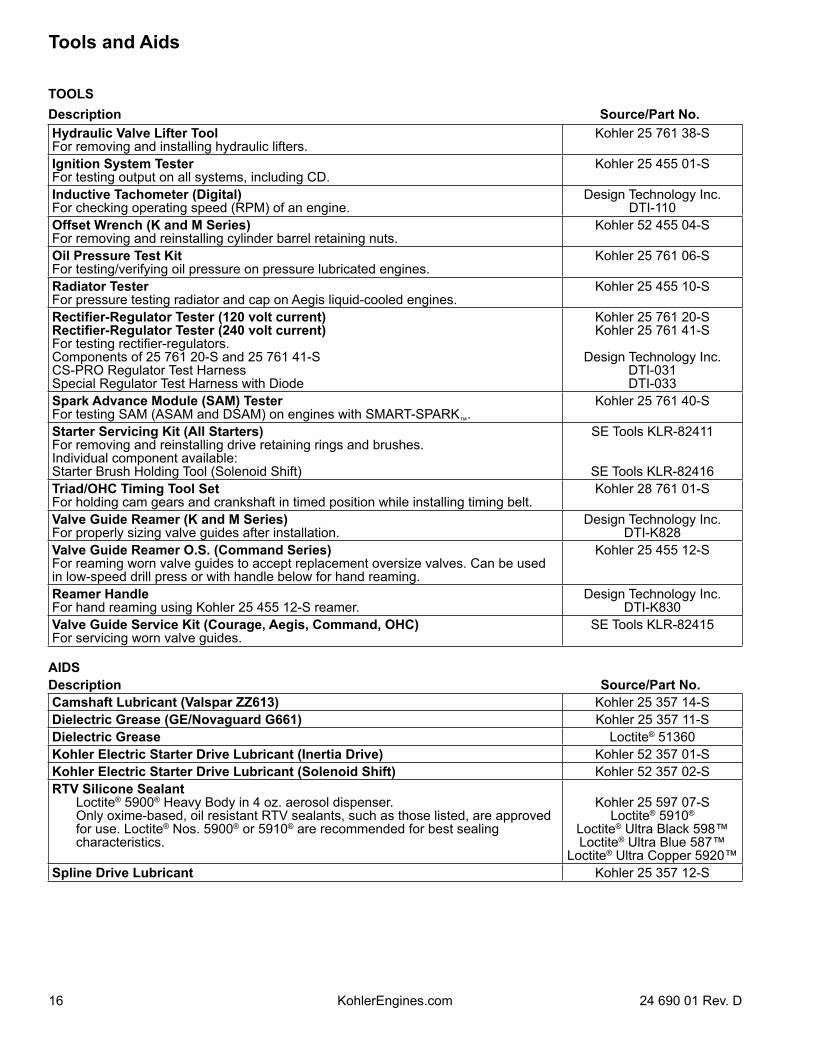
TOOLSDescription Source/Part No.Hydraulic Valve Lifter ToolFor removing and installing hydraulic lifters.
Kohler 25 761 38-S
Ignition System TesterFor testing output on all systems, including CD.
Kohler 25 455 01-S
Inductive Tachometer (Digital)For checking operating speed (RPM) of an engine.
Design Technology Inc.DTI-110
Offset Wrench (K and M Series) For removing and reinstalling cylinder barrel retaining nuts.
Kohler 52 455 04-S
Oil Pressure Test KitFor testing/verifying oil pressure on pressure lubricated engines.
Kohler 25 761 06-S
Radiator TesterFor pressure testing radiator and cap on Aegis liquid-cooled engines.
Kohler 25 455 10-S
Rectifier-Regulator Tester (120 volt current)Rectifier-Regulator Tester (240 volt current)For testing rectifier-regulators.Components of 25 761 20-S and 25 761 41-SCS-PRO Regulator Test HarnessSpecial Regulator Test Harness with Diode
Kohler 25 761 20-SKohler 25 761 41-S
Design Technology Inc.DTI-031DTI-033
Spark Advance Module (SAM) TesterFor testing SAM (ASAM and DSAM) on engines with SMART-SPARK™.
Kohler 25 761 40-S
Starter Servicing Kit (All Starters)For removing and reinstalling drive retaining rings and brushes.Individual component available:Starter Brush Holding Tool (Solenoid Shift)
SE Tools KLR-82411
SE Tools KLR-82416Triad/OHC Timing Tool SetFor holding cam gears and crankshaft in timed position while installing timing belt.
Kohler 28 761 01-S
Valve Guide Reamer (K and M Series)For properly sizing valve guides after installation.
Design Technology Inc.DTI-K828
Valve Guide Reamer O.S. (Command Series)For reaming worn valve guides to accept replacement oversize valves. Can be used in low-speed drill press or with handle below for hand reaming.
Kohler 25 455 12-S
Reamer HandleFor hand reaming using Kohler 25 455 12-S reamer.
Design Technology Inc.DTI-K830
Valve Guide Service Kit (Courage, Aegis, Command, OHC)For servicing worn valve guides.
SE Tools KLR-82415
AIDSDescription Source/Part No.Camshaft Lubricant (Valspar ZZ613) Kohler 25 357 14-SDielectric Grease (GE/Novaguard G661) Kohler 25 357 11-SDielectric Grease Loctite® 51360Kohler Electric Starter Drive Lubricant (Inertia Drive) Kohler 52 357 01-SKohler Electric Starter Drive Lubricant (Solenoid Shift) Kohler 52 357 02-SRTV Silicone Sealant Loctite® 5900® Heavy Body in 4 oz. aerosol dispenser. Only oxime-based, oil resistant RTV sealants, such as those listed, are approved
for use. Loctite® Nos. 5900® or 5910® are recommended for best sealing characteristics.
Kohler 25 597 07-SLoctite® 5910®
Loctite® Ultra Black 598™Loctite® Ultra Blue 587™
Loctite® Ultra Copper 5920™Spline Drive Lubricant Kohler 25 357 12-S
Tools and Aids
1724 690 01 Rev. D KohlerEngines.com
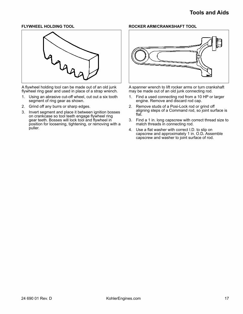
FLYWHEEL HOLDING TOOL ROCKER ARM/CRANKSHAFT TOOL
A flywheel holding tool can be made out of an old junk flywheel ring gear and used in place of a strap wrench.1. Using an abrasive cut-off wheel, cut out a six tooth
segment of ring gear as shown.2. Grind off any burrs or sharp edges.3. Invert segment and place it between ignition bosses
on crankcase so tool teeth engage flywheel ring gear teeth. Bosses will lock tool and flywheel in position for loosening, tightening, or removing with a puller.
A spanner wrench to lift rocker arms or turn crankshaft may be made out of an old junk connecting rod.1. Find a used connecting rod from a 10 HP or larger
engine. Remove and discard rod cap.2. Remove studs of a Posi-Lock rod or grind off
aligning steps of a Command rod, so joint surface is flat.
3. Find a 1 in. long capscrew with correct thread size to match threads in connecting rod.
4. Use a flat washer with correct I.D. to slip on capscrew and approximately 1 in. O.D. Assemble capscrew and washer to joint surface of rod.
Troubleshooting
18 24 690 01 Rev. DKohlerEngines.com
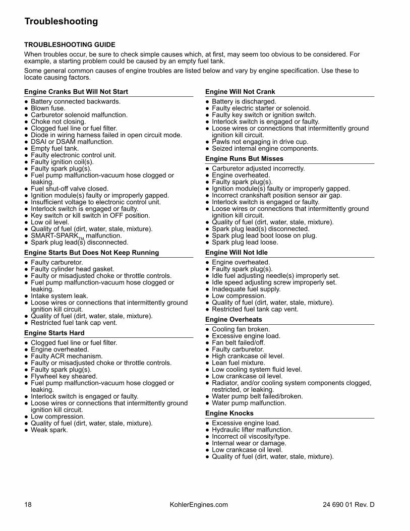
Engine Cranks But Will Not Start Battery connected backwards. Blown fuse. Carburetor solenoid malfunction. Choke not closing. Clogged fuel line or fuel filter. Diode in wiring harness failed in open circuit mode. DSAI or DSAM malfunction. Empty fuel tank. Faulty electronic control unit. Faulty ignition coil(s). Faulty spark plug(s). Fuel pump malfunction-vacuum hose clogged or
leaking. Fuel shut-off valve closed. Ignition module(s) faulty or improperly gapped. Insufficient voltage to electronic control unit. Interlock switch is engaged or faulty. Key switch or kill switch in OFF position. Low oil level. Quality of fuel (dirt, water, stale, mixture). SMART-SPARKTM malfunction. Spark plug lead(s) disconnected.Engine Starts But Does Not Keep Running Faulty carburetor. Faulty cylinder head gasket. Faulty or misadjusted choke or throttle controls. Fuel pump malfunction-vacuum hose clogged or
leaking. Intake system leak. Loose wires or connections that intermittently ground
ignition kill circuit. Quality of fuel (dirt, water, stale, mixture). Restricted fuel tank cap vent.Engine Starts Hard Clogged fuel line or fuel filter. Engine overheated. Faulty ACR mechanism. Faulty or misadjusted choke or throttle controls. Faulty spark plug(s). Flywheel key sheared. Fuel pump malfunction-vacuum hose clogged or
leaking. Interlock switch is engaged or faulty. Loose wires or connections that intermittently ground
ignition kill circuit. Low compression. Quality of fuel (dirt, water, stale, mixture). Weak spark.
TROUBLESHOOTING GUIDEWhen troubles occur, be sure to check simple causes which, at first, may seem too obvious to be considered. For example, a starting problem could be caused by an empty fuel tank.Some general common causes of engine troubles are listed below and vary by engine specification. Use these to locate causing factors.
Engine Will Not Crank Battery is discharged. Faulty electric starter or solenoid. Faulty key switch or ignition switch. Interlock switch is engaged or faulty. Loose wires or connections that intermittently ground
ignition kill circuit. Pawls not engaging in drive cup. Seized internal engine components.Engine Runs But Misses Carburetor adjusted incorrectly. Engine overheated. Faulty spark plug(s). Ignition module(s) faulty or improperly gapped. Incorrect crankshaft position sensor air gap. Interlock switch is engaged or faulty. Loose wires or connections that intermittently ground
ignition kill circuit. Quality of fuel (dirt, water, stale, mixture). Spark plug lead(s) disconnected. Spark plug lead boot loose on plug. Spark plug lead loose.Engine Will Not Idle Engine overheated. Faulty spark plug(s). Idle fuel adjusting needle(s) improperly set. Idle speed adjusting screw improperly set. Inadequate fuel supply. Low compression. Quality of fuel (dirt, water, stale, mixture). Restricted fuel tank cap vent.Engine Overheats Cooling fan broken. Excessive engine load. Fan belt failed/off. Faulty carburetor. High crankcase oil level. Lean fuel mixture. Low cooling system fluid level. Low crankcase oil level. Radiator, and/or cooling system components clogged,
restricted, or leaking. Water pump belt failed/broken. Water pump malfunction.Engine Knocks Excessive engine load. Hydraulic lifter malfunction. Incorrect oil viscosity/type. Internal wear or damage. Low crankcase oil level. Quality of fuel (dirt, water, stale, mixture).
1924 690 01 Rev. D KohlerEngines.com
Troubleshooting
Engine Loses Power Dirty air cleaner element. Engine overheated. Excessive engine load. Restricted exhaust. Faulty spark plug(s). High crankcase oil level. Incorrect governor setting. Low battery. Low compression. Low crankcase oil level. Quality of fuel (dirt, water, stale, mixture).Engine Uses Excessive Amount of Oil Loose or improperly torqued fasteners. Blown head gasket/overheated. Breather reed broken. Clogged, broken, or inoperative crankcase breather. Crankcase overfilled. Incorrect oil viscosity/type. Worn cylinder bore. Worn or broken piston rings. Worn valve stems/valve guides.Oil Leaks from Oil Seals, Gaskets Breather reed broken. Clogged, broken, or inoperative crankcase breather. Loose or improperly torqued fasteners. Piston blow by, or leaky valves. Restricted exhaust.
EXTERNAL ENGINE INSPECTIONNOTE: It is good practice to drain oil at a location away
from workbench. Be sure to allow ample time for complete drainage.
Before cleaning or disassembling engine, make a thorough inspection of its external appearance and condition. This inspection can give clues to what might be found inside engines (and cause) when it is disassembled. Check for buildup of dirt and debris on crankcase,
cooling fins, grass screen, and other external surfaces. Dirt or debris on these areas can cause overheating.
Check for obvious fuel and oil leaks, and damaged components. Excessive oil leakage can indicate a clogged or inoperative breather, worn or damaged seals or gaskets, or loose fasteners.
Check air cleaner cover and base for damage or indications of improper fit and seal.
Check air cleaner element. Look for holes, tears, cracked or damaged sealing surfaces, or other damage that could allow unfiltered air into engine. A dirty or clogged element could indicate insufficient or improper maintenance.
Check carburetor throat for dirt. Dirt in throat is further indication that air cleaner was not functioning properly.
Check if oil level is within operating range on dipstick. If it is above, sniff for gasoline odor.
Check condition of oil. Drain oil into a container; it should flow freely. Check for metal chips and other foreign particles.
Sludge is a natural by-product of combustion; a small accumulation is normal. Excessive sludge formation could indicate over rich fuel settings, weak ignition, overextended oil change interval or wrong weight or type of oil was used.
CLEANING ENGINE
WARNINGCleaning Solvents can cause severe injury or death.Use only in well ventilated areas away from ignition sources.
Carburetor cleaners and solvents are extremely flammable. Follow cleaner manufacturer’s warnings and instructions on its proper and safe use. Never use gasoline as a cleaning agent.
After inspecting external condition of engine, clean engine thoroughly before disassembly. Clean individual components as engine is disassembled. Only clean parts can be accurately inspected and gauged for wear or damage. There are many commercially available cleaners that will quickly remove grease, oil, and grime from engine parts. When such a cleaner is used, follow manufacturer’s instructions and safety precautions carefully.Make sure all traces of cleaner are removed before engine is reassembled and placed into operation. Even small amounts of these cleaners can quickly break down lubricating properties of engine oil.

Troubleshooting
20 24 690 01 Rev. DKohlerEngines.com
Condition ConclusionCrankcase breather clogged or inoperative. NOTE: If breather is integral part of valve cover and
cannot be serviced separately, replace valve cover and recheck pressure.
Disassemble breather, clean parts thoroughly, check sealing surfaces for flatness, reassemble, and recheck pressure.
Seals and/or gaskets leaking. Loose or improperly torque fasteners.
Replace all worn or damaged seals and gaskets. Make sure all fasteners are tightened securely. Use appropriate torque valves and sequences when necessary.
Piston blow by or leaky valves (confirm by inspecting components).
Recondition piston, rings, cylinder bore, valves and valves guides.
Restricted exhaust. Check exhaust screen/spark arrestor (if equipped). Clean or replace as needed. Repair or replace any other damaged/restricted muffler or exhaust system parts.
CRANKCASE VACUUM TEST
WARNING
Carbon Monoxide can cause severe nausea, fainting or death.Avoid inhaling exhaust fumes.
Engine exhaust gases contain poisonous carbon monoxide. Carbon monoxide is odorless, colorless, and can cause death if inhaled.
To test crankcase vacuum with manometer:1. Insert rubber stopper into oil fill hole. Be sure pinch
clamp is installed on hose and use tapered adapters to connect hose between stopper and one manometer tube. Leave other tube open to atmosphere. Check that water level in manometer is at 0 line. Make sure pinch clamp is closed.
2. Start engine and run no-load high speed.3. Open clamp and note water level in tube. Level in engine side should be a minimum of 10.2
cm (4 in.) above level in open side. If level in engine side is less than specified (low/no
vacuum), or level in engine side is lower than level in open side (pressure), check for conditions in table below.
4. Close pinch clamp before stopping engine.
To test crankcase vacuum with vacuum/pressure gauge:1. Remove dipstick or oil fill plug/cap.2. Install adapter into oil fill//dipstick tube opening,
upside down over end of a small diameter dipstick tube, or directly into engine if a tube is not used. Insert barbed gauge fitting into hole in stopper.
3. Run engine and observe gauge reading. Analog tester–needle movement to left of 0 is a
vacuum, and movement to right indicates a pressure. Digital tester–depress test button on top of tester. Crankcase vacuum should be a minimum of 10.2 cm
(4 in.) of water. If reading is below specification, or if pressure is present, check table below for possible causes and conclusions.
WARNING
Rotating Parts can cause severe injury.Stay away while engine is in operation.
Keep hands, feet, hair, and clothing away from all moving parts to prevent injury. Never operate engine with covers, shrouds, or guards removed.
A partial vacuum should be present in crankcase when engine is operating. Pressure in crankcase (normally caused by a clogged or improperly assembled breather) can cause oil to be forced out at oil seals, gaskets, or other available spots.Crankcase vacuum is best measured with either a water manometer or a vacuum gauge. Complete instructions are provided in kits.
2124 690 01 Rev. D KohlerEngines.com
Troubleshooting
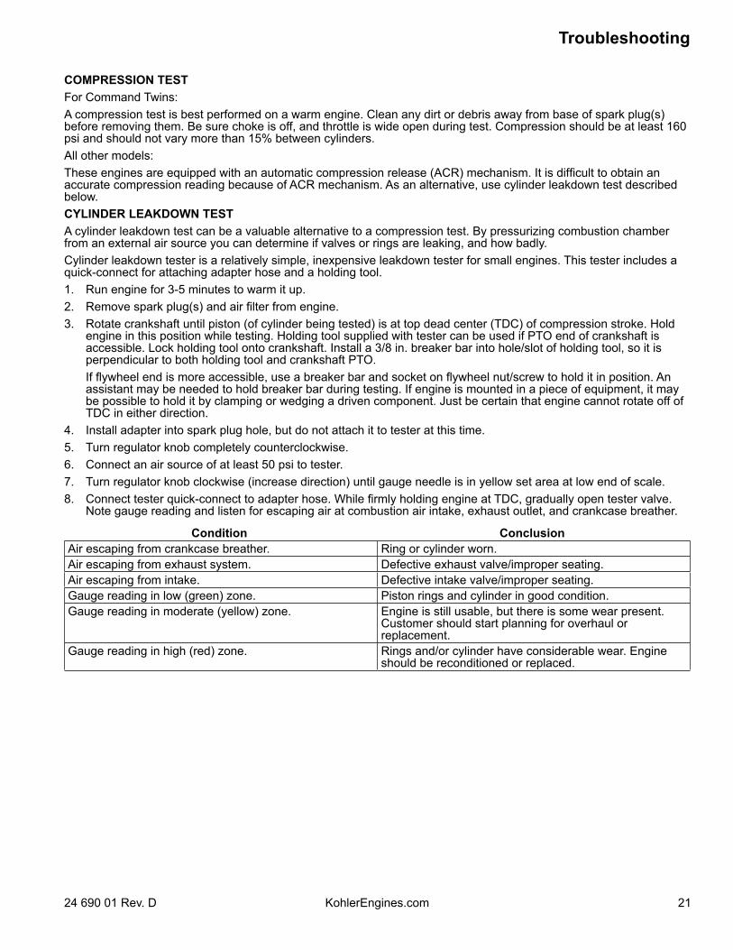
COMPRESSION TESTFor Command Twins:A compression test is best performed on a warm engine. Clean any dirt or debris away from base of spark plug(s) before removing them. Be sure choke is off, and throttle is wide open during test. Compression should be at least 160 psi and should not vary more than 15% between cylinders.All other models:These engines are equipped with an automatic compression release (ACR) mechanism. It is difficult to obtain an accurate compression reading because of ACR mechanism. As an alternative, use cylinder leakdown test described below.CYLINDER LEAKDOWN TESTA cylinder leakdown test can be a valuable alternative to a compression test. By pressurizing combustion chamber from an external air source you can determine if valves or rings are leaking, and how badly.Cylinder leakdown tester is a relatively simple, inexpensive leakdown tester for small engines. This tester includes a quick-connect for attaching adapter hose and a holding tool.1. Run engine for 3-5 minutes to warm it up.2. Remove spark plug(s) and air filter from engine.3. Rotate crankshaft until piston (of cylinder being tested) is at top dead center (TDC) of compression stroke. Hold
engine in this position while testing. Holding tool supplied with tester can be used if PTO end of crankshaft is accessible. Lock holding tool onto crankshaft. Install a 3/8 in. breaker bar into hole/slot of holding tool, so it is perpendicular to both holding tool and crankshaft PTO.
If flywheel end is more accessible, use a breaker bar and socket on flywheel nut/screw to hold it in position. An assistant may be needed to hold breaker bar during testing. If engine is mounted in a piece of equipment, it may be possible to hold it by clamping or wedging a driven component. Just be certain that engine cannot rotate off of TDC in either direction.
4. Install adapter into spark plug hole, but do not attach it to tester at this time.5. Turn regulator knob completely counterclockwise.6. Connect an air source of at least 50 psi to tester.7. Turn regulator knob clockwise (increase direction) until gauge needle is in yellow set area at low end of scale.8. Connect tester quick-connect to adapter hose. While firmly holding engine at TDC, gradually open tester valve.
Note gauge reading and listen for escaping air at combustion air intake, exhaust outlet, and crankcase breather.
Condition ConclusionAir escaping from crankcase breather. Ring or cylinder worn.Air escaping from exhaust system. Defective exhaust valve/improper seating.Air escaping from intake. Defective intake valve/improper seating.Gauge reading in low (green) zone. Piston rings and cylinder in good condition.Gauge reading in moderate (yellow) zone. Engine is still usable, but there is some wear present.
Customer should start planning for overhaul or replacement.
Gauge reading in high (red) zone. Rings and/or cylinder have considerable wear. Engine should be reconditioned or replaced.
Air Cleaner/Intake
22 24 690 01 Rev. DKohlerEngines.com
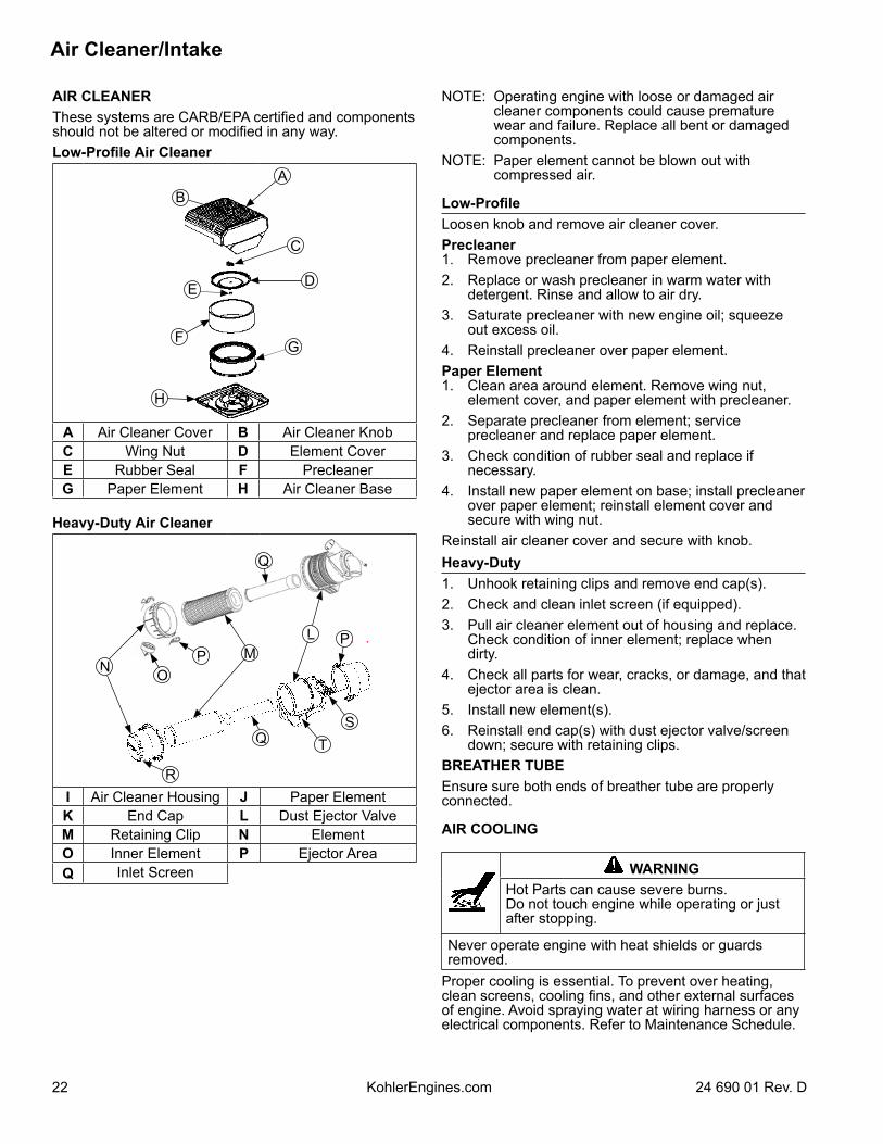
AIR CLEANERThese systems are CARB/EPA certified and components should not be altered or modified in any way.Low-Profile Air Cleaner
B
E
F
H
A
C
D
G
A Air Cleaner Cover B Air Cleaner KnobC Wing Nut D Element CoverE Rubber Seal F PrecleanerG Paper Element H Air Cleaner Base
Heavy-Duty Air Cleaner
OM
L
N
R
Q
P
Q
P
ST
I Air Cleaner Housing J Paper ElementK End Cap L Dust Ejector ValveM Retaining Clip N ElementO Inner Element P Ejector AreaQ Inlet Screen
NOTE: Operating engine with loose or damaged air cleaner components could cause premature wear and failure. Replace all bent or damaged components.
NOTE: Paper element cannot be blown out with compressed air.
Low-ProfileLoosen knob and remove air cleaner cover.Precleaner1. Remove precleaner from paper element.2. Replace or wash precleaner in warm water with
detergent. Rinse and allow to air dry.3. Saturate precleaner with new engine oil; squeeze
out excess oil.4. Reinstall precleaner over paper element.Paper Element1. Clean area around element. Remove wing nut,
element cover, and paper element with precleaner.2. Separate precleaner from element; service
precleaner and replace paper element.3. Check condition of rubber seal and replace if
necessary.4. Install new paper element on base; install precleaner
over paper element; reinstall element cover and secure with wing nut.
Reinstall air cleaner cover and secure with knob.Heavy-Duty1. Unhook retaining clips and remove end cap(s). 2. Check and clean inlet screen (if equipped).3. Pull air cleaner element out of housing and replace.
Check condition of inner element; replace when dirty.
4. Check all parts for wear, cracks, or damage, and that ejector area is clean.
5. Install new element(s).6. Reinstall end cap(s) with dust ejector valve/screen
down; secure with retaining clips.BREATHER TUBEEnsure sure both ends of breather tube are properly connected.
AIR COOLING
WARNINGHot Parts can cause severe burns.Do not touch engine while operating or just after stopping.
Never operate engine with heat shields or guards removed.
Proper cooling is essential. To prevent over heating, clean screens, cooling fins, and other external surfaces of engine. Avoid spraying water at wiring harness or any electrical components. Refer to Maintenance Schedule.
2324 690 01 Rev. D KohlerEngines.com
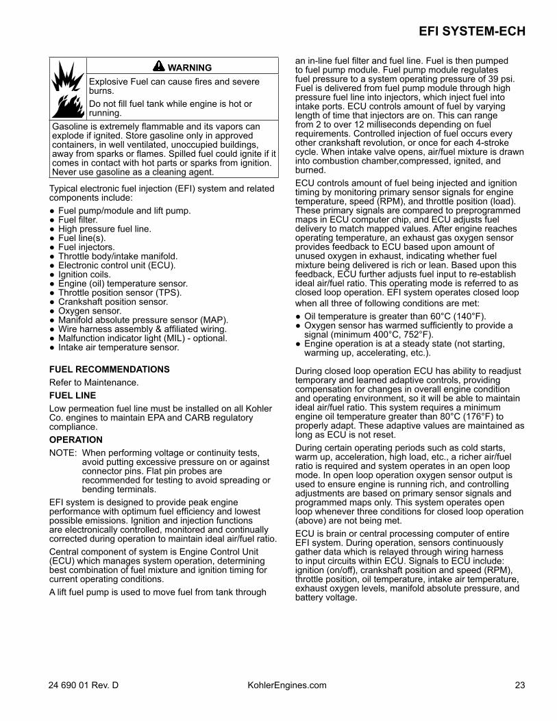
EFI SYSTEM-ECH
WARNINGExplosive Fuel can cause fires and severe burns.Do not fill fuel tank while engine is hot or running.
Gasoline is extremely flammable and its vapors can explode if ignited. Store gasoline only in approved containers, in well ventilated, unoccupied buildings, away from sparks or flames. Spilled fuel could ignite if it comes in contact with hot parts or sparks from ignition. Never use gasoline as a cleaning agent.
Typical electronic fuel injection (EFI) system and related components include: Fuel pump/module and lift pump. Fuel filter. High pressure fuel line. Fuel line(s). Fuel injectors. Throttle body/intake manifold. Electronic control unit (ECU). Ignition coils. Engine (oil) temperature sensor. Throttle position sensor (TPS). Crankshaft position sensor. Oxygen sensor. Manifold absolute pressure sensor (MAP). Wire harness assembly & affiliated wiring. Malfunction indicator light (MIL) - optional. Intake air temperature sensor.
FUEL RECOMMENDATIONSRefer to Maintenance.FUEL LINELow permeation fuel line must be installed on all Kohler Co. engines to maintain EPA and CARB regulatory compliance. OPERATIONNOTE: When performing voltage or continuity tests,
avoid putting excessive pressure on or against connector pins. Flat pin probes are recommended for testing to avoid spreading or bending terminals.
EFI system is designed to provide peak engine performance with optimum fuel efficiency and lowest possible emissions. Ignition and injection functions are electronically controlled, monitored and continually corrected during operation to maintain ideal air/fuel ratio. Central component of system is Engine Control Unit (ECU) which manages system operation, determining best combination of fuel mixture and ignition timing for current operating conditions. A lift fuel pump is used to move fuel from tank through
an in-line fuel filter and fuel line. Fuel is then pumped to fuel pump module. Fuel pump module regulates fuel pressure to a system operating pressure of 39 psi. Fuel is delivered from fuel pump module through high pressure fuel line into injectors, which inject fuel into intake ports. ECU controls amount of fuel by varying length of time that injectors are on. This can range from 2 to over 12 milliseconds depending on fuel requirements. Controlled injection of fuel occurs every other crankshaft revolution, or once for each 4-stroke cycle. When intake valve opens, air/fuel mixture is drawn into combustion chamber,compressed, ignited, and burned.ECU controls amount of fuel being injected and ignition timing by monitoring primary sensor signals for engine temperature, speed (RPM), and throttle position (load). These primary signals are compared to preprogrammed maps in ECU computer chip, and ECU adjusts fuel delivery to match mapped values. After engine reaches operating temperature, an exhaust gas oxygen sensor provides feedback to ECU based upon amount of unused oxygen in exhaust, indicating whether fuel mixture being delivered is rich or lean. Based upon this feedback, ECU further adjusts fuel input to re-establish ideal air/fuel ratio. This operating mode is referred to as closed loop operation. EFI system operates closed loop when all three of following conditions are met: Oil temperature is greater than 60°C (140°F). Oxygen sensor has warmed sufficiently to provide a
signal (minimum 400°C, 752°F). Engine operation is at a steady state (not starting,
warming up, accelerating, etc.).
During closed loop operation ECU has ability to readjust temporary and learned adaptive controls, providing compensation for changes in overall engine condition and operating environment, so it will be able to maintain ideal air/fuel ratio. This system requires a minimum engine oil temperature greater than 80°C (176°F) to properly adapt. These adaptive values are maintained as long as ECU is not reset. During certain operating periods such as cold starts, warm up, acceleration, high load, etc., a richer air/fuel ratio is required and system operates in an open loop mode. In open loop operation oxygen sensor output is used to ensure engine is running rich, and controlling adjustments are based on primary sensor signals and programmed maps only. This system operates open loop whenever three conditions for closed loop operation (above) are not being met.ECU is brain or central processing computer of entire EFI system. During operation, sensors continuously gather data which is relayed through wiring harness to input circuits within ECU. Signals to ECU include: ignition (on/off), crankshaft position and speed (RPM), throttle position, oil temperature, intake air temperature, exhaust oxygen levels, manifold absolute pressure, and battery voltage.
EFI SYSTEM-ECH
24 24 690 01 Rev. DKohlerEngines.com
ECU compares input signals to programmed maps in its memory to determine appropriate fuel and spark requirements for immediate operating conditions. ECU then sends output signals to set injector duration and ignition timing.ECU continually performs a diagnostic check of itself, each of sensors, and system performance. If a fault is detected, ECU can turn on a Malfunction Indicator Light (MIL) (if equipped) on equipment control panel, store fault code in its fault memory, and go into a default operating mode. Depending on significance or severity of fault, normal operation may continue. A technician can access stored fault code using a blink code diagnosis flashed out through MIL. An optional computer software diagnostic program is also available, see Tools and Aids.ECU requires a minimum of 6.0 volts to operate.To prevent engine over-speed and possible failure, a rev-limiting feature is programmed into ECU. If maximum RPM limit (4500) is exceeded, ECU suppresses injection signals, cutting off fuel flow. This process repeats itself in rapid succession, limiting operation to preset maximum.Wiring harness used in EFI system connects electrical components, providing current and ground paths for system to operate. All input and output signaling occurs through two special all weather connectors that attach and lock to ECU. Connectors are Black and Grey and keyed differently to prevent being attached to ECU incorrectly.Condition of wiring, connectors, and terminal connections is essential to system function and performance. Corrosion, moisture, and poor connections are as likely cause of operating problems and system errors as an actual component. Refer to Electrical System for additional information.EFI system is a 12 VDC negative ground system, designed to operate down to a minimum of 6.0 volts. If system voltage drops below this level, operation of voltage sensitive components such as ECU, fuel pump, ignition coils, and injectors will be intermittent or disrupted, causing erratic operation or hard starting. A fully charged, 12 volt battery with a minimum of 350 cold cranking amps is important in maintaining steady and reliable system operation. Battery condition and state of charge should always be checked first when troubleshooting an operational problem. Keep in mind that EFI-related problems are often caused by wiring harness or connections. Even small amounts of corrosion or oxidation on terminals can interfere with milliamp currents used in system operation. Cleaning connectors and grounds will solve problems in many cases. In an emergency situation, simply disconnecting and reconnecting connectors may clean up contacts enough to restore operation, at least temporarily.If a fault code indicates a problem with an electrical component, disconnect ECU connector and test for continuity between component connector terminals and corresponding terminals in ECU connector using an ohmmeter. Little or no resistance should be measured, indicating that wiring of that particular circuit is OK.
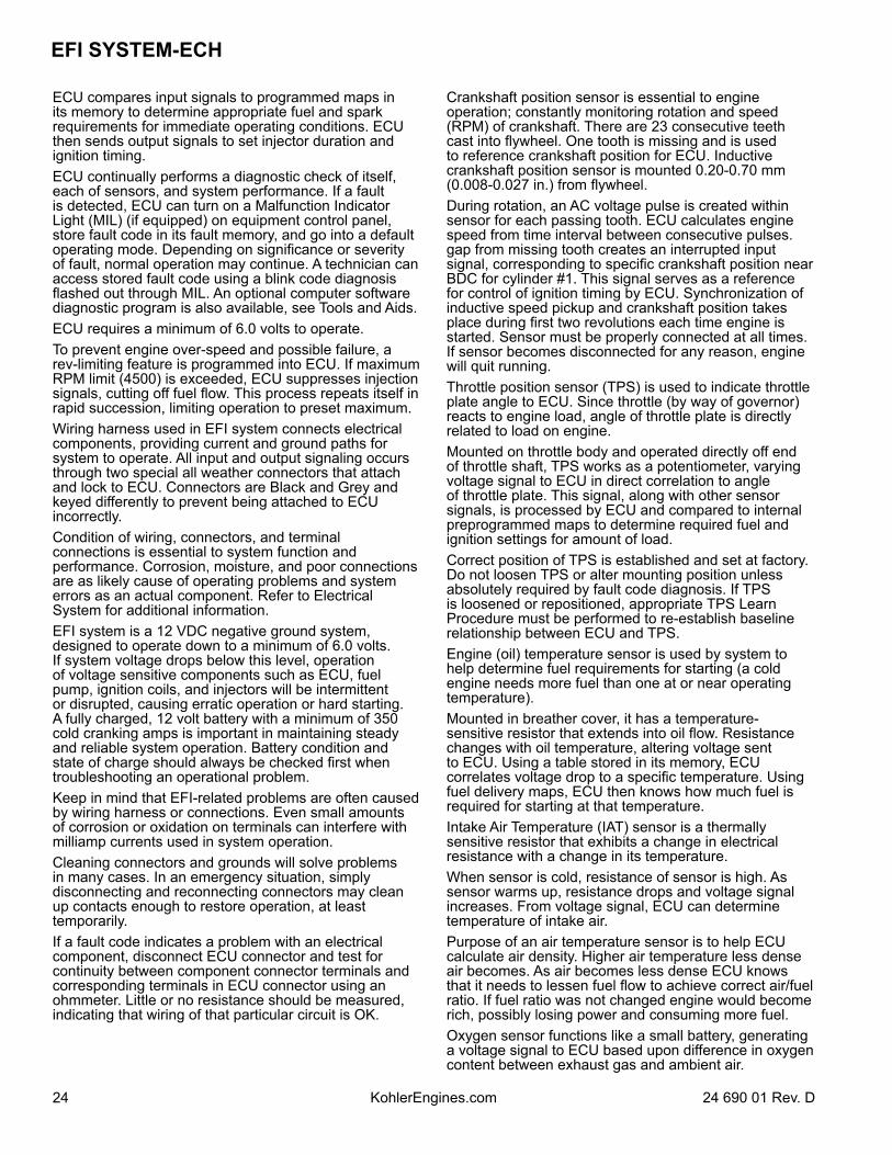
Crankshaft position sensor is essential to engine operation; constantly monitoring rotation and speed (RPM) of crankshaft. There are 23 consecutive teeth cast into flywheel. One tooth is missing and is used to reference crankshaft position for ECU. Inductive crankshaft position sensor is mounted 0.20-0.70 mm (0.008-0.027 in.) from flywheel.During rotation, an AC voltage pulse is created within sensor for each passing tooth. ECU calculates engine speed from time interval between consecutive pulses. gap from missing tooth creates an interrupted input signal, corresponding to specific crankshaft position near BDC for cylinder #1. This signal serves as a reference for control of ignition timing by ECU. Synchronization of inductive speed pickup and crankshaft position takes place during first two revolutions each time engine is started. Sensor must be properly connected at all times. If sensor becomes disconnected for any reason, engine will quit running.Throttle position sensor (TPS) is used to indicate throttle plate angle to ECU. Since throttle (by way of governor) reacts to engine load, angle of throttle plate is directly related to load on engine.Mounted on throttle body and operated directly off end of throttle shaft, TPS works as a potentiometer, varying voltage signal to ECU in direct correlation to angle of throttle plate. This signal, along with other sensor signals, is processed by ECU and compared to internal preprogrammed maps to determine required fuel and ignition settings for amount of load. Correct position of TPS is established and set at factory. Do not loosen TPS or alter mounting position unless absolutely required by fault code diagnosis. If TPS is loosened or repositioned, appropriate TPS Learn Procedure must be performed to re-establish baseline relationship between ECU and TPS.Engine (oil) temperature sensor is used by system to help determine fuel requirements for starting (a cold engine needs more fuel than one at or near operating temperature). Mounted in breather cover, it has a temperature-sensitive resistor that extends into oil flow. Resistance changes with oil temperature, altering voltage sent to ECU. Using a table stored in its memory, ECU correlates voltage drop to a specific temperature. Using fuel delivery maps, ECU then knows how much fuel is required for starting at that temperature.Intake Air Temperature (IAT) sensor is a thermally sensitive resistor that exhibits a change in electrical resistance with a change in its temperature.When sensor is cold, resistance of sensor is high. As sensor warms up, resistance drops and voltage signal increases. From voltage signal, ECU can determine temperature of intake air.Purpose of an air temperature sensor is to help ECU calculate air density. Higher air temperature less dense air becomes. As air becomes less dense ECU knows that it needs to lessen fuel flow to achieve correct air/fuel ratio. If fuel ratio was not changed engine would become rich, possibly losing power and consuming more fuel.Oxygen sensor functions like a small battery, generating a voltage signal to ECU based upon difference in oxygen content between exhaust gas and ambient air.
2524 690 01 Rev. D KohlerEngines.com
EFI SYSTEM-ECH
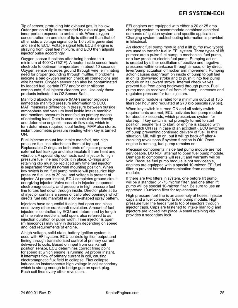
Tip of sensor, protruding into exhaust gas, is hollow. Outer portion of tip is surrounded by exhaust gas, with inner portion exposed to ambient air. When oxygen concentration on one side of tip is different than that of other side, a voltage signal up to 1.0 volt is generated and sent to ECU. Voltage signal tells ECU if engine is straying from ideal fuel mixture, and ECU then adjusts injector pulse accordingly.Oxygen sensor functions after being heated to a minimum of 400°C (752°F). A heater inside sensor heats electrode to optimum temperature in about 10 seconds. Oxygen sensor receives ground through wire, eliminating need for proper grounding through muffler. If problems indicate a bad oxygen sensor, check all connections and wire harness. Oxygen sensor can also be contaminated by leaded fuel, certain RTV and/or other silicone compounds, fuel injector cleaners, etc. Use only those products indicated as O2 Sensor Safe.Manifold absolute pressure (MAP) sensor provides immediate manifold pressure information to ECU. MAP measures difference in pressure between outside atmosphere and vacuum level inside intake manifold and monitors pressure in manifold as primary means of detecting load. Data is used to calculate air density and determine engine's mass air flow rate, which in turn determines required ideal fueling. MAP also stores instant barometric pressure reading when key is turned ON.Fuel injectors mount into intake manifold, and high pressure fuel line attaches to them at top end. Replaceable O-rings on both ends of injector prevent external fuel leakage and also insulate it from heat and vibration. A special clip connects each injector to high pressure fuel line and holds it in place. O-rings and retaining clip must be replaced any time fuel injector is separated from its normal mounting position. When key switch is on, fuel pump module will pressurize high pressure fuel line to 39 psi, and voltage is present at injector. At proper instant, ECU completes ground circuit, energizing injector. Valve needle in injector is opened electromagnetically, and pressure in high pressure fuel line forces fuel down through inside. Director plate at tip of injector contains a series of calibrated openings which directs fuel into manifold in a cone-shaped spray pattern.Injectors have sequential fueling that open and close once every other crankshaft revolution. Amount of fuel injected is controlled by ECU and determined by length of time valve needle is held open, also referred to as injection duration or pulse width. Time injector is open (milliseconds) may vary in duration depending on speed and load requirements of engine.A high-voltage, solid-state, battery ignition system is used with EFI system. ECU controls ignition output and timing through transistorized control of primary current delivered to coils. Based on input from crankshaft position sensor, ECU determines correct firing point for speed at which engine is running. At proper instant, it interrupts flow of primary current in coil, causing electromagnetic flux field to collapse. Flux collapse induces an instantaneous high voltage in coil secondary which is strong enough to bridge gap on spark plug. Each coil fires every other revolution.
EFI engines are equipped with either a 20 or 25 amp charging system to accommodate combined electrical demands of ignition system and specific application. Charging system troubleshooting information is provided in Electrical.An electric fuel pump module and a lift pump (two types) are used to transfer fuel in EFI system. Three types of lift pumps: are a pulse fuel pump, a mechanical fuel pump, or a low pressure electric fuel pump. Pumping action is created by either oscillation of positive and negative pressures within crankcase through a hose, or by direct lever/pump actuation off rocker arm movement. Pumping action causes diaphragm on inside of pump to pull fuel in on its downward stroke and to push it into fuel pump module on its upward stroke. Internal check valves prevent fuel from going backward through pump. Fuel pump module receives fuel from lift pump, increases and regulates pressure for fuel injectors.Fuel pump module is rated for a minimum output of 13.5 liters per hour and regulated at 270 kilo pascals (39 psi).When key switch is turned ON and all safety switch requirements are met, ECU activates fuel pump module for about six seconds, which pressurizes system for start-up. If key switch is not promptly turned to start position, engine fails to start, or engine is stopped with key switch ON (as in case of an accident), ECU switches off pump preventing continued delivery of fuel. In this situation, MIL will go on, but it will go back off after 4 cranking revolutions if system function is OK. Once engine is running, fuel pump remains on.Precision components inside fuel pump module are not serviceable. DO NOT attempt to open fuel pump module. Damage to components will result and warranty will be void. Because fuel pump module is not serviceable, engines are equipped with a special 10-micron EFI fuel filter to prevent harmful contamination from entering module.If there are two filters in system, one before lift pump will be a standard 51-75 micron filter, and one after lift pump will be special 10-micron filter. Be sure to use an approved 10-micron filter for replacement.High pressure fuel line is an assembly of hoses, injector caps and a fuel connector to fuel pump module. High pressure fuel line feeds fuel to top of injectors through injector caps. Caps are fastened to intake manifold and injectors are locked into place. A small retaining clip provides a secondary lock.
EFI SYSTEM-ECH
26 24 690 01 Rev. DKohlerEngines.com
High pressure fuel line is serviced as a complete assembly to prevent tampering and safety hazards. Components are not individually serviceable.
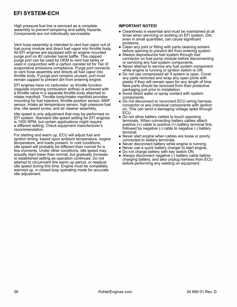
Vent hose assembly is intended to vent fuel vapor out of fuel pump module and direct fuel vapor into throttle body. All EFI engines are equipped with an engine mounted purge port on #2 cylinder barrel baffle. This capped purge port can be used by OEM to vent fuel tanks or used in conjunction with a carbon canister kit for Tier III evaporative emissions compliance. Purge port connects to vent hose assembly and directs all fuel vapor into throttle body. If purge port remains unused, port must remain capped to prevent dirt from entering engine.EFI engines have no carburetor, so throttle function (regulate incoming combustion airflow) is achieved with a throttle valve in a separate throttle body attached to intake manifold. Throttle body/intake manifold provides mounting for fuel injectors, throttle position sensor, MAP sensor, intake air temperature sensor, high pressure fuel line, idle speed screw, and air cleaner assembly.Idle speed is only adjustment that may be performed on EFI system. Standard idle speed setting for EFI engines is 1500 RPM, but certain applications might require a different setting. Check equipment manufacturer’s recommendation.For starting and warm up, ECU will adjust fuel and ignition timing, based upon ambient temperature, engine temperature, and loads present. In cold conditions, idle speed will probably be different than normal for a few moments. Under other conditions, idle speed may actually start lower than normal, but gradually increase to established setting as operation continues. Do not attempt to circumvent this warm up period, or readjust idle speed during this time. Engine must be completely warmed up, in closed loop operating mode for accurate idle adjustment.
IMPORTANT NOTES! Cleanliness is essential and must be maintained at all
times when servicing or working on EFI system. Dirt, even in small quantities, can cause significant problems.
Clean any joint or fitting with parts cleaning solvent before opening to prevent dirt from entering system.
Always depressurize fuel system through fuel connector on fuel pump module before disconnecting or servicing any fuel system components.
Never attempt to service any fuel system component while engine is running or ignition switch is ON.
Do not use compressed air if system is open. Cover any parts removed and wrap any open joints with plastic if they will remain open for any length of time. New parts should be removed from their protective packaging just prior to installation.
Avoid direct water or spray contact with system components.
Do not disconnect or reconnect ECU wiring harness connector or any individual components with ignition on. This can send a damaging voltage spike through ECU.
Do not allow battery cables to touch opposing terminals. When connecting battery cables attach positive (+) cable to positive (+) battery terminal first, followed by negative (-) cable to negative (-) battery terminal.
Never start engine when cables are loose or poorly connected to battery terminals.
Never disconnect battery while engine is running. Never use a quick battery charger to start engine. Do not charge battery with key switch ON. Always disconnect negative (-) battery cable before
charging battery, and also unplug harness from ECU before performing any welding on equipment.
2724 690 01 Rev. D KohlerEngines.com
EFI SYSTEM-ECH
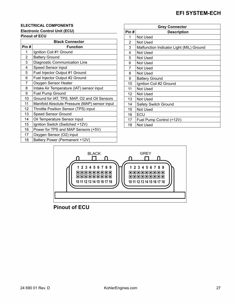
ELECTRICAL COMPONENTSElectronic Control Unit (ECU)Pinout of ECU
Black ConnectorPin # Function
1 Ignition Coil #1 Ground2 Battery Ground3 Diagnostic Communication Line4 Speed Sensor input5 Fuel Injector Output #1 Ground6 Fuel Injector Output #2 Ground7 Oxygen Sensor Heater8 Intake Air Temperature (IAT) sensor input9 Fuel Pump Ground
10 Ground for IAT, TPS, MAP, O2 and Oil Sensors11 Manifold Absolute Pressure (MAP) sensor input12 Throttle Position Sensor (TPS) input13 Speed Sensor Ground14 Oil Temperature Sensor input15 Ignition Switch (Switched +12V)16 Power for TPS and MAP Sensors (+5V)17 Oxygen Sensor (O2) input18 Battery Power (Permanent +12V)
Grey ConnectorPin # Description
1 Not Used2 Not Used3 Malfunction Indicator Light (MIL) Ground4 Not Used5 Not Used6 Not Used7 Not Used8 Not Used9 Battery Ground10 Ignition Coil #2 Ground11 Not Used12 Not Used13 Not Used14 Safety Switch Ground15 Not Used16 ECU17 Fuel Pump Control (+12V)18 Not Used
Pinout of ECU
EFI SYSTEM-ECH
28 24 690 01 Rev. DKohlerEngines.com
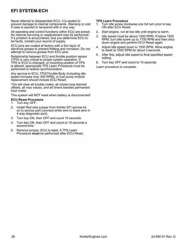
Never attempt to disassemble ECU. It is sealed to prevent damage to internal components. Warranty is void if case is opened or tampered with in any way.All operating and control functions within ECU are preset. No internal servicing or readjustment may be performed. If a problem is encountered, and you determine ECU to be faulty, contact your source of supply. ECU pins are coated at factory with a thin layer of electrical grease to prevent fretting and corrosion. Do not attempt to remove grease from ECU pins.Relationship between ECU and throttle position sensor (TPS) is very critical to proper system operation. If TPS or ECU is changed, or mounting position of TPS is altered, appropriate TPS Learn Procedure must be performed to restore synchronization.Any service to ECU, TPS/Throttle Body (including idle speed increase over 300 RPM), or fuel pump module replacement should include ECU Reset.This will clear all trouble codes, all closed loop learned offsets, all max values, and all timers besides permanent hour meter.This system will NOT reset when battery is disconnected!ECU Reset Procedure1. Turn key OFF.2. Install Red wire jumper from Kohler EFI service kit
on to service port (connect white wire to black wire in 4 way diagnostic port).
3. Turn key ON, then OFF and count 10 seconds.4. Turn key ON, then OFF and count to 10 seconds a
second time.5. Remove jumper, ECU is reset. A TPS Learn
Procedure must be performed after ECU Reset.
TPS Learn Procedure1. Turn idle screw clockwise one full turn prior to key
ON after ECU Reset.2. Start engine, run at low idle until engine is warm.3. Idle speed must be above 1500 RPM. If below 1500
RPM, turn idle screw up to 1700 RPM and then shut down engine and perform ECU Reset again.
4. Adjust idle speed down to 1500 RPM. Allow engine to dwell at 1500 RPM for about 3 seconds.
5. After this, adjust idle speed to final specified speed setting.
6. Turn key OFF and count to 10 seconds.Learn procedure is complete.
2924 690 01 Rev. D KohlerEngines.com
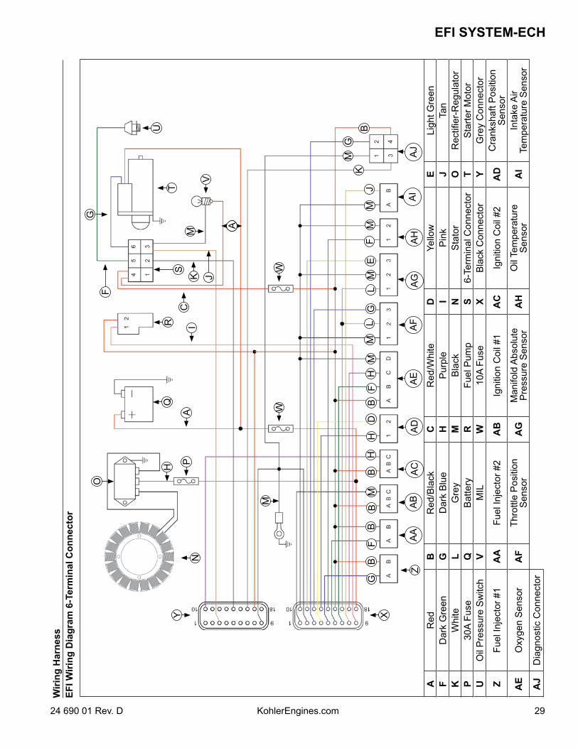
EFI SYSTEM-ECHW
iring
Har
ness
EFI W
iring
Dia
gram
6-T
erm
inal
Con
nect
or
AR
edB
Red
/Bla
ckC
Red
/Whi
teD
Yello
wE
Ligh
t Gre
enF
Dar
k G
reen
GD
ark
Blu
eH
Pur
ple
IP
ink
JTa
nK
Whi
teL
Gre
yM
Bla
ckN
Sta
tor
OR
ectifi
er-R
egul
ator
P30
A Fu
seQ
Bat
tery
RFu
el P
ump
S6-
Term
inal
Con
nect
orT
Sta
rter M
otor
UO
il P
ress
ure
Sw
itch
VM
ILW
10A
Fuse
XB
lack
Con
nect
orY
Gre
y C
onne
ctor
ZFu
el In
ject
or #
1A
AFu
el In
ject
or #
2A
BIg
nitio
n C
oil #
1A
CIg
nitio
n C
oil #
2A
DC
rank
shaf
t Pos
ition
S
enso
r
AE
Oxy
gen
Sen
sor
AF
Thro
ttle
Pos
ition
Sen
sor
AG
Man
ifold
Abs
olut
e P
ress
ure
Sen
sor
AH
Oil
Tem
pera
ture
S
enso
rA
IIn
take
Air
Tem
pera
ture
Sen
sor
AJ
Dia
gnos
tic C
onne
ctor
C
J
GB
FB
BM
BH
HD
BF
HM
ML
GL
ME
FM
MJ
KM
G
B
K
WAPH
IV
W
O
Y
M
M
A
N
X
QR
T
A
U
ZA
AA
BA
CA
DA
EA
FA
GA
HA
IA
J
GF
S
EFI SYSTEM-ECH
30 24 690 01 Rev. DKohlerEngines.com
WB
A
D
MW
K
I
MS
PHY
OC
AK
X
N
QR
J
G U
T
GB
FB
BM
BH
HD
BF
HM
ML
GL
ME
FM
MJ
KM
GB
ZA
DA
JA
HA
GA
FA
EA
DA
CA
BA
A
VD
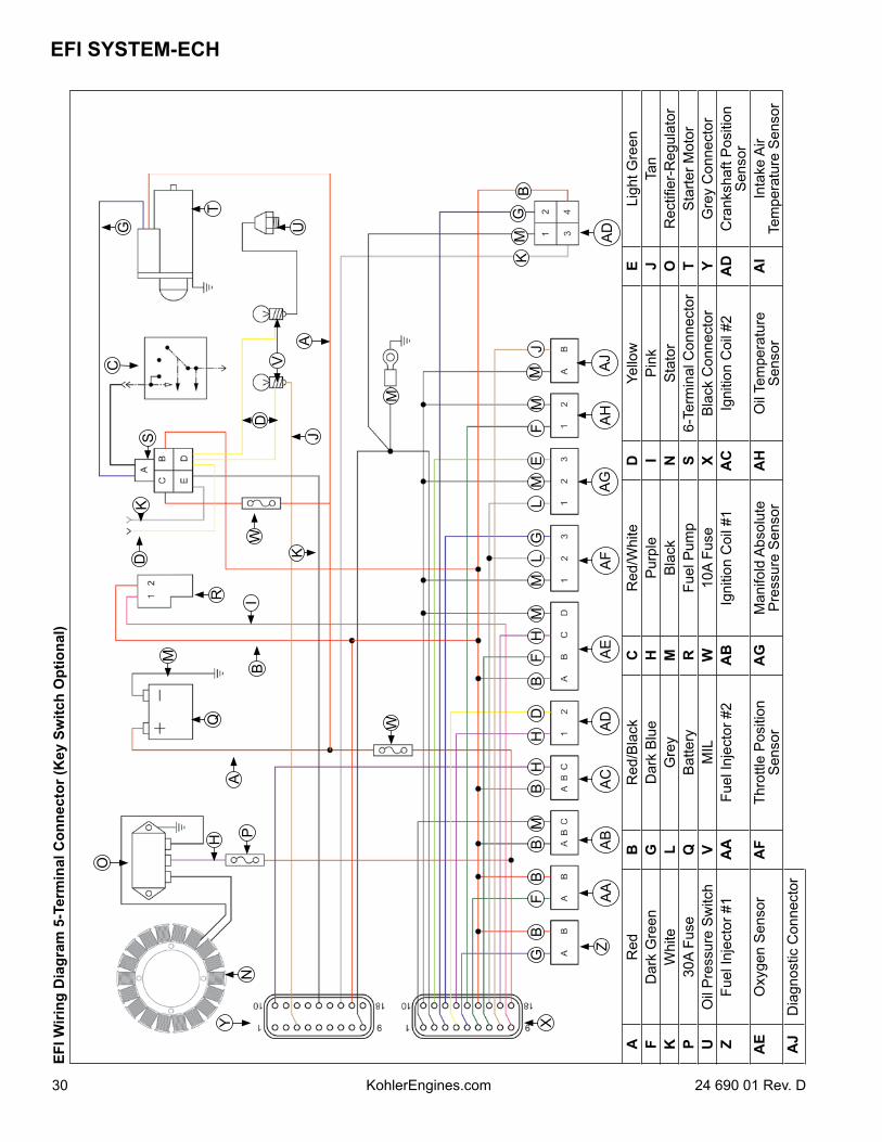
EFI W
iring
Dia
gram
5-T
erm
inal
Con
nect
or (K
ey S
witc
h O
ptio
nal)
AR
edB
Red
/Bla
ckC
Red
/Whi
teD
Yello
wE
Ligh
t Gre
enF
Dar
k G
reen
GD
ark
Blu
eH
Pur
ple
IP
ink
JTa
nK
Whi
teL
Gre
yM
Bla
ckN
Sta
tor
OR
ectifi
er-R
egul
ator
P30
A Fu
seQ
Bat
tery
RFu
el P
ump
S6-
Term
inal
Con
nect
orT
Sta
rter M
otor
UO
il P
ress
ure
Sw
itch
VM
ILW
10A
Fuse
XB
lack
Con
nect
orY
Gre
y C
onne
ctor
ZFu
el In
ject
or #
1A
AFu
el In
ject
or #
2A
BIg
nitio
n C
oil #
1A
CIg
nitio
n C
oil #
2A
DC
rank
shaf
t Pos
ition
S
enso
rA
EO
xyge
n S
enso
rA
FTh
rottl
e P
ositi
onS
enso
rA
GM
anifo
ld A
bsol
ute
Pre
ssur
e S
enso
rA
HO
il Te
mpe
ratu
re
Sen
sor
AI
Inta
ke A
ir Te
mpe
ratu
re S
enso
rA
JD
iagn
ostic
Con
nect
or
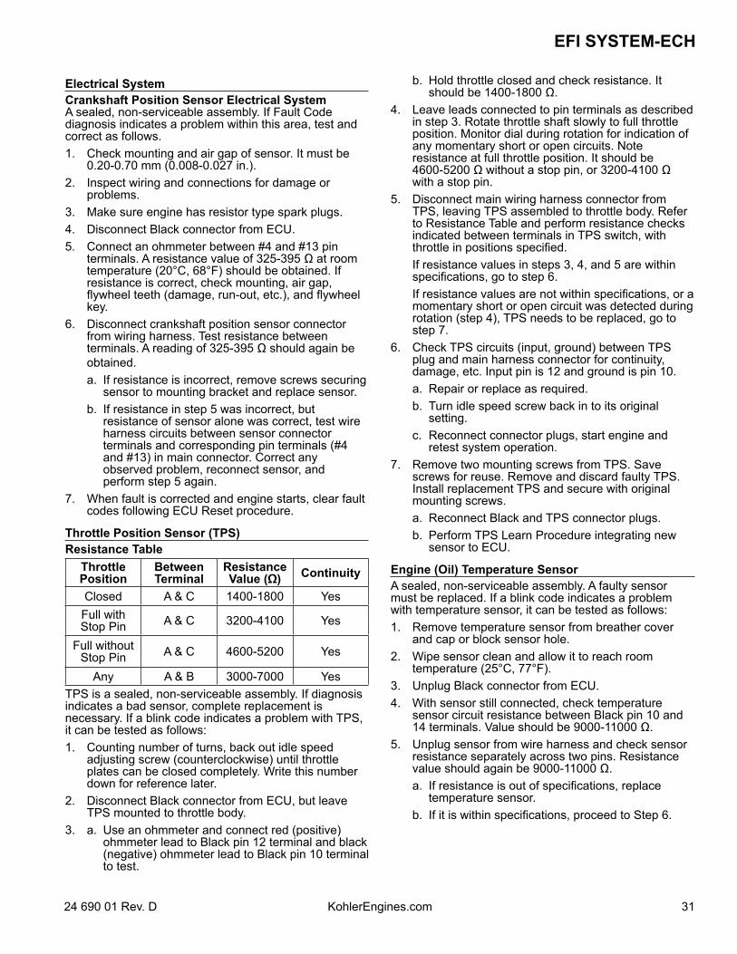
3124 690 01 Rev. D KohlerEngines.com
EFI SYSTEM-ECH
Electrical SystemCrankshaft Position Sensor Electrical SystemA sealed, non-serviceable assembly. If Fault Code diagnosis indicates a problem within this area, test and correct as follows.1. Check mounting and air gap of sensor. It must be
0.20-0.70 mm (0.008-0.027 in.).2. Inspect wiring and connections for damage or
problems.3. Make sure engine has resistor type spark plugs.4. Disconnect Black connector from ECU. 5. Connect an ohmmeter between #4 and #13 pin
terminals. A resistance value of 325-395 Ω at room temperature (20°C, 68°F) should be obtained. If resistance is correct, check mounting, air gap, flywheel teeth (damage, run-out, etc.), and flywheel key.
6. Disconnect crankshaft position sensor connector from wiring harness. Test resistance between terminals. A reading of 325-395 Ω should again be obtained.
a. If resistance is incorrect, remove screws securing sensor to mounting bracket and replace sensor.
b. If resistance in step 5 was incorrect, but resistance of sensor alone was correct, test wire harness circuits between sensor connector terminals and corresponding pin terminals (#4 and #13) in main connector. Correct any observed problem, reconnect sensor, and perform step 5 again.
7. When fault is corrected and engine starts, clear fault codes following ECU Reset procedure.
Throttle Position Sensor (TPS)Resistance Table
ThrottlePosition
BetweenTerminal
ResistanceValue (Ω) Continuity
Closed A & C 1400-1800 YesFull withStop Pin A & C 3200-4100 Yes
Full withoutStop Pin A & C 4600-5200 Yes
Any A & B 3000-7000 YesTPS is a sealed, non-serviceable assembly. If diagnosis indicates a bad sensor, complete replacement is necessary. If a blink code indicates a problem with TPS, it can be tested as follows:1. Counting number of turns, back out idle speed
adjusting screw (counterclockwise) until throttle plates can be closed completely. Write this number down for reference later.
2. Disconnect Black connector from ECU, but leave TPS mounted to throttle body.
3. a. Use an ohmmeter and connect red (positive) ohmmeter lead to Black pin 12 terminal and black (negative) ohmmeter lead to Black pin 10 terminal to test.
b. Hold throttle closed and check resistance. It should be 1400-1800 Ω.
4. Leave leads connected to pin terminals as described in step 3. Rotate throttle shaft slowly to full throttle position. Monitor dial during rotation for indication of any momentary short or open circuits. Note resistance at full throttle position. It should be 4600-5200 Ω without a stop pin, or 3200-4100 Ω with a stop pin.
5. Disconnect main wiring harness connector from TPS, leaving TPS assembled to throttle body. Refer to Resistance Table and perform resistance checks indicated between terminals in TPS switch, with throttle in positions specified.
If resistance values in steps 3, 4, and 5 are within specifications, go to step 6.
If resistance values are not within specifications, or a momentary short or open circuit was detected during rotation (step 4), TPS needs to be replaced, go to step 7.
6. Check TPS circuits (input, ground) between TPS plug and main harness connector for continuity, damage, etc. Input pin is 12 and ground is pin 10.
a. Repair or replace as required. b. Turn idle speed screw back in to its original
setting. c. Reconnect connector plugs, start engine and
retest system operation.7. Remove two mounting screws from TPS. Save
screws for reuse. Remove and discard faulty TPS. Install replacement TPS and secure with original mounting screws.
a. Reconnect Black and TPS connector plugs. b. Perform TPS Learn Procedure integrating new
sensor to ECU.
Engine (Oil) Temperature SensorA sealed, non-serviceable assembly. A faulty sensor must be replaced. If a blink code indicates a problem with temperature sensor, it can be tested as follows:1. Remove temperature sensor from breather cover
and cap or block sensor hole.2. Wipe sensor clean and allow it to reach room
temperature (25°C, 77°F).3. Unplug Black connector from ECU.4. With sensor still connected, check temperature
sensor circuit resistance between Black pin 10 and 14 terminals. Value should be 9000-11000 Ω.
5. Unplug sensor from wire harness and check sensor resistance separately across two pins. Resistance value should again be 9000-11000 Ω.
a. If resistance is out of specifications, replace temperature sensor.
b. If it is within specifications, proceed to Step 6.
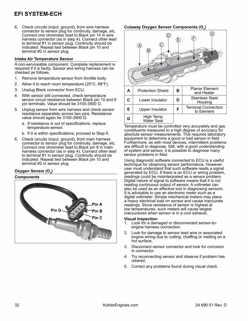
EFI SYSTEM-ECH
32 24 690 01 Rev. DKohlerEngines.com
6. Check circuits (input, ground), from wire harness connector to sensor plug for continuity, damage, etc. Connect one ohmmeter lead to Black pin 14 in wire harness connector (as in step 4). Connect other lead to terminal #1 in sensor plug. Continuity should be indicated. Repeat test between Black pin 10 and terminal #2 in sensor plug.
Intake Air Temperature SensorA non-serviceable component. Complete replacement is required if it is faulty. Sensor and wiring harness can be checked as follows.1. Remove temperature sensor from throttle body.2. Allow it to reach room temperature (20°C, 68°F).3. Unplug Black connector from ECU.4. With sensor still connected, check temperature
sensor circuit resistance between Black pin 10 and 8 pin terminals. Value should be 3100-3900 Ω.
5. Unplug sensor from wire harness and check sensor resistance separately across two pins. Resistance value should again be 3100-3900 Ω.
a. If resistance is out of specifications, replace temperature sensor.
b. If it is within specifications, proceed to Step 6.6. Check circuits (input, ground), from main harness
connector to sensor plug for continuity, damage, etc. Connect one ohmmeter lead to Black pin 8 in main harness connector (as in step 4). Connect other lead to terminal #1 in sensor plug. Continuity should be indicated. Repeat test between Black pin 10 and terminal #2 in sensor plug.
Oxygen Sensor (O2)Components
Pin D
Pin CPin BPin A
Cutaway Oxygen Sensor Components (O2)
AB
C
DE F
G
A Protection Shield B Planar Elementand Heater
C Lower Insulator D Stainless SteelHousing
E Upper Insulator F Terminal Connectionto Element
G High TempWater Seal
Temperature must be controlled very accurately and gas constituents measured to a high degree of accuracy for absolute sensor measurements. This requires laboratory equipment to determine a good or bad sensor in field. Furthermore, as with most devices, intermittent problems are difficult to diagnose. Still, with a good understanding of system and sensor, it is possible to diagnose many sensor problems in field.Using diagnostic software connected to ECU is a useful technique for observing sensor performance. However, user must understand that such software reads a signal generated by ECU. If there is an ECU or wiring problem, readings could be misinterpreted as a sensor problem. Digital nature of signal to software means that it is not reading continuous output of sensor. A voltmeter can also be used as an effective tool in diagnosing sensors. It is advisable to use an electronic meter such as a digital voltmeter. Simple mechanical meters may place a heavy electrical load on sensor and cause inaccurate readings. Since resistance of sensor is highest at low temperatures, such meters will cause largest inaccuracies when sensor is in a cool exhaust.Visual Inspection1. Look for a damaged or disconnected sensor-to-
engine harness connection.2. Look for damage to sensor lead wire or associated
engine wiring due to cutting, chaffing or melting on a hot surface.
3. Disconnect sensor connector and look for corrosion in connector.
4. Try reconnecting sensor and observe if problem has cleared.
5. Correct any problems found during visual check.
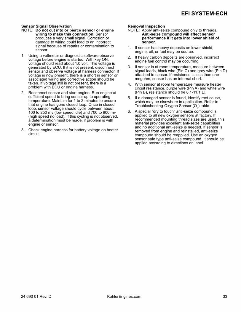
3324 690 01 Rev. D KohlerEngines.com
EFI SYSTEM-ECH
Sensor Signal ObservationNOTE: Do not cut into or pierce sensor or engine
wiring to make this connection. Sensor produces a very small signal. Corrosion or damage to wiring could lead to an incorrect signal because of repairs or contamination to sensor.
1. Using a voltmeter or diagnostic software observe voltage before engine is started. With key ON, voltage should read about 1.0 volt. This voltage is generated by ECU. If it is not present, disconnect sensor and observe voltage at harness connector. If voltage is now present, there is a short in sensor or associated wiring and corrective action should be taken. If voltage still is not present, there is a problem with ECU or engine harness.
2. Reconnect sensor and start engine. Run engine at sufficient speed to bring sensor up to operating temperature. Maintain for 1 to 2 minutes to ensure that engine has gone closed loop. Once in closed loop, sensor voltage should cycle between about 100 to 250 mv (low speed idle) and 700 to 900 mv (high speed no load). If this cycling is not observed, a determination must be made, if problem is with engine or sensor.
3. Check engine harness for battery voltage on heater circuit.
Removal InspectionNOTE: Apply anti-seize compound only to threads.
Anti-seize compound will affect sensor performance if it gets into lower shield of sensor.
1. If sensor has heavy deposits on lower shield, engine, oil, or fuel may be source.
2. If heavy carbon deposits are observed, incorrect engine fuel control may be occurring.
3. If sensor is at room temperature, measure between signal leads, black wire (Pin C) and grey wire (Pin D) attached to sensor. If resistance is less than one megohm, sensor has an internal short.
4. With sensor at room temperature measure heater circuit resistance, purple wire (Pin A) and white wire (Pin B), resistance should be 8.1-11.1 Ω.
5. If a damaged sensor is found, identify root cause, which may be elsewhere in application. Refer to Troubleshooting-Oxygen Sensor (O2) table.
6. A special "dry to touch" anti-seize compound is applied to all new oxygen sensors at factory. If recommended mounting thread sizes are used, this material provides excellent anti-seize capabilities and no additional anti-seize is needed. If sensor is removed from engine and reinstalled, anti-seize compound should be reapplied. Use an oxygen sensor safe type anti-seize compound. It should be applied according to directions on label.
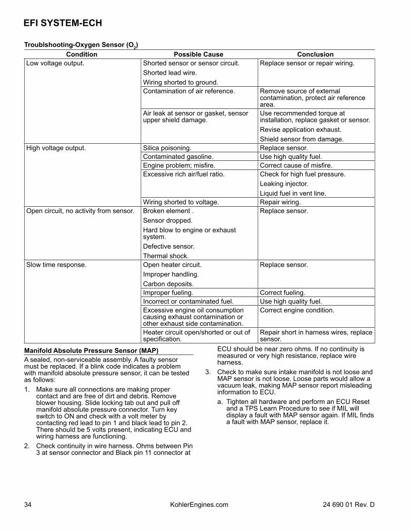
EFI SYSTEM-ECH
34 24 690 01 Rev. DKohlerEngines.com
Troublshooting-Oxygen Sensor (O2)Condition Possible Cause Conclusion
Low voltage output. Shorted sensor or sensor circuit.Shorted lead wire.Wiring shorted to ground.
Replace sensor or repair wiring.
Contamination of air reference. Remove source of external contamination, protect air reference area.
Air leak at sensor or gasket, sensor upper shield damage.
Use recommended torque at installation, replace gasket or sensor.Revise application exhaust.Shield sensor from damage.
High voltage output. Silica poisoning. Replace sensor.Contaminated gasoline. Use high quality fuel.Engine problem; misfire. Correct cause of misfire.Excessive rich air/fuel ratio. Check for high fuel pressure.
Leaking injector.Liquid fuel in vent line.
Wiring shorted to voltage. Repair wiring.Open circuit, no activity from sensor. Broken element .
Sensor dropped.Hard blow to engine or exhaust system.Defective sensor.Thermal shock.
Replace sensor.
Slow time response. Open heater circuit.Improper handling.Carbon deposits.
Replace sensor.
Improper fueling. Correct fueling.Incorrect or contaminated fuel. Use high quality fuel.Excessive engine oil consumption causing exhaust contamination or other exhaust side contamination.
Correct engine condition.
Heater circuit open/shorted or out of specification.
Repair short in harness wires, replace sensor.
Manifold Absolute Pressure Sensor (MAP)A sealed, non-serviceable assembly. A faulty sensor must be replaced. If a blink code indicates a problem with manifold absolute pressure sensor, it can be tested as follows:1. Make sure all connections are making proper
contact and are free of dirt and debris. Remove blower housing. Slide locking tab out and pull off manifold absolute pressure connector. Turn key switch to ON and check with a volt meter by contacting red lead to pin 1 and black lead to pin 2. There should be 5 volts present, indicating ECU and wiring harness are functioning.
2. Check continuity in wire harness. Ohms between Pin 3 at sensor connector and Black pin 11 connector at
ECU should be near zero ohms. If no continuity is measured or very high resistance, replace wire harness.
3. Check to make sure intake manifold is not loose and MAP sensor is not loose. Loose parts would allow a vacuum leak, making MAP sensor report misleading information to ECU.
a. Tighten all hardware and perform an ECU Reset and a TPS Learn Procedure to see if MIL will display a fault with MAP sensor again. If MIL finds a fault with MAP sensor, replace it.
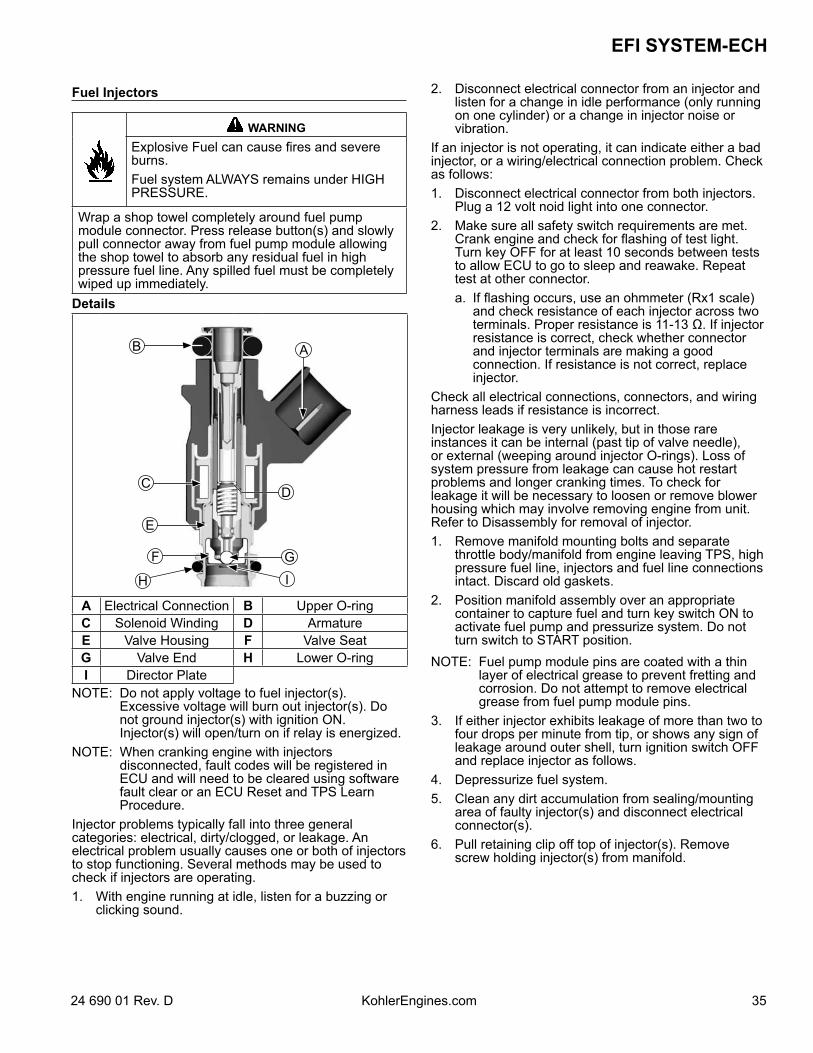
3524 690 01 Rev. D KohlerEngines.com
EFI SYSTEM-ECH
Fuel Injectors
WARNINGExplosive Fuel can cause fires and severe burns.Fuel system ALWAYS remains under HIGH PRESSURE.
Wrap a shop towel completely around fuel pump module connector. Press release button(s) and slowly pull connector away from fuel pump module allowing the shop towel to absorb any residual fuel in high pressure fuel line. Any spilled fuel must be completely wiped up immediately.
Details
AB
C
E
F
H I
G
D
A Electrical Connection B Upper O-ringC Solenoid Winding D ArmatureE Valve Housing F Valve SeatG Valve End H Lower O-ringI Director Plate
NOTE: Do not apply voltage to fuel injector(s). Excessive voltage will burn out injector(s). Do not ground injector(s) with ignition ON. Injector(s) will open/turn on if relay is energized.
NOTE: When cranking engine with injectors disconnected, fault codes will be registered in ECU and will need to be cleared using software fault clear or an ECU Reset and TPS Learn Procedure.
Injector problems typically fall into three general categories: electrical, dirty/clogged, or leakage. An electrical problem usually causes one or both of injectors to stop functioning. Several methods may be used to check if injectors are operating. 1. With engine running at idle, listen for a buzzing or
clicking sound.
2. Disconnect electrical connector from an injector and listen for a change in idle performance (only running on one cylinder) or a change in injector noise or vibration.
If an injector is not operating, it can indicate either a bad injector, or a wiring/electrical connection problem. Check as follows:1. Disconnect electrical connector from both injectors.
Plug a 12 volt noid light into one connector.2. Make sure all safety switch requirements are met.
Crank engine and check for flashing of test light. Turn key OFF for at least 10 seconds between tests to allow ECU to go to sleep and reawake. Repeat test at other connector.
a. If flashing occurs, use an ohmmeter (Rx1 scale) and check resistance of each injector across two terminals. Proper resistance is 11-13 Ω. If injector resistance is correct, check whether connector and injector terminals are making a good connection. If resistance is not correct, replace injector.
Check all electrical connections, connectors, and wiring harness leads if resistance is incorrect.Injector leakage is very unlikely, but in those rare instances it can be internal (past tip of valve needle), or external (weeping around injector O-rings). Loss of system pressure from leakage can cause hot restart problems and longer cranking times. To check for leakage it will be necessary to loosen or remove blower housing which may involve removing engine from unit. Refer to Disassembly for removal of injector.1. Remove manifold mounting bolts and separate
throttle body/manifold from engine leaving TPS, high pressure fuel line, injectors and fuel line connections intact. Discard old gaskets.
2. Position manifold assembly over an appropriate container to capture fuel and turn key switch ON to activate fuel pump and pressurize system. Do not turn switch to START position.
NOTE: Fuel pump module pins are coated with a thin layer of electrical grease to prevent fretting and corrosion. Do not attempt to remove electrical grease from fuel pump module pins.
3. If either injector exhibits leakage of more than two to four drops per minute from tip, or shows any sign of leakage around outer shell, turn ignition switch OFF and replace injector as follows.
4. Depressurize fuel system.5. Clean any dirt accumulation from sealing/mounting
area of faulty injector(s) and disconnect electrical connector(s).
6. Pull retaining clip off top of injector(s). Remove screw holding injector(s) from manifold.
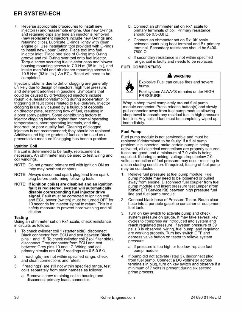
EFI SYSTEM-ECH
36 24 690 01 Rev. DKohlerEngines.com
7. Reverse appropriate procedures to install new injector(s) and reassemble engine. Use new O-rings and retaining clips any time an injector is removed (new replacement injectors include new O-rings and retaining clips). Lubricate O-rings lightly with clean engine oil. Use installation tool provided with O-rings to install new upper O-ring. Place tool into fuel injector inlet. Place one side of O-ring into O-ring groove and roll O-ring over tool onto fuel injector. Torque screw securing fuel injector caps and blower housing mounting screws to 7.3 N·m (65 in. lb.), and intake manifold and air cleaner mounting screws to 10.5 N·m (93 in. lb.). An ECU Reset will need to be completed.
Injector problems due to dirt or clogging are generally unlikely due to design of injectors, high fuel pressure, and detergent additives in gasoline. Symptoms that could be caused by dirty/clogged injectors include rough idle, hesitation/stumbling during acceleration, or triggering of fault codes related to fuel delivery. Injector clogging is usually caused by a buildup of deposits on director plate, restricting flow of fuel, resulting in a poor spray pattern. Some contributing factors to injector clogging include higher than normal operating temperatures, short operating intervals, and dirty, incorrect, or poor quality fuel. Cleaning of clogged injectors is not recommended; they should be replaced. Additives and higher grades of fuel can be used as a preventative measure if clogging has been a problem.
Ignition CoilIf a coil is determined to be faulty, replacement is necessary. An ohmmeter may be used to test wiring and coil windings.NOTE: Do not ground primary coil with ignition ON as
they may overheat or spark.NOTE: Always disconnect spark plug lead from spark
plug before performing following tests.NOTE: If ignition coil(s) are disabled and an ignition
fault is registered, system will automatically disable corresponding fuel injector drive signal. Fault must be corrected to ignition coil and ECU power (switch) must be turned OFF for 10 seconds for injector signal to return. This is a safety measure to prevent bore washing and oil dilution.
TestingUsing an ohmmeter set on Rx1 scale, check resistance in circuits as follows:1. To check cylinder coil 1 (starter side), disconnect
Black connector from ECU and test between Black pins 1 and 15. To check cylinder coil 2 (oil filter side), disconnect Grey connector from ECU and test between Grey pins 10 and 17. Wiring and coil primary circuits are OK if readings are 0.5-0.8 Ω.
2. If reading(s) are not within specified range, check and clean connections and retest.
3. If reading(s) are still not within specified range, test coils separately from main harness as follows:
a. Remove screw retaining coil to housing and disconnect primary leads connector.
b. Connect an ohmmeter set on Rx1 scale to primary terminals of coil. Primary resistance should be 0.5-0.8 Ω.
c. Connect an ohmmeter set on Rx10K scale between spark plug boot terminal and B+ primary terminal. Secondary resistance should be 6400-7800 Ω.
d. If secondary resistance is not within specified range, coil is faulty and needs to be replaced.
FUEL COMPONENTS
WARNINGExplosive Fuel can cause fires and severe burns.Fuel system ALWAYS remains under HIGH PRESSURE.
Wrap a shop towel completely around fuel pump module connector. Press release button(s) and slowly pull connector away from fuel pump module allowing shop towel to absorb any residual fuel in high pressure fuel line. Any spilled fuel must be completely wiped up immediately.
Fuel PumpFuel pump module is not serviceable and must be replaced if determined to be faulty. If a fuel pump problem is suspected, make certain pump is being activated, all electrical connections are properly secured, fuses are good, and a minimum of 7.0 volts is being supplied. If during cranking, voltage drops below 7.0 volts, a reduction of fuel pressure may occur resulting in a lean starting condition. If required, testing of fuel pump may be conducted.1. Relieve fuel pressure at fuel pump module. Fuel
pump module may need to be loosened or pulled away from engine. Disconnect fuel coupler from fuel pump module and insert pressure test jumper (from Kohler EFI Service Kit) between high pressure fuel line and fuel pump module.
2. Connect black hose of Pressure Tester. Route clear hose into a portable gasoline container or equipment fuel tank.
3. Turn on key switch to activate pump and check system pressure on gauge. It may take several key cycles to compress air introduced into system and reach regulated pressure. If system pressure of 39 psi ± 3 is observed, wiring, fuel pump, and regulator are working properly. Turn key switch OFF and depress valve button on tester to relieve system pressure.
a. If pressure is too high or too low, replace fuel pump module.
4. If pump did not activate (step 3), disconnect plug from fuel pump. Connect a DC voltmeter across terminals in plug, turn on key switch and observe if a minimum of 7 volts is present during six second prime process.
3724 690 01 Rev. D KohlerEngines.com
EFI SYSTEM-ECH
5. If no voltage is observed, connect red lead of meter to red wire of plug and black lead to a good ground while key is still ON.
6. If voltage is between 7 and 14, turn key switch OFF and connect an ohmmeter between terminals on pump to check for continuity.
a. If there was no continuity between pump terminals, replace fuel pump. b. If voltage was below 7, test wiring harness.7. If voltage at plug was good, and there was continuity across pump terminals, reconnect plug to pump, making
sure you have a good connection. Turn on key switch and listen for pump to activate. a. If pump starts, repeat steps 2 and 3 to verify correct pressure. b. If pump still does not operate, replace it.
High Pressure Fuel LineHigh pressure fuel line is mounted to intake manifold. No specific servicing is required unless operating conditions indicate that it needs replacement. Thoroughly clean area around all joints and relieve any pressure before starting any disassembly.Detach by removing two mounting screws, wire ties, and injector retaining clips. Purge Port and Vent Hose AssemblyNo specific servicing is required for vent hose assembly or purge port unless operating conditions indicate replacement is required. All components are serviced individually. Abrasion sleeves on hoses should be reused or replaced when servicing vent hoses. Please note vent hose routing and replicate after service or component replacement to prevent pinching or abrasion of vent hoses. Only Kohler replacement parts can be used because fitting is specific to system and must be maintained. Visit KohlerEngines.com for recommended Kohler replacement parts.
Throttle Body/Intake Manifold AssemblyNOTE: ECU Reset is required if throttle body is replaced.Throttle body is serviced as an assembly, with throttle shaft, TPS, throttle plate, and idle speed adjusting screw installed. Throttle shaft rotates on needle bearings (non-serviceable), capped with seals to prevent air leaks.TROUBLESHOOTING
Troubleshooting GuideCondition Possible Cause
Engine Starts Hard or Fails to Start
When Cold.
Fuel pump not running.Faulty spark plugs.Old/stale fuel.Incorrect fuel pressure.Crankshaft position sensor loose or faulty.TPS set incorrect (ECU Reset and TPS Initialitzation).TPS faulty.Engine temp sensor faulty.Faulty coils.Low system voltage.Faulty injectors.Faulty battery.Loose or corroded connections.
EFI SYSTEM-ECH
38 24 690 01 Rev. DKohlerEngines.com
Troubleshooting GuideCondition Possible Cause
Engine Starts Hard or Fails to Start
When Hot.
Faulty spark plugs.Fuel pump not running.Fuel pressure low.Insufficient fuel delivery.TPS set incorrect (ECU Reset and TPS Initialization).Crankshaft position sensor loose or faulty.TPS faulty.Engine temp sensor faulty.Faulty injectors.
Engine Stalls or Idles Roughly
(cold or warm).
Faulty spark plugs.Insufficient fuel delivery.TPS set incorrect.TPS faulty.Faulty engine temperature sensor.Faulty injectors.
Engine Misses, Hesitates, or Stalls
Under Load.
Fuel injector(s), fuel filter, fuel line, or fuel pick-up dirty/restricted.Dirty air cleaner.Insufficient fuel pressure or fuel deliveVacuum (intake air) leak.Improper governor setting, adjustment or operation.TPS faulty, mounting problem or TPS Initialization Procedure incorrect.Bad coil(s), spark plug(s), or wires.
Low Power
Faulty/malfunctioning ignition system.Dirty air filter.Insufficient fuel delivery.Improper governor adjustment.Plugged/restricted exhaust.One injector not working.Basic engine problem exists.TPS faulty or mounting exists.Throttle plate in throttle body not fully opening to WOT stop (if equipped).
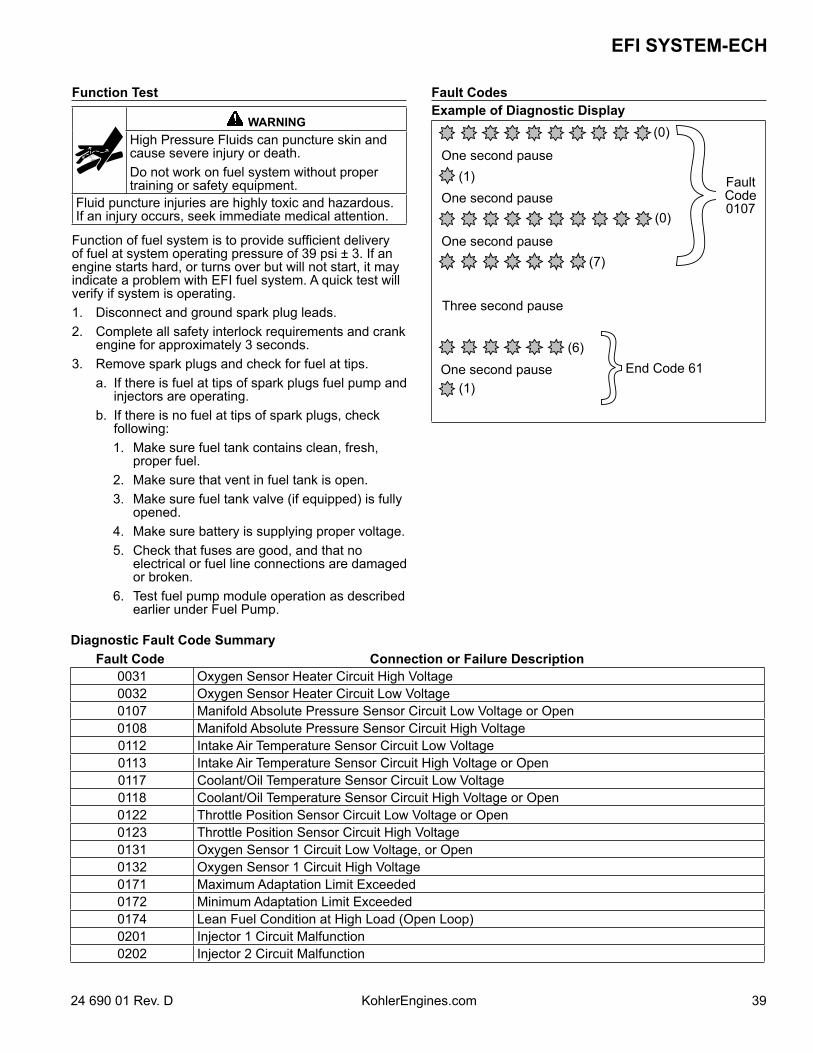
3924 690 01 Rev. D KohlerEngines.com
EFI SYSTEM-ECH
Function Test
WARNINGHigh Pressure Fluids can puncture skin and cause severe injury or death.Do not work on fuel system without proper training or safety equipment.
Fluid puncture injuries are highly toxic and hazardous. If an injury occurs, seek immediate medical attention.
Function of fuel system is to provide sufficient delivery of fuel at system operating pressure of 39 psi ± 3. If an engine starts hard, or turns over but will not start, it may indicate a problem with EFI fuel system. A quick test will verify if system is operating.1. Disconnect and ground spark plug leads. 2. Complete all safety interlock requirements and crank
engine for approximately 3 seconds.3. Remove spark plugs and check for fuel at tips. a. If there is fuel at tips of spark plugs fuel pump and
injectors are operating. b. If there is no fuel at tips of spark plugs, check
following: 1. Make sure fuel tank contains clean, fresh,
proper fuel. 2. Make sure that vent in fuel tank is open. 3. Make sure fuel tank valve (if equipped) is fully
opened. 4. Make sure battery is supplying proper voltage. 5. Check that fuses are good, and that no
electrical or fuel line connections are damaged or broken.
6. Test fuel pump module operation as described earlier under Fuel Pump.
Fault CodesExample of Diagnostic Display
One second pause
One second pause
One second pause
One second pause
Three second pause
(0)
(0)
(7)
(6)
(1)
(1)
End Code 61
FaultCode0107
Diagnostic Fault Code SummaryFault Code Connection or Failure Description
0031 Oxygen Sensor Heater Circuit High Voltage0032 Oxygen Sensor Heater Circuit Low Voltage0107 Manifold Absolute Pressure Sensor Circuit Low Voltage or Open0108 Manifold Absolute Pressure Sensor Circuit High Voltage0112 Intake Air Temperature Sensor Circuit Low Voltage0113 Intake Air Temperature Sensor Circuit High Voltage or Open0117 Coolant/Oil Temperature Sensor Circuit Low Voltage0118 Coolant/Oil Temperature Sensor Circuit High Voltage or Open0122 Throttle Position Sensor Circuit Low Voltage or Open0123 Throttle Position Sensor Circuit High Voltage0131 Oxygen Sensor 1 Circuit Low Voltage, or Open0132 Oxygen Sensor 1 Circuit High Voltage0171 Maximum Adaptation Limit Exceeded0172 Minimum Adaptation Limit Exceeded0174 Lean Fuel Condition at High Load (Open Loop)0201 Injector 1 Circuit Malfunction0202 Injector 2 Circuit Malfunction
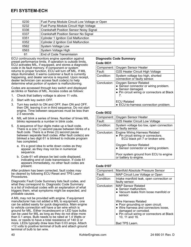
EFI SYSTEM-ECH
40 24 690 01 Rev. DKohlerEngines.com
0230 Fuel Pump Module Circuit Low Voltage or Open0232 Fuel Pump Module Circuit High Voltage0336 Crankshaft Position Sensor Noisy Signal0337 Crankshaft Position Sensor No Signal0351 Cylinder 1 Ignition Coil Malfunction0352 Cylinder 2 Ignition Coil Malfunction0562 System Voltage Low0563 System Voltage High
61 End of Code TransmissionECU continuously monitors engine operation against preset performance limits. If operation is outside limits, ECU activates MIL, if equipped, and stores a diagnostic code in its fault memory. If component or system returns to proper function, ECU will turn off MIL. If MIL stays illuminated, it warns customer a fault is currently happening, and dealer service is required. Upon receipt, dealer technician can access fault code(s) to help determine what portion of system is malfunctioning. Codes are accessed through key switch and displayed as blinks or flashes of MIL. Access codes as follows:1. Check that battery voltage is above 11 volts.2. Start with key switch OFF.3. Turn key switch to ON and OFF, then ON and OFF,
then ON, leaving it on in third sequence. Do not start engine. Time between sequences must be less than 2.5 seconds.
4. MIL will blink a series of times. Number of times MIL blinks represents a number in blink code.
5. A sequence of four digits make up a fault code. There is a one (1) second pause between blinks of a fault code. There is a three (3) second pause between separate fault codes. After fault code(s) are blinked a two digit 61 is blinked to indicate program has completed.
a. It’s a good idea to write down codes as they appear, as they may not be in numerical sequence.
b. Code 61 will always be last code displayed, indicating end of code transmission. If code 61 appears immediately, no other fault codes are present.
After problem has been corrected, fault codes may be cleared by following ECU Reset and TPS Learn Procedures.Diagnostic Fault Code Summary lists fault codes, and what they correspond to. Diagnostic Code Summary is a list of individual codes with an explanation of what triggers them, what symptoms might be expected, and probable causes.A MIL may not be provided with engine. If equipment manufacturer has not added a MIL to equipment, one can be added easily for quick diagnostics. Main engine to vehicle connection will have a tan wire which is ground for MIL. Either incandescent or LED type bulbs can be used for MIL as long as they do not draw more than 0.1 amps. Bulb needs to be rated at 1.4 Watts or less, or needs to have a total resistance of 140 Ω or more. LEDs typically draw less than 0.03 amps. Attach +12 volts to positive terminal of bulb and attach ground terminal of bulb to tan wire.
Diagnostic Code SummaryCode 0031Component: Oxygen Sensor HeaterFault: O2S Heater Circuit High VoltageCondition: System voltage too high, shorted
connection or faulty sensor.Conclusion: Oxygen Sensor Related
Sensor connector or wiring problem. Sensor damaged. Pin circuit wiring or connectors at Black
7.
ECU Related ECU-to-harness connection problem.
Code 0032Component: Oxygen Sensor HeaterFault: O2S Heater Circuit Low VoltageCondition: System voltage too low, open connection
or faulty sensor.Conclusion: Engine Wiring Harness Related
Pin circuit wiring or connectors. ECU black pin 7 or broken wire.
Oxygen Sensor Related Sensor connector or wiring problem.
Poor system ground from ECU to engine or battery to engine.
Code 0107Component: Manifold Absolute Pressure SensorFault: MAP Circuit Low Voltage or OpenCondition: Intake manifold leak, open connection or
faulty sensor.Conclusion: MAP Sensor Related
Sensor malfunction. Vacuum leaks from loose manifold or
sensor.
Wire Harness Related Poor grounding or open circuit. Wire harness and connectors loose,
damaged or corroded. Pin circuit wiring or connectors at Black
10, 11 and 16.
Bad TPS Learn.
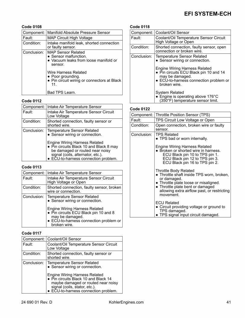
4124 690 01 Rev. D KohlerEngines.com
EFI SYSTEM-ECH
Code 0108Component: Manifold Absolute Pressure SensorFault: MAP Circuit High VoltageCondition: Intake manifold leak, shorted connection
or faulty sensor.Conclusion: MAP Sensor Related
Sensor malfunction. Vacuum leaks from loose manifold or
sensor.
Wire Harness Related Poor grounding. Pin circuit wiring or connectors at Black
11.
Bad TPS Learn.
Code 0112Component: Intake Air Temperature SensorFault: Intake Air Temperature Sensor Circuit
Low VoltageCondition: Shorted connection, faulty sensor or
shorted wire.Conclusion: Temperature Sensor Related
Sensor wiring or connection.
Engine Wiring Harness Related Pin circuits Black 10 and Black 8 may
be damaged or routed near noisy signal (coils, alternator, etc.).
ECU-to-harness connection problem.
Code 0113Component: Intake Air Temperature SensorFault: Intake Air Temperature Sensor Circuit
High Voltage or OpenCondition: Shorted connection, faulty sensor, broken
wire or connection.Conclusion: Temperature Sensor Related
Sensor wiring or connection.
Engine Wiring Harness Related Pin circuits ECU Black pin 10 and 8
may be damaged. ECU-to-harness connection problem or
broken wire.
Code 0117Component: Coolant/Oil SensorFault: Coolant/Oil Temperature Sensor Circuit
Low VoltageCondition: Shorted connection, faulty sensor or
shorted wire.Conclusion: Temperature Sensor Related
Sensor wiring or connection.
Engine Wiring Harness Related Pin circuits Black 10 and Black 14
maybe damaged or routed near noisy signal (coils, stator, etc.).
ECU-to-harness connection problem.
Code 0118Component: Coolant/Oil SensorFault: Coolant/Oil Temperature Sensor Circuit
High Voltage or OpenCondition: Shorted connection, faulty sensor, open
connection or broken wire.Conclusion: Temperature Sensor Related
Sensor wiring or connection.
Engine Wiring Harness Related Pin circuits ECU Black pin 10 and 14
may be damaged. ECU-to-harness connection problem or
broken wire.
System Related Engine is operating above 176°C
(350°F) temperature sensor limit.
Code 0122Component: Throttle Position Sensor (TPS)Fault: TPS Circuit Low Voltage or OpenCondition: Open connection, broken wire or faulty
sensor.Conclusion: TPS Related
TPS bad or worn internally.
Engine Wiring Harness Related Broken or shorted wire in harness. ECU Black pin 10 to TPS pin 1. ECU Black pin 12 to TPS pin 3. ECU Black pin 16 to TPS pin 2.
Throttle Body Related Throttle shaft inside TPS worn, broken,
or damaged. Throttle plate loose or misaligned. Throttle plate bent or damaged
allowing extra airflow past, or restricting movement.
ECU Related Circuit providing voltage or ground to
TPS damaged. TPS signal input circuit damaged.
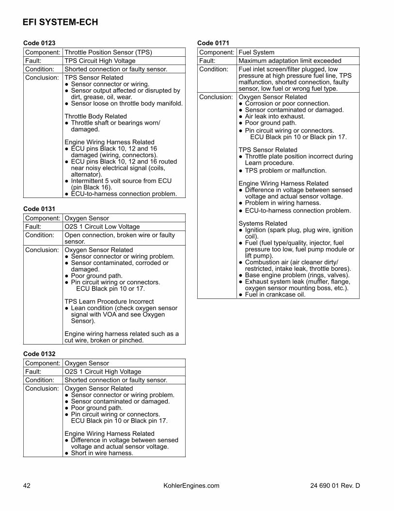
EFI SYSTEM-ECH
42 24 690 01 Rev. DKohlerEngines.com
Code 0123Component: Throttle Position Sensor (TPS)Fault: TPS Circuit High VoltageCondition: Shorted connection or faulty sensor.Conclusion: TPS Sensor Related
Sensor connector or wiring. Sensor output affected or disrupted by
dirt, grease, oil, wear. Sensor loose on throttle body manifold.
Throttle Body Related Throttle shaft or bearings worn/
damaged.
Engine Wiring Harness Related ECU pins Black 10, 12 and 16
damaged (wiring, connectors). ECU pins Black 10, 12 and 16 routed
near noisy electrical signal (coils, alternator).
Intermittent 5 volt source from ECU (pin Black 16).
ECU-to-harness connection problem.
Code 0131Component: Oxygen SensorFault: O2S 1 Circuit Low VoltageCondition: Open connection, broken wire or faulty
sensor.Conclusion: Oxygen Sensor Related
Sensor connector or wiring problem. Sensor contaminated, corroded or
damaged. Poor ground path. Pin circuit wiring or connectors. ECU Black pin 10 or 17.
TPS Learn Procedure Incorrect Lean condition (check oxygen sensor
signal with VOA and see Oxygen Sensor).
Engine wiring harness related such as a cut wire, broken or pinched.
Code 0132Component: Oxygen SensorFault: O2S 1 Circuit High VoltageCondition: Shorted connection or faulty sensor.Conclusion: Oxygen Sensor Related
Sensor connector or wiring problem. Sensor contaminated or damaged. Poor ground path. Pin circuit wiring or connectors. ECU Black pin 10 or Black pin 17.
Engine Wiring Harness Related Difference in voltage between sensed
voltage and actual sensor voltage. Short in wire harness.
Code 0171Component: Fuel SystemFault: Maximum adaptation limit exceededCondition: Fuel inlet screen/filter plugged, low
pressure at high pressure fuel line, TPS malfunction, shorted connection, faulty sensor, low fuel or wrong fuel type.
Conclusion: Oxygen Sensor Related Corrosion or poor connection. Sensor contaminated or damaged. Air leak into exhaust. Poor ground path. Pin circuit wiring or connectors. ECU Black pin 10 or Black pin 17.
TPS Sensor Related Throttle plate position incorrect during
Learn procedure. TPS problem or malfunction.
Engine Wiring Harness Related Difference in voltage between sensed
voltage and actual sensor voltage. Problem in wiring harness. ECU-to-harness connection problem.
Systems Related Ignition (spark plug, plug wire, ignition
coil). Fuel (fuel type/quality, injector, fuel
pressure too low, fuel pump module or lift pump).
Combustion air (air cleaner dirty/restricted, intake leak, throttle bores).
Base engine problem (rings, valves). Exhaust system leak (muffler, flange,
oxygen sensor mounting boss, etc.). Fuel in crankcase oil.
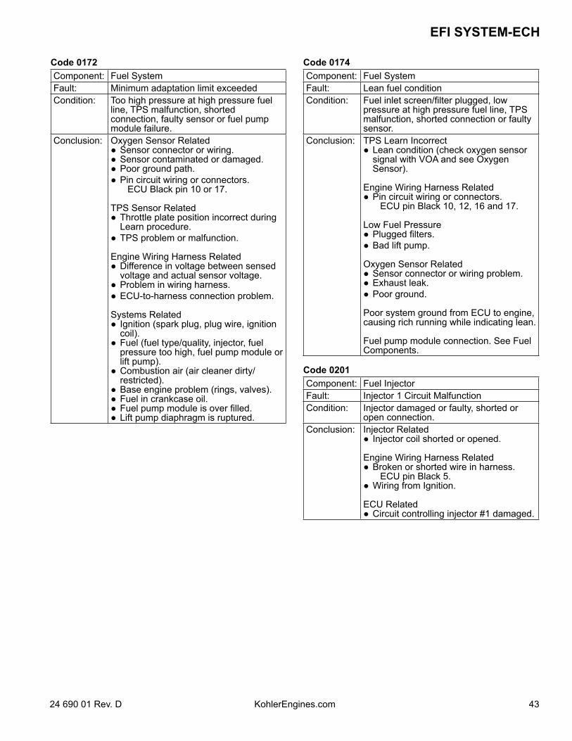
4324 690 01 Rev. D KohlerEngines.com
EFI SYSTEM-ECH
Code 0172Component: Fuel SystemFault: Minimum adaptation limit exceededCondition: Too high pressure at high pressure fuel
line, TPS malfunction, shorted connection, faulty sensor or fuel pump module failure.
Conclusion: Oxygen Sensor Related Sensor connector or wiring. Sensor contaminated or damaged. Poor ground path. Pin circuit wiring or connectors. ECU Black pin 10 or 17.
TPS Sensor Related Throttle plate position incorrect during
Learn procedure. TPS problem or malfunction.
Engine Wiring Harness Related Difference in voltage between sensed
voltage and actual sensor voltage. Problem in wiring harness. ECU-to-harness connection problem.
Systems Related Ignition (spark plug, plug wire, ignition
coil). Fuel (fuel type/quality, injector, fuel
pressure too high, fuel pump module or lift pump).
Combustion air (air cleaner dirty/restricted).
Base engine problem (rings, valves). Fuel in crankcase oil. Fuel pump module is over filled. Lift pump diaphragm is ruptured.
Code 0174Component: Fuel SystemFault: Lean fuel conditionCondition: Fuel inlet screen/filter plugged, low
pressure at high pressure fuel line, TPS malfunction, shorted connection or faulty sensor.
Conclusion: TPS Learn Incorrect Lean condition (check oxygen sensor
signal with VOA and see Oxygen Sensor).
Engine Wiring Harness Related Pin circuit wiring or connectors. ECU pin Black 10, 12, 16 and 17.
Low Fuel Pressure Plugged filters. Bad lift pump.
Oxygen Sensor Related Sensor connector or wiring problem. Exhaust leak. Poor ground.
Poor system ground from ECU to engine, causing rich running while indicating lean.
Fuel pump module connection. See Fuel Components.
Code 0201Component: Fuel InjectorFault: Injector 1 Circuit MalfunctionCondition: Injector damaged or faulty, shorted or
open connection.Conclusion: Injector Related
Injector coil shorted or opened.
Engine Wiring Harness Related Broken or shorted wire in harness. ECU pin Black 5. Wiring from Ignition.
ECU Related Circuit controlling injector #1 damaged.
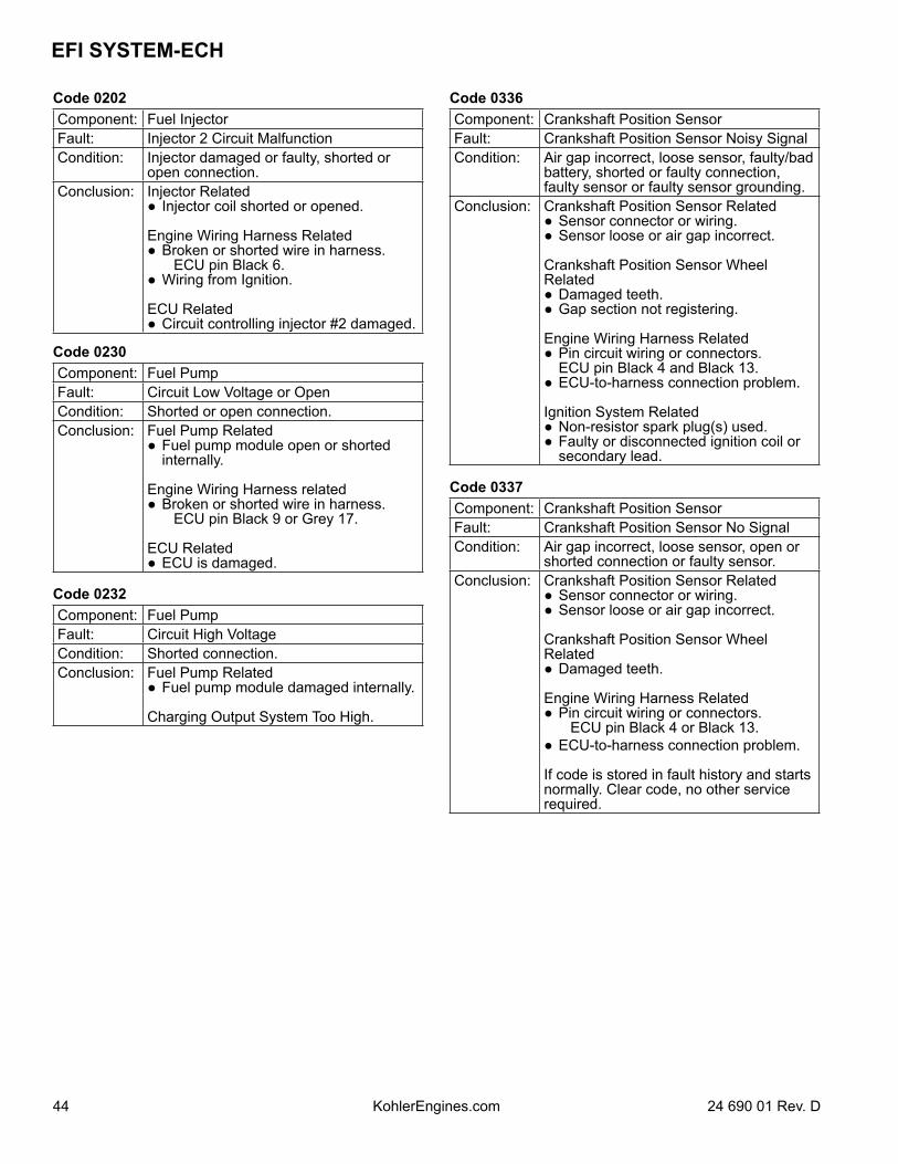
EFI SYSTEM-ECH
44 24 690 01 Rev. DKohlerEngines.com
Code 0202Component: Fuel InjectorFault: Injector 2 Circuit MalfunctionCondition: Injector damaged or faulty, shorted or
open connection.Conclusion: Injector Related
Injector coil shorted or opened.
Engine Wiring Harness Related Broken or shorted wire in harness. ECU pin Black 6. Wiring from Ignition.
ECU Related Circuit controlling injector #2 damaged.
Code 0230Component: Fuel PumpFault: Circuit Low Voltage or OpenCondition: Shorted or open connection.Conclusion: Fuel Pump Related
Fuel pump module open or shorted internally.
Engine Wiring Harness related Broken or shorted wire in harness. ECU pin Black 9 or Grey 17.
ECU Related ECU is damaged.
Code 0232Component: Fuel PumpFault: Circuit High VoltageCondition: Shorted connection.Conclusion: Fuel Pump Related
Fuel pump module damaged internally.
Charging Output System Too High.
Code 0336Component: Crankshaft Position SensorFault: Crankshaft Position Sensor Noisy SignalCondition: Air gap incorrect, loose sensor, faulty/bad
battery, shorted or faulty connection, faulty sensor or faulty sensor grounding.
Conclusion: Crankshaft Position Sensor Related Sensor connector or wiring. Sensor loose or air gap incorrect.
Crankshaft Position Sensor Wheel Related Damaged teeth. Gap section not registering.
Engine Wiring Harness Related Pin circuit wiring or connectors. ECU pin Black 4 and Black 13. ECU-to-harness connection problem.
Ignition System Related Non-resistor spark plug(s) used. Faulty or disconnected ignition coil or
secondary lead.
Code 0337Component: Crankshaft Position SensorFault: Crankshaft Position Sensor No SignalCondition: Air gap incorrect, loose sensor, open or
shorted connection or faulty sensor.Conclusion: Crankshaft Position Sensor Related
Sensor connector or wiring. Sensor loose or air gap incorrect.
Crankshaft Position Sensor Wheel Related Damaged teeth.
Engine Wiring Harness Related Pin circuit wiring or connectors. ECU pin Black 4 or Black 13. ECU-to-harness connection problem.
If code is stored in fault history and starts normally. Clear code, no other service required.
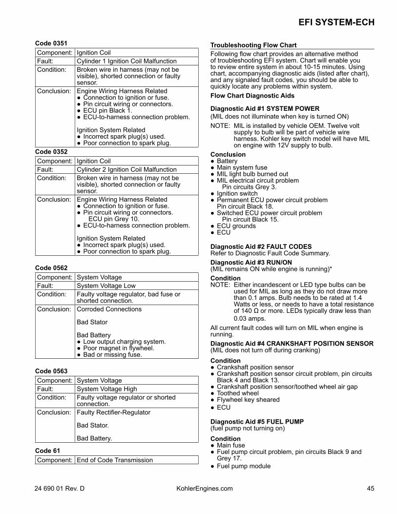
4524 690 01 Rev. D KohlerEngines.com
EFI SYSTEM-ECH
Code 0351Component: Ignition CoilFault: Cylinder 1 Ignition Coil MalfunctionCondition: Broken wire in harness (may not be
visible), shorted connection or faulty sensor.
Conclusion: Engine Wiring Harness Related Connection to ignition or fuse. Pin circuit wiring or connectors. ECU pin Black 1. ECU-to-harness connection problem.
Ignition System Related Incorrect spark plug(s) used. Poor connection to spark plug.
Code 0352Component: Ignition CoilFault: Cylinder 2 Ignition Coil MalfunctionCondition: Broken wire in harness (may not be
visible), shorted connection or faulty sensor.
Conclusion: Engine Wiring Harness Related Connection to ignition or fuse. Pin circuit wiring or connectors. ECU pin Grey 10. ECU-to-harness connection problem.
Ignition System Related Incorrect spark plug(s) used. Poor connection to spark plug.
Code 0562Component: System VoltageFault: System Voltage LowCondition: Faulty voltage regulator, bad fuse or
shorted connection.Conclusion: Corroded Connections
Bad Stator
Bad Battery Low output charging system. Poor magnet in flywheel. Bad or missing fuse.
Code 0563Component: System VoltageFault: System Voltage HighCondition: Faulty voltage regulator or shorted
connection.Conclusion: Faulty Rectifier-Regulator
Bad Stator.
Bad Battery.
Code 61Component: End of Code Transmission
Troubleshooting Flow ChartFollowing flow chart provides an alternative method of troubleshooting EFI system. Chart will enable you to review entire system in about 10-15 minutes. Using chart, accompanying diagnostic aids (listed after chart), and any signaled fault codes, you should be able to quickly locate any problems within system.Flow Chart Diagnostic Aids
Diagnostic Aid #1 SYSTEM POWER(MIL does not illuminate when key is turned ON)NOTE: MIL is installed by vehicle OEM. Twelve volt
supply to bulb will be part of vehicle wire harness. Kohler key switch model will have MIL on engine with 12V supply to bulb.
Conclusion Battery Main system fuse MIL light bulb burned out MIL electrical circuit problem Pin circuits Grey 3. Ignition switch Permanent ECU power circuit problem Pin circuit Black 18. Switched ECU power circuit problem Pin circuit Black 15. ECU grounds ECU
Diagnostic Aid #2 FAULT CODESRefer to Diagnostic Fault Code Summary.Diagnostic Aid #3 RUN/ON(MIL remains ON while engine is running)*ConditionNOTE: Either incandescent or LED type bulbs can be
used for MIL as long as they do not draw more than 0.1 amps. Bulb needs to be rated at 1.4 Watts or less, or needs to have a total resistance of 140 Ω or more. LEDs typically draw less than 0.03 amps.
All current fault codes will turn on MIL when engine is running.Diagnostic Aid #4 CRANKSHAFT POSITION SENSOR(MIL does not turn off during cranking)Condition Crankshaft position sensor Crankshaft position sensor circuit problem, pin circuits
Black 4 and Black 13. Crankshaft position sensor/toothed wheel air gap Toothed wheel Flywheel key sheared ECU
Diagnostic Aid #5 FUEL PUMP(fuel pump not turning on)Condition Main fuse Fuel pump circuit problem, pin circuits Black 9 and
Grey 17. Fuel pump module
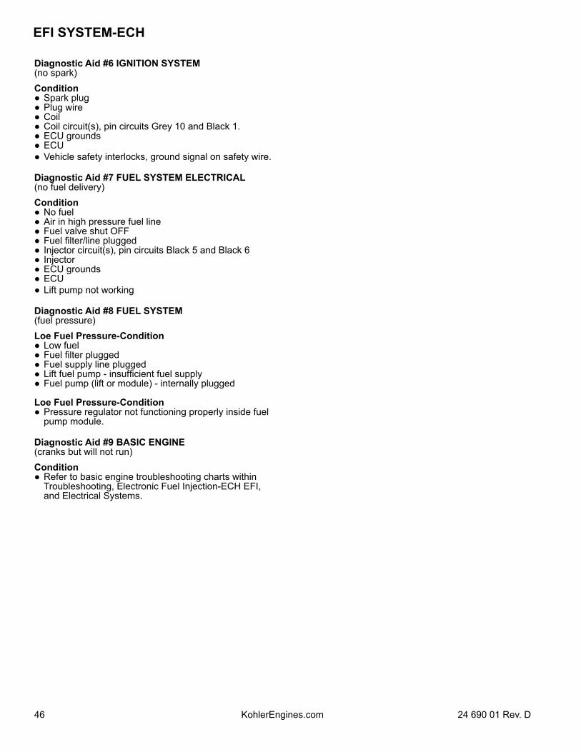
EFI SYSTEM-ECH
46 24 690 01 Rev. DKohlerEngines.com
Diagnostic Aid #6 IGNITION SYSTEM(no spark)Condition Spark plug Plug wire Coil Coil circuit(s), pin circuits Grey 10 and Black 1. ECU grounds ECU Vehicle safety interlocks, ground signal on safety wire.
Diagnostic Aid #7 FUEL SYSTEM ELECTRICAL(no fuel delivery)Condition No fuel Air in high pressure fuel line Fuel valve shut OFF Fuel filter/line plugged Injector circuit(s), pin circuits Black 5 and Black 6 Injector ECU grounds ECU Lift pump not working
Diagnostic Aid #8 FUEL SYSTEM(fuel pressure)Loe Fuel Pressure-Condition Low fuel Fuel filter plugged Fuel supply line plugged Lift fuel pump - insufficient fuel supply Fuel pump (lift or module) - internally plugged
Loe Fuel Pressure-Condition Pressure regulator not functioning properly inside fuel
pump module.
Diagnostic Aid #9 BASIC ENGINE(cranks but will not run)Condition Refer to basic engine troubleshooting charts within
Troubleshooting, Electronic Fuel Injection-ECH EFI, and Electrical Systems.
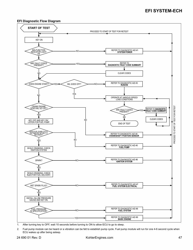
4724 690 01 Rev. D KohlerEngines.com
EFI SYSTEM-ECH
EFI Diagnostic Flow Diagram
START OF TEST
KEY ON
MALFUNCTION INDICATOR LIGHT
ON
ARE FAULT CODES PRESENT?
NO
DOES ENGINE START?
NO
CRANK ENGINE. DOES MIL GO OFF?
YES
KEY OFF AND KEY ON1. LISTEN FOR FUEL PUMP.
DOES FUEL PUMP CYCLE ON THEN OFF AFTER 1–2
SECONDS2?
YES
WHILE CRANKING, CHECK IGNITION SYSTEM
SPARK?
YES
WHILE CRANKING, CHECK INJECTOR FUEL DELIVERY.
WET SPARK PLUG?
YES
INSTALL IN-LINE PRESSURE GAUGE AND KEY ON.
FUEL PRESSURE IN SPECIFICATION?
NO
YES
YES MIL GOES OFF?
YES
NO
NO
NO
NO
NO
YES
REFER TO DIAGNOSTIC AID #1 SYSTEM POWER
REFER TO DIAGNOSTIC FAULT CODE SUMMARY
CLEAR CODES
NO REFER TO DIAGNOSTIC AID #3 RUN/ON
OPERATE AT VARIOUS SPEED/LOAD CONDITIONS
ARE FAULT CODES PRESENT?
NO
END OF TEST
REFER TO DIAGNOSTIC AID #4 CRANKSHAFT POSITION SENSOR
REFER TO DIAGNOSTIC AID #5 FUEL PUMP
REFER TO DIAGNOSTIC AID #6 IGNITION SYSTEM
REFER TO DIAGNOSTIC AID #7 FUEL SYSTEM ELECTRICAL
REFER TO DIAGNOSTIC AID #8 FUEL SYSTEM
REFER TO DIAGNOSTIC AID #9 BASIC ENGINE
YES REFER TO DIAGNOSTIC FAULT CODE SUMMARY
CLEAR CODES
PROC
EED
TO S
TART
OF
TEST
FOR
RET
EST
PROCEED TO START OF TEST FOR RETEST
1. After turning key to OFF, wait 10 seconds before turning to ON to allow ECU to go to sleep.
2. Fuel pump module can be heard or a vibration can be felt to establish pump cycle. Fuel pump module will run for one 4-6 second cycle when ECU wakes up after being asleep.
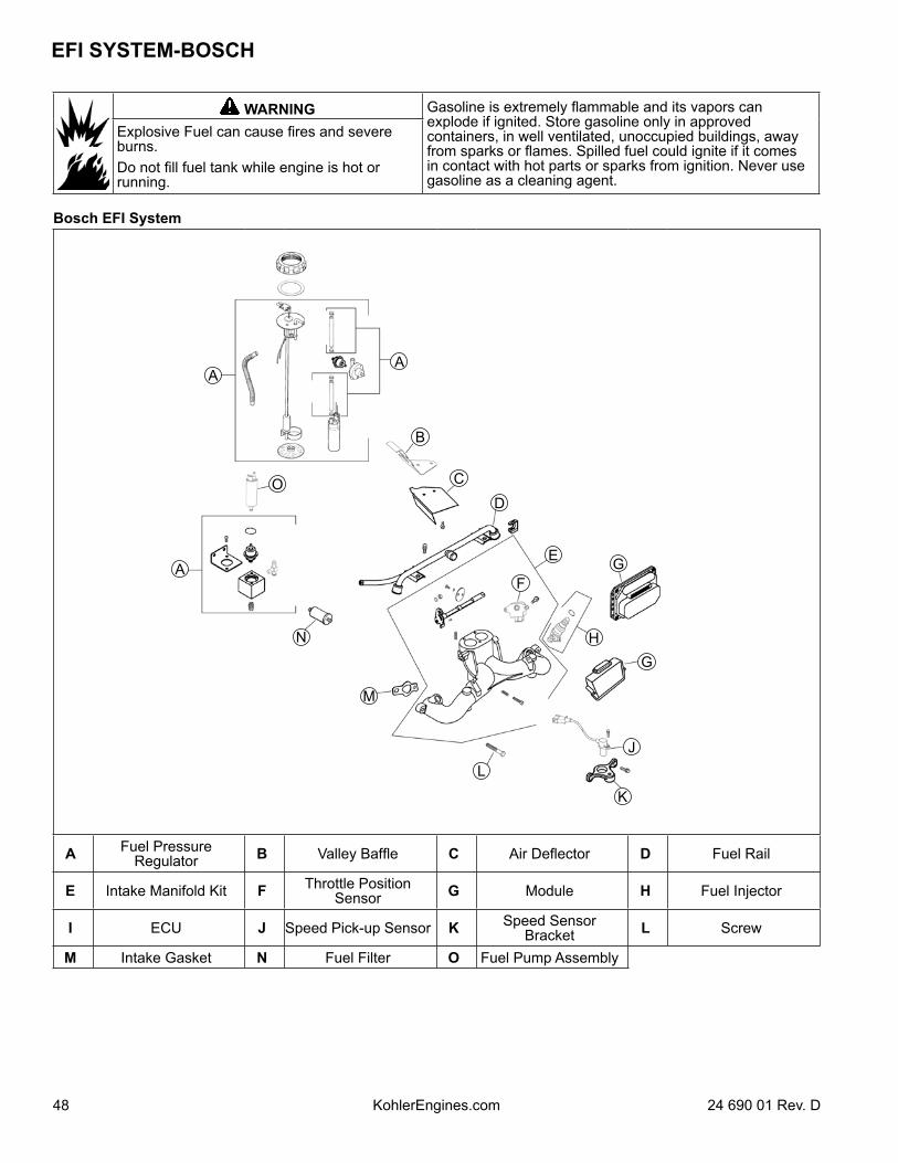
EFI SYSTEM-BOSCH
48 24 690 01 Rev. DKohlerEngines.com
WARNING Gasoline is extremely flammable and its vapors can explode if ignited. Store gasoline only in approved containers, in well ventilated, unoccupied buildings, away from sparks or flames. Spilled fuel could ignite if it comes in contact with hot parts or sparks from ignition. Never use gasoline as a cleaning agent.
Explosive Fuel can cause fires and severe burns.Do not fill fuel tank while engine is hot or running.
Bosch EFI System
AA
O
A
N
M
L
K
J
GH
GE
F
D
C
B
A Fuel Pressure Regulator B Valley Baffle C Air Deflector D Fuel Rail
E Intake Manifold Kit F Throttle Position Sensor G Module H Fuel Injector
I ECU J Speed Pick-up Sensor K Speed Sensor Bracket L Screw
M Intake Gasket N Fuel Filter O Fuel Pump Assembly
4924 690 01 Rev. D KohlerEngines.com
EFI SYSTEM-BOSCH
Typical electronic fuel injection (EFI) system and related components include: Fuel tank and valve. Fuel pump. Fuel filter. Fuel rail. Fuel line(s). Fuel injectors. Fuel pressure regulator. Throttle body/intake manifold. Electronic control unit (ECU). Ignition coils. Engine (oil) temperature sensor. Throttle position sensor (TPS). Speed sensor. Crankshaft position sensor. Oxygen sensor. Wire harness assembly & affiliated wiring. Malfunction indicator light (MIL). Intake air temperature sensor.
FUEL RECOMMENDATIONSRefer to Maintenance.
FUEL LINELow permeation fuel line must be installed on all Kohler Co. engines to maintain EPA and CARB regulatory compliance.
OperationNOTE: When performing voltage or continuity tests,
avoid putting excessive pressure on or against connector pins. Flat pin probes are recommended for testing to avoid spreading or bending terminals.
EFI system is designed to provide peak engine performance with optimum fuel efficiency and lowest possible emissions. Ignition and injection functions are electronically controlled, monitored and continually corrected during operation to maintain ideal air/fuel ratio. Central component of system is Engine Control Unit (ECU) which manages system operation, determining best combination of fuel mixture and ignition timing for current operating conditions. An electric fuel pump is used to move fuel from tank through fuel line and in-line fuel filter. A fuel pressure regulator maintains a system operating pressure of 39 psi and returns any excess fuel to tank. At engine, fuel is fed through fuel rail and into injectors, which inject it into intake ports. ECU controls amount of fuel by varying length of time that injectors are “ON.” This can range from 1.5-8.0 milliseconds depending on fuel requirements. Controlled injection of fuel occurs each crankshaft revolution, or twice for each 4-stroke cycle. One-half total amount of fuel needed for one firing of a cylinder is injected during each injection. When intake valve opens, fuel/air mixture is drawn into combustion chamber, ignited, and burned.
ECU controls amount of fuel being injected and ignition timing by monitoring primary sensor signals for engine temperature, speed (RPM), and throttle position (load). These primary signals are compared to preprogrammed maps in ECU computer chip, and ECU adjusts fuel delivery to match mapped values. After engine reaches operating temperature, an exhaust gas oxygen sensor provides feedback to ECU based upon amount of unused oxygen in exhaust, indicating whether fuel mixture being delivered is rich or lean. Based upon this feedback, ECU further adjusts fuel input to re-establish ideal air/fuel ratio. This operating mode is referred to as closed loop operation. EFI system operates closed loop when all three of following conditions are met: Oil temperature is greater than 35°C (95°F). Oxygen sensor has warmed sufficiently to provide a
signal (minimum 375°C, 709°F). Engine operation is at a steady state (not starting,
warming up, accelerating, etc.).
During closed loop operation ECU has ability to readjust temporary and learned adaptive controls, providing compensation for changes in overall engine condition and operating environment, so it will be able to maintain ideal air/fuel ratio. This system requires a minimum engine oil temperature greater than 80°C (176°F) to properly adapt. These adaptive values are maintained as long as ECU is not reset. During certain operating periods such as cold starts, warm up, acceleration, etc., an air/fuel ratio richer than 14.7:1 is required and system operates in an “open loop” mode. In “open loop” operation oxygen sensor output is not used, and controlling adjustments are based on primary sensor signals and programmed maps only. System operates “open loop” whenever three conditions for closed loop operation (above) are not being met.ECU is a brain or central processing computer of entire EFI fuel/ignition management system. During operation, sensors continuously gather data which is relayed through wiring harness to input circuits within ECU. Signals to ECU include: ignition (on/off), crankshaft position and speed (RPM), throttle position, oil temperature, exhaust oxygen levels, and battery voltage. ECU compares input signals to programmed maps in its memory to determine appropriate fuel and spark requirements for immediate operating conditions. ECU then sends output signals to set injector duration and ignition timing.ECU compares input signals to programmed maps in its memory to determine appropriate fuel and spark requirements for immediate operating conditions. ECU then sends output signals to set injector duration and ignition timing.ECU continually performs a diagnostic check of itself, each of sensors, and system performance. If a fault is detected, ECU can turn on a Malfunction Indicator Light (MIL) (if equipped) on equipment control panel, store fault code in its fault memory, and go into a default operating mode. Depending on significance or severity of fault, normal operation may continue. A technician can access stored fault code using a blink code diagnosis flashed out through MIL. An optional computer software diagnostic program is also available, refer to Tools and Aids.
EFI SYSTEM-BOSCH
50 24 690 01 Rev. DKohlerEngines.com
ECU requires a minimum of 7.0 volts to operate. Adaptive memory in ECU is operational whenever required voltage is present, however adapted values are lost if power supply is disrupted for any reason. ECU will “relearn” adapted values if engine is operated for 10-15 minutes at varying speeds and loads after oil temperature exceeds 55°C (130°F). To prevent engine over-speed and possible failure, a “rev-limiting” feature is programmed into ECU. If maximum RPM limit (4500) is exceeded, ECU suppresses injection signals, cutting off fuel flow. This process repeats itself in rapid succession, limiting operation to preset maximum. Engine speed sensor is essential to engine operation; constantly monitoring rotational speed (RPM) of crankshaft. A ferromagnetic 60-tooth ring gear with two consecutive teeth missing is mounted on flywheel. Inductive speed sensor is mounted 1.5 ± 0.25 mm (0.059 ± 0.010 in.) away from ring gear. During rotation, an AC voltage pulse is created within sensor for each passing tooth. ECU calculates engine speed from time interval between consecutive pulses. Two-tooth gap creates an interrupted input signal, corresponding to specific crankshaft position (84° BTDC) for cylinder #1. This signal serves as a reference for control of ignition timing by ECU. Synchronization of inductive speed pickup and crankshaft position takes place during first two revolutions each time engine is started. Sensor must be properly connected at all times. If sensor becomes disconnected for any reason, engine will quit running.Throttle position sensor (TPS) is used to indicate throttle plate angle to ECU. Since throttle (by way of governor) reacts to engine load, angle of throttle plate is directly related to load on engine.Mounted on throttle body/intake manifold and operated directly off end of throttle shaft, TPS works as a potentiometer, varying voltage signal to ECU in direct correlation to angle of throttle plate. This signal, along with other sensor signals, is processed by ECU and compared to internal pre-programmed maps to determine required fuel and ignition settings for amount of load. Correct position of TPS is established and set at factory. Do not loosen TPS or alter mounting position unless absolutely required by fault code diagnosis or throttle shaft service. If TPS is loosened or repositioned, appropriate “TPS Initialization Procedure must be performed to reestablish baseline relationship between ECU and TPS.Engine (oil) temperature sensor is used by system to help determine fuel requirements for starting (a cold engine needs more fuel than one at or near operating temperature). Mounted in oil filter adapter housing, it has a temperature-sensitive resistor that extends into oil flow. Resistance changes with oil temperature, altering voltage sent to ECU. Using a table stored in its memory, ECU correlates voltage drop to a specific temperature. Using fuel delivery “maps”, ECU then knows how much fuel is required for starting at that temperature.Oxygen sensor functions like a small battery, generating a voltage signal to ECU based upon difference in oxygen content between exhaust gas and ambient air.
Tip of sensor, protruding into exhaust gas, is hollow. Outer portion of tip is surrounded by exhaust gas, with inner portion exposed to ambient air. When oxygen concentration on one side of tip is different than that of other side, a voltage signal between 0.2 and 1.0 volts is generated between electrodes and sent to ECU. Voltage signal tells ECU if engine is straying from ideal 14.7:1 fuel mixture, and ECU then adjusts injector pulse accordingly.Oxygen sensor can function only after being heated by exhaust temperatures to a minimum of 375°C (709°F). A cold oxygen sensor will require approximately 1-2 minutes at moderate engine load to warm sufficiently to generate a voltage signal. Proper grounding is also critical. Oxygen sensor grounds through metal shell, so a good, solid, unbroken ground path back through exhaust system components, engine, and wiring harness is required. Any disruption or break in ground circuit can affect output signal and trigger misleading fault codes. Keep that in mind when doing any troubleshooting associated with oxygen sensor. Oxygen sensor can also be contaminated by leaded fuel, certain RTV and/or other silicone compounds, carburetor cleaners, etc. Use only those products indicated as “O2 Sensor Safe.”Electrical relay is used to supply power to injectors, coil, and fuel pump. When key switch is turned “ON” and all safety switch requirements met, relay provides 12 volts to fuel pump circuit, injectors, and ignition coils. Fuel pump circuit is continuously grounded, so pump is immediately activated and pressurizes system. Activation of ignition coils and fuel injectors is controlled by ECU, which grounds their respective ground circuits at proper times.Fuel injectors mount into throttle body/intake manifold, and fuel rail attaches to them at top end. Replaceable O-Rings on both ends of injector prevent external fuel leakage and also insulate it from heat and vibration. A special clip connects each injector to fuel rail and holds it in place. O-Rings must be replaced anytime injector is removed. When key switch is on and relay is closed, fuel rail is pressurized, and voltage is present at injector. At proper instant, ECU completes ground circuit, energizing injector. Valve needle in injector is opened electromagnetically, and pressure in fuel rail forces fuel down through inside. “Director plate” at tip of injector contains a series of calibrated openings which directs fuel into manifold in a cone-shaped spray pattern.Injector is opened and closed once for each crankshaft revolution, however only one-half total amount of fuel needed for one firing is injected during each opening. Amount of fuel injected is controlled by ECU and determined by length of time valve needle is held open, also referred to as “injection duration” or “pulse width”. It may vary in length from 1.5-8 milliseconds depending on speed and load requirements of engine.
5124 690 01 Rev. D KohlerEngines.com
EFI SYSTEM-BOSCH
A high-voltage, solid-state, battery ignition system is used with EFI system. ECU controls ignition output and timing through transistorized control of primary current delivered to coils. Based on input from speed sensor, ECU determines correct firing point for speed at which engine is running. At proper instant, it releases flow of primary current to coil. Primary current induces high voltage in coil secondary, which is then delivered to spark plug. Each coil fires every revolution, but every other spark is "wasted".An electric fuel pump is used to transfer fuel in EFI system. Depending on application, pump may be inside fuel tank, or in fuel line near tank. Pumps are rated for a minimum output of 25 liters per hour at 39 psi. Pumps have an internal 60-micron filter. In addition, in-tank style pumps will have a pre-filter attached to inlet. In-line pump systems may also have a filter between tank and pump on pickup/low pressure side. When key switch is turned “ON” and all safety switch requirements are met, ECU, through relay activates fuel pump, which pressurizes system for start-up. If key switch is not promptly turned to start position, engine fails to start, or engine is stopped with key switch “on” (as in case of an accident), ECU switches off pump preventing continued delivery of fuel. In this situation, MIL will go on, but it will go back off after 4 cranking revolutions if system function is OK. Once engine is running, fuel pump remains on.Fuel pressure regulator assembly maintains required operating system pressure of 39 psi ± 3. A rubber-fiber diaphragm divides regulator into two separate sections; fuel chamber and pressure regulating chamber. Pressure regulating spring presses against valve holder (part of diaphragm), pressing valve against valve seat. Combination of atmospheric pressure and regulating spring tension equals desired operating pressure. Any time fuel pressure against bottom of diaphragm exceeds desired (top) pressure, valve opens, relieving excess pressure, returning excess fuel back to tank.Fuel rail is a formed tube assembly that feeds fuel to top of injectors. Tops of injectors fit into formed cups in fuel rail. When rail is fastened to manifold, injectors are locked into place. A small retaining clip provides a secondary lock. Incorporated into fuel rail is a pressure relief/test valve for testing operating pressure or relieving fuel system pressure for servicing. Fuel supply line is attached to barbed end of fuel rail with an Oetiker hose clamp.EFI engines have no carburetor, so throttle function (regulate incoming combustion airflow) is incorporated in intake manifold assembly. Manifold consists of a one-piece aluminum casting which also provides mounting for fuel injectors, throttle position sensor, fuel rail, air baffle, idle speed screw, and air cleaner assembly.Idle speed is only adjustment that may be performed on EFI system. Standard idle speed setting for EFI engines is 1500 RPM, but certain applications might require a different setting. Check equipment manufacturer’s recommendation.
For starting and warm up, ECU will adjust fuel and ignition timing, based upon ambient temperature, engine temperature, and loads present. In cold conditions, idle speed will probably be higher than normal for a few moments. Under other conditions, idle speed may actually start lower than normal, but gradually increase to established setting as operation continues. Do not attempt to circumvent this warm up period, or readjust idle speed during this time. Engine must be completely warmed up, in closed loop operating mode for accurate idle adjustment.
IMPORTANT NOTES! Cleanliness is essential and must be maintained at all
times when servicing or working on EFI system. Dirt, even in small quantities, can cause significant problems.
Clean any joint or fitting with parts cleaning solvent before opening to prevent dirt from entering system.
Always depressurize fuel system through fuel connector on fuel pump module before disconnecting or servicing any fuel system components.
Never attempt to service any fuel system component while engine is running or ignition switch is ON.
Do not use compressed air if system is open. Cover any parts removed and wrap any open joints with plastic if they will remain open for any length of time. New parts should be removed from their protective packaging just prior to installation.
Avoid direct water or spray contact with system components.
Do not disconnect or reconnect ECU wiring harness connector or any individual components with ignition on. This can send a damaging voltage spike through ECU.
Do not allow battery cables to touch opposing terminals. When connecting battery cables attach positive (+) cable to positive (+) battery terminal first, followed by negative (-) cable to negative (-) battery terminal.
Never start engine when cables are loose or poorly connected to battery terminals.
Never disconnect battery while engine is running. Never use a quick battery charger to start engine. Do not charge battery with key switch ON. Always disconnect negative (-) battery cable before
charging battery, and also unplug harness from ECU before performing any welding on equipment.
Initial Starting/Priming ProcedureImportant: EFI fuel system must be purged of air (primed) prior to initial start up, and/or any time system has been disassembled or fuel tank run dry.1. Locate electronic control unit (ECU) for EFI system.
Check part number on end. If Part No. is 24 584 28 or higher, ECU has a built-in priming feature.
a. Turn key switch to “ON/RUN” position. You will hear fuel pump cycle on and off. When fuel pump stops cycling (approximately one minute), system is primed; start engine.
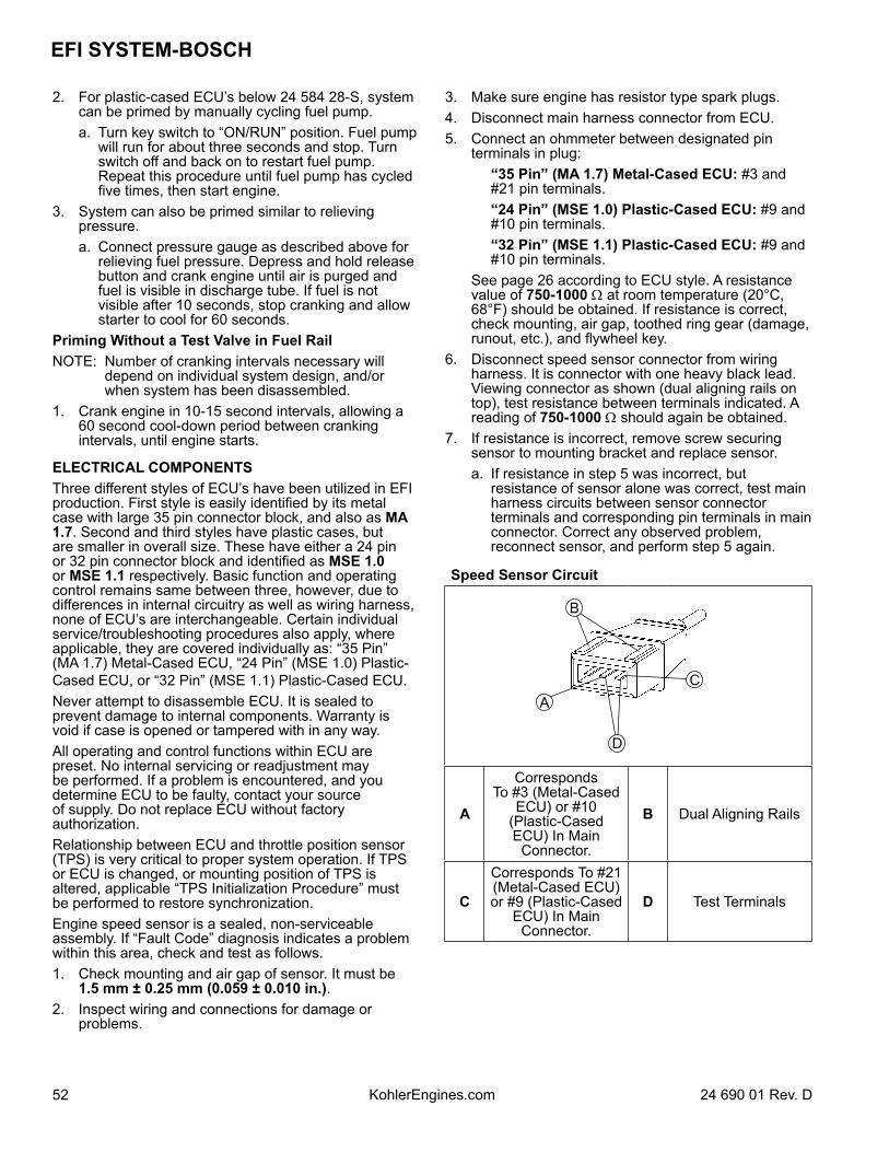
EFI SYSTEM-BOSCH
52 24 690 01 Rev. DKohlerEngines.com
2. For plastic-cased ECU’s below 24 584 28-S, system can be primed by manually cycling fuel pump.
a. Turn key switch to “ON/RUN” position. Fuel pump will run for about three seconds and stop. Turn switch off and back on to restart fuel pump. Repeat this procedure until fuel pump has cycled five times, then start engine.
3. System can also be primed similar to relieving pressure.
a. Connect pressure gauge as described above for relieving fuel pressure. Depress and hold release button and crank engine until air is purged and fuel is visible in discharge tube. If fuel is not visible after 10 seconds, stop cranking and allow starter to cool for 60 seconds.
Priming Without a Test Valve in Fuel RailNOTE: Number of cranking intervals necessary will
depend on individual system design, and/or when system has been disassembled.
1. Crank engine in 10-15 second intervals, allowing a 60 second cool-down period between cranking intervals, until engine starts.
ELECTRICAL COMPONENTSThree different styles of ECU’s have been utilized in EFI production. First style is easily identified by its metal case with large 35 pin connector block, and also as MA 1.7. Second and third styles have plastic cases, but are smaller in overall size. These have either a 24 pin or 32 pin connector block and identified as MSE 1.0 or MSE 1.1 respectively. Basic function and operating control remains same between three, however, due to differences in internal circuitry as well as wiring harness, none of ECU’s are interchangeable. Certain individual service/troubleshooting procedures also apply, where applicable, they are covered individually as: “35 Pin” (MA 1.7) Metal-Cased ECU, “24 Pin” (MSE 1.0) Plastic-Cased ECU, or “32 Pin” (MSE 1.1) Plastic-Cased ECU.Never attempt to disassemble ECU. It is sealed to prevent damage to internal components. Warranty is void if case is opened or tampered with in any way.All operating and control functions within ECU are preset. No internal servicing or readjustment may be performed. If a problem is encountered, and you determine ECU to be faulty, contact your source of supply. Do not replace ECU without factory authorization.Relationship between ECU and throttle position sensor (TPS) is very critical to proper system operation. If TPS or ECU is changed, or mounting position of TPS is altered, applicable “TPS Initialization Procedure” must be performed to restore synchronization.Engine speed sensor is a sealed, non-serviceable assembly. If “Fault Code” diagnosis indicates a problem within this area, check and test as follows.1. Check mounting and air gap of sensor. It must be
1.5 mm ± 0.25 mm (0.059 ± 0.010 in.).2. Inspect wiring and connections for damage or
problems.
3. Make sure engine has resistor type spark plugs.4. Disconnect main harness connector from ECU. 5. Connect an ohmmeter between designated pin
terminals in plug: “35 Pin” (MA 1.7) Metal-Cased ECU: #3 and
#21 pin terminals. “24 Pin” (MSE 1.0) Plastic-Cased ECU: #9 and
#10 pin terminals. “32 Pin” (MSE 1.1) Plastic-Cased ECU: #9 and
#10 pin terminals. See page 26 according to ECU style. A resistance
value of 750-1000 Ω at room temperature (20°C, 68°F) should be obtained. If resistance is correct, check mounting, air gap, toothed ring gear (damage, runout, etc.), and flywheel key.
6. Disconnect speed sensor connector from wiring harness. It is connector with one heavy black lead. Viewing connector as shown (dual aligning rails on top), test resistance between terminals indicated. A reading of 750-1000 Ω should again be obtained.
7. If resistance is incorrect, remove screw securing sensor to mounting bracket and replace sensor.
a. If resistance in step 5 was incorrect, but resistance of sensor alone was correct, test main harness circuits between sensor connector terminals and corresponding pin terminals in main connector. Correct any observed problem, reconnect sensor, and perform step 5 again.
Speed Sensor Circuit
A
D
C
B
A
Corresponds To #3 (Metal-Cased
ECU) or #10 (Plastic-Cased ECU) In Main
Connector.
B Dual Aligning Rails
C
Corresponds To #21 (Metal-Cased ECU) or #9 (Plastic-Cased
ECU) In Main Connector.
D Test Terminals
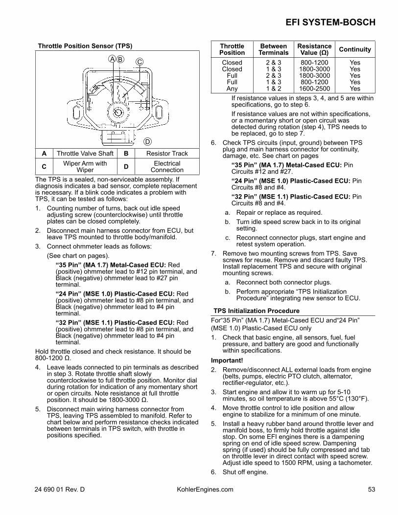
5324 690 01 Rev. D KohlerEngines.com
EFI SYSTEM-BOSCH
Throttle Position Sensor (TPS)
A CB
D
A Throttle Valve Shaft B Resistor Track
C Wiper Arm with Wiper D Electrical
ConnectionThe TPS is a sealed, non-serviceable assembly. If diagnosis indicates a bad sensor, complete replacement is necessary. If a blink code indicates a problem with TPS, it can be tested as follows:1. Counting number of turns, back out idle speed
adjusting screw (counterclockwise) until throttle plates can be closed completely.
2. Disconnect main harness connector from ECU, but leave TPS mounted to throttle body/manifold.
3. Connect ohmmeter leads as follows: (See chart on pages). “35 Pin” (MA 1.7) Metal-Cased ECU: Red
(positive) ohmmeter lead to #12 pin terminal, and Black (negative) ohmmeter lead to #27 pin terminal.
“24 Pin” (MSE 1.0) Plastic-Cased ECU: Red (positive) ohmmeter lead to #8 pin terminal, and Black (negative) ohmmeter lead to #4 pin terminal.
“32 Pin” (MSE 1.1) Plastic-Cased ECU: Red (positive) ohmmeter lead to #8 pin terminal, and Black (negative) ohmmeter lead to #4 pin terminal.
Hold throttle closed and check resistance. It should be 800-1200 Ω.4. Leave leads connected to pin terminals as described
in step 3. Rotate throttle shaft slowly counterclockwise to full throttle position. Monitor dial during rotation for indication of any momentary short or open circuits. Note resistance at full throttle position. It should be 1800-3000 Ω.
5. Disconnect main wiring harness connector from TPS, leaving TPS assembled to manifold. Refer to chart below and perform resistance checks indicated between terminals in TPS switch, with throttle in positions specified.
Throttle Position
Between Terminals
Resistance Value (Ω) Continuity
ClosedClosed
FullFullAny
2 & 31 & 32 & 31 & 31 & 2
800-12001800-30001800-3000800-12001600-2500
YesYesYesYesYes
If resistance values in steps 3, 4, and 5 are within specifications, go to step 6.
If resistance values are not within specifications, or a momentary short or open circuit was detected during rotation (step 4), TPS needs to be replaced, go to step 7.
6. Check TPS circuits (input, ground) between TPS plug and main harness connector for continuity, damage, etc. See chart on pages
“35 Pin” (MA 1.7) Metal-Cased ECU: Pin Circuits #12 and #27.
“24 Pin” (MSE 1.0) Plastic-Cased ECU: Pin Circuits #8 and #4.
“32 Pin” (MSE 1.1) Plastic-Cased ECU: Pin Circuits #8 and #4.
a. Repair or replace as required. b. Turn idle speed screw back in to its original
setting. c. Reconnect connector plugs, start engine and
retest system operation.7. Remove two mounting screws from TPS. Save
screws for reuse. Remove and discard faulty TPS. Install replacement TPS and secure with original mounting screws.
a. Reconnect both connector plugs. b. Perform appropriate “TPS Initialization
Procedure” integrating new sensor to ECU.
TPS Initialization ProcedureFor“35 Pin” (MA 1.7) Metal-Cased ECU and“24 Pin” (MSE 1.0) Plastic-Cased ECU only1. Check that basic engine, all sensors, fuel, fuel
pressure, and battery are good and functionally within specifications.
Important!2. Remove/disconnect ALL external loads from engine
(belts, pumps, electric PTO clutch, alternator, rectifier-regulator, etc.).
3. Start engine and allow it to warm up for 5-10 minutes, so oil temperature is above 55°C (130°F).
4. Move throttle control to idle position and allow engine to stabilize for a minimum of one minute.
5. Install a heavy rubber band around throttle lever and manifold boss, to firmly hold throttle against idle stop. On some EFI engines there is a dampening spring on end of idle speed screw. Dampening spring (if used) should be fully compressed and tab on throttle lever in direct contact with speed screw. Adjust idle speed to 1500 RPM, using a tachometer.
6. Shut off engine.
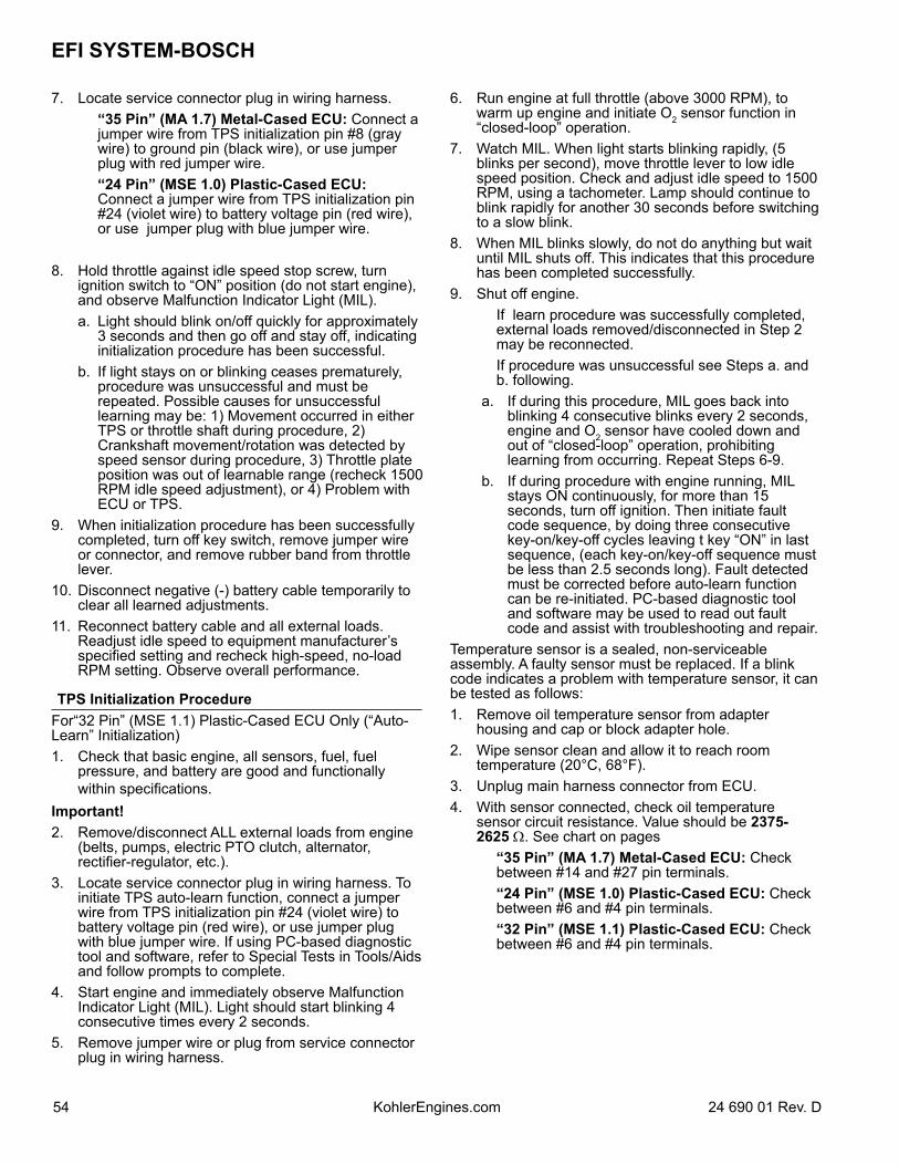
EFI SYSTEM-BOSCH
54 24 690 01 Rev. DKohlerEngines.com
7. Locate service connector plug in wiring harness. “35 Pin” (MA 1.7) Metal-Cased ECU: Connect a
jumper wire from TPS initialization pin #8 (gray wire) to ground pin (black wire), or use jumper plug with red jumper wire.
“24 Pin” (MSE 1.0) Plastic-Cased ECU: Connect a jumper wire from TPS initialization pin #24 (violet wire) to battery voltage pin (red wire), or use jumper plug with blue jumper wire.
8. Hold throttle against idle speed stop screw, turn ignition switch to “ON” position (do not start engine), and observe Malfunction Indicator Light (MIL).
a. Light should blink on/off quickly for approximately 3 seconds and then go off and stay off, indicating initialization procedure has been successful.
b. If light stays on or blinking ceases prematurely, procedure was unsuccessful and must be repeated. Possible causes for unsuccessful learning may be: 1) Movement occurred in either TPS or throttle shaft during procedure, 2) Crankshaft movement/rotation was detected by speed sensor during procedure, 3) Throttle plate position was out of learnable range (recheck 1500 RPM idle speed adjustment), or 4) Problem with ECU or TPS.
9. When initialization procedure has been successfully completed, turn off key switch, remove jumper wire or connector, and remove rubber band from throttle lever.
10. Disconnect negative (-) battery cable temporarily to clear all learned adjustments.
11. Reconnect battery cable and all external loads. Readjust idle speed to equipment manufacturer’s specified setting and recheck high-speed, no-load RPM setting. Observe overall performance.
TPS Initialization ProcedureFor“32 Pin” (MSE 1.1) Plastic-Cased ECU Only (“Auto-Learn” Initialization)1. Check that basic engine, all sensors, fuel, fuel
pressure, and battery are good and functionally within specifications.
Important!2. Remove/disconnect ALL external loads from engine
(belts, pumps, electric PTO clutch, alternator, rectifier-regulator, etc.).
3. Locate service connector plug in wiring harness. To initiate TPS auto-learn function, connect a jumper wire from TPS initialization pin #24 (violet wire) to battery voltage pin (red wire), or use jumper plug with blue jumper wire. If using PC-based diagnostic tool and software, refer to Special Tests in Tools/Aids and follow prompts to complete.
4. Start engine and immediately observe Malfunction Indicator Light (MIL). Light should start blinking 4 consecutive times every 2 seconds.
5. Remove jumper wire or plug from service connector plug in wiring harness.
6. Run engine at full throttle (above 3000 RPM), to warm up engine and initiate O2 sensor function in “closed-loop” operation.
7. Watch MIL. When light starts blinking rapidly, (5 blinks per second), move throttle lever to low idle speed position. Check and adjust idle speed to 1500 RPM, using a tachometer. Lamp should continue to blink rapidly for another 30 seconds before switching to a slow blink.
8. When MIL blinks slowly, do not do anything but wait until MIL shuts off. This indicates that this procedure has been completed successfully.
9. Shut off engine. If learn procedure was successfully completed,
external loads removed/disconnected in Step 2 may be reconnected.
If procedure was unsuccessful see Steps a. and b. following.
a. If during this procedure, MIL goes back into blinking 4 consecutive blinks every 2 seconds, engine and O2 sensor have cooled down and out of “closed-loop” operation, prohibiting learning from occurring. Repeat Steps 6-9.
b. If during procedure with engine running, MIL stays ON continuously, for more than 15 seconds, turn off ignition. Then initiate fault code sequence, by doing three consecutive key-on/key-off cycles leaving t key “ON” in last sequence, (each key-on/key-off sequence must be less than 2.5 seconds long). Fault detected must be corrected before auto-learn function can be re-initiated. PC-based diagnostic tool and software may be used to read out fault code and assist with troubleshooting and repair.
Temperature sensor is a sealed, non-serviceable assembly. A faulty sensor must be replaced. If a blink code indicates a problem with temperature sensor, it can be tested as follows:1. Remove oil temperature sensor from adapter
housing and cap or block adapter hole.2. Wipe sensor clean and allow it to reach room
temperature (20°C, 68°F).3. Unplug main harness connector from ECU.4. With sensor connected, check oil temperature
sensor circuit resistance. Value should be 2375-2625 Ω. See chart on pages
“35 Pin” (MA 1.7) Metal-Cased ECU: Check between #14 and #27 pin terminals.
“24 Pin” (MSE 1.0) Plastic-Cased ECU: Check between #6 and #4 pin terminals.
“32 Pin” (MSE 1.1) Plastic-Cased ECU: Check between #6 and #4 pin terminals.
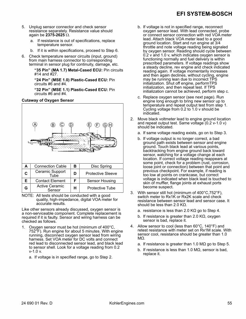
5524 690 01 Rev. D KohlerEngines.com
EFI SYSTEM-BOSCH
5. Unplug sensor connector and check sensor resistance separately. Resistance value should again be 2375-2625 Ω.
a. If resistance is out of specifications, replace temperature sensor.
b. If it is within specifications, proceed to Step 6.6. Check temperature sensor circuits (input, ground)
from main harness connector to corresponding terminal in sensor plug for continuity, damage, etc.
“35 Pin” (MA 1.7) Metal-Cased ECU: Pin circuits #14 and #27.
“24 Pin” (MSE 1.0) Plastic-Cased ECU: Pin circuits #6 and #4.
“32 Pin” (MSE 1.1) Plastic-Cased ECU: Pin circuits #6 and #4.
Cutaway of Oxygen Sensor
A B C D E F G H
A Connection Cable B Disc Spring
C Ceramic Support Tube D Protective Sleeve
E Contact Element F Sensor Housing
G Active Ceramic Sensor H Protective Tube
NOTE: All tests should be conducted with a good quality, high-impedance, digital VOA meter for accurate results.
Like other sensors already discussed, oxygen sensor is a non-serviceable component. Complete replacement is required if it is faulty. Sensor and wiring harness can be checked as follows.1. Oxygen sensor must be hot (minimum of 400°C,
752°F). Run engine for about 5 minutes. With engine running, disconnect oxygen sensor lead from wiring harness. Set VOA meter for DC volts and connect red lead to disconnected sensor lead, and black lead to sensor shell. Look for a voltage reading from 0.2 v-1.0 v.
a. If voltage is in specified range, go to Step 2.
b. If voltage is not in specified range, reconnect oxygen sensor lead. With lead connected, probe or connect sensor connection with red VOA meter lead. Attach black VOA meter lead to a good ground location. Start and run engine at 3/4 throttle and note voltage reading being signaled by oxygen sensor. Reading should cycle between 0.2 v and 1.0 v, which indicates oxygen sensor is functioning normally and fuel delivery is within prescribed parameters. If voltage readings show a steady decline, rev engine and check indicated reading again. If voltage momentarily increases and then again declines, without cycling, engine may be running lean due to incorrect TPS initialization. Shut off engine, performTPS initialization, and then repeat test. If TPS initialization cannot be achieved, perform step c.
c. Replace oxygen sensor (see next page). Run engine long enough to bring new sensor up to temperature and repeat output test from step 1. Cycling voltage from 0.2 to 1.0 v should be indicated.
2. Move black voltmeter lead to engine ground location and repeat output test. Same voltage (0.2 v-1.0 v) should be indicated.
a. If same voltage reading exists, go on to Step 3. b. If voltage output is no longer correct, a bad
ground path exists between sensor and engine ground. Touch black lead at various points, backtracking from engine ground back toward sensor, watching for a voltage change at each location. If correct voltage reading reappears at some point, check for a problem (rust, corrosion, loose joint or connection) between that point and previous checkpoint. For example, if reading is too low at points on crankcase, but correct voltage is indicated when black lead is touched to skin of muffler, flange joints at exhaust ports become suspect.
3. With sensor still hot (minimum of 400°C,752°F), switch meter to Rx1K or Rx2K scale and check resistance between sensor lead and sensor case. It should be less than 2.0 KΩ.
a. resistance is less than 2.0 KΩ go to Step 4. b. If resistance is greater than 2.0 KΩ, oxygen
sensor is bad, replace it.4. Allow sensor to cool (less than 60°C, 140°F) and
retest resistance with meter set on Rx1M scale. With sensor cool, resistance should be greater than 1.0 MΩ.
a. If resistance is greater than 1.0 MΩ go to Step 5. b. If resistance is less than 1.0 MΩ, sensor is bad,
replace it.
EFI SYSTEM-BOSCH
56 24 690 01 Rev. DKohlerEngines.com
5. With oxygen sensor disconnected and engine not running, disconnect main harness connector from ECU and set meter to Rx1 scale. Check circuit continuity as follows.
“24 Pin” (MSE 1.0) Plastic-Cased ECU: Check for continuity from pin #15 of ECU connector (see page ) to shell of oxygen sensor, and from pin #11 to sensor connector terminal of main harness. Both tests should indicate continuity.
“32 Pin” (MSE 1.1) Plastic-Cased ECU: Check for continuity from pin #19 of ECU connector (see page) to shell of oxygen sensor, and from pin #20 to sensor terminal of main harness. Both tests should indicate continuity.
a. If there is no continuity displayed in either of tests, check harness circuit for breaks or damage, and connections for poor contact, moisture, or corrosion. If no continuity was found in first test, also check for a poor/broken ground path back through exhaust system, engine, and mounting (sensor is grounded through its shell).
b. If continuity is indicated, go to step 6.6. With key switch in ON/RUN position, using a high
impedance voltmeter, check voltage from wiring harness oxygen sensor connector to engine ground location. Look for a steady voltage from 350-550 mv (0.35-0.55 v).
a. If voltage reading is not as specified, move black voltmeter lead to negative post of battery, to be certain of a good ground. If voltage is still not correct, ECU is probably bad.
b. If voltage readings are correct, clear fault codes and run engine to check if any fault codes reappear.
To Replace Oxygen Sensor1. Disconnect oxygen sensor connector from wiring
harness.2. Loosen and remove oxygen sensor from exhaust
manifold/muffler assembly.3. Apply anti-seize compound sparingly to threads of
new oxygen sensor, if none already exists. DO NOT get any on tip as it will contaminate sensor. Install sensor and torque to 50-60 N·m (37-44 ft. lb.).
4. Reconnect lead to wiring harness connector. Make sure it can not contact hot surfaces, moving parts, etc.
5. Test run engine.A malfunctioning relay can result in starting or operating difficulties. Relay and related wiring can be tested as follows:1. Disconnect relay connector plug from relay.2. Connect black lead of VOA meter to a chassis
ground location. Connect red lead to #86 terminal in relay connector. Set meter to test resistance (Rx1). Turn ignition switch from OFF to ON. Meter should indicate continuity (ground circuit is completed) for 1 to 3 seconds. Turn key switch back off.
a. Clean connection and check wiring if circuit was not completed.
3. Set meter for DC voltage. Touch red tester lead to #30 terminal in relay connector. A reading of 12 volts should be indicated at all times.
4. Connect red lead of meter to #85 terminal in relay connector. Turn key switch to ON position. Battery voltage should be present.
a. No voltage present indicates a problem with key switch, in wiring, or at connector.
b. If voltage is present, wiring to connector is good. Turn ignition switch ‘OFF and proceed to Step 5 to test relay.
5. Connect an ohmmeter (Rx1 scale) between #85 and #86 terminals in relay. There should be continuity.
6. Attach ohmmeter leads to #30 and #87 terminals in relay. First, there should be no continuity. Using a 12 volt power supply, connect positive (+) lead to #85 terminal and touch negative (-) lead to #86 terminal. When 12 volts is applied, relay should activate and continuity should exist between #30 and #87 terminals. Repeat test several times. If, at any time t relay fails to activate tcircuit, replace relay.
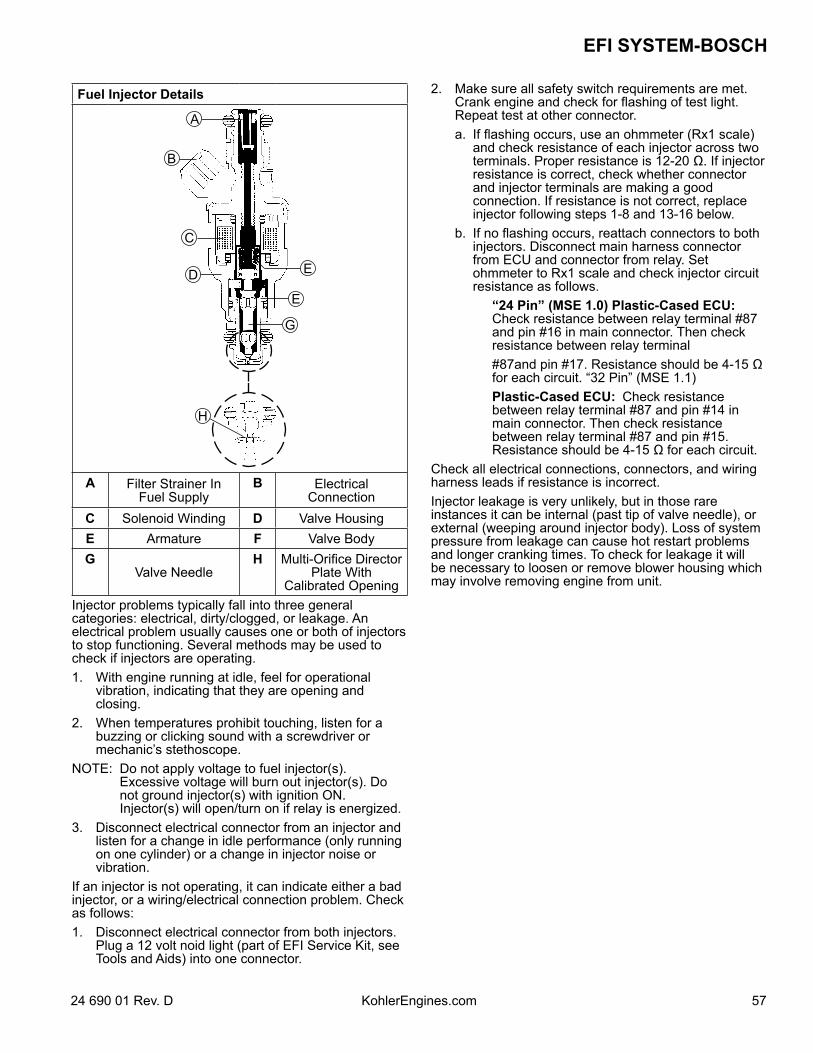
5724 690 01 Rev. D KohlerEngines.com
EFI SYSTEM-BOSCH
Fuel Injector Details
A
C
D E
B
E
G
H
A Filter Strainer In Fuel Supply
B Electrical Connection
C Solenoid Winding D Valve HousingE Armature F Valve BodyG
Valve NeedleH Multi-Orifice Director
Plate With Calibrated Opening
Injector problems typically fall into three general categories: electrical, dirty/clogged, or leakage. An electrical problem usually causes one or both of injectors to stop functioning. Several methods may be used to check if injectors are operating. 1. With engine running at idle, feel for operational
vibration, indicating that they are opening and closing.
2. When temperatures prohibit touching, listen for a buzzing or clicking sound with a screwdriver or mechanic’s stethoscope.
NOTE: Do not apply voltage to fuel injector(s). Excessive voltage will burn out injector(s). Do not ground injector(s) with ignition ON. Injector(s) will open/turn on if relay is energized.
3. Disconnect electrical connector from an injector and listen for a change in idle performance (only running on one cylinder) or a change in injector noise or vibration.
If an injector is not operating, it can indicate either a bad injector, or a wiring/electrical connection problem. Check as follows:1. Disconnect electrical connector from both injectors.
Plug a 12 volt noid light (part of EFI Service Kit, see Tools and Aids) into one connector.
2. Make sure all safety switch requirements are met. Crank engine and check for flashing of test light. Repeat test at other connector.
a. If flashing occurs, use an ohmmeter (Rx1 scale) and check resistance of each injector across two terminals. Proper resistance is 12-20 Ω. If injector resistance is correct, check whether connector and injector terminals are making a good connection. If resistance is not correct, replace injector following steps 1-8 and 13-16 below.
b. If no flashing occurs, reattach connectors to both injectors. Disconnect main harness connector from ECU and connector from relay. Set ohmmeter to Rx1 scale and check injector circuit resistance as follows.
“24 Pin” (MSE 1.0) Plastic-Cased ECU: Check resistance between relay terminal #87 and pin #16 in main connector. Then check resistance between relay terminal
#87and pin #17. Resistance should be 4-15 Ω for each circuit. “32 Pin” (MSE 1.1)
Plastic-Cased ECU: Check resistance between relay terminal #87 and pin #14 in main connector. Then check resistance between relay terminal #87 and pin #15. Resistance should be 4-15 Ω for each circuit.
Check all electrical connections, connectors, and wiring harness leads if resistance is incorrect.Injector leakage is very unlikely, but in those rare instances it can be internal (past tip of valve needle), or external (weeping around injector body). Loss of system pressure from leakage can cause hot restart problems and longer cranking times. To check for leakage it will be necessary to loosen or remove blower housing which may involve removing engine from unit.
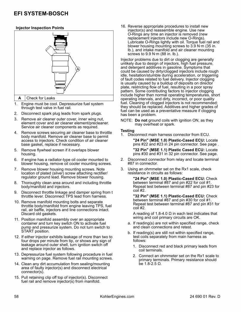
EFI SYSTEM-BOSCH
58 24 690 01 Rev. DKohlerEngines.com
Injector Inspection Points
A
A Check for Leaks1. Engine must be cool. Depressurize fuel system
through test valve in fuel rail.2. Disconnect spark plug leads from spark plugs.3. Remove air cleaner outer cover, inner wing nut,
element cover and air cleaner element/precleaner. Service air cleaner components as required.
4. Remove screws securing air cleaner base to throttle body manifold. Remove air cleaner base to permit access to injectors. Check condition of air cleaner base gasket, replace if necessary.
5. Remove flywheel screen if it overlaps blower housing.
6. If engine has a radiator-type oil cooler mounted to blower housing, remove oil cooler mounting screws.
7. Remove blower housing mounting screws. Note location of plated (silver) screw attaching rectifier/regulator ground lead. Remove blower housing.
8. Thoroughly clean area around and including throttle body/manifold and injectors.
9. Disconnect throttle linkage and damper spring from t throttle lever. Disconnect TPS lead from harness.
10. Remove manifold mounting bolts and separate throttle body/manifold from engine leaving TPS, fuel rail, air baffle, injectors and line connections intact. Discard old gaskets.
11. Position manifold assembly over an appropriate container and turn key switch ON to activate fuel pump and pressurize system. Do not turn switch to START position.
12. If either injector exhibits leakage of more than two to four drops per minute from tip, or shows any sign of leakage around outer shell, turn ignition switch off and replace injector as follows.
13. Depressurize fuel system following procedure in fuel warning on page. Remove fuel rail mounting screws.
14. Clean any dirt accumulation from sealing/mounting area of faulty injector(s) and disconnect electrical connector(s).
15. Pull retaining clip off top of injector(s). Disconnect fuel rail and remove injector(s) from manifold.
16. Reverse appropriate procedures to install new injector(s) and reassemble engine. Use new O-Rings any time an injector is removed (new replacement injectors include new O-Rings). Lubricate O-Rings lightly with oil. Torque fuel rail and blower housing mounting screws to 3.9 N·m (35 in. lb.), and intake manifold and air cleaner mounting screws to 9.9 N·m (88 in. lb.).
Injector problems due to dirt or clogging are generally unlikely due to design of injectors, high fuel pressure, and detergent additives in gasoline. Symptoms that could be caused by dirty/clogged injectors include rough idle, hesitation/stumble during acceleration, or triggering of fault codes related to fuel delivery. Injector clogging is usually caused by a buildup of deposits on director plate, restricting flow of fuel, resulting in a poor spray pattern. Some contributing factors to injector clogging include higher than normal operating temperatures, short operating intervals, and dirty, incorrect, or poor quality fuel. Cleaning of clogged injectors is not recommended; they should be replaced. Additives and higher grades of fuel can be used as a preventative measure if clogging has been a problem. NOTE: Do not ground coils with ignition ON, as they
may overheat or spark.Testing1. Disconnect main harness connector from ECU. "24 Pin" (MSE 1.0) Plastic-Cased ECU: Locate
pins #22 and #23 in 24 pin connector. See page . "32 Pin" (MSE 1.1) Plastic Cased ECU: Locate
pins #30 and #31 in 32 pin connector. See page.2. Disconnect connector from relay and locate terminal
#87 in connector.3. Using an ohmmeter set on the Rx1 scale, check
resistance in circuits as follows: "24 Pin" (MSE 1.0) Plastic-Cased ECU: Check
between terminal #87 and pin #22 for coil #1. Repeat test between terminal #87 and pin #23 for coil #2.
"32 Pin" (MSE 1.1) Plastic-Cased ECU: Check between terminal #87 and pin #30 for coil #1. Repeat test between terminal #87 and pin #31 for coil #2.
A reading of 1.8-4.0 Ω in each test indicates that wiring and coil primary circuits are OK.
a. If reading(s) are not within specified range, check and clean connections and retest.
b. If reading(s) are still not within specified range, test coils separately from main harness as follows:
1. Disconnect red and black primary leads from coil terminals.
2. Connect an ohmmeter set on the Rx1 scale to primary terminals. Primary resistance should be 1.8-2.5 Ω.
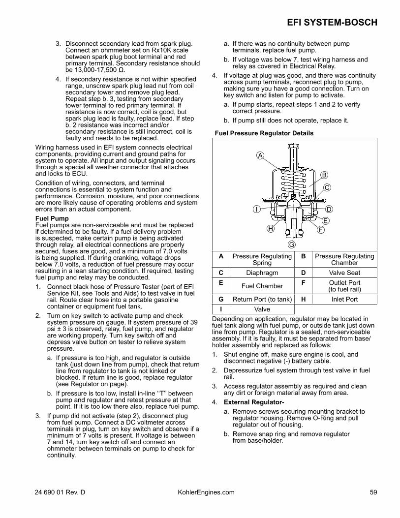
5924 690 01 Rev. D KohlerEngines.com
EFI SYSTEM-BOSCH
3. Disconnect secondary lead from spark plug. Connect an ohmmeter set on Rx10K scale between spark plug boot terminal and red primary terminal. Secondary resistance should be 13,000-17,500 Ω.
4. If secondary resistance is not within specified range, unscrew spark plug lead nut from coil secondary tower and remove plug lead. Repeat step b. 3, testing from secondary tower terminal to red primary terminal. If resistance is now correct, coil is good, but spark plug lead is faulty, replace lead. If step b. 2 resistance was incorrect and/or secondary resistance is still incorrect, coil is faulty and needs to be replaced.
Wiring harness used in EFI system connects electrical components, providing current and ground paths for system to operate. All input and output signaling occurs through a special all weather connector that attaches and locks to ECU.Condition of wiring, connectors, and terminal connections is essential to system function and performance. Corrosion, moisture, and poor connections are more likely cause of operating problems and system errors than an actual component. Fuel PumpFuel pumps are non-serviceable and must be replaced if determined to be faulty. If a fuel delivery problem is suspected, make certain pump is being activated through relay, all electrical connections are properly secured, fuses are good, and a minimum of 7.0 volts is being supplied. If during cranking, voltage drops below 7.0 volts, a reduction of fuel pressure may occur resulting in a lean starting condition. If required, testing fuel pump and relay may be conducted.1. Connect black hose of Pressure Tester (part of EFI
Service Kit, see Tools and Aids) to test valve in fuel rail. Route clear hose into a portable gasoline container or equipment fuel tank.
2. Turn on key switch to activate pump and check system pressure on gauge. If system pressure of 39 psi ± 3 is observed, relay, fuel pump, and regulator are working properly. Turn key switch off and depress valve button on tester to relieve system pressure.
a. If pressure is too high, and regulator is outside tank (just down line from pump), check that return line from regulator to tank is not kinked or blocked. If return line is good, replace regulator (see Regulator on page).
b. If pressure is too low, install in-line ‘‘T’’ between pump and regulator and retest pressure at that point. If it is too low there also, replace fuel pump.
3. If pump did not activate (step 2), disconnect plug from fuel pump. Connect a DC voltmeter across terminals in plug, turn on key switch and observe if a minimum of 7 volts is present. If voltage is between 7 and 14, turn key switch off and connect an ohmmeter between terminals on pump to check for continuity.
a. If there was no continuity between pump terminals, replace fuel pump.
b. If voltage was below 7, test wiring harness and relay as covered in Electrical Relay.
4. If voltage at plug was good, and there was continuity across pump terminals, reconnect plug to pump, making sure you have a good connection. Turn on key switch and listen for pump to activate.
a. If pump starts, repeat steps 1 and 2 to verify correct pressure.
b. If pump still does not operate, replace it.
Fuel Pressure Regulator Details
B
A
C
I D
EFH
G
A Pressure Regulating Spring
B Pressure Regulating Chamber
C Diaphragm D Valve SeatE Fuel Chamber F Outlet Port
(to fuel rail)G Return Port (to tank) H Inlet PortI Valve
Depending on application, regulator may be located in fuel tank along with fuel pump, or outside tank just down line from pump. Regulator is a sealed, non-serviceable assembly. If it is faulty, it must be separated from base/holder assembly and replaced as follows:1. Shut engine off, make sure engine is cool, and
disconnect negative (-) battery cable.2. Depressurize fuel system through test valve in fuel
rail.3. Access regulator assembly as required and clean
any dirt or foreign material away from area.4. External Regulator- a. Remove screws securing mounting bracket to
regulator housing. Remove O-Ring and pull regulator out of housing.
b. Remove snap ring and remove regulator from base/holder.
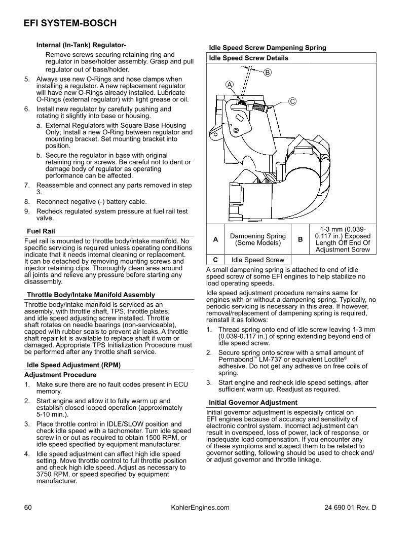
EFI SYSTEM-BOSCH
60 24 690 01 Rev. DKohlerEngines.com
Internal (In-Tank) Regulator- Remove screws securing retaining ring and
regulator in base/holder assembly. Grasp and pull regulator out of base/holder.
5. Always use new O-Rings and hose clamps when installing a regulator. A new replacement regulator will have new O-Rings already installed. Lubricate O-Rings (external regulator) with light grease or oil.
6. Install new regulator by carefully pushing and rotating it slightly into base or housing.
a. External Regulators with Square Base Housing Only; Install a new O-Ring between regulator and mounting bracket. Set mounting bracket into position.
b. Secure the regulator in base with original retaining ring or screws. Be careful not to dent or damage body of regulator as operating performance can be affected.
7. Reassemble and connect any parts removed in step 3.
8. Reconnect negative (-) battery cable.9. Recheck regulated system pressure at fuel rail test
valve.
Fuel RailFuel rail is mounted to throttle body/intake manifold. No specific servicing is required unless operating conditions indicate that it needs internal cleaning or replacement. It can be detached by removing mounting screws and injector retaining clips. Thoroughly clean area around all joints and relieve any pressure before starting any disassembly.
Throttle Body/Intake Manifold AssemblyThrottle body/intake manifold is serviced as an assembly, with throttle shaft, TPS, throttle plates, and idle speed adjusting screw installed. Throttle shaft rotates on needle bearings (non-serviceable), capped with rubber seals to prevent air leaks. A throttle shaft repair kit is available to replace shaft if worn or damaged. Appropriate TPS Initialization Procedure must be performed after any throttle shaft service.
Idle Speed Adjustment (RPM)Adjustment Procedure1. Make sure there are no fault codes present in ECU
memory.2. Start engine and allow it to fully warm up and
establish closed looped operation (approximately 5-10 min.).
3. Place throttle control in IDLE/SLOW position and check idle speed with a tachometer. Turn idle speed screw in or out as required to obtain 1500 RPM, or idle speed specified by equipment manufacturer.
4. Idle speed adjustment can affect high idle speed setting. Move throttle control to full throttle position and check high idle speed. Adjust as necessary to 3750 RPM, or speed specified by equipment manufacturer.
Idle Speed Screw Dampening SpringIdle Speed Screw Details
C
B
A
A Dampening Spring (Some Models) B
1-3 mm (0.039-0.117 in.) Exposed Length Off End Of Adjustment Screw
C Idle Speed ScrewA small dampening spring is attached to end of idle speed screw of some EFI engines to help stabilize no load operating speeds.Idle speed adjustment procedure remains same for engines with or without a dampening spring. Typically, no periodic servicing is necessary in this area. If however, removal/replacement of dampening spring is required, reinstall it as follows:1. Thread spring onto end of idle screw leaving 1-3 mm
(0.039-0.117 in.) of spring extending beyond end of idle speed screw.
2. Secure spring onto screw with a small amount of Permabond™ LM-737 or equivalent Loctite® adhesive. Do not get any adhesive on free coils of spring.
3. Start engine and recheck idle speed settings, after sufficient warm up. Readjust as required.
Initial Governor AdjustmentInitial governor adjustment is especially critical on EFI engines because of accuracy and sensitivity of electronic control system. Incorrect adjustment can result in overspeed, loss of power, lack of response, or inadequate load compensation. If you encounter any of these symptoms and suspect them to be related to governor setting, following should be used to check and/or adjust governor and throttle linkage.
6124 690 01 Rev. D KohlerEngines.com
EFI SYSTEM-BOSCH
If governor/throttle components are all intact, but you think there may be a problem with adjustment, follow Procedure A to check setting. If governor lever was loosened or removed, go immediately to Procedure B to perform initial adjustment.A. Checking Initial Adjustment 1. Unsnap plastic linkage bushing attaching throttle linkage to governor lever. Unhook damper spring from lever,
separate linkage from bushing, and remove bushing from lever. Mark hole position and unhook governor spring from governor lever.
2. Check if engine has a high-speed throttle stop screw installed in manifold casting boss. a. On engines without a stop screw, pivot throttle shaft and plate assembly into FULL THROTTLE position.
Insert a 1.52 mm (0.060 in.) feeler gauge between rear tang of throttle shaft plate and underside of manifold boss. Use a locking pliers (needle nose works best) to temporarily clamp parts in this position.
b. On engines with a stop screw, pivot throttle shaft and plate into FULL THROTTLE position, so tang of throttle shaft plate is against end of high-speed stop screw. Temporarily clamp in this position.
3. Rotate governor lever and shaft counterclockwise until it stops. Use only enough pressure to hold it in that position.
4. Check how end of throttle linkage aligns with bushing hole in governor lever. It should fall in center of hole. If it doesn’t, perform adjustment procedure as follows.
B. Setting Initial Adjustment 1. Check split where clamping screw goes through governor lever. There should be a gap of at least 1/32". If tips
are touching and there is no gap present, lever should be replaced. If not already installed, position governor lever on cross shaft, but leave clamping screw loose.
2. Follow instructions in Step 2 of Checking Initial Adjustment, then reattach throttle linkage to governor lever with bushing clip. It is not necessary to reattach damper or governor springs at this time.
3. Insert a nail into hole in top of cross shaft. Using light pressure, rotate governor shaft counterclockwise as far as it will turn, then torque nut on clamping screw to 6.8 N·m (60 in. lb.). Make sure that governor arm has not twisted up or down after nut has been tightened.
4. Verify that governor has been set correctly. With linkage still retained in FULL THROTTLE position (Step 2), unsnap bushing clip, separate linkage from bushing, and remove bushing from lever. Follow Steps 3 and 4 in Checking Initial Adjustment.
5. Reconnect dampening spring into its governor lever hole from bottom. Reinstall bushing and reattach throttle linkage. Reattach governor spring in marked hole.
6. Start engine and allow it to fully warm up and establish closed loop operation (approximately 5-10 min.). Check speed settings and adjust as necessary, first low idle speed, and then high speed setting.
TROUBLESHOOTINGTroubleshooting Guide
Condition Possible Cause
Engine Starts Hard or Fails to Start
When Cold.
Fuel pump not running.Faulty spark plugs.Old/stale fuel.Incorrect fuel pressure.Speed sensor loose or faulty.TPS offset incorrect (initialization).Engine temperature sensor faulty.Engine temp sensor faulty.Faulty coils.Low system voltage.Faulty injectors.
EFI SYSTEM-BOSCH
62 24 690 01 Rev. DKohlerEngines.com
Engine starts hard or fails to start
when hot
Faulty spark plugs.Fuel pump not running.Fuel pressure low.Insufficient fuel delivery.TPS offset incorrect (Initialization).Speed sensor loose or faulty.TPS faulty.Engine temperature sensor faulty.Faulty injectors.
Engine stalls or idles roughly (cold
or warm)
Faulty spark plugs.Insufficient fuel delivery.TPS offset incorrect.TPS faulty.Faulty engine temperature sensor.Faulty injectors.
Engine misses, hesitates, or stalls
under load
Fuel injector(s), fuel filter, fuel line, or fuel pick-up dirty/restricted.Dirty air cleaner.Insufficient fuel pressure or fuel delivery.Vacuum (intake air) leak.Improper governor setting, adjustment or operation.Speed sensor malfunction.TPS faulty, mounting problem or TPS Initialization Procedure incorrect.
Bad coil(s), spark plug(s), or wires.
Low Power
Faulty/malfunctioning ignition system.Dirty air filter.Insufficient fuel delivery.Improper governor adjustment.Plugged/restricted exhaust.One injector not working.Basic engine problem exists.TPS faulty or mounting exists.Throttle plates in throttle body/intake manifold not fully opening to WOT stop (if so equipped).
EFI system is a 12 VDC negative ground system, designed to operate down to a minimum of 7.0 volts. If system voltage drops below this level, operation of voltage sensitive components such as ECU, fuel pump, and injectors will be intermittent or disrupted, causing erratic operation or hard starting. A fully charged, 12 volt battery with a minimum of 350 cold cranking amps is important in maintaining steady and reliable system operation. Battery condition and state of charge should always be checked first when troubleshooting an operational problem.Keep in mind that EFI-related problems are more often caused by wiring harness or connections than by EFI components. Even small amounts of corrosion or oxidation on terminals can interfere with milliamp currents used in system operation. Cleaning connectors and grounds will solve problems in many cases.
In an emergency situation, simply disconnecting and reconnecting connectors may clean up contacts enough to restore operation, at least temporarily.If a fault code indicates a problem with an electrical component, disconnect ECU connector and test for continuity between component connector terminals and corresponding terminals in ECU connector using an ohmmeter. Little or no resistance should be measured, indicating that wiring of that particular circuit is OK. An illustrated listing of numerical terminal locations, for each style of ECU/connector is provided on pages 63, 65, and 67.
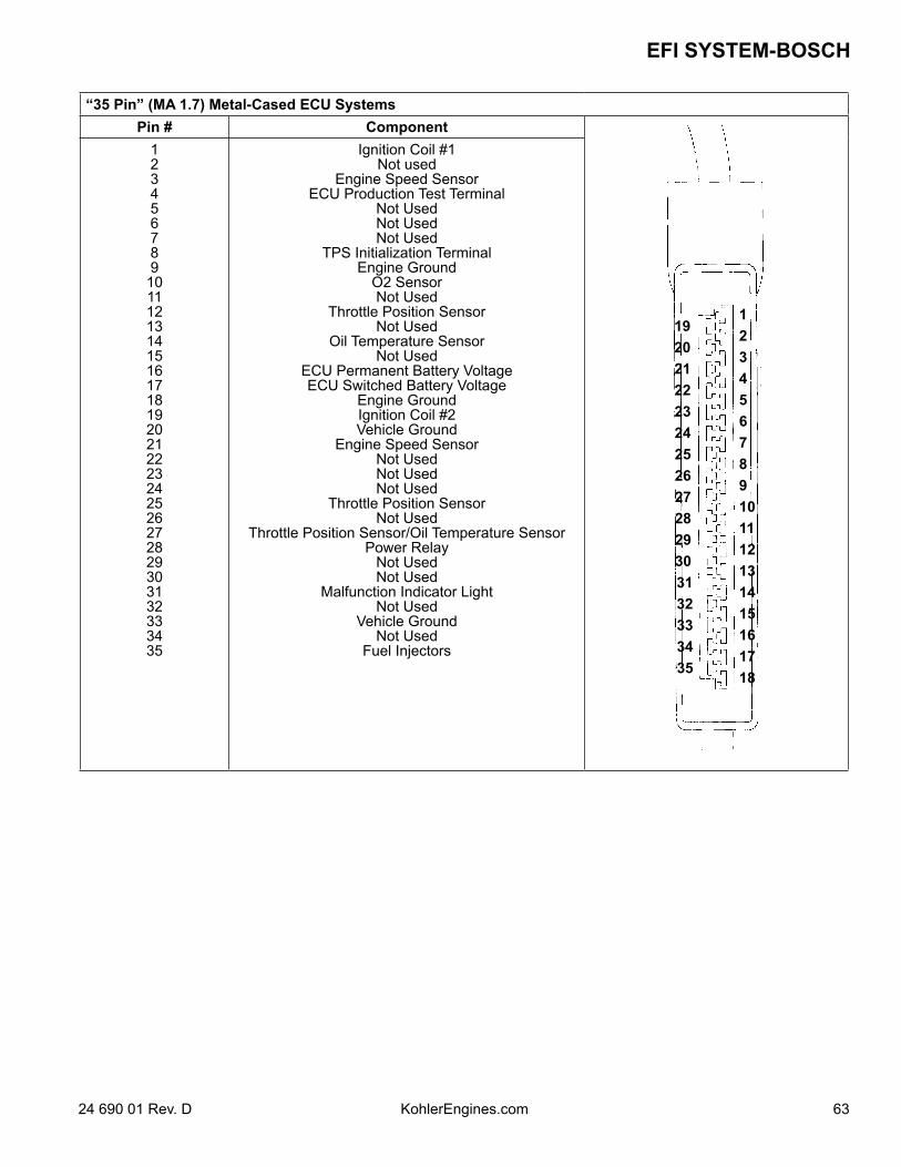
6324 690 01 Rev. D KohlerEngines.com
EFI SYSTEM-BOSCH
“35 Pin” (MA 1.7) Metal-Cased ECU SystemsPin # Component
123456789101112131415161718
1920212223242526272829303132333435
1234567891011121314151617181920212223242526272829303132333435
Ignition Coil #1Not used
Engine Speed SensorECU Production Test Terminal
Not UsedNot UsedNot Used
TPS Initialization TerminalEngine Ground
O2 SensorNot Used
Throttle Position SensorNot Used
Oil Temperature SensorNot Used
ECU Permanent Battery VoltageECU Switched Battery Voltage
Engine GroundIgnition Coil #2Vehicle Ground
Engine Speed SensorNot UsedNot UsedNot Used
Throttle Position SensorNot Used
Throttle Position Sensor/Oil Temperature SensorPower Relay
Not UsedNot Used
Malfunction Indicator LightNot Used
Vehicle GroundNot Used
Fuel Injectors
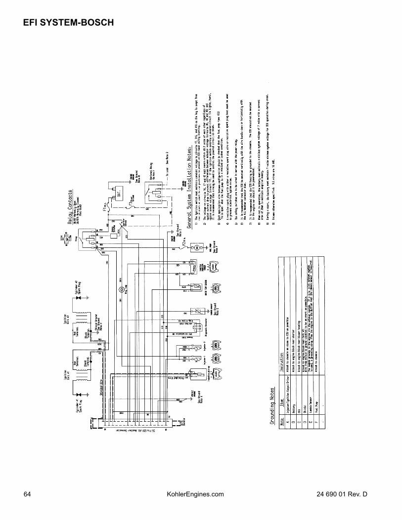
EFI SYSTEM-BOSCH
64 24 690 01 Rev. DKohlerEngines.com
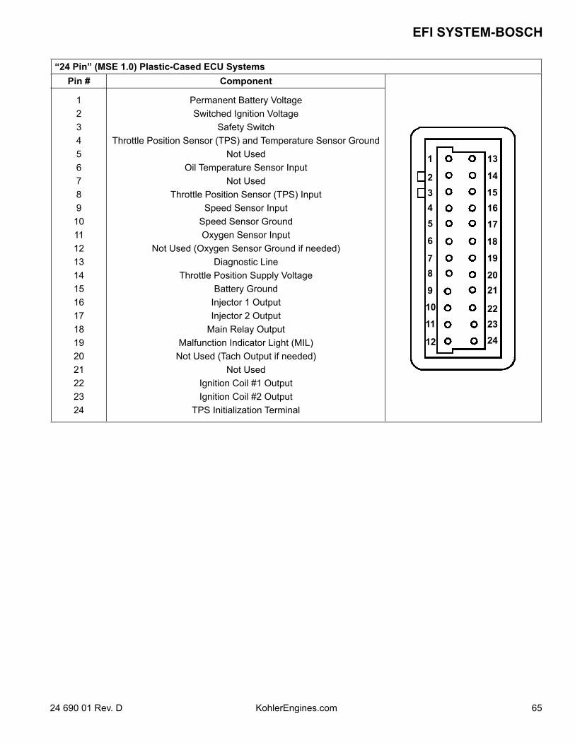
6524 690 01 Rev. D KohlerEngines.com
EFI SYSTEM-BOSCH
“24 Pin” (MSE 1.0) Plastic-Cased ECU SystemsPin # Component
1
2345
6
78
9
10
11
12
13
14
151617
18
19
2021
222324
123456789101112131415161718192021222324
Permanent Battery VoltageSwitched Ignition Voltage
Safety SwitchThrottle Position Sensor (TPS) and Temperature Sensor Ground
Not Used Oil Temperature Sensor Input
Not UsedThrottle Position Sensor (TPS) Input
Speed Sensor InputSpeed Sensor GroundOxygen Sensor Input
Not Used (Oxygen Sensor Ground if needed)Diagnostic Line
Throttle Position Supply VoltageBattery Ground
Injector 1 OutputInjector 2 Output
Main Relay Output Malfunction Indicator Light (MIL)
Not Used (Tach Output if needed)Not Used
Ignition Coil #1 OutputIgnition Coil #2 Output
TPS Initialization Terminal
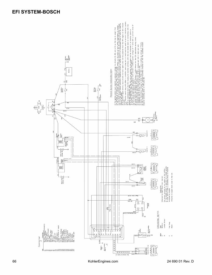
EFI SYSTEM-BOSCH
66 24 690 01 Rev. DKohlerEngines.com
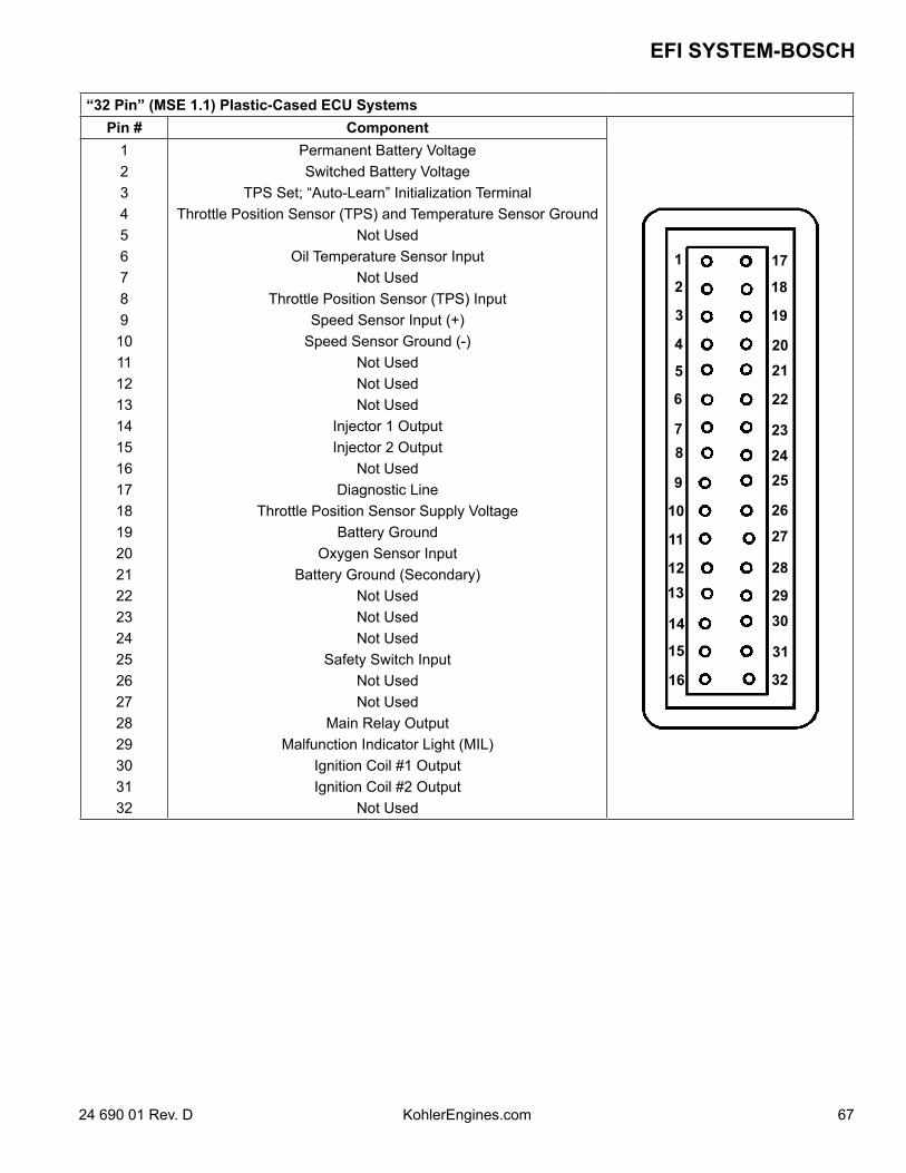
6724 690 01 Rev. D KohlerEngines.com
EFI SYSTEM-BOSCH
“32 Pin” (MSE 1.1) Plastic-Cased ECU SystemsPin # Component
1
2
3
4
5
6
78
9
10
11
12
17
18
19
2021
22
232425
26
27
2813
14
2930
15
16
31
32
1234567891011121314151617181920212223242526272829303132
Permanent Battery VoltageSwitched Battery Voltage
TPS Set; “Auto-Learn” Initialization TerminalThrottle Position Sensor (TPS) and Temperature Sensor Ground
Not UsedOil Temperature Sensor Input
Not UsedThrottle Position Sensor (TPS) Input
Speed Sensor Input (+)Speed Sensor Ground (-)
Not UsedNot UsedNot Used
Injector 1 OutputInjector 2 Output
Not UsedDiagnostic Line
Throttle Position Sensor Supply VoltageBattery Ground
Oxygen Sensor InputBattery Ground (Secondary)
Not UsedNot UsedNot Used
Safety Switch InputNot UsedNot Used
Main Relay OutputMalfunction Indicator Light (MIL)
Ignition Coil #1 OutputIgnition Coil #2 Output
Not Used
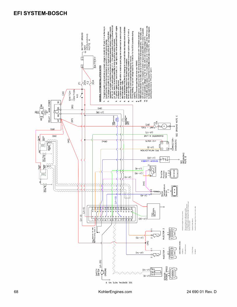
EFI SYSTEM-BOSCH
68 24 690 01 Rev. DKohlerEngines.com
6924 690 01 Rev. D KohlerEngines.com
EFI SYSTEM-BOSCH
Fuel System
WARNING: Fuel System Under Pressure!Fuel system operates under high pressure. System pressure must be relieved through test valve in fuel rail prior to servicing or removing any fuel system components. Do not smoke or work near heaters or other fire hazards. Have a fire extinguisher handy and work only in a well-ventilated area.Function of fuel system is to provide sufficient delivery of fuel at system operating pressure of 39 psi ± 3. If an engine starts hard, or turns over but will not start, it may indicate a problem with EFI fuel system. A quick test will verify if system is operating.1. Disconnect and ground spark plug leads.2. Complete all safety interlock requirements and crank
engine for approximately 3 seconds.3. Remove spark plugs and check for fuel at tips. a. If there is fuel at tips of spark plugs, fuel pump
and injectors are operating. b. If there is no fuel at tips of spark plugs, check
following.1. Make sure fuel tank contains clean, fresh, proper
fuel.2. Make sure that vent in fuel tank is open.3. Make sure fuel tank valve (if so equipped) is fully
opened.4. Make sure battery is supplying proper voltage.5. Check that fuses are good, and that all electrical and
fuel line connections are good.6. Test fuel pump and relay operation as described
earlier under Fuel Pump.
Fault CodesECU continuously monitors engine operation against preset performance limits. If operation is outside limits, ECU activates MIL and stores a diagnostic code in its fault memory. If component or system returns to proper function, ECU will eventually self-clear fault code and turn off MIL. If MIL stays illuminated, it warns customer that dealer service is required. Upon receipt, dealer technician can access fault code(s) to help determine what portion of system is malfunctioning. 2-digit blink codes available based upon style of ECU are listed on pages 70, 71, and 72.Codes are accessed through key switch and displayed as blinks or flashes of MIL. Access codes as follows.1. Start with key switch off.2. Turn key switch on-off-on-off-on, leaving it on in third
sequence. Time between sequences must be less than 2.5 seconds.
3. Any stored fault codes will then be displayed as a series of MIL blinks (from 2 to 6) representing first digit, followed by a pause, and another series of blinks (from 1 to 6) for second digit.
a. It’s a good idea to write down codes as they appear, as they may not be in numerical sequence.
b. Code 61 will always be last code displayed, indicating end of code transmission. If code 61 appears immediately, no other fault codes are present.
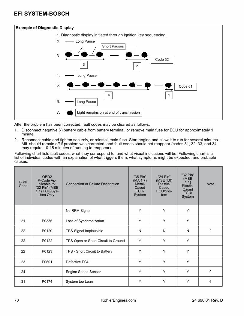
EFI SYSTEM-BOSCH
70 24 690 01 Rev. DKohlerEngines.com
Long PauseShort Pauses
Code 323 2
Code 61
16
Long Pause
Light remains on at end of transmission
1. Diagnostic display initiated through ignition key sequencing.
2.
Example of Diagnostic Display
Long Pause
3.
4.
5.
6.
7.
After the problem has been corrected, fault codes may be cleared as follows.1. Disconnect negative (-) battery cable from battery terminal, or remove main fuse for ECU for approximately 1
minute.2. Reconnect cable and tighten securely, or reinstall main fuse. Start engine and allow it to run for several minutes.
MIL should remain off if problem was corrected, and fault codes should not reappear (codes 31, 32, 33, and 34 may require 10-15 minutes of running to reappear).
Following chart lists fault codes, what they correspond to, and what visual indications will be. Following chart is a list of individual codes with an explanation of what triggers them, what symptoms might be expected, and probable causes.
BlinkCode
OBD2 P-Code Ap-plicable to:
"32 Pin" (MSE 1.1) ECU/Sys-
tem Only
Connection or Failure Description
"35 Pin" (MA 1.7) Metal-Cased ECU/
System
"24 Pin" (MSE 1.0)
Plastic-Cased
ECU/Sys-tem
"32 Pin" (MSE 1.1)
Plastic-Cased ECU/
System
Note
- - No RPM Signal Y Y Y
21 P0335 Loss of Synchronization Y Y Y
22 P0120 TPS-Signal Implausible N N N 2
22 P0122 TPS-Open or Short Circuit to Ground Y Y Y
22 P0123 TPS - Short Circuit to Battery Y Y Y
23 P0601 Defective ECU Y Y Y
24 Engine Speed Sensor Y Y Y 9
31 P0174 System too Lean Y Y Y 6
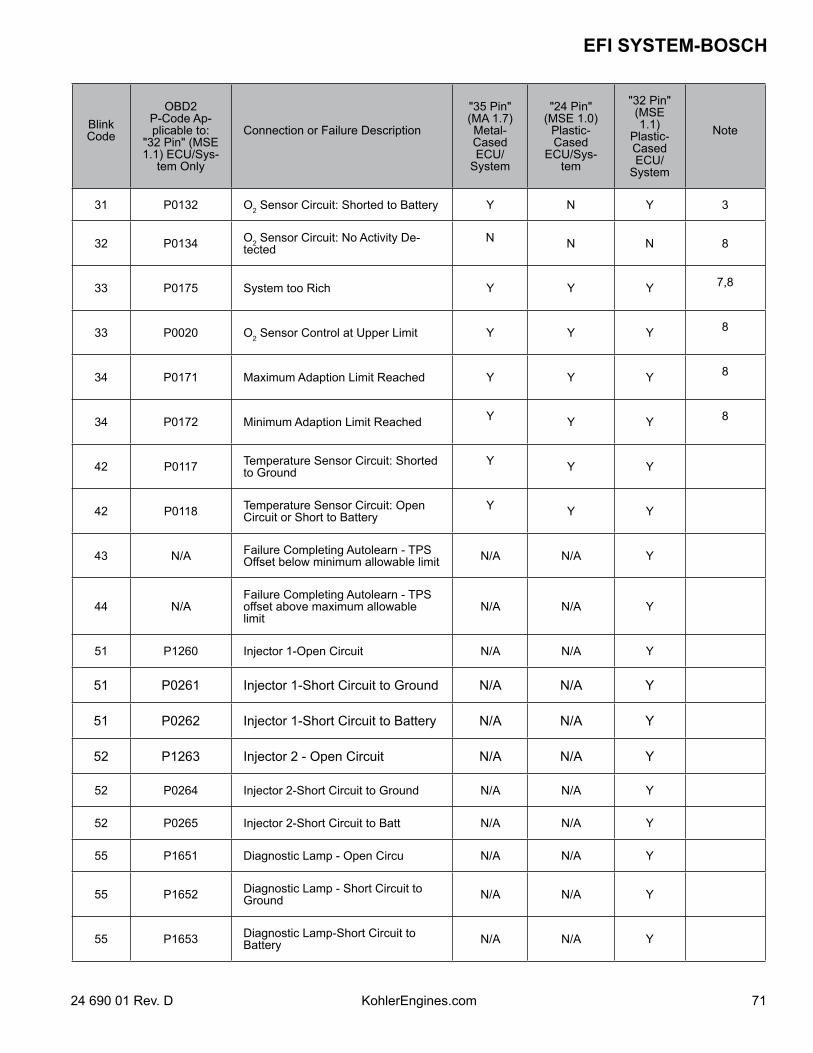
7124 690 01 Rev. D KohlerEngines.com
EFI SYSTEM-BOSCH
BlinkCode
OBD2 P-Code Ap-plicable to:
"32 Pin" (MSE 1.1) ECU/Sys-
tem Only
Connection or Failure Description
"35 Pin" (MA 1.7) Metal-Cased ECU/
System
"24 Pin" (MSE 1.0)
Plastic-Cased
ECU/Sys-tem
"32 Pin" (MSE 1.1)
Plastic-Cased ECU/
System
Note
31 P0132 O2 Sensor Circuit: Shorted to Battery Y N Y 3
32 P0134 O2 Sensor Circuit: No Activity De-tected
N N N 8
33 P0175 System too Rich Y Y Y 7,8
33 P0020 O2 Sensor Control at Upper Limit Y Y Y 8
34 P0171 Maximum Adaption Limit Reached Y Y Y 8
34 P0172 Minimum Adaption Limit Reached Y Y Y 8
42 P0117 Temperature Sensor Circuit: Shorted to Ground
Y Y Y
42 P0118 Temperature Sensor Circuit: Open Circuit or Short to Battery
Y Y Y
43 N/A Failure Completing Autolearn - TPS Offset below minimum allowable limit N/A N/A Y
44 N/AFailure Completing Autolearn - TPS offset above maximum allowable limit
N/A N/A Y
51 P1260 Injector 1-Open Circuit N/A N/A Y
51 P0261 Injector 1-Short Circuit to Ground N/A N/A Y
51 P0262 Injector 1-Short Circuit to Battery N/A N/A Y
52 P1263 Injector 2 - Open Circuit N/A N/A Y
52 P0264 Injector 2-Short Circuit to Ground N/A N/A Y
52 P0265 Injector 2-Short Circuit to Batt N/A N/A Y
55 P1651 Diagnostic Lamp - Open Circu N/A N/A Y
55 P1652 Diagnostic Lamp - Short Circuit to Ground N/A N/A Y
55 P1653 Diagnostic Lamp-Short Circuit to Battery N/A N/A Y
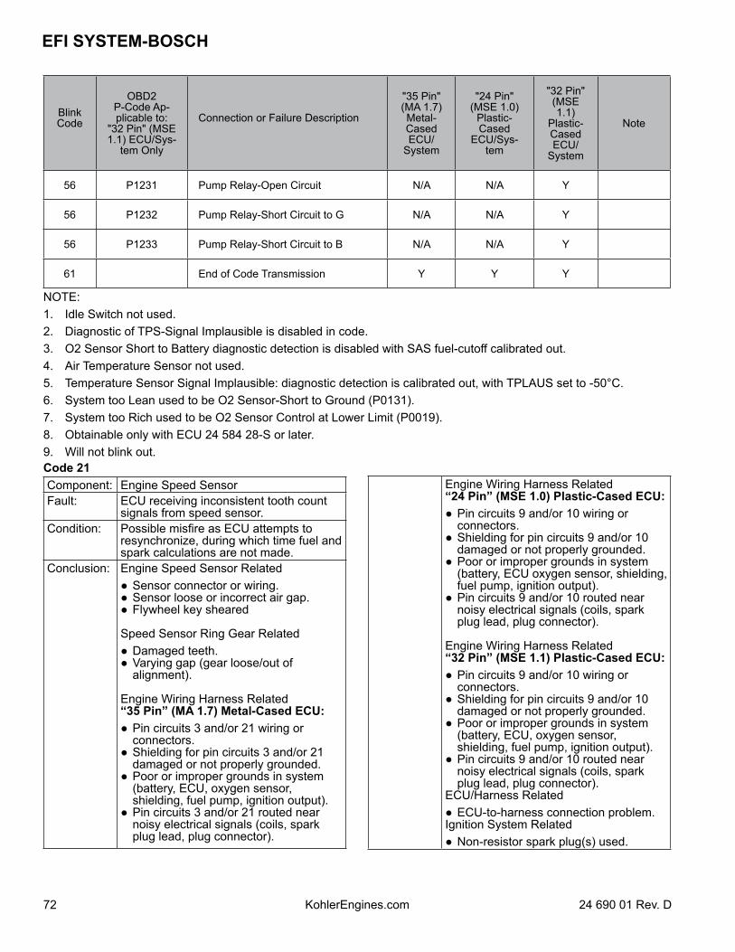
EFI SYSTEM-BOSCH
72 24 690 01 Rev. DKohlerEngines.com
BlinkCode
OBD2 P-Code Ap-plicable to:
"32 Pin" (MSE 1.1) ECU/Sys-
tem Only
Connection or Failure Description
"35 Pin" (MA 1.7) Metal-Cased ECU/
System
"24 Pin" (MSE 1.0)
Plastic-Cased
ECU/Sys-tem
"32 Pin" (MSE 1.1)
Plastic-Cased ECU/
System
Note
56 P1231 Pump Relay-Open Circuit N/A N/A Y
56 P1232 Pump Relay-Short Circuit to G N/A N/A Y
56 P1233 Pump Relay-Short Circuit to B N/A N/A Y
61 End of Code Transmission Y Y Y
NOTE:1. Idle Switch not used.2. Diagnostic of TPS-Signal Implausible is disabled in code.3. O2 Sensor Short to Battery diagnostic detection is disabled with SAS fuel-cutoff calibrated out.4. Air Temperature Sensor not used.5. Temperature Sensor Signal Implausible: diagnostic detection is calibrated out, with TPLAUS set to -50°C.6. System too Lean used to be O2 Sensor-Short to Ground (P0131).7. System too Rich used to be O2 Sensor Control at Lower Limit (P0019).8. Obtainable only with ECU 24 584 28-S or later.9. Will not blink out.Code 21Component: Engine Speed SensorFault: ECU receiving inconsistent tooth count
signals from speed sensor.Condition: Possible misfire as ECU attempts to
resynchronize, during which time fuel and spark calculations are not made.
Conclusion: Engine Speed Sensor Related Sensor connector or wiring. Sensor loose or incorrect air gap. Flywheel key sheared
Speed Sensor Ring Gear Related Damaged teeth. Varying gap (gear loose/out of
alignment).
Engine Wiring Harness Related “35 Pin” (MA 1.7) Metal-Cased ECU: Pin circuits 3 and/or 21 wiring or
connectors. Shielding for pin circuits 3 and/or 21
damaged or not properly grounded. Poor or improper grounds in system
(battery, ECU, oxygen sensor, shielding, fuel pump, ignition output).
Pin circuits 3 and/or 21 routed near noisy electrical signals (coils, spark plug lead, plug connector).
Engine Wiring Harness Related “24 Pin” (MSE 1.0) Plastic-Cased ECU: Pin circuits 9 and/or 10 wiring or
connectors. Shielding for pin circuits 9 and/or 10
damaged or not properly grounded. Poor or improper grounds in system
(battery, ECU oxygen sensor, shielding, fuel pump, ignition output).
Pin circuits 9 and/or 10 routed near noisy electrical signals (coils, spark plug lead, plug connector).
Engine Wiring Harness Related “32 Pin” (MSE 1.1) Plastic-Cased ECU: Pin circuits 9 and/or 10 wiring or
connectors. Shielding for pin circuits 9 and/or 10
damaged or not properly grounded. Poor or improper grounds in system
(battery, ECU, oxygen sensor, shielding, fuel pump, ignition output).
Pin circuits 9 and/or 10 routed near noisy electrical signals (coils, spark plug lead, plug connector).
ECU/Harness Related ECU-to-harness connection problem.Ignition System Related Non-resistor spark plug(s) used.
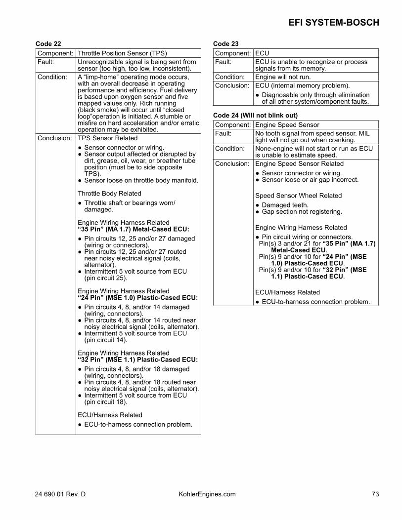
7324 690 01 Rev. D KohlerEngines.com
EFI SYSTEM-BOSCH
Code 22Component: Throttle Position Sensor (TPS)Fault: Unrecognizable signal is being sent from
sensor (too high, too low, inconsistent).Condition: A “limp-home” operating mode occurs,
with an overall decrease in operating performance and efficiency. Fuel delivery is based upon oxygen sensor and five mapped values only. Rich running (black smoke) will occur until “closed loop”operation is initiated. A stumble or misfire on hard acceleration and/or erratic operation may be exhibited.
Conclusion: TPS Sensor Related Sensor connector or wiring. Sensor output affected or disrupted by
dirt, grease, oil, wear, or breather tube position (must be to side opposite TPS).
Sensor loose on throttle body manifold.
Throttle Body Related Throttle shaft or bearings worn/
damaged.
Engine Wiring Harness Related “35 Pin” (MA 1.7) Metal-Cased ECU: Pin circuits 12, 25 and/or 27 damaged
(wiring or connectors). Pin circuits 12, 25 and/or 27 routed
near noisy electrical signal (coils, alternator).
Intermittent 5 volt source from ECU (pin circuit 25).
Engine Wiring Harness Related “24 Pin” (MSE 1.0) Plastic-Cased ECU: Pin circuits 4, 8, and/or 14 damaged
(wiring, connectors). Pin circuits 4, 8, and/or 14 routed near
noisy electrical signal (coils, alternator). Intermittent 5 volt source from ECU
(pin circuit 14).
Engine Wiring Harness Related “32 Pin” (MSE 1.1) Plastic-Cased ECU: Pin circuits 4, 8, and/or 18 damaged
(wiring, connectors). Pin circuits 4, 8, and/or 18 routed near
noisy electrical signal (coils, alternator). Intermittent 5 volt source from ECU
(pin circuit 18).
ECU/Harness Related ECU-to-harness connection problem.
Code 23Component: ECUFault: ECU is unable to recognize or process
signals from its memory.Condition: Engine will not run.Conclusion: ECU (internal memory problem).
Diagnosable only through elimination of all other system/component faults.
Code 24 (Will not blink out)Component: Engine Speed SensorFault: No tooth signal from speed sensor. MIL
light will not go out when cranking.Condition: None-engine will not start or run as ECU
is unable to estimate speed.Conclusion: Engine Speed Sensor Related
Sensor connector or wiring. Sensor loose or air gap incorrect.
Speed Sensor Wheel Related Damaged teeth. Gap section not registering.
Engine Wiring Harness Related Pin circuit wiring or connectors.Pin(s) 3 and/or 21 for “35 Pin” (MA 1.7)
Metal-Cased ECU.Pin(s) 9 and/or 10 for “24 Pin” (MSE
1.0) Plastic-Cased ECU.Pin(s) 9 and/or 10 for “32 Pin” (MSE
1.1) Plastic-Cased ECU.
ECU/Harness Related ECU-to-harness connection problem.
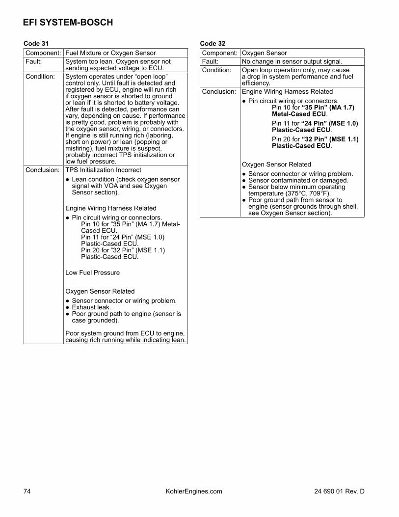
EFI SYSTEM-BOSCH
74 24 690 01 Rev. DKohlerEngines.com
Code 31Component: Fuel Mixture or Oxygen SensorFault: System too lean. Oxygen sensor not
sending expected voltage to ECU.Condition: System operates under “open loop”
control only. Until fault is detected and registered by ECU, engine will run rich if oxygen sensor is shorted to ground or lean if it is shorted to battery voltage. After fault is detected, performance can vary, depending on cause. If performance is pretty good, problem is probably with the oxygen sensor, wiring, or connectors. If engine is still running rich (laboring, short on power) or lean (popping or misfiring), fuel mixture is suspect, probably incorrect TPS initialization or low fuel pressure.
Conclusion: TPS Initialization Incorrect Lean condition (check oxygen sensor
signal with VOA and see Oxygen Sensor section).
Engine Wiring Harness Related Pin circuit wiring or connectors. Pin 10 for “35 Pin” (MA 1.7) Metal-
Cased ECU. Pin 11 for “24 Pin” (MSE 1.0)
Plastic-Cased ECU. Pin 20 for “32 Pin” (MSE 1.1)
Plastic-Cased ECU.
Low Fuel Pressure
Oxygen Sensor Related Sensor connector or wiring problem. Exhaust leak. Poor ground path to engine (sensor is
case grounded).
Poor system ground from ECU to engine, causing rich running while indicating lean.
Code 32Component: Oxygen SensorFault: No change in sensor output signal.Condition: Open loop operation only, may cause
a drop in system performance and fuel efficiency.
Conclusion: Engine Wiring Harness Related Pin circuit wiring or connectors. Pin 10 for “35 Pin” (MA 1.7)
Metal-Cased ECU. Pin 11 for “24 Pin” (MSE 1.0)
Plastic-Cased ECU. Pin 20 for “32 Pin” (MSE 1.1)
Plastic-Cased ECU.
Oxygen Sensor Related Sensor connector or wiring problem. Sensor contaminated or damaged. Sensor below minimum operating
temperature (375°C, 709°F). Poor ground path from sensor to
engine (sensor grounds through shell, see Oxygen Sensor section).
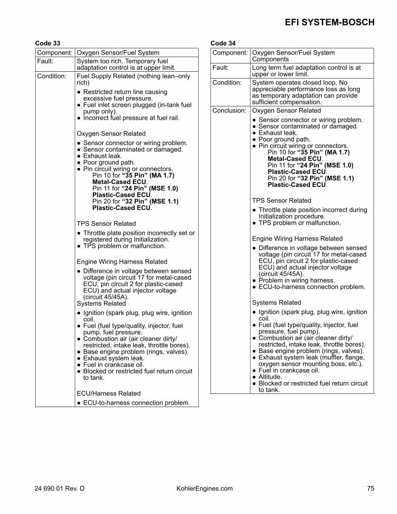
7524 690 01 Rev. D KohlerEngines.com
EFI SYSTEM-BOSCH
Code 33Component: Oxygen Sensor/Fuel SystemFault: System too rich. Temporary fuel
adaptation control is at upper limit.Condition: Fuel Supply Related (nothing lean–only
rich) Restricted return line causing
excessive fuel pressure. Fuel inlet screen plugged (in-tank fuel
pump only). Incorrect fuel pressure at fuel rail.
Oxygen Sensor Related Sensor connector or wiring problem. Sensor contaminated or damaged. Exhaust leak. Poor ground path. Pin circuit wiring or connectors. Pin 10 for “35 Pin” (MA 1.7)
Metal-Cased ECU. Pin 11 for “24 Pin” (MSE 1.0)
Plastic-Cased ECU. Pin 20 for “32 Pin” (MSE 1.1)
Plastic-Cased ECU.
TPS Sensor Related Throttle plate position incorrectly set or
registered during Initialization. TPS problem or malfunction.
Engine Wiring Harness Related Difference in voltage between sensed
voltage (pin circuit 17 for metal-cased ECU, pin circuit 2 for plastic-cased ECU) and actual injector voltage (circuit 45/45A).
Systems Related Ignition (spark plug, plug wire, ignition
coil. Fuel (fuel type/quality, injector, fuel
pump, fuel pressure. Combustion air (air cleaner dirty/
restricted, intake leak, throttle bores). Base engine problem (rings, valves). Exhaust system leak. Fuel in crankcase oil. Blocked or restricted fuel return circuit
to tank.
ECU/Harness Related ECU-to-harness connection problem.
Code 34Component: Oxygen Sensor/Fuel System
ComponentsFault: Long term fuel adaptation control is at
upper or lower limit.Condition: System operates closed loop. No
appreciable performance loss as long as temporary adaptation can provide sufficient compensation.
Conclusion: Oxygen Sensor Related Sensor connector or wiring problem. Sensor contaminated or damaged. Exhaust leak. Poor ground path. Pin circuit wiring or connectors. Pin 10 for “35 Pin” (MA 1.7)
Metal-Cased ECU. Pin 11 for “24 Pin” (MSE 1.0)
Plastic-Cased ECU. Pin 20 for “32 Pin” (MSE 1.1)
Plastic-Cased ECU.
TPS Sensor Related Throttle plate position incorrect during
Initialization procedure. TPS problem or malfunction.
Engine Wiring Harness Related Difference in voltage between sensed
voltage (pin circuit 17 for metal-cased ECU, pin circuit 2 for plastic-cased ECU) and actual injector voltage (circuit 45/45A).
Problem in wiring harness. ECU-to-harness connection problem.
Systems Related Ignition (spark plug, plug wire, ignition
coil. Fuel (fuel type/quality, injector, fuel
pressure, fuel pump). Combustion air (air cleaner dirty/
restricted, intake leak, throttle bores). Base engine problem (rings, valves). Exhaust system leak (muffler, flange,
oxygen sensor mounting boss, etc.). Fuel in crankcase oil. Altitude. Blocked or restricted fuel return circuit
to tank.
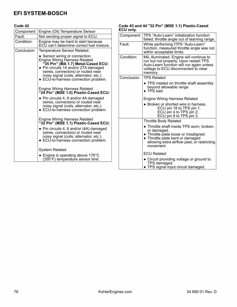
EFI SYSTEM-BOSCH
76 24 690 01 Rev. DKohlerEngines.com
Code 42Component: Engine (Oil) Temperature SensorFault: Not sending proper signal to ECU.Condition: Engine may be hard to start because
ECU can’t determine correct fuel mixture.Conclusion: Temperature Sensor Related.
Sensor wiring or connection.Engine Wiring Harness Related
“35 Pin” (MA 1.7) Metal-Cased ECU: Pin circuits 14 and/or 27A damaged
(wires, connectors) or routed near noisy signal (coils, alternator, etc.).
ECU-to-harness connection problem.
Engine Wiring Harness Related “24 Pin” (MSE 1.0) Plastic-Cased ECU: Pin circuits 4, 6 and/or 4A damaged
(wires, connectors) or routed near noisy signal (coils, alternator, etc.).
ECU-to-harness connection problem.
Engine Wiring Harness Related “32 Pin” (MSE 1.1) Plastic-Cased ECU: Pin circuits 4, 6 and/or (4A) damaged
(wires, connectors) or routed near noisy signal (coils, alternator, etc.).
ECU-to-harness connection problem.
System Related Engine is operating above 176°C
(350°F) temperature sensor limit.
Code 43 and 44 "32 Pin" (MSE 1.1) Plastic-Cased ECU only.Component: TPS “Auto-Learn” initialization function
failed, throttle angle out of learning range.Fault: While performing tTPS “Auto-Learn”
function, measured throttle angle was not within acceptable limits.
Condition: MIL illuminated. Engine will continue to run but not properly. Upon restart TPS Auto-Learn function will run again unless voltage to ECU disconnected to clear memory.
Conclusion: TPS Related TPS rotated on throttle shaft assembly
beyond allowable range. TPS bad.
Engine Wiring Harness Related Broken or shorted wire in harness. ECU pin 18 to TPS pin 1. ECU pin 4 to TPS pin 2. ECU pin 8 to TPS pin 3.Throttle Body Related Throttle shaft inside TPS worn, broken,
or damaged. Throttle plate loose or misaligned. Throttle plate bent or damaged
allowing extra airflow past, or restricting movement.
ECU Related Circuit providing voltage or ground to
TPS damaged. TPS signal input circuit damaged.
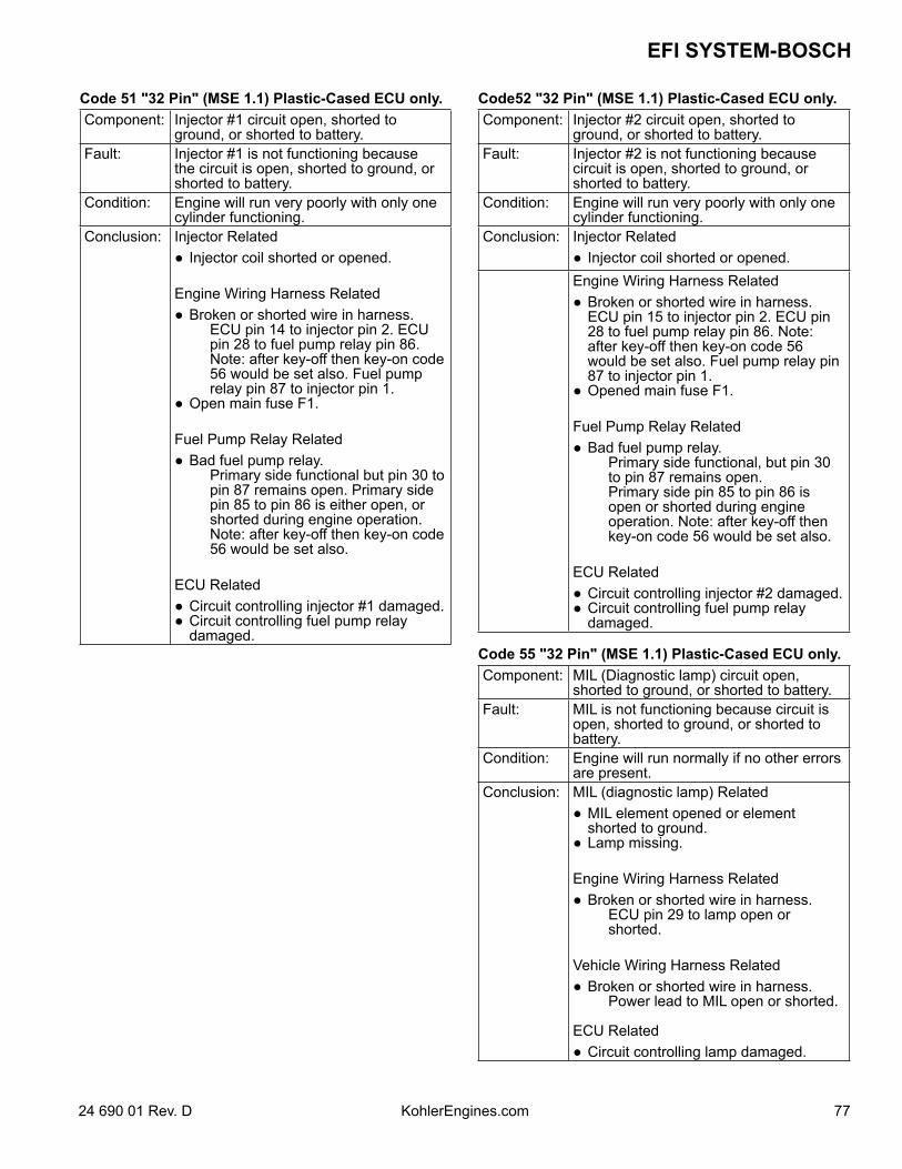
7724 690 01 Rev. D KohlerEngines.com
EFI SYSTEM-BOSCH
Code 51 "32 Pin" (MSE 1.1) Plastic-Cased ECU only.Component: Injector #1 circuit open, shorted to
ground, or shorted to battery.Fault: Injector #1 is not functioning because
the circuit is open, shorted to ground, or shorted to battery.
Condition: Engine will run very poorly with only one cylinder functioning.
Conclusion: Injector Related Injector coil shorted or opened.
Engine Wiring Harness Related Broken or shorted wire in harness. ECU pin 14 to injector pin 2. ECU
pin 28 to fuel pump relay pin 86. Note: after key-off then key-on code 56 would be set also. Fuel pump relay pin 87 to injector pin 1.
Open main fuse F1.
Fuel Pump Relay Related Bad fuel pump relay. Primary side functional but pin 30 to
pin 87 remains open. Primary side pin 85 to pin 86 is either open, or shorted during engine operation. Note: after key-off then key-on code 56 would be set also.
ECU Related Circuit controlling injector #1 damaged. Circuit controlling fuel pump relay
damaged.
Code52 "32 Pin" (MSE 1.1) Plastic-Cased ECU only.Component: Injector #2 circuit open, shorted to
ground, or shorted to battery.Fault: Injector #2 is not functioning because
circuit is open, shorted to ground, or shorted to battery.
Condition: Engine will run very poorly with only one cylinder functioning.
Conclusion: Injector Related Injector coil shorted or opened.Engine Wiring Harness Related Broken or shorted wire in harness.
ECU pin 15 to injector pin 2. ECU pin 28 to fuel pump relay pin 86. Note: after key-off then key-on code 56 would be set also. Fuel pump relay pin 87 to injector pin 1.
Opened main fuse F1.
Fuel Pump Relay Related Bad fuel pump relay. Primary side functional, but pin 30
to pin 87 remains open. Primary side pin 85 to pin 86 is
open or shorted during engine operation. Note: after key-off then key-on code 56 would be set also.
ECU Related Circuit controlling injector #2 damaged. Circuit controlling fuel pump relay
damaged.
Code 55 "32 Pin" (MSE 1.1) Plastic-Cased ECU only.Component: MIL (Diagnostic lamp) circuit open,
shorted to ground, or shorted to battery.Fault: MIL is not functioning because circuit is
open, shorted to ground, or shorted to battery.
Condition: Engine will run normally if no other errors are present.
Conclusion: MIL (diagnostic lamp) Related MIL element opened or element
shorted to ground. Lamp missing.
Engine Wiring Harness Related Broken or shorted wire in harness. ECU pin 29 to lamp open or
shorted.
Vehicle Wiring Harness Related Broken or shorted wire in harness. Power lead to MIL open or shorted.
ECU Related Circuit controlling lamp damaged.
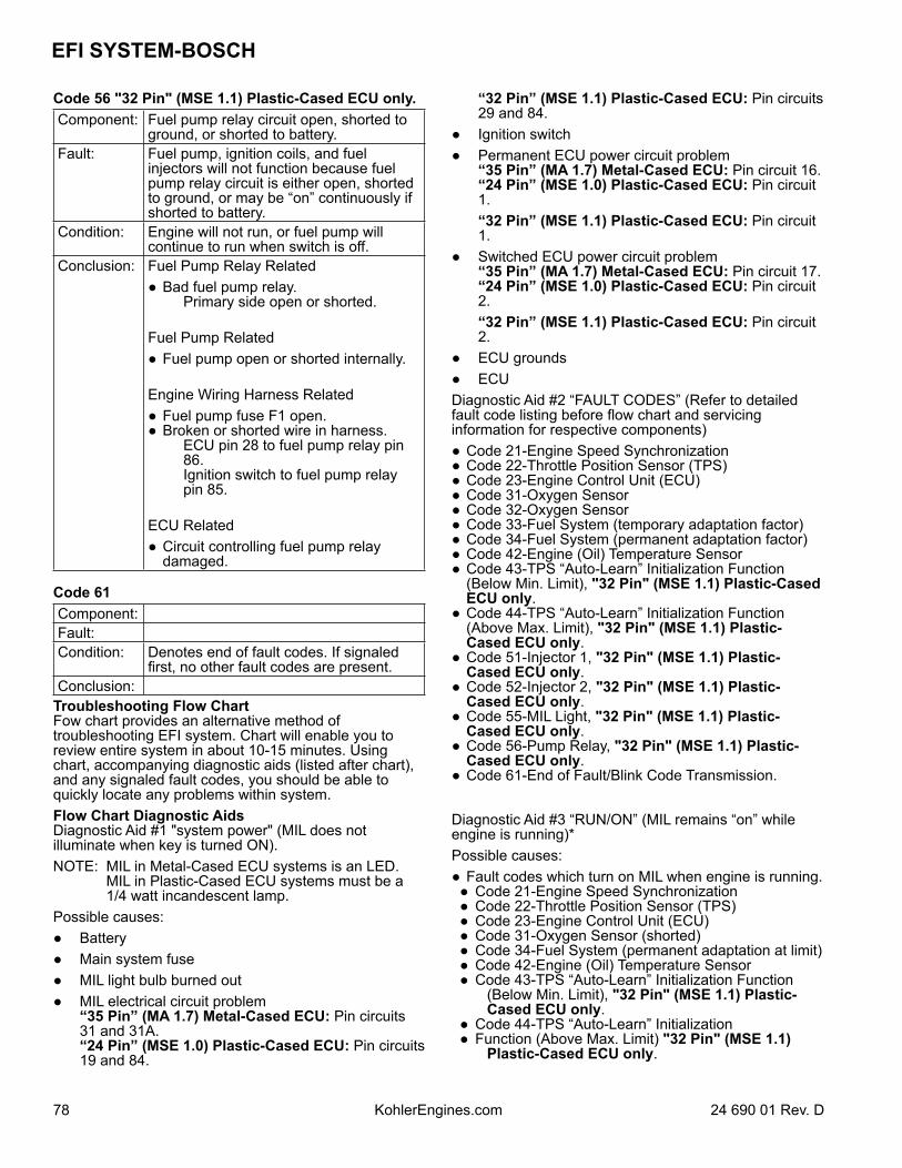
EFI SYSTEM-BOSCH
78 24 690 01 Rev. DKohlerEngines.com
Code 56 "32 Pin" (MSE 1.1) Plastic-Cased ECU only.Component: Fuel pump relay circuit open, shorted to
ground, or shorted to battery.Fault: Fuel pump, ignition coils, and fuel
injectors will not function because fuel pump relay circuit is either open, shorted to ground, or may be “on” continuously if shorted to battery.
Condition: Engine will not run, or fuel pump will continue to run when switch is off.
Conclusion: Fuel Pump Relay Related Bad fuel pump relay. Primary side open or shorted.
Fuel Pump Related Fuel pump open or shorted internally.
Engine Wiring Harness Related Fuel pump fuse F1 open. Broken or shorted wire in harness. ECU pin 28 to fuel pump relay pin
86. Ignition switch to fuel pump relay
pin 85.
ECU Related Circuit controlling fuel pump relay
damaged.
Code 61Component: Fault: Condition: Denotes end of fault codes. If signaled
first, no other fault codes are present.Conclusion:
Troubleshooting Flow ChartFow chart provides an alternative method of troubleshooting EFI system. Chart will enable you to review entire system in about 10-15 minutes. Using chart, accompanying diagnostic aids (listed after chart), and any signaled fault codes, you should be able to quickly locate any problems within system.Flow Chart Diagnostic AidsDiagnostic Aid #1 "system power" (MIL does not illuminate when key is turned ON).NOTE: MIL in Metal-Cased ECU systems is an LED.
MIL in Plastic-Cased ECU systems must be a 1/4 watt incandescent lamp.
Possible causes: Battery Main system fuse MIL light bulb burned out MIL electrical circuit problem
“35 Pin” (MA 1.7) Metal-Cased ECU: Pin circuits 31 and 31A. “24 Pin” (MSE 1.0) Plastic-Cased ECU: Pin circuits 19 and 84.
“32 Pin” (MSE 1.1) Plastic-Cased ECU: Pin circuits 29 and 84.
Ignition switch Permanent ECU power circuit problem
“35 Pin” (MA 1.7) Metal-Cased ECU: Pin circuit 16.“24 Pin” (MSE 1.0) Plastic-Cased ECU: Pin circuit 1.
“32 Pin” (MSE 1.1) Plastic-Cased ECU: Pin circuit 1.
Switched ECU power circuit problem “35 Pin” (MA 1.7) Metal-Cased ECU: Pin circuit 17.“24 Pin” (MSE 1.0) Plastic-Cased ECU: Pin circuit 2.
“32 Pin” (MSE 1.1) Plastic-Cased ECU: Pin circuit 2.
ECU grounds ECUDiagnostic Aid #2 “FAULT CODES” (Refer to detailed fault code listing before flow chart and servicing information for respective components) Code 21-Engine Speed Synchronization Code 22-Throttle Position Sensor (TPS) Code 23-Engine Control Unit (ECU) Code 31-Oxygen Sensor Code 32-Oxygen Sensor Code 33-Fuel System (temporary adaptation factor) Code 34-Fuel System (permanent adaptation factor) Code 42-Engine (Oil) Temperature Sensor Code 43-TPS “Auto-Learn” Initialization Function
(Below Min. Limit), "32 Pin" (MSE 1.1) Plastic-Cased ECU only.
Code 44-TPS “Auto-Learn” Initialization Function (Above Max. Limit), "32 Pin" (MSE 1.1) Plastic-Cased ECU only.
Code 51-Injector 1, "32 Pin" (MSE 1.1) Plastic-Cased ECU only.
Code 52-Injector 2, "32 Pin" (MSE 1.1) Plastic-Cased ECU only.
Code 55-MIL Light, "32 Pin" (MSE 1.1) Plastic-Cased ECU only.
Code 56-Pump Relay, "32 Pin" (MSE 1.1) Plastic-Cased ECU only.
Code 61-End of Fault/Blink Code Transmission.
Diagnostic Aid #3 “RUN/ON” (MIL remains “on” while engine is running)*Possible causes: Fault codes which turn on MIL when engine is running. Code 21-Engine Speed Synchronization Code 22-Throttle Position Sensor (TPS) Code 23-Engine Control Unit (ECU) Code 31-Oxygen Sensor (shorted) Code 34-Fuel System (permanent adaptation at limit) Code 42-Engine (Oil) Temperature Sensor Code 43-TPS “Auto-Learn” Initialization Function
(Below Min. Limit), "32 Pin" (MSE 1.1) Plastic-Cased ECU only.
Code 44-TPS “Auto-Learn” Initialization Function (Above Max. Limit) "32 Pin" (MSE 1.1)
Plastic-Cased ECU only.
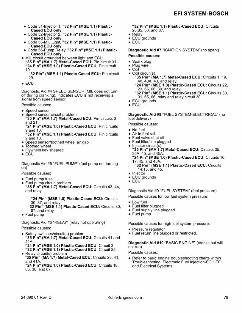
7924 690 01 Rev. D KohlerEngines.com
EFI SYSTEM-BOSCH
Code 51-Injector 1, "32 Pin" (MSE 1.1) Plastic-Cased ECU only.
Code 52-Injector 2, "32 Pin" (MSE 1.1) Plastic-Cased ECU only.
Code 55-MIL Light, "32 Pin" (MSE 1.1) Plastic-Cased ECU only.
Code 56-Pump Relay, "32 Pin" (MSE 1.1) Plastic-Cased ECU only.
MIL circuit grounded between light and ECU. “35 Pin” (MA 1.7) Metal-Cased ECU: Pin circuit 31.“24 Pin” (MSE 1.0) Plastic-Cased ECU: Pin circuit 19.
“32 Pin” (MSE 1.1) Plastic-Cased ECU: Pin circuit 29.
ECU
Diagnostic Aid #4 SPEED SENSOR (MIL does not turn off during cranking). Indicates ECU is not receiving a signal from speed sensor.Possible causes: Speed sensor Speed sensor circuit problem
“35 Pin” (MA 1.7) Metal-Cased ECU: Pin circuits 3 and 21. “24 Pin” (MSE 1.0) Plastic-Cased ECU: Pin circuits 9 and 10.
“32 Pin” (MSE 1.1) Plastic-Cased ECU: Pin circuits 9 and 10.
Speed sensor/toothed wheel air gap Toothed wheel Flywheel key sheared ECU
Diagnostic Aid #5 “FUEL PUMP” (fuel pump not turning on)Possible causes: Fuel pump fuse Fuel pump circuit problem
“35 Pin” (MA 1.7) Metal-Cased ECU: Circuits 43, 44, and relay.
“24 Pin” (MSE 1.0) Plastic-Cased ECU: Circuits 30, 87, and relay.
“32 Pin” (MSE 1.1) Plastic-Cased ECU: Circuits 30, 87, and relay.
Fuel pump
Diagnostic Aid #6 “RELAY” (relay not operating)Possible causes: Safety switches/circuit(s) problem
“35 Pin” (MA 1.7) Metal-Cased ECU: Circuits 41 and 41A. “24 Pin” (MSE 1.0) Plastic-Cased ECU: Circuit 3.
“32 Pin” (MSE 1.1) Plastic-Cased ECU: Circuit 25. Relay circuit(s) problem
“35 Pin” (MA 1.7) Metal-Cased ECU: Circuits 28, 41, and 41A. “24 Pin” (MSE 1.0) Plastic-Cased ECU: Circuits 18, 85, 30, and 87.
“32 Pin” (MSE 1.1) Plastic-Cased ECU: Circuits 28,85, 30, and 87.
Relay ECU grounds ECU
Diagnostic Aid #7 “IGNITION SYSTEM” (no spark)Possible causes: Spark plug Plug wire Coil Coil circuit(s) “35 Pin” (MA 1.7) Metal-Cased ECU: Circuits 1, 19,
40, 40A, 43, and relay. “24 Pin” (MSE 1.0) Plastic-Cased ECU: Circuits 22,
23, 65, 66, 30, and relay. “32 Pin” (MSE 1.1) Plastic-Cased ECU: Circuits 30,
31, 65, 66, relay and relay circuit 30. ECU grounds ECU
Diagnostic Aid #8 “FUEL SYSTEM-ELECTRICAL” (no fuel delivery)Possible causes: No fuel Air in fuel rail Fuel valve shut off Fuel filter/line plugged Injector circuit(s)
“35 Pin” (MA 1.7) Metal-Cased ECU: Circuits 35, 35A, 45, and 45A. “24 Pin” (MSE 1.0) Plastic-Cased ECU: Circuits 16, 17, 45, and 45A.
“32 Pin” (MSE 1.1) Plastic-Cased ECU: Circuits 14,15, and 45.
Injector ECU grounds ECU
Diagnostic Aid #9 “FUEL SYSTEM” (fuel pressure)Possible causes for low fuel system pressure: Low fuel Fuel filter plugged Fuel supply line plugged Fuel pump
Possible causes for high fuel system pressure: Pressure regulator Fuel return line plugged or restricted.
Diagnostic Aid #10 “BASIC ENGINE” (cranks but will not run)Possible causes: Refer to basic engine troubleshooting charts within
Troubleshooting, Electronic Fuel Injection-ECH EFI, and Electrical Systems.
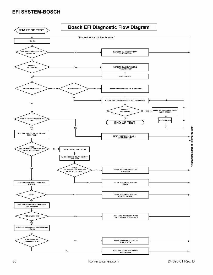
EFI SYSTEM-BOSCH
80 24 690 01 Rev. DKohlerEngines.com
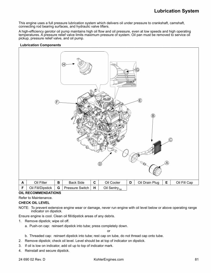
Lubrication System
8124 690 02 Rev. D KohlerEngines.com
This engine uses a full pressure lubrication system which delivers oil under pressure to crankshaft, camshaft, connecting rod bearing surfaces, and hydraulic valve lifters.A high-efficiency gerotor oil pump maintains high oil flow and oil pressure, even at low speeds and high operating temperatures. A pressure relief valve limits maximum pressure of system. Oil pan must be removed to service oil pickup, pressure relief valve, and oil pump.
Lubrication Components
A
HG
B
C
D
EF
A Oil Filter B Back Side C Oil Cooler D Oil Drain Plug E Oil Fill CapF Oil Fill/Dipstick G Pressure Switch H Oil SentryTM
OIL RECOMMENDATIONSRefer to Maintenance.CHECK OIL LEVELNOTE: To prevent extensive engine wear or damage, never run engine with oil level below or above operating range
indicator on dipstick.Ensure engine is cool. Clean oil fill/dipstick areas of any debris.1. Remove dipstick; wipe oil off. a. Push-on cap: reinsert dipstick into tube; press completely down.
or b. Threaded cap: reinsert dipstick into tube; rest cap on tube, do not thread cap onto tube.2. Remove dipstick; check oil level. Level should be at top of indicator on dipstick.3. If oil is low on indicator, add oil up to top of indicator mark.4. Reinstall and secure dipstick.
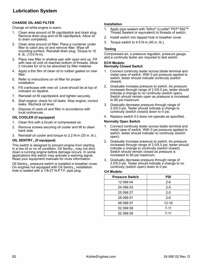
24 690 02 Rev. DKohlerEngines.com82
Lubrication System
CHANGE OIL AND FILTERChange oil while engine is warm.1. Clean area around oil fill cap/dipstick and drain plug.
Remove drain plug and oil fill cap/dipstick. Allow oil to drain completely.
2. Clean area around oil filter. Place a container under filter to catch any oil and remove filter. Wipe off mounting surface. Reinstall drain plug. Torque to 10 ft. lb. (13.6 N·m).
3. Place new filter in shallow pan with open end up. Fill with new oil until oil reaches bottom of threads. Allow 2 minutes for oil to be absorbed by filter material.
4. Apply a thin film of clean oil to rubber gasket on new filter.
5. Refer to instructions on oil filter for proper installation.
6. Fill crankcase with new oil. Level should be at top of indicator on dipstick.
7. Reinstall oil fill cap/dipstick and tighten securely.8. Start engine; check for oil leaks. Stop engine; correct
leaks. Recheck oil level.9. Dispose of used oil and filter in accordance with
local ordinances.OIL COOLER (if equipped)1. Clean fins with a brush or compressed air.2. Remove screws securing oil cooler and tilt to clean
back side.3. Reinstall oil cooler and torque to 2.2 N·m (20 in. lb.).OIL SENTRY™ (if equipped)This switch is designed to prevent engine from starting in a low oil or no oil condition. Oil Sentry™ may not shut down a running engine before damage occurs. In some applications this switch may activate a warning signal. Read your equipment manuals for more information.Oil Sentry™ pressure switch is installed in breather cover. On engines not equipped with Oil Sentry™ installation hole is sealed with a 1/8-27 N.P.T.F. pipe plug.
Installation1. Apply pipe sealant with Teflon® (Loctite® PST® 592™
Thread Sealant or equivalent) to threads of switch.2. Install switch into tapped hole in breather cover.3. Torque switch to 4.5 N·m (40 in. lb.).
TestingCompressed air, a pressure regulator, pressure gauge, and a continuity tester are required to test switch.ECH Models:Normally Closed Switch1. Connect continuity tester across blade terminal and
metal case of switch. With 0 psi pressure applied to switch, tester should indicate continuity (switch closed).
2. Gradually increase pressure to switch. As pressure increases through range of 2.0/5.0 psi, tester should indicate a change to no continuity (switch open).Switch should remain open as pressure is increased to 90 psi maximum.
3. Gradually decrease pressure through range of 2.0/5.0 psi. Tester should indicate a change to continuity (switch closed) down to 0 psi.
4. Replace switch if it does not operate as specified.Normally Open Switch1. Connect continuity tester across blade terminal and
metal case of switch. With 0 psi pressure applied to switch, tester should indicate no continuity (switch open).
2. Gradually increase pressure to switch. As pressure increases through range of 2.0/5.0 psi, tester should indicate a change to continuity (switch closed). Switch should remain closed as pressure is increased to 90 psi maximum.
3. Gradually decrease pressure through range of 2.0/5.0 psi. Tester should indicate a change to no continuity (switch open) down to 0 psi.
CH Models:Pressure Switch PSI
12 099 04 2-624 099 03 2-525 099 27 2-528 099 01 2-648 099 07 12-1652 099 08 7-1152 099 09 7-11
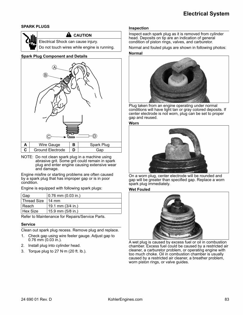
8324 690 01 Rev. D KohlerEngines.com
Electrical System
SPARK PLUGS
CAUTIONElectrical Shock can cause injury.Do not touch wires while engine is running.
Spark Plug Component and Details
B
A
C D
A Wire Gauge B Spark PlugC Ground Electrode D Gap
NOTE: Do not clean spark plug in a machine using abrasive grit. Some grit could remain in spark plug and enter engine causing extensive wear and damage.
Engine misfire or starting problems are often caused by a spark plug that has improper gap or is in poor condition.Engine is equipped with following spark plugs:
Gap 0.76 mm (0.03 in.)Thread Size 14 mmReach 19.1 mm (3/4 in.)Hex Size 15.9 mm (5/8 in.)
Refer to Maintenance for Repairs/Service Parts.
ServiceClean out spark plug recess. Remove plug and replace.1. Check gap using wire feeler gauge. Adjust gap to
0.76 mm (0.03 in.).2. Install plug into cylinder head.3. Torque plug to 27 N·m (20 ft. lb.).
InspectionInspect each spark plug as it is removed from cylinder head. Deposits on tip are an indication of general condition of piston rings, valves, and carburetor.Normal and fouled plugs are shown in following photos:Normal
Plug taken from an engine operating under normal conditions will have light tan or gray colored deposits. If center electrode is not worn, plug can be set to proper gap and reused.Worn
On a worn plug, center electrode will be rounded and gap will be greater than specified gap. Replace a worn spark plug immediately.Wet Fouled
A wet plug is caused by excess fuel or oil in combustion chamber. Excess fuel could be caused by a restricted air cleaner, a carburetor problem, or operating engine with too much choke. Oil in combustion chamber is usually caused by a restricted air cleaner, a breather problem, worn piston rings, or valve guides.
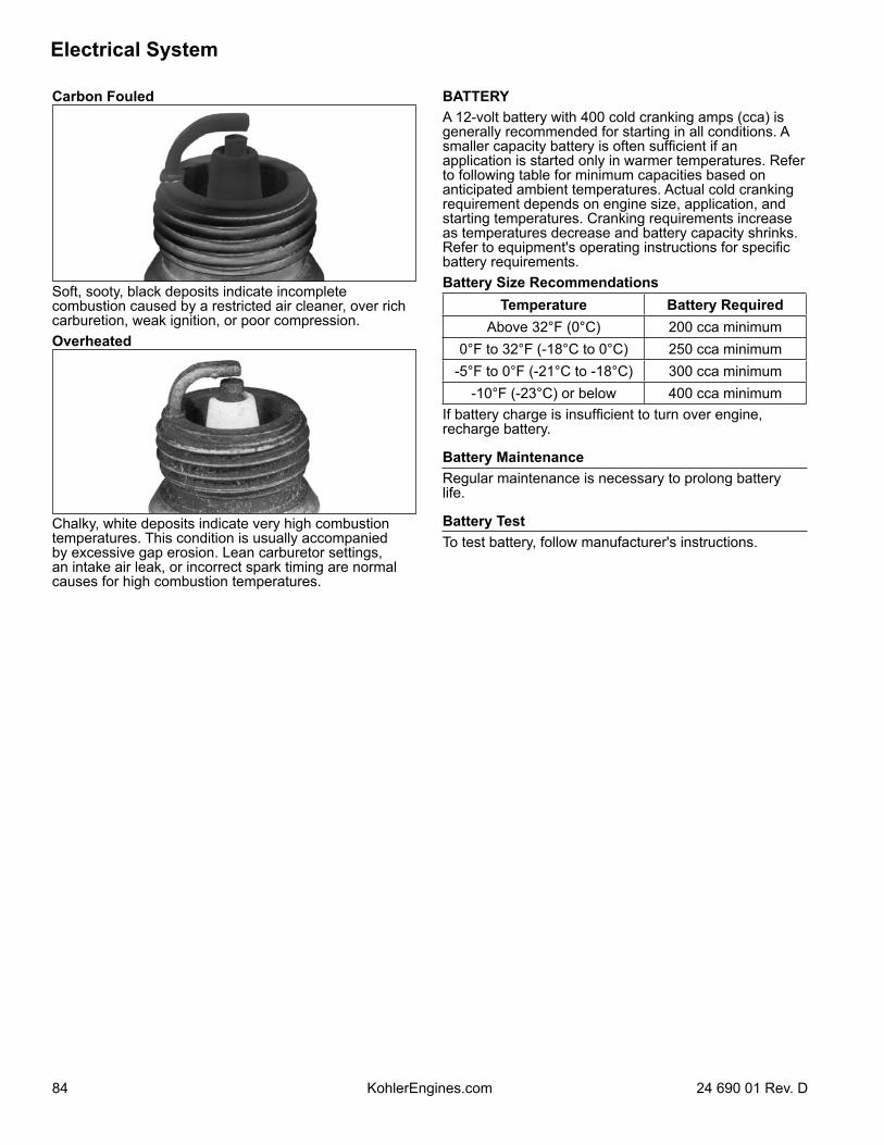
Electrical System
84 24 690 01 Rev. DKohlerEngines.com
Carbon Fouled
Soft, sooty, black deposits indicate incomplete combustion caused by a restricted air cleaner, over rich carburetion, weak ignition, or poor compression.Overheated
Chalky, white deposits indicate very high combustion temperatures. This condition is usually accompanied by excessive gap erosion. Lean carburetor settings, an intake air leak, or incorrect spark timing are normal causes for high combustion temperatures.
BATTERYA 12-volt battery with 400 cold cranking amps (cca) is generally recommended for starting in all conditions. A smaller capacity battery is often sufficient if an application is started only in warmer temperatures. Refer to following table for minimum capacities based on anticipated ambient temperatures. Actual cold cranking requirement depends on engine size, application, and starting temperatures. Cranking requirements increase as temperatures decrease and battery capacity shrinks. Refer to equipment's operating instructions for specific battery requirements.Battery Size Recommendations
Temperature Battery RequiredAbove 32°F (0°C) 200 cca minimum
0°F to 32°F (-18°C to 0°C) 250 cca minimum-5°F to 0°F (-21°C to -18°C) 300 cca minimum
-10°F (-23°C) or below 400 cca minimumIf battery charge is insufficient to turn over engine, recharge battery.
Battery MaintenanceRegular maintenance is necessary to prolong battery life.
Battery TestTo test battery, follow manufacturer's instructions.
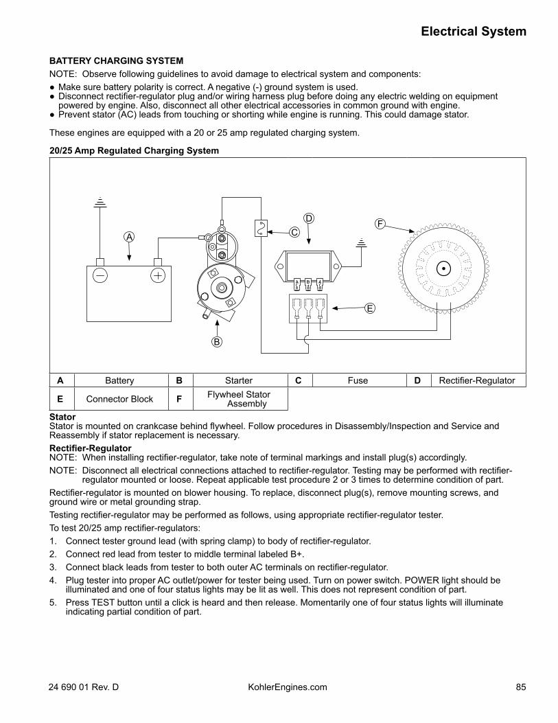
8524 690 01 Rev. D KohlerEngines.com
Electrical System
BATTERY CHARGING SYSTEMNOTE: Observe following guidelines to avoid damage to electrical system and components: Make sure battery polarity is correct. A negative (-) ground system is used. Disconnect rectifier-regulator plug and/or wiring harness plug before doing any electric welding on equipment
powered by engine. Also, disconnect all other electrical accessories in common ground with engine. Prevent stator (AC) leads from touching or shorting while engine is running. This could damage stator.
These engines are equipped with a 20 or 25 amp regulated charging system.
20/25 Amp Regulated Charging System
B
C
E
FA
D
A Battery B Starter C Fuse D Rectifier-Regulator
E Connector Block F Flywheel Stator Assembly
StatorStator is mounted on crankcase behind flywheel. Follow procedures in Disassembly/Inspection and Service and Reassembly if stator replacement is necessary.Rectifier-RegulatorNOTE: When installing rectifier-regulator, take note of terminal markings and install plug(s) accordingly.NOTE: Disconnect all electrical connections attached to rectifier-regulator. Testing may be performed with rectifier-
regulator mounted or loose. Repeat applicable test procedure 2 or 3 times to determine condition of part.Rectifier-regulator is mounted on blower housing. To replace, disconnect plug(s), remove mounting screws, and ground wire or metal grounding strap.Testing rectifier-regulator may be performed as follows, using appropriate rectifier-regulator tester.To test 20/25 amp rectifier-regulators:1. Connect tester ground lead (with spring clamp) to body of rectifier-regulator.2. Connect red lead from tester to middle terminal labeled B+.3. Connect black leads from tester to both outer AC terminals on rectifier-regulator.4. Plug tester into proper AC outlet/power for tester being used. Turn on power switch. POWER light should be
illuminated and one of four status lights may be lit as well. This does not represent condition of part.5. Press TEST button until a click is heard and then release. Momentarily one of four status lights will illuminate
indicating partial condition of part.
Electrical System
86 24 690 01 Rev. DKohlerEngines.com
Condition Conclusion20/25 amp
OK (green) light comes on and stays steady. Disconnect tester black lead attached to 1 AC terminal and reconnect it to other AC terminal. Repeat test. If OK (green) light comes on again, part is good and may be used.
NOTE: A flashing LOW light can also occur as a result of an inadequate ground lead connection. Make certain connection location is clean and clamp is secure.
Other lights come on.
Rectifier-regulator is faulty and should not be used.
Troubleshooting Guide20/25 Amp Battery Charging SystemNOTE: Always zero ohmmeter on each scale before
testing to ensure accurate readings. Voltage tests should be made with engine running at 3600 RPM - no load. Battery must be good and fully charged.
When problems occur in keeping battery charged or battery charges at too high a rate, problem can usually be found somewhere in charging system or with battery.To test charging system for no charge to battery:1. Insert an ammeter in B+ lead from rectifier-regulator.
With engine running at 3600 RPM and B+ (at terminal on rectifier-regulator) to ground using a DC voltmeter.
If voltage is 13.8 volts or more, place a minimum load of 5 amps (turn on lights if 60 watts or more, or place a 2.5 ohm, 100 watt resistor across battery terminals) on battery to reduce voltage. Observe ammeter.
Condition ConclusionCharge rate increases when load is applied.
Charging system is OK and battery was fully charged.
Charge rate does not increase when load is applied.
Test stator and rectifier-regulator (steps 2 and 3).
2. Remove connector from rectifier-regulator. With engine running at 3600 RPM, measure AC voltage across stator leads using an AC voltmeter.
Condition ConclusionVoltage is 28 volts or more.
Stator is OK. Rectifier-regulator is faulty; replace.
Voltage is less than 28 volts.
Stator is faulty; replace. Test stator further using an ohmmeter (steps 3 and 4).
3. With engine stopped, measure resistance across stator leads using an ohmmeter.
Condition ConclusionResistance is 0.064/0.2 ohms.
Stator is OK.
Resistance is 0 ohms. Stator is shorted; replace.Resistance is infinity ohms.
Stator is open; replace.
4. With engine stopped, measure resistance from each stator lead to ground using an ohmmeter.
Condition ConclusionResistance is infinity ohms (no continuity).
Stator is OK (not shorted to ground).
Resistance (or continuity) measured.
Stator leads are shorted to ground; replace.
To test charging system for battery continuously charging at high rate:1. With engine running at 3600 RPM, measure voltage
from B+ lead to ground using a DC voltmeter.
Condition ConclusionVoltage is 14.7 volts or less.
Charging system is OK. Battery is unable to hold charge; service or replace.
Voltage is more than 14.7 volts.
Faulty rectifier-regulator; replace.
8724 690 01 Rev. D KohlerEngines.com
Electrical System
FUSESThis engine has 3 blade type automotive fuses. Replacement fuses must have same rating as blown fuse. Use fuse chart below to determine correct fuse.
Wire Color Fuse Rating2 Purple Wires 30-amp Fuse
1 Red Wire w/ Black Stripe1 Red Wire w/ White Stripe 10-amp Fuse
2 Red Wires 10-amp Fuse
Fuse Replacement1. Shut engine off and remove key.2. Locate fuse holders.3. Remove fuse cover and pull out fuse.4. Inspect fuse for a solid fusible link or a broken
fusible link. Replace fuse if fusible link is broken. If you are not sure if fusible link is broken, replace fuse.
5. Insert fuse into fuse holder until it is seated properly. Install fuse cover.
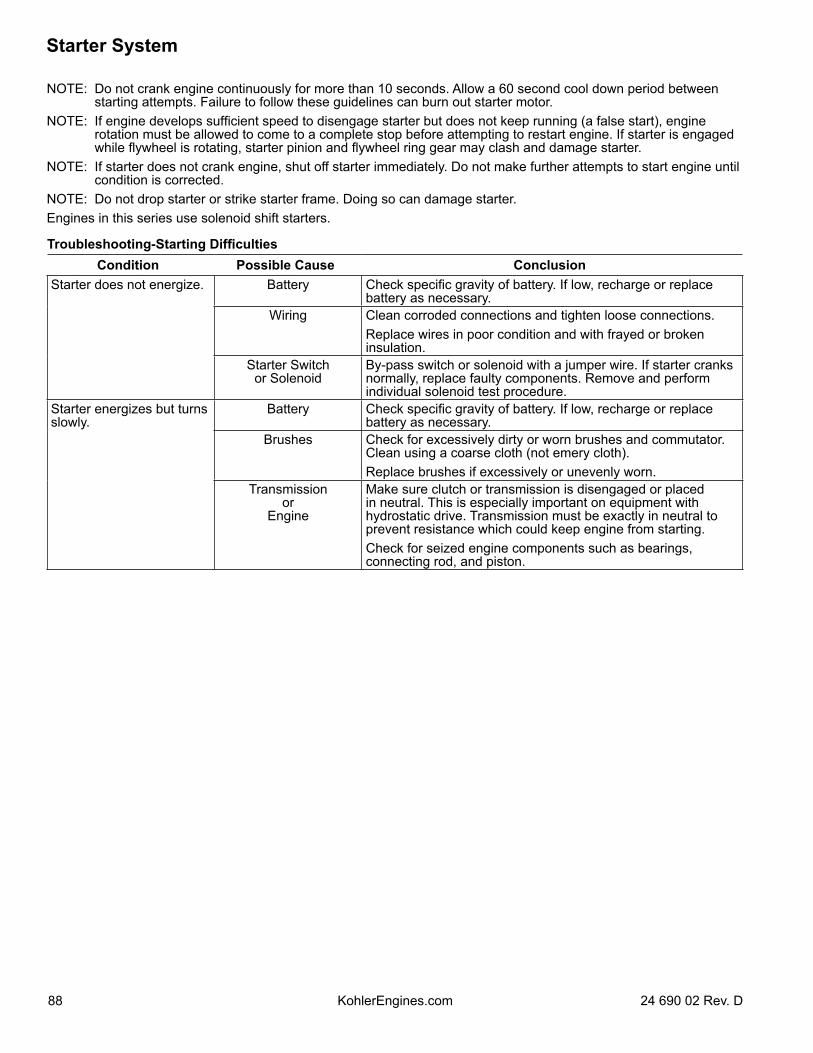
Starter System
88 24 690 02 Rev. DKohlerEngines.com
NOTE: Do not crank engine continuously for more than 10 seconds. Allow a 60 second cool down period between starting attempts. Failure to follow these guidelines can burn out starter motor.
NOTE: If engine develops sufficient speed to disengage starter but does not keep running (a false start), engine rotation must be allowed to come to a complete stop before attempting to restart engine. If starter is engaged while flywheel is rotating, starter pinion and flywheel ring gear may clash and damage starter.
NOTE: If starter does not crank engine, shut off starter immediately. Do not make further attempts to start engine until condition is corrected.
NOTE: Do not drop starter or strike starter frame. Doing so can damage starter.Engines in this series use solenoid shift starters.
Troubleshooting-Starting DifficultiesCondition Possible Cause Conclusion
Starter does not energize. Battery Check specific gravity of battery. If low, recharge or replace battery as necessary.
Wiring Clean corroded connections and tighten loose connections.Replace wires in poor condition and with frayed or broken insulation.
Starter Switchor Solenoid
By-pass switch or solenoid with a jumper wire. If starter cranks normally, replace faulty components. Remove and perform individual solenoid test procedure.
Starter energizes but turns slowly.
Battery Check specific gravity of battery. If low, recharge or replace battery as necessary.
Brushes Check for excessively dirty or worn brushes and commutator. Clean using a coarse cloth (not emery cloth).Replace brushes if excessively or unevenly worn.
Transmissionor
Engine
Make sure clutch or transmission is disengaged or placed in neutral. This is especially important on equipment with hydrostatic drive. Transmission must be exactly in neutral to prevent resistance which could keep engine from starting.Check for seized engine components such as bearings, connecting rod, and piston.
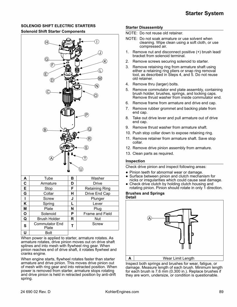
8924 690 02 Rev. D KohlerEngines.com
Starter System
SOLENOID SHIFT ELECTRIC STARTERSSolenoid Shift Starter Components
A
B
U
T
S
R
Q
P
O
N
M
L
K
J
IH
GF
ED
C
A Tube B WasherC Armature D DriveE Stop F Retaining RingG Collar H Drive End CapI Screw J PlungerK Spring L LeverM Plate N PlugO Solenoid P Frame and FieldQ Brush Holder R Nut
S Commutator EndPlate T Screw
U BoltWhen power is applied to starter, armature rotates. As armature rotates, drive pinion moves out on drive shaft splines and into mesh with flywheel ring gear. When pinion reaches end of drive shaft, it rotates flywheel and cranks engine.When engine starts, flywheel rotates faster than starter armature and drive pinion. This moves drive pinion out of mesh with ring gear and into retracted position. When power is removed from starter, armature stops rotating and drive pinion is held in retracted position by anti-drift spring.
Starter DisassemblyNOTE: Do not reuse old retainer.NOTE: Do not soak armature or use solvent when
cleaning. Wipe clean using a soft cloth, or use compressed air.
1. Remove nut and disconnect positive (+) brush lead/bracket from solenoid terminal.
2. Remove screws securing solenoid to starter.3. Remove retaining ring from armature shaft using
either a retaining ring pliers or snap ring removal tool, as described in Steps 4, and 5. Do not reuse old retainer.
4. Remove thru (larger) bolts.5. Remove commutator end plate assembly, containing
brush holder, brushes, springs, and locking caps. Remove thrust washer from inside commutator end.
6. Remove frame from armature and drive end cap.7. Remove rubber grommet and backing plate from
end cap.8. Take out drive lever and pull armature out of drive
end cap.9. Remove thrust washer from armature shaft.10. Push stop collar down to expose retaining ring.11. Remove retainer from armature shaft. Save stop
collar.12. Remove drive pinion assembly from armature.13. Clean parts as required.
InspectionCheck drive pinion and inspect following areas: Pinion teeth for abnormal wear or damage. Surface between pinion and clutch mechanism for
nicks or irregularities which could cause seal damage. Check drive clutch by holding clutch housing and
rotating pinion. Pinion should rotate in only 1 direction.Brushes and SpringsDetail
A
A Wear Limit LengthInspect both springs and brushes for wear, fatigue, or damage. Measure length of each brush. Minimum length for each brush is 7.6 mm (0.300 in.). Replace brushes if they are worn, undersize, or condition is questionable.
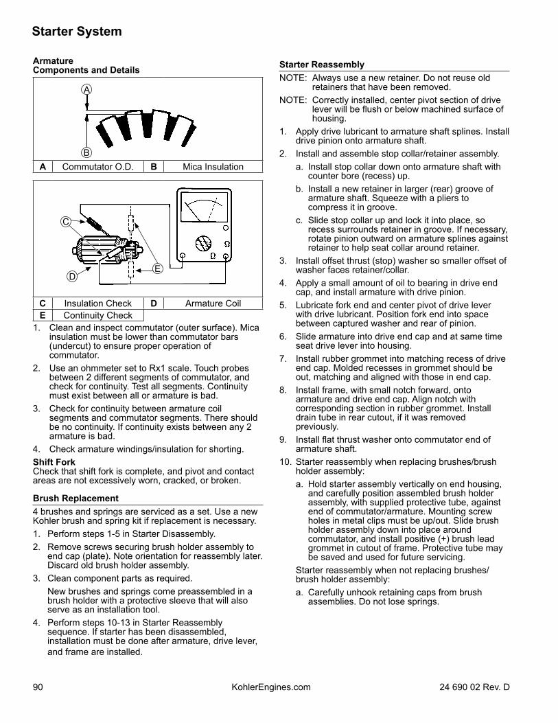
Starter System
90 24 690 02 Rev. DKohlerEngines.com
ArmatureComponents and Details
A
BA Commutator O.D. B Mica Insulation
DE
C
C Insulation Check D Armature CoilE Continuity Check
1. Clean and inspect commutator (outer surface). Mica insulation must be lower than commutator bars (undercut) to ensure proper operation of commutator.
2. Use an ohmmeter set to Rx1 scale. Touch probes between 2 different segments of commutator, and check for continuity. Test all segments. Continuity must exist between all or armature is bad.
3. Check for continuity between armature coil segments and commutator segments. There should be no continuity. If continuity exists between any 2 armature is bad.
4. Check armature windings/insulation for shorting.Shift ForkCheck that shift fork is complete, and pivot and contact areas are not excessively worn, cracked, or broken.
Brush Replacement4 brushes and springs are serviced as a set. Use a new Kohler brush and spring kit if replacement is necessary.1. Perform steps 1-5 in Starter Disassembly.2. Remove screws securing brush holder assembly to
end cap (plate). Note orientation for reassembly later. Discard old brush holder assembly.
3. Clean component parts as required. New brushes and springs come preassembled in a
brush holder with a protective sleeve that will also serve as an installation tool.
4. Perform steps 10-13 in Starter Reassembly sequence. If starter has been disassembled, installation must be done after armature, drive lever, and frame are installed.
Starter ReassemblyNOTE: Always use a new retainer. Do not reuse old
retainers that have been removed.NOTE: Correctly installed, center pivot section of drive
lever will be flush or below machined surface of housing.
1. Apply drive lubricant to armature shaft splines. Install drive pinion onto armature shaft.
2. Install and assemble stop collar/retainer assembly. a. Install stop collar down onto armature shaft with
counter bore (recess) up. b. Install a new retainer in larger (rear) groove of
armature shaft. Squeeze with a pliers to compress it in groove.
c. Slide stop collar up and lock it into place, so recess surrounds retainer in groove. If necessary, rotate pinion outward on armature splines against retainer to help seat collar around retainer.
3. Install offset thrust (stop) washer so smaller offset of washer faces retainer/collar.
4. Apply a small amount of oil to bearing in drive end cap, and install armature with drive pinion.
5. Lubricate fork end and center pivot of drive lever with drive lubricant. Position fork end into space between captured washer and rear of pinion.
6. Slide armature into drive end cap and at same time seat drive lever into housing.
7. Install rubber grommet into matching recess of drive end cap. Molded recesses in grommet should be out, matching and aligned with those in end cap.
8. Install frame, with small notch forward, onto armature and drive end cap. Align notch with corresponding section in rubber grommet. Install drain tube in rear cutout, if it was removed previously.
9. Install flat thrust washer onto commutator end of armature shaft.
10. Starter reassembly when replacing brushes/brush holder assembly:
a. Hold starter assembly vertically on end housing, and carefully position assembled brush holder assembly, with supplied protective tube, against end of commutator/armature. Mounting screw holes in metal clips must be up/out. Slide brush holder assembly down into place around commutator, and install positive (+) brush lead grommet in cutout of frame. Protective tube may be saved and used for future servicing.
Starter reassembly when not replacing brushes/brush holder assembly:
a. Carefully unhook retaining caps from brush assemblies. Do not lose springs.
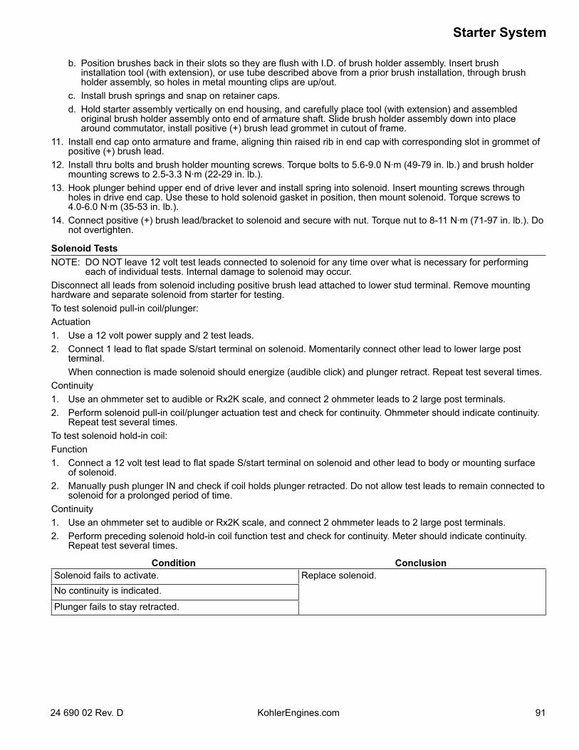
9124 690 02 Rev. D KohlerEngines.com
Starter System
b. Position brushes back in their slots so they are flush with I.D. of brush holder assembly. Insert brush installation tool (with extension), or use tube described above from a prior brush installation, through brush holder assembly, so holes in metal mounting clips are up/out.
c. Install brush springs and snap on retainer caps. d. Hold starter assembly vertically on end housing, and carefully place tool (with extension) and assembled
original brush holder assembly onto end of armature shaft. Slide brush holder assembly down into place around commutator, install positive (+) brush lead grommet in cutout of frame.
11. Install end cap onto armature and frame, aligning thin raised rib in end cap with corresponding slot in grommet of positive (+) brush lead.
12. Install thru bolts and brush holder mounting screws. Torque bolts to 5.6-9.0 N·m (49-79 in. lb.) and brush holder mounting screws to 2.5-3.3 N·m (22-29 in. lb.).
13. Hook plunger behind upper end of drive lever and install spring into solenoid. Insert mounting screws through holes in drive end cap. Use these to hold solenoid gasket in position, then mount solenoid. Torque screws to 4.0-6.0 N·m (35-53 in. lb.).
14. Connect positive (+) brush lead/bracket to solenoid and secure with nut. Torque nut to 8-11 N·m (71-97 in. lb.). Do not overtighten.
Solenoid TestsNOTE: DO NOT leave 12 volt test leads connected to solenoid for any time over what is necessary for performing
each of individual tests. Internal damage to solenoid may occur.Disconnect all leads from solenoid including positive brush lead attached to lower stud terminal. Remove mounting hardware and separate solenoid from starter for testing.To test solenoid pull-in coil/plunger:Actuation1. Use a 12 volt power supply and 2 test leads.2. Connect 1 lead to flat spade S/start terminal on solenoid. Momentarily connect other lead to lower large post
terminal. When connection is made solenoid should energize (audible click) and plunger retract. Repeat test several times.Continuity1. Use an ohmmeter set to audible or Rx2K scale, and connect 2 ohmmeter leads to 2 large post terminals.2. Perform solenoid pull-in coil/plunger actuation test and check for continuity. Ohmmeter should indicate continuity.
Repeat test several times.To test solenoid hold-in coil:Function1. Connect a 12 volt test lead to flat spade S/start terminal on solenoid and other lead to body or mounting surface
of solenoid.2. Manually push plunger IN and check if coil holds plunger retracted. Do not allow test leads to remain connected to
solenoid for a prolonged period of time. Continuity1. Use an ohmmeter set to audible or Rx2K scale, and connect 2 ohmmeter leads to 2 large post terminals. 2. Perform preceding solenoid hold-in coil function test and check for continuity. Meter should indicate continuity.
Repeat test several times.
Condition ConclusionSolenoid fails to activate. Replace solenoid.No continuity is indicated.
Plunger fails to stay retracted.
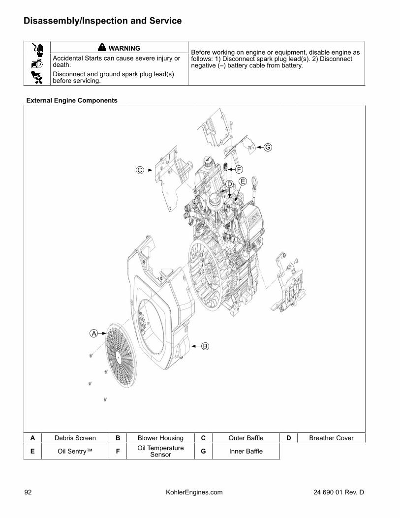
WARNING Before working on engine or equipment, disable engine as follows: 1) Disconnect spark plug lead(s). 2) Disconnect negative (–) battery cable from battery.
Accidental Starts can cause severe injury or death.Disconnect and ground spark plug lead(s) before servicing.
External Engine Components
A
C
D
G
B
F
E
A Debris Screen B Blower Housing C Outer Baffle D Breather Cover
E Oil Sentry™ F Oil Temperature Sensor G Inner Baffle
Disassembly/Inspection and Service
92 24 690 01 Rev. DKohlerEngines.com
Clean all parts thoroughly as engine is disassembled. Only clean parts can be accurately inspected and gauged for wear or damage. There are many commercially available cleaners that will quickly remove grease, oil, and grime from engine parts. When such a cleaner is used, follow manufacturer’s instructions and safety precautions carefully.Make sure all traces of cleaner are removed before engine is reassembled and placed into operation. Even small amounts of these cleaners can quickly break down lubricating properties of engine oil.
Disconnect Spark Plug LeadsNOTE: Pull on boot only, to prevent damage to spark
plug lead.Disconnect leads from spark plugs.
Drain Oil from Crankcase and Remove Oil FilterNOTE: Some models are equipped with an oil drain
valve.1. Remove oil fill cap, dipstick, and 1 oil drain plug.2. Allow ample time for oil to drain from crankcase and
oil filter.3. Remove and discard oil filter.
Remove Oil Cooler1. Use an 8 mm Allen wrench to remove oil filter
threaded nipple.2. Separate filter adapter from closure plate, leaving oil
lines attached. Remove screws mounting oil cooler to blower housing, then remove cooler, lines, and filter adapter as an assembly.
Remove Muffler1. Remove exhaust system and attaching hardware
from engine. On engines equipped with a port liner, remove it now.
2. Remove oxygen sensor and disconnect connector from wire harness.
Remove Air Cleaner AssemblyHeavy Duty Air Cleaner 1. Remove nuts securing air cleaner assembly to
throttle body.2. Remove screws securing air cleaner assembly to air
cleaner bracket and remove air cleaner assembly.Low-Profile Air Cleaner (Optional)1. Loosen retaining knob and remove cover. 2. Remove wing nut from element cover.3. Remove element cover, air cleaner element with
precleaner, and stud seal.4. Remove nuts.5. Remove screws securing base and then remove
base.
Remove Throttle Control Panel1. Disconnect throttle control cable.2. Remove screws securing throttle control panel and
remove panel from blower housing.
Disassembly/Inspection and Service
9324 690 01 Rev. D KohlerEngines.com
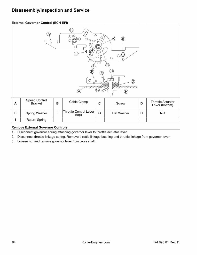
External Governor Control (ECH EFI)
D
AB
C B
I
FF
D
E C
A G H
ASpeed Control
Bracket B Cable Clamp C Screw D Throttle Actuator Lever (bottom)
E Spring Washer F Throttle Control Lever (top) G Flat Washer H Nut
I Return Spring
Remove External Governor Controls1. Disconnect governor spring attaching governor lever to throttle actuator lever.2. Disconnect throttle linkage spring. Remove throttle linkage bushing and throttle linkage from governor lever.5. Loosen nut and remove governor lever from cross shaft.
Disassembly/Inspection and Service
94 24 690 01 Rev. DKohlerEngines.com
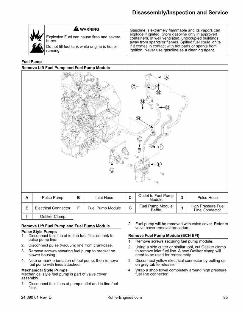
WARNING Gasoline is extremely flammable and its vapors can explode if ignited. Store gasoline only in approved containers, in well ventilated, unoccupied buildings, away from sparks or flames. Spilled fuel could ignite if it comes in contact with hot parts or sparks from ignition. Never use gasoline as a cleaning agent.
Explosive Fuel can cause fires and severe burns.Do not fill fuel tank while engine is hot or running.
Fuel PumpRemove Lift Fuel Pump and Fuel Pump Module
B
G
A
E
G
C
D
F
H
I
A Pulse Pump B Inlet Hose C Outlet to Fuel Pump Module D Pulse Hose
E Electrical Connector F Fuel Pump Module G Fuel Pump Module Baffle H High Pressure Fuel
Line ConnectorI Oetiker Clamp
Remove Lift Fuel Pump and Fuel Pump ModulePulse Style Pumps1. Disconnect fuel line at in-line fuel filter on tank to
pulse pump line.2. Disconnect pulse (vacuum) line from crankcase.3. Remove screws securing fuel pump to bracket on
blower housing.4. Note or mark orientation of fuel pump, then remove
fuel pump with lines attached.Mechanical Style PumpsMechanical style fuel pump is part of valve cover assembly.1. Disconnect fuel lines at pump outlet and in-line fuel
filter.
2. Fuel pump will be removed with valve cover. Refer to valve cover removal procedure.
Remove Fuel Pump Module (ECH EFI)1. Remove screws securing fuel pump module.2. Using a side cutter or similar tool, cut Oetiker clamp
to remove inlet fuel line. A new Oetiker clamp will need to be used for reassembly.
3. Disconnect yellow electrical connector by pulling up on grey tab to release.
4. Wrap a shop towel completely around high pressure fuel line connector.
Disassembly/Inspection and Service
9524 690 01 Rev. D KohlerEngines.com
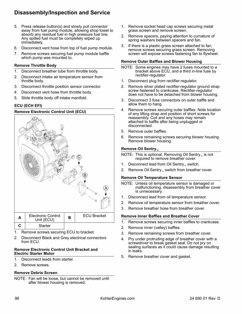
5. Press release button(s) and slowly pull connector away from fuel pump module, allowing shop towel to absorb any residual fuel in high pressure fuel line. Any spilled fuel must be completely wiped up immediately.
6. Disconnect vent hose from top of fuel pump module.7. Remove screws securing fuel pump module baffle
which pump was mounted to.
Remove Throttle Body1. Disconnect breather tube from throttle body.2. Disconnect intake air temperature sensor from
throttle body.3. Disconnect throttle position sensor connector.4. Disconnect vent hose from throttle body.5. Slide throttle body off intake manifold.
ECU (ECH EFI)Remove Electronic Control Unit (ECU)
B
A
C
A Electronic Control Unit (ECU) B ECU Bracket
C Starter1. Remove screws securing ECU to bracket.2. Disconnect Black and Grey electrical connectors
from ECU.
Remove Electronic Control Unit Bracket and Electric Starter Motor1. Disconnect leads from starter.2. Remove screws.
Remove Debris ScreenNOTE: Fan will be loose, but cannot be removed until
after blower housing is removed.
1. Remove socket head cap screws securing metal grass screen and remove screen.
2. Remove spacers, paying attention to curvature of spring washers between spacers and fan.
3. If there is a plastic grass screen attached to fan, remove screws securing grass screen. Removing screen will expose screws fastening fan to flywheel.
Remove Outer Baffles and Blower HousingNOTE: Some engines may have 2 fuses mounted to a
bracket above ECU, and a third in-line fuse by rectifier-regulator.
1. Disconnect plug from rectifier-regulator.2. Remove silver plated rectifier-regulator ground strap
screw fastened to crankcase. Rectifier-regulator does not have to be detached from blower housing.
3. Disconnect 3 fuse connectors on outer baffle and allow them to hang.
4. Remove screws securing outer baffles. Note location of any lifting strap and position of short screws for reassembly. Coil and any hoses may remain attached to baffle after being unplugged or disconnected.
5. Remove outer baffles.6. Remove remaining screws securing blower housing.
Remove blower housing.
Remove Oil Sentry™
NOTE: This is optional. Removing Oil Sentry™ is not required to remove breather cover.
1. Disconnect lead from Oil Sentry™ switch.2. Remove Oil Sentry™ switch from breather cover.
Remove Oil Temperature SensorNOTE: Unless oil temperature sensor is damaged or
malfunctioning, disassembly from breather cover is unnecessary.
1. Disconnect lead from oil temperature sensor.2. Remove oil temperature sensor from breather cover.3. Remove breather hose from breather cover.
Remove Inner Baffles and Breather Cover1. Remove screws securing inner baffles to crankcase.2. Remove inner (valley) baffles.3. Remove remaining screws from breather cover.4. Pry under protruding edge of breather cover with a
screwdriver to break gasket seal. Do not pry on sealing surfaces as it could cause damage resulting in leaks.
5. Remove breather cover and gasket.
Disassembly/Inspection and Service
96 24 690 01 Rev. DKohlerEngines.com
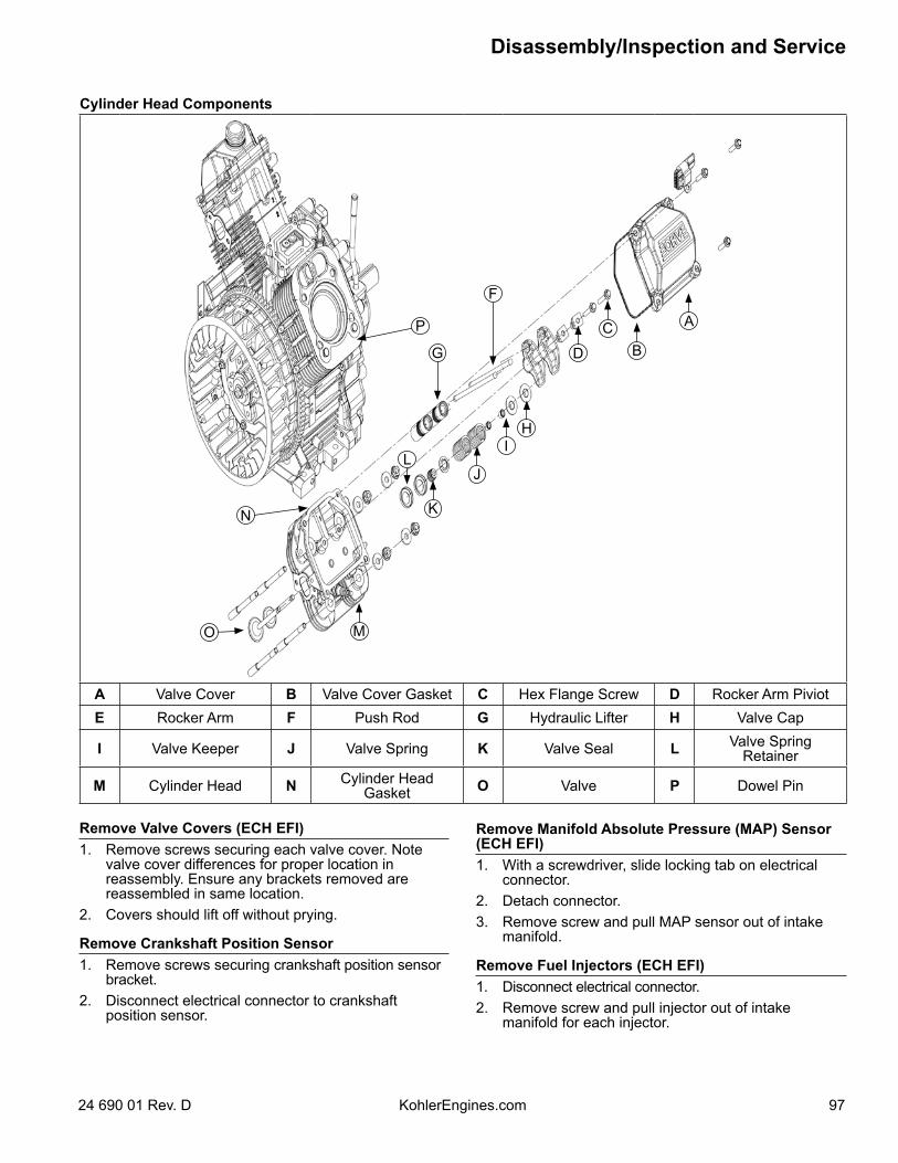
Cylinder Head Components
A
BC
D
HI
L
G
F
J
M
KN
O
P
A Valve Cover B Valve Cover Gasket C Hex Flange Screw D Rocker Arm PiviotE Rocker Arm F Push Rod G Hydraulic Lifter H Valve Cap
I Valve Keeper J Valve Spring K Valve Seal L Valve Spring Retainer
M Cylinder Head N Cylinder Head Gasket O Valve P Dowel Pin
Remove Valve Covers (ECH EFI)1. Remove screws securing each valve cover. Note
valve cover differences for proper location in reassembly. Ensure any brackets removed are reassembled in same location.
2. Covers should lift off without prying.
Remove Crankshaft Position Sensor1. Remove screws securing crankshaft position sensor
bracket.2. Disconnect electrical connector to crankshaft
position sensor.
Remove Manifold Absolute Pressure (MAP) Sensor (ECH EFI)1. With a screwdriver, slide locking tab on electrical
connector.2. Detach connector.3. Remove screw and pull MAP sensor out of intake
manifold.
Remove Fuel Injectors (ECH EFI)1. Disconnect electrical connector.2. Remove screw and pull injector out of intake
manifold for each injector.
Disassembly/Inspection and Service
9724 690 01 Rev. D KohlerEngines.com
3. When removed, pull metal retaining clip connecting fuel injector to fuel injector cap. There may be some fuel left in line. Any spilled fuel must be cleaned up immediately.
Remove Intake Manifold1. Remove screw securing a ring terminal which is part of wiring harness.2. Remove screws securing intake manifold to cylinder heads. Note which screws hold wiring clamp. 3. Unclasp wiring harness from clip using a screwdriver.4. Remove intake manifold and intake manifold gaskets.5. Leave wiring harness attached to manifold.
Remove Spark PlugsRemove spark plug from each cylinder head.
Remove Cylinder Heads and Hydraulic LiftersNOTE: Cylinder heads are retained using either screws or nuts and washers on studs. Do not interchange or mix
components.1. Remove screws or nuts and washers securing each cylinder head. Discard screws or nuts and washers once
removed. Do not reuse. Studs (if present) should only be removed if damaged or if cylinder reconditioning is necessary. Once removed, they must be replaced.
2. Mark location of push rods as either intake or exhaust and cylinder 1 or 2. Push rods should always be reinstalled in same positions.
3. Carefully remove push rods, cylinder heads, and head gaskets.4. Remove lifters from lifter bores. Use a hydraulic lifter tool. Do not use a magnet to remove lifters. Mark lifters by
location, as either intake or exhaust, and cylinder 1 or 2. Hydraulic lifters should always be reinstalled in same position.
InspectionCheck base surface of hydraulic lifters for wear or damage. If lifters need to be replaced, apply a liberal coating of Kohler lubricant (see Tools and Aids) to base of each new lifter before it is installed.Bleeding LiftersTo prevent a possible bent push rod or broken rocker arm, it is important to bleed any excess oil out of lifters before they are installed.1. Cut a 50-75 mm (2-3 in.) piece from end of an old push rod and chuck it in a drill press.2. Lay a rag or shop towel on table of drill press and place lifter, open end up, on towel.3. Lower chucked push rod until it contacts plunger in lifter. Slowly pump plunger 2 or 3 times to force oil out of feed
hole in side of lifter.
Disassemble Cylinder HeadsNOTE: These engines use valve stem seals on intake and exhaust valves. Use a new seal whenever valve is
removed or if seal is deteriorated or damaged in any way. Never reuse an old seal.1. Remove screws, rocker arm pivots and rocker arms from cylinder head.2. Compress valve springs using a valve spring compressor.3. Once valve spring is compressed, remove valve spring keepers, then remove following items. Valve spring retainers Valve springs Valve spring caps Intake and exhaust valve (mark position) Valve stem and seals (intake and exhaust)
4. Repeat above procedure for other cylinder head. Do not interchange parts from 1 cylinder head to other.
Disassembly/Inspection and Service
98 24 690 01 Rev. DKohlerEngines.com
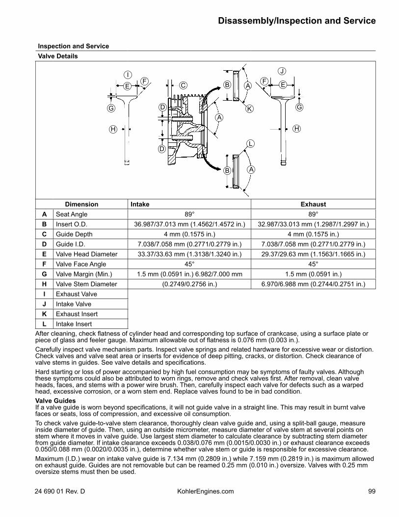
Inspection and ServiceValve Details
A
A
A
B
B
C
D
D
EEF F
GG
HH
I J
K
L
Dimension Intake ExhaustA Seat Angle 89° 89°B Insert O.D. 36.987/37.013 mm (1.4562/1.4572 in.) 32.987/33.013 mm (1.2987/1.2997 in.)C Guide Depth 4 mm (0.1575 in.) 4 mm (0.1575 in.)D Guide I.D. 7.038/7.058 mm (0.2771/0.2779 in.) 7.038/7.058 mm (0.2771/0.2779 in.)E Valve Head Diameter 33.37/33.63 mm (1.3138/1.3240 in.) 29.37/29.63 mm (1.1563/1.1665 in.)F Valve Face Angle 45° 45°G Valve Margin (Min.) 1.5 mm (0.0591 in.) 6.982/7.000 mm 1.5 mm (0.0591 in.)H Valve Stem Diameter (0.2749/0.2756 in.) 6.970/6.988 mm (0.2744/0.2751 in.)I Exhaust ValveJ Intake ValveK Exhaust InsertL Intake Insert
After cleaning, check flatness of cylinder head and corresponding top surface of crankcase, using a surface plate or piece of glass and feeler gauge. Maximum allowable out of flatness is 0.076 mm (0.003 in.).Carefully inspect valve mechanism parts. Inspect valve springs and related hardware for excessive wear or distortion. Check valves and valve seat area or inserts for evidence of deep pitting, cracks, or distortion. Check clearance of valve stems in guides. See valve details and specifications.Hard starting or loss of power accompanied by high fuel consumption may be symptoms of faulty valves. Although these symptoms could also be attributed to worn rings, remove and check valves first. After removal, clean valve heads, faces, and stems with a power wire brush. Then, carefully inspect each valve for defects such as a warped head, excessive corrosion, or a worn stem end. Replace valves found to be in bad condition.Valve GuidesIf a valve guide is worn beyond specifications, it will not guide valve in a straight line. This may result in burnt valve faces or seats, loss of compression, and excessive oil consumption.To check valve guide-to-valve stem clearance, thoroughly clean valve guide and, using a split-ball gauge, measure inside diameter of guide. Then, using an outside micrometer, measure diameter of valve stem at several points on stem where it moves in valve guide. Use largest stem diameter to calculate clearance by subtracting stem diameter from guide diameter. If intake clearance exceeds 0.038/0.076 mm (0.0015/0.0030 in.) or exhaust clearance exceeds 0.050/0.088 mm (0.0020/0.0035 in.), determine whether valve stem or guide is responsible for excessive clearance.Maximum (I.D.) wear on intake valve guide is 7.134 mm (0.2809 in.) while 7.159 mm (0.2819 in.) is maximum allowed on exhaust guide. Guides are not removable but can be reamed 0.25 mm (0.010 in.) oversize. Valves with 0.25 mm oversize stems must then be used.
Disassembly/Inspection and Service
9924 690 01 Rev. D KohlerEngines.com
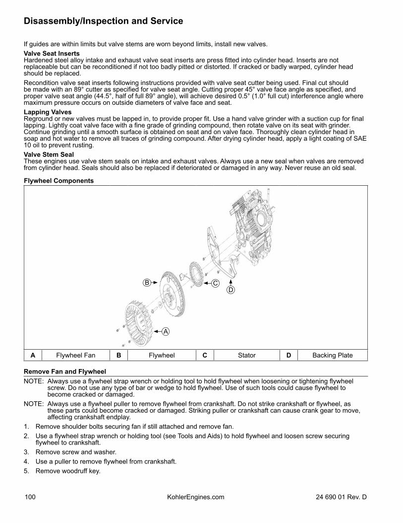
If guides are within limits but valve stems are worn beyond limits, install new valves.Valve Seat InsertsHardened steel alloy intake and exhaust valve seat inserts are press fitted into cylinder head. Inserts are not replaceable but can be reconditioned if not too badly pitted or distorted. If cracked or badly warped, cylinder head should be replaced.Recondition valve seat inserts following instructions provided with valve seat cutter being used. Final cut should be made with an 89° cutter as specified for valve seat angle. Cutting proper 45° valve face angle as specified, and proper valve seat angle (44.5°, half of full 89° angle), will achieve desired 0.5° (1.0° full cut) interference angle where maximum pressure occurs on outside diameters of valve face and seat.Lapping ValvesReground or new valves must be lapped in, to provide proper fit. Use a hand valve grinder with a suction cup for final lapping. Lightly coat valve face with a fine grade of grinding compound, then rotate valve on its seat with grinder. Continue grinding until a smooth surface is obtained on seat and on valve face. Thoroughly clean cylinder head in soap and hot water to remove all traces of grinding compound. After drying cylinder head, apply a light coating of SAE 10 oil to prevent rusting.Valve Stem SealThese engines use valve stem seals on intake and exhaust valves. Always use a new seal when valves are removed from cylinder head. Seals should also be replaced if deteriorated or damaged in any way. Never reuse an old seal.
Flywheel Components
A
BD
C
A Flywheel Fan B Flywheel C Stator D Backing Plate
Remove Fan and FlywheelNOTE: Always use a flywheel strap wrench or holding tool to hold flywheel when loosening or tightening flywheel
screw. Do not use any type of bar or wedge to hold flywheel. Use of such tools could cause flywheel to become cracked or damaged.
NOTE: Always use a flywheel puller to remove flywheel from crankshaft. Do not strike crankshaft or flywheel, as these parts could become cracked or damaged. Striking puller or crankshaft can cause crank gear to move, affecting crankshaft endplay.
1. Remove shoulder bolts securing fan if still attached and remove fan.2. Use a flywheel strap wrench or holding tool (see Tools and Aids) to hold flywheel and loosen screw securing
flywheel to crankshaft.3. Remove screw and washer.4. Use a puller to remove flywheel from crankshaft.5. Remove woodruff key.
Disassembly/Inspection and Service
100 24 690 01 Rev. DKohlerEngines.com
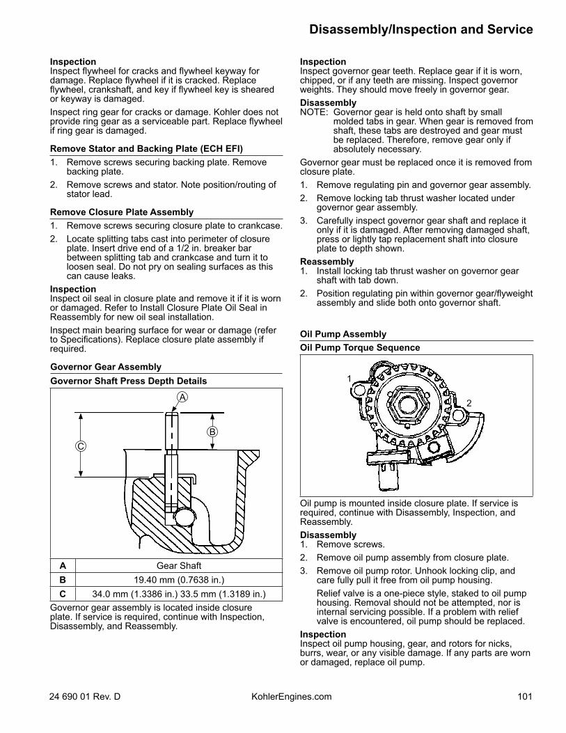
InspectionInspect governor gear teeth. Replace gear if it is worn, chipped, or if any teeth are missing. Inspect governor weights. They should move freely in governor gear.DisassemblyNOTE: Governor gear is held onto shaft by small
molded tabs in gear. When gear is removed from shaft, these tabs are destroyed and gear must be replaced. Therefore, remove gear only if absolutely necessary.
Governor gear must be replaced once it is removed from closure plate.1. Remove regulating pin and governor gear assembly.2. Remove locking tab thrust washer located under
governor gear assembly.3. Carefully inspect governor gear shaft and replace it
only if it is damaged. After removing damaged shaft, press or lightly tap replacement shaft into closure plate to depth shown.
Reassembly1. Install locking tab thrust washer on governor gear
shaft with tab down.2. Position regulating pin within governor gear/flyweight
assembly and slide both onto governor shaft.
Oil Pump AssemblyOil Pump Torque Sequence
1
2
Oil pump is mounted inside closure plate. If service is required, continue with Disassembly, Inspection, and Reassembly.Disassembly1. Remove screws.2. Remove oil pump assembly from closure plate.3. Remove oil pump rotor. Unhook locking clip, and
care fully pull it free from oil pump housing. Relief valve is a one-piece style, staked to oil pump
housing. Removal should not be attempted, nor is internal servicing possible. If a problem with relief valve is encountered, oil pump should be replaced.
InspectionInspect oil pump housing, gear, and rotors for nicks, burrs, wear, or any visible damage. If any parts are worn or damaged, replace oil pump.
InspectionInspect flywheel for cracks and flywheel keyway for damage. Replace flywheel if it is cracked. Replace flywheel, crankshaft, and key if flywheel key is sheared or keyway is damaged.Inspect ring gear for cracks or damage. Kohler does not provide ring gear as a serviceable part. Replace flywheel if ring gear is damaged.
Remove Stator and Backing Plate (ECH EFI)1. Remove screws securing backing plate. Remove
backing plate.2. Remove screws and stator. Note position/routing of
stator lead.
Remove Closure Plate Assembly1. Remove screws securing closure plate to crankcase.2. Locate splitting tabs cast into perimeter of closure
plate. Insert drive end of a 1/2 in. breaker bar between splitting tab and crankcase and turn it to loosen seal. Do not pry on sealing surfaces as this can cause leaks.
InspectionInspect oil seal in closure plate and remove it if it is worn or damaged. Refer to Install Closure Plate Oil Seal in Reassembly for new oil seal installation.Inspect main bearing surface for wear or damage (refer to Specifications). Replace closure plate assembly if required.
Governor Gear AssemblyGovernor Shaft Press Depth Details
CB
A
A Gear ShaftB 19.40 mm (0.7638 in.)C 34.0 mm (1.3386 in.) 33.5 mm (1.3189 in.)
Governor gear assembly is located inside closure plate. If service is required, continue with Inspection, Disassembly, and Reassembly.
Disassembly/Inspection and Service
10124 690 01 Rev. D KohlerEngines.com
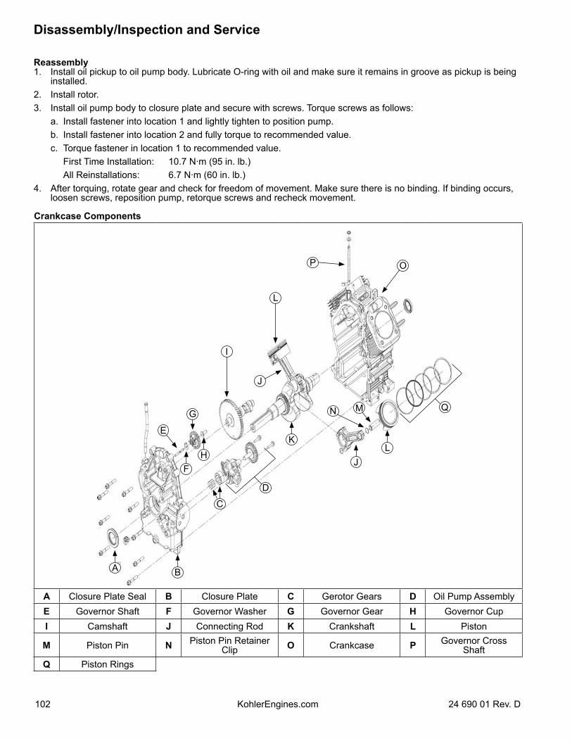
Reassembly1. Install oil pickup to oil pump body. Lubricate O-ring with oil and make sure it remains in groove as pickup is being
installed.2. Install rotor.3. Install oil pump body to closure plate and secure with screws. Torque screws as follows: a. Install fastener into location 1 and lightly tighten to position pump. b. Install fastener into location 2 and fully torque to recommended value. c. Torque fastener in location 1 to recommended value. First Time Installation: 10.7 N·m (95 in. lb.) All Reinstallations: 6.7 N·m (60 in. lb.)4. After torquing, rotate gear and check for freedom of movement. Make sure there is no binding. If binding occurs,
loosen screws, reposition pump, retorque screws and recheck movement.
Crankcase Components
A B
C
HF
K
G
L
J
D
E
J
I
L
MN
P O
Q
A Closure Plate Seal B Closure Plate C Gerotor Gears D Oil Pump AssemblyE Governor Shaft F Governor Washer G Governor Gear H Governor CupI Camshaft J Connecting Rod K Crankshaft L Piston
M Piston Pin N Piston Pin Retainer Clip O Crankcase P Governor Cross
ShaftQ Piston Rings
Disassembly/Inspection and Service
102 24 690 01 Rev. DKohlerEngines.com
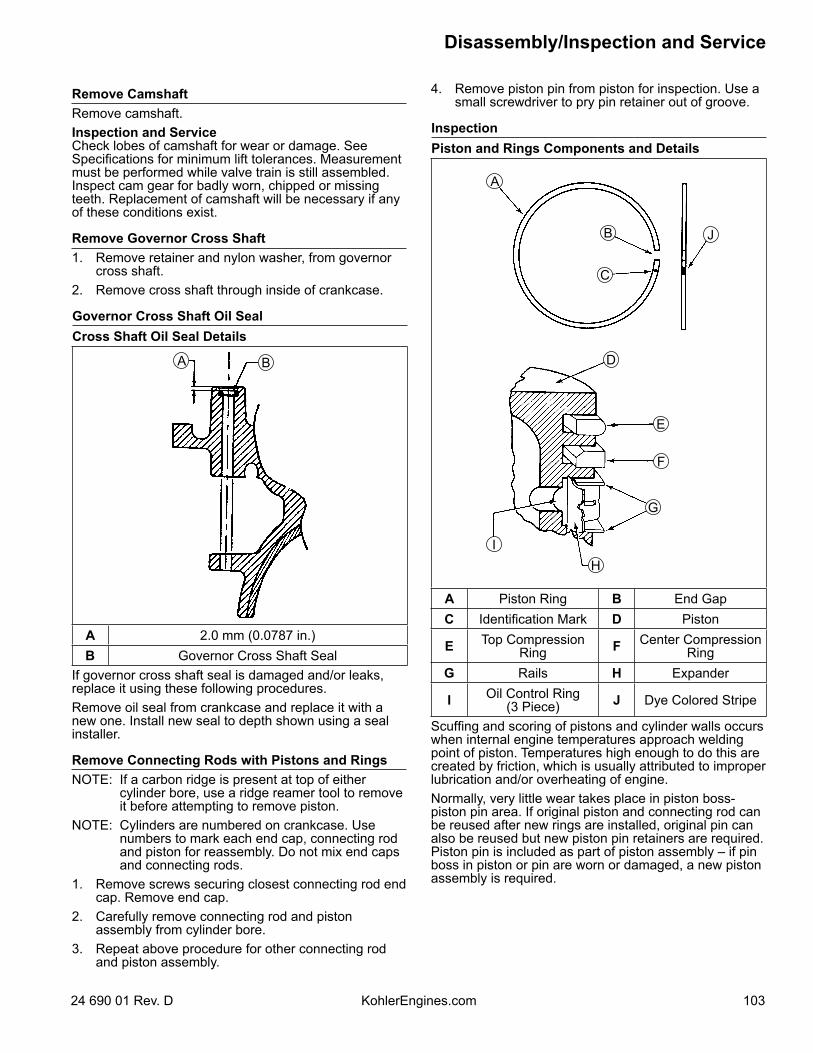
Remove CamshaftRemove camshaft.Inspection and ServiceCheck lobes of camshaft for wear or damage. See Specifications for minimum lift tolerances. Measurement must be performed while valve train is still assembled. Inspect cam gear for badly worn, chipped or missing teeth. Replacement of camshaft will be necessary if any of these conditions exist.
Remove Governor Cross Shaft1. Remove retainer and nylon washer, from governor
cross shaft.2. Remove cross shaft through inside of crankcase.
Governor Cross Shaft Oil SealCross Shaft Oil Seal Details
BA
A 2.0 mm (0.0787 in.)B Governor Cross Shaft Seal
If governor cross shaft seal is damaged and/or leaks, replace it using these following procedures.Remove oil seal from crankcase and replace it with a new one. Install new seal to depth shown using a seal installer.
Remove Connecting Rods with Pistons and RingsNOTE: If a carbon ridge is present at top of either
cylinder bore, use a ridge reamer tool to remove it before attempting to remove piston.
NOTE: Cylinders are numbered on crankcase. Use numbers to mark each end cap, connecting rod and piston for reassembly. Do not mix end caps and connecting rods.
1. Remove screws securing closest connecting rod end cap. Remove end cap.
2. Carefully remove connecting rod and piston assembly from cylinder bore.
3. Repeat above procedure for other connecting rod and piston assembly.
4. Remove piston pin from piston for inspection. Use a small screwdriver to pry pin retainer out of groove.
InspectionPiston and Rings Components and Details
A
B
C
D
E
F
J
G
IH
A Piston Ring B End GapC Identification Mark D Piston
E Top Compression Ring F Center Compression
RingG Rails H Expander
I Oil Control Ring(3 Piece) J Dye Colored Stripe
Scuffing and scoring of pistons and cylinder walls occurs when internal engine temperatures approach welding point of piston. Temperatures high enough to do this are created by friction, which is usually attributed to improper lubrication and/or overheating of engine.Normally, very little wear takes place in piston boss-piston pin area. If original piston and connecting rod can be reused after new rings are installed, original pin can also be reused but new piston pin retainers are required. Piston pin is included as part of piston assembly – if pin boss in piston or pin are worn or damaged, a new piston assembly is required.
Disassembly/Inspection and Service
10324 690 01 Rev. D KohlerEngines.com
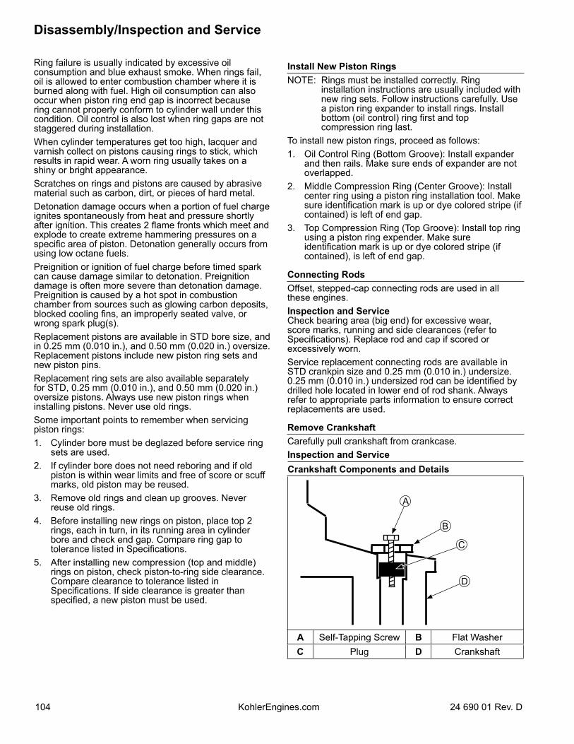
Ring failure is usually indicated by excessive oil consumption and blue exhaust smoke. When rings fail, oil is allowed to enter combustion chamber where it is burned along with fuel. High oil consumption can also occur when piston ring end gap is incorrect because ring cannot properly conform to cylinder wall under this condition. Oil control is also lost when ring gaps are not staggered during installation.When cylinder temperatures get too high, lacquer and varnish collect on pistons causing rings to stick, which results in rapid wear. A worn ring usually takes on a shiny or bright appearance.Scratches on rings and pistons are caused by abrasive material such as carbon, dirt, or pieces of hard metal.Detonation damage occurs when a portion of fuel charge ignites spontaneously from heat and pressure shortly after ignition. This creates 2 flame fronts which meet and explode to create extreme hammering pressures on a specific area of piston. Detonation generally occurs from using low octane fuels.Preignition or ignition of fuel charge before timed spark can cause damage similar to detonation. Preignition damage is often more severe than detonation damage. Preignition is caused by a hot spot in combustion chamber from sources such as glowing carbon deposits, blocked cooling fins, an improperly seated valve, or wrong spark plug(s). Replacement pistons are available in STD bore size, and in 0.25 mm (0.010 in.), and 0.50 mm (0.020 in.) oversize. Replacement pistons include new piston ring sets and new piston pins.Replacement ring sets are also available separately for STD, 0.25 mm (0.010 in.), and 0.50 mm (0.020 in.) oversize pistons. Always use new piston rings when installing pistons. Never use old rings.Some important points to remember when servicing piston rings:1. Cylinder bore must be deglazed before service ring
sets are used.2. If cylinder bore does not need reboring and if old
piston is within wear limits and free of score or scuff marks, old piston may be reused.
3. Remove old rings and clean up grooves. Never reuse old rings.
4. Before installing new rings on piston, place top 2 rings, each in turn, in its running area in cylinder bore and check end gap. Compare ring gap to tolerance listed in Specifications.
5. After installing new compression (top and middle) rings on piston, check piston-to-ring side clearance. Compare clearance to tolerance listed in Specifications. If side clearance is greater than specified, a new piston must be used.
Install New Piston RingsNOTE: Rings must be installed correctly. Ring
installation instructions are usually included with new ring sets. Follow instructions carefully. Use a piston ring expander to install rings. Install bottom (oil control) ring first and top compression ring last.
To install new piston rings, proceed as follows:1. Oil Control Ring (Bottom Groove): Install expander
and then rails. Make sure ends of expander are not overlapped.
2. Middle Compression Ring (Center Groove): Install center ring using a piston ring installation tool. Make sure identification mark is up or dye colored stripe (if contained) is left of end gap.
3. Top Compression Ring (Top Groove): Install top ring using a piston ring expender. Make sure identification mark is up or dye colored stripe (if contained), is left of end gap.
Connecting RodsOffset, stepped-cap connecting rods are used in all these engines.Inspection and ServiceCheck bearing area (big end) for excessive wear, score marks, running and side clearances (refer to Specifications). Replace rod and cap if scored or excessively worn.Service replacement connecting rods are available in STD crankpin size and 0.25 mm (0.010 in.) undersize. 0.25 mm (0.010 in.) undersized rod can be identified by drilled hole located in lower end of rod shank. Always refer to appropriate parts information to ensure correct replacements are used.
Remove CrankshaftCarefully pull crankshaft from crankcase.Inspection and ServiceCrankshaft Components and Details
A
B
C
D
A Self-Tapping Screw B Flat WasherC Plug D Crankshaft
Disassembly/Inspection and Service
104 24 690 01 Rev. DKohlerEngines.com
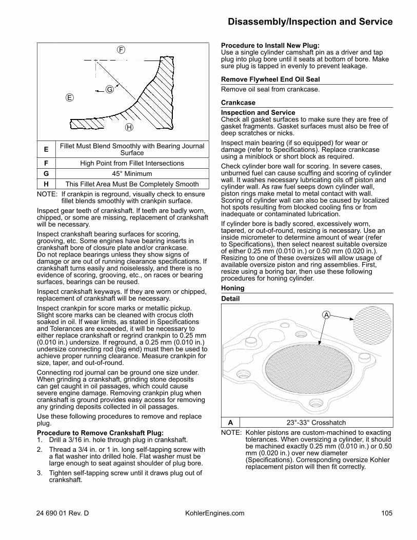
EG
F
H
E Fillet Must Blend Smoothly with Bearing JournalSurface
F High Point from Fillet IntersectionsG 45° MinimumH This Fillet Area Must Be Completely Smooth
NOTE: If crankpin is reground, visually check to ensure fillet blends smoothly with crankpin surface.
Inspect gear teeth of crankshaft. If teeth are badly worn, chipped, or some are missing, replacement of crankshaft will be necessary.Inspect crankshaft bearing surfaces for scoring, grooving, etc. Some engines have bearing inserts in crankshaft bore of closure plate and/or crankcase. Do not replace bearings unless they show signs of damage or are out of running clearance specifications. If crankshaft turns easily and noiselessly, and there is no evidence of scoring, grooving, etc., on races or bearing surfaces, bearings can be reused.Inspect crankshaft keyways. If they are worn or chipped, replacement of crankshaft will be necessary.Inspect crankpin for score marks or metallic pickup. Slight score marks can be cleaned with crocus cloth soaked in oil. If wear limits, as stated in Specifications and Tolerances are exceeded, it will be necessary to either replace crankshaft or regrind crankpin to 0.25 mm (0.010 in.) undersize. If reground, a 0.25 mm (0.010 in.) undersize connecting rod (big end) must then be used to achieve proper running clearance. Measure crankpin for size, taper, and out-of-round.Connecting rod journal can be ground one size under. When grinding a crankshaft, grinding stone deposits can get caught in oil passages, which could cause severe engine damage. Removing crankpin plug when crankshaft is ground provides easy access for removing any grinding deposits collected in oil passages.Use these following procedures to remove and replace plug.Procedure to Remove Crankshaft Plug:1. Drill a 3/16 in. hole through plug in crankshaft.2. Thread a 3/4 in. or 1 in. long self-tapping screw with
a flat washer into drilled hole. Flat washer must be large enough to seat against shoulder of plug bore.
3. Tighten self-tapping screw until it draws plug out of crankshaft.
Procedure to Install New Plug:Use a single cylinder camshaft pin as a driver and tap plug into plug bore until it seats at bottom of bore. Make sure plug is tapped in evenly to prevent leakage.
Remove Flywheel End Oil SealRemove oil seal from crankcase.
CrankcaseInspection and ServiceCheck all gasket surfaces to make sure they are free of gasket fragments. Gasket surfaces must also be free of deep scratches or nicks.Inspect main bearing (if so equipped) for wear or damage (refer to Specifications). Replace crankcase using a miniblock or short block as required.Check cylinder bore wall for scoring. In severe cases, unburned fuel can cause scuffing and scoring of cylinder wall. It washes necessary lubricating oils off piston and cylinder wall. As raw fuel seeps down cylinder wall, piston rings make metal to metal contact with wall. Scoring of cylinder wall can also be caused by localized hot spots resulting from blocked cooling fins or from inadequate or contaminated lubrication.If cylinder bore is badly scored, excessively worn, tapered, or out-of-round, resizing is necessary. Use an inside micrometer to determine amount of wear (refer to Specifications), then select nearest suitable oversize of either 0.25 mm (0.010 in.) or 0.50 mm (0.020 in.). Resizing to one of these oversizes will allow usage of available oversize piston and ring assemblies. First, resize using a boring bar, then use these following procedures for honing cylinder.HoningDetail
A
A 23°-33° CrosshatchNOTE: Kohler pistons are custom-machined to exacting
tolerances. When oversizing a cylinder, it should be machined exactly 0.25 mm (0.010 in.) or 0.50 mm (0.020 in.) over new diameter (Specifications). Corresponding oversize Kohler replacement piston will then fit correctly.
Disassembly/Inspection and Service
10524 690 01 Rev. D KohlerEngines.com
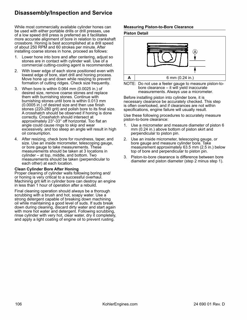
While most commercially available cylinder hones can be used with either portable drills or drill presses, use of a low speed drill press is preferred as it facilitates more accurate alignment of bore in relation to crankshaft crossbore. Honing is best accomplished at a drill speed of about 250 RPM and 60 strokes per minute. After installing coarse stones in hone, proceed as follows:1. Lower hone into bore and after centering, adjust so
stones are in contact with cylinder wall. Use of a commercial cutting-cooling agent is recommended.
2. With lower edge of each stone positioned even with lowest edge of bore, start drill and honing process. Move hone up and down while resizing to prevent formation of cutting ridges. Check size frequently.
3. When bore is within 0.064 mm (0.0025 in.) of desired size, remove coarse stones and replace them with burnishing stones. Continue with burnishing stones until bore is within 0.013 mm (0.0005 in.) of desired size and then use finish stones (220-280 grit) and polish bore to its final size. A crosshatch should be observed if honing is done correctly. Crosshatch should intersect at approximately 23°-33° off horizontal. Too flat an angle could cause rings to skip and wear excessively, and too steep an angle will result in high oil consumption.
4. After resizing, check bore for roundness, taper, and size. Use an inside micrometer, telescoping gauge, or bore gauge to take measurements. These measurements should be taken at 3 locations in cylinder – at top, middle, and bottom. Two measurements should be taken (perpendicular to each other) at each location.
Clean Cylinder Bore After HoningProper cleaning of cylinder walls following boring and/or honing is very critical to a successful overhaul. Machining grit left in cylinder bore can destroy an engine in less than 1 hour of operation after a rebuild.Final cleaning operation should always be a thorough scrubbing with a brush and hot, soapy water. Use a strong detergent capable of breaking down machining oil while maintaining a good level of suds. If suds break down during cleaning, discard dirty water and start again with more hot water and detergent. Following scrubbing, rinse cylinder with very hot, clear water, dry it completely, and apply a light coating of engine oil to prevent rusting.
Measuring Piston-to-Bore ClearancePiston Detail
A
A 6 mm (0.24 in.)NOTE: Do not use a feeler gauge to measure piston-to-
bore clearance – it will yield inaccurate measurements. Always use a micrometer.
Before installing piston into cylinder bore, it is necessary clearance be accurately checked. This step is often overlooked, and if clearances are not within specifications, engine failure will usually result.Use these following procedures to accurately measure piston-to-bore clearance:1. Use a micrometer and measure diameter of piston 6
mm (0.24 in.) above bottom of piston skirt and perpendicular to piston pin.
2. Use an inside micrometer, telescoping gauge, or bore gauge and measure cylinder bore. Take measurement approximately 63.5 mm (2.5 in.) below top of bore and perpendicular to piston pin.
3. Piston-to-bore clearance is difference between bore diameter and piston diameter (step 2 minus step 1).
Disassembly/Inspection and Service
106 24 690 01 Rev. DKohlerEngines.com
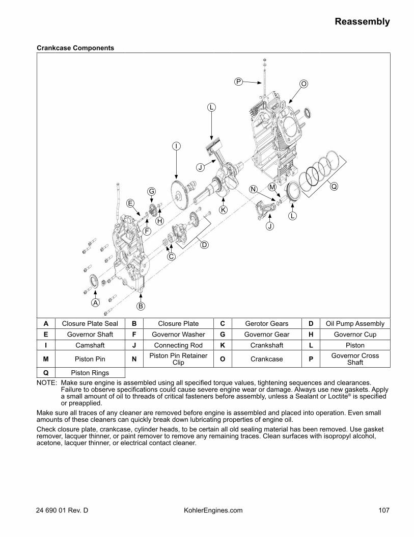
Crankcase Components
A B
C
HF
K
G
L
J
D
E
J
I
L
MN
P O
Q
A Closure Plate Seal B Closure Plate C Gerotor Gears D Oil Pump AssemblyE Governor Shaft F Governor Washer G Governor Gear H Governor CupI Camshaft J Connecting Rod K Crankshaft L Piston
M Piston Pin N Piston Pin Retainer Clip O Crankcase P Governor Cross
ShaftQ Piston Rings
NOTE: Make sure engine is assembled using all specified torque values, tightening sequences and clearances. Failure to observe specifications could cause severe engine wear or damage. Always use new gaskets. Apply a small amount of oil to threads of critical fasteners before assembly, unless a Sealant or Loctite® is specified or preapplied.
Make sure all traces of any cleaner are removed before engine is assembled and placed into operation. Even small amounts of these cleaners can quickly break down lubricating properties of engine oil.Check closure plate, crankcase, cylinder heads, to be certain all old sealing material has been removed. Use gasket remover, lacquer thinner, or paint remover to remove any remaining traces. Clean surfaces with isopropyl alcohol, acetone, lacquer thinner, or electrical contact cleaner.
Reassembly
10724 690 01 Rev. D KohlerEngines.com
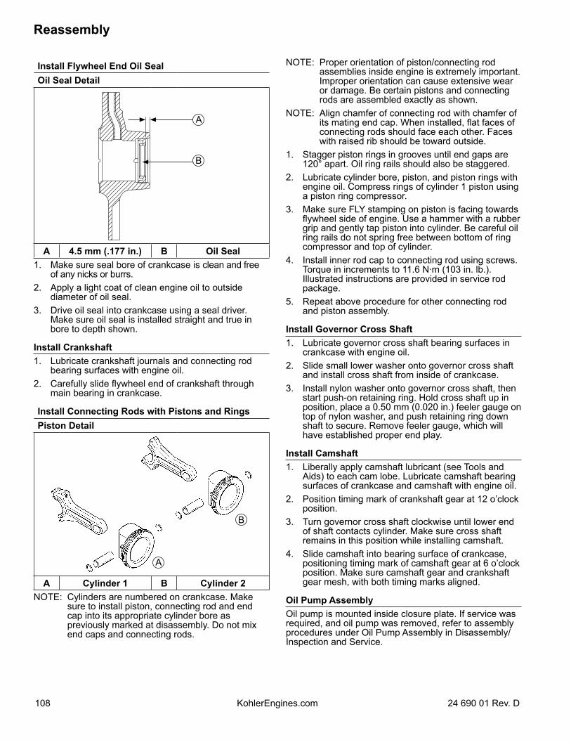
Install Flywheel End Oil SealOil Seal Detail
B
A
A 4.5 mm (.177 in.) B Oil Seal1. Make sure seal bore of crankcase is clean and free
of any nicks or burrs.2. Apply a light coat of clean engine oil to outside
diameter of oil seal.3. Drive oil seal into crankcase using a seal driver.
Make sure oil seal is installed straight and true in bore to depth shown.
Install Crankshaft1. Lubricate crankshaft journals and connecting rod
bearing surfaces with engine oil.2. Carefully slide flywheel end of crankshaft through
main bearing in crankcase.
Install Connecting Rods with Pistons and RingsPiston Detail
A
B
A Cylinder 1 B Cylinder 2NOTE: Cylinders are numbered on crankcase. Make
sure to install piston, connecting rod and end cap into its appropriate cylinder bore as previously marked at disassembly. Do not mix end caps and connecting rods.
NOTE: Proper orientation of piston/connecting rod assemblies inside engine is extremely important. Improper orientation can cause extensive wear or damage. Be certain pistons and connecting rods are assembled exactly as shown.
NOTE: Align chamfer of connecting rod with chamfer of its mating end cap. When installed, flat faces of connecting rods should face each other. Faces with raised rib should be toward outside.
1. Stagger piston rings in grooves until end gaps are 120° apart. Oil ring rails should also be staggered.
2. Lubricate cylinder bore, piston, and piston rings with engine oil. Compress rings of cylinder 1 piston using a piston ring compressor.
3. Make sure FLY stamping on piston is facing towards flywheel side of engine. Use a hammer with a rubber grip and gently tap piston into cylinder. Be careful oil ring rails do not spring free between bottom of ring compressor and top of cylinder.
4. Install inner rod cap to connecting rod using screws. Torque in increments to 11.6 N·m (103 in. lb.). Illustrated instructions are provided in service rod package.
5. Repeat above procedure for other connecting rod and piston assembly.
Install Governor Cross Shaft1. Lubricate governor cross shaft bearing surfaces in
crankcase with engine oil.2. Slide small lower washer onto governor cross shaft
and install cross shaft from inside of crankcase.3. Install nylon washer onto governor cross shaft, then
start push-on retaining ring. Hold cross shaft up in position, place a 0.50 mm (0.020 in.) feeler gauge on top of nylon washer, and push retaining ring down shaft to secure. Remove feeler gauge, which will have established proper end play.
Install Camshaft1. Liberally apply camshaft lubricant (see Tools and
Aids) to each cam lobe. Lubricate camshaft bearing surfaces of crankcase and camshaft with engine oil.
2. Position timing mark of crankshaft gear at 12 o’clock position.
3. Turn governor cross shaft clockwise until lower end of shaft contacts cylinder. Make sure cross shaft remains in this position while installing camshaft.
4. Slide camshaft into bearing surface of crankcase, positioning timing mark of camshaft gear at 6 o’clock position. Make sure camshaft gear and crankshaft gear mesh, with both timing marks aligned.
Oil Pump AssemblyOil pump is mounted inside closure plate. If service was required, and oil pump was removed, refer to assembly procedures under Oil Pump Assembly in Disassembly/Inspection and Service.
Reassembly
108 24 690 01 Rev. DKohlerEngines.com
Governor Gear AssemblyGovernor gear assembly is located inside closure plate. If service was required, and governor was removed, refer to assembly procedures under Governor Gear Assembly in Disassembly/Inspection and Service.
Thrust Bearing, Washer and Shim
A
B
C
D
E
A Thrust Shim B Thrust Washer
C Needle Thrust Bearing D Bearing Race
E Closure PlateSome specifications use a needle type thrust bearing, thrust washer and shim spacer to control end play of crankshaft. If these items are noted during disassembly, make sure they are reinstalled in sequence shown. A different procedure will have to be followed to check and adjust crankshaft end play on these models.Race for thrust bearing presses loosely into closure plate. If it is not already installed, push it into crankshaft bore inside closure plate. Pack thrust bearing with heavy grease and stick bearing into race. Wipe some grease on face of thrust washer and stick it onto thrust bearing. Wipe some grease on face of original shim spacer and stick it onto thrust washer.Install closure plate onto crankcase without applying RTV sealant and secure it with only 2 or 3 fasteners at this time. Use a dial indicator to check crankshaft end play. End play should be 0.070/0.270 mm (0.0028/0.0100 in.). Shim spacers are available in 3 color coded thicknesses if adjustment is needed.
Clearance Specifications-Crankshaft End Play ShimsGreen 0.8366-0.9127 mm
(0.8750 mm/0.034 in. Nominal)Yellow 1.0652-1.1414 mm
(1.1033 mm/0.043 in. Nominal)Red 1.2938-1.3700 mm
(1.3319 mm/0.052 in. Nominal)Remove closure plate. If end play requires adjustment, remove original spacer and install appropriate size shim spacer in its place. Then follow procedure under Install Closure Plate Assembly.
Install Closure Plate Oil SealOil Seal Details
A
BC
A Oil Seal B 8.0 mm (0.314 in.)C Seal Depth
1. Check to make sure there are no nicks or burrs in crankshaft bore of closure plate.
2. Apply a light coat of engine oil to outside diameter of oil seal.
3. Drive oil seal into closure plate using a seal driver. Make sure oil seal is installed straight and true in bore to depth shown.
Reassembly
10924 690 01 Rev. D KohlerEngines.com
Install Closure Plate Assembly
A
A RTV Must Be All Around O-ring Groove.RTV sealant is used as a gasket between closure plate and crankcase. Refer to Tools and Aids for a listing of approved sealants. Always use fresh sealant. Using outdated sealant can result in leakage.1. Be sure sealing surfaces have been cleaned and
prepared as described at beginning of Disassembly/Inspection and Service.
2. Check to make sure there are no nicks or burrs on sealing surfaces of closure plate or crankcase.
3. Apply a 1.5 mm (1/16 in.) bead of sealant to sealing surface of closure plate. Verify O-ring is present. See sealant pattern.
4. Make sure end of governor cross shaft is lying against bottom of cylinder 1 inside crankcase.
5. Install closure plate to crankcase. Carefully seat camshaft and crankshaft into their mating bearings. Rotate crankshaft slightly to help engage oil pump and governor gear meshes.
6. Install screws securing closure plate to crankcase. Torque fasteners in sequence shown to 25.6 N·m (227 in. lb.). One mounting screws has a thread sealant patch. This screw is typically installed in #10 hole shown. Reapply pipe sealant with Teflon® (Loctite® 592™ PST® Thread Sealant or equivalent).
Closure Plate Fastener Torque Sequence
10
6
2
9
7
31
8
4
5
Install Stator and Backing Plate1. Apply pipe sealant with Teflon® (Loctite® 592™ PST®
Thread Sealant or equivalent) to stator mounting holes.
2. Position stator aligning mounting holes so leads are at bottom, towards crankcase.
3. Install and torque screws to 6.2 N·m (55 in. lb.) into new holes or 4.0 N·m (35 in. lb.) into used holes.
4. Route stator leads in crankcase channel, then install backing plate. Secure using screws. Torque screws to 10.7 N·m (95 in. lb.) into new holes or 7.3 N·m (65 in. lb.) into used holes.
Reassembly
110 24 690 01 Rev. DKohlerEngines.com
Install Flywheel
CAUTIONDamaging Crankshaft and Flywheel Can cause personal injury.
Using improper procedures can lead to broken fragments. Broken fragments could be thrown from engine. Always observe and use precautions and procedures when installing flywheel.
Flywheel Components
B
A
C
D
A Flywheel Fan B Flywheel
C Stator D Backing PlateNOTE: Before installing flywheel make sure crankshaft
taper and flywheel hub are clean, dry, and completely free of any lubricants. Presence of lubricants can cause flywheel to be over stressed and damaged when screw is torqued to specifications.
NOTE: Make sure flywheel key is installed properly in keyway. Flywheel can become cracked or damaged if key is not properly installed.
1. Install woodruff key into keyway of crankshaft. Make sure key is properly seated and parallel with shaft taper.
2. Install flywheel onto crankshaft being careful not to shift woodruff key.
3. Install screw and washer.4. Use a flywheel strap wrench or holding tool to hold
flywheel. Torque screw securing flywheel to crankshaft to 71.6 N·m (52.8 ft. lb.).
Install FanNOTE: Position locating tabs on back of fan in locating
holes of flywheel.1. Install fan onto flywheel using screws (engines with
plastic grass screen). Engines with a metal grass screen will leave fan loosely assembled.
2. Torque screws to 9.9 N·m (88 in. lb.).
Install Hydraulic Lifters NOTE: Hydraulic lifters should always be installed in
same position as before disassembly. Exhaust lifters are located on output shaft side of engine while intake lifters are located on fan side of engine. Cylinder numbers are embossed on top of crankcase and each cylinder head.
1. See Servicing Hydraulic Lifters in Disassembly/Inspection and Service.
2. Apply camshaft lubricant to bottom surface of each lifter. Lubricate hydraulic lifters and lifter bores in crankcase with engine oil.
3. Note mark or tag identifying hydraulic lifters as either intake or exhaust and cylinder 1 or cylinder 2. Install hydraulic lifters into their appropriate location in crankcase. Do not use a magnet.
4. If breather reeds and stops were removed from crankcase, reinstall them at this time and secure with screw. Torque screw to 4.0 N·m (35 in. lb.).
Reassembly
11124 690 01 Rev. D KohlerEngines.com
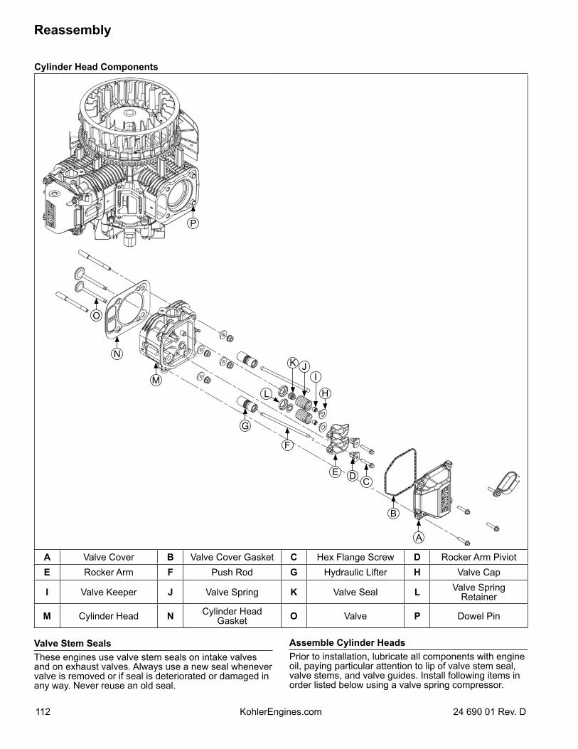
Cylinder Head Components
A
B
CDE
F
H
IJK
L
G
M
O
N
P
A Valve Cover B Valve Cover Gasket C Hex Flange Screw D Rocker Arm PiviotE Rocker Arm F Push Rod G Hydraulic Lifter H Valve Cap
I Valve Keeper J Valve Spring K Valve Seal L Valve Spring Retainer
M Cylinder Head N Cylinder Head Gasket O Valve P Dowel Pin
Valve Stem SealsThese engines use valve stem seals on intake valves and on exhaust valves. Always use a new seal whenever valve is removed or if seal is deteriorated or damaged in any way. Never reuse an old seal.
Assemble Cylinder HeadsPrior to installation, lubricate all components with engine oil, paying particular attention to lip of valve stem seal, valve stems, and valve guides. Install following items in order listed below using a valve spring compressor.
Reassembly
112 24 690 01 Rev. DKohlerEngines.com
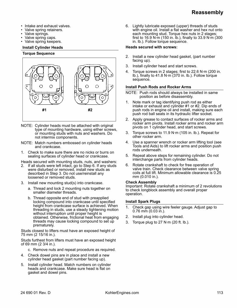
• Intake and exhaust valves.• Valve spring retainers.• Valve springs.• Valve spring caps.• Valve spring keepers.Install Cylinder HeadsTorque Sequence
#1 #2
NOTE: Cylinder heads must be attached with original type of mounting hardware, using either screws, or mounting studs with nuts and washers. Do not intermix components.
NOTE: Match numbers embossed on cylinder heads and crankcase.
1. Check to make sure there are no nicks or burrs on sealing surfaces of cylinder head or crankcase.
Heads secured with mounting studs, nuts, and washers:2. If all studs were left intact, go to Step 6. If any studs
were disturbed or removed, install new studs as described in Step 3. Do not use/reinstall any loosened or removed studs.
3. Install new mounting stud(s) into crankcase. a. Thread and lock 2 mounting nuts together on
smaller diameter threads. b. Thread opposite end of stud with preapplied
locking compound into crankcase until specified height from crankcase surface is achieved. When threading in studs, use a steady tightening motion without interruption until proper height is obtained. Otherwise, frictional heat from engaging threads may cause locking compound to set up prematurely.
Studs closest to lifters must have an exposed height of 75 mm (2 15/16 in.).Studs furthest from lifters must have an exposed height of 69 mm (2 3/4 in.). c. Remove nuts and repeat procedure as required.4. Check dowel pins are in place and install a new
cylinder head gasket (part number facing up).5. Install cylinder head. Match numbers on cylinder
heads and crankcase. Make sure head is flat on gasket and dowel pins.
6. Lightly lubricate exposed (upper) threads of studs with engine oil. Install a flat washer and hex nut onto each mounting stud. Torque hex nuts in 2 stages; first to 16.9 N·m (150 in. lb.), finally to 33.9 N·m (300 in. lb.). Follow torque sequence.
Heads secured with screws:
2. Install a new cylinder head gasket, (part number facing up).
3. Install cylinder head and start screws.4. Torque screws in 2 stages; first to 22.6 N·m (200 in.
lb.), finally to 41.8 N·m (370 in. lb.). Follow torque sequence.
Install Push Rods and Rocker ArmsNOTE: Push rods should always be installed in same
position as before disassembly.1. Note mark or tag identifying push rod as either
intake or exhaust and cylinder #1 or #2. Dip ends of push rods in engine oil and install, making sure each push rod ball seats in its hydraulic lifter socket.
2. Apply grease to contact surfaces of rocker arms and rocker arm pivots. Install rocker arms and rocker arm pivots on 1 cylinder head, and start screws.
3. Torque screws to 11.9 N·m (105 in. lb.). Repeat for other rocker arm.
4. Use a spanner wrench or rocker arm lifting tool (see Tools and Aids) to lift rocker arms and position push rods underneath.
5. Repeat above steps for remaining cylinder. Do not interchange parts from cylinder heads.
6. Rotate crankshaft to check for free operation of valve train. Check clearance between valve spring coils at full lift. Minimum allowable clearance is 0.25 mm (0.010 in.).
Check AssemblyImportant: Rotate crankshaft a minimum of 2 revolutions to check longblock assembly and overall proper operation.
Install Spark Plugs1. Check gap using wire feeler gauge. Adjust gap to
0.76 mm (0.03 in.).2. Install plug into cylinder head.3. Torque plug to 27 N·m (20 ft. lb.).
Reassembly
11324 690 01 Rev. D KohlerEngines.com
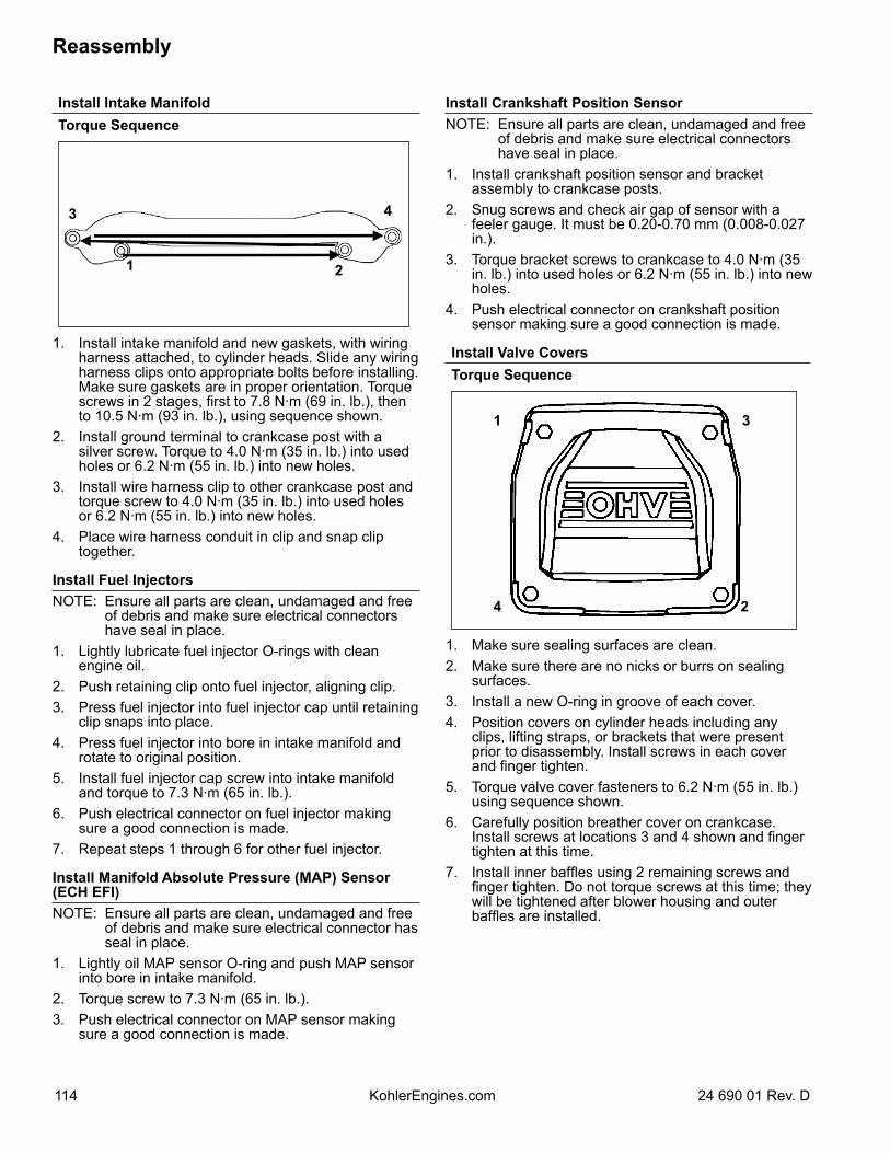
Install Crankshaft Position SensorNOTE: Ensure all parts are clean, undamaged and free
of debris and make sure electrical connectors have seal in place.
1. Install crankshaft position sensor and bracket assembly to crankcase posts.
2. Snug screws and check air gap of sensor with a feeler gauge. It must be 0.20-0.70 mm (0.008-0.027 in.).
3. Torque bracket screws to crankcase to 4.0 N·m (35 in. lb.) into used holes or 6.2 N·m (55 in. lb.) into new holes.
4. Push electrical connector on crankshaft position sensor making sure a good connection is made.
Install Valve CoversTorque Sequence
1
2
3
4
1. Make sure sealing surfaces are clean.2. Make sure there are no nicks or burrs on sealing
surfaces.3. Install a new O-ring in groove of each cover.4. Position covers on cylinder heads including any
clips, lifting straps, or brackets that were present prior to disassembly. Install screws in each cover and finger tighten.
5. Torque valve cover fasteners to 6.2 N·m (55 in. lb.) using sequence shown.
6. Carefully position breather cover on crankcase. Install screws at locations 3 and 4 shown and finger tighten at this time.
7. Install inner baffles using 2 remaining screws and finger tighten. Do not torque screws at this time; they will be tightened after blower housing and outer baffles are installed.
Install Intake ManifoldTorque Sequence
1 2
3 4
1. Install intake manifold and new gaskets, with wiring harness attached, to cylinder heads. Slide any wiring harness clips onto appropriate bolts before installing. Make sure gaskets are in proper orientation. Torque screws in 2 stages, first to 7.8 N·m (69 in. lb.), then to 10.5 N·m (93 in. lb.), using sequence shown.
2. Install ground terminal to crankcase post with a silver screw. Torque to 4.0 N·m (35 in. lb.) into used holes or 6.2 N·m (55 in. lb.) into new holes.
3. Install wire harness clip to other crankcase post and torque screw to 4.0 N·m (35 in. lb.) into used holes or 6.2 N·m (55 in. lb.) into new holes.
4. Place wire harness conduit in clip and snap clip together.
Install Fuel InjectorsNOTE: Ensure all parts are clean, undamaged and free
of debris and make sure electrical connectors have seal in place.
1. Lightly lubricate fuel injector O-rings with clean engine oil.
2. Push retaining clip onto fuel injector, aligning clip.3. Press fuel injector into fuel injector cap until retaining
clip snaps into place.4. Press fuel injector into bore in intake manifold and
rotate to original position.5. Install fuel injector cap screw into intake manifold
and torque to 7.3 N·m (65 in. lb.).6. Push electrical connector on fuel injector making
sure a good connection is made.7. Repeat steps 1 through 6 for other fuel injector.
Install Manifold Absolute Pressure (MAP) Sensor (ECH EFI)NOTE: Ensure all parts are clean, undamaged and free
of debris and make sure electrical connector has seal in place.
1. Lightly oil MAP sensor O-ring and push MAP sensor into bore in intake manifold.
2. Torque screw to 7.3 N·m (65 in. lb.).3. Push electrical connector on MAP sensor making
sure a good connection is made.
Reassembly
114 24 690 01 Rev. DKohlerEngines.com
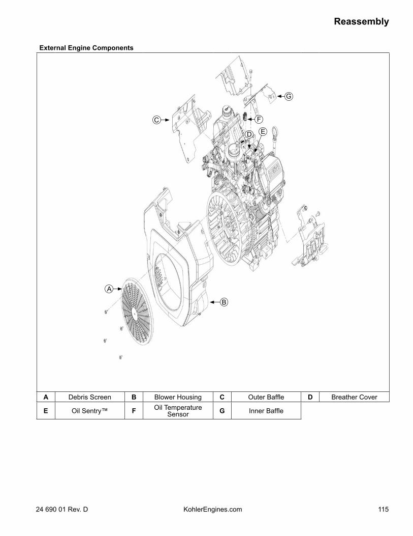
External Engine Components
A
C
D
G
B
F
E
A Debris Screen B Blower Housing C Outer Baffle D Breather Cover
E Oil Sentry™ F Oil Temperature Sensor G Inner Baffle
Reassembly
11524 690 01 Rev. D KohlerEngines.com
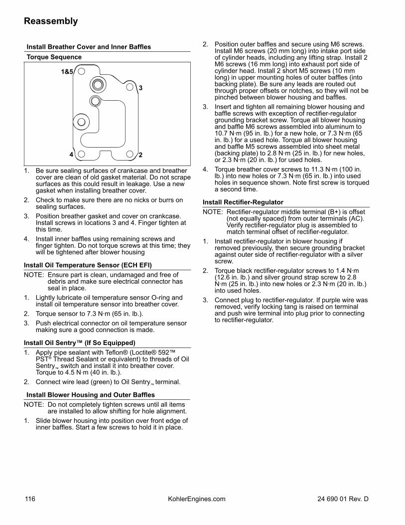
2. Position outer baffles and secure using M6 screws. Install M6 screws (20 mm long) into intake port side of cylinder heads, including any lifting strap. Install 2 M6 screws (16 mm long) into exhaust port side of cylinder head. Install 2 short M5 screws (10 mm long) in upper mounting holes of outer baffles (into backing plate). Be sure any leads are routed out through proper offsets or notches, so they will not be pinched between blower housing and baffles.
3. Insert and tighten all remaining blower housing and baffle screws with exception of rectifier-regulator grounding bracket screw. Torque all blower housing and baffle M6 screws assembled into aluminum to 10.7 N·m (95 in. lb.) for a new hole, or 7.3 N·m (65 in. lb.) for a used hole. Torque all blower housing and baffle M5 screws assembled into sheet metal (backing plate) to 2.8 N·m (25 in. lb.) for new holes, or 2.3 N·m (20 in. lb.) for used holes.
4. Torque breather cover screws to 11.3 N·m (100 in. lb.) into new holes or 7.3 N·m (65 in. lb.) into used holes in sequence shown. Note first screw is torqued a second time.
Install Rectifier-RegulatorNOTE: Rectifier-regulator middle terminal (B+) is offset
(not equally spaced) from outer terminals (AC). Verify rectifier-regulator plug is assembled to match terminal offset of rectifier-regulator.
1. Install rectifier-regulator in blower housing if removed previously, then secure grounding bracket against outer side of rectifier-regulator with a silver screw.
2. Torque black rectifier-regulator screws to 1.4 N·m (12.6 in. lb.) and silver ground strap screw to 2.8 N·m (25 in. lb.) into new holes or 2.3 N·m (20 in. lb.) into used holes.
3. Connect plug to rectifier-regulator. If purple wire was removed, verify locking tang is raised on terminal and push wire terminal into plug prior to connecting to rectifier-regulator.
Install Breather Cover and Inner BafflesTorque Sequence
1&5
2
3
4
1. Be sure sealing surfaces of crankcase and breather cover are clean of old gasket material. Do not scrape surfaces as this could result in leakage. Use a new gasket when installing breather cover.
2. Check to make sure there are no nicks or burrs on sealing surfaces.
3. Position breather gasket and cover on crankcase. Install screws in locations 3 and 4. Finger tighten at this time.
4. Install inner baffles using remaining screws and finger tighten. Do not torque screws at this time; they will be tightened after blower housing
Install Oil Temperature Sensor (ECH EFI)NOTE: Ensure part is clean, undamaged and free of
debris and make sure electrical connector has seal in place.
1. Lightly lubricate oil temperature sensor O-ring and install oil temperature sensor into breather cover.
2. Torque sensor to 7.3 N·m (65 in. lb.).3. Push electrical connector on oil temperature sensor
making sure a good connection is made.
Install Oil Sentry™ (If So Equipped)1. Apply pipe sealant with Teflon® (Loctite® 592™
PST® Thread Sealant or equivalent) to threads of Oil Sentry™ switch and install it into breather cover. Torque to 4.5 N·m (40 in. lb.).
2. Connect wire lead (green) to Oil Sentry™ terminal.
Install Blower Housing and Outer BafflesNOTE: Do not completely tighten screws until all items
are installed to allow shifting for hole alignment.1. Slide blower housing into position over front edge of
inner baffles. Start a few screws to hold it in place.
Reassembly
116 24 690 01 Rev. DKohlerEngines.com
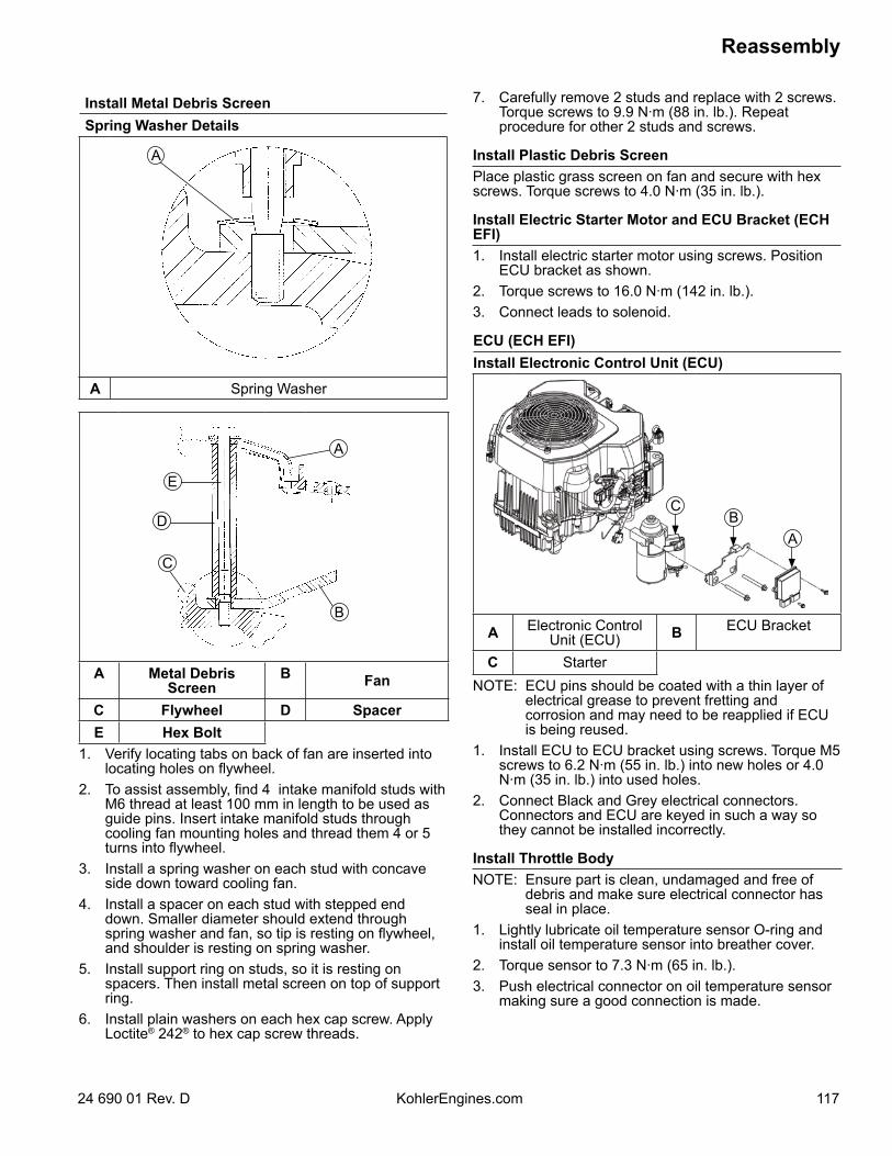
Install Metal Debris ScreenSpring Washer Details
A
A Spring Washer
A
B
C
D
E
A Metal Debris Screen
B Fan
C Flywheel D SpacerE Hex Bolt
1. Verify locating tabs on back of fan are inserted into locating holes on flywheel.
2. To assist assembly, find 4 intake manifold studs with M6 thread at least 100 mm in length to be used as guide pins. Insert intake manifold studs through cooling fan mounting holes and thread them 4 or 5 turns into flywheel.
3. Install a spring washer on each stud with concave side down toward cooling fan.
4. Install a spacer on each stud with stepped end down. Smaller diameter should extend through spring washer and fan, so tip is resting on flywheel, and shoulder is resting on spring washer.
5. Install support ring on studs, so it is resting on spacers. Then install metal screen on top of support ring.
6. Install plain washers on each hex cap screw. Apply Loctite® 242® to hex cap screw threads.
7. Carefully remove 2 studs and replace with 2 screws. Torque screws to 9.9 N·m (88 in. lb.). Repeat procedure for other 2 studs and screws.
Install Plastic Debris ScreenPlace plastic grass screen on fan and secure with hex screws. Torque screws to 4.0 N·m (35 in. lb.).
Install Electric Starter Motor and ECU Bracket (ECH EFI)1. Install electric starter motor using screws. Position
ECU bracket as shown.2. Torque screws to 16.0 N·m (142 in. lb.).3. Connect leads to solenoid.
ECU (ECH EFI)Install Electronic Control Unit (ECU)
BA
C
A Electronic Control Unit (ECU) B ECU Bracket
C StarterNOTE: ECU pins should be coated with a thin layer of
electrical grease to prevent fretting and corrosion and may need to be reapplied if ECU is being reused.
1. Install ECU to ECU bracket using screws. Torque M5 screws to 6.2 N·m (55 in. lb.) into new holes or 4.0 N·m (35 in. lb.) into used holes.
2. Connect Black and Grey electrical connectors. Connectors and ECU are keyed in such a way so they cannot be installed incorrectly.
Install Throttle BodyNOTE: Ensure part is clean, undamaged and free of
debris and make sure electrical connector has seal in place.
1. Lightly lubricate oil temperature sensor O-ring and install oil temperature sensor into breather cover.
2. Torque sensor to 7.3 N·m (65 in. lb.).3. Push electrical connector on oil temperature sensor
making sure a good connection is made.
Reassembly
11724 690 01 Rev. D KohlerEngines.com
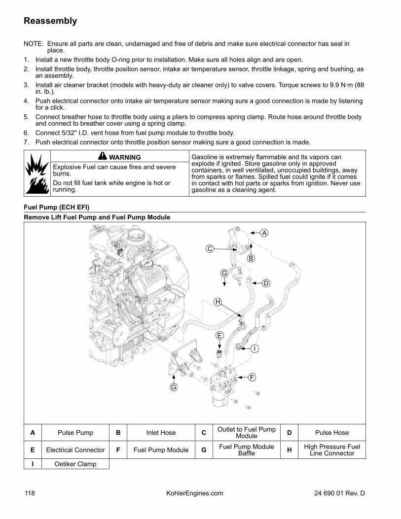
NOTE: Ensure all parts are clean, undamaged and free of debris and make sure electrical connector has seal in place.
1. Install a new throttle body O-ring prior to installation. Make sure all holes align and are open.2. Install throttle body, throttle position sensor, intake air temperature sensor, throttle linkage, spring and bushing, as
an assembly.3. Install air cleaner bracket (models with heavy-duty air cleaner only) to valve covers. Torque screws to 9.9 N·m (88
in. lb.).4. Push electrical connector onto intake air temperature sensor making sure a good connection is made by listening
for a click.5. Connect breather hose to throttle body using a pliers to compress spring clamp. Route hose around throttle body
and connect to breather cover using a spring clamp.6. Connect 5/32" I.D. vent hose from fuel pump module to throttle body.7. Push electrical connector onto throttle position sensor making sure a good connection is made.
WARNING Gasoline is extremely flammable and its vapors can explode if ignited. Store gasoline only in approved containers, in well ventilated, unoccupied buildings, away from sparks or flames. Spilled fuel could ignite if it comes in contact with hot parts or sparks from ignition. Never use gasoline as a cleaning agent.
Explosive Fuel can cause fires and severe burns.Do not fill fuel tank while engine is hot or running.
Fuel Pump (ECH EFI)Remove Lift Fuel Pump and Fuel Pump Module
B
G
A
E
G
C
D
F
H
I
A Pulse Pump B Inlet Hose C Outlet to Fuel Pump Module D Pulse Hose
E Electrical Connector F Fuel Pump Module G Fuel Pump Module Baffle H High Pressure Fuel
Line ConnectorI Oetiker Clamp
Reassembly
118 24 690 01 Rev. DKohlerEngines.com
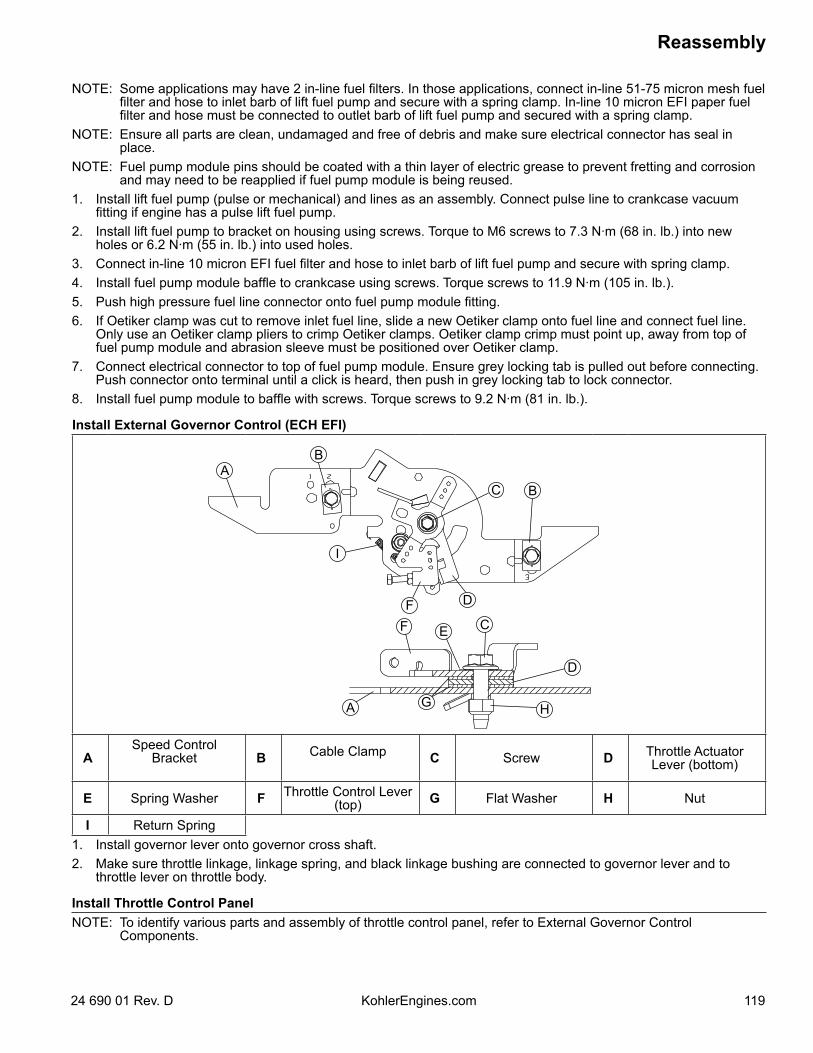
NOTE: Some applications may have 2 in-line fuel filters. In those applications, connect in-line 51-75 micron mesh fuel filter and hose to inlet barb of lift fuel pump and secure with a spring clamp. In-line 10 micron EFI paper fuel filter and hose must be connected to outlet barb of lift fuel pump and secured with a spring clamp.
NOTE: Ensure all parts are clean, undamaged and free of debris and make sure electrical connector has seal in place.
NOTE: Fuel pump module pins should be coated with a thin layer of electric grease to prevent fretting and corrosion and may need to be reapplied if fuel pump module is being reused.
1. Install lift fuel pump (pulse or mechanical) and lines as an assembly. Connect pulse line to crankcase vacuum fitting if engine has a pulse lift fuel pump.
2. Install lift fuel pump to bracket on housing using screws. Torque to M6 screws to 7.3 N·m (68 in. lb.) into new holes or 6.2 N·m (55 in. lb.) into used holes.
3. Connect in-line 10 micron EFI fuel filter and hose to inlet barb of lift fuel pump and secure with spring clamp.4. Install fuel pump module baffle to crankcase using screws. Torque screws to 11.9 N·m (105 in. lb.).5. Push high pressure fuel line connector onto fuel pump module fitting.6. If Oetiker clamp was cut to remove inlet fuel line, slide a new Oetiker clamp onto fuel line and connect fuel line.
Only use an Oetiker clamp pliers to crimp Oetiker clamps. Oetiker clamp crimp must point up, away from top of fuel pump module and abrasion sleeve must be positioned over Oetiker clamp.
7. Connect electrical connector to top of fuel pump module. Ensure grey locking tab is pulled out before connecting. Push connector onto terminal until a click is heard, then push in grey locking tab to lock connector.
8. Install fuel pump module to baffle with screws. Torque screws to 9.2 N·m (81 in. lb.).
Install External Governor Control (ECH EFI)
D
AB
C B
I
FF
D
E C
A G H
ASpeed Control
Bracket B Cable Clamp C Screw D Throttle Actuator Lever (bottom)
E Spring Washer F Throttle Control Lever (top) G Flat Washer H Nut
I Return Spring1. Install governor lever onto governor cross shaft.2. Make sure throttle linkage, linkage spring, and black linkage bushing are connected to governor lever and to
throttle lever on throttle body.
Install Throttle Control PanelNOTE: To identify various parts and assembly of throttle control panel, refer to External Governor Control
Components.
Reassembly
11924 690 01 Rev. D KohlerEngines.com
1. Prefill a new oil filter following instructions.2. Place new filter in shallow pan with open end up. Fill
with new oil until oil reaches bottom of threads. Allow 2 minutes for oil to be absorbed by filter material.
3. Apply a thin film of clean oil to rubber gasket on oil filter.
4. Refer to instructions on oil filter for proper installation.
5. Fill crankcase with new oil. Level should be at top of indicator on dipstick.
6. Reinstall oil fill cap/dipstick and tighten securely.
Connect Spark Plug LeadsConnect leads to spark plugs.
Prepare Engine for Operation (ECH EFI)NOTE: If ECU, throttle body, TPS or fuel pump module
were replaced, an ECU Reset and TPS Learn is required. Refer to Electrical System for ECU Reset and TPS Learn procedure.
Engine is now completely reassembled. Before starting or operating engine, be sure to do following.1. Make sure all hardware is tightened securely.2. Make sure oil drain plugs, Oil Sentry™ pressure
switch, and a new oil filter are installed.3. Verify crankcase has been filled with correct amount,
weight, and type of oil. Refer to oil recommendations and procedures in Maintenance, Specifications, and Lubrication System.
4. Adjust idle speed adjusting screw as necessary. Refer to Fuel System.
5. Turn on fuel supply.
1. Secure throttle control panel to crankcase with thread forming screws.
2. Attach governor spring to previously marked hole on governor lever.
Install Air Cleaner AssemblyRefer to Air Cleaner/Intake Air for air cleaner reassembly procedure.Heavy-Duty Air Cleaner1. Install air cleaner assembly onto throttle body
mounting studs. Secure with nuts and screws. Torque nuts to 7.4-9.0 N·m (65.5-80 in. lb.) and torque screws to 4.6-6.9 N·m (41-61 in. lb.).
Low-Profile Air Cleaner1. Verify O-ring is present around machined O.D. of
throttle body and place air cleaner base onto throttle body studs. Secure air cleaner base using nuts. Attach air cleaner base bracket to cylinder heads with screws behind any control panel or bracket. Attach air cleaner base to lower bracket with 2 M5 screws through lower section of base. Torque nuts to 6.2-7.3 N·m (55-65 in. lb.), and 2 lower M5 mounting screws (when applicable) to 4.0 N·m (35 in. lb.).
2. Install air cleaner components as described in Air Cleaner/Intake.
Setting Initial Governor Adjustment1. Move governor lever toward throttle body as far as it
will go (wide-open throttle) and hold in position.2. Insert a nail into hole on cross shaft and rotate shaft
counterclockwise as far as it will turn, then torque hex nut to 7.1 N·m (63 in. lb.).
Install Muffler1. Install port liners (if equipped). Install exhaust
gaskets and muffler. Install oxygen sensor, torque to 50.1 N·m (37 ft. lb.), and connect to wire harness.
2. Install muffler and attaching hardware to muffler bracket. Torque screws to 9.9 N·m (88 in. lb.).
3. Install nuts to exhaust studs. Torque nuts to 27.8 N·m (246 in. lb.).
Install Oil Cooler (if equipped)1. Secure adapter to closure plate with oil filter nipple.
Torque oil filter nipple to 28.5 N·m (21 ft. lb.).2. Verify all fuel and vent hoses are routed properly and
not pinched. Install 2 screws to blower housing. Torque screw between hoses to 2.3 N·m (20 in. lb.) and outer screw to 2.8 N·m (25 in. lb.).
Install Oil Filter and Fill Crankcase with OilNOTE: If testing oil pressure after completing
reassembly, install oil pressure adapter instead of oil filter.
Reassembly
120 24 690 01 Rev. DKohlerEngines.com
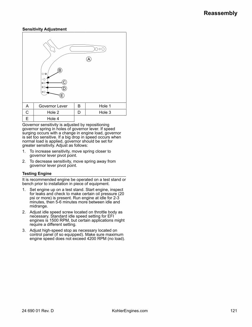
Sensitivity Adjustment
B
A
CD
E
A Governor Lever B Hole 1C Hole 2 D Hole 3E Hole 4
Governor sensitivity is adjusted by repositioning governor spring in holes of governor lever. If speed surging occurs with a change in engine load, governor is set too sensitive. If a big drop in speed occurs when normal load is applied, governor should be set for greater sensitivity. Adjust as follows:1. To increase sensitivity, move spring closer to
governor lever pivot point.2. To decrease sensitivity, move spring away from
governor lever pivot point.
Testing EngineIt is recommended engine be operated on a test stand or bench prior to installation in piece of equipment.1. Set engine up on a test stand. Start engine, inspect
for leaks and check to make certain oil pressure (20 psi or more) is present. Run engine at idle for 2-3 minutes, then 5-6 minutes more between idle and midrange.
2. Adjust idle speed screw located on throttle body as necessary. Standard idle speed setting for EFI engines is 1500 RPM, but certain applications might require a different setting.
3. Adjust high-speed stop as necessary located on control panel (if so equipped). Make sure maximum engine speed does not exceed 4200 RPM (no load).
Reassembly
12124 690 01 Rev. D KohlerEngines.com

Reassembly
122 24 690 01 Rev. DKohlerEngines.com

Reassembly
12324 690 01 Rev. D KohlerEngines.com

124 24 690 01 Rev. DKohlerEngines.com
© 2011 by Kohler Co. All rights reserved.