ECET 211 Electric Machines & Controls Lecture 4-1 … 211 Electric Machines & Controls Lecture 4-1...
16
1 1 ECET 211 Electric Machines & Controls Lecture 4-1 Motor Control Devices: Part 1. Manually Operated Switch Part 2. Mechanically Operated Switch Text Book: Electric Motors and Control Systems, by Frank D. Petruzella, published by McGraw Hill, 2015. Paul I-Hai Lin, Professor of Electrical and Computer Engineering Technology P.E. States of Indiana & California Dept. of Computer, Electrical and Information Technology Purdue University Fort Wayne Campus Prof. Paul Lin Lecture 4 Motor Control Devices Chapter 4. Motor Control Devices • Part 1. Manually Operated Switches • Part 2. Mechanically Operated Switches • Part 3. Sensors • Part 4. Actuators Prof. Paul Lin 2
Transcript of ECET 211 Electric Machines & Controls Lecture 4-1 … 211 Electric Machines & Controls Lecture 4-1...

1
1
ECET 211 Electric Machines & Controls
Lecture 4-1 Motor Control Devices: Part 1. Manually Operated Switch
Part 2. Mechanically Operated Switch
Text Book: Electric Motors and Control Systems, by Frank D. Petruzella,
published by McGraw Hill, 2015.
Paul I-Hai Lin, Professor of Electrical and Computer Engineering
Technology
P.E. States of Indiana & California
Dept. of Computer, Electrical and Information Technology
Purdue University Fort Wayne Campus
Prof. Paul Lin
Lecture 4 Motor Control Devices
Chapter 4. Motor Control Devices
• Part 1. Manually Operated Switches
• Part 2. Mechanically Operated Switches
• Part 3. Sensors
• Part 4. Actuators
Prof. Paul Lin 2

2
Part 1. Manually Operated Switches
Primary and Pilot Control Devices
Toggle Switches
Push Button Switches
Pilot Lights
Selector Switch
Drum Switch
Prof. Paul Lin 3
Manually Operated Switches
Primary and Pilot Control Devices
Control device
• A component that governs the electric
power delivery to an electrical load
• Must be capable of handling the voltage
and current to be switched
Prof. Paul Lin 4
Two classes of control devices: Primary control and Pilot
control device
Primary control device:
• Motor contactor, Starter, or Controller that connect the load
to the line
• Contactor can also be used as pilot control device
Pilot control device:
• Relay, Switch contact that used to activate the primary
control device
• Should not be used to switch horsepower load

3
Manually Operated Switches – Push Button SW
Figure 4-1 Primary and Pilot Control
Devices
• A typical motor control switch that
include both a Primary Control
(contactor), and a Pilot Control
device (toggle switch)
• Theory of operation
1. Turn toggle switch on to
complete the control circuit:
Power source (L1, L2) Toggle
switch Contactor’s coil M
2. Contactor energized => close
the M’s NO contacts => Deliver
power to the Motor
3. Turn toggle switch off =>
Contact M de-energized => the
M’s NO contacts open => Motor
stop Prof. Paul Lin 5
Manually Operated Switches – Toggle Switches
Types of toggle switch
• SPST – Single pole, single throw
• SPDT – Single pole, double throw
• DPST – Double pole, double throw
• DPDT – Double pole, double throw
Figure 4-2 Toggle switches
Electrical Rating for Switches
• Maximum interrupting voltage and current
• AC rating higher than DC rating for an equivalent amount of
voltage
• AC current is at zero level twice during each cycle
Prof. Paul Lin 6

4
AC 120V 60Hz Since Wave
% sine120v.m
% MATLAB simulation
% 2014/1/13
% By Paul Lin
f = 60; %Frequency in Hz
T = 1/f; %Period in Second
dt = T/100; %Samlping time interval
Vrms = 120; % Root Mean Square voltage
t = 0: dt: 2*T; % Time vector
theta = 0; % Initial offset angle
e = 120*sqrt(2)*sin(2*pi*f*t + theta); % Voltage equation
% e = 120*1.414*sin(2*pi*f*t + theta); % Voltage equation
plot(t, e), grid on; %Plot the voltage waveform
xlabel('time Second'), ylabel('Volts')
Prof. Paul Lin 7
0 0.005 0.01 0.015 0.02 0.025 0.03 0.035-200
-150
-100
-50
0
50
100
150
200
time Second
Volts
Manually Operated Switches – Push Buttons
NO Push button (Normally open) –
START
NC Push button (Normally close) –
STOP
Break-Make Push button – NC contact
on the top section, NO contact on the
bottom section
Application example2
• 1) Motor starting/stopping control
• 2) Control and override process
functions
Prof. Paul Lin 8
Figure 4-3 Pushbutton
symbols and switching action
Figure 4-5 Pushbutton station – NEMA type 1
5
Manually Operated Switches – Pushbutton SW
Figure 4-4 Break-make push button
and typical motor control circuit
Jogging Application – Momentary
operation to give small movement of a
driven machine.
1) Start PB pushed => M coil
energized => Motor running;
contact M is closed and
remembering the Start operation
2) Push down the Jog PB
momentary, M coil de-energized,
Motor stopped;
3) Then when Jog PB is pressed all
the way down, it then energize M
coil again and contact M is also
closed again
Prof. Paul Lin 9
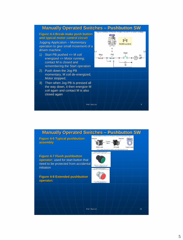
Manually Operated Switches – Pushbutton SW
Figure 4-6 Typical pushbutton
assembly
Figure 4-7 Flush pushbutton
operator: used for start button that
need to be protected from accidental
initiation
Figure 4-8 Extended pushbutton
operator:
Prof. Paul Lin 10

6
Manually Operated Switches – Pushbutton SW
Figure 4-9 Mushroom head
pushbutton operator: easily seen
and actuated, used as emergency
stop PBs
E-Stop
Emergency Stop Pushbutton White
Paper, 2012,
http://literature.rockwellautomation.
com/idc/groups/literature/document
s/wp/800-wp008_-en-p.pdf
Prof. Paul Lin 11
Manually Operated Switches – Pushbutton SW
Figure 4-10 Half-rounded
pushbutton operator
Figure 4-11 Illuminated
pushbutton operator: LED
integrated
Figure 4-13 Pushbutton assembly
Legend Plates (Labels) for
Pushbuttons: START, STOP, FWD,
REV, JOG, UP, DOWN, ON, OFF,
RESET, and RUN
Prof. Paul Lin 12

7
OSHA Safety Requirement: Emergency Stop Pushbutton
OSHA requirements on Emergency Stop: Requires that once
the emergency stop switch has activated, the control process cannot be
started again until the actuating stop switch has been reset to the on
position.
• Safeguarding Equipment and Protecting Employee from
Amputation, 2007,
https://www.osha.gov/Publications/osha3170.pdf
• Section IV: Chapter 4 Industrial Robots and Robot System
Safety, OSHA Technical Manual,
https://www.osha.gov/dts/osta/otm/otm_iv/otm_iv_4.html
Other References
Electrical Requirements, Safeguarding Cutting and
Turning Machine – The Safety Library,
http://www.readbag.com/sti-ltr2-access-php-5
Prof. Paul Lin 13
Emergency Stop Pushbutton
Figure 4-14 Emergency Stop
Pushbutton – motor control circuit
Theory of Operation
An Emergency Stop PB is added
(in series) with the typical
START/STOP motor control circuit
The normally closed maintained
contacts of the Emergency Stop
push button will open when the
push button is pressed and remain
open until its is manually reset.
Motor will not operate
To restart the motor, you must first
reset the emergency PB, and then
press the Start button
Prof. Paul Lin 14

8
Mechanically Operated Switches – Pilot Lights
Pilot Lights
• provide visual indication of the
status for many motor-controlled
processes permitting personnel at
remote locations to observe the
current state of the operation.
• Full-voltage type – with
transformers (Figure 4-16)
• Low-voltage type – operate at 6 to
24 V, AC or DC
Figure 4-15 Remote start/stop station
with run pilot light
Prof. Paul Lin 15
Mechanically Operated Switches – Pilot Lights
Figure 4-17 Push-to-test pilot
light
• Designed to reduce the time
required to troubleshoot a
suspected faulty lamp.
Theory of Operation
1) Normal operation – R light on
2) If R light out, push and release
the Push-to-test light to see if the R
light is at fault rather that the motor
control circuit.
Prof. Paul Lin 16

9
Selector Switch
Selector Switch
A rotated switch for opening and
closing contacts of the attached
contact block
Operator knob:
• turning right or left
• May have two or more
selector positions
Figure 4-17 Three-position
selector switch: Pump Control
• Hand – it allows for manual
control via Manual Control
Switch
• Auto – It allow only for pump
to be control via Liquid-level
switch
• Off
Prof. Paul Lin 17
Drum Switch
A drum switch consists of a set of
moving contacts and a set secondary
contacts that open and as close as the
shaft is rotated
Figure 4-19 Drum switch used for
reversing the direction of rotation of
a three-phase motor
• FWD position
T1 L1
T2 L2
T3 L3
• REV position
T1 L1
T2 L3
T3 L2
Prof. Paul Lin 18

10
Part 2 Mechanically Operated Switches
Limit Switches
• A mechanically operated switch is
one that is controlled automatically
by factor such pressure, position,
and temperature
• Designed to operate only when a
predetermined limit is reached
• Often used in the control circuits of
machine processes to govern the
Starting, Stopping, or Reversal of
motors
Temperature Control Devices
Pressure Switches
Float and Flow Switches
Prof. Paul Lin 19
Part 2 Mechanically Operated Switches Limit Switches
• Two parts: the body
and the operator
head (actuator)
• Contact types
NO, NC,
Momentary
(spring returned),
Maintained-
contact type
Prof. Paul Lin 20

11
Limit Switches Figure 4-12 Limit
switch symbols and
configuration
• NEMA Symbols
• IEC Symbols
• A limit switch with
both NO and NC
contacts, you must
wire the Load on the
same side of line;
and be sure to form a
COM on the line side
Prof. Paul Lin 21
COM
Limit Switches Figure 4-12 Limit switch operator
• Level type
• Fork type
• Wobble stick
• Push roller
Prof. Paul Lin 22
COM
12
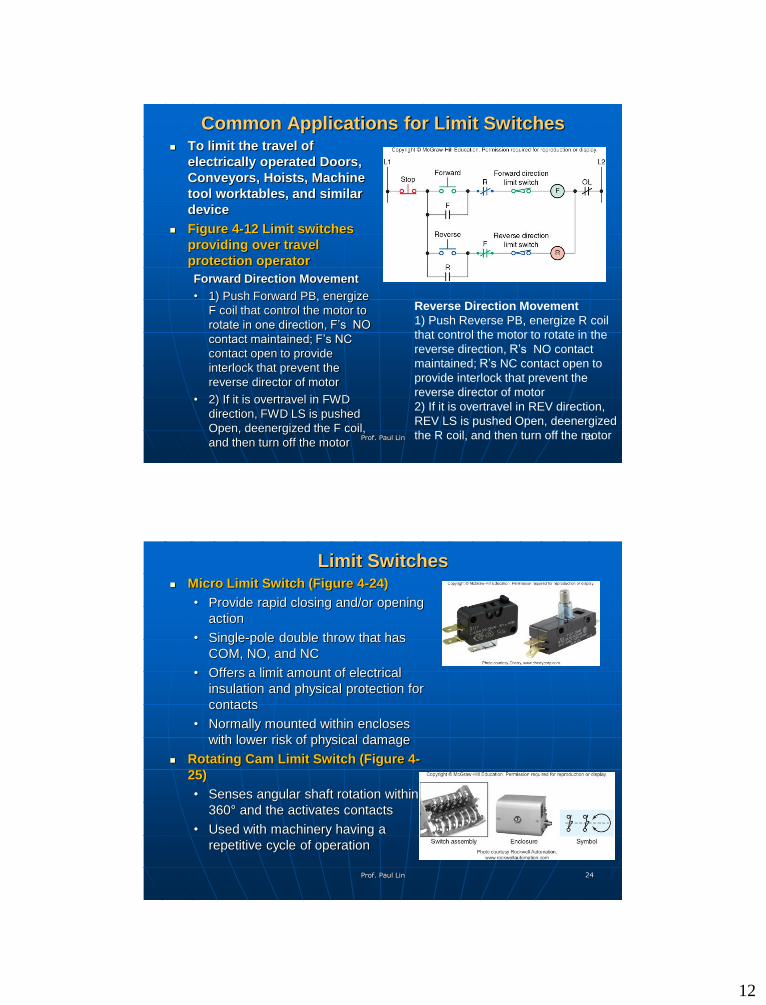
Common Applications for Limit Switches To limit the travel of
electrically operated Doors,
Conveyors, Hoists, Machine
tool worktables, and similar
device
Figure 4-12 Limit switches
providing over travel
protection operator
Forward Direction Movement
• 1) Push Forward PB, energize
F coil that control the motor to
rotate in one direction, F’s NO
contact maintained; F’s NC
contact open to provide
interlock that prevent the
reverse director of motor
• 2) If it is overtravel in FWD
direction, FWD LS is pushed
Open, deenergized the F coil,
and then turn off the motor
Prof. Paul Lin 23
Reverse Direction Movement
1) Push Reverse PB, energize R coil
that control the motor to rotate in the
reverse direction, R’s NO contact
maintained; R’s NC contact open to
provide interlock that prevent the
reverse director of motor
2) If it is overtravel in REV direction,
REV LS is pushed Open, deenergized
the R coil, and then turn off the motor
Limit Switches Micro Limit Switch (Figure 4-24)
• Provide rapid closing and/or opening
action
• Single-pole double throw that has
COM, NO, and NC
• Offers a limit amount of electrical
insulation and physical protection for
contacts
• Normally mounted within encloses
with lower risk of physical damage
Rotating Cam Limit Switch (Figure 4-
25)
• Senses angular shaft rotation within
360° and the activates contacts
• Used with machinery having a
repetitive cycle of operation
Prof. Paul Lin 24
13
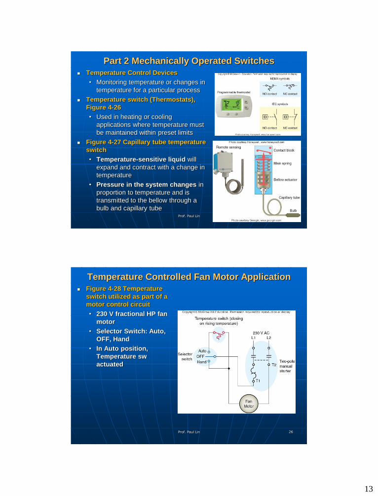
Part 2 Mechanically Operated Switches
Temperature Control Devices
• Monitoring temperature or changes in
temperature for a particular process
Temperature switch (Thermostats),
Figure 4-26
• Used in heating or cooling
applications where temperature must
be maintained within preset limits
Figure 4-27 Capillary tube temperature
switch
• Temperature-sensitive liquid will
expand and contract with a change in
temperature
• Pressure in the system changes in
proportion to temperature and is
transmitted to the bellow through a
bulb and capillary tube
Prof. Paul Lin 25
Temperature Controlled Fan Motor Application
Figure 4-28 Temperature
switch utilized as part of a
motor control circuit
• 230 V fractional HP fan
motor
• Selector Switch: Auto,
OFF, Hand
• In Auto position,
Temperature sw
actuated
Prof. Paul Lin 26

14
Part 2 Mechanically Operated Switches
Pressure Switches
• Used to monitor and control the
pressure of liquids and gases
• Pressure => activate electrical
contacts
• Three types
Positive pressure
Vacuum (negative pressure)
Differential pressure
• Figure 4-29 Pressure switch
symbols
Prof. Paul Lin 27
Part 2 Mechanically Operated Switches
Theory of Operation
1) Pressure sw with high cut off and low
turn on differential setting (dean band)
is preselected
2) System on/off sw is set to on position
=> energize Compressor motor starter
coil => Motor is on
3) Compressor system pressure is
reached, Pressure sw off, de-energize
M coil => Motor stopped
4) Compressor system pressure
dropped below the low level =>
Pressure sw On, M coil energized again
=> Motor start to run again
5) Repeat step 3 through 4
Prof. Paul Lin 28
Figure 4-30 Pressure switch used as
part of air-compressor control
system
15
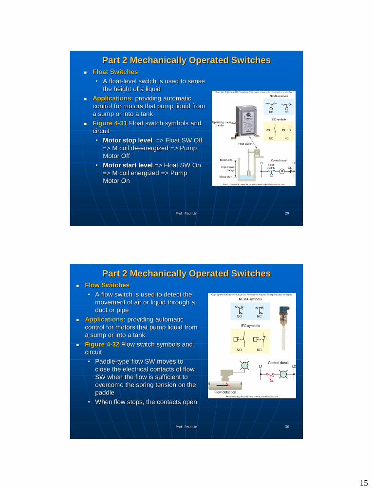
Part 2 Mechanically Operated Switches
Float Switches
• A float-level switch is used to sense
the height of a liquid
Applications: providing automatic
control for motors that pump liquid from
a sump or into a tank
Figure 4-31 Float switch symbols and
circuit
• Motor stop level => Float SW Off
=> M coil de-energized => Pump
Motor Off
• Motor start level => Float SW On
=> M coil energized => Pump
Motor On
Prof. Paul Lin 29
Part 2 Mechanically Operated Switches
Flow Switches
• A flow switch is used to detect the
movement of air or liquid through a
duct or pipe
Applications: providing automatic
control for motors that pump liquid from
a sump or into a tank
Figure 4-32 Flow switch symbols and
circuit
• Paddle-type flow SW moves to
close the electrical contacts of flow
SW when the flow is sufficient to
overcome the spring tension on the
paddle
• When flow stops, the contacts open
Prof. Paul Lin 30
16
Summary & Conclusion
Questions? Contact Prof. Lin through:
Email: [email protected]
LINE Group discussion forum
Prof. Paul Lin 31