ECE795 - Lecture #1.ppt
70
ECE 795: Quantitative Electrophysiology Notes for Lecture #1 Monday, September 20, 2010
Transcript of ECE795 - Lecture #1.ppt
ECE 795:
Quantitative ElectrophysiologyNotes for Lecture #1
Monday, September 20, 2010
2
1. INTRODUCTION TO EXCITABLE CELLS
Historical perspective:
Bioelectricity first discovered by Luigi Galvani in 1780s
Originally termed “animal electricity”
Galvani thought that a special electrical fluid was prepared by the brain, flowing through the nerve tubes into muscles
3
Modern perspective:
Bioelectricity is now known to obey the same fundamental laws of electricity in the atmosphere, conducting wires, semiconductors, etc.
However, there are some substantial differences between bioelectrical systems and man-made electrical systems.
4
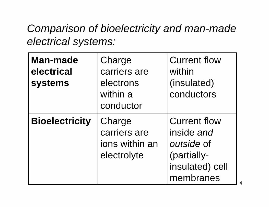
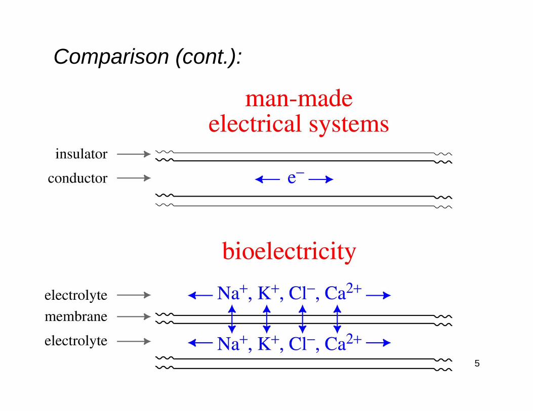
Comparison of bioelectricity and man-made electrical systems:
Man-made electrical systems
Charge carriers are electrons within a conductor
Current flow within (insulated) conductors
Bioelectricity Charge carriers are ions within an electrolyte
Current flow inside and outside of (partially-insulated) cell membranes
5
Comparison (cont.):
6
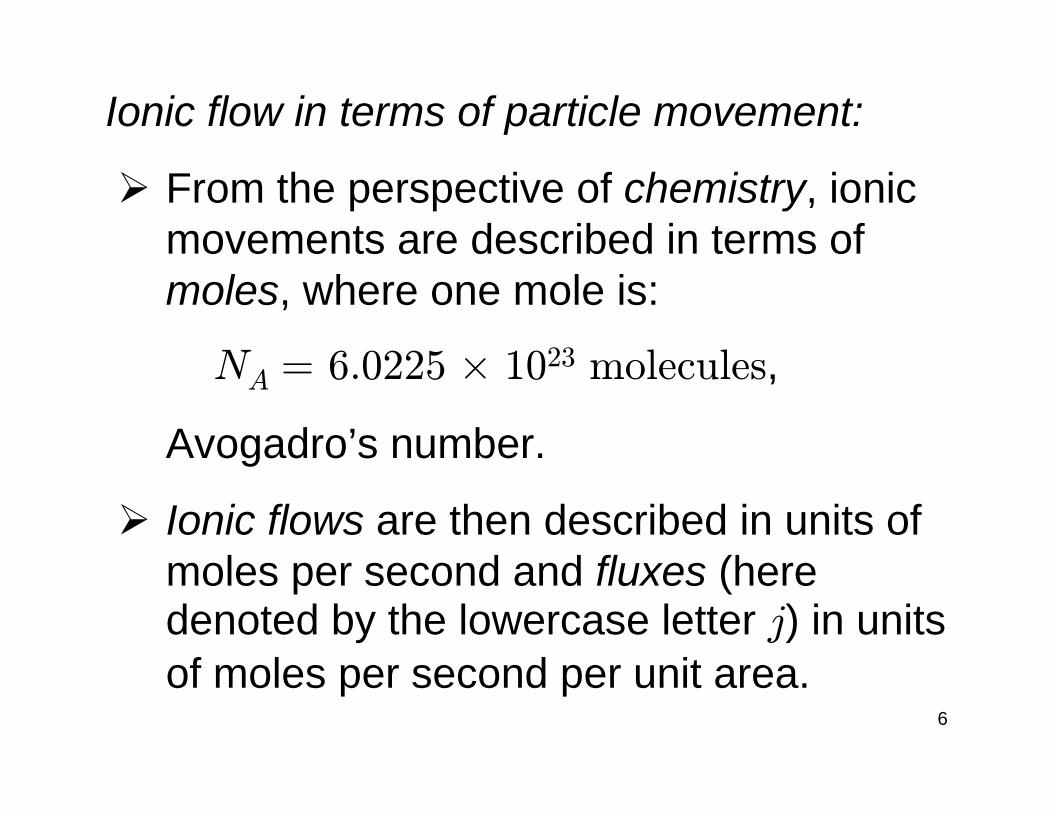
Ionic flow in terms of particle movement:
From the perspective of chemistry, ionic movements are described in terms of moles, where one mole is:
NA = 6.0225 × 10²³ molecules,
Avogadro’s number.
Ionic flows are then described in units of moles per second and fluxes (here denoted by the lowercase letter j) in units of moles per second per unit area.
7
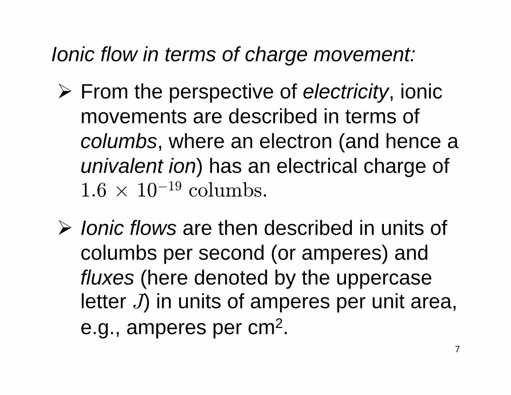
Ionic flow in terms of charge movement:
From the perspective of electricity, ionic movements are described in terms of columbs, where an electron (and hence a univalent ion) has an electrical charge of 1.6 × 10⁻¹⁹ columbs.
Ionic flows are then described in units of columbs per second (or amperes) and fluxes (here denoted by the uppercase letter J) in units of amperes per unit area, e.g., amperes per cm2.
8
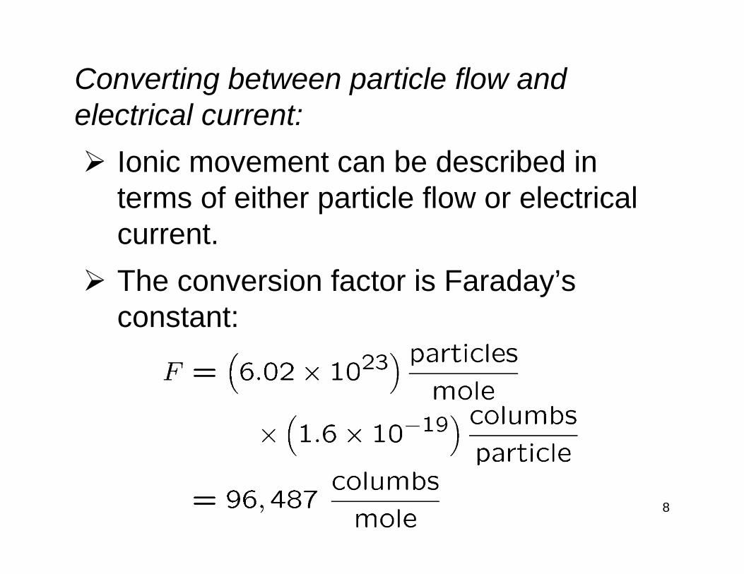
Converting between particle flow and electrical current:
Ionic movement can be described in terms of either particle flow or electrical current.The conversion factor is Faraday’s constant:
9
Excitable cells:
Cells that can generate electrical potentials and currents are referred to as excitable cells.
These potentials and currents can be observed in the cells’ interior volume, across their membranes, and in their surrounding conducting volume.
Excitable cells include nerve cells(neurons), muscle fibers, and sensory receptor (transducer) cells.
10
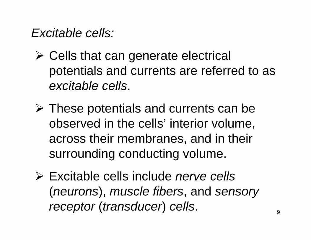
(from Johnstonand Wu)
Nerve cells:
11
(from Johnstonand Wu)
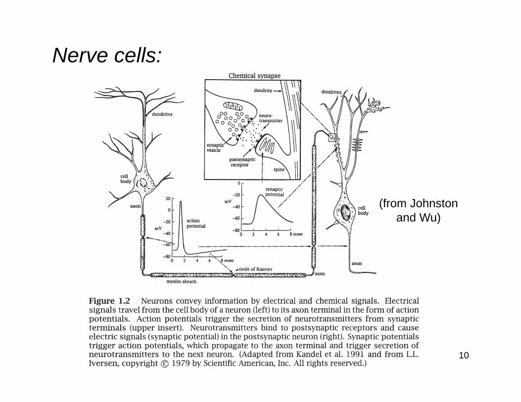
Examples of neuron morphologies:
12
(from Guyten)
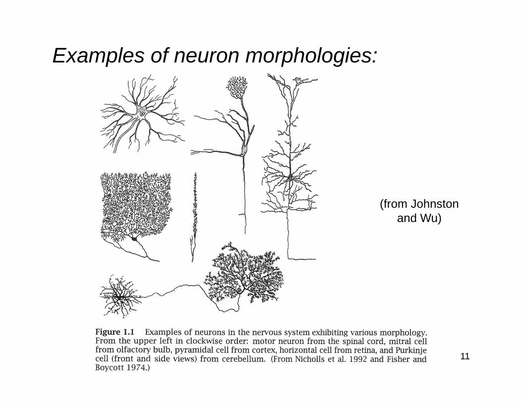
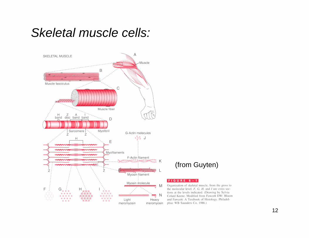
Skeletal muscle cells:

13
(from Guyten)
Transverse tubule-sarcoplasmic reticulum system for excitation-contraction coupling:
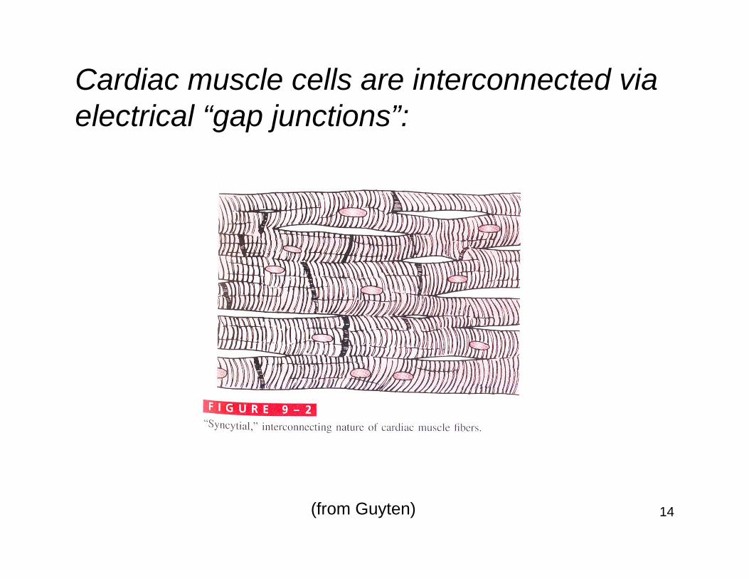
14(from Guyten)
Cardiac muscle cells are interconnected via electrical “gap junctions”:
15
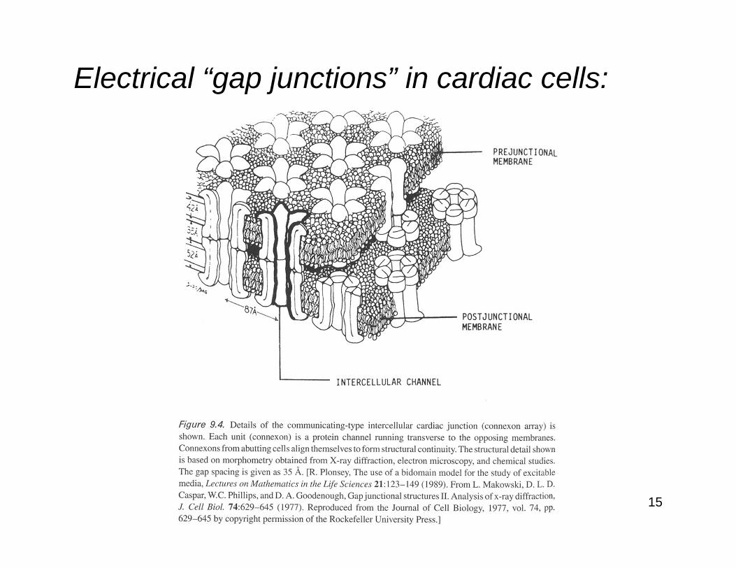
Electrical “gap junctions” in cardiac cells:
16(from Guyten)
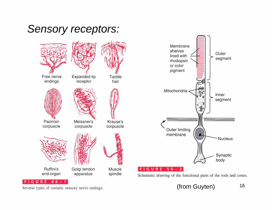
Sensory receptors:
17
(from Guyten)
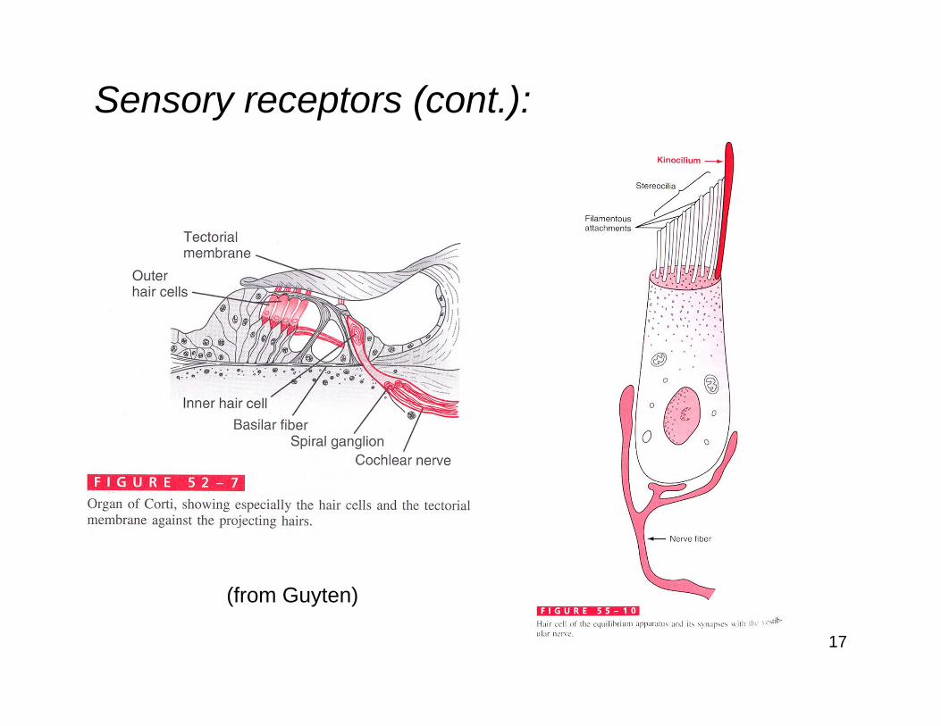
Sensory receptors (cont.):
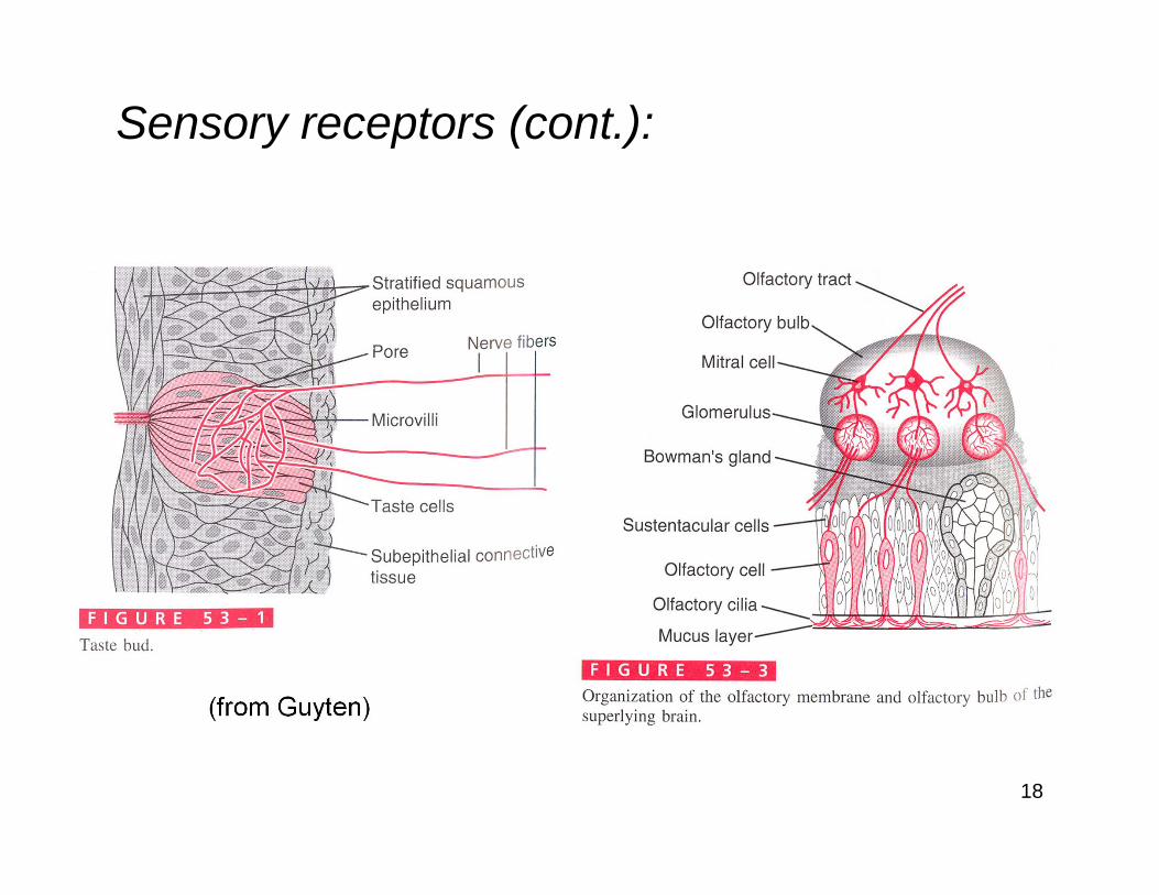
18
(from Guyten)
Sensory receptors (cont.):
19
2. EQUIVALENT ELECTRICAL CIRCUITS FOR CELL MEMBRANES
We will look at:
Ionic composition of excitable cells
Nernst-Planck equation
Membrane structure
Nernst potential
Parallel-conductance model

20
Ionic composition of excitable cells:Sodium (Na+) and potassium (K+) are the most important ions for the electrical activity of the majority of excitable cells.Calcium (Ca2+) and chloride (Cl−) play a significant role in some circumstances.Many of the fundamental properties of ionic movement are the same no matter which ion is being considered.Consequently, we will often derive mathematical expressions for “the pth
ion”.
21
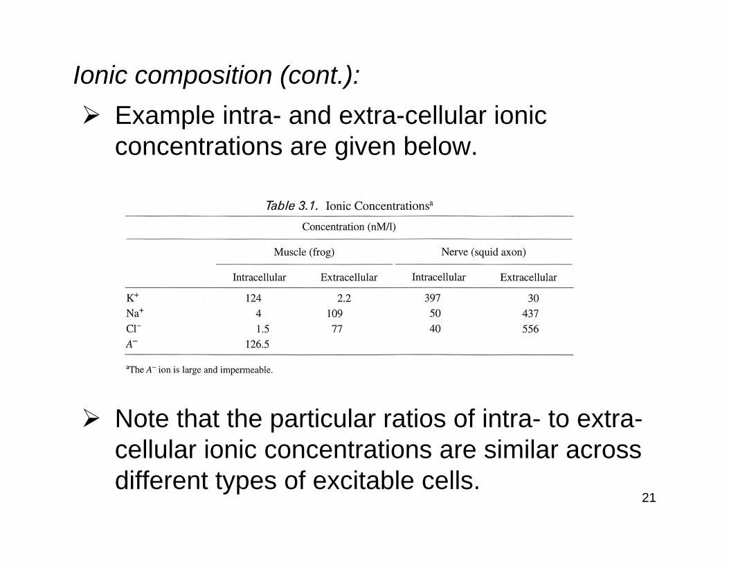
Ionic composition (cont.):Example intra- and extra-cellular ionic concentrations are given below.
Note that the particular ratios of intra- to extra-cellular ionic concentrations are similar across different types of excitable cells.
22
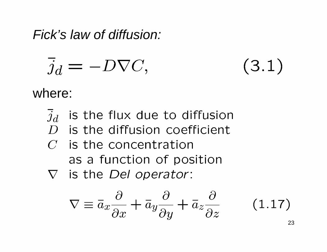
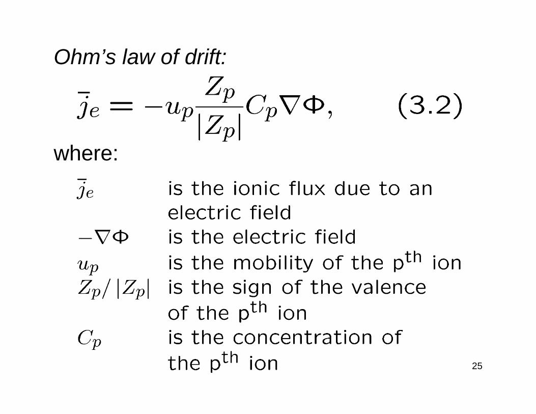
Nernst-Planck Equation:The Nernst-Planck equation describes the effects of spatial differences in concentration and/or electric potential on ion flow.The individual effect of a concentration gradient is described by Fick’s law of diffusion.The individual effect of an electric potential gradient is described by Ohm’s law of drift.
23
Fick’s law of diffusion:
where:
24
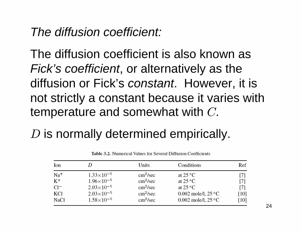
The diffusion coefficient:
The diffusion coefficient is also known as Fick’s coefficient, or alternatively as the diffusion or Fick’s constant. However, it is not strictly a constant because it varies with temperature and somewhat with C.
D is normally determined empirically.
25
Ohm’s law of drift:
where:
26
Relating diffusion and drift:
Diffusion and drift are impeded by the same molecular processes, i.e., collisions with solvent molecules, and consequently a physical connection exists between the parameters up and D.
The mathematical expression for this relationship is known as Einstein’s equation.

27
Einstein’s equation:
where:
28
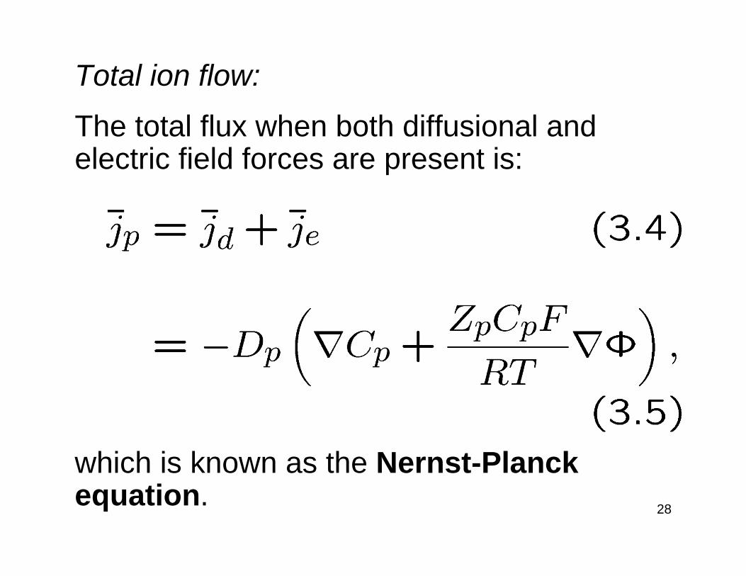
Total ion flow:
The total flux when both diffusional and electric field forces are present is:
which is known as the Nernst-Planck equation.
29
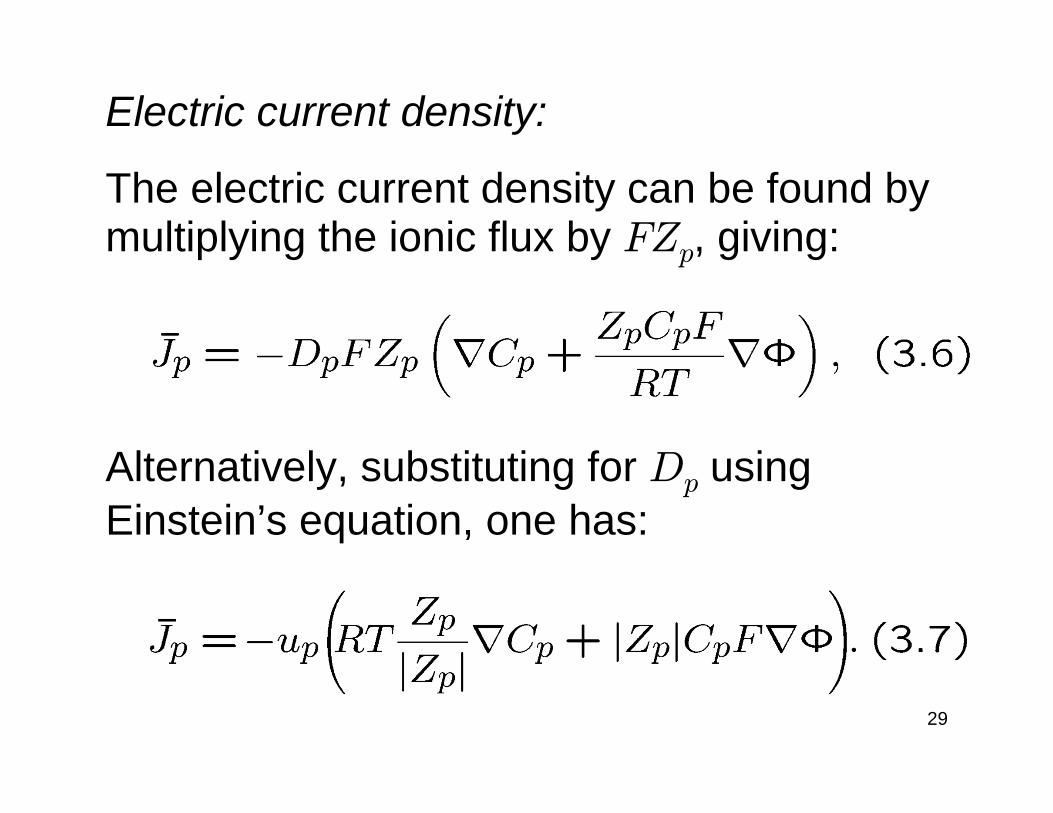
Electric current density:
The electric current density can be found by multiplying the ionic flux by FZp, giving:
Alternatively, substituting for Dp using Einstein’s equation, one has:
30
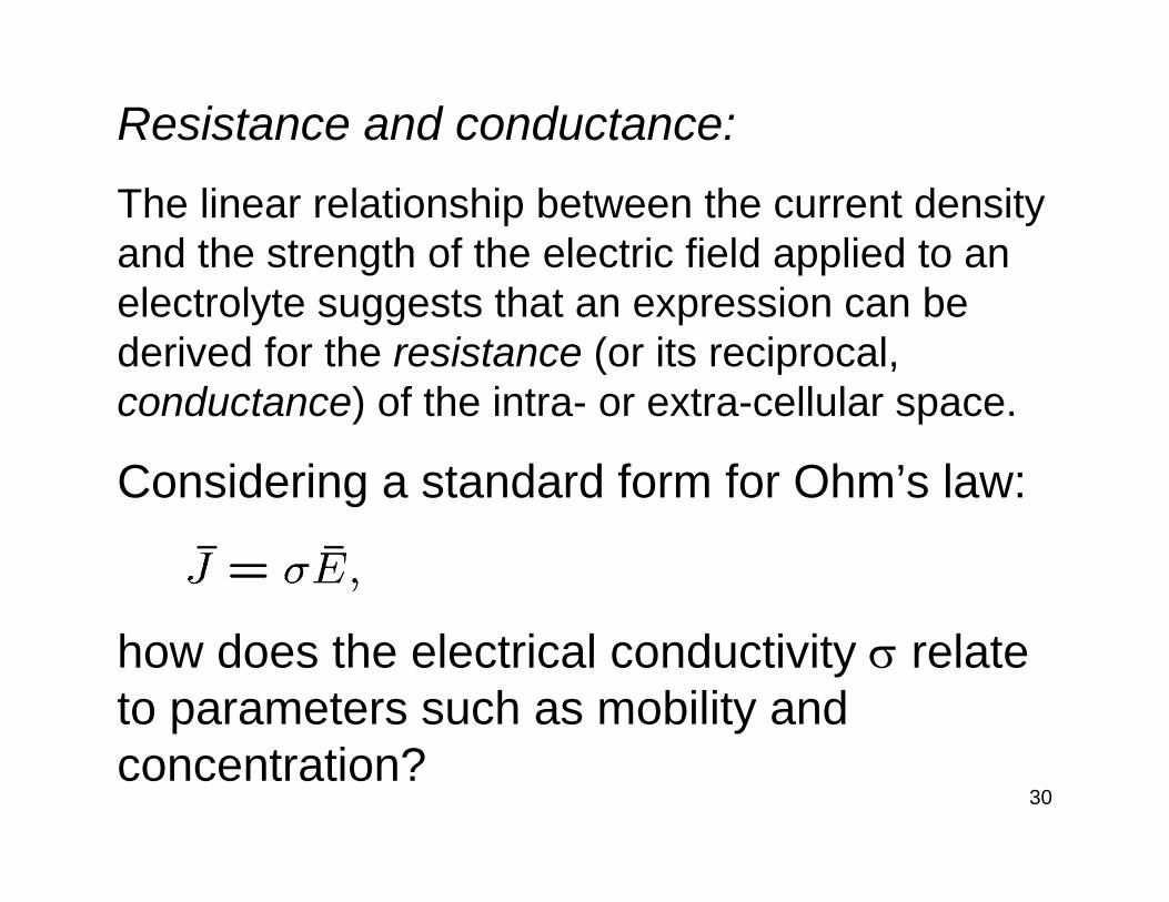
Resistance and conductance:The linear relationship between the current density and the strength of the electric field applied to an electrolyte suggests that an expression can be derived for the resistance (or its reciprocal, conductance) of the intra- or extra-cellular space.
Considering a standard form for Ohm’s law:
how does the electrical conductivity σ relate to parameters such as mobility and concentration?
31
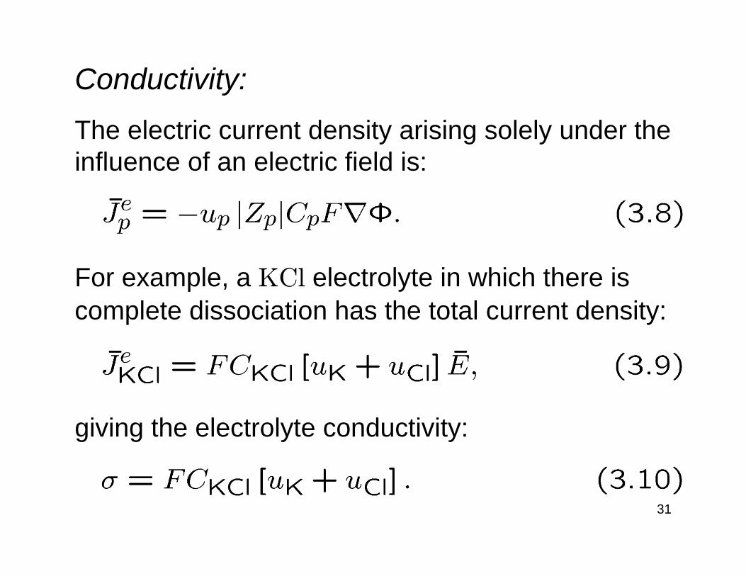
Conductivity:The electric current density arising solely under the influence of an electric field is:
For example, a KCl electrolyte in which there is complete dissociation has the total current density:
giving the electrolyte conductivity:
32
Membrane structure:
Excitable cells are surrounded by a plasma membrane consisting of a lipid bilayer.
The passage of ions through the membrane is regulated by:
1. Pumps and exchangers
2. Channels
33
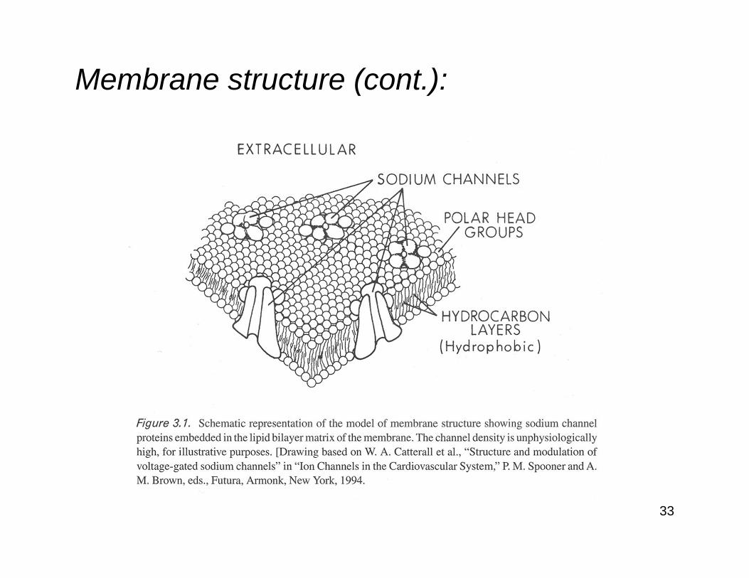
Membrane structure (cont.):

34
Pumps and exchangers:Pumps are active processes (i.e., they consume energy) that move ions against the concentration gradients.Exchangers use the concentration gradient of one ion to move another ion against its concentration gradient.The purpose of pumps and exchangers is to maintain the different intra- and extra-cellular ionic concentrations.The major ion transporters are: Na+-K+ pump, Na+-Ca2+ exchanger, Ca2+ pump, Bicarbonate-Cl− exchanger, Cl−-Na+-K+ cotransporter.
35
Channels:Channels are passive processes that allow ions to pass through the membrane under the influence of concentration and electric potential gradients.Channels exhibit selective permeability, i.e., they only allow certain ions to pass through them.Ion channel gates regulate the permeability of channels, allowing control over the flow of particular ions.

36
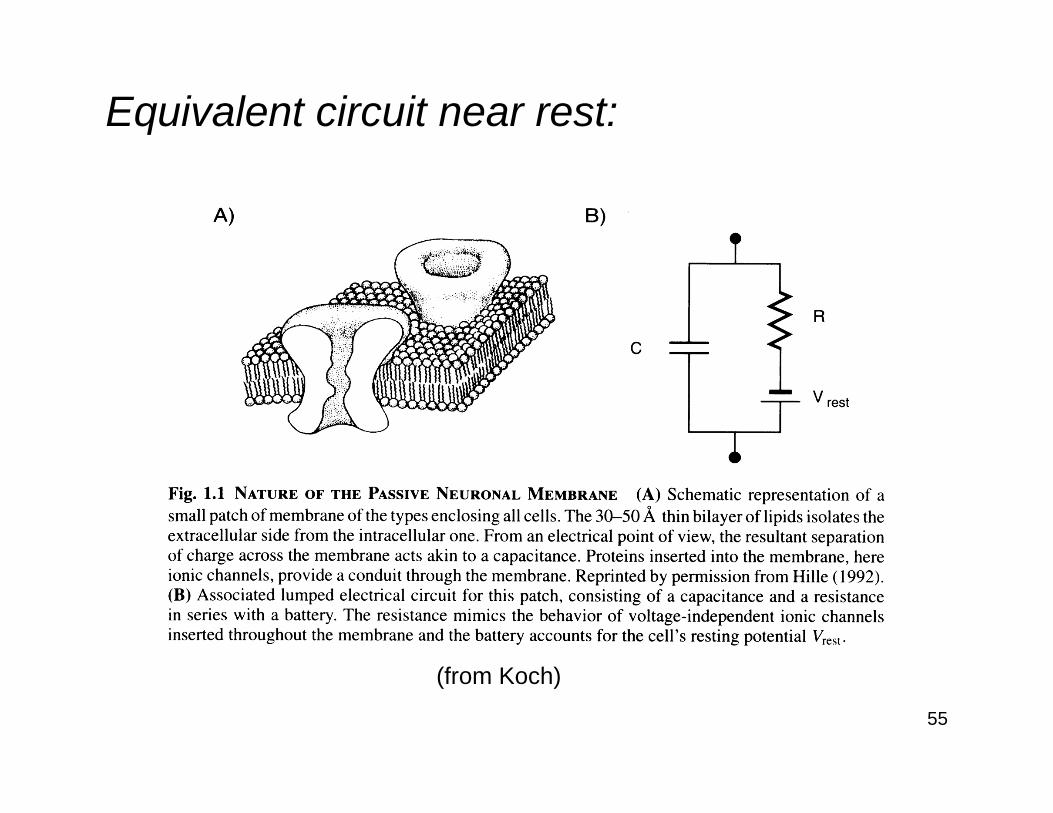
Membrane capacitance:The lipid membrane itself has a specific resistance of 109 Ω·cm2, i.e., it is effectively an insulator.Consequently, charge can build up on each side of the membrane in regions where there are no channels or where channels are closed.Because of the thinness of the membrane, it acts as a capacitor, with a capacitance typically aroundCm = 0.9 μF/cm2.
37
Ion flow through open channels:From the Nernst-Planck equation, the flow of the pth ion will depend on both the concentration gradient of the pth ion and an electric potential gradient.For an excitable cell, the unequal concentration of ions in the intra- versus extra-cellular spaces produces ion flow through any open ion channels.Ions will accumulate on the membrane because of its capacitance, producing an electrical field across and within the membrane that will in turn exert a force on all charged particles within ion channels.
38
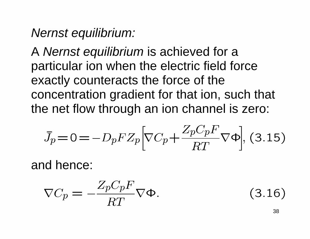
Nernst equilibrium:A Nernst equilibrium is achieved for a particular ion when the electric field force exactly counteracts the force of the concentration gradient for that ion, such that the net flow through an ion channel is zero:
and hence:
39
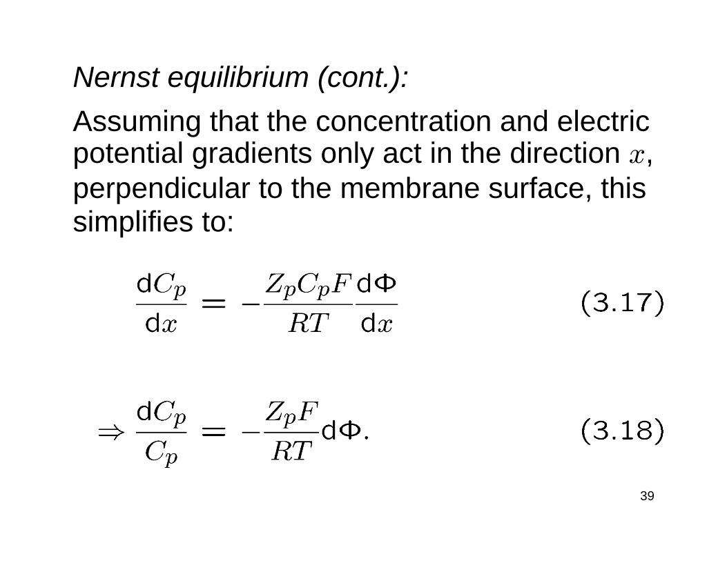
Nernst equilibrium (cont.):Assuming that the concentration and electric potential gradients only act in the direction x, perpendicular to the membrane surface, this simplifies to:
40
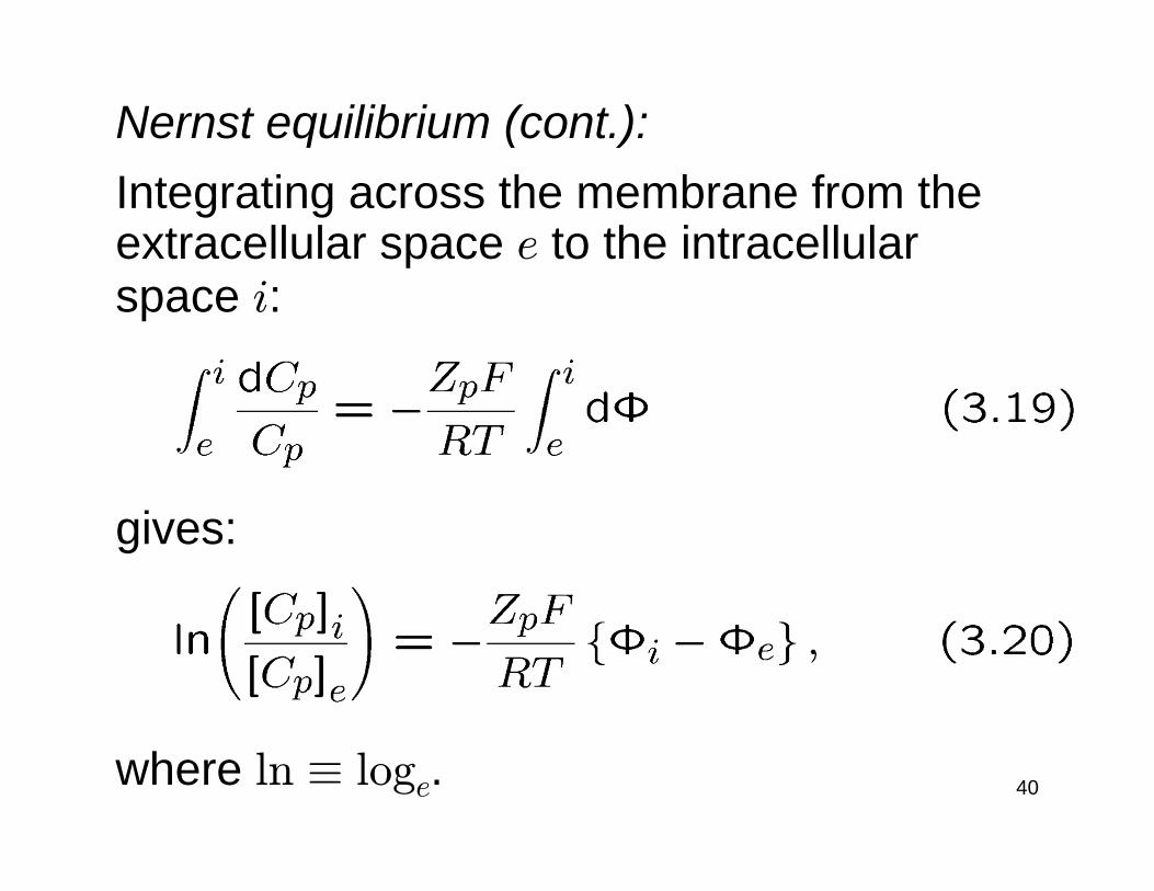
Nernst equilibrium (cont.):Integrating across the membrane from the extracellular space e to the intracellular space i:
gives:
where ln ≡ loge.
41
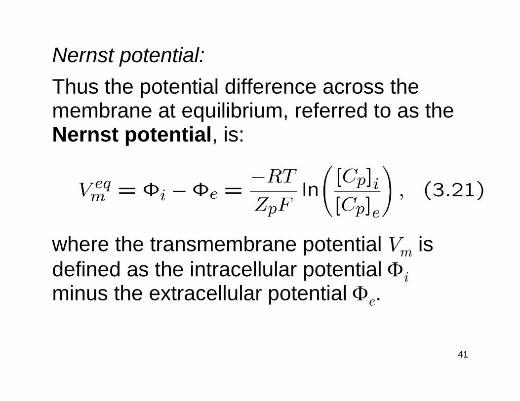
Nernst potential:Thus the potential difference across the membrane at equilibrium, referred to as the Nernst potential, is:
where the transmembrane potential Vm is defined as the intracellular potential Φi
minus the extracellular potential Φe.
42
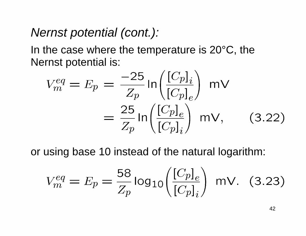
Nernst potential (cont.):In the case where the temperature is 20°C, the Nernst potential is:
or using base 10 instead of the natural logarithm:
43
Equilibrium/reversal potentials:The Nernst potential for a particular ion is often referred to as the equilibrium potentialand is given the symbol Ep.For example, the equilibrium potentials for sodium and potassium ions are given the symbols ENa and EK, respectively.The equilibrium potential is also sometimes referred to as the reversal potential, because at this potential the direction of the ionic current reverses from inwards to outwards, or vice versa.
44
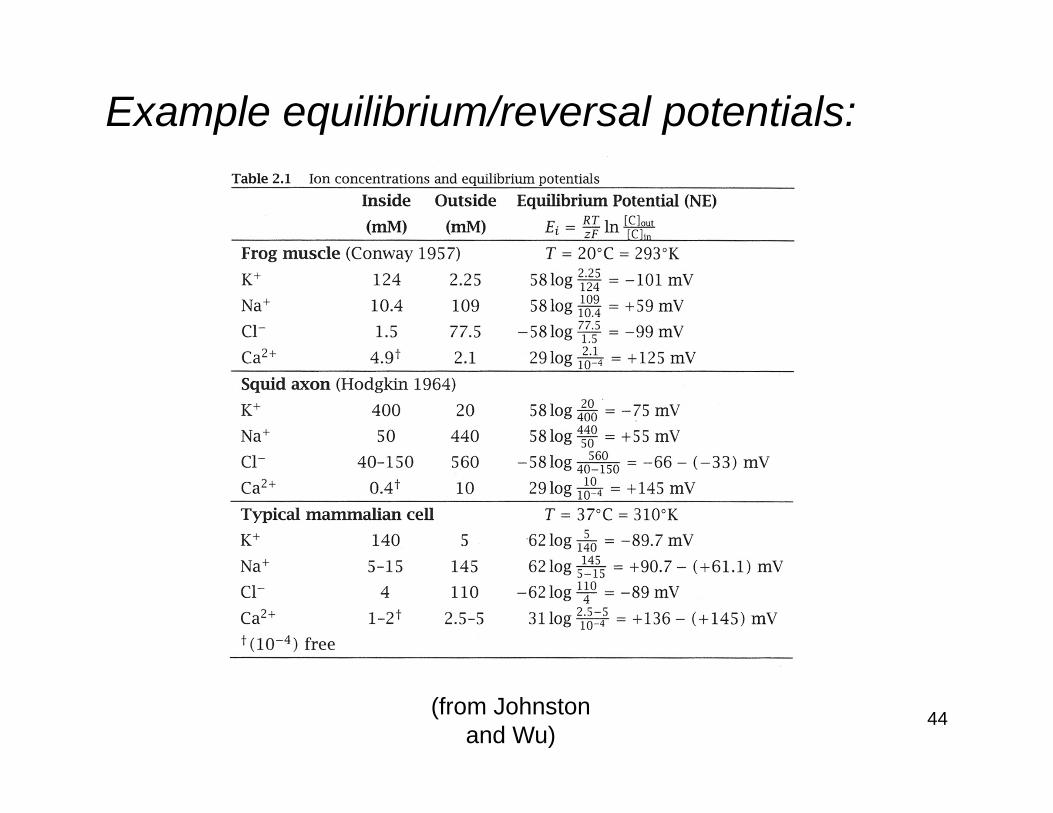
Example equilibrium/reversal potentials:
(from Johnstonand Wu)
45
Parallel conductance model:The two major results developed thus far are the Nernst-Planck equation and the Nernst potential.The latter utilizes the former to derive an expression for the equilibrium potential of each ion species.We would like to apply the Nernst-Planck equation to ion flow through a channel when it is not at the Nernst equilibrium. However, the exact concentration and electric potential gradients along the length of a channel are typically not known.
46
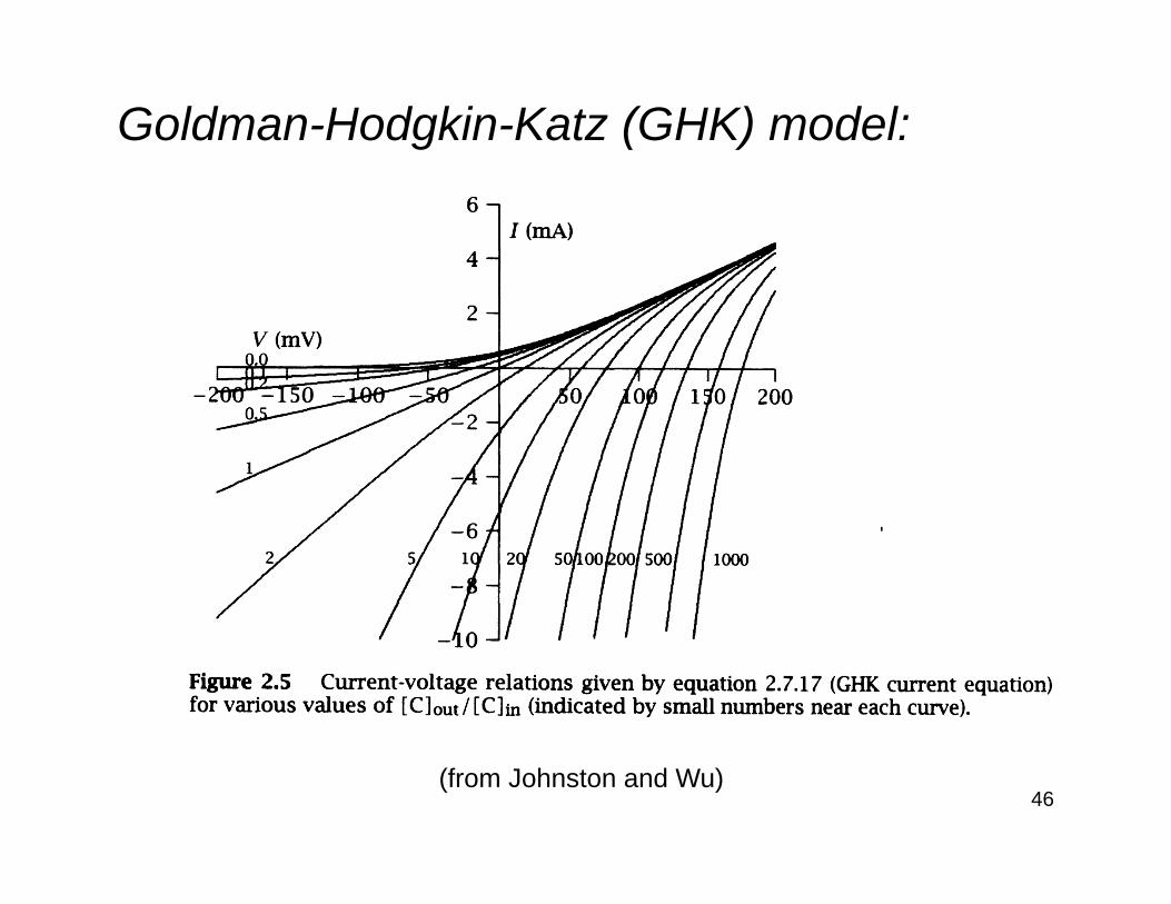
Goldman-Hodgkin-Katz (GHK) model:
(from Johnston and Wu)
47
Parallel conductance model (cont.):Unfortunately the GHK equations do notaccurately describe the behaviour of most ion channels.Consequently, a phenomenological description of current flow in ionic channels is typically used. This parallel conductance modeldoes incorporate three earlier results:1. the capacitance of the plasma membrane,2. the conductive nature of ion flow, and3. the equilibrium potential for each ion.
48
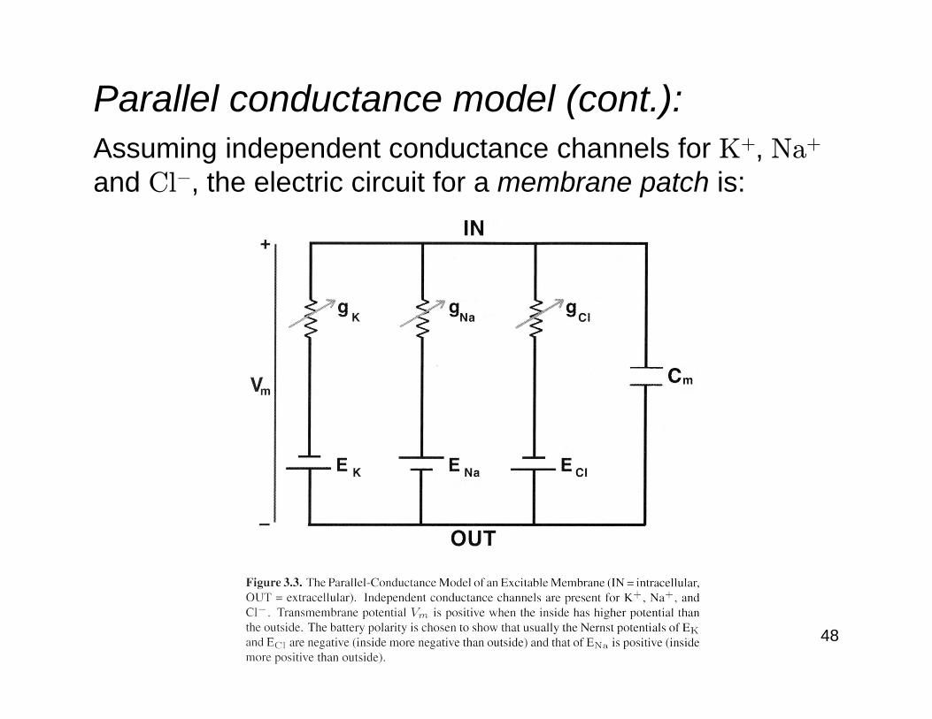
Parallel conductance model (cont.):Assuming independent conductance channels for K+, Na+
and Cl−, the electric circuit for a membrane patch is:
49
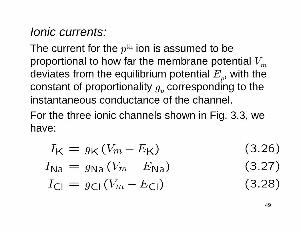
Ionic currents:The current for the pth ion is assumed to be proportional to how far the membrane potential Vm
deviates from the equilibrium potential Ep, with the constant of proportionality gp corresponding to the instantaneous conductance of the channel.For the three ionic channels shown in Fig. 3.3, we have:
50
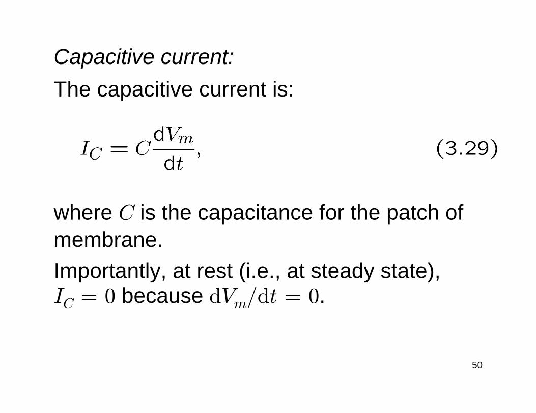
Capacitive current:The capacitive current is:
where C is the capacitance for the patch of membrane.Importantly, at rest (i.e., at steady state),IC = 0 because dVm/dt = 0.
51
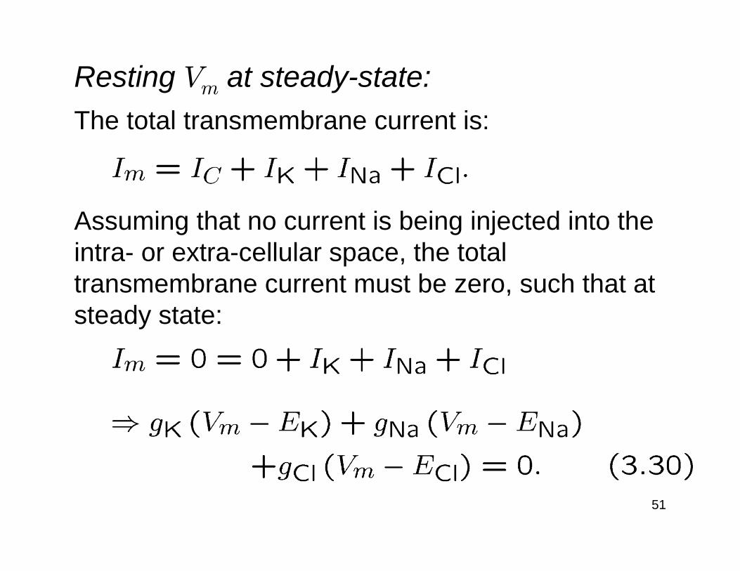
Resting Vm at steady-state:The total transmembrane current is:
Assuming that no current is being injected into the intra- or extra-cellular space, the total transmembrane current must be zero, such that at steady state:

52
Resting Vm at steady-state (cont.):Solving for Vm to obtain the resting transmembrane potential Vrest gives:
That is, the resting membrane potential is the weighted sum of the equilibrium potentials, where the weightings depend on the resting values of the ionic conductances.
53
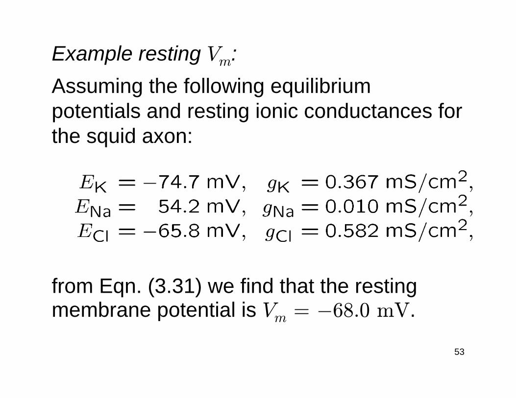
Example resting Vm:Assuming the following equilibrium potentials and resting ionic conductances for the squid axon:
from Eqn. (3.31) we find that the resting membrane potential is Vm = −68.0 mV.
54
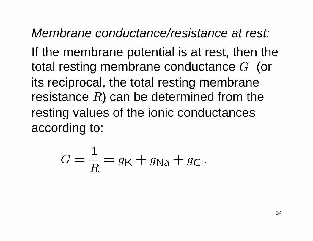
Membrane conductance/resistance at rest:If the membrane potential is at rest, then the total resting membrane conductance G (or its reciprocal, the total resting membrane resistance R) can be determined from the resting values of the ionic conductances according to:
55
Equivalent circuit near rest:
(from Koch)
56
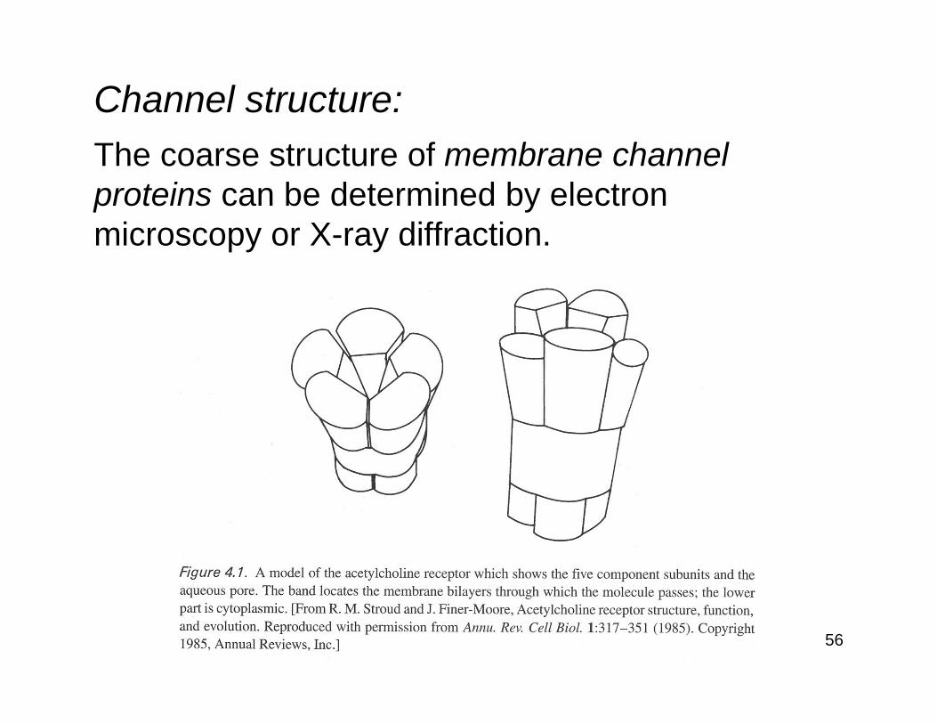
Channel structure:The coarse structure of membrane channel proteins can be determined by electron microscopy or X-ray diffraction.
57
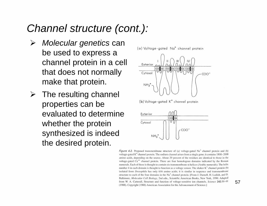
Channel structure (cont.):Molecular genetics canbe used to express achannel protein in a cellthat does not normallymake that protein.The resulting channel properties can beevaluated to determine whether the protein synthesized is indeedthe desired protein.
58
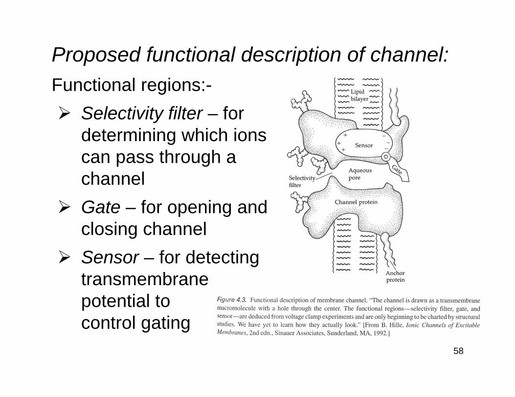
Proposed functional description of channel:Functional regions:-
Selectivity filter – fordetermining which ionscan pass through achannelGate – for opening andclosing channelSensor – for detectingtransmembranepotential tocontrol gating

59
Channel inactivation:In some channels, inactivation is thought to be achieved via a voltage-sensitive molecule that can block the channel opening.This is referred to as the “ball-and-chain” or “swinging gate” model.

60
Biophysical methods for measuring channel properties:Micropipette electrodes are used to measure ionic currents or transmembrane potentials.
61
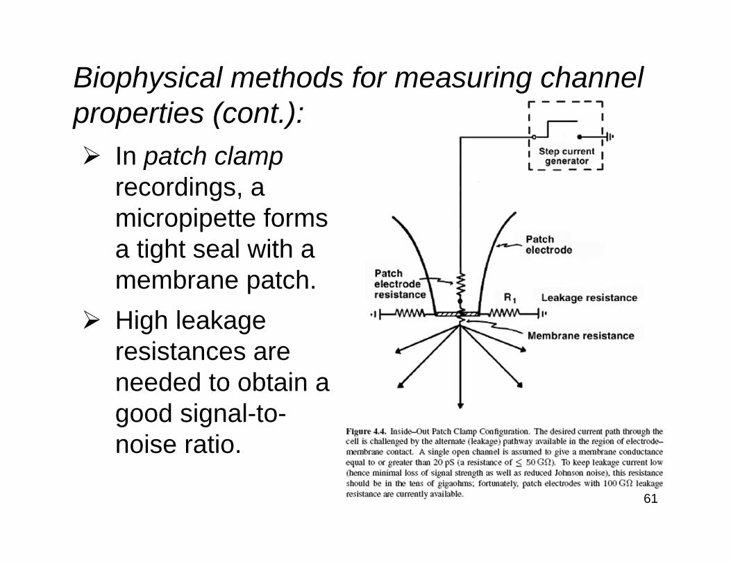
Biophysical methods for measuring channel properties (cont.):
In patch clamprecordings, amicropipette formsa tight seal with amembrane patch.High leakageresistances areneeded to obtain agood signal-to-noise ratio.
62
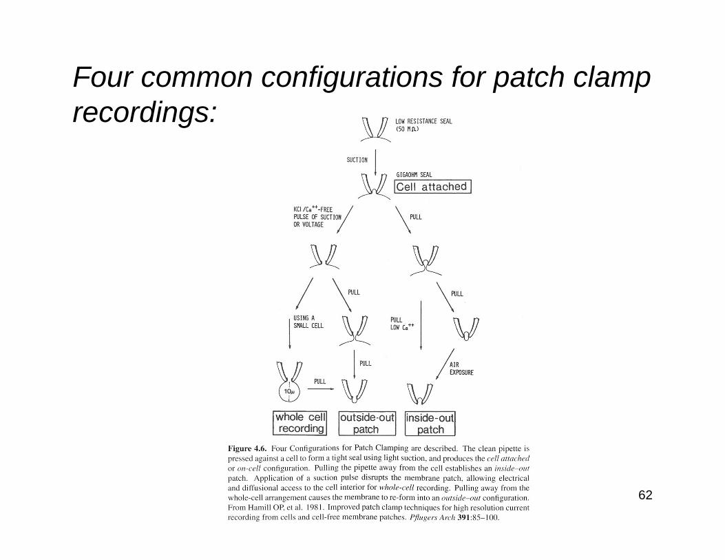
Four common configurations for patch clamp recordings:
63
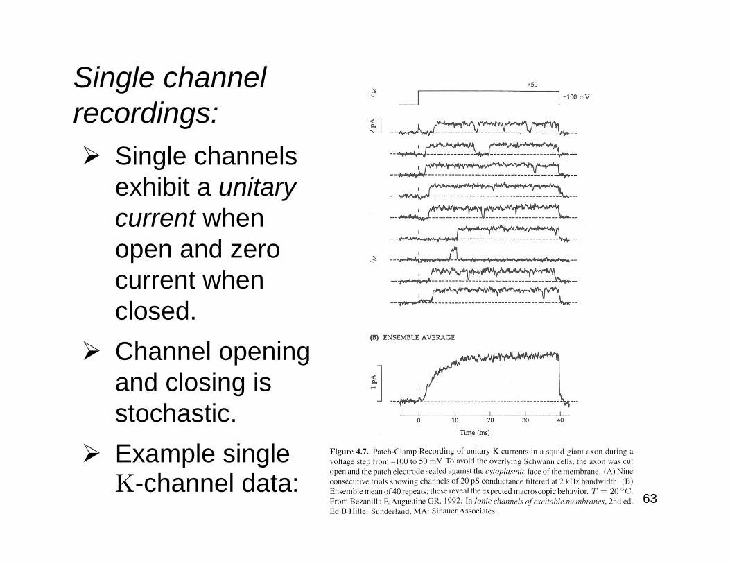
Single channel recordings:
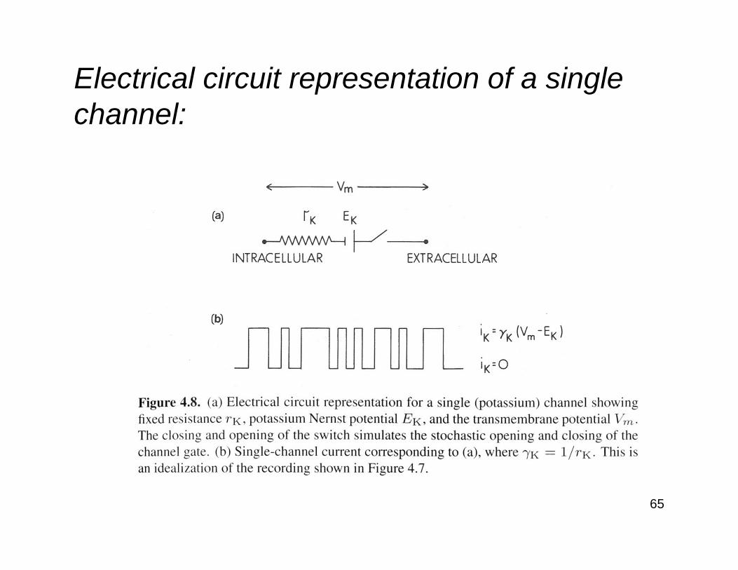
Single channels exhibit a unitary current when open and zero current when closed.Channel opening and closing is stochastic.Example single K-channel data:
64
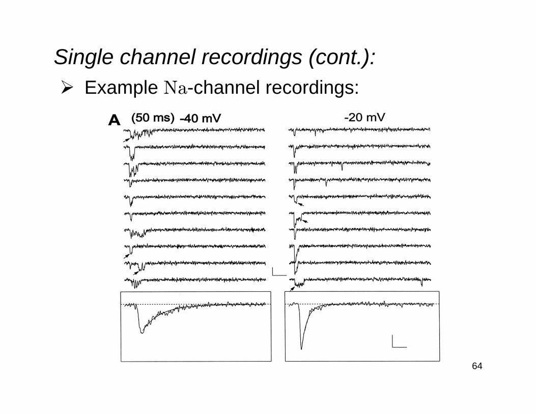
Single channel recordings (cont.):Example Na-channel recordings:
65
Electrical circuit representation of a single channel:
66
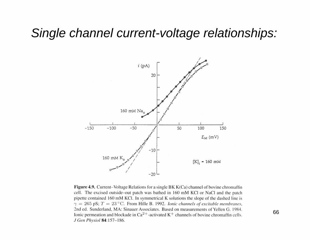
Single channel current-voltage relationships:

67
Single channel conductances and channel densities:
68
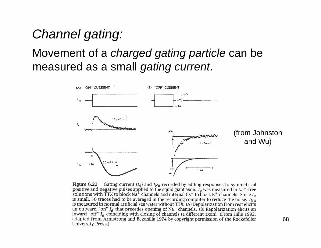
Channel gating:Movement of a charged gating particle can be measured as a small gating current.
(from Johnstonand Wu)

69
Channel gating (cont.):Structural model of open K-channel:
(Yarov-Yarovoy et al., PNAS 2006)
70
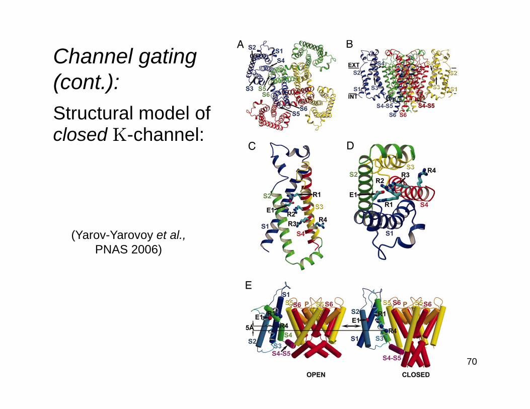
Channel gating(cont.):Structural model ofclosed K-channel:
(Yarov-Yarovoy et al.,PNAS 2006)