ECE322## Digital#Design#with#VHDL - Dept of …vvakilian/CourseECE322/LectureNotes/... ·...
29
ECE 322 Digital Design with VHDL Flip-flop and Registers Lecture 11
Transcript of ECE322## Digital#Design#with#VHDL - Dept of …vvakilian/CourseECE322/LectureNotes/... ·...

ECE 322 Digital Design with VHDL
Flip-flop and Registers
Lecture 11

California State University
Textbook References
n Sequential Logic ReviewStephen Brown and Zvonko Vranesic, Fundamentals of Digital Logic with VHDL Design, 2nd or 3rd Edition
Chapter 7 Flip-flop, Registers, Counters, and a Simple Processor
n In this lecture, we learn how to implement basic sequential blocks using VHDL
§ Latches§ Flip-flop§ Registers

California State University
n In a combinational circuit, the output depends only on the circuit’s inputs.
n In a sequential circuit, the output depends not only on the circuit’s inputs, but also on the values of a subset of the circuit’s nodes (which can include the output) which are fed back into the circuit.
This set of feedback node values is called the State (S)combinational sequential
Sequential Circuits
( )Y f X=( , )Y f X S=

California State University
Why are sequential circuits called sequential?
n It is because the circuit’s state depends on the input values from past times.
n This behavior causes a time sequence of output values to arise which depends on the time sequence of the input values.
Sequential Circuits

California State University
This circuit has two possible states:n A = 0 B = 1n A = 1 B = 0
A Simple Memory Element
A B
A simple memory element

California State University
Sequential Circuits-SR Latch
Consider a more complicated circuit – the SR latch – created by cross-coupling two NOR gates. (NAND gates could also be used).
The circuit state includes the signals Qa and Qb as these are the signals that are fed back into the circuit.
Qa
Qb
R
S

California State University
Sequential Circuits-SR Latch
S R Qa Qb
0 00 11 01 1
0/1 1/00 11 00 0
(a) Circuit (b) Truth table
Time
1
0
1
0
1
0
1
0
R
S
Q a
Q b
Qa
Qb
?
?
(c) Timing diagram
R
S
t1 t2 t3 t4 t5 t6 t7 t8 t9 t10
(no change)

California State University
Clock D 0 1 1
–0 1
0 1
Truth table Graphical symbol
t 1 t 2 t 3 t 4
Time
Clock
D
Q
Timing diagram
Q(t+1)Q(t)
D Q
Clock
Sequential Circuits-Gated D Latch

California State University
LIBRARY ieee ; USE ieee.std_logic_1164.all ;
ENTITY latch IS PORT ( D, Clock : IN STD_LOGIC ;
Q : OUT STD_LOGIC) ; END latch ;
ARCHITECTURE behavioral OF latch IS BEGIN
PROCESS ( D, Clock ) BEGIN
IF Clock = '1' THENQ <= D ;
END IF ; END PROCESS ;
END behavioral;
D Q
Clock
VHDL Code for Gated D Latch

California State University
Sequential Circuits
There are two main ways of synchronizing sequential circuits:§ Level-sensitive Clocking or Gating§ Edge-triggered Clocking
The level of a gate signal specifies whether the non-gate inputs to the circuit will affect the outputs. When the gate is at its active level, the inputs will be continually active.
In edge-triggered clocking, the inputs will only affect the outputs when the clock signal is transiting from low to high (or from high to low, or perhaps in both directions).

California State University
Master-Slave D Flip-Flop
One straightforward approach to creating an edge-triggered synchronous circuit is to combine two gated D latches, one after the other, with their gate signals inverted relative to each other.
This produces the so-called Master-Slave D Flip-Flop.

California State University
Master-Slave Flip-Flop
Gated D-latches

California State University
Clk D ↑↑
0 1
0 1
Truth table
t 1 t 2 t 3 t 4
Time
Clock
D
Q
Timing diagram
Q(t+1)
Q(t)
D Q
Clock
Graphical symbol
0 –Q(t)1 –
Positive-edge-triggered D Flip-Flop

California State University
LIBRARY ieee ; USE ieee.std_logic_1164.all ;
ENTITY flipflop IS PORT ( D, Clock : IN STD_LOGIC ;
Q : OUT STD_LOGIC) ; END flipflop ;
ARCHITECTURE behavioral OF flipflop IS BEGIN
PROCESS ( Clock ) BEGIN
IF Clock'EVENT AND Clock = '1' THEN Q <= D ;
END IF ; END PROCESS ;
END behavioral ;
D Q
Clock
VHDL Code for Positive-edge-triggered D Flip-Flop

California State University
LIBRARY ieee ; USE ieee.std_logic_1164.all ;
ENTITY flipflop IS PORT ( D, Clock : IN STD_LOGIC ;
Q : OUT STD_LOGIC) ; END flipflop ;
ARCHITECTURE behavioral2 OF flipflop IS BEGIN
PROCESS ( Clock ) BEGIN
IF rising_edge(Clock) THEN Q <= D ;
END IF ; END PROCESS ;
END behavioral2;
D Q
Clock
VHDL Code for Positive-edge-triggered D Flip-Flop

California State University
LIBRARY ieee ; USE ieee.std_logic_1164.all ;
ENTITY flipflop_ar IS PORT ( D, Resetn, Clock : IN STD_LOGIC ;
Q : OUT STD_LOGIC) ; END flipflop_ar ;
ARCHITECTURE behavioral OF flipflop_ar IS BEGIN
PROCESS ( Resetn, Clock ) BEGIN
IF Resetn = '0' THEN Q <= '0' ;
ELSIF rising_edge(Clock) THEN Q <= D ;
END IF ; END PROCESS ;
END behavioral ;
D Q
Clock Resetn
VHDL Code for a D Flip-Flop with Asynchronous Reset

California State University
LIBRARY ieee ; USE ieee.std_logic_1164.all ; ENTITY flipflop_sr IS
PORT ( D, Resetn, Clock : IN STD_LOGIC ; Q : OUT STD_LOGIC) ;
END flipflop_sr ;
ARCHITECTURE behavioral OF flipflop_sr IS BEGIN
PROCESS(Clock) BEGIN
IF rising_edge(Clock) THEN IF Resetn = '0' THEN
Q <= '0' ; ELSE
Q <= D ; END IF ;
END IF;END PROCESS ;
END behavioral ;
D Q
Clock Resetn
VHDL Code for a D Flip-Flop with Synchronous Reset
California State University
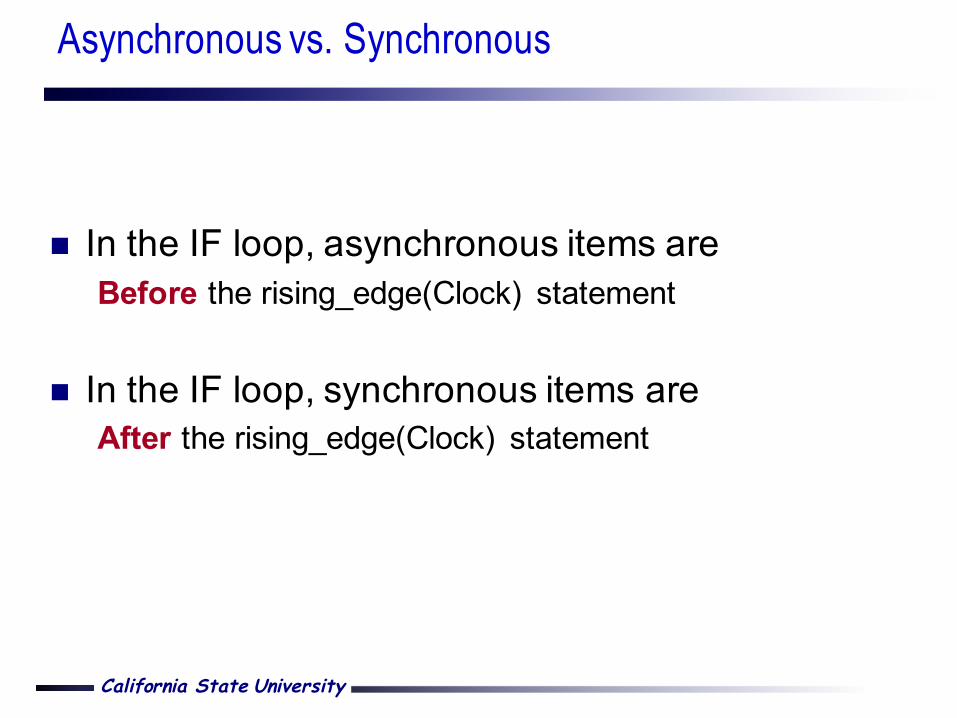
n In the IF loop, asynchronous items areBefore the rising_edge(Clock) statement
n In the IF loop, synchronous items areAfter the rising_edge(Clock) statement
Asynchronous vs. Synchronous

California State University
Different types of flip-flops can be constructed by adding circuitry to the basic D flip-flop.

California State University
T Flip-Flop
Clock
T
Q
(d) Timing diagram
T Q
Q
T
0 1
Q t 1 + ( )
Q t ( )
Q t ( )
(b) Truth table (c) Graphical symbol
D Q
Q
Q
Q T
Clock
(a) Circuit

California State University
J-K Flip-Flop
J Q K Q
J
D Q Q
K Q Q
Clock
(a) Circuit
J K Q (t +1)
0 0 Q ( t ) 0 1 0 1 0 1
1 1 Q (t )
(b) Truth table (c) Graphical symbol

California State University
Registers

California State University
Register
§ A flip-flop stores one bit of information. When a set of n flip-flops is used to store n bits of information, we refer to these flip-flops as a register.
§ A common clock is used for each flip-flop in a register

California State University
Shift Register
D Q
Q Clk
D Q
Q
D Q
Q
D Q
Q
In Out
t 0
t 1
t 2
t 3
t 4
t 5
t 6
t 7
1 0 1 1 1 0 0 0
0 1 0 1 1 1 0 0
0 0 1 0 1 1 1 0
0 0 0 1 0 1 1 1
0 0 0 0 1 0 1 1
Q 1 Q 2 Q 3 Q 4 Out = In
(b) A sample sequence
(a) Circuit
Q 1 Q 2 Q 3 Q 4
SHIFTREGISTER
In
ClkOut
California State University
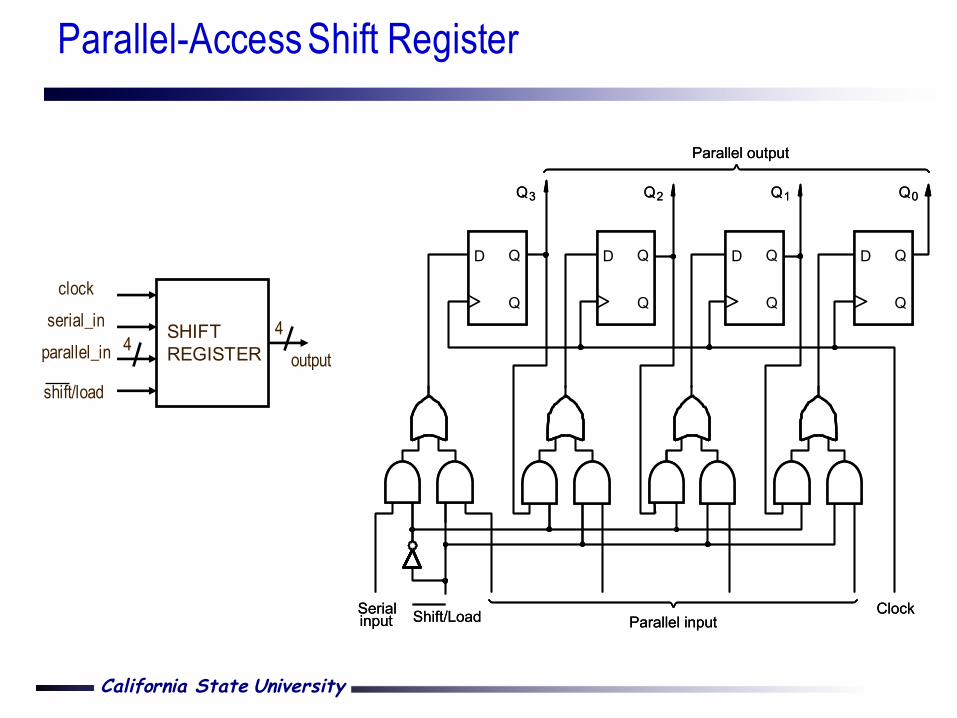
Parallel-Access Shift Register
Q3 Q2 Q1 Q0
ClockParallel input
Parallel output
Shift/LoadSerialinput
D Q
Q
D Q
Q
D Q
Q
D Q
Q
Q3 Q2 Q1 Q0
ClockParallel input
Parallel output
Shift/LoadSerialinput
D Q
Q
D Q
Q
D Q
Q
D Q
Q
SHIFTREGISTER
serial_inclock
parallel_in 4
shift/loadoutput
4

California State University
LIBRARY ieee ;USE ieee.std_logic_1164.all ;
ENTITY reg8 ISPORT ( D : IN STD_LOGIC_VECTOR(7 DOWNTO 0) ;
Resetn, Clock : IN STD_LOGIC ;Q : OUT STD_LOGIC_VECTOR(7 DOWNTO 0) ) ;
END reg8 ;
ARCHITECTURE behavioral OF reg8 ISBEGIN
PROCESS ( Resetn, Clock )BEGIN
IF Resetn = '0' THENQ <= "00000000" ;
ELSIF rising_edge(Clock) THENQ <= D ;
END IF ;END PROCESS ;
END behavioral ;`
Resetn
Clock
reg8
8 8
D Q
VHDL Code for a 8-Bit Register with Asynchronous Clear

California State University
n Generics allow a design entity to be described so that, for each use of that component, Its structure and behavior can be changed by generic values. In general they are used to construct parameterized hardware components.
n Generics are typically integer valuesØ In this class, the entity inputs and outputs should be std_logic or std_logic_vectorØ But the generics can be integer
n Generics are given a default valueØ GENERIC ( N : INTEGER := 16 ) ;Ø This value can be overwritten when entity is instantiated as a component
n Generics are very useful when instantiating an often-used componentØ Need a 32-bit register in one place, and 16-bit register in anotherØ Can use the same generic code, just configure them differently
Use of GENERIC in VHDL

California State University
OTHERS stand for any index value that has not been previously mentioned.
Q <= “00000001” can be written as Q <= (0 => ‘1’, OTHERS => ‘0’)
Q <= “10000001” can be written as Q <= (7 => ‘1’, 0 => ‘1’, OTHERS => ‘0’)or Q <= (7 | 0 => ‘1’, OTHERS => ‘0’)
Q <= “00011110” can be written as Q <= (4 downto 1=> ‘1’, OTHERS => ‘0’)
Use of OTHERS in VHDL

California State University
LIBRARY ieee ;USE ieee.std_logic_1164.all ;
ENTITY regn ISGENERIC ( N : INTEGER := 16 ) ;PORT ( D : IN STD_LOGIC_VECTOR(N-1 DOWNTO 0) ;
Resetn, Clock : IN STD_LOGIC ;Q : OUT STD_LOGIC_VECTOR(N-1 DOWNTO 0) ) ;
END regn ;
ARCHITECTURE behavioral OF regn ISBEGIN
PROCESS ( Resetn, Clock )BEGIN
IF Resetn = '0' THENQ <= (OTHERS => '0') ;
ELSIF rising_edge(Clock) THENQ <= D ;
END IF ;END PROCESS ;
END behavioral ;
Resetn
Clock
regn
N N
D Q
VHDL Code for a N-Bit Register with Asynchronous Clear