ECE110 Introduction to Electronics
125
8/19/2016 ECE110 Introduction to Electronics What is…? • ECE • ECE110 • Charge • Current • Voltage • Energy • Power 1 Defining our field of study “Engineers use the knowledge of mathematics and natural sciences gained by study, experience, and practice, applied with judgment, to develop ways to economically utilize the materials and forces of nature for the benefit of mankind. “ - ABET (Accreditation Board for Engineering and Technology) Electrical engineering (EE) is a field of engineering that generally deals with the study and application of electricity, electronics, and electromagnetism - WikiPedia 2
Transcript of ECE110 Introduction to Electronics

8/19/2016
ECE110 Introduction to Electronics
What is…?
• ECE
• ECE110
• Charge
• Current
• Voltage
• Energy
• Power
1
Defining our field of study
“Engineers use the knowledge of mathematics and natural sciences gained by study, experience, and practice, applied with judgment, to develop ways to economically utilize the materials and forces of nature for the benefit of mankind. “
- ABET (Accreditation Board for Engineering and Technology)
Electrical engineering (EE) is a field of engineeringthat generally deals with the study and application of electricity, electronics, and electromagnetism
- WikiPedia2
8/19/2016
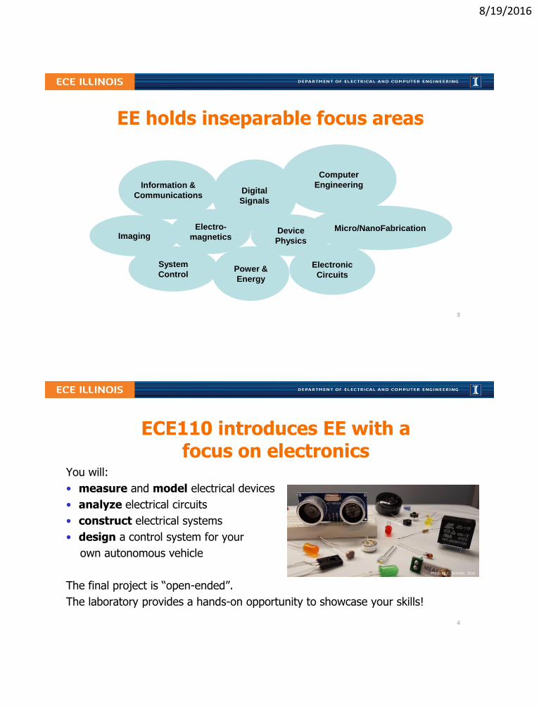
EE holds inseparable focus areas
Electronic
Circuits
System
Control
Digital
Signals
Electro-
magneticsMicro/NanoFabrication
Imaging
Information &
Communications
Power &
Energy
Computer
Engineering
Device
Physics
3
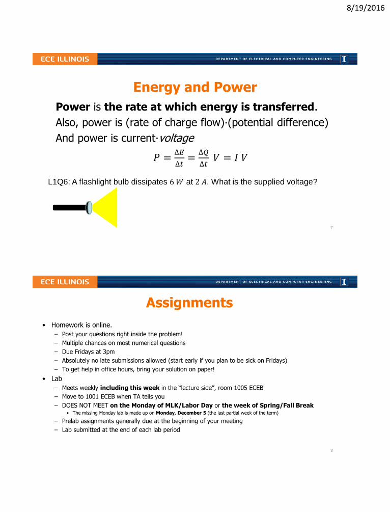
ECE110 introduces EE with a focus on electronics
You will:
• measure and model electrical devices
• analyze electrical circuits
• construct electrical systems
• design a control system for your
own autonomous vehicle
The final project is “open-ended”.
The laboratory provides a hands-on opportunity to showcase your skills!
Photo by C. Schmitz, 2016
4

8/19/2016
Charge and Current
• an electron is a charged subatomic particle
• the coulomb (C) is a measure of electric charge with
−1.6 × 10⁻¹⁹𝐶
𝑒𝑙𝑒𝑐𝑡𝑟𝑜𝑛(𝑛𝑜𝑡𝑎𝑡𝑖𝑜𝑛)=
−1.6 e − 19 𝐶
𝑒𝑙𝑒𝑐𝑡𝑟𝑜𝑛
• Electric current is the flow of electric charge in time (𝐶/𝑠)
𝐼 = Δ𝑄/Δ𝑡
• The ampere is the unit of electric current
1 𝐴 = 1 𝐶/𝑠
L1Q1: What is the charge of 1 billion electrons?
L1Q2: A “typical” electronics circuit might have 1 billion electrons pass a cross section of a wire
every nanosecond, what is the electric current in amps?
Q2 Answers:
A. 0.00000016 A
B. 0.0001 A
C. 1 A
D. 1e-9 A
E. 160e-12 A
Image is public domain.
5
Voltage and Energy
• Energy is the ability to do work, measured in joules (𝐽), BTUs, calories, kWh, mAh, etc.
• Voltage is the work done per unit charge (eg. 𝐽/𝐶) against a static electric field to move charge between two points
• Also, 1 volt (1 𝑉) is the electric potential difference between two points that will impart 1 𝐽 of energy per coulomb (1 𝐶) of charge that passes through it.
Δ𝐸 = Δ𝑄 × 𝑉
L1Q3: A certain battery imparts 480 pJ to every 1 billion electrons. What is its voltage?
L1Q4: What is the charge moved through 400 V (EV battery) to provide 800 kJ of energy?
L1Q5: What is the average current if the energy in Q4 is provided in five seconds?6
8/19/2016
Energy and Power
Power is the rate at which energy is transferred.
Also, power is (rate of charge flow)∙(potential difference)
And power is current∙voltage
𝑃 =∆𝐸
∆𝑡=∆𝑄
∆𝑡𝑉 = 𝐼 𝑉
L1Q6: A flashlight bulb dissipates 6𝑊 at 2 𝐴. What is the supplied voltage?
7
Assignments
• Homework is online.
– Post your questions right inside the problem!
– Multiple chances on most numerical questions
– Due Fridays at 3pm
– Absolutely no late submissions allowed (start early if you plan to be sick on Fridays)
– To get help in office hours, bring your solution on paper!
• Lab
– Meets weekly including this week in the “lecture side”, room 1005 ECEB
– Move to 1001 ECEB when TA tells you
– DOES NOT MEET on the Monday of MLK/Labor Day or the week of Spring/Fall Break• The missing Monday lab is made up on Monday, December 5 (the last partial week of the term)
– Prelab assignments generally due at the beginning of your meeting
– Lab submitted at the end of each lab period
8

8/19/2016
Attendance policies
• Lab attendance
– Mandatory
– medical or personal emergency?
Contact your lab Teaching Assistant (not me!) ASAP
– No food/drink in 1001 ECEB (but okay in 1005 ECEB)
• Lecture attendance
– Attend 4 out of every 5 lectures, on average, and you mightget a perfect attendance score. It is collected via unannounced i>clicker quizzes during most lectures. You may attend ANY lecture section to gain attendance credit for that day.
9
Grading policies
*You must score at least 50% in each of lecture and lab grades to avoid failing!
Laboratory 30%
Weekly Labs 15%
Explore More! Modules 5 %
Final Project 10%
Lecture Total 70%
3 midterms 30%
Final Exam 25%
Homework 10%
Attendance 5 %
10

8/19/2016
Required course materials
• IUB Bookstore
– ECE 110 Lecture Slides (also online)
– Lab Procedures (also online)
• ECE Supply Center
– ECE110 Electronics
– Arduino (or RedBoard)
– i>clicker
• Online (courses.engr.Illinois.edu/ece110)
– Announcements
– Course notes, examples, videos, etc.
– Weekly assignments11
L1 Learning Objectives
a. (L1a) Compute relationships between charge, time, and current.
b. (L1b) Compute relationships between charge, voltage, and energy.
c. (L1c) Compute relationships between power, current, and voltage.
𝐼 =Δ𝑄
Δ𝑡
𝑃 =∆𝐸
∆𝑡=∆𝑄
∆𝑡𝑉 = 𝐼 𝑉
Δ𝐸 = Δ𝑄 × 𝑉
𝑉 =ΔE
Δ𝑄
12
8/19/2016
Lecture 2: A history…From Charge Storage to Ohm’s Law
• A short video
• Capacitors
• Batteries
• Conservation of Energy
• Ohm’s Law
13
Energy Facts
• Conservation of Energy
𝐸𝑖𝑛𝑝𝑢𝑡 = 𝐸𝑢𝑠𝑒𝑓𝑢𝑙 + 𝐸𝑤𝑎𝑠𝑡𝑒
• Mechanical Energy
Kinetic and Potential Energy; Energy vs. Power
• Electrical Energy Storage
Capacitors and Batteries
14
8/19/2016
Capacitors: store electrical energy
• 𝐶 = 𝑄/𝑉 – capacitance is the charge-to-voltage ratio of a capacitor
𝐸𝑐𝑎𝑝𝑎𝑐𝑖𝑡𝑜𝑟 =1
2𝐶𝑉2
• The first device for storing electrical energy became known as Leyden Jar after the city in which it was built (1745). It had a capacitance of about 1 𝑛𝐹.
L2Q1: At what voltage would a 1 𝑛𝐹 capacitor have the energy to lift 100 𝑘𝑔 by 2 𝑐𝑚?
In History…
Yes, Benjamin Franklin collected
electrostatic charge from a storm
using a kite in 1752, but also
formulated the principle of
conservation of electric charge and
coined the
terms “positive”
and “negative”
with respect to
the charge
carriers.
15
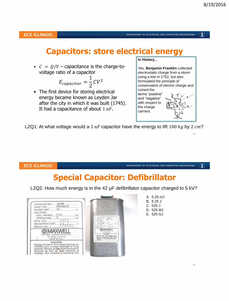
L2Q2: How much energy is in the 42 µF defibrillator capacitor charged to 5 kV?
Special Capacitor: Defibrillator
A. 5.25 mJ
B. 5.25 J
C. 525 J
D. 525 MJ
E. 525 GJ
16
8/19/2016
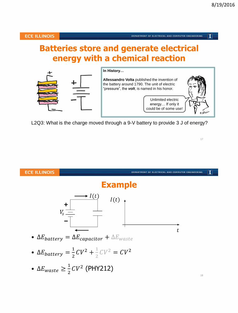
In History…
Allessandro Volta published the invention of
the battery around 1790. The unit of electric
“pressure”, the volt, is named in his honor.
Batteries store and generate electrical energy with a chemical reaction
Unlimited electric
energy… If only it
could be of some use!
L2Q3: What is the charge moved through a 9-V battery to provide 3 J of energy?
17
Example
• Δ𝐸𝑏𝑎𝑡𝑡𝑒𝑟𝑦 = Δ𝐸𝑐𝑎𝑝𝑎𝑐𝑖𝑡𝑜𝑟 + Δ𝐸𝑤𝑎𝑠𝑡𝑒
• Δ𝐸𝑏𝑎𝑡𝑡𝑒𝑟𝑦 =1
2𝐶𝑉2 +
1
2𝐶𝑉2 = 𝐶𝑉2
• Δ𝐸𝑤𝑎𝑠𝑡𝑒 ≥1
2𝐶𝑉2 (PHY212)
18

8/19/2016
Batteries and capacitors notes
• The current drawn from a capacitor or battery depends on the load.
– Include wires, light bulbs, LEDs, motors, etc.
– What limits the maximum current possible?
– We need simplified Models for batteries and loads
• Batteries vs. Capacitors
L2Q4: If a battery is labeled at 9 V and 500 mAh, how much energy does it store?
L2Q5: For how long can such battery power an LED if it draws 50 mA of current?
19
Ohm’s law models the current and voltage relationship in conductors
Motivated by long-distance telegraphy, Georg Ohm (~1825) conducted careful experimentation to find this widely-used approximate mathematical model:
𝐼 =𝑉
𝑅
where 𝑅 = 𝜌𝑙
𝐴is resistance of a conductor (e.g. wire)
with length, 𝑙, and area 𝐴, and where 𝜌 is resistivity - a material parameter
L2Q6: Find the diameter of one mile of Cu (𝜌 = 1.7 × 10⁻⁸ Ω𝑚) wire when 𝑅 = 10 Ω.
L2Q7: If the resistance of one wire is 10 Ω, what is the resistance of two such wires in parallel?
20

8/19/2016
Resistors are devices that obey Ohm’s Law • Resistors are used to set current when voltage is given
• Resistors are used to set voltage when current is given
• Power is always dissipated in resistors, and they heat up
𝑃 = 𝐼 𝑉 =𝑉2
𝑅= 𝐼2𝑅
L2Q8: If a resistor of 100 Ω is rated at 0.25 W, what is its maximum current?
L2Q9: What is the power dissipated by that resistor if there is a 6 V drop across it?
In History…
Henry Cavendish conducted
similar experiments over 40
years earlier than Georg Ohm
using Leyden jars for voltage
sources and the shock felt by
his body as an ad hoc ammeter!
21
Resistances are used to model devices
• Lengths of wire
• Incandescent bulbs
• Heating elements
• Battery terminals
• Stalled motors
• Fuses, etc.
L2Q10: If a 9 V battery has a maximum current of 2 A, what is its model contact R?
models
22
8/19/2016
Q11: When would you want to use a capacitor over a battery?
A. When you need a burst of high current for short time
B. When you need to power something at a constant current over a long period of time
C. Always, batteries just too expensive compared to caps
D. Never, batteries are better, more expensive than caps
E. I’m not sure what’s going on
23
L2 Learning Objectives
a. (L2a) Solve energy transfer problems involving mechanical potential and kinetic energy as well as efficiency (or wasted energy) considerations.
b. (L2b) Compute power, energy, and time, given two of three.
c. (L2c) For a capacitor, compute stored energy, voltage, charge, and capacitance given any of the two quantities.
d. (L2d) Compute energy stored in a battery and discharge time.
e. (L2e) Compute resistance of a cylindrical conductor given dimensions.
f. (L2f) Relate voltage and current for an “Ohmic” conductor.
g. (L2g) Perform unit conversions for energy, charge, etc.
h. (L2h) Use Ohm’s Law to model the internal resistance of a physical battery.
24

8/19/2016
Lecture 3 : Power and Energy
• Announcements
• Avoidance of Ethical Issues
• Power and Energy with examples
25
There Should Always be Alignment in a Community
26

8/19/2016
Proactively avoid ethical dilemmas Picking Up the Slack…search at Santa Clara University:
http://www.scu.edu/
Often called a “hitch-hiker” scenario…
What do you feel Greg should do?
A. Value the relationship, grade Natalie the same as the group.
B. Greg is not a babysitter…give Natalie the grade she earned.
C. Give Natalie a worse grade than the group, but better than she deserved.
D. Talk to Natalie before deciding which grade to give.
E. Talk to the Instructor before deciding which grade to give.
What would you have done?
27
Recall “Energy”
• Energy is ability to do work
• Energy comes in many forms
• Energy is conserved (can change forms)
Examples: heat, light, electrical energy, chemical, mechanical (e.g. potential, kinetic), mass, etc…
28

8/19/2016
What is “work” ?
• drive to Chicago
• move a couch
• cook an egg
• lift a camel
• launch a satellite
• stay awake in lecture (try!)
• electrocute somebody (don’t!)
• send an email (to Brazil or Urbana?)
• write down some of your own ideas
29
Driving to Chicago…accounting
If 𝚫𝐄𝐬𝐭𝐚𝐭𝐞 ≡ 𝑬𝒖𝒔𝒆𝒇𝒖𝒍, then
𝑬𝒊𝒏𝒑𝒖𝒕 = 𝜟𝑬𝒔𝒕𝒂𝒕𝒆+ 𝑬𝒘𝒂𝒔𝒕𝒆Don’t waste
energy - use
Hyperloop!
• Distance: 200 km
• Elevation Drop: 44 m
• Where is the waste?
L3Q1: How much energy does it take to accelerate a 2200 kg car from 0 to 60 mph?
L3Q2: What is the energy input needed if the engine/drive train losses are 70%?
L3Q3: A certain gas car gets 50 km/gal (ave). How much energy does it take to get to Chicago?
= 𝜂𝐸𝑖𝑛𝑝𝑢𝑡 + 1− 𝜂 𝐸𝑖𝑛𝑝𝑢𝑡
Q1:
A. 8 mJ
B. 1 J
C. 80 J
D. 1 kJ
E. 800 kJ
30

8/19/2016
Rate of lifting camels – power!
Definition of power: 𝑃 =∆𝐸
∆𝑡is rate of energy…
L3Q4: What is the average power needed to lift 500 kg by two meters every minute?
L3Q5: What is the power needed to expend 800 kJ in five seconds?
L3Q6: What is the charge moved through 400 V to provide 800 kJ of energy?
L3Q7: What is the average current if the energy in Q5 is provided in five seconds?31
L3 Learning Objectives
a. (L3a) Develop a plan to avoid an ethical dilemma in the laboratory
b. (L3b) Solve energy transfer problems involving mechanical potential and kinetic energy as well as efficiency (or wasted energy) considerations.
c. (L3c) Compute power, energy, and time, given two of three.
32

8/19/2016
What to do if you are Feeling Ill…
Sick? Don’t come to class and risk infecting others. Instead, notify your instructor or TA as soon as possible via email of your condition.
For lecture, this will be counted towards your 20% excused absences.
For lab, one or two absences will typically be allowed makeup at the discretion of your head TA.
33
More learning opportunities
• Optional Discussion and Practice: Friday workshops (TBD, as announced)
• Office Hours: Room 1005 (near lab)
• Center for Academic Resources in Engineering (CARE, Grainger Library)
• Honors section: targeting James Scholars
Encountering various difficulties? Contact your Instructor, lab TA, or the advising office on the second floor (2120 ECEB)!
34

8/19/2016
Seeking advice and help
• Talk to Instructors and Teaching Assistants
• Center for Academic Resources in Engineering (CARE) for tutoring options in
STEM courses.
• ECE Department Advising Office (2120 ECEB) for academic advice. They can also recommend others:
– U of I Counseling Center for time management, study skill, test-taking skills, and confidential personal counseling
– Disability Resources & Educational Services
35
Other policies
• We expect you to conduct yourselves in accordance with the University’s Student Codehttp://admin.illinois.edu/policy/code/
• We absolutely welcome your suggestions to make this course—your course—better!!
• These slides contain only an overview of the syllabus. Read the syllabus handout in its entirety. It contains information useful for your first homework.
36

8/19/2016
Lecture 4: Circuit Modelling and Schematics
• Circuit Modeling and Schematics: A resistive heater
• Electromagnetism – Oersted’s 1820 demonstration
• Measuring current and moving things that are near and far
• Long-distance telegraphy; Ohm’s law
• Circuits: graphical representations and mathematical models
• Model and solve very simple (one loop) circuits
• Network Examples: Broadcast Telegraphy, Decorative Lights
37
Circuit model for car window defroster
L4Q1: What is the resistance of the car window defroster if it dissipates 60 W?
(Consider that the car battery has a max current of 600 A)
rear window heater
switch
What percentage of available
battery current is sent to the
rear window heater?
A. 1%
B. 10%
C. 50%
D. 75%
E. 95%
38

8/19/2016
Electric current deflects a compass needle
In History…
Hans Christian Oersted’s
observation of this effect in 1820
surprised him during his lecture
demonstration to advanced
students. Detailed experiments
followed
later.
Image in Public Domain
39
Galvanometer measures current
• Each wire in a coil adds to magnetic field, B
• Wires segments on all sides add to B
• Counteracts Earth’s magnetic field
• More current – bigger angle of needle
• More sophisticated galvanometers came later
• Ampere (A), becomes a fundamental unit
• I is for Intensité (Intensity in French)
Image from book: Electrical Measurement
and the Galvanometer: Its Construction and Uses,
by T. D. Lockwood, New York: J. H. Bunnell and Co., 1890
Image in Public Domain.
40

8/19/2016
A coil with current acts as a magnet
Relay principle: 1. Coil, 2. Armature, 3. Moving contact
Source: Wikimedia Commons
L4Q2: For how long can Energizer 522 (~500 mAh) 9 V
battery operate a relay (JQX-15F) which draws 100 mA?
Q2 answers:
A. About 1.5 hours
B. About 3 hours
C. About 5 hours
D. About 9 hours
E. About 45 hours
41
Circuit Model For a Telegraph Loop
L4Q3: If a 9 V battery with 4 Ω contact resistance is used and the relay has 80 Ω
and the wire has 10 Ω/mile, what is the maximum telegraph distance which will
result in a 50 mA current through the relay circuit loop?
relay
(sometimes replaced by earth)
battery
42

8/19/2016
Broadcasting: multiple ways to wire relays
A.
B.
C.
i>clicker:
Which method (A, B, or C) is a
Parallel combination of towns?
43
Decorative lights: multiple ways to connect bulbs to the wall power plug
L4Q4: Draw a circuit for 12 lightbulbs connected in series in one loop.
L4Q5: Draw a circuit for 12 lightbulbs connected in two parallel branches.44

8/19/2016
L4 Learning Objectives
a. Draw one-loop circuit schematics to model simple setups
b. Draw source and resistor circuits to model real-world problems
45
Lecture 5: Kirchhoff's Laws in Circuits
• Kirchhoff’s Current Law (KCL) – Conservation of Charge
• Kirchhoff’s Voltage Law (KVL) – Conservation of Energy
• Solving Circuits with KCL, KVL, and Ohm’s Law
• Power Conservation in Circuits
46

8/19/2016
Kirchhoff’s Current Law
Current in = Current out
Conservation of charge!
(What goes in must come out, or…
…the total coming in is zero)Image source: MONGABAY.COM
47
KCL equations are often used at nodes, but can also be used for a sub-circuit
A. 𝐼1 = 𝐼2 + 𝐼4B. 𝐼4 = 𝐼5 + 𝐼6C. 𝐼1 + 𝐼3 = 𝐼6D. 𝐼3 + 𝐼5 = 𝐼2E. 𝐼6 − 𝐼4 = 𝐼3 + 𝐼2
L5Q1: Which of the equations is NOT a correct application of KCL?
48

8/19/2016
Kirchhoff’s Voltage Law
The sum of all voltages around any closed path (loop) in a circuit equals zero
Conservation of Energy!
With voltage, what goes up, must come down
49
KVL and Elevation Analogy
One can add up elevation changes as we go in a loop from city to city.
The result should be zero, independent of the path taken.
Free Picture: Stairs To The Sky ID: 191634
© Jennifer Harvey | Dreamstime Stock Photos
50

8/19/2016
Keeping track of voltage drop polarity is important in writing correct KVL equations.
L5Q2: Which of the equations is NOT a correct application of KVL?
A. 𝑉1 − 𝑉2 − 𝑉3 = 0B. 𝑉1 = 𝑉2 + 𝑉5 + 𝑉6C. 𝑉1 − 𝑉4 = 𝑉6D. 𝑉3 + 𝑉2 = 𝑉1E. 𝑉3 + 𝑉5 = 𝑉6
51
Missing voltages can be obtained using KVL.
L5Q3: What are the values of the voltages 𝑉1, 𝑉2 and 𝑉6 if 𝑉3 = 2 𝑉, 𝑉4 = 6 𝑉, 𝑉5 = 1 𝑉?
In History…
The conceptual theories of
electricity held by Georg Ohm
were generalized in Gustav
Kirchhoff’s laws (1845). Later,
James Clerk Maxwell’s
equations (1861) generalized the
work done by Kirchhoff, Ampere,
Faraday, and others.
52

8/19/2016
Circuits are solved with Ohm’s + KCL + KVL
L5Q4: What is the value of the source voltage?
L5Q5: How much power is the source supplying?
L5Q6: How much power is each resistance consuming? 53
L5 Learning Objectives
a. Identify and label circuit nodes; identify circuit loops
b. Write node equation for currents based on KCL
c. Write loop equations for voltages based on KVL
d. Solve simple circuits with KCL, KVL, and Ohm’s Law
e. Calculate power in circuit elements, verify conservation
54

8/19/2016
Lecture 6: Current and Voltage Dividers
• Series Connections, Equivalent Resistance, Voltage Divider
• Parallel Connections, Equivalent Resistance, Current Divider
• Power Dissipation in Series and Parallel Resistive Loads
• Example Problems and Practice
55
Series Connection
Series connections share the same current
𝐼1 = 𝐼2 = 𝐼3 because of KCL56

8/19/2016
Equivalent Resistance of Series Resistors
Resistances in series add up
𝑅𝑒𝑞 = 𝑅1 + 𝑅2 +⋯+ 𝑅𝑁
This can be intuitive: think of telegraphy wires in series.
=
57
Voltage Divider Rule (VDR)
When a voltage divides across resistors in series, more voltage drop appears across the largest resistor.
𝑉𝑘 =𝑅𝑘𝑅𝑒𝑞⋅ 𝑉
L6Q1: Can a voltage across one of the resistors be higher than the total V?
58

8/19/2016
If 𝑅1 < 𝑅2, which of the following is true?
A. 𝑉1 < 𝑉2 and 𝐼1 < 𝐼2B. 𝑉1 < 𝑉2 and 𝐼1 = 𝐼2C. 𝑉1 = 𝑉2 and 𝐼1 = 𝐼2D. 𝑉1 > 𝑉2 and 𝐼1 = 𝐼2E. 𝑉1 > 𝑉2 and 𝐼1 > 𝐼2
+𝑉1−
+𝑉2−
59
VDR Derivation
Since 𝐼 = 𝐼𝑘,𝑉
𝑅𝑒𝑞=𝑉𝑘
𝑅𝑘by Ohm’s Law. So, 𝑉𝑘 =
𝑅𝑘
𝑅𝑒𝑞⋅ 𝑉
=
60

8/19/2016
Parallel Connection
Parallel connections share the same voltage potentials at two end nodes (shared by the elements)
𝑉1 = 𝑉2 = 𝑉3 because of KVL
L6Q2: Are appliances in your house/apartment connected in series or in parallel? 61
Equivalent Resistance of Parallel Resistors
1
𝑅𝑒𝑞=1
𝑅1+1
𝑅2+⋯+
1
𝑅𝑁
If 𝑁 = 2, 𝑅𝑒𝑞 =𝑅1𝑅2
𝑅1+𝑅2
Adding resistance in parallel always brings resistance down!This can be intuitive: think of combining wire strands to make a thicker wire.
=
62
8/19/2016
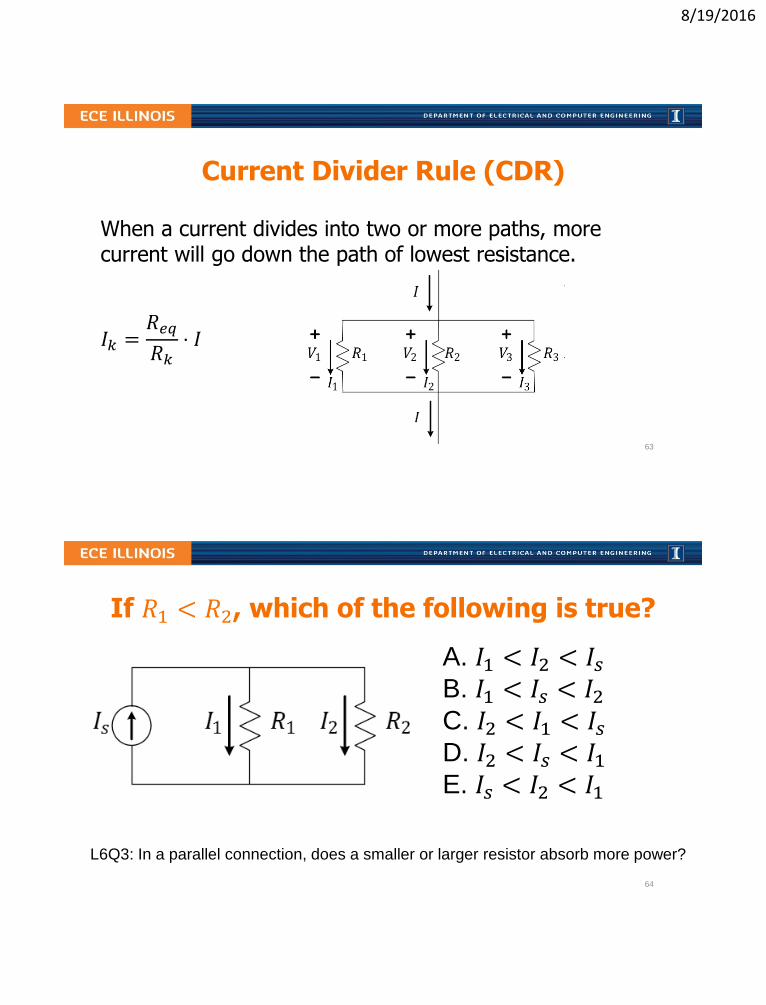
Current Divider Rule (CDR)
When a current divides into two or more paths, more current will go down the path of lowest resistance.
𝐼𝑘 =𝑅𝑒𝑞
𝑅𝑘⋅ 𝐼
63
If 𝑅1 < 𝑅2, which of the following is true?
A. 𝐼1 < 𝐼2 < 𝐼𝑠B. 𝐼1 < 𝐼𝑠 < 𝐼2C. 𝐼2 < 𝐼1 < 𝐼𝑠D. 𝐼2 < 𝐼𝑠 < 𝐼1E. 𝐼𝑠 < 𝐼2 < 𝐼1
L6Q3: In a parallel connection, does a smaller or larger resistor absorb more power?
64

8/19/2016
VDR and CDR for Two Resistances
𝑉1 =𝑅1𝑅1 + 𝑅2
𝑉
𝑉2 =𝑅2𝑅1 + 𝑅2
𝑉
𝐼1 =𝑅2𝑅1 + 𝑅2
𝐼 𝐼2 =𝑅1𝑅1 + 𝑅2
𝐼
L6Q4: If 6V falls across a series combination of 1kΩ and 2kΩ, what is V across 2kΩ?
L6Q5: If 0.15A flows through a parallel combo of 1kΩ and 2kΩ, what is I through 2kΩ?
L6Q6: If a source supplies 60W to a series combination of 10Ω and 30Ω, what is the
power absorbed by the 10Ω resistor? What is absorbed by the 30Ω resistor?
L6Q7: If a source supplies 300mW to a parallel combination of 3kΩ and 2kΩ, what is the
power absorbed by the 3kΩ resistor? What is absorbed by the 2kΩ resistor? 65
L6 Learning objectives
a. Identify series and parallel connections within a circuit network
b. Find equivalent resistance of circuit networks
c. Estimate resistance by considering the dominant elements
d. Apply rules for current and voltage division to these networks
e. Apply conservation of energy to components within a circuit network
66

8/19/2016
Lecture 7: More on Sources and Power
• The Meaning of Current and Voltage Sources
• Labeling of Current and Voltage and Sign of Power
• Time Varying Voltage Source – Sinusoidal, Square, Etc.
• Root-Means-Square Voltage (RMS) of a Waveform
67
Voltage and Current Sources CanProduce or Consume Power and Energy
• [Ideal] sources in a circuit are mathematical models
• Can be used to model real devices (or parts of circuit)
• Voltage sources have (calculable) currents through them
• Current sources have (calculable) voltages across them
• Source elements can produce or consume energy
68

8/19/2016
Which of the sources are delivering power?
A. The voltage source only
B. The current source only
C. Both
D. Neither
E. Not enough information to tell
69
Either or Both Sources Can Supply Power
L7Q1: For what values of Is do both sources supply power?
L7Q2: For what values of Is does only the current source supply power?
L7Q3: For what values of Is does only the voltage source supply power?70

8/19/2016
Taking care of labeling
• Labeling of current direction and voltage polarity is important!
• For any element, we label current 𝐼 flowing through it from the positive side of 𝑉 to the negative side of 𝑉 or vice-versa
Preferable for resistors
Here, V=IRCan be conveniently used for sources
(If it’s a resistor, V = -IR)
L7Q4: In what direction does a positive current flow through a resistor?
L7Q5: In what direction does a positive current flow through a battery? 71
The sign of power is important
Recall: power (watts) is energy (joules) divided by time (sec)
𝑃 𝑡 = 𝑉 𝑡 𝐼 𝑡
𝑃 = 𝑉𝐼
if constant (aka. DC or Direct Current). Using the standard polarity labeling: 𝑃 = 𝑉+− 𝐼+→−
𝑃 < 0 ⇒ 𝐸𝑙𝑒𝑚𝑒𝑛𝑡 𝑑𝑒𝑙𝑖𝑣𝑒𝑟𝑠 𝑝𝑜𝑤𝑒𝑟 𝑡𝑜 𝑡ℎ𝑒 𝑐𝑖𝑟𝑐𝑢𝑖𝑡
𝑃 > 0 ⇒ 𝐸𝑙𝑒𝑚𝑒𝑛𝑡 𝑎𝑏𝑠𝑜𝑟𝑏𝑠 𝑝𝑜𝑤𝑒𝑟 𝑓𝑟𝑜𝑚 𝑡ℎ𝑒 𝑐𝑖𝑟𝑐𝑢𝑖𝑡
72

8/19/2016
Recap of labeling implication
𝑅 =𝑉
𝐼
𝑃 = 𝑉𝐼
𝑅 = −𝑉
𝐼
𝑃 = −𝑉𝐼
Where power is defined in such a way that it is negative when it
is supplied (sourced) and positive when it is absorbed (sinked).
L7Q6: With power defined as above, what is the sum of Ps for all circuit elements?73
Which of the sources below absorbs power?
A.
B.
C.
D. E.74
8/19/2016
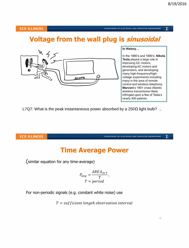
Voltage from the wall plug is sinusoidal
L7Q7: What is the peak instantaneous power absorbed by a 250Ω light bulb?
In History…
In the 1880’s and 1890’s, Nikola
Tesla played a large role in
improving DC motors,
developing AC motors and
generators, and developing
many high-frequency/high-
voltage experiments including
many in the area of remote
control and wireless telephony.
Marconi’s 1901 cross-Atlantic
wireless transmission likely
infringed upon a few of Tesla’s
nearly 300 patents.
75
Time Average Power
(similar equation for any time-average)
𝑃𝑎𝑣𝑔 =𝐴𝑅𝐸𝐴𝑖𝑛 𝑇𝑇,
𝑇 = 𝑝𝑒𝑟𝑖𝑜𝑑
For non-periodic signals (e.g. constant white noise) use
𝑇 = 𝑠𝑢𝑓𝑓𝑖𝑐𝑖𝑒𝑛𝑡 𝑙𝑒𝑛𝑔𝑡ℎ 𝑜𝑏𝑠𝑒𝑟𝑣𝑎𝑡𝑖𝑜𝑛 𝑖𝑛𝑡𝑒𝑟𝑣𝑎𝑙
76

8/19/2016
Root-Mean-Square averages
RMS is meaningful when interested in power production/dissipation in AC.
𝑉𝑅𝑀𝑆 = 𝐴𝑣𝑒𝑟𝑎𝑔𝑒 𝑣2 𝑡
1. Sketch 𝑣2(𝑡)
2. Compute 𝐴𝑣𝑒𝑟𝑎𝑔𝑒 𝑣2 𝑡
3. Take of the value found in part 2.
77
Calculating Pavg and Vrms
L7Q8: What is the average power absorbed by a 250Ω light bulb if A = 170V?
𝑇𝑟𝑖𝑔 𝑖𝑑𝑒𝑛𝑡𝑖𝑡𝑦: cos 𝐴 cos 𝐵 =1
2cos 𝐴 − 𝐵 + cos 𝐴 + 𝐵
78

8/19/2016
Calculating Pavg and Vrms
L7Q9: What happens to power and Vrms when TON is halved while T is unchanged?
…𝐷𝑢𝑡𝑦 𝐶𝑦𝑐𝑙𝑒 𝐷𝑒𝑓𝑖𝑛𝑖𝑡𝑖𝑜𝑛:
𝑇𝑂𝑁𝑇
79
L7 Learning Objectives
a. Correctly apply Ohm’s law in a resistor (depending on labeling)
b. Determine whether power is absorbed or supplied by an element
c. Compute the time-average power from I(t), V(t) curves
d. Explain the meaning of Vrms and relationship to Pavg
80
8/19/2016
Lecture 8: IV Characteristics
• Measuring I-V Characteristics of Circuits
• Calculating I-V Characteristics of Linear Circuits
• Operating (I,V) point when Sub-circuits are Connected
• Power and the I-V Characteristics
81
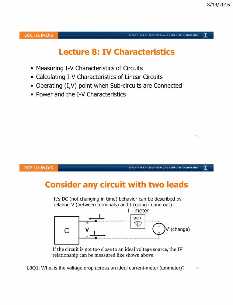
Consider any circuit with two leads
It’s DC (not changing in time) behavior can be described by relating V (between terminals) and I (going in and out).
C+
V
-
I
I
+
-V (change)
I - meter
If the circuit is not too close to an ideal voltage source, the IV relationship can be measured like shown above.
L8Q1: What is the voltage drop across an ideal current-meter (ammeter)? 82

8/19/2016
Alternative IV measurements
C+
V
-
I
II (change)V- meter
C+
V
-
I
I
A variable resistor load is very practical when the circuit C provides power.
R (change)V- meter
I - meter
L8Q2: What is the current through an ideal voltage-meter (voltmeter)? 83
Linear I-V curves
I
V
I
V
I
V
I
V
A. B.
C. D.
L8Q3: Which set of graphs corresponds to pure resistances? 84

8/19/2016
Simple Series Circuit
L8Q4: What are the IV characteristics of the circuit above? Include the graph.
𝐼
𝑉
Show that the circuit has a linear IV characteristic.
85
Embedded Voltage Source
L8Q5: What are the IV characteristics of the circuit above? Include the graph.
𝐼
𝑉
Show that this circuit also has a linear IV characteristic.
86

8/19/2016
Why we care• Allows easy calculation of I and V when two sub-circuits are connected together
• Allows creating a simpler model of a given sub-circuit
• Helps understand nonlinear devices
• Use circuit analysis for variable V
• Find two points (usually open and short)
• Use Reff and either open or short (Wednesday)
How to find IV lines
87
Linear I-Vs of source-resistor circuits
Any combination of current or voltage sources with resistor networks has a linear I-V (between any two nodes).
L8Q6: What are the current values 𝐼 assumes when 𝑉 is 0V, 2V, 4V?
𝐼
𝑉
88

8/19/2016
I-V line for different nodes
L8Q7: What are the current values taken by 𝐼1 when 𝑉1 is 0V, 2V, 4V?
𝐼1
𝑉1
89
Connecting two sub-circuits
L8Q8: What are the IV characteristics of a 3 mA current source?
L8Q9: What are the IV characteristics of a 3 kΩ resistor?
or
𝐼(mA) = V/3-3
90
8/19/2016
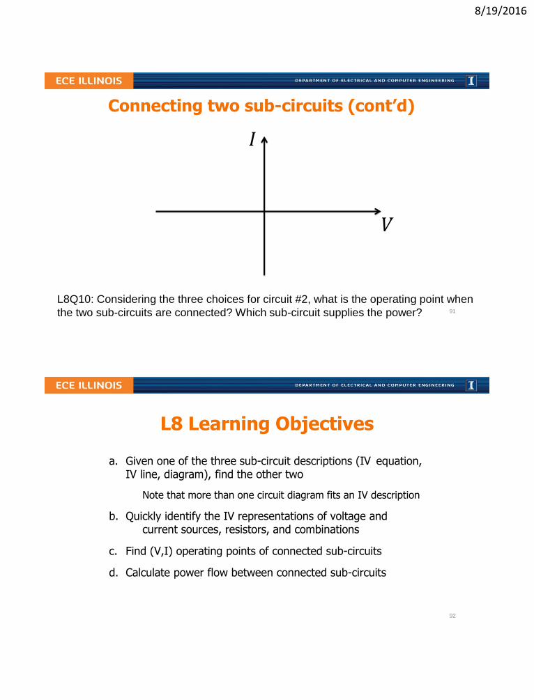
Connecting two sub-circuits (cont’d)
L8Q10: Considering the three choices for circuit #2, what is the operating point when
the two sub-circuits are connected? Which sub-circuit supplies the power?
𝐼
𝑉
91
L8 Learning Objectives
a. Given one of the three sub-circuit descriptions (IV equation, IV line, diagram), find the other two
Note that more than one circuit diagram fits an IV description
b. Quickly identify the IV representations of voltage and current sources, resistors, and combinations
c. Find (V,I) operating points of connected sub-circuits
d. Calculate power flow between connected sub-circuits
92

8/19/2016
Lecture 9: Thevenin and Norton Equivalents
• Review of I-V Linear Equation
• Thevenin and Norton Equivalent Circuits
• Thevenin-Norton Transformation in Circuits
• Calculating Reff by Removing Sources
• Problem Strategy and Practice
93
Relating I-V Line to Equation
C
I
+
V
-I
C
I
+
V
-I
Universal: 𝐼 = 𝐼𝑠𝑐 −𝐼𝑠𝑐
𝑉𝑜𝑐𝑉
𝐼 = 𝐼𝑠𝑐 −1
𝑅𝑒𝑓𝑓𝑉
𝐼 = 𝐼𝑠𝑐 +1
𝑅𝑒𝑓𝑓𝑉
𝑅𝑒𝑓𝑓=𝑉𝑜𝑐𝐼𝑠𝑐
𝑅𝑒𝑓𝑓= −𝑉𝑜𝑐𝐼𝑠𝑐
94

8/19/2016
Thevenin and Norton Equivalents
• Either can be used to represent universal: 𝐼 = 𝐼𝑠𝑐 −𝐼𝑠𝑐
𝑉𝑜𝑐𝑉
• Contain all information on how circuits interact with other circuits
• Loses information on power dissipation WITHIN the circuit
The circuit on the left and
the circuit on the right can
be made to behave identically
by the choice of values as seen
through the terminals.
95
Using Transformation to Find Equivalents
L9Q1: What is the Thevenin equivalent of the circuit above? 96

8/19/2016
Reff = RT = RN is Req with sources removed
1. Short-circuit all voltage sources (i.e. set them to zero)
2. Open-circuit all current sources (i.e. set them to zero)
3. Find resulting 𝑅𝑒𝑞 using parallel and series relationships
L9Q2: How is 𝑅𝑒𝑓𝑓 related to the slope of the I-V line?
⇒ ⇒
97
Finding Reff is easy in multi-source circuits
L9Q3: What is 𝑅𝑒𝑓𝑓, for the circuit above?
L9Q4: Besides 𝑅𝑒𝑓𝑓, is it easier to find 𝐼𝑆𝐶 or 𝑉𝑂𝐶?
A. 8 ΩB. 5 ΩC. 4 ΩD. 2 ΩE. 0.8 Ω
98

8/19/2016
One can find a circuit given a line
L9Q5: What is 𝑅𝑒𝑓𝑓, for the circuit with the given I-V line?
𝑅𝑒𝑓𝑓
𝑅𝑒𝑓𝑓
99
Practice makes perfect!
L9Q6: What are the Thevenin and Norton equivalents for the circuit above?
In History…
Leon Charles Thevenin was a
telegraph engineer. In 1883, his
theorem expanded modelling of
circuits and simplified circuit
analysis based on Ohm’s Law
and Kirchhoff’s Laws.
The dual “Norton’s theorem”
didn’t arrive until 1926 with the
efforts of Bell Labs engineer,
Edward Lawry Norton.
100

8/19/2016
Summary
• Any linear network can be represented by a simple series Thévenin circuit or, equivalently, by a simple parallel Norton circuit
• There are several methods for determining the quantities and depending on what is given about the original circuit
• It is the same resistance, 𝑅𝑒𝑓𝑓, value for both the
Thévenin and the Norton circuits, found as 𝑅𝑒𝑞 with the
sources removed (SC for V-sources, OC for I-sources)
101
L9 Learning Objectives
a. Represent any (non-horizontal) linear IV characteristic by a series combination of a voltage source and a resistor (Thévenin equivalent circuit).
b. Represent any (non-vertical) linear IV characteristic by a parallel combination of a current source and a resistor (Norton equivalent circuit).
c. Find the parameters of Thévenin and Norton equivalent circuits, 𝑅𝑒𝑓𝑓, 𝑉𝑇 , and 𝐼𝑁 when given a circuit.
102

8/19/2016
Lecture 10: Node Method For Circuit Analysis
• Review of circuit-solving strategies
• Node Method steps
• Practice with the Node Method
103
What are the possible strategies to find 𝐼?
L10Q1: Is one of the resistors in parallel with the voltage source? If so, which?
L10Q2: What is the value of the labeled current? 104

8/19/2016
The Node Method
1. Identify or pick “ground” (0 V reference)
2. Label all the node voltages (use values when you can; variables when you must)
3. Use KCL at convenient node(s)/supernode(s)
4. Use voltages to find the currents
105
Node method is a good strategy for this problem because it contains two sources
L10Q3: How many nodes are in the circuit?
L10Q4: What is the value of the labeled current?
A. 1
B. 2
C. 3
D. 4
E. 5
106

8/19/2016
A floating voltage source relates two nodes
A. 1
B. 2
C. 3
D. 4
E. 5
L10Q5: How many nodes are in the circuit?
L10Q6: What is the value of the labeled current? 107
Voltage across a current source is unknown
L10Q7: What is the power supplied or consumed by each element? 108

8/19/2016
Sometimes two or more node voltages are unknown (more challenging!)
L10Q8: What is the value of I in the circuit above? 109
L10 Learning Objectives
a. Outline (list, describe) steps of the Node Method
b. Use these steps to speed the process of performing circuit analysis via KCL/KVL/Ohm’s
c. Identify circuit patterns in which different techniques might simplify the process of finding a solution (Practice!)
110

8/19/2016
Lecture 11: Introduction to Diodes
• Diode IV characteristics
• Connecting diode to a linear circuit
• Piecewise linear models of diodes
Recommended: https://learn.sparkfun.com/tutorials/diodes
111
Diode as a two-terminal deviceI
V
Major applications: lighting, electronics
Made out of semiconductor materialslike Si, Ge, AlGaAs, GaN withsome additives called dopants.
𝐼 ≈ 𝐼𝑆 𝑒𝑉/𝑛𝑉𝑡ℎ𝑒𝑟𝑚 − 1
L11Q1: Based on the exponential equation for IV, can the diode supply power?112

8/19/2016
Connecting diode to a linear circuitI
V
We can solve graphically for an operating point.For an LED more current means more light.
L11Q2: What is the current flowing through the diode if VT < 0? 113
Modeling diode with linear IV segments I
V
Instead of looking for graphical solutions, we can approximate the diode with twoline segments, corresponding to diode’sregimes of operation.
L11Q3: What is the minimum VT of the connected linear circuit which causescurrent to flow through the diode if the piecewise linear model above is used?
114

8/19/2016
Different diode types have different VON
Diode Type VON(V) Applications
Silicon 0.6-0.7 General; integrated circuits; switching, circuit
protection, logic, rectification, etc.
Germanium ~0.3 Low-power, RF signal detectors
Schottky 0.15-0.4 Power-sensitive, high-speed switching, RF
Red LED (GaAs) ~2 Indicators, signs, color-changing lighting
Blue LED (GaN) ~3 Lighting, flashlights, indicators
“Ideal” 0 Can neglect VON for high voltage applications
L11Q4: What is the power dissipated by a Ge diode if 30 mA is flowing through it?115
Diode circuit examples (offset ideal model)
Assume offset-ideal model with VON = 0.7 (common Si diodes)L11Q5: What is the current through the diode in the top left circuit?L11Q6: What is the current through the diode in the top right circuit?
116

8/19/2016
Diode circuit examples (offset ideal model)
Assume offset-ideal model with VON = 0.7 (common Si diodes)L11Q7: What is the current through the diode in the circuit?
L11Q7:
𝐼𝐷 =A. −11.5 𝑚𝐴B. −2.5 𝑚𝐴C. 0 𝑚𝐴D. +2.5 𝑚𝐴E. +11.5 𝑚𝐴
117
L11 Learning Objectives
a. Draw a “typical” diode IV curve and describe its shape
b. Explain how to use graphical analysis to find the operating point of a diode connected to a linear circuit
c. Describe the offset ideal diode model (open, V-source)
d. Solve simple circuit problems with one diode, given VON
118
8/19/2016
Lecture 12: Diode Circuits
• Guess-and-check for diode circuits
• Current-limiting resistors and power dissipation
• Voltage-limiting (clipping) diode circuits
119
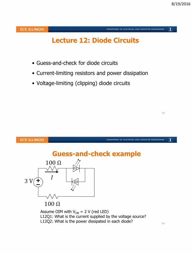
Guess-and-check example
Assume OIM with VON = 2 V (red LED)L12Q1: What is the current supplied by the voltage source?L12Q2: What is the power dissipated in each diode?
D1
D2
120

8/19/2016
Back-to-back diodes in series are modeled by OIM as an open circuit
A. 0 𝐴𝑚𝑝𝑠
B. 0.2 𝐴𝑚𝑝𝑠
C. 0.33 𝐴𝑚𝑝𝑠
D. 0.4 𝐴𝑚𝑝𝑠
E. 3.3 𝐴𝑚𝑝𝑠
L12Q3: Assume OIM with VON = 0.7 V (Si)What is the current through the left-most diode? 121
Another guess-and-check example
L12Q4: How many red LEDs are turned on in the circuit above? (Use OIM)
𝑉𝑜𝑛 = 2 𝑉
1
2
3
4
5
6
7
ECE Spotlight…
The first visible-light LED was
developed by University of Illinois
alumnus (and, later, professor) Nick
Holonyak, Jr., while working at General
Electric in 1962 with unconventional
semiconductor
materials.
He immediately
predicted the
widespread
application
of LED lighting
in use today.
122

8/19/2016
Current-limiting resistors for LEDs
Assume OIM with VON = 3.3 V (blue LED)L12Q5: How many 1.5 V batteries are needed to turn on the LED?L12Q6: What is the series resistance needed to get 16 mA through the LED?L12Q7: What is the resulting power dissipation in the diode?
123
Setting voltage limits with diodes
Assume linear model with VON = 0.3 V (Ge diode)L12Q8: What is the possible range of the output voltages in the left circuit?L12Q9: What is the possible range of the output voltages in the right circuit?
124

8/19/2016
A voltage-clipping circuit sets maximum or minimum output voltage
i
R
+
VOUT
–
+vD–
60 V
KVL:
VOUT = 60 + vD
+
–VIN = 100 sint
𝑉𝐼𝑁
L12Q10: If the input voltage waveform is shown, what is the output waveform, assuming an ideal diode model (VON = 0 V)? 125
L12 Learning Objectives
a. Solve circuit analysis problems involving sources, resistances, and diodes
b. Estimate power dissipation in diode circuits
c. Select appropriate current-limiting resistors
d. Determine voltage limits and waveforms at outputs of diode voltage-clipping circuits
126

8/19/2016
Lecture 13: Catchup and Examples
• We will use this lecture to catch up, if needed
• We will also practice solving circuits
• The slides will be distributed
127
Lecture 14: Hour Exam #1 Review
• This lecture is OPTIONAL, but highly recommended!
• Attendance will not be taken
• We will use this lecture for last minute review
• We will focus on muddy points
• Plan to study ahead of time
• More info TBA
128

8/19/2016
L15: The Bipolar Junction Transistor (BJT)
• BJT is a controlled current source…
– current amplifier
• The three operating regimes of a BJT
• Controlling a resistive load with a BJT
• Solving for saturation condition
B: Base
C: Collector
E: Emitter
ECE Spotlight…
John Bardeen, the co-inventer
of the transistor, was also the
Ph.D. advisor at the University
of Illinois for Nick Holonyak, Jr.
of LED fame.
129
IV Characteristic of a 3-terminal Device??
No single way to connect three-terminal device to a linear circuit.130

8/19/2016
ECE110 considers only the “common-emitter” configuration
If we fix 𝐼𝐵, we can measure the resulting 𝐼 and 𝑉 at the other side.
131
The BJT’s “common-emitter NPN” model
Constraints:
• Limited current range: 𝛽𝐼𝐵 ≥ 0
• Limited voltage range: 𝑉𝑜𝑢𝑡 > 0
L15Q1: Given these constraints, can this “dependent” current source deliver power?
132
8/19/2016
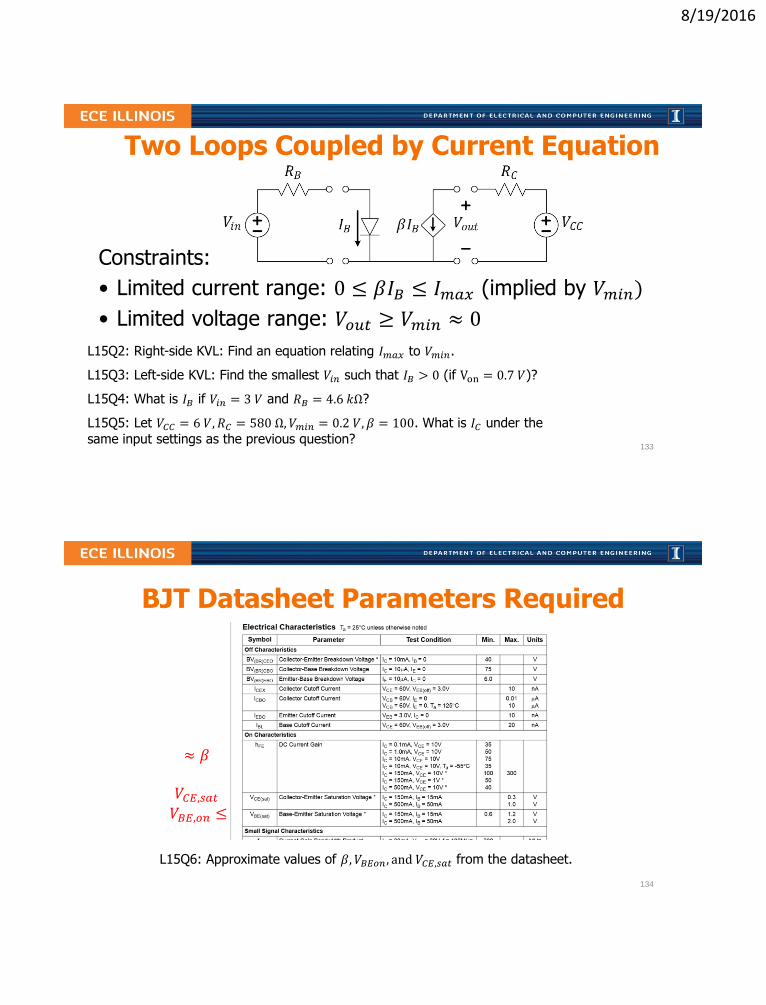
Constraints:
• Limited current range: 0 ≤ 𝛽𝐼𝐵 ≤ 𝐼𝑚𝑎𝑥 (implied by 𝑉𝑚𝑖𝑛)
• Limited voltage range: 𝑉𝑜𝑢𝑡 ≥ 𝑉𝑚𝑖𝑛 ≈ 0
L15Q2: Right-side KVL: Find an equation relating 𝐼𝑚𝑎𝑥 to 𝑉𝑚𝑖𝑛.
L15Q3: Left-side KVL: Find the smallest 𝑉𝑖𝑛 such that 𝐼𝐵 > 0 (if Von = 0.7 𝑉)?
L15Q4: What is 𝐼𝐵 if 𝑉𝑖𝑛 = 3 𝑉 and 𝑅𝐵 = 4.6 𝑘Ω?
L15Q5: Let 𝑉𝐶𝐶 = 6 𝑉, 𝑅𝐶 = 580 Ω, 𝑉𝑚𝑖𝑛 = 0.2 𝑉, 𝛽 = 100. What is 𝐼𝐶 under the
same input settings as the previous question?
Two Loops Coupled by Current Equation
133
BJT Datasheet Parameters Required
L15Q6: Approximate values of 𝛽, 𝑉𝐵𝐸𝑜𝑛 , and 𝑉𝐶𝐸,𝑠𝑎𝑡 from the datasheet.
≈ 𝛽
𝑉𝐶𝐸,𝑠𝑎𝑡𝑉𝐵𝐸,𝑜𝑛 ≤
134

8/19/2016
BJT in Active Region
BJT datasheet parameters:
• 𝛽 = 100
• 𝑉𝐵𝐸,𝑜𝑛 = 1 𝑉
• 𝑉𝐶𝐸,𝑠𝑎𝑡 = 0.2 𝑉
L15Q7: Find 𝐼𝐵.L15Q8: Find 𝐼𝐶.
L15Q7:A. 𝐼𝐵 = 0 𝜇𝐴B. 𝐼𝐵 = 1 𝜇𝐴C. 𝐼𝐵 = 2 𝜇𝐴D. 𝐼𝐵 = 10 𝜇𝐴E. 𝐼𝐵 = 100 𝜇𝐴
135
BJT in Cutoff
BJT datasheet parameters:
• 𝛽 = 100
• 𝑉𝐵𝐸,𝑜𝑛 = 1 𝑉
• 𝑉𝐶𝐸,𝑠𝑎𝑡 = 0.2 𝑉
L15Q9: Find 𝐼𝐵.L15Q10: Find 𝐼𝐶.
136

8/19/2016
BJT in Saturation
BJT datasheet parameters:
• 𝛽 = 100
• 𝑉𝐵𝐸,𝑜𝑛 = 1 𝑉
• 𝑉𝐶𝐸,𝑠𝑎𝑡 = 0.2 𝑉
L15Q11: Find 𝐼𝐵.L15Q12: Find 𝐼𝐶.
137
BJT Exercise
BJT datasheet parameters:
• 𝛽 = 100
• 𝑉𝐵𝐸,𝑜𝑛 = 1 𝑉
• 𝑉𝐶𝐸,𝑠𝑎𝑡 = 0.2 𝑉
L15Q13: Find 𝐼𝐶 and identify in which regime the transistor is operating.
138

8/19/2016
BJT Exercise
BJT datasheet parameters:
• 𝛽 = 100
• 𝑉𝐵𝐸,𝑜𝑛 = 1 𝑉
• 𝑉𝐶𝐸,𝑠𝑎𝑡 = 0.2 𝑉
L15Q14: Find 𝐼𝐶 and identify in which regime the transistor is operating.
L15Q15: Determine the power consumed by the transistor.
mA
139
L15 Learning Objectives
a. Identify B, E, C terminals on an npn-BJT symbol
b. Explain BJT’s three regimes of operation
c. Calculate active-regime 𝐼𝐶 using 𝑉𝐵𝐸𝑜𝑛 in the BE loop
d. Calculate maximum 𝐼𝐶 based on 𝑉𝐶𝐸,𝑠𝑎𝑡 and CE loop
e. Calculate 𝐼𝐶 given complete biasing conditions and transistor parameters, no matter which regime
f. Calculate the power dissipated by a transistor
140

8/19/2016
Lecture 16: BJT IV Characteristics
• Interpreting CE junction IV curves for transistor parameters
• Interpreting load line IV curves
• Analysis of IV curves for the (I,V) operating point
• Explore the saturation condition
• Solving transistor-regime problems
141
BJT IV curves of the CE junction
1 2 3 4 5 6 𝑉𝐶𝐸 (𝑉)
𝐼𝐶 (𝑚𝐴)2.0
1.5
1.0
0.5 𝐼𝐵 = 10𝜇𝐴
𝐼𝐵 = 20𝜇𝐴
𝐼𝐵 = 30𝜇𝐴
𝐼𝐵 = 40𝜇𝐴
𝑉𝐶𝐸,𝑠𝑎𝑡L16Q1: Use the IV plots above to estimate the value of 𝛽.
Constraints:
• 0 ≤ 𝛽𝐼𝐵 ≤ 𝐼𝐶,𝑠𝑎𝑡
• 𝑉𝑜𝑢𝑡 ≥ 𝑉𝐶𝐸,𝑠𝑎𝑡 > 0
142

8/19/2016
Extracting information from the IV curve(s)
1 2 3 4 5 6
(𝑚𝐴)
4
3
2
1𝐼𝐵 = 10𝜇𝐴
𝐼𝐵 = 20𝜇𝐴𝐼𝐵 = 30𝜇𝐴
𝐼𝐵 = 40𝜇𝐴
(𝑉)
L16Q2: What is 𝛽 and 𝑉𝐶𝐸,𝑠𝑎𝑡?
L16Q3: What is 𝑉𝐶𝐶?L16Q4: What is 𝑅𝐶?L16Q5: What is 𝐼𝐶,𝑠𝑎𝑡?
L16Q6: Which 𝐼𝐵 results in saturation?
L16Q6:A. 𝐼𝐵 = 40𝜇𝐴B. 𝐼𝐵 = 30𝜇𝐴C. 𝐼𝐵 = 20𝜇𝐴D. 𝐼𝐵 = 10𝜇𝐴E. 𝐼𝐵 = 0𝜇𝐴
143
L16Q7: Estimate the operating point (𝐼𝐶 , 𝑉𝐶𝐸) when 𝑉𝑖𝑛 = 1.7 𝑉.
L16Q8: What value of 𝑉𝑖𝑛 would drive the transistor to the edge of saturation?
BJT Exercise
1 2 3 4 5 6
(𝑚𝐴)
40
30
20
10 𝐼𝐵 = 100 𝜇𝐴
𝐼𝐵 = 200 𝜇𝐴
𝐼𝐵 = 300 𝜇𝐴
𝐼𝐵 = 400 𝜇𝐴
(𝑉)
𝑉𝑖𝑛 7.5 𝑉
𝑉𝐵𝐸,𝑜𝑛 = 0.7 𝑉
144

8/19/2016
L16Q9: What value of 𝑉𝑖𝑛 would drive the transistor to the edge of saturation?
L16Q10: How does your answer change if 30 𝑘Ω were replaced with 60 𝑘Ω?
L16Q11: How does your answer change if, instead, 350 Ω → 700 Ω?
BJT ExerciseBJT datasheet parameters:
• 𝛽 = 100
• 𝑉𝐵𝐸,𝑜𝑛 = 0.7 𝑉
• 𝑉𝐶𝐸,𝑠𝑎𝑡 = 0.2 𝑉
L16Q10:
A. 𝑉𝑖𝑛@𝑠𝑎𝑡 goes up
B. 𝑉𝑖𝑛@𝑠𝑎𝑡 goes down
C. 𝑉𝑖𝑛@𝑠𝑎𝑡 stays the same
L16Q11:
A. 𝑉𝑖𝑛@𝑠𝑎𝑡 goes up
B. 𝑉𝑖𝑛@𝑠𝑎𝑡 goes down
C. 𝑉𝑖𝑛@𝑠𝑎𝑡 stays the same145
BJT circuit analysis: working back to 𝑽𝒊𝒏BJT Datasheet: 𝛽 = 100,𝑉𝐵𝐸𝑜𝑛 = 0.7𝑉, 𝑉𝐶𝐸,𝑠𝑎𝑡 = 0.2𝑉
L16Q12: Find 𝑉𝑖𝑛 such that 𝑉𝐶𝐸 = 3 𝑉
1 𝑘Ω
146

8/19/2016
BJT circuit analysisBJT Datasheet:
• 𝛽 = 100,
• 𝑉𝐵𝐸𝑜𝑛 = 0.7 𝑉
• 𝑉𝐶𝐸,𝑠𝑎𝑡 = 0.2 𝑉
L16Q13: Choose 𝑅𝐵 such that the BJT is driven to the edge of saturation.
1 𝑘Ω
4.2 𝑉
𝑅𝐵
147
L16 Learning Objectives
a. Find 𝛽 and 𝑉𝐶𝐸,𝑠𝑎𝑡 for a given BJT IV characteristic
b. Find 𝑉𝐶𝐶 and 𝑅𝐶 from the IV characteristic of the load line
c. Compute 𝐼𝐶,𝑠𝑎𝑡 from 𝑉𝐶𝐶 , 𝑉𝐶𝐸,𝑠𝑎𝑡, and 𝑅𝐶
d. Identify the BJT CE operating point given IV characteristics
e. Solve numerically for unknown parameters among 𝑉𝑖𝑛, 𝑅𝐵 , 𝐼𝐵 , 𝛽, 𝑉𝐵𝐸,𝑜𝑛, 𝑉𝐶𝐸,𝑠𝑎𝑡, 𝐼𝐶 , 𝑅𝐶 , 𝑉𝐶𝐶 , 𝐼𝐶,𝑠𝑎𝑡 when given some or all of the
other values
f. Determine settings to drive transistor into a desired regime
148

8/19/2016
Lecture 17: The BJT Voltage Amplifier• Relating 𝑉𝑜𝑢𝑡 to 𝑉𝑖𝑛
• Node notation for 𝑉𝐶𝐶
• Voltage transfer function
• AC signal amplification
149
Calculating 𝑽𝒐𝒖𝒕 from 𝑽𝒊𝒏 (revisited)
L17Q1: What is 𝑣𝑜𝑢𝑡 = 𝑉𝐶𝐸 for 𝑉𝐼𝑁 = 0.3, 1, 2.5, and 3.5 Volts?
30 𝑘Ω
1 𝑘Ω
6 𝑉BJT Datasheet:
• 𝛽 = 100
• 𝑉𝐵𝐸,𝑜𝑛 = 0.7𝑉
• 𝑉𝐶𝐸,𝑠𝑎𝑡 = 0.2𝑉
Vin IB
.3 0
1 .3/30k=.01m
2.5 1.8/30k=.06
m
3.5 2.8/30k=.09
m
150

8/19/2016
Review of BJT operating regimes
Regime Vin IB IC VC
L17Q2: What is the formula for minimum 𝑉𝐼𝑁 which causes saturation?
𝑉𝑜𝑢𝑡
𝑉𝑖𝑛
A. 𝑉𝑖𝑛 =𝑉𝐶𝐶−𝑉𝐶𝐸,𝑠𝑎𝑡
𝑅𝐶
B. 𝑉𝑖𝑛 = 𝑉𝐶𝐶 + 𝑉𝐵𝐸𝑜𝑛
C. 𝑉𝑖𝑛 = 𝑉𝐶𝐸,𝑠𝑎𝑡 + 𝐼𝐵𝑅𝐵
D. 𝑉𝑖𝑛 = 𝑉𝐶𝐶 − 𝐼𝐶𝑅𝐶 + 𝐼𝐵𝑅𝐵
E. 𝑉𝑖𝑛 = 𝑉𝐵𝐸𝑜𝑛 +𝑅𝐵
𝛽𝑅𝐶(𝑉𝐶𝐶 − 𝑉𝐶𝐸,𝑠𝑎𝑡)
151
30 𝑘Ω
1 𝑘Ω
6 𝑉
Voltage transfer characteristics𝛽 = 100𝑉𝐵𝐸,𝑜𝑛 = 0.7𝑉
𝑉𝐶𝐸,𝑠𝑎𝑡 = 0.2𝑉
L17Q3: What are the four values 𝑉𝑜1, 𝑉𝑜2, 𝑉𝑖1, 𝑉𝑖2?
L17Q4: What is the ∆𝑉𝑜𝑢𝑡
∆𝑉𝑖𝑛slope in the active region?
152

8/19/2016
Active regime for signal amplification
L17Q5: If 𝑉𝐼𝑁 = 1.2 + 0.2cos(2𝜋100𝑡) what is the equation for 𝑉𝑜𝑢𝑡?
L17Q6: What is different if 𝑉𝑖𝑛 = 1.2 + 0.6cos(2𝜋100𝑡)?
L17Q7: What transistor regimes are entered if 𝑉𝑖𝑛 = 1.1 + 0.3cos(𝜔𝑡)?
Consider
• 𝑉𝑖1 = 0.7 𝑉• 𝑉𝑖2 = 1.7 𝑉• 𝑉𝑜1 = 7.2 𝑉• 𝑉𝑜2 = 0.2 𝑉
153
L17 Learning Objectives
a. Explain the voltage transfer curve (𝑉𝑜𝑢𝑡 vs. 𝑉𝑖𝑛)
b. Find the transition points on the voltage transfer curve
c. Find the slope of the active region in the transfer curve
d. Determine the operating regions for an AC+DC input
e. Evaluate and AC+DC output for linear amplification
154

8/19/2016
Lecture 18: Catchup and Examplesor FORGE AHEAD!
155
156
8/19/2016
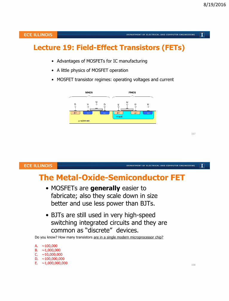
Lecture 19: Field-Effect Transistors (FETs)
• Advantages of MOSFETs for IC manufacturing
• A little physics of MOSFET operation
• MOSFET transistor regimes: operating voltages and current
157
The Metal-Oxide-Semiconductor FET
• MOSFETs are generally easier to fabricate; also they scale down in size better and use less power than BJTs.
• BJTs are still used in very high-speed switching integrated circuits and they are common as “discrete” devices.
Do you know? How many transistors are in a single modern microprocessor chip?
A. ~100,000B. ~1,000,000C. ~10,000,000D. ~100,000,000E. ~1,000,000,000
158

8/19/2016
To Produce a Conductive “Channel”Source and Body are tied together and 𝑉𝐺𝑆 > 𝑉𝑇𝐻 > 0
p
n
+
O
x
I
d
e
n
+m
e
t
a
l
m
e
t
a
l
𝑆𝑜𝑢𝑟𝑐𝑒
𝐺𝑎𝑡𝑒
𝐷𝑟𝑎𝑖𝑛
𝐵𝑜𝑑𝑦 (𝐵𝑢𝑙𝑘)
159
BJT (NPN) vs. MOSFET (n-channel)active region models
Active: IC = β IB Active: 𝐼𝐷 = 𝑘 ( 𝑉𝐺𝑆 − 𝑉𝑇𝐻)2
L19Q1: What happens to drain current when 𝑉𝐺𝑆 − 𝑉𝑇𝐻 doubles?
L19Q2: What is the DC current into the gate of the MOSFET model?
L19Q3: What are the units of 𝑘?
L19Q1: the drain current…A. halves
B. stays the same
C. doubles
D. triples
E. quadruples
ECE Spotlight…
Prof. Rosenbaum
emphasized in one 2016
paper, the need for
physically-accurate circuit
models to
predict and
protect against
electrostatic
discharge.Elyse Rosenbaum
University of Illinois
160

8/19/2016
Measuring nMOS IV-curves
Explore More!
ECE342, ECE340
“Active”
161
Family of nMOS IV-curves
L19Q4: If 𝐼1 = 100 𝑚𝐴, what is the value of 𝑘?
𝐼𝐷 = 𝑘 ( 𝑉𝐺𝑆 − 𝑉𝑇𝐻)2
L19Q6:A. 𝑘 = 100 𝑚𝐴/𝑉2
B. 𝑘 = 50 𝑚𝐴/𝑉2
C. 𝑘 = 25 𝑚𝐴/𝑉2
D. 𝑘 = 12.5 𝑚𝐴/𝑉2
E. 𝑘 = 1 𝑚𝐴/𝑉2
162
8/19/2016
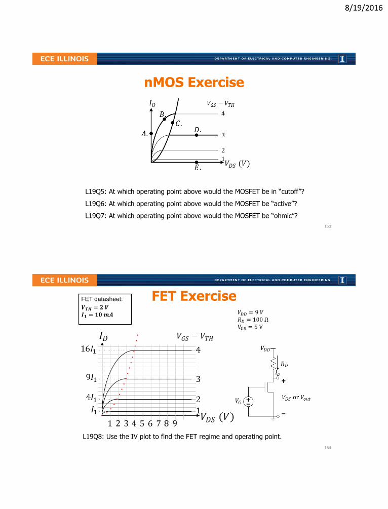
nMOS Exercise
L19Q5: At which operating point above would the MOSFET be in “cutoff”?
L19Q6: At which operating point above would the MOSFET be “active”?
L19Q7: At which operating point above would the MOSFET be “ohmic”?
163
FET Exercise
L19Q8: Use the IV plot to find the FET regime and operating point.
𝑉𝐷𝐷 = 9 𝑉𝑅𝐷 = 100 ΩVGS = 5 V
𝑽𝑻𝑯 = 𝟐 𝑽𝑰𝟏 = 𝟏𝟎𝒎𝑨
FET datasheet:
164

8/19/2016
FET Exercise
L19Q9: Find the Gate-to-Source voltage, 𝑉𝐺𝑆.
𝑉𝐷𝐷 = 9 𝑉𝑅𝐷 = 100 ΩVDS = 5 V
𝑽𝑻𝑯 = 𝟐 𝑽𝑰𝟏 = 𝟏𝟎𝒎𝑨
FET datasheet:
165
L19. Learning Objectives
a. To recognize the physics of enhancing/creating a channel in a MOS Transistor
b. To identify the regimes of nMOS with IV curves
c. To solve nMOS transistor problems using IV data
166

8/19/2016
Lecture 20: cMOS Logic
• cMOS logic and circuit models
• cMOS logic circuits and truth tables
• Switching a capacitive load
Idealized FET Model:
Logic “0”
Logic “1”
𝑉𝐷𝐷
0 𝑉
Logic Voltages
𝑉𝐷𝐷
0 𝑉167
n-channel MOSFET
Circuit Symbol Logic Symbol
L20Q1: What happens when a logical “1” is applied to the gate? 168
8/19/2016
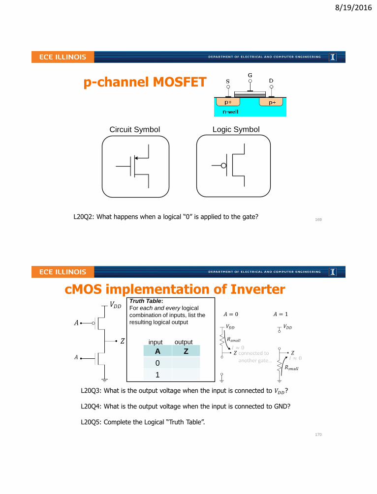
p-channel MOSFET
Circuit Symbol Logic Symbol
L20Q2: What happens when a logical “0” is applied to the gate?169
cMOS implementation of Inverter
L20Q3: What is the output voltage when the input is connected to 𝑉𝐷𝐷?
L20Q4: What is the output voltage when the input is connected to GND?
L20Q5: Complete the Logical “Truth Table”.
𝐴A Z
0
1
Truth Table:
For each and every logical
combination of inputs, list the
resulting logical output
input output
𝐴 = 0 𝐴 = 1
170

8/19/2016
A Two-Input cMOS Circuit
L20Q6: Complete the Truth Table.
A B Z
0 0 1
0 1 ρ
1 0 γ
1 1 0
L20Q6:A. ρ = 0, γ = 0B. ρ = 0, γ = 1C. ρ = 1, γ = 0D. ρ = 1, γ = 1E. Cannot determine
171
A Three-Input cMOS Circuit
L20Q7: Complete the Truth Tables.
172

8/19/2016
Improperly-Constructed cMOS Circuits
L20Q8: Attempt to complete the Truth Tables.
173
cMOS Energy
L20Q9: How much energy is stored in each gate (𝐶 = 1𝑓𝐹) if charged to 𝑉𝐷𝐷?
L20Q10: How much energy is consumed from the voltage source to charge it?
174

8/19/2016
Power consumed by a single switching FET
• Largest source of power consumption in computer chips
• Reduction of contributing factors is a technological goal
𝑃 = 𝑎 𝑓 𝐶 𝑉2𝑛
𝑎 – activity factor
𝑓– switching frequency
𝐶 – load capacitance
𝑉 – switching voltages
𝑛 – number of transistors switching
L20Q11: How many 2 𝑓𝐹 caps are switched at 1 𝑉 every ns to dissipate 100 𝑊?L20Q12: If the total number of transistors on a chip is 1 billion, what is 𝑎?
ECE Spotlight…
Profs. Pilawa-Podgurski and Hanumolu work
to produce useful circuits with small dimensions
that “can be implemented in small area and with
minimal power consumption while operating at
high [frequency].”
175
L20. Learning Objectives
a. To explain operation of a cMOS inverter
b. To interpret cMOS logic and express in Truth Table form
c. To calculate power consumption due to cMOS switching with capacitive loads
176

8/19/2016
Two-Input cMOS Circuit
L20Q13: Complete the Truth Table.
Learn It!
177
Two-Input cMOS Circuit
L20Q14: Complete the Truth Table.
Learn It!
178

8/19/2016
Lecture 21: Catchup and Examplesor FORGE AHEAD!
179
180

8/19/2016
Lecture 22: Hour Exam 2 Review
• Lecture is optional, but HIGHLY RECOMMENDED
• Will provide students a last opportunity to address outstanding questions
• Will focus on Muddy Points or problems specifically requested by students
181
Lecture 22: HE2 Coverage (tentative)
• L01-L21 (focused on L15-L21)
• HW1-HW10 (focused on HW7-HW10)
• Includes up through cMOS Logic, but not Signals, Spectra
• No Calculators, phones, or other electronic devices
• 25 multiple choice questions in 75 minutes
182

8/19/2016
Lecture 23: Signals, Spectra, and Noise• Electronic systems and signals
• Spectral representation of signals
• Noise - random fluctuations in signals
183
Analog and Digital Systems
Sensors A/D Computing D/AOutput
Devices
(digital
processing via
voltage levels)
What is an analog-to-digital converter?
What is being transferred to each “subsystem”?
Sensors Analog CircuitsOutput
Devices
184
8/19/2016
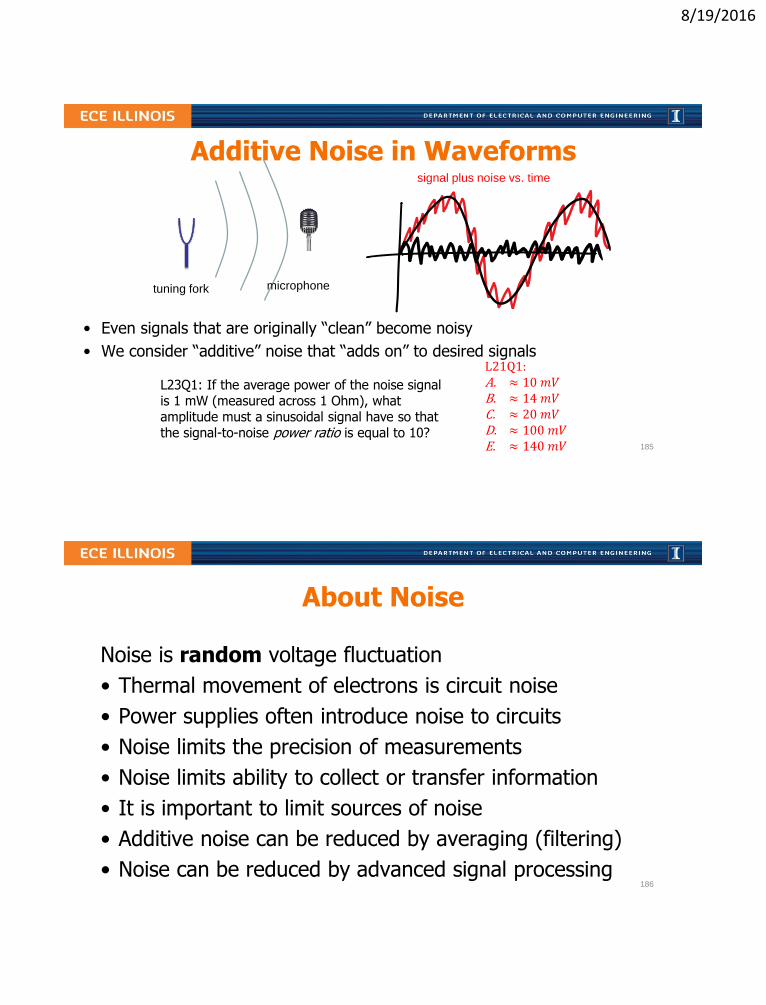
Additive Noise in Waveforms
• Even signals that are originally “clean” become noisy
• We consider “additive” noise that “adds on” to desired signals
L23Q1: If the average power of the noise signal is 1 mW (measured across 1 Ohm), what amplitude must a sinusoidal signal have so that the signal-to-noise power ratio is equal to 10?
tuning fork microphone
signal plus noise vs. time
L21Q1:A. ≈ 10 𝑚𝑉B. ≈ 14 𝑚𝑉C. ≈ 20 𝑚𝑉D. ≈ 100 𝑚𝑉E. ≈ 140 𝑚𝑉 185
About Noise
Noise is random voltage fluctuation
• Thermal movement of electrons is circuit noise
• Power supplies often introduce noise to circuits
• Noise limits the precision of measurements
• Noise limits ability to collect or transfer information
• It is important to limit sources of noise
• Additive noise can be reduced by averaging (filtering)
• Noise can be reduced by advanced signal processing186

8/19/2016
A Noisy DC MeasurementThermal noise in a sensor circuit can be dominant
• Noise power increases with temperature and resistance
• The average value of the noise is zero
L23Q2: How can we improve the precision of this VDR measurement?
Consider a voltage divider with a flex sensor.
187
Analog systems suffer from noise
Have you ever heard a noisy radio broadcast?
188

8/19/2016
Noise-Free Digital Communication?
How might you distinguish the different received levels?
189
Sinusoids Can Represent Analog Signals• We will represent electrical signals by waveforms 𝑣(𝑡)
• Any periodic waveform can be represented by sums (∑) of sinusoids (Fourier’s theorem/Fourier analysis)
𝑣 𝑡 =
𝑘
𝑣𝑘 𝑡 𝑣𝑘 𝑡 ∼ Ak cos 2π𝑓𝑘𝑡
• A “filter” is a system that selectively alters 𝐴𝑛𝑒𝑤 at each 𝑓𝑘
L23Q3: What is the frequency of 𝑣 𝑡 = 120 cos(2π200𝑡)?L23Q3b: 𝑣 𝑡 = 120 cos 2π200𝑡 + 120 cos(2𝜋400𝑡) goes in and 𝑦 𝑡 = 1.2 cos 2π200𝑡 +240cos(2𝜋400𝑡), what did this filter do?
Explore More!
ECE210 (or ECE211)
Unknown
SystemA cos 2π𝑓𝑘𝑡 Anew cos 2π𝑓𝑘𝑡 + 𝜃
190

8/19/2016
Spectra of Sinusoids and Sums𝑣(𝑡) 𝑅𝑀𝑆 𝑎𝑚𝑝𝑙𝑖𝑡𝑢𝑑𝑒
𝑓𝑟𝑒𝑞𝑢𝑒𝑛𝑐𝑦𝑡𝑖𝑚𝑒
191
Spectra of Other Signals
192

8/19/2016
Listing Frequencies of Periodic Signals
a. 𝑦(𝑡) = cos(2 𝜋 50 𝑡)
b. 𝑦(𝑡) = cos(100 𝜋 𝑡)
c. 𝑦(𝑡) = 2 cos(100 𝜋 𝑡) + 5 sin(100 𝜋 𝑡)
d. 𝑦(𝑡) = 3 + 2 cos(100 𝜋 𝑡) + 5 sin(300 𝜋 𝑡)
e. 𝑦(𝑡) = 3 + 2 cos(10 𝜋 𝑡) + 5 sin(300 𝜋 𝑡)
f. 𝑦(𝑡) = 3 + 2 cos(10 𝜋 𝑡) + 4 sin(100 𝜋 𝑡) + 5 sin(3000 𝜋 𝑡)
L23Q4: What is the highest frequency in each signal listed above?193
Lecture 23: Learning Objectives
a. Compute RMS voltages from a signal-to-noise power ratio
b. Explain thermal noise and its properties
c. Provide an argument for digital immunity to noise
d. Know basic statement of Fourier’s Theorem
e. Identify frequencies in sums of sinusoids
f. Recognize frequency-domain representation of signals
194

8/19/2016
L24: Sampling
• Noise-immunity motivation
• Describing waveforms by samples
• The sampling operation
195
How Would you Sketch this Waveform?
8
7
6
5
4
3
2
1
0
-1
-2
-3
-4
-5
-6
-7
v(t)
1 2 3 4 5 6 𝑡 (𝑠)
L24Q1: What are the values at t=0, 2, 4, and 6 seconds?
L24Q2: Is this enough information to reproduce the waveform?
196

8/19/2016
Enter Data Points of the Previous Waveform.
8
7
6
5
4
3
2
1
0
-1
-2
-3
-4
-5
-6
-7
v(t)
L24Q3: How should one connect the data points?
A. Point-to-point with straight lines.
B. Point-to-point with curvy lines.
C. Point-to-point, but only with horizontal and vertical lines.
When storing these values using bits, how many should we use?
(NEXT LECTURE!)
1 2 3 4 5 6 𝑡 (𝑠)
197
Sampling: Sensing real-world data at uniform intervals
𝑡[𝑠𝑒𝑐]
𝑣(𝑡) [𝑣𝑜𝑙𝑡𝑠] Sound
Sampled Sequence:
𝑣 𝑛 = 𝑣 𝑡 = 𝑛𝑇𝑠 , 𝑛 𝑖𝑛𝑡𝑒𝑔𝑒𝑟 (𝑛 = −2,−1,0,1,2,… )
Example: 𝑦 𝑡 = 5𝑡 𝑠𝑎𝑚𝑝𝑙𝑒𝑑 𝑎𝑡 𝑇𝑆 = 2Answer: 𝑦 𝑛 = 𝑦 𝑛𝑇𝑠 = 5n2 = 10n = ⋯ ,−20,−10,0,10,20, …
𝑇𝑠: 𝑆𝑎𝑚𝑝𝑙𝑖𝑛𝑔 𝑝𝑒𝑟𝑖𝑜𝑑
𝑓𝑠 =1
𝑇𝑠: 𝑆𝑎𝑚𝑝𝑙𝑖𝑛𝑔 𝐹𝑟𝑒𝑞𝑢𝑒𝑛𝑐𝑦
198

8/19/2016
Sampling
Sampled Sequence:
𝑣 𝑛 = 𝑣 𝑡 = 𝑛𝑇𝑠 , 𝑛 𝑖𝑛𝑡𝑒𝑔𝑒𝑟 (𝑛 = −2,−1,0,1,2,… )
L22Q4:Let 𝑣1 𝑡 = 2𝑐𝑜𝑠 𝜋𝑡 . Plot 𝑣1 𝑡 .
L24Q5:Let 𝑣1 𝑡 = 2𝑐𝑜𝑠 𝜋𝑡 .
If 𝑇𝑠 = 0.5 𝑠, what is 𝑣1[6]?
L24Q6: Let 𝑣 𝑡 = 5 cos𝜋
3𝑡 − 2𝑐𝑜𝑠 𝜋𝑡 .
If 𝑇𝑠 = 0.5 𝑠, what is 𝑣[6]?
199
Sampling: Sensing real-world data at uniform intervals
Imaging
Think About It! How does sampling work in digital photography?
200
8/19/2016
Largest Sampling Period, 𝑻𝑺If you sample fast enough to catch the highs/lows on a wiggly waveform, then you can smoothly reconnect the data points to recreate it.
L24Q7: Speech is intelligible if frequencies up to 3.5 kHz are preserved. What
should we use for 𝑇𝑆?
A. <1
7𝑚𝑠
B. <1
3.5𝑚𝑠
C. < 3.5 𝑚𝑠D. > 3.5 𝑚𝑠E. > 7 𝑚𝑠
201
L24: Learning Objectives
a. Explain the motivation for digital signals
b. Determine reasonable sampling interval for plotted waveforms
c. Sample an algebraic signal given a sampling interval
202

8/19/2016
L25: Preserving Information in A/D
• Nyquist Rate
• Quantization
• Memory Registers
• Binary Numbers
• Aliasing
• A/D block diagram
• D/A block diagram
203
Nyquist Rate: lower bound on 𝑓𝑠A sampled signal can be converted back into its original analog signal without any error if the sampling rate is more than twice as large as the highest frequency in the signal.
𝑓𝑠 > 2𝑓𝑚𝑎𝑥
No loss of information due to sampling
Interpolation: recreate analog with a special function!
L25Q1: Speech is intelligible if frequencies up to
3.5 kHz are preserved. What is the Nyquist rate?
L25Q2: Music is often filtered to include sounds up
to 20 kHz. What sampling rate should we use?
L25Q1:A. 1.75 kHzB. 3.5 kHzC. 5.25 kHzD. 7 kHzE. 8 kHz 204

8/19/2016
Quantization: Round voltage values to nearest discrete level
1111
1110
1101
1100
1011
1010
1001
1000
0111
0110
0101
0100
0011
0010
0001
0000
L25Q3: Assume we sample at the vertical lines. Digitize the waveform using four-bit samples.
205
Computers are made of cMOS Circuits
• Registers are combinations of logic circuits that utilize electrical feedback to serve as computer’s working memory.
• Each register element is a bit which can be 0 (low) or 1 (high)
• Example: An 8-bit register holds 8 binary values.
Choose the largest 8-bit binary value.
A. 00001011
B. 00010110
C. 00010000
D. 00001111
E. 00000101 206

8/19/2016
Binary NumbersAny number system has a base, N, with N digits 0, … ,𝑁 − 1 ,
and n-digit number representations with the distance from the decimal point indication what base power each digit represents.
Base 10: What is the number 𝟓𝟏?2 − 𝑑𝑖𝑔𝑖𝑡 𝑛𝑢𝑚𝑏𝑒𝑟: 5 1𝑝𝑜𝑠𝑖𝑡𝑖𝑜𝑛 (𝑖𝑛 𝑑𝑒𝑐𝑖𝑚𝑎𝑙): 10𝑠 𝑝𝑙𝑎𝑐𝑒 1𝑠 𝑝𝑙𝑎𝑐𝑒
𝑚𝑒𝑎𝑛𝑖𝑛𝑔 𝑖𝑛 𝑑𝑒𝑐𝑖𝑚𝑎𝑙 : 5 × 10 + 1 × 1
Base 2: What is the number 𝟏𝟎𝟏𝟐?3 − 𝑑𝑖𝑔𝑖𝑡 𝑛𝑢𝑚𝑏𝑒𝑟:𝑝𝑜𝑠𝑖𝑡𝑖𝑜𝑛 (𝑖𝑛 𝑑𝑒𝑐𝑖𝑚𝑎𝑙):
𝑚𝑒𝑎𝑛𝑖𝑛𝑔 𝑖𝑛 𝑑𝑒𝑐𝑖𝑚𝑎𝑙 :
1 0 14 2 1
1 × 4 + 0 × 2 + 1 × 1
𝟎:𝟏:𝟐:𝟑:𝟒:𝟓:𝟔:𝟕:
0 0 00 0 10 1 00 1 11 0 01 0 11 1 01 1 1
3-digit Binary integers:
207
More bits=More levels=Less Quantization Error (Noise)
𝑡
𝑣 [𝑉𝑜𝑙𝑡𝑠]
11100100𝐸𝑥𝑎𝑚𝑝𝑙𝑒: 2 − 𝑏𝑖𝑡 𝑞𝑢𝑎𝑛𝑡𝑖𝑧𝑒𝑟
𝑒 𝑛 = 𝑣 𝑛 − 𝑣𝑄[𝑛]
L25Q4: If the voltages 2.93 and 5.26 are quantized to the nearest 0.25 V,
what are the quantization errors?
208

8/19/2016
3-Bit Quantizer
𝑡
𝑣 [𝑉𝑜𝑙𝑡𝑠]
111110101100011010001000
𝐸𝑥𝑎𝑚𝑝𝑙𝑒: 3 − 𝑏𝑖𝑡 𝑞𝑢𝑎𝑛𝑡𝑖𝑧𝑒𝑟
L25Q5: How many levels in a 10-bit quantizer?
A. 4
B. 8
C. 10
D. 100
E. 1024209
Aliasing occurs when Sampling is sparse
L25Q6: When sampling at 𝑓𝑠 = 8 𝐻𝑧, what is the frequency of
the signal above after reconstruction?
cos 2𝜋7𝑡⇒ 𝑓𝑚𝑎𝑥 = 7 𝐻𝑧
When 𝑓𝑠 is too small (𝑇𝑠 is too large), high-frequency signals
masquerade as lower frequency signals…
210

8/19/2016
Sampling + Quantization =Digitization
• 𝑆𝑎𝑚𝑝𝑙𝑖𝑛𝑔 𝑅𝑎𝑡𝑒 = 1/(𝑆𝑎𝑚𝑝𝑙𝑖𝑛𝑔 𝑃𝑒𝑟𝑖𝑜𝑑) 𝑓𝑠=1𝑇𝑠
• ↑ 𝑆𝑎𝑚𝑝𝑙𝑖𝑛𝑔 𝑅𝑎𝑡𝑒 ⇒↑ 𝑀𝑒𝑚𝑜𝑟𝑦 𝑢𝑠𝑎𝑔𝑒
• ↓ 𝑆𝑎𝑚𝑝𝑙𝑖𝑛𝑔 𝑅𝑎𝑡𝑒 ⇒ 𝐿𝑜𝑠𝑠 𝑜𝑓 𝐼𝑛𝑓𝑜𝑟𝑚𝑎𝑡𝑖𝑜𝑛?
Q(⋅)𝑛𝑇𝑠
L25Q7: Under what conditions on sampling and on quantization will you incur a loss of information?
211
Analog-to-Digital Converter Digital-to-Analog Converter
ADC
(A/D)Q(⋅)𝑛𝑇𝑠
QuantizationSampling
DAC
(D/A)
SmoothingZero-order
Hold
The zero-order hold results in an analog voltage. What circuit parts might a smoothing filter contain?A. Resistors B. Capacitors C. Diodes D. BJTs E. MOSFETs 212

8/19/2016
ExercisesL25Q8: CD-quality music is sampled at 44.1 kHz with a 16-bit quantizer. How much memory (in Bytes) is used to store 10 seconds of sampled-and-quantized data?
L25Q9: CD-quality music is sampled at 44.1 kHz with a 16-bit quantizer. It is stored on a 700 MB CD. How many minutes of music do you predict a single CD can hold? (Does your answer account for stereo?)
L25Q10: Digital voice mail samples at 8 kHz. 32 MB of memory is filled after 3200 seconds of recording. How many bits of resolution is the quantizer utilizing?
213
L25: Learning Objectivesa. Convert a voltage series to a quantized (bit)
representation
b. Solve problems involving sampling rate, quantizer size, memory size, and acquisition time
c. Find the Nyquist rate of a signal given its highest frequency
d. To be able write out binary integers numbers in increasing value
e. Describe the implications for sound quality based on sampling rate and quantization depth (# bits in quantizer)
214
8/19/2016
L26: Quantifying Information
• Define Information
• Exploring Information-sharing games
• Quantifying Information
– Informally via intuition
– Formally via Entropy
• To use relative frequency to compute entropy, the shortest theoretical average code length.
215
What is Information?
Information:
Implies an amount of uncertainty.
Examples:
• Letters from an alphabet
• Words from a dictionary
• “voltages” entering an A/D
• Image pixel values from your camera
a)That which informs. b) Unknown items drawn from a set.
216
8/19/2016
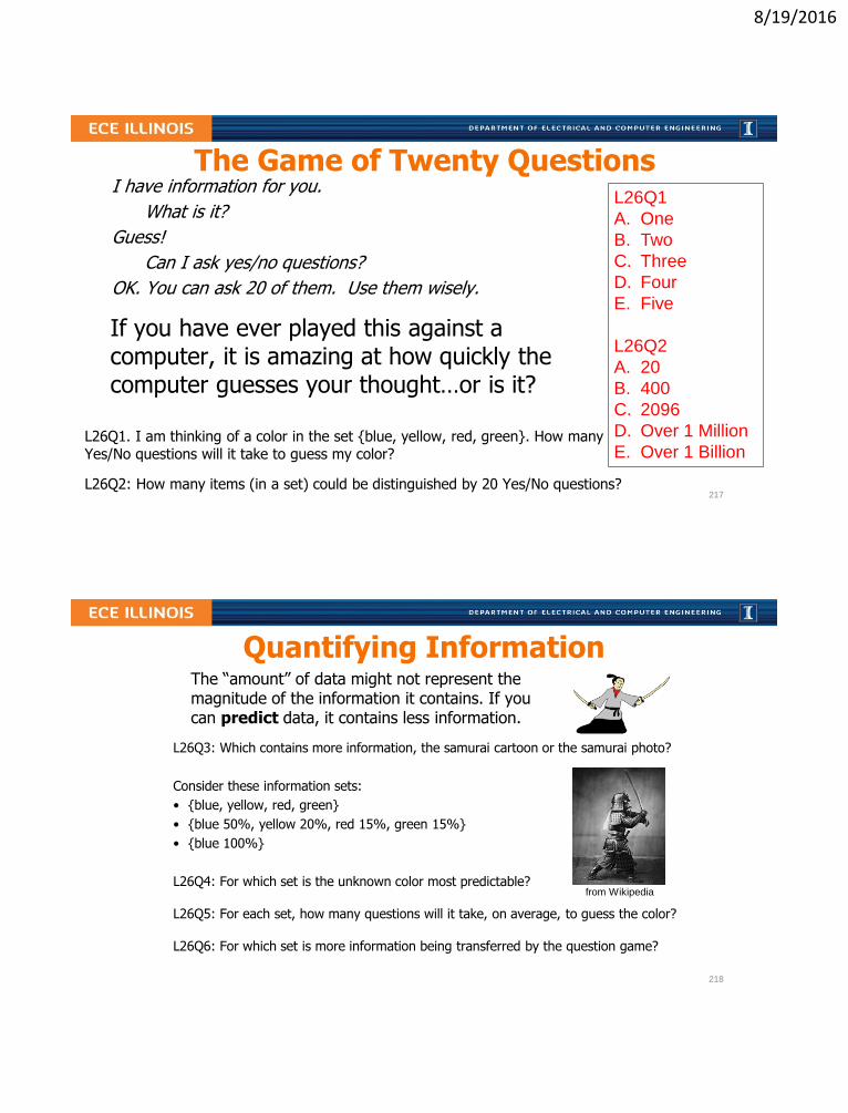
The Game of Twenty Questions
If you have ever played this against a computer, it is amazing at how quickly the computer guesses your thought…or is it?
L26Q1. I am thinking of a color in the set blue, yellow, red, green. How many Yes/No questions will it take to guess my color?
L26Q2: How many items (in a set) could be distinguished by 20 Yes/No questions?
I have information for you.
What is it?
Guess!
Can I ask yes/no questions?
OK. You can ask 20 of them. Use them wisely.
L26Q1
A. One
B. Two
C. Three
D. Four
E. Five
L26Q2
A. 20
B. 400
C. 2096
D. Over 1 Million
E. Over 1 Billion
217
Quantifying InformationThe “amount” of data might not represent the magnitude of the information it contains. If you can predict data, it contains less information.
from Wikipedia
L26Q3: Which contains more information, the samurai cartoon or the samurai photo?
Consider these information sets:
• blue, yellow, red, green
• blue 50%, yellow 20%, red 15%, green 15%
• blue 100%
L26Q4: For which set is the unknown color most predictable?
L26Q5: For each set, how many questions will it take, on average, to guess the color?
L26Q6: For which set is more information being transferred by the question game?
218

8/19/2016
Entropy measures Information
The entropy, 𝐻, of a message can be computed given the
statistical frequencies, the 𝑝𝑖 of each 𝑖𝑡ℎ possibility (a.k.a. the
probability of each message in the set of possible messages)
𝐻 =
𝑖=1
𝑁
𝑝𝑖 × − log2 𝑝𝑖 = 𝑖=1
𝑁
𝑝𝑖 × log2
1
𝑝𝑖
L26Q7: What is the entropy in a result of a single flip of a fair coin?
L26Q8: What is the entropy of a number of “heads” in two coin flips?
219
Review of logarithms and properties• Base-2 logarithm gives a power of 2 equivalent for a number:
x = log𝟐 𝑨 ⇒ 𝑨 = 𝟐𝒙
• Logarithm of an inverse of a number is negative log of the number:
log𝟐𝟏
𝑨= −log𝟐 𝑨
• Logarithm of a product is the sum of two logarithms:log𝟐 𝑨𝑩 = log𝟐 𝑨+ log𝟐𝑩
• Logarithm of a ratio is the difference of two logarithms:
log𝟐𝑨
𝑩= log𝟐 𝑨− log𝟐𝑩
𝑨 1 2 3 4 5 6 7 8 9 10 11 12 13 14 15
~log𝟐 𝑨 0.0 1.0 1.6 2.3 2.8 3.5 3.7
L26Q9: Complete the above table using logarithm properties.
L26Q10: What is log𝟐𝟐𝟒
𝟏𝟎𝟓?
220

8/19/2016
Entropy of the Class by Major
Considering only the 4 most-represented disciplines, suppose that a
selected sample of 400 ECE110 students produces the student population
shown above.
L26Q11: What is the probability that a student selected from this group is
an IE?
L26Q12: What is the entropy of any student’s department taken from this
set?
S ECE IE GE DGS
p 200/400 50/400 50/400 100/400
221
L26: Learning Objectives
a. To comparative the amount of information contained in slightly different data sets
b. To compute base-2 logarithms using log properties
c. To compute Entropy (information) in units of bits given the relative frequency of each item in a set
222

8/19/2016
Entropy of the Class by Major
Including a category of “Other”, the student population by major now takes
on the statistics shown above.
L26Q13: What is the probability that a student selected from this group is
an IE?
L26Q14: What is the entropy of any student’s department taken from this
set?
L26Q15: What would have been the entropy if all 5 categories were
equally represented by the course’s student body?
S ECE IE GE DGS Other
p 200/450 50/450 50/450 100/450 50/450
Learn It!
223
Entropy of the sum of two dice
L26Q16: What is the entropy of the sum of two dice?
L26Q17: Compare this to the entropy of one out of eleven equally-likely outcomes.
Without doing any calculations, which value should be larger (carry more information)?
1 2 3 4 5 6
1 2 3 4 5 6 7
2 3 4 5 6 7 8
3 4 5 6 7 8 9
4 5 6 7 8 9 10
5 6 7 8 9 10 11
6 7 8 9 10 11 12
S 2 3 4 5 6 7 8 9 10 11 12
p 1/36 2/36 3/36 4/36 5/36 6/36 5/36 4/36 3/36 2/36 1/36
𝐻 = 𝑖=1
𝑁
𝑝𝑖 × log2
1
𝑝𝑖
Explore More!
224

8/19/2016
L27: Compression
• Lossless vs. lossy compression
• Compression ratios and savings
• Entropy as a measurement of information
• Huffman code construction and decoding
225
Data Compression Ratio and Savings
• Data Compression Ratio (DCR)
DCR =# 𝑜𝑓 𝑏𝑖𝑡𝑠 𝑖𝑛 𝑜𝑟𝑖𝑔𝑖𝑛𝑎𝑙 𝑑𝑎𝑡𝑎
# 𝑜𝑓 𝑏𝑖𝑡𝑠 𝑖𝑛 𝑐𝑜𝑚𝑝𝑟𝑒𝑠𝑠𝑒𝑑 𝑑𝑎𝑡𝑎=𝑜𝑟𝑖𝑔𝑖𝑛𝑎𝑙 𝑑𝑎𝑡𝑎 𝑟𝑎𝑡𝑒
𝑐𝑜𝑚𝑝𝑟𝑒𝑠𝑠𝑒𝑑 𝑑𝑎𝑡𝑎 𝑟𝑎𝑡𝑒
• Savings: 𝑆 = 1 −1
𝐷𝐶𝑅(x100 for %)
L27Q1. Stereo audio is sampled at 44.1 kHz and quantized to 16
bits/channel and then compressed to 128 kbps mp3 playback format.
What are the approximate DCR and the resulting savings?
L27Q2. A picture of a samurai was saved as a 24-bit samurai.bmp (full
size, 2188 kB) and a 31 kB samurai.png. Estimate the DCR and savings
from the PNG compression.
L27Q2: DCR~
A. 10
B. 30
C. 50
D. 70
E. 100226

8/19/2016
Lossy and Lossless Compression
• Lossy Compression
– Usually leads to larger DCR and savings
– Sometimes creates noticeable “artifacts”
– Examples: mp3, mpeg, jpeg
• Lossless Compression (keeping all information)
– Uses repetition or other data statistics
– Usually leads to smaller compression ratios (~2)
– Examples: PNG, run-length codes, Huffman codes…
L27Q3. Why was the cartoon samurai picture highly compressible?
L27Q4: Can we expect to achieve such DCR with the photograph?
from Wikipedia
227
Super-Fast Sandwiches, Order-By-Number Menu
The number of orders during the lunch hour for each menu item is listed above.
L27Q5: What was the relative frequency (probability) of someone ordering the menu’s
#1 sandwich selection (we call this 𝑝1)?
L27Q6: What is the fewest number of bits needed to encode each of 8 possible orders
with a unique (and unambiguous) bit sequence for each?
L27Q7: What is the entropy of one order given the popularity statistics above?
Menu: #1 #2 #3 #4 #5
Number
of orders
18 8 9 10 5
228

8/19/2016
Huffman Codes use bits efficiently
Use fewer bits for more common symbols. Here’s how:
1. Order the symbols from most frequent on left to least frequent on right.
2. From the two least frequent symbols, create two “branches” that connect them into a single end nodes of a tree graph.
3. Mark the least frequent branch with a “0” and the most frequent a “1”
4. Consider these two symbols be one new symbol with the combined frequency. Record this new frequency of the new node and return to step 1 (or step 2), considering nodes as new symbols.
L27Q8: Create a Huffman tree based on the order statistics given above.
Menu: #1 #2 #3 #4 #5
Number
of orders
18 9 8 10 5
229
Encoding and decoding Huffman
Huffman Codes are prefix-free! (If you know where the message starts, you can separate the symbols without confusion.)
L27Q9: Complete the table above with Huffman codes from the tree above.
L27Q10: Which menu items does not appear in the sequence 111000010100?
A. #1
B. #2
C. #3
D. #4
E. #5
Menu: #1 #2 #3 #4 #5
Number
of orders
18 9 8 10 5
Huffman
Code
230

8/19/2016
Average code length is no less than entropy
Given 𝑁 symbols 𝑆1, 𝑆2, … 𝑆𝑁 and corresponding frequencies, 𝑝𝑖, the average length per symbol is
𝐿𝑎𝑣𝑔 =
𝑖=1
𝑁
𝑝𝑖 × 𝐿𝑖
𝐿𝑎𝑣𝑔 ≥ 𝐻
L27Q11: What is the average bit length per sandwich order?
L27Q12: How does the average bit length compare to entropy?
231
L27: Learning Objectives
a. Compute compression ratio and savings
b. To use relative frequency to compute entropy, the shortest theoretical average code length
c. To encode a symbol set with a Huffman code
d. To decode a Huffman-encoded message
e. To compute average code length for given a code
232

8/19/2016
Lecture 28: Photodiodes and Solar Panels
• The nature of light
• Photon absorption in semiconductors
• Photocurrent in diodes and its use
– Detecting light and signals
– Generating electrical energy
• Energy from solar panels
233
Light consists of (Energetic) Photons
• Photons are sometimes called wave packets
• Each photon carries an amount of energy given by
E(eV) = 1240/λ(nm) where 1 𝑒𝑉 = 1.6 × 10⁻¹⁹ J
• The color of light depends on its wavelength, λ
L28Q1: How many photons per second are provided by a 1 mW 650 nm laser?
234
8/19/2016
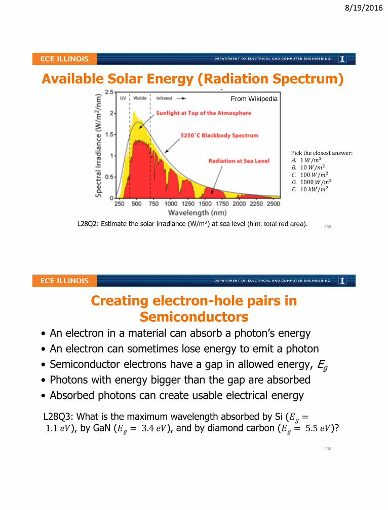
L28Q2: Estimate the solar irradiance (W/m2) at sea level (hint: total red area).
Available Solar Energy (Radiation Spectrum)
From Wikipedia
Pick the closest answer:A. 1 𝑊/𝑚2
B. 10 𝑊/𝑚2
C. 100𝑊/𝑚2
D. 1000𝑊/𝑚2
E. 10 𝑘𝑊/𝑚2
235
Creating electron-hole pairs in Semiconductors
• An electron in a material can absorb a photon’s energy
• An electron can sometimes lose energy to emit a photon
• Semiconductor electrons have a gap in allowed energy, Eg
• Photons with energy bigger than the gap are absorbed
• Absorbed photons can create usable electrical energy
L28Q3: What is the maximum wavelength absorbed by Si (𝐸𝑔 =1.1 𝑒𝑉), by GaN (𝐸𝑔 = 3.4 𝑒𝑉), and by diamond carbon (𝐸𝑔 = 5.5 𝑒𝑉)?
236

8/19/2016
Photodiode IV depends on impinging Light
• Reverse bias mode
– Photodetector
– Detecting light signals
– Energy is dissipated
• Forward bias mode
– Photovoltaic cell
– Energy is generated
I
V
L28Q4: Sparkfun’s BPW34 photodiode generates 50 μA of current when reverse-biased and illuminated with 1 mW/cm2 at 950 nm. If a 1 mW 950 nm laser is focused on the photodetector, what is the resulting photocurrent?
237
Photovoltaic operation collects Energy
• Forward-bias mode
• 𝑃 = 𝐼𝑉 is supplied
• Maximum power point
• 𝑃𝑚𝑎𝑥 = 𝐼𝑚𝑉𝑚 = 𝐹𝐹 𝐼𝑠𝑐𝑉𝑜𝑐
• Typical FF = 70%
L28Q5: Identify the 𝑃𝑚𝑎𝑥 point above
L28Q6: If Sparkfun’s BPW34 photodiode has 𝐼𝑆𝐶 = 40 𝜇𝐴 and 𝑉𝑂𝐶 =350 𝑚𝑉 when illuminated with 1 mW/cm2 at 950 nm, and the fill factor is 50%
what is the maximum power produced?
AB
C
D
E
238

8/19/2016
Solar panels as energy sources
L28Q7: Assuming 500 W/m2 solar irradiance and a 25% efficient solar panel, how much roof area should be covered to supply 50A at 120V?
L28Q8: Given an average of 5 hours of sunshine per day and a utility cost of $0.11/kWh how much of the utility cost can such a solar panel save?
ECE Spotlight…
ECEB is aspiring to a Net
Zero Energy rating and
targeting LEED Platinum
certification from the U.S.
Green Building Council.
You should look into the
project to learn how it is
being achieved. Do some
of your own number
crunching!
239
Lecture 28 Learning Objectives
a. Relate photon flux (photons/sec) to power and wavelength
b. Calculate maximum absorbed wavelength for a band gap
c. Sketch photodiode IV curve and explain operating regimes
d. Calculate reverse bias current for incident light power
e. Calculate maximum power from IV intercepts and fill factor
f. Estimate power (and its $ value) produced by a solar panel
240

8/19/2016
L29: Final Exam Review
• If you have a request that a specific question or topic be covered on this day, please email your instructor.
• Other questions will focus on muddy points.
• More info TBA.
241
242

8/19/2016
Courses Dealing with Engineering Professionalism and Ethics
• Ethics across the curriculum in electrical and computer engineering: class sessions in ECE 110, ECE 445
• Class sessions in other engineering programs: CEE 495, GE 390, MSE 201, ME 470
• CS 210, Professional and Ethical Issues in CS
• ECE/PHIL 316, Ethics and Engineering
– Elective
– Gen ed: advanced composition, humanities
243
Ethical views can have multiple origins
• Value-based
• Relationship-based
• Code-based
244

8/19/2016
What is professional responsibility?
Engineering professional responsibility encompasses the ethical obligations of engineers in their professional relationships with clients, employers, other engineers, and the public; these obligations include honesty and competence in technical work, confidentiality of proprietary information, collegiality in mentoring and peer review, and above all, the safety and welfare of the public, because engineers’ decisions can significantly affect society and the environment. –Prof. M. Loui
L4Q4: What ethical viewpoint is represented above?
A. Values B. Relationships C. Code
245
Engineers have many ethical obligations
• Relationships with clients
– Competence
– Honesty
• Relationships with employers
– Conflict of interest
– Confidentiality, e.g., trade secrets
– Individual and collective responsibility
– Loyalty, whistle-blowing
• Relationships with other professionals
– Licensing, due credit
– Collegiality, mentoring
• Relationships with the public
– Public understanding of technology
– Social impacts of technology
246

8/19/2016
IEEE Code of Ethics (2012)
We, the members of the IEEE, in recognition of the importance of our technologies in affecting the quality of life throughout the world, and in accepting a personal obligation to our profession, its members and the communities we serve, do hereby commit ourselves to the highest ethical and professional conduct and agree:
IEEE – Institute of Electrical and Electronics Engineers
247
IEEE Code of Ethics (2012)
1. to accept responsibility in making decisions consistent with the safety, health, and welfare of the public, and to disclose promptly factors that might endanger the public or the environment;
2. to avoid real or perceived conflicts of interest whenever possible, and to disclose them to affected parties when they do exist;
3. to be honest and realistic in stating claims or estimates based on available data;
4. to reject bribery in all its forms;
5. to improve the understanding of technology, its appropriate application, and potential consequences;
248

8/19/2016
IEEE Code of Ethics (2012)6. to maintain and improve our technical competence and to undertake
technological tasks for others only if qualified by training or experience, or after full disclosure of pertinent limitations;
7. to seek, accept, and offer honest criticism of technical work, to acknowledge and correct errors, and to credit properly the contributions of others;
8. to treat fairly all persons regardless of such factors as race, religion, gender, disability, age, or national origin;
9. to avoid injuring others, their property, reputation, or employment by false or malicious action;
10. to assist colleagues and co-workers in their professional developmentand to support them in following this code of ethics.
249
Case Study
Occidental Engineering…search at Santa Clara University:
http://www.scu.edu/
• Break into groups or pairs and discuss.
– Consider the issue from the viewpoint of all people involved
– Consider the options and the consequences of each
– Can your group come to a single path of action?
250