ECE-R 13 Vehicle Regulations 2004 -...
278
233 Vehicle Regulations 2004 As already known from the former handbook Legal Requirements 2000, the hand- book Vehicle Regulations 2004 shall be a simple and comfortable guideline for those readers who are frequently confronted with the national and international require- ments of braking systems. In that case the English texts of ECE-R13 as well as ECE- R13H are very help-ful. THE HANDBOOK INCLUDES: - Extracts from Legal Requirements of Road Vehicles and Braking Systems on national basis (German Road Traffic Regulations) >>> [StVZO] as of January 2003 (in German) - The Braking Directive of the Commission of the European Community in Brus- sels >>> [Directive 98/12/EC (1) ] (Adaptation Directive to 71/320/EEC) as of January 27, 1998 (in German) - The international Braking Regulation of the UNO-Economic Commission for Eu- rope in Geneva - ECE-Regulation No. 13 >>> [ECE-R13] for Road Vehicles of categories (2) M, N and O including Series 09 with the Supplements 1 to 8, whereby 8 are available as draft only. Status: August 2003 (in English) - The international Braking Regulation of the Economic Commission for Europe of the UNO in Geneva - ECE-Regulation No. 13 Harmonized >>> [ECE-R 13-H] for Road Vehicles of category(2) M 1 as of October 2002 (in English) Remark: ADR-requirements haven't been considered any more for reasons of complexity. The subject ADR (the international carriage of dangerous goods by road) - as of Jan- uary 1st, 2003 - has been revised and can be obtained under ECE/TRANS/160 (Vol.I) and ECE/TRANS/160 (Vol.II) at the UNO in Geneva or New York ( in English). (1) The Directive 98/12/EC corresponds to ECE-R13 including Series 09, without Supplements (2) The vehicle categories can be found on pages 18 and 236 The authors hope you have much fun with the new handbook! Whilst every care has been taken in the preparation and reproduction of this infor- mation, WABCO Fahrzeugsysteme GmbH make no representation or warranty as to its accuracy and cannot accept responsibility for inaccuracies or omissions or their consequences. ECE-R 13
Transcript of ECE-R 13 Vehicle Regulations 2004 -...
����� 233
Vehicle Regulations 2004As already known from the former handbook Legal Requirements 2000, the hand-book Vehicle Regulations 2004 shall be a simple and comfortable guideline for thosereaders who are frequently confronted with the national and international require-ments of braking systems. In that case the English texts of ECE-R13 as well as ECE-R13H are very help-ful.
THE HANDBOOK INCLUDES:- Extracts from Legal Requirements of Road Vehicles and Braking Systems on
national basis (German Road Traffic Regulations) >>> [StVZO] as of January2003 (in German)
- The Braking Directive of the Commission of the European Community in Brus-sels >>> [Directive 98/12/EC(1)] (Adaptation Directive to 71/320/EEC) as of January 27, 1998 (in German)
- The international Braking Regulation of the UNO-Economic Commission for Eu-rope in Geneva - ECE-Regulation No. 13 >>> [ECE-R13] for Road Vehicles ofcategories(2) M, N and O including Series 09 with the Supplements 1 to 8,whereby 8 are available as draft only. Status: August 2003 (in English)
- The international Braking Regulation of the Economic Commission for Europe ofthe UNO in Geneva - ECE-Regulation No. 13 Harmonized >>> [ECE-R 13-H] forRoad Vehicles of category(2) M1 as of October 2002 (in English)
Remark:ADR-requirements haven't been considered any more for reasons of complexity.The subject ADR (the international carriage of dangerous goods by road) - as of Jan-uary 1st, 2003 - has been revised and can be obtained under ECE/TRANS/160(Vol.I) and ECE/TRANS/160 (Vol.II) at the UNO in Geneva or New York ( in English).
(1) The Directive 98/12/EC corresponds to ECE-R13 including Series 09,without Supplements
(2) The vehicle categories can be found on pages 18 and 236
The authors hope you have much fun with the new handbook!Whilst every care has been taken in the preparation and reproduction of this infor-mation, WABCO Fahrzeugsysteme GmbH make no representation or warranty asto its accuracy and cannot accept responsibility for inaccuracies or omissions ortheir consequences.
ECE-R 13
�����234
The explanations, interpretations and summaries are presented in good faith but areintended as guidelines only and should not be applied without reference to the latestofficial text of the relevant regulations.
ECE-R 13
����� 235
ECE-R 13
ECE - Regulation No. 13

�����236
CLASSIFICATION AND DEFINITION OF POWER-DRIVEN VEHICLES AND TRAILERS
Category M: Motor vehicles having at least four wheels, or having threewheels when the maximum weight exceeds 1 metric ton, andused for the carriage of passengers.
Category M1: Vehicles used for the carriage of passengers and comprising notmore than eight seats in addition to the driver’s seat.
Category M2: Vehicles used for the carriage of passengers, comprising morethan eight seats in addition to the driver’s seat, and having amaximum weight not exceeding 5 metric tons.
Category M3: Vehicles used for the carriage of passengers, comprising morethan eight seats in addition to the driver’s seat, and having amaximum weight exceeding 5 metric tons.
Category N: Motor vehicles having at least four wheels, or having threewheels when the maximum weight exceeds 1 metric ton, andused for the carriage of goods.
Category N1: Vehicles used for the carriage of goods and having a maximumweight not exceeding 3.5 metric tons.
Category N2: Vehicles used for the carriage of goods and having a maximumweight exceeding 3.5 but not exceeding 12 metric tons.
Category N3: Vehicles used for the carriage of goods and having a maximumweight exceeding 12 metric tons.
ECE-R 13

����� 237
Category O: Trailers (including semi-trailers)
Category O1: Trailers with a maximum weight not exceeding 0.75 metric ton
Category O2: Trailers with a maximum weight exceeding 0.75 metric ton but notexceeding 3.5 metric tons.
Category O3: Trailers with a maximum weight exceeding 3.5 but not exceeding10 metric tons.
Category O4: Trailers with a maximum weight exceeding 10 metric tons.
ECE-R 13

�����238
E/ECE/324E/ECE/TRANS/505 Rev. 1/Add. 12/Rev. 4 + ...
AGREEMENT
CONCERNING THE ADOPTION OF UNIFORM TECHNICAL PRESCRIPTIONS FOR WHEELED VEHICLES, EQUIPMENT AND
PARTS WHICH CAN BE FITTED AND/OR BE USED ON WHEELED VEHICLES AND THE CONDITIONS FOR RECIPROCAL
RECOGNITION OF APPROVAL GRANTED ON THE BASIS OF THESE PRESCRIPTIONS * 1)
Addendum 12: Regulation No. 13
Revision 4
Incorporating:
01 series of amendments - Date of entry into force: 29 August 197302 series of amendments - Date of entry into force: 11 July 197403 series of amendments - Date of entry into force: 4 January 197904 series of amendments - Date of entry into force: 11 August 198105 series of amendments - Date of entry into force: 26 November 1984Supplement 1 to 05 series of amendments Date of entry into force: 1 April 1987Supplement 2 to 05 series of amendments Date of entry into force: 5 October 1987Supplement 3 to 05 series of amendments Date of entry into force: 29 July 1988
ECE-R 13
*1) Former title of the Agreement:Agreement Concerning the Adoption of Uniform Conditions of Approval and Reciprocal Recognition of Approval for Motor Vehicle Equipment and Parts, done at Geneva on 20 March 1958.

����� 239
06 series of amendments - Date of entry into force: 22 November 1990Supplement 1 to 06 series of amendments Date of entry into force: 15 November 1992Supplement 2 to 06 series of amendments Date of entry into force: 24 August 199307 series of amendments - Date of entry into force: 18 September 199408 series of amendments - Date of entry into force: 26 March 1995Supplement 1 to 08 series of amendments Date of entry into force: 28 August 199609 series of amendments - Date of entry into force: 28 August 1996Supplement 1 to 09 series of amendments Date of entry into force: 15 January 1997Supplement 2 to 09 series of amendments Date of entry into force: 22 February 1997Corr. 1 to 09 series of amendments Date of entry into force: 12 March 1997Corr. 1 to Supplemend 2 to 09 series of amendments Date of entry into force: 12 March 1997Corr. 2 to 09 series of amendments Date of entry into force: 23 June 1997Corr. 1 to Revision 3Date of entry into force: 23 June 1997Corr. 2 to Revision 3Supplement 3 to 09 series of amendments Date of entry into force: 27 April 1998Supplement 4 to 09 series of amendments Date of entry into force: 04 February 1999Supplement 5 to 09 series of amendments Date of entry into force: 27 December 2000Supplement 6 to 09 series of amendments Date of entry into force: 14 April 2001Supplement 7 to 09 series of amendments Date of entry into force: 30 January 2003Supplement 8 to 09 series of amendments adapted by WP 29
ECE-R 13

�����240
ECE-R 13 Title pageRegulation Uniform provisions concerning the approval of vehicles
of categories M, N and O with regard to braking243
Annex 1: Braking equipment, devices, methods and conditions not covered by this Regulation
289
Annex 2: Communication 289
Annex 2 -Appendix 1
List of vehicle data for the purpose of Regulation No. 90 approvals
295
Annex 2 -Appendix 2
Type approval certificate concerning the vehicle braking equipment
297
Annex 3: Arrangements of approval marks 298
Annex 4: Braking tests and performance of braking systems 300
Annex 4 -Appendix 1
Procedure for monitoring the state of battery charge
321
Annex 5: Additional provisions applicable to certain vehicles as specified in the ADR *)
322
Annex 6: Method of measuring the response time on vehiclesequipped with compressed-air braking systems
324
Annex 6 -Appendix
Example of a simulator 329
Annex 7: Provisions relating to energy sources and energy storage devices (Energy accumulators)
331
Annex 8: Provisions relating to specific conditions for spring braking systems
339
Annex 9: Provisions relating to parking braking systems equipped with a mechanical brake cylinder locking device (Lock actuators)
343
Annex 10: Distribution of braking among the axles of vehicles and requirements for compatibility between towing vehicles and trailers
345
ECE-R 13 Table of Contents
*) European Agreement concerning the International Carriage of DangerousGoods by Road.
����� 241
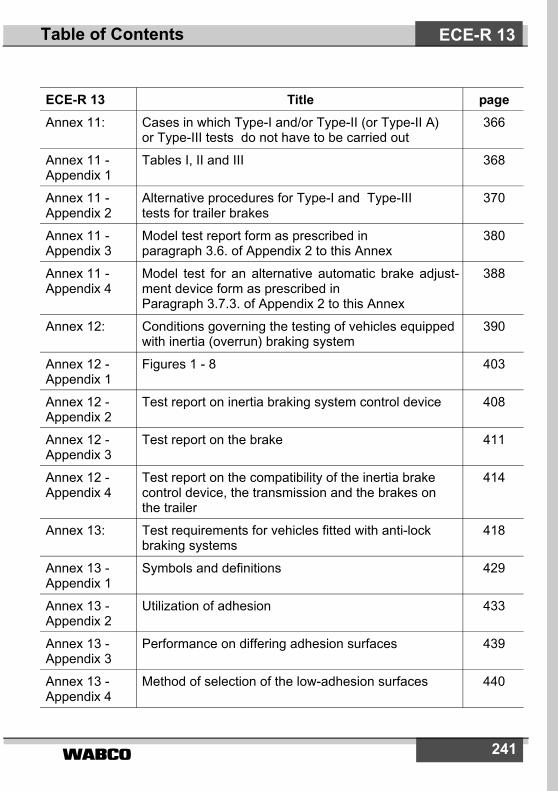
ECE-R 13 Title pageAnnex 11: Cases in which Type-I and/or Type-II (or Type-II A)
or Type-III tests do not have to be carried out366
Annex 11 -Appendix 1
Tables I, II and III 368
Annex 11 -Appendix 2
Alternative procedures for Type-I and Type-III tests for trailer brakes
370
Annex 11 -Appendix 3
Model test report form as prescribed in paragraph 3.6. of Appendix 2 to this Annex
380
Annex 11 -Appendix 4
Model test for an alternative automatic brake adjust-ment device form as prescribed in Paragraph 3.7.3. of Appendix 2 to this Annex
388
Annex 12: Conditions governing the testing of vehicles equippedwith inertia (overrun) braking system
390
Annex 12 -Appendix 1
Figures 1 - 8 403
Annex 12 -Appendix 2
Test report on inertia braking system control device 408
Annex 12 -Appendix 3
Test report on the brake 411
Annex 12 -Appendix 4
Test report on the compatibility of the inertia brake control device, the transmission and the brakes on the trailer
414
Annex 13: Test requirements for vehicles fitted with anti-lock braking systems
418
Annex 13 -Appendix 1
Symbols and definitions 429
Annex 13 -Appendix 2
Utilization of adhesion 433
Annex 13 -Appendix 3
Performance on differing adhesion surfaces 439
Annex 13 -Appendix 4
Method of selection of the low-adhesion surfaces 440
ECE-R 13Table of Contents
�����242
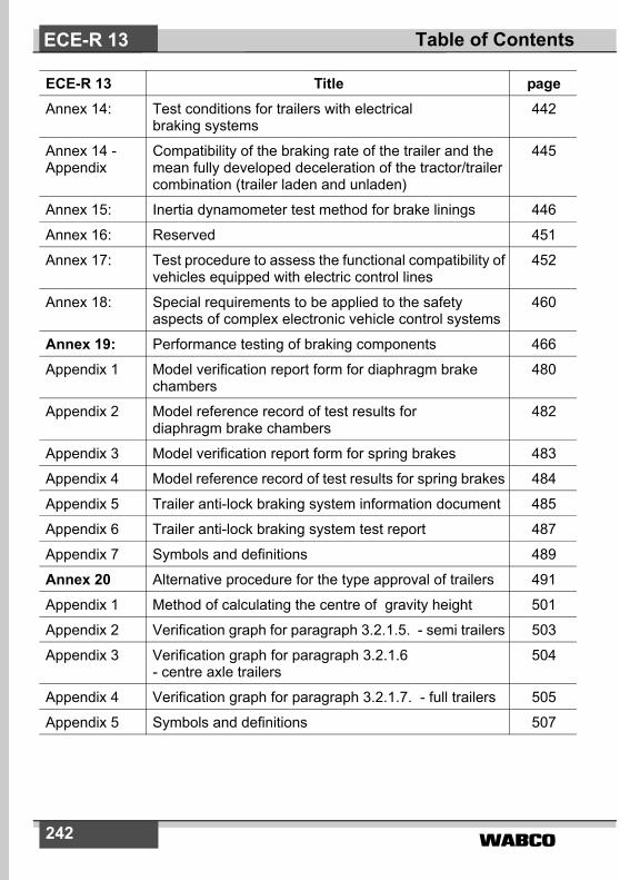
ECE-R 13 Title pageAnnex 14: Test conditions for trailers with electrical
braking systems442
Annex 14 -Appendix
Compatibility of the braking rate of the trailer and themean fully developed deceleration of the tractor/trailercombination (trailer laden and unladen)
445
Annex 15: Inertia dynamometer test method for brake linings 446
Annex 16: Reserved 451
Annex 17: Test procedure to assess the functional compatibility ofvehicles equipped with electric control lines
452
Annex 18: Special requirements to be applied to the safety aspects of complex electronic vehicle control systems
460
Annex 19: Performance testing of braking components 466
Appendix 1 Model verification report form for diaphragm brakechambers
480
Appendix 2 Model reference record of test results for diaphragm brake chambers
482
Appendix 3 Model verification report form for spring brakes 483
Appendix 4 Model reference record of test results for spring brakes 484
Appendix 5 Trailer anti-lock braking system information document 485
Appendix 6 Trailer anti-lock braking system test report 487
Appendix 7 Symbols and definitions 489
Annex 20 Alternative procedure for the type approval of trailers 491
Appendix 1 Method of calculating the centre of gravity height 501
Appendix 2 Verification graph for paragraph 3.2.1.5. - semi trailers 503
Appendix 3 Verification graph for paragraph 3.2.1.6 - centre axle trailers
504
Appendix 4 Verification graph for paragraph 3.2.1.7. - full trailers 505
Appendix 5 Symbols and definitions 507
ECE-R 13 Table of Contents

����� 243
Regulation No. 13UNlFORM PROVISIONS CONCERNING THE APPROVAL OF
VEHICLES OF CATEGORIES M, N AND O WITH REGARD TO BRAKING
1. SCOPE1.1. This Regulation applies to the braking of power-driven vehicles
individually and of trailers individually of categories M, N and O asdefined in annex 7 to the Consolidated Resolution on theConstruction of Vehicles (R.E.3). *)
1.2. This Regulation does not cover:1.2.1. vehicles with a design speed not exceeding 25 km/h;1.2.2. trailers which may not be coupled to power-driven vehicles with a
design speed exceeding 25 km/h;1.2.3. vehicles fitted for invalid drivers.1.3. Subject to the applicable provisions of this Regulation, the
equipment, devices, methods and conditions enumerated in annex 1are not covered by this Regulation.
2. DEFINITlONSFor the purposes of this Regulation,
2.1. ”Approval of a vehicle“ means the approval of a vehicle type withregard to braking.
2.2. ”Vehicle type“ means a category of vehicles which do not differ insuch essential respects as:
2.2.1. in the case of power-driven vehicles,2.2.1.1. the vehicle category (see paragraph 1.1. above);2.2.1.2. the maximum mass, as defined in paragraph 2.16. below;2.2.1.3. the distribution of mass among the axles;2.2.1.4. the maximum design speed;2.2.1.5. A different type of braking equipment, with more particular reference
to the presence or otherwise of equipment for braking a trailer, or anypresence of an electric regenerative braking system;
ECE-R 13Regulation
*) An alternative set of requirements for category M1 vehicles is offered in Reg-ulation No. 13-H. Contracting Parties that are signatories both to RegulationNo. 13-H and this Regulation recognize approvals to either Regulation asequally valid.
�����244
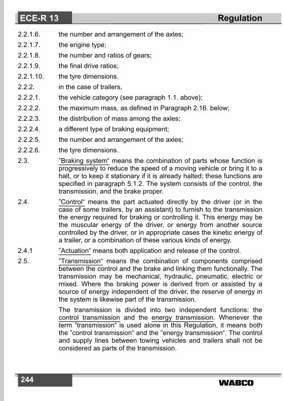
2.2.1.6. the number and arrangement of the axles;2.2.1.7. the engine type;2.2.1.8. the number and ratios of gears;2.2.1.9. the final drive ratios;2.2.1.10. the tyre dimensions.2.2.2. in the case of trailers,2.2.2.1. the vehicle category (see paragraph 1.1. above);2.2.2.2. the maximum mass, as defined in Paragraph 2.16. below;2.2.2.3. the distribution of mass among the axles;2.2.2.4. a different type of braking equipment;2.2.2.5. the number and arrangement of the axles;2.2.2.6. the tyre dimensions.2.3. ”Braking system“ means the combination of parts whose function is
progressively to reduce the speed of a moving vehicle or bring it to ahalt, or to keep it stationary if it is already halted; these functions arespecified in paragraph 5.1.2. The system consists of the control, thetransmission, and the brake proper.
2.4. ”Control“ means the part actuated directly by the driver (or in thecase of some trailers, by an assistant) to furnish to the transmissionthe energy required for braking or controlling it. This energy may bethe muscular energy of the driver, or energy from another sourcecontrolled by the driver, or in appropriate cases the kinetic energy ofa trailer, or a combination of these various kinds of energy.
2.4.1 ”Actuation“ means both application and release of the control.2.5. ”Transmission“ means the combination of components comprised
between the control and the brake and linking them functionally. Thetransmission may be mechanical, hydraulic, pneumatic, electric ormixed. Where the braking power is derived from or assisted by asource of energy independent of the driver, the reserve of energy inthe system is likewise part of the transmission.The transmission is divided into two independent functions: thecontrol transmission and the energy transmission. Whenever theterm ”transmission“ is used alone in this Regulation, it means boththe ”control transmission“ and the ”energy transmission“. The controland supply lines between towing vehicles and trailers shall not beconsidered as parts of the transmission.
ECE-R 13 Regulation
����� 245
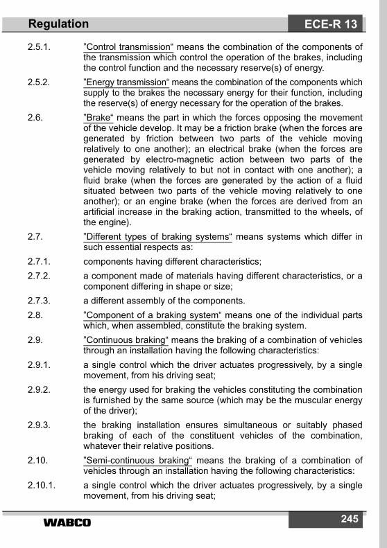
2.5.1. ”Control transmission“ means the combination of the components ofthe transmission which control the operation of the brakes, includingthe control function and the necessary reserve(s) of energy.
2.5.2. ”Energy transmission“ means the combination of the components whichsupply to the brakes the necessary energy for their function, includingthe reserve(s) of energy necessary for the operation of the brakes.
2.6. ”Brake“ means the part in which the forces opposing the movementof the vehicle develop. It may be a friction brake (when the forces aregenerated by friction between two parts of the vehicle movingrelatively to one another); an electrical brake (when the forces aregenerated by electro-magnetic action between two parts of thevehicle moving relatively to but not in contact with one another); afluid brake (when the forces are generated by the action of a fluidsituated between two parts of the vehicle moving relatively to oneanother); or an engine brake (when the forces are derived from anartificial increase in the braking action, transmitted to the wheels, ofthe engine).
2.7. ”Different types of braking systems“ means systems which differ insuch essential respects as:
2.7.1. components having different characteristics;2.7.2. a component made of materials having different characteristics, or a
component differing in shape or size;2.7.3. a different assembly of the components.2.8. ”Component of a braking system“ means one of the individual parts
which, when assembled, constitute the braking system.2.9. ”Continuous braking“ means the braking of a combination of vehicles
through an installation having the following characteristics:2.9.1. a single control which the driver actuates progressively, by a single
movement, from his driving seat;2.9.2. the energy used for braking the vehicles constituting the combination
is furnished by the same source (which may be the muscular energyof the driver);
2.9.3. the braking installation ensures simultaneous or suitably phasedbraking of each of the constituent vehicles of the combination,whatever their relative positions.
2.10. ”Semi-continuous braking“ means the braking of a combination ofvehicles through an installation having the following characteristics:
2.10.1. a single control which the driver actuates progressively, by a singlemovement, from his driving seat;
ECE-R 13Regulation

�����246
2.10.2. the energy used for braking the vehicles constituting the combinationis furnished by two different sources (one of which may be themuscular energy of the driver);
2.10.3. the braking installation ensures simultaneous or suitably phasedbraking of each of the constituent vehicles of the combination,whatever their relative positions.
2.11. ”Automatic braking“ means braking of the trailer or trailers occurringautomatically in the event of separation of components of thecombination of coupled vehicles, including such separation throughthe breakage of a coupling, the effectiveness of the braking of theremainder of the combination not being thereby destroyed.
2.12. ”Inertia (or overrun) braking“ means braking by utilizing the forcesgenerated by the trailer's moving up on the towing vehicle.
2.13. ”Progressive and graduated braking“ means braking during which,within the normal operating range of the equipment, and duringactuation of the brakes (see paragraph 2.21. below);
2.13.1. the driver can at any moment increase or decrease the braking forceby acting on the control;
2.13.2. the braking force varies proportionally as the action on the control(monotonic function); and
2.13.3. the braking force can be easily regulated with sufficient precision.2.14. ”Phased braking“ is a means which may be used where two or more
sources of braking are operated from a common control, wherebyone source may be given priority by phasing back the other source(s)so as to make increased control movement necessary before theybegin to be brought into operation.
2.15. ”Endurance braking system“ means an additional braking systemhaving the capability to provide and to maintain a braking effect overa long period of time without a significant reduction in performance.The term ”endurance braking system“ covers the complete systemincluding the control device,
2.15.1. The endurance braking system may comprise a single device or acombination of several devices. Each device may have its owncontrol.
2.15.2. Control configurations for endurance braking systems:2.15.2.1. ”Independent endurance braking system“ means a endurance
braking system whose control device is separated from that of theservice and other braking systems,
ECE-R 13 Regulation

����� 247
2.15.2.2. ”Integrated endurance braking system“ means a endurance brakingsystem whose control device is integrated with that of the servicebraking system in such a way that both endurance braking systemand service braking systems are applied simultaneously or suitablyphased by operation of the combined control device;
2.15.2.3. ”Combined endurance braking system“ means an integratedendurance braking system, which in addition has a cut-out device,which allows the combined control to apply the service brakingsystem alone.
2.16. ”Laden vehicle” means, except where otherwise stated, a vehicle soladen as to attain its ”maximum mass“.
2.17. ”Maximum mass“ means the maximum mass stated by the vehiclemanufacturer to be technically permissible (this mass may be higherthan the ”permissible maximum mass“ laid down by the nationaladministration).
2.18. ”The distribution of mass among the axles“ means the distribution ofthe effect of the gravity on the mass of the vehicle and/or its contentsamong the axles.
2.19. ”Wheel/axle load“ means the vertical static reaction (force) of theroad surface in the contact area on the wheel/wheels of the axle.
2.20. ”Maximum stationary wheel/axle load“ means the stationary wheel/axle load achieved under the condition of the laden vehicle.
2.21. ”Electric regenerative braking“ means a braking system which, duringdeceleration, provides for the conversion of vehicle kinetic energyinto electrical energy.
2.21.1. ”Electric regenerative braking control“ means a device whichmodulates the action of the electric regenerative braking system;
2.21.2. ”Electric regenerative braking system of category A“ means anelectric regenerative braking system which is not part of the servicebraking system;
2.21.3. ”Electric regenerative braking systems of category B“ means anelectric regenerative braking system which is part of the servicebraking system;
2.21.4. ”Electric state of charge“ means the instantaneous ratio of electricquantity of energy stored in the traction battery relative to themaximum quantity of electric energy which could be stored in thisbattery;
ECE-R 13Regulation

�����248
2.21.5. ”Traction battery“ means an assembly of accumulators constitutingthe storage of energy used for powering the traction motor(s) of thevehicle.
2.22. ”Hydraulic braking system with stored energy“ means a brakingsystem where energy is supplied by a hydraulic fluid under pressure,stored in one or more accumulators fed from one or more pressurepumps, each fitted with a means of limiting the pressure to amaximum value. This value shall be specified by the manufacturer.
2.23. ”Simultaneous lockup of the front and rear wheels“ refers to thecondition when the time interval between the first occurrence oflockup of the last (second) wheel on the rear axle and the firstoccurrence of lockup on the last (second) wheel on the front axle isless than 0.1 second.
2.24. ”Electric control line“ means the electrical connection betweenpower-driven vehicle and trailer which provides the braking controlfunction to the trailer. It comprises the electrical wiring and connectorand includes the parts for data communication and the electricalenergy supply for the trailer control transmission.
2.25. ”Data communication“ means the transfer of digital data under therules of a protocol.
2.26. ”Point-to-point“ means a topology of a communication network withonly two units. Each unit has an integrated termination resistor for thecommunication line.
2.27. ”Coupling force control“ means a system / function to balanceautomatically the braking rate of towing vehicle and trailer.
2.28. ”Nominal value“ definitions for braking reference performance arerequired to put a value on the transfer function of the braking system,relating output to input for vehicles individually and when used incombination.
2.28.1. ”Nominal value“ is defined, for a power-driven vehicle, as thecharacteristic which can be demonstrated at Type Approval andwhich relates the braking rate of the vehicle on its own to the level ofthe braking input variable.
2.28.2. ”Nominal value“ is defined, for a trailer, as the characteristic whichcan be demonstrated at Type Approval and which relates the brakingrate to the coupling head signal.
2.28.3. ”Nominal demand value“ is defined, for coupling force control, as thecharacteristic which relates the coupling head signal to the brakingrate and which can be demonstrated at Type Approval, within thelimits of the compatibility bands of annex 10.
ECE-R 13 Regulation

����� 249
2.29. ”Automatically commanded braking“ means a function within acomplex electronic control system where actuation of the brakingsystem(s) or brakes of certain axles is made for the purpose ofgenerating vehicle retardation with or without a direct action of thedriver, resulting from the automatic evaluation of on-board initiatedinformation.
2.30. ”Selective braking“ means actuation of individual brake(s) byautomatic means in which vehicle retardation is secondary to vehiclebehaviour modification.
2.31. ”Reference braking forces“ means the braking forces of one axlegenerated at the circumference of the tyre on a roller brake tester,relative to brake actuator pressure and declared at the time of typeapproval.
3. APPLICATION FOR APPROVAL3.1. The application for approval of a vehicle type with regard to braking
shall be submitted by the vehicle manufacturer or by his dulyaccredited representative.
3.2. It shall be accompanied by the undermentioned documents intriplicate and by the following particulars:
3.2.1. a description of the vehicle type with regard to the items specified inparagraph 2.2. above. The numbers and/or symbols identifying thevehicle type and, in the case of power-driven vehicles, the enginetype shall be specified;
3.2.2. a list of the components, duly identified, constituting the brakingequipment;
3.2.3. a diagram of assembled braking equipment and an indication of theposition of its components on the vehicle;
3.2.4. detailed drawings of each component to enable it to be easily locatedand identified.
3.3. A vehicle, representative of the vehicle type to be approved, shall besubmitted to the Technical Service conducting the approval tests.
3.4. The competent authority shall verify the existence of satisfactoryarrangements for ensuring effective control of the conformity ofproduction before type approval is granted.
4. APPROVAL4.1. If the vehicle type submitted for approval pursuant to this Regulation
meets the requirements of paragraphs 5. and 6. below, approval ofthat vehicle type shall be granted.
ECE-R 13Regulation
�����250
4.2. An approval number shall be assigned to each type approved, its firsttwo digits (at present 09) shall indicate the series of amendmentsincorporating the most recent major technical amendments made tothe Regulation at the time of issue of the approval. The sameContracting Party shall not assign the same number to the samevehicle type equipped with another type of braking system, or toanother vehicle type.
4.3. Notice of approval or of refusal of approval of a vehicle type pursuantto this Regulation shall be communicated to the Parties to theAgreement which apply this Regulation by means of a form conformingto the model in annex 2 to this Regulation and of a summary of theinformation contained in the documents referred to in paragraphs3.2.1. to 3.2.4. above, the drawings supplied by the applicant forapproval being in a format not exceeding A 4 (210 x 297 mm), orfolded to that format, and on an appropriate scale.
4.4. There shall be affixed, conspicuously and in a readily accessibleplace specified on the approval form, to every vehicle conforming toa vehicle type approved under this Regulation, an internationalapproval mark consisting of:
4.4.1. a circle surrounding the letter ”E“ followed by the distinguishingnumber of the country which has granted approval, 1) and
ECE-R 13 Regulation
1) 1 for Germany, 2 for France, 3 for Italy, 4 for the Netherlands, 5 for Sweden,6 for Belgium, 7 for Hungary, 8 for the Czech Republic, 9 for Spain, 10 forYugoslavia, 11 for the United Kingdom, 12 for Austria, 13 for Luxembourg,14 for Switzerland, 15 (vacant), 16 for Norway, 17 for Finland, 18 for Den-mark, 19 for Romania, 20 for Poland, 21 for Portugal, 22 for the RussianFederation, 23 for Greece, 24 for Ireland, 25 for Croatia, 26 for Slovenia, 27for Slovakia, 28 for Belarus, 29 for Estonia, 30 (vacant), 31 for Bosnia andHerzegovina, 32 for Latvia, 33 (vacant), 34 for Bulgaria, 35-36 (vacant), 37for Turkey, 38-39 (vacant), 40 for the former Yugoslav Republic of Macedo-nia, 41 (vacant), 42 for the European Community (Approvals are granted byits Member States using their respective ECE symbol), 43 for Japan, 44(vacant), 45 for Australia, 46 for Ukraine and 47 for South Africa. Subse-quent numbers shall be assigned to other countries in the chronologicalorder in which they ratify or accede to the Agreement Concerning the Adop-tion of Uniform Technical Prescriptions for Wheeled Vehicles, Equipmentand Parts which can be Fitted and/or be Used on Wheeled Vehicles and theConditions for Reciprocal Recognition of Approvals Granted on the Basis ofthese Prescriptions, and the numbers thus assigned shall be communicatedby the Secretary-General of the United Nations to the Contracting Parties tothe Agreement.

251
4.4.2. the number of this Regulation, followed by the letter ”R“, a dash andthe approval number to the right of the circle prescribed in paragraph4.4.1. above.
4.5. However, if a vehicle of categories M2 or M3 has been approvedpursuant to the provisions of annex 4, paragraph 1.8. to thisRegulation, the number of the Regulation shall be followed by theletter M.
4.6. If the vehicle conforms to a vehicle type approved under one or moreother Regulations, annexed to the Agreement, in the country whichhas granted approval under this Regulation, the symbol prescribed inparagraph 4.4.1. need not be repeated; in such a case, theRegulation and approval numbers and the additional symbols of allthe Regulations under which approval has been granted in thecountry which has granted approval under this Regulation shall beplaced in vertical columns to the right of the symbol prescribed inparagraph 4.4.1. above.
4.7. The approval mark shall be clearly legible and be indelible.4.8. The approval mark shall be placed close to or on the vehicle data plate.4.9. Annex 3 to this Regulation gives examples of arrangements of
approval marks.
5. SPECIFICATIONS5.1. General5.1.1. Braking system5.1.1.1. The braking system shall be so designed, constructed and fitted as to
enable the vehicle in normal use, despite the vibration to which it maybe subjected, to comply with the provisions of this Regulation.
5.1.1.2. In particular, the braking system shall be so designed, constructedand fitted as to be able to resist the corroding and ageing phenomenato which it is exposed.
5.1.1.3. Brake linings shall not contain asbestos.5.1.1.4. The effectiveness of the braking systems, including the electric
control line, shall not be adversely affected by magnetic or electricalfields. This shall be demonstrated by compliance with Regulation No.10, 02 series of amendments. *)
5.1.1.5. A failure detection signal may interrupt momentarily (< 10 ms) the
ECE-R 13Regulation
*) European Communities Council Directive 72/245/EEC, as revised by Direc-tive 95/54/EC.

252
demand signal in the control transmission, provided that the brakingperformance is thereby not reduced.
5.1.2. Functions of the braking systemThe braking system defined in Paragraph 2.3. of this Regulation mustfulfil the following functions:
5.1.2.1. Service braking systemThe service braking system must make it possible to control themovement of the vehicle and to halt it safely, speedily and effectively,whatever its speed and load, on any up or down gradient. It must bepossible to graduate this braking action. The driver must be able toachieve this braking action from his driving seat without removing hishands from the steering control.
5.1.2.2. Secondary braking systemThe secondary braking system must make it possible to halt thevehicle within a reasonable distance in the event of failure of theservice braking system. It must be possible to graduate this brakingaction. The driver must be able to obtain this braking action from hisdriving seat while keeping at least one hand on the steering control.For the purposes of these provisions it is assumed that not more thanone failure of the service braking system can occur at one time.
5.1.2.3. Parking braking systemThe parking braking system must make it possible to hold the vehiclestationary on an up or down gradient even in the absence of thedriver, the working parts being then held in the locked position by apurely mechanical device. The driver must be able to achieve thisbraking action from his driving seat, subject, in the case of a trailer, tothe provisions of paragraph 5.2.2.10. of this Regulation. The trailerair brake and the parking braking system of the towing vehicle maybe operated simultaneously provided that the driver is able to check,at any time, that the parking brake performance of the vehiclecombination, obtained by the purely mechanical action of the parkingbraking system, is sufficient.
5.1.3. Connections, for compressed-air braking systems, between power-driven vehicles and trailers;
5.1.3.1. The connections of the compressed-air braking systems betweenpower-driven vehicles and trailers shall be provided according toparagraphs 5.1.3.1.1., 5.1.3.1.2. or 5.1.3.1.3.:
5.1.3.1.1. One pneumatic supply line and one pneumatic control line;5.1.3.1.2. One pneumatic supply line, one pneumatic control line and one
electric control line;
ECE-R 13 Regulation

����� 253
5.1.3.1.3. One pneumatic supply line and one electric control line; this option issubject to footnote. 2)
5.1.3.2. The electric control line of the power-driven vehicle shall provideinformation as to whether the requirements of paragraph 5.2.1.18.2.can be satisfied by the electric control line, without assistance fromthe pneumatic control line. It shall also provide information as towhether it is equipped according to paragraph 5.1.3.1.2. with twocontrol lines or according to paragraph 5.1.3.1.3. with only an electriccontrol line.
5.1.3.3. A power-driven vehicle equipped according to paragraph 5.1.3.1.3.shall recognize that the coupling of a trailer equipped according toparagraph 5.1.3.1.1. is not compatible. When such vehicles areelectrically connected via the electric control line of the towingvehicle, the driver shall be warned by the red optical warning signalspecified in paragraph 5.2.1.29.1.1. and when the system isenergized, the brakes on the towing vehicle shall be automaticallyapplied. This brake application shall provide at least the prescribedparking braking performance required by paragraph 2.3.1. of annex 4to this Regulation.
5.1.3.4. In the case of a power-driven vehicle equipped with two control linesas defined in paragraph 5.1.3.1.2., when electrically connected to atrailer which is also equipped with two control lines, the followingprovisions shall be fulfilled:
5.1.3.4.1. both signals shall be present at the coupling head and the trailer shalluse the electric control signal unless this signal is deemed to havefailed. In this case the trailer shall automatically switch to thepneumatic control line;.
5.1.3.4.2. each vehicle shall conform to the relevant provisions of annex 10 tothis Regulation for both electric and pneumatic control lines; and
5.1.3.4.3. when the electric control signal has exceeded the equivalent of 1 barfor more than 1 second, the trailer shall verify that a pneumatic signalis present; should no pneumatic signal be present, the driver shall bewarned from the trailer by the separate yellow warning signalspecified in paragraph 5.2.1.29.2. below.
5.1.3.5. A trailer may be equipped as defined in paragraph 5.1.3.1.3.,provided that it can only be operated in conjunction with a power-driven vehicle with an electric control line which satisfies the
ECE-R 13Regulation
2) Until uniform technical standards have been agreed, which ensure compati-bility and safety, connections between power-driven vehicles and trailersconforming to paragraph 5.1.3.1.3. shall not be permitted.

�����254
requirements of paragraph 5.2.1.18.2. In any other case, the trailer,when electrically connected, shall automatically apply the brakes orremain braked. The driver shall be warned by the separate yellowwarning signal specified in paragraph 5.2.1.28.2.
5.1.3.6. The electric control line shall conform to ISO 11992-1 and 11992-2:2003 and be a point-to-point type using the seven pin connectoraccording to ISO 7638-1 or 7638-2:1997. The data contacts of theISO 7638 connector shall be used to transfer information exclusivelyfor braking (including ABS) and running gear (steering, tyres andsuspension) functions as specified in ISO 11992-2:2003. The brakingfunctions have priority and shall be maintained in the normal andfailed modes. The transmission of running gear information shall notdelay the braking functions. The power supply, provided by the ISO7638 connector, shall be used exclusively for braking and runninggear functions and that required for the transfer of trailer relatedinformation not transmitted via the electric control line. However, in allcases the provisions of paragraph 5.2.2.18. of this Regulation shallapply. The power supply for other functions shall use othermeasures.
5.1.3.6.1. The functional compatibility of towing and towed vehicles equippedwith electric control lines as defined above shall be assessed at thetime of type approval by checking that the relevant provisions of ISO11992:2003 parts 1 and 2 are fulfilled. Annex 17 of this Regulationprovides an example of tests that may be used to perform thisassessment.
5.1.3.6.2. When a power-driven vehicle is equipped with an electric control lineand electrically connected to a trailer equipped with an electriccontrol line, a continuous failure (> 40 ms) within the electric controlline shall be detected in the power-driven vehicle and shall besignalled to the driver by the yellow warning signal specified inparagraph 5.2.1.29.1.2., when such vehicles are connected via theelectric control line.
5.1.3.7. If the operation of the parking braking system on the power-drivenvehicle also operates a braking system on the trailer, as permitted byparagraph 5.1.2.3., then the following additional requirements shallbe met:
5.1.3.7.1. When the power-driven vehicle is equipped according to paragraph5.1.3.1.1., the actuation of the parking brake system of the power-driven vehicle shall actuate a braking system on the trailer via thepneumatic control line;
5.1.3.7.2. When the power-driven vehicle is equipped according to paragraph5.1.3.1.2., the actuation of the parking brake system on the power-
ECE-R 13 Regulation

����� 255
driven vehicle shall actuate a braking system on the trailer asprescribed in paragraph 5.1.3.7.1. In addition, the actuation of theparking brake system may also actuate a braking system on thetrailer via the electric control line;
5.1.3.7.3. When the power-driven vehicle is equipped according to paragraph5.1.3.1.3. or, if it satisfies the requirements of paragraph 5.2.1.18.2.without assistance from the pneumatic control line, the actuation of theparking braking system on the power-driven vehicle shall actuate abraking system on the trailer via the electric control line. When theelectrical energy for the braking equipment of the power-driven vehicleis switched off, the braking of the trailer shall be effected by evacuationof the supply line (in addition, the pneumatic control line may remainpressurized); the supply line may only remain evacuated until theelectrical energy for the braking equipment of the power-driven vehicleis restored and simultaneously the braking of the trailer via the electriccontrol line is restored.
5.1.3.8. Shut-off devices which are not automatically actuated shall not bepermitted. In the case of articulated vehicle combinations, the flexiblehoses and cables shall be a part of the power-driven vehicle. In allother cases, the flexible hoses and cables shall be a part of the trailer.
5.1.4. Provisions for the periodic technical inspection of braking systems.5.1.4.1. It shall be possible to assess the wear condition of the components of
the service brake that are subject to wear e.g. friction linings anddrums/discs (in the case of drums or discs, wear assessment maynot necessarily be carried out at the time of periodic technicalinspection). The method by which this may be realized is defined inparagraphs 5.2.1.11.2 and 5.2.2.8.2. of this Regulation.
5.1.4.2. For the purpose of determining the in-use braking forces of each axleof the vehicle, with a compressed-air braking system, air pressuretest connections are required:
5.1.4.2.1. In each independent circuit of the braking system, at the closest readilyaccessible position to the brake cylinder which is the least favourablyplaced as far as the response time described in annex 6 is concerned.
5.1.4.2.2. In a braking system which incorporates a pressure modulation deviceas referred to in paragraph 7.2. of annex 10, located in the pressureline upstream and downstream of this device at the closestaccessible position. If this device is pneumatically controlled anadditional test connection is required to simulate the laden condition.Where no such device is fitted, a single pressure test connection,equivalent to the downstream connector mentioned above, shall beprovided. These test connections shall be so located as to be easilyaccessible from the ground or within the vehicle.
ECE-R 13Regulation
�����256
5.1.4.2.3. At the closest readily accessible position to the least favourablyplaced energy storage device within the meaning of paragraph 2.4. ofannex 7, Section A.
5.1.4.2.4. In each independent circuit of the braking system so it is possible tocheck the input and output pressure of the complete transmission line.
5.1.4.2.5. The pressure test connections shall comply with clause 4 of ISOStandard 3583 : 1984.
5.1.4.3. The accessiblility of required pressure test connections shall not beobstructed by modifications and assembly of accessories or thevehicle body.
5.1.4.4. It shall be possible to generate maximum braking forces under staticconditions on a rolling road or roller brake tester.
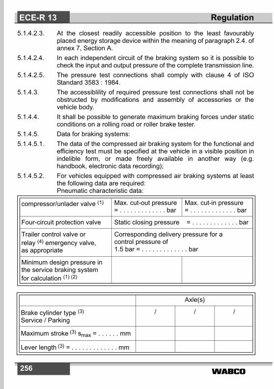
5.1.4.5. Data for braking systems:5.1.4.5.1. The data of the compressed air braking system for the functional and
efficiency test must be specified at the vehicle in a visible position inindelible form, or made freely available in another way (e.g.handbook, electronic data recording);
5.1.4.5.2. For vehicles equipped with compressed air braking systems at leastthe following data are required:Pneumatic characteristic data:
compressor/unlader valve (1) Max. cut-out pressure= . . . . . . . . . . . . . bar
Max. cut-in pressure= . . . . . . . . . . . . . bar
Four-circuit protection valve Static closing pressure = . . . . . . . . . . . . . bar
Trailer control valve orrelay (4) emergency valve,as appropriate
Corresponding delivery pressure for acontrol pressure of 1.5 bar = . . . . . . . . . . . . . bar
Minimum design pressure inthe service braking systemfor calculation (1) (2)
Axle(s)
Brake cylinder type (3)
Service / Parking/ / /
Maximum stroke (3) smax = . . . . . . mm
Lever length (3) = . . . . . . . . . . . . . mm
ECE-R 13 Regulation
����� 257
Notes: (1) Not applicable for trailers;(2) When different from minimum cut-in pressure;(3) Only applicable for trailers.(4) Not applicable for vehicles with electronic control of braking
systems.
5.1.4.6. Reference braking forces5.1.4.6.1. Reference braking forces shall be defined for vehicles with
compressed air operated brakes using a roller brake tester.5.1.4.6.2. Reference braking forces are to be determined for a brake actuator
pressure range from 1 bar to the pressure generated under Type-0conditions for each axle. The applicant for type approval shallnominate reference-braking forces for a brake activator pressurerange from 1 bar. These data shall be made available, by the vehiclemanufacturer, according to paragraph 5.1.4.5.1. above.
5.1.4.6.3. The reference braking forces shall be declared such that the vehicleis capable of generating a braking rate equivalent to that defined inannex 4 of this Regulation for the relevant vehicle (50 per cent in thecase of vehicles of category M2, M3, N2, N3, O3 and O4 except semi-trailers, 45 per cent in the case of semi-trailers), whenever themeasured roller braking force, for each axle irrespective of load, isnot less than the reference braking force for a given brake actuatorpressure within the declared operating pressure range 3).
5.1.4.7. It shall be possible to verify, in a simple way, the correct operationalstatus of those complex electronic systems which have control overbraking. If special information is needed, this shall be made freelyavailable.
5.1.4.7.1. At the time of type approval, the means implemented to protectagainst simple unauthorized modification of the operation to theverification means chosen by the manufacturer (e.g. warning signal)shall be confidentially outlined. Alternatively, this protection requirement is fulfilled when a secondarymeans of checking the correct operational status is available.
5.1.5. The requirements of annex 18 shall be applied to the safety aspectsof all complex electronic vehicle control systems which provide orform part of the control transmission of the braking function included
ECE-R 13Regulation
3) For the purpose of periodic technical inspection, the minimum limit brakingrate values defined for the whole vehicle may need adjustment to reflectnational or international in-service requirements.

�����258
those which utilise the braking system(s) for automaticallycommanded braking or selective braking.However, systems or functions, which use the braking system as themeans of achieving a higher level objective, are subject to annex 18only insofar as they have a direct effect on the braking system. Ifsuch systems are provided, they must not be deactivated during typeapproval testing of the braking system.
5.2. Characteristics of braking systems5.2.1. Vehicles of categories M and N5.2.1.1. The set of braking systems with which a vehicle is equipped must
satisfy the requirements laid down for service, secondary and parkingbraking system.
5.2.1.2. The systems providing service, secondary and parking braking mayhave common components so long as they fulfil the followingconditions:
5.2.1.2.1. there must be at least two controls, independent of each other andreadily accessible to the driver from his normal driving position. Forall categories of vehicles, except M2 and M3, every brake control(excluding a Endurance braking system control) shall be designedsuch that it returns to the fully off position when released. Thisrequirement shall not apply to a parking brake control (or that part ofa combined control) when it is mechanically locked in an appliedposition;
5.2.1.2.2. the control of the service braking system must be independent of thecontrol of the parking braking system;
5.2.1.2.3. if the service braking system and the secondary braking system havethe same control, the effectiveness of the linkage between thatcontrol and the different components of the transmission systemsmust not be liable to diminish after a certain period of use;
5.2.1.2.4. if the service braking system and the secondary braking system havethe same control, the parking braking system must be so designedthat it can be actuated when the vehicle is in motion. Thisrequirement shall not apply if the vehicle's service braking systemcan be actuated, even partially, by means of an auxiliary control;
5.2.1.2.5. without prejudice to the requirements of paragraph 5.1.2.3. of thisRegulation, the service braking system and the parking brakingsystem may use common components in their transmission(s),provided that in the event of a failure in any part of thetransmission(s) the requirements for secondary braking are stillensured;
ECE-R 13 Regulation

����� 259
5.2.1.2.6. in the event of breakage of any component other than the brakes (asdefined in paragraph 2.6. of this Regulation) or the componentsreferred to in paragraph 5.2.1.2.8. below, or of any other failure of theservice braking system (malfunction, partial or total exhaustion of anenergy reserve), the secondary braking system or that part of theservice braking system which is not affected by the failure, must beable to bring the vehicle to a halt in the conditions prescribed forsecondary braking;
5.2.1.2.7. in particular, where the secondary braking system and the servicebraking system have a common control and a common transmission:
5.2.1.2.7.1. if service braking is ensured by the action of the driver's muscularenergy assisted by one or more energy reserves, secondary brakingmust, in the event of failure of that assistance, be capable of beingensured by the driver's muscular energy assisted by the energyreserves, if any, which are unaffected by the failure, the force appliedto the control not exceeding the prescribed maxima;
5.2.1.2.7.2. if the service braking force and transmission depend exclusively onthe use, controlled by the driver, of an energy reserve, there must beat least two completely independent energy reserves, each providedwith its own transmission likewise independent; each of them may acton the brakes of only two or more wheels so selected as to becapable of ensuring by themselves the prescribed degree ofsecondary braking without endangering the stability of the vehicleduring braking; in addition, each of the aforesaid energy reservesmust be equipped with a warning device as defined in paragraph5.2.1.13. below. In each service braking circuit in at least one of theair reservoirs a devive for draining and exhausting is required in anadequate and easily accessible position.
5.2.1.2.7.3. If the service braking force and transmission depend exclusively onthe use of an energy reserve, one energy reserve for thetransmission is deemed to be sufficient, provided that the prescribedsecondary braking is ensured by the action of the driver's muscularenergy acting on the service brake control and the requirements ofparagraph 5.2.1.6. are met.
5.2.1.2.8. Certain parts, such as the pedal and its bearing, the master cylinderand its piston or pistons (hydraulic systems), the control valve(hydraulic and/or pneumatic systems), the linkage between the pedaland the master cylinder or the control valve, the brake cylinders andtheir pistons (hydraulic and/or pneumatic systems), and the lever-and-cam assemblies of brakes, shall not be regarded as liable tobreakage if they are amply dimensioned, are readily accessible formaintenance, and exhibit safety features at least equal to those
ECE-R 13Regulation

�����260
prescribed for other essential components (such as the steeringlinkage) of the vehicle. Any such part as aforesaid whose failurewould make it impossible to brake the vehicle with a degree ofeffectiveness at least equal to that prescribed for secondary brakingmust be made of metal or of a material with equivalent characteristicsand must not undergo notable distortion in normal operation of thebraking systems.
5.2.1.3. Where there are separate controls for the service braking system andthe secondary braking system, simultaneous actuation of the twocontrols must not render both the service braking system and thesecondary braking system inoperative, either when both brakingsystems are in good working order or when one of them is faulty.
5.2.1.4. The service braking system must, whether or not it is combined withthe secondary braking system, be such that in the event of failure in apart of its transmission a sufficient number of wheels are still brakedby actuation of the service brake control; these wheels must be soselected that the residual performance of the service braking systemsatisfies the requirements laid down in paragraph 2.4. of annex 4 tothis Regulation.
5.2.1.4.1. However, the foregoing provisions shall not apply to tractor vehiclesfor semi-trailers when the transmission of the semi-trailer's servicebraking system is independent of that of the tractor vehicle's servicebraking system.
5.2.1.4.2. The failure of a part of a hydraulic transmission system shall besignalled to the driver by a device comprising a red warning signal,as specified in paragraph 5.2.1.29.1.1. Alternatively, the lighting up ofthis device when the fluid in the reservoir is below a certain levelspecified by the manufacturer shall be permitted.
5.2.1.5. Where use is made of energy other than the muscular energy of thedriver, there need not be more than one source of such energy(hydraulic pump, air compressor, etc.), but the means by which thedevice constituting that source is driven must be as safe aspracticable.
5.2.1.5.1. In the event of failure in any part of the transmission of a brakingsystem, the feed to the part not affected by the failure must continueto be ensured if required for the purpose of halting the vehicle withthe degree of effectiveness prescribed for residual and/or secondarybraking. This condition must be met by means of devices which canbe easily actuated when the vehicle is stationary, or by automaticmeans.
ECE-R 13 Regulation

����� 261
5.2.1.5.2. Furthermore, storage devices located down-circuit of this devicemust be such that in the case of a failure in the energy supply afterfour full-stroke actuations of the service brake control, under theconditions prescribed in paragraph 1.2. of annex 7 to this Regulation,it is still possible to halt the vehicle at the fifth application, with thedegree of effectiveness prescribed for secondary braking.
5.2.1.5.3. However, for hydraulic braking systems with stored energy, theseprovisions can be considered to be met provided that therequirements of paragraph 1.2.2. of Part C of annex 7 to thisRegulation, are satisfied.
5.2.1.6. The requirements of paragraphs 5.2.1.2., 5.2.1.4. and 5.2.1.5. of thisRegulation must be met without the use of any automatic device of akind such that its ineffectiveness might pass unnoticed through thefact that parts normally in a position of rest come into action only inthe event of failure in the braking system.
5.2.1.7. The service braking system shall act on all wheels of the vehicle andshall distribute its action appropriately among the axles.
5.2.1.7.1. In the case of vehicles with more than two axles, in order to avoidwheel-locking or glazing of the brake linings, the brake force oncertain axles may be reduced to zero automatically when carrying amuch reduced load, provided that the vehicle meets all theperformance requirements prescribed in annex 4 to this Regulation.
5.2.1.7.2. In the case of M1 and N1 category vehicles with electric regenerativebraking systems of category B, the braking input from other sourcesof braking, may be suitably phased to allow the electric regenerativebraking system alone to be applied, provided that both the followingconditions are met:
5.2.1.7.2.1. Intrinsic variations in the torque output of the electrical regenerativebraking system (e.g. as a result of changes in the electric state ofcharge in the traction batteries) are automatically compensated byappropriate variation in the phasing relationship as long as therequirements *) of one of the following annexes to this Regulation aresatisfied:Annex 4, paragraph 1.3.2. orAnnex 13 paragraph 5.3. (including the case with the electric motorengaged).
5.2.1.7.2.2. Wherever necessary, to ensure that braking rate *) remains related to
ECE-R 13Regulation
*) The Authority, which is to grant approval, shall have the right to check theservice braking system by additional vehicle test procedures.

�����262
the driver's braking demand, having regard to the available tyre/roadadhesion, braking shall automatically be caused to act on all wheelsof the vehicle.
5.2.1.8. The action of the service braking system shall be distributed betweenthe wheels of one and the same axle symmetrically in relation to thelongitudinal median plane of the vehicle. Compensation andfunctions, such as anti-lock, which may cause deviations from thissymmetrical distribution, shall be declared.
5.2.1.8.1. Compensation by the electric control transmission for deterioration ordefect within the braking system shall be indicated to the driver bymeans of the yellow warning signal specified in paragraph5.2.1.29.1.2. This requirement shall apply for all conditions of loadingwhen compensation exceeds the following limits:
5.2.1.8.1.1. a difference in transverse braking pressures on any axle:(a) of 25 per cent of the higher value for vehicle decelerations
� 2m/sec2, (b) a value corresponding to 25 per cent at 2m/sec2 for
decelerations below this rate.5.2.1.8.1.2. an individual compensating value on any axle:
(a) > 50 per cent of the nominal value for vehicle decelerations � 2 m/sec2,
(b) a value corresponding to 50 per cent of the nominal value at 2m/sec2 for decelerations below this rate.
5.2.1.8.2. Compensation as defined above, is permitted only when the initialbrake application is made at vehicle speeds greater than 10 km/h.
5.2.1.9. Malfunctions of the electric control transmission shall not apply thebrakes contrary to the driver's intentions.
5.2.1.10. The service, secondary and parking braking systems must act onbraking surfaces connected to the wheels through components ofadequate strength.Where braking torque for a particular axle or axles is provided byboth a friction braking system and an electrical regenerative brakingsystem of category B, disconnection of the latter source is permitted,providing that the friction braking source remains permanentlyconnected and able to provide the compensation referred to inparagraph 5.2.1.7.2.1.However in the case of short disconnection transients, incompletecompensation is accepted, but within 1 s, this compensation shallhave attained at least 75 per cent of its final value.
ECE-R 13 Regulation
����� 263
Nevertheless, in all cases the permanently connected friction brakingsource shall ensure that both the service and secondary brakingsystems continue to operate with the prescribed degree ofeffectiveness.Disconnection of the braking surfaces of the parking braking systemshall be permitted only on condition that the disconnection iscontrolled exclusively by the driver from his driving seat, by a systemincapable of being brought into action by a leak.
5.2.1.11. Wear of the brakes must be capable of being easily taken up bymeans of a system of manual or automatic adjustment. In addition,the control and the components of the transmission and of the brakesmust possess a reserve of travel and, if necessary, suitable means ofcompensation such that, when the brakes become heated, or thebrake linings have reached a certain degree of wear, effective brakingis ensured without immediate adjustment being necessary.
5.2.1.11.1. Wear adjustment shall be automatic for the service brakes. However,the fitting of automatic brake adjustment devices is optional for offroad vehicles of categories N2 and N3 and for the rear brakes ofvehicles of categories M1 and N1. Brakes equipped with automaticbrake adjustment devices shall, after heating followed by cooling, becapable of free running as defined in paragraph 1.5.4. of annex 4following the Type-I test also defined in that annex.
5.2.1.11.2. Checking the wear of the service brake friction components5.2.1.11.2.1. It shall be possible to easily check this wear on service brake linings
from the outside or underside of the vehicle utilizing only the tools orequipment normally supplied with the vehicle, for instance by theprovision of appropriate inspection holes or by some other means.Alternatively, acoustic or optical devices warning the driver at hisdriving position when lining replacement is necessary are acceptable.The yellow warning signal specified in paragraph 5.2.1.29.1.2. belowmay be used as the optical warning signal.
5.2.1.11.2.2. Assessment of the wear condition of the friction surfaces of brakediscs or drums may only be performed by direct measurement of theactual components, which may necessitate some level ofdisassembly. Therefore, at the time of type approval, the vehiclemanufacturer shall define the following: (a) The method by which wear of the friction surfaces of drums and
discs may be assessed, including the level of disassemblyrequired and tools and process required to achieve this.
(b) Information defining the maximum acceptable wear limit at thepoint at which replacement becomes necessary.
ECE-R 13Regulation

�����264
This information shall be made freely available e.g. vehicle handbookor electronic data record.
5.2.1.12. In hydraulic transmission braking systems, the filling ports of the fluidreservoirs must be readily accessible; in addition, the receptaclescontaining the reserve fluid must be so designed and constructedthat the level of the reserve fluid can be easily checked without thereceptacles having to be opened. If this latter condition is not fulfilled,the red warning signal specified in paragraph 5.2.1.29.1.1. shall drawthe driver's attention to any fall in the level of reserve fluid liable tocause a failure of the braking system. The type of fluid to be used inthe hydraulic transmission braking systems shall be identified by thesymbol in accordance with figure 1 or 2 of ISO Standard 9128: 1987.The symbol must be affixed in a visible position in indelible formwithin 100 mm of the filling ports of the fluid reservoirs; additionalinformation may be provided by the manufacturer.
5.2.1.13. Warning device5.2.1.13.1. Any vehicle fitted with a service brake actuated from an energy
reservoir must, where the prescribed secondary braking performancecannot be obtained by means of this braking system without the useof the stored energy, be provided with a warning device, in addition toa pressure gauge, where fitted, giving an optical or acoustic signalwhen the stored energy, in any part of the system, falls to a value atwhich without re-charging of the reservoir and irrespective of the loadconditions of the vehicle, it is possible to apply the service brakecontrol a fifth time after four full-stroke actuations and obtain theprescribed secondary braking performance (without faults in theservice brake transmission device and with the brakes adjusted asclosely as possible). This warning device must be directly andpermanently connected to the circuit. When the engine is runningunder normal operating conditions and there are no faults in thebraking system, as is the case in approval tests for this type, thewarning device must give no signal except during the time requiredfor charging the energy reservoir(s) after start-up of the engine. Thered warning signal specified in paragraph 5.2.1.29.1.1. shall be usedas the optical warning signal.
5.2.1.13.1.1. However, in the case of vehicles which are only considered to complywith the requirements of paragraph 5.2.1.5.1. of this Regulation byvirtue of meeting the requirements of paragraph 1.2.2. of Part C ofannex 7 to this Regulation, the warning device shall consist of anacoustic signal in addition to an optical signal. These devices neednot operate simultaneously, provided that each of them meet theabove requirements and the acoustic signal is not actuated before
ECE-R 13 Regulation

����� 265
the optical signal. The red warning signal specified in paragraph5.2.1.29.1.1. shall be used as the optical warning signal.
5.2.1.13.1.2. This acoustic device may be rendered inoperative while the handbrake is applied and/or, at the choice of the manufacturer, in the caseof automatic transmission the selector is in the ”Park“ position.
5.2.1.14. Without prejudice to the requirements of paragraph 5.1.2.3., wherean auxiliary source of energy is essential to the functioning of abraking device, the reserve of energy must be such as to ensure that,if the engine stops or in the event of a failure of the means by whichthe energy source is driven, the braking performance remainsadequate to bring the vehicle to a halt in the prescribed conditions. Inaddition, if the muscular effort applied by the driver to the parkingbraking system is reinforced by a servo device, the actuation ofparking braking must be ensured in the event of a failure of the servodevice, if necessary by using a reserve of energy independent of thatnormally supplying the servo device. This reserve of energy may bethat intended for the service braking system.
5.2.1.15. In the case of a power-driven vehicle to which the coupling of a trailerequipped with a brake controlled by the driver of the towing vehicle isauthorized, the service braking system of the towing vehicle must beequipped with a device so designed that in the event of failure of thetrailer's braking system, or in the event of an interruption in the airsupply pipe (or of such other type of connection as may be adopted)between the towing vehicle and its trailer, it shall still be possible tobrake the towing vehicle with the effectiveness prescribed forsecondary braking; it is accordingly prescribed, in particular, that thisdevice shall be situated on the towing vehicle.
5.2.1.16. The pneumatic/hydraulic auxiliary equipment must be supplied withenergy in such a way that during its operation the prescribeddeceleration values can be reached and that even in the event ofdamage to the source of energy the operation of the auxiliaryequipment cannot cause the reserves of energy feeding the brakingsystems to fall below the level indicated in paragraph 5.2.1.13.above.
5.2.1.17. If the trailer is of category O3 or O4, the service braking system mustbe of the continuous or semi-continuous type.
5.2.1.18. In the case of a vehicle authorized to tow a trailer of category O3 orO4, its braking systems must satisfy the following conditions:
5.2.1.18.1. when the towing vehicle's secondary braking system comes intoaction, there must also be a graduated braking action in the trailer;
ECE-R 13Regulation

�����266
5.2.1.18.2. in the event of failure of the towing vehicle's service braking system,where that system consists of at least two independent parts, the partor parts not affected by the failure should be capable of partially orfully actuating the brakes of the trailer. It must be possible tograduate this braking action. If this operation is achieved by a valvewhich is normally at rest, then such a valve may only be incorporatedif its correct functioning can easily be checked by the driver, eitherfrom within the cab or from outside the vehicle, without the use oftools;
5.2.1.18.3. In the event of a failure (e.g. breakage or leak) in one of thepneumatic connecting lines, interruption or defect in the electriccontrol line, it shall nevertheless be possible for the driver fully orpartially to actuate the brakes of the trailer by means either of theservice braking control or of the secondary braking control or of theparking braking control, unless the failure automatically causes thetrailer to be braked with the performance prescribed in paragraph3.3. of annex 4 to this Regulation.
5.2.1.18.4. The automatic braking in paragraph 5.2.1.18.3. above shall beconsidered to be met when the following conditions are fulfilled:
5.2.1.18.4.1. when the designated brake control of the controls mentioned inparagraph 5.2.1.18.3. above is fully actuated, the pressure in thesupply line must fall to 1.5 bar within the following two seconds; inaddition, when the brake control is released, the supply line shall bere-pressurized.
5.2.1.18.4.2. when the supply line is evacuated at the rate of at least 1 bar persecond the automatic braking of the trailer must start to operatebefore the pressure in the supply line falls to 2 bar.
5.2.1.18.5. In the event of a failure in one of the control lines connecting twovehicles equipped according to paragraph 5.1.3.1.2., the control linenot affected by the failure shall automatically ensure the brakingperformance prescribed for the trailer in paragraph 3.1. of annex 4.
5.2.1.19. In the case of a power-driven vehicle equipped to draw a trailer withelectrical braking system, according to paragraph 1.1. of annex 14 tothis Regulation, the following requirements shall be met:
5.2.1.19.1. the power supply (generator and battery) of the power-driven vehicleshall have a sufficient capacity to provide the current for an electricbraking system. With the engine running at the idling speedrecommended by the manufacturer and all electrical devicessupplied by the manufacturer as standard equipment of the vehicleswitched on, the voltage in the electrical lines shall at maximumcurrent consumption of the electrical braking system (15 A) not fall
ECE-R 13 Regulation
����� 267
below the value of 9.6 V measured at the connection. The electricallines shall not be capable of short circuiting even when overloaded.
5.2.1.19.2. in the event of a failure in the towing vehicle's service braking system,where that system consists of at least two independent units, the unitor units not affected by the failure shall be capable of partially or fullyactuating the brakes of the trailer.
5.2.1.19.3. the use of the stop lamp switch and circuit for actuating the electricalbraking system is permissible only if the actuating line is connected inparallel with the stop lamp and the existing stop lamp switch andcircuit are capable of taking the extra-load.
5.2.1.20. In the case of a pneumatic service braking system comprising two ormore independent sections, any leakage between those sections ator downstream of the control shall be continuously vented toatmosphere.
5.2.1.21. In the case of a power driven vehicle authorized to tow a trailer ofcategory O3 or O4, the service braking system of the trailer may onlybe operated in conjunction with the service, secondary or parkingbraking system of the towing vehicle. However, application of thetrailer brakes alone is permitted where the operation of the trailerbrakes is initiated automatically by the towing vehicle for the solepurpose of vehicle stabilization. **)
5.2.1.22. Power-driven vehicles of categories M2, M3, N2 and N3 with not morethan four axles shall be equipped with anti-lock braking systems ofcategory 1 in accordance with annex 13 to this Regulation.
5.2.1.23. Power-driven vehicles of category M1 equipped with temporary-usespare wheels/tyres shall satisfy the technical requirements of annex 3to Regulation no. 64.
5.2.1.24. Power-driven vehicles authorized to tow a trailer equipped with ananti-lock system shall also be equipped with a special electricalconnector, conforming to ISO 7638:1997 *), for the electric controltransmission and/or the anti-lock braking systems of trailers.
5.2.1.25. Additional requirements for vehicles of categories M1, M2, N1 andcategory N2 < 5 tonnes equipped with an electric regenerativebraking system.
ECE-R 13Regulation
*) The ISO 7638:1997 connector may be used for 5 pin or 7 pin applications,as appropriate.
**) adapted by GRRF/54

�����268
5.2.1.25.1. Vehicles fitted with an electric regenerative braking system ofcategory A.
5.2.1.25.1.1. The electric regenerative braking shall only be actuated by theaccelerator control and/or the gear selector neutral position forvehicles of category M1 or N1.
5.2.1.25.1.2. In addition, for vehicles of categories M2 and N2 (< 5 tons), theelectric regenerative braking control can be a separate switch orlever.
5.2.1.25.2. Vehicles fitted with an electric regenerative braking system ofcategory B.
5.2.1.25.2.1. It shall not be possible to disconnect, partially or totally, one part ofthe service braking system other than by automatic means. Thisshould not be construed as a departure from the requirements ofparagraph 5.2.1.10.
5.2.1.25.2.2. The service braking system shall have only one control device.5.2.1.25.2.3. For vehicles fitted with an electric regenerative braking system of
both categories, all the relevant prescriptions shall apply exceptparagraph 5.2.1.25.1.1.In this case, the electric regenerative braking may be actuated by theaccelerator control and/or the gear selector neutral position forvehicles of category M1 or N1.
Additionally, the action on the service braking control must notreduce the above braking effect generated by the release ofaccelerator control.
5.2.1.25.2.4. The service braking system shall not be adversely affected by thedisengagement of the motor(s) or by the gear ratio used.
5.2.1.25.2.5. If the operation of the electric component of braking is ensured by arelation established between the information coming from the controlof the service brake and the braking force at the respective wheels, afailure of this relation leading to the modification of the brakingdistribution among the axles (Annex 10 or 13, whichever isapplicable) must be signalled to the driver by an optical warningsignal at the latest at the moment when the control is actuated andthis signal shall remain lit as long as this defect exists and that thevehicle control switch (key) is in the ”ON“ position.
5.2.1.25.3. The operation of the electric regenerative braking must not beadversely affected by magnetic or electric fields.
5.2.1.25.4. For vehicles equipped with an antilock device, the antilock deviceshall control the electric regenerative braking system.
ECE-R 13 Regulation
����� 269
5.2.1.26. Special additional requirements for the electric transmission of theparking braking system.
5.2.1.26.1. In the case of a failure within the electric transmission, anyunintended actuation of the parking braking system shall beprevented.
5.2.1.26.2. In the case of a break in the wiring within the electric controltransmission external to the electronic control unit(s) and excludingthe energy supply, or a failure in the control, it shall remain possibleto apply the parking braking system from the driver's seat andthereby be capable of holding the laden vehicle stationary on an 8per cent up or down gradient. Alternatively, in this case, an automaticactuation of the parking brake is allowed when the vehicle isstationary, provided that the above performance is achieved and,once applied, the parking brake remains engaged independently ofthe status of the ignition (start) switch. In this alternative, the parkingbrake shall be automatically released as soon as the driver starts toset the vehicle in motion again. In the case of vehicles of categoriesM1 and N1, the engine/manual transmission or the automatictransmission (park position) may be used to achieve or assist inachieving the above performance. It shall also be possible to releasethe parking braking system, if necessary by the use of tools and/or anauxiliary device carried/fitted on the vehicle.
5.2.1.26.2.1. A break in the wiring within the electric transmission, or a failure inthe control of the parking braking system shall be signalled to thedriver by the yellow warning signal specified in paragraph5.2.1.29.1.2. When caused by a break in the wiring within the electriccontrol transmission of the parking braking system, this yellowwarning signal shall be signalled as soon as the break occurs. Inaddition, such a failure in the control or break in the wiring external tothe electronic control unit(s) and excluding the energy supply shall besignalled to the driver by flashing the red warning signal specified inparagraph 5.2.1.29.1.1. as long as the ignition (start) switch is in the”ON“ (run) position including a period of not less than 10 secondsthereafter and the control is in the ”ON“ (activated) position. Whereactuation of the parking brake is normally indicated by a separate redwarning signal, satisfying all the requirements of 5.2.1.29.3., thissignal shall be used to satisfy the above requirement for a red signal.
5.2.1.26.3. Auxiliary equipment may be supplied with energy from the electrictransmission of the parking braking system provided that the supplyof energy is sufficient to allow the actuation of the parking brakingsystem in addition to the vehicle electrical load under non-faultconditions. In addition, where the energy reserve is also used by the
ECE-R 13Regulation

�����270
service braking system, the requirements of paragraph 5.2.1.27.7.shall apply.
5.2.1.26.4. After the ignition/start switch which controls the electrical energy forthe braking equipment has been switched off and/or the keyremoved, it shall remain possible to apply the parking brakingsystem, whereas releasing shall be prevented.
5.2.1.27. Special additional requirements for service braking systems withelectric control transmission.
5.2.1.27.1. With the parking brake released, the service braking system shall beable to generate a static total braking force at least equivalent to thatrequired by the prescribed Type-0 test, even when the ignition/startswitch has been switched off and/or the key has been removed. Inthe case of power-driven vehicles authorized to tow trailers ofcategory O3 or O4, such vehicles shall provide a full control signal forthe service braking system of the trailer. It should be understood thatsufficient energy is available in the energy transmission of the servicebraking system.
5.2.1.27.2. In the case of a single temporary failure (< 40 ms) within the electriccontrol transmission, excluding its energy supply, (e.g. non-transmitted signal or data error) there shall be no distinguishableeffect on the service braking performance.
5.2.1.27.3. A failure within the electric control transmission 4), not including itsenergy reserve, that affects the function and performance of systemsaddressed in this Regulation shall be indicated to the driver by thered or yellow warning signal specified in paragraphs 5.2.1.29.1.1.and 5.2.1.29.1.2., respectively, as appropriate. When the prescribedservice braking performance can no longer be achieved (red warningsignal), failures resulting from a loss of electrical continuity (eg.breakage, disconnection) shall be signalled to the driver as soon asthey occur, and the prescribed residual braking performance shall befulfilled by operating the service braking control in accordance withparagraph 2.4. of annex 4 to this Regulation. These requirementsshall not be construed as a departure from the requirementsconcerning secondary braking.
5.2.1.27.4. A power-driven vehicle, electrically connected to a trailer via anelectric control line, shall provide a clear warning to the driver
ECE-R 13 Regulation
4) Until uniform test procedures have been agreed, the manufacturer shall pro-vide the Technical Service with an analysis of potential failures within thecontrol transmission and their effects. This information shall be subject todiscussion and agreement between the Technical Service and the vehiclemanufacturer.

����� 271
whenever the trailer provides the failure information that the storedenergy in any part of the service braking system on the trailer fallsbelow the warning level, as specified in paragraph 5.2.2.16. below. Asimilar warning shall also be provided when a continuous failure(> 40 ms) within the electric control transmission of the trailer,excluding its energy reserve, precludes achievement of theprescribed service braking performance of the trailer, as specified inparagraph 5.2.2.15.2.1. below. The red warning signal specified inparagraph 5.2.1.29.2.1. shall be used for this purpose.
5.2.1.27.5. In the event of a failure of the energy source of the electric controltransmission, starting from the nominal value of the energy level, thefull control range of the service braking system shall be guaranteedafter twenty consecutive full stroke actuations of the service brakingcontrol. During the test, the braking control shall be fully applied for20 seconds and released for 5 seconds on each actuation. It shouldbe understood that during the above test sufficient energy is availablein the energy transmission to ensure full actuation of the servicebraking system. This requirement shall not be construed as adeparture from the requirements of annex 7.
5.2.1.27.6. When the battery voltage falls below a value nominated by themanufacturer at which the prescribed service braking performancecan no longer be guaranteed and/or which precludes at least twoindependent service braking circuits from each achieving theprescribed secondary or residual braking performance, the redwarning signal specified in paragraph 5.2.1.29.1.1. shall be activated.After the warning signal has been activated, it shall be possible toapply the service braking control and obtain at least the residualperformance prescribed in paragraph 2.4. of annex 4 to thisRegulation. It should be understood that sufficient energy is availablein the energy transmission of the service braking system. Thisrequirement shall not be construed as a departure from therequirement concerning secondary braking.
5.2.1.27.7. If auxiliary equipment is supplied with energy from the same reserve asthe electric control transmission, it shall be ensured that, with theengine running at a speed not greater than 80 per cent of themaximum power speed, the supply of energy is sufficient to fulfil theprescribed deceleration values by either provision of an energy supplywhich is able to prevent discharge of this reserve when all auxiliaryequipment is functioning or by automatically switching off pre-selectedparts of the auxiliary equipment at a voltage above the critical levelreferred to in paragraph 5.2.1.27.6 of this Regulation such that furtherdischarge of this reserve is prevented. Compliance may bedemonstrated by calculation or by a practical test. For vehicles
ECE-R 13Regulation

�����272
authorized to tow a trailer of category O3 or O4 the energyconsumption of the trailer shall be taken into account by a load of400 W. This paragraph does not apply to vehicles where theprescribed deceleration values can be reached without the use ofelectrical energy.
5.2.1.27.8. If the auxiliary equipment is supplied with energy from the electriccontrol transmission, the following requirements shall be fulfilled.
5.2.1.27.8.1. In the event of a failure in the energy source, whilst the vehicle is inmotion, the energy in the reservoir shall be sufficient to actuate thebrakes when the control is applied.
5.2.1.27.8.2. In the event of a failure in the energy source, whilst the vehicle isstationary and the parking braking system applied, the energy in thereservoir shall be sufficient to actuate the lights even when thebrakes are applied.
5.2.1.27.9. In the case of a failure in the electric control transmission of theservice braking system of a towing vehicle equipped with an electriccontrol line according to paragraph 5.1.3.1.2. or 5.1.3.1.3., the fullactuation of the brakes of the trailer shall remain ensured.
5.2.1.27.10. In the case of a failure in the electric control transmission of a trailer,electrically connected via an electric control line only, according toparagraph 5.1.3.1.3., braking of the trailer shall be ensured accordingto paragraph 5.2.1.18.4.1. This shall be the case whenever the trailerprovides the ”supply line braking request“ signal via the datacommunication part of the electric control line or in the event of thecontinuous absence of this data communication. This paragraphshall not apply to power-driven vehicles which cannot be operatedwith trailers connected via an electric control line only, as describedin paragraph 5.1.3.5.
5.2.1.28. Special requirements for coupling force control.5.2.1.28.1. Coupling force control shall only be permitted in the towing vehicle.5.2.1.28.2. The action of the coupling force control shall be to reduce the
difference between the dynamic braking rates of towing and towedvehicles. The operation of the coupling force control shall be checkedat the time of type approval. The method by which this check is carriedout shall be agreed between the vehicle manufacturer and thetechnical service with the method of assessment and results beingappended to the type approval report.
5.2.1.28.2.1. The coupling force control may control the braking rate TM/PM and/orthe brake demand value(s) for the trailer. In the case of a towing vehicle
ECE-R 13 Regulation
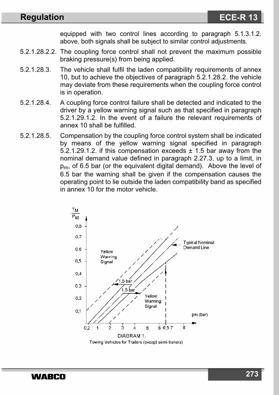
����� 273
equipped with two control lines according to paragraph 5.1.3.1.2.above, both signals shall be subject to similar control adjustments.
5.2.1.28.2.2. The coupling force control shall not prevent the maximum possiblebraking pressure(s) from being applied.
5.2.1.28.3. The vehicle shall fulfil the laden compatibility requirements of annex10, but to achieve the objectives of paragraph 5.2.1.28.2. the vehiclemay deviate from these requirements when the coupling force controlis in operation.
5.2.1.28.4. A coupling force control failure shall be detected and indicated to thedriver by a yellow warning signal such as that specified in paragraph5.2.1.29.1.2. In the event of a failure the relevant requirements ofannex 10 shall be fulfilled.
5.2.1.28.5. Compensation by the coupling force control system shall be indicatedby means of the yellow warning signal specified in paragraph5.2.1.29.1.2. if this compensation exceeds ± 1.5 bar away from thenominal demand value defined in paragraph 2.27.3. up to a limit, inpm, of 6.5 bar (or the equivalent digital demand). Above the level of6.5 bar the warning shall be given if the compensation causes theoperating point to lie outside the laden compatibility band as specifiedin annex 10 for the motor vehicle.
ECE-R 13Regulation

�����274
5.2.1.28.6. A coupling force control system shall control only the coupling forcesgenerated by the service braking system of the motor vehicle and thetrailer. Coupling forces resulting from the performance of endurancebraking systems shall not be compensated by the service brakingsystems of either the motor vehicle or trailer. It is considered thatendurance braking systems are not part of the service brakingsystems.
5.2.1.29. The general requirements for optical warning signals whose functionis to indicate to the driver certain specified failures (or defects) withinthe braking equipment of the power-driven vehicle or, whereappropriate, its trailer, are set out in the following sub-paragraphs.Other than as described in paragraph 5.2.1.29.6. below, thesesignals shall be used exclusively for the purposes prescribed by thisRegulation.
5.2.1.29.1. Power-driven vehicles shall be capable of providing optical brakefailure and defect warning signals, as follows:
5.2.1.29.1.1. a red warning signal, indicating failures defined elsewhere in thisRegulation within the vehicle braking equipment which precludeachievement of the prescribed service braking performance and/orwhich preclude the functioning of at least one of two independentservice braking circuits;
ECE-R 13 Regulation

����� 275
5.2.1.29.1.2. where applicable, a yellow warning signal indicating an electricallydetected defect within the vehicle braking equipment, which is notindicated by the red warning signal described in paragraph5.2.1.29.1.1. above.
5.2.1.29.2. With the exception of vehicles of categories M1 and N1, power-drivenvehicles equipped with an electric control line and/or authorised totow a trailer equipped with an electric control transmission and/oranti-lock braking system, shall be capable of providing a separateyellow warning signal to indicate a defect within the anti-lock brakingsystem and/or electric control transmission of the braking equipmentof the trailer. The signal shall be activated from the trailer via pin 5 ofthe electric connector conforming to ISO 7638:1997. *) and in allcases the signal transmitted by the trailer shall be displayed withoutsignificant delay or modification by the towing vehicle. This warningsignal shall not light up when coupled to a trailer without an electriccontrol line and/or electric control transmission and/or anti-lockbraking system or when no trailer is coupled. This function shall beautomatic.
5.2.1.29.2.1. In the case of a power-driven vehicle equipped with an electriccontrol line, when electrically connected to a trailer with an electriccontrol line, the red warning signal specified in paragraph5.2.1.29.1.1. above shall also be used to indicate certain specifiedfailures within the braking equipment of the trailer, whenever thetrailer provides corresponding failure information via the datacommunication part of the electric control line. This indication shall bein addition to the yellow warning signal specified in paragraph5.2.1.29.2. above. Alternatively, instead of utilizing the red warningsignal specified in paragraph 5.2.1.29.1.1. and the accompanyingyellow warning signal above, a separate red warning signal may beprovided in the towing vehicle to indicate such a failure within thebraking equipment of the trailer.
5.2.1.29.3. The warning signals shall be visible, even by daylight; the satisfactorycondition of the signals shall be easily verifiable by the driver from thedriver's seat; the failure of a component of the warning devices shallnot entail any loss of the braking system's performance.
5.2.1.29.4. Except where stated otherwise:5.2.1.29.4.1. a specified failure or defect shall be signalled to the driver by the
above-mentioned warning signal(s) not later than on actuation of therelevant braking control;
ECE-R 13Regulation
*) The ISO 7638:1997 connector may be used for 5 pin or 7 pin applications,as appropriate.

�����276
5.2.1.29.4.2. the warning signal(s) shall remain displayed as long as the failure/defect persists and the ignition (start) switch is in the ”on“ (run)position; and
5.2.1.29.4.3. the warning signal shall be constant (not flashing).5.2.1.29.5. The warning signal(s) mentioned above shall light up when the
electrical equipment of the vehicle (and the braking system) isenergized. With the vehicle stationary, the braking system shall verifythat none of the specified failures or defects are present beforeextinguishing the signals. Specified failures or defects which shouldactivate the warning signals mentioned above, but which are notdetected under static conditions, shall be stored upon detection andbe displayed at start-up and at all times when the ignition (start)switch is in the ”on“ (run) position, as long as the failure or defectpersists.
5.2.1.29.6. Non-specified failures (or defects), or other information concerningthe brakes and/or running gear of the power-driven vehicle, may beindicated by the yellow signal specified in paragraph 5.2.1.29.1.2.above, provided that all the following conditions are fulfilled:
5.2.1.29.6.1. the vehicle is stationary;5.2.1.29.6.2. after the braking equipment is first energised and the signal has
indicated that, following the procedures detailed in paragraph5.2.1.29.5. above, no specified failures (or defects) have beenidentified; and
5.2.1.29.6.3. non-specified faults or other information shall be indicated only by theflashing of the warning signal. However, the warning signal shall beextinguished by the time when the vehicle first exceeds 10 km/h.
[5.2.1.30. *) Generation of a signal to illuminate stop lamps.
5.2.1.30.1. Activation of the service braking system by the driver shall generate asignal that will be used to illuminate the stop lamps.
5.2.1.30.2. Operation of an endurance braking system shall generate the signalmentioned above. However, it is not required to generate this signalwhen the exhaust brake is operated or when the retarding forcegenerated by an endurance braking system is similar to that of anexhaust brake.
5.2.1.30.3. Activation of the service braking system by ”automaticallycommanded braking“ shall generate the signal mentioned above.
RegulationECE-R 13
*) under discussion - Nov. 2003.

����� 277
5.2.1.30.4. Activation of part of the service braking system by ”selective braking“shall not generate the signal mentioned above *).
5.2.1.30.5. In the case of vehicles equipped with an electric control line the signalshall be generated by the motor vehicle when a message ”illuminatestop lamps“ is received via the electric control line from the trailer **).
5.2.1.30.6. ] Electric regenerative braking systems, which produce a retardingforce upon release of the throttle pedal, shall not generate a signalmentioned above.
5.2.2. Vehicles of category O5.2.2.1. Trailers of category O1 need not be equipped with a service braking
system; however, if a trailer of this category is equipped with aservice braking system, it must satisfy the same requirements as atrailer of category O2.
5.2.2.2. Trailers of category O2 must be equipped with a service brakingsystem either of the continuous or semi-continuous or of the inertia(overrun) type. The latter type shall be authorized only for trailersother than semi-trailers. However, electrical braking systemsconforming to the requirements of annex 14 to this Regulation shallbe permitted.
5.2.2.3. Trailers of categories O3 and O4 must be equipped with a servicebraking system of the continuous or semi-continuous type.
5.2.2.4. The service braking system:5.2.2.4.1. shall act on all the wheels of the vehicle;5.2.2.4.2. shall distribute its action appropriately among the axles;5.2.2.4.3. shall contain in at least one of the air reservoir a device for draining
and exhausting in an adequate and easily accessible position.5.2.2.5. The action of the service braking system shall be distributed between
the wheels of one and the same axle symmetrically in relation to thelongitudinal median plane of the vehicle. Compensation andfunctions, such as anti-lock, which may cause deviations from thissymmetrical distribution, shall be declared.
5.2.2.5.1. Compensation by the electric control transmission for deterioration or
Regulation ECE-R 13
*) During a ”selective braking“ event, the function may change to ”automaticallycommanded braking“.
**) This requirement shall not apply until the ISO 11992 has been amended toinclude a message ”illuminate stop lamps“.

�����278
defect within the braking system shall be indicated to the driver bymeans of the separate yellow optical warning signal specified inparagraph 5.2.1.29.2. This requirement shall apply for all conditionsof loading when compensation exceeds the following limits:
5.2.2.5.1.1. a difference in transverse braking pressures on any axle:(a) of 25 per cent of the higher value for vehicle decelerations
� 2m/sec2, (b) a value corresponding to 25 per cent at 2m/sec2 for
decelerations below this rate.5.2.2.5.1.2. an individual compensating value on any axle:
(a) > 50 per cent of the nominal value for vehicle decelerations � 2m/sec2,
(b) a value corresponding to 50 per cent of the nominal value at 2m/sec2 for decelerations below this rate.
5.2.2.5.2. Compensation as defined above, is permitted only when the initialbrake application is made at vehicle speeds greater than 10 km/h.
5.2.2.6. Malfunctions of the electric control transmission shall not apply thebrakes contrary to the driver's intentions;
5.2.2.7. The braking surfaces required to attain the prescribed degree ofeffectiveness must be in constant connection with the wheels, eitherrigidly or through components not liable to failure.
5.2.2.8. Wear of the brakes must be capable of being easily taken up bymeans of a system of manual or automatic adjustment. In addition,the control and the components of the transmission and of the brakesmust possess a reserve of travel and, if necessary, suitable means ofcompensation such that, when the brakes become heated or thebrake linings have reached a certain degree of wear, effectivebraking is ensured without immediate adjustment being necessary.
5.2.2.8.1. Wear adjustment shall be automatic for the service brakes. However,the fitting of automatic adjustment devices is optional for vehicles ofcategories O1 and O2. Brakes equipped with automatic brakeadjustment devices shall, after heating followed by cooling, becapable of free running as defined in paragraph 1.7.3. of annex 4following the Type-I or Type-III test also defined in that annex asappropriate.
5.2.2.8.1.1. In the case of trailers of category O4 the performance requirementsof paragraph 5.2.2.8.1. above shall be deemed to be satisfied byfulfilling the requirements of paragraph 1.7.3. of annex 4.
5.2.2.8.1.2. In the case of trailers of categories O2 and O3 the performance
RegulationECE-R 13

����� 279
requirements of paragraph 5.2.2.8.1. above shall be deemed to besatisfied by fulfilling the requirements of paragraph 1.7.3. 5) of annex 4.
5.2.2.8.2. Checking the wear of the service brake friction components5.2.2.8.2.1. It shall be possible to easily check this wear on service brake linings
from the outside or underside of the vehicle utilizing only the tools orequipment normally supplied with the vehicle, for instance, by theprovision of appropriate inspection holes or by some other means.
5.2.2.8.2.2. Assessment of the wear condition of the friction surfaces of brakediscs or drums may only be performed by direct measurement of theactual components, which may necessitate some level ofdisassembly. Therefore, at the time of type approval, the vehiclemanufacturer shall define the following: (a) The method by which wear of the friction surfaces of drums and
discs may be assessed, including the level of disassemblyrequired and tools and process required to achieve this.
(b) Information defining the maximum acceptable wear limit at thepoint at which replacement becomes necessary.
This information shall be made freely available e.g. vehicle handbookor electronic data record.
5.2.2.9. The braking systems must be such that the trailer is stoppedautomatically if the coupling separates while the trailer is in motion.However, this provision shall not apply to trailers with a maximummass not exceeding 1.5 tons, on the condition that the trailers areequipped with, in addition to the coupling device, a secondarycoupling (chain, wire rope, etc.) capable, in the event of separation ofthe main coupling, of preventing the drawbar from touching theground and providing some residual steering action on the trailer.
5.2.2.10. On every trailer which is required to be equipped with a servicebraking system, parking braking must be assured even when thetrailer is separated from the towing vehicle. The parking brakingdevice must be capable of being actuated by a person standing onthe ground; however, in the case of a trailer used for the carriage ofpassengers, this brake must be capable of being actuated from insidethe trailer.
5.2.2.11. If the trailer is fitted with a device enabling compressed-air actuation
Regulation ECE-R 13
5) Until uniform technical provisions have been agreed that correctly assessthe function of the automatic brake adjustment device, the free runningrequirement shall be deemed to be fulfilled when free running is observedduring all brake tests prescribed for the relevant trailer.
�����280
of the braking system other than the parking braking system to be cutout, the first-mentioned system must be so designed and constructedthat it is positively restored to the position of rest not later than onresumption of the supply of compressed air to the trailer.
5.2.2.12. Trailers of categories O3 and O4 shall satisfy the conditions specifiedin paragraph 5.2.1.18.4.2. An easily accessible pressure testconnection is required downstream of the coupling head of thecontrol line.
5.2.2.12.1. In the case of trailers equipped with an electric control line andelectrically connected to a towing vehicle with an electric control linethe automatic braking action specified in paragraph 5.2.1.18.4.2. maybe suppressed as long as the pressure in the compressed airreservoirs of the trailer is sufficient to ensure the brakingperformance specified in paragraph 3.3 of annex 4 to this Regulation.
5.2.2.13. Trailers of categories O3 and O4 shall be equipped with anti-locksystems in accordance with the requirements of annex 13 to thisRegulation.
5.2.2.14. Where the auxiliary equipment is supplied with energy from theservice braking system, the service braking system shall beprotected to ensure that the sum of the braking forces exerted at theperiphery of the wheels shall be at least 80 percent of the valueprescribed for the relevant trailer as defined in paragraph 3.1.2.1. ofannex 4 to this Regulation. This requirement shall be fulfilled underboth of the following operating conditions:During operation of the auxiliary equipment; andIn the event of breakage or leakage from the auxiliary equipment,unless such breakage or leakage affects the control signal referred toin paragraph 6. to annex 10 to this Regulation, in which case theperformance requirements of that paragraph shall apply.
5.2.2.14.1. The above provisions are deemed to be fulfilled when the pressure inthe service brake storage device(s) is maintained at a pressure of atleast 80 percent of the control line demand pressure or equivalentdigital demand as defined in paragraph 3.1.2.2. of annex 4 to thisRegulation.
5.2.2.15. Special additional requirements for service braking systems withelectric control transmission.
5.2.2.15.1. In the case of a single temporary failure (< 40 ms) within the electriccontrol transmission, excluding its energy supply, (e.g. non-transmitted signal or data error) there shall be no distinguishableeffect on the service braking performance.
RegulationECE-R 13

����� 281
5.2.2.15.2. In the case of a failure within the electric control transmission (e.g.breakage, disconnection), a braking performance of at least 30 percent of the prescribed performance for the service braking system ofthe relevant trailer shall be maintained. For trailers, electricallyconnected via an electric control line only, according to paragraph5.1.3.1.3., and fulfilling 5.2.1.18.4.2. with the performance prescribedin paragraph 3.3. of annex 4 to this Regulation, it is sufficient that theprovisions of paragraph 5.2.1.27.10. are invoked, when a brakingperformance of at least 30 per cent of the prescribed performance forthe service braking system of the trailer can no longer be ensured, byeither providing the ”supply line braking request“ signal via the datacommunication part of the electric control line or by the continuousabsence of this data communication.
5.2.2.15.2.1. A failure within the electric control transmission of the trailer, notincluding its energy reserve, that affects the function andperformance of systems addressed in this Regulation, shall beindicated to the driver by the separate warning signal specified inparagraph 5.2.1.29.2. via pin 5 of the electrical connector conformingto ISO 7638:1997. 6). In addition, trailers equipped with an electriccontrol line, when electrically connected to a towing vehicle with anelectric control line, shall provide the failure information for activationof the red warning signal specified in paragraph 5.2.1.29.2.1. via thedata communication part of the electric control line, when theprescribed service braking performance of the trailer can no longerbe ensured.
5.2.2.16. When the stored energy in any part of the service braking system of atrailer equipped with an electric control line and electrically connectedto a towing vehicle with an electronic control line falls to the valuedetermined in accordance with paragraph 5.2.2.16.1. below, awarning shall be provided to the driver of the towing vehicle. Thewarning shall be provided by activation of the red signal specified inparagraph 5.2.1.29.2.1. and the trailer shall provide the failureinformation via the data communication part of the electric controlline. The separate yellow warning signal specified in paragraph5.2.1.29.2. shall also be activated via pin 5 of the electrical connector
Regulation ECE-R 13
6) Until uniform test procedures have been agreed, the manufacturer shall pro-vide the Technical Service with an analysis of potential failures within thecontrol transmission, and their effects. This information shall be subject todiscussion and agreement between the Technical Service and the vehiclemanufacturer. The ISO 7638:1997 connector may be used for 5 pin or 7 pinapplications, as appropriate.

�����282
conforming to ISO 7638:1997, to indicate to the driver that the low-energy situation is on the trailer.
5.2.2.16.1. The low energy value referred to in paragraph 5.2.2.16. above shallbe that at which, without re-charging of the energy reservoir andirrespective of the load condition of the trailer, it is not possible toapply the service braking control a fifth time after four full-strokeactuations and obtain at least 50 per cent of the prescribedperformance of the service braking system of the relevant trailer.
5.2.2.17. Trailers equipped with an electric control line and O3 and O4 categorytrailers equipped with an anti-lock system, shall be fitted with aspecial electrical connector for the braking system and/or anti-locksystem, conforming to ISO 7638:1997.7) Failure warning signalsrequired from the trailer by this Regulation shall be activated via theabove connector. The requirement to be applied to trailers withrespect to the transmission of failure warning signals shall be those,as appropriate, which are prescribed for motor vehicles inparagraphs 5.2.1.29.4., 5.2.1.29.5. and 5.2.1.29.6.
5.2.2.17.1. Trailers that utilize selective braking as a means to enhance vehiclestability shall in the event of a failure within the electric controltransmission of the stability system indicate the failure by theseparate yellow warning signal specified in paragraph 5.2.1.29.2.above via pin 5 of the ISO 7638:1997 connector.
Note: This requirement shall be kept under review duringsubsequent amendments to Regulation No. 13 pending:(i) an amendment to the ISO 11992 data communication standard
that includes a message to indicate a failure within the electriccontrol transmission of the trailer stability control system; and
(ii) vehicles equipped to that standard are in general use.
5.2.2.17.2. It is not prohibited to provide an additional power supply to thatavailable from the ISO 7638:1997 connector defined above.However, when such a power supply is provided the operation of thebraking system shall not be adversely affected by the connection ofthe additional power supply in normal and failed modes.
RegulationECE-R 13
7) The wiring specifications of ISO 7638:1997 for the trailer not equipped withan electric control transmission may be reduced if the trailer is installed withits own independent fuse. The rating of the fuse shall be such that the cur-rent rating of the conductors is not exceeded.
����� 283
5.2.2.18. Whenever power supplied by the ISO 7638:1997 connector is usedfor the functions defined in paragraph 5.1.3.6. above, the brakingsystem shall have priority and be protected from an overload externalto the braking system. This protection shall be a function of thebraking system.
5.2.2.19. In the case of a failure in one of the control lines connecting twovehicle equipped according to paragraph 5.1.3.1.2. the trailer shalluse the control line not affected by the failure to ensure,automatically, the braking performance prescribed for the trailer inparagraph 3.1. of annex 4.
5.2.2.20. When the supply voltage to the trailer falls below a value nominatedby the manufacturer at which the prescribed service brakingperformance can no longer be guaranteed, the separate yellowwarning signal specified in paragraph 5.2.1.29.2. shall be activatedvia pin 5 of the ISO 7638:1997 *) connector. In addition, trailersequipped with an electrical control line, when electrically connectedto a towing vehicle with an electric control line, shall provide thefailure information for actuation of the red warning signal specified inparagraph 5.2.1.29.2.1. via the data communication part of theelectric control line.
5.2.2.21. In addition to the requirements of paragraphs 5.2.1.18.4.2. and5.2.1.21. above, the brakes of the trailer may also be appliedautomatically when this is initiated by the trailer braking system itselffollowing the evaluation of on-board generated information.
6. TESTSBraking tests which the vehicles submitted for approval are requiredto undergo, and the braking performance required, are described inannex 4 to this Regulation.
7. MODIFICATlONS OF VEHICLE TYPE OR BRAKING SYS-TEM AND EXTENSION OF APPROVAL
7.1. Every modification of the vehicle type or of its braking equipment withregard to the characteristics in annex 2 shall be notified to theadministrative department which approved the vehicle type. Thatdepartment may then either:
Regulation ECE-R 13
*) see 6) on page 281

�����284
7.1.1. consider that the modifications made are unlikely to have anappreciable adverse effect and that in any case the vehicle still meetsthe requirements or
7.1.2. require a further report from the Technical Service responsible forcarrying out the tests.
7.2. Confirmation or refusal of approval, specifying the alterations, shallbe communicated by the procedure specified in paragraph 4.3.above, to the Parties to the Agreement which apply this Regulation.
7.3. The competent authority issuing the extension of approval shallassign a series number to each communication form drawn up forsuch an extension and inform the other Contracting Parties to the1958 Agreement by means of a communication form conforming tothe model in annex 2 to this Regulation.
8. CONFORMITY OF PRODUCTION8.1. A vehicle approved to this Regulation shall be so manufactured as to
conform to the type approved by meeting the requirements set forthin paragraph 5. above.
8.2. In order to verify that the requirements of paragraph 8.1. above, aremet, suitable controls of the production shall be carried out.
8.3. The holder of the approval shall in particular:8.3.1. ensure existence of procedures for the effective control of the quality
of products;8.3.2. have access to the control equipment necessary for checking the
conformity to each approved type;8.3.3. ensure that data of test results are recorded and that annexed
documents shall remain available for a period to be determined inaccordance with the Administrative Service;
8.3.4. analyse the results of each type of test, in order to verify and ensurethe stability of the product characteristics making allowance forvariation of an industrial production;
8.3.5. ensure that for each type of product the tests, or some of them,prescribed in this Regulation are carried out;
8.3.6. ensure that any samples or test pieces giving evidence of non-conformity with the type of test considered shall give rise to anothersampling and another test. All the necessary steps shall be taken tore-establish the conformity of the corresponding production.
RegulationECE-R 13

����� 285
8.4. The competent authority which has granted type approval may at anytime verify the conformity control methods applicable to eachproduction unit.
8.4.1. At every inspection, the test books and production survey recordsshall be presented to the visiting inspector.
8.4.2. The inspector may take samples at random which will be tested in themanufacturer's laboratory. The minimum number of samples may bedetermined according to the results of the manufacturer's ownverification.
8.4.3. When the quality level appears unsatisfactory or when it seemsnecessary to verify the validity of the tests carried out in application ofparagraph 8.4.2. above, the inspector shall select samples to be sentto the Technical Service which has conducted the type approval tests.
8.4.4. The competent authority may carry out any test prescribed in thisRegulation.
8.4.5. The normal frequency of inspections by the competent authority shallbe one every two years. If unsatisfactory results are recorded duringone of these visits, the competent authority shall ensure that allnecessary steps are taken to re-establish the conformity ofproduction as rapidly as possible.
9. PENALTIES FOR NON-CONFORMITY OF PRODUCTION9.1. The approval granted in respect of a vehicle type pursuant to this
Regulation may be withdrawn if the requirements laid down inparagraph 8.1. above are not complied with.
9.2. If a Contracting Party to the Agreement which applies this Regulationwithdraws an approval it has previously granted, it shall forthwith sonotify the other Contracting Parties applying this Regulation bymeans of a copy of a communication form conforming to the model inannex 2 to this Regulation.
10. PRODUCTION DEFlNlTELY DISCONTINUEDIf the holder of the approval completely ceases to manufacture a typeof vehicle approved in accordance with this Regulation, he shall soinform the authority which granted the approval. Upon receiving therelevant communication, that authority shall inform thereof the otherContracting Parties to the Agreement applying this Regulation bymeans a communication form conforming to the model in annex 2 tothis Regulation.
Regulation ECE-R 13
�����286
11. NAMES AND ADDRESSES OF THE TECHNICAL SERVICES CONDUCTING APPROVAL TESTS AND OF ADMINISTRATIVE DEPARTMENTS The Parties to the Agreement applying this Regulation shallcommunicate to the United Nations Secretariat the names andaddresses of the Technical Services responsible for conductingapproval tests and of the administrative departments which grantapproval and to which forms certifying approval or extension orrefusal or withdrawal of approval, issued in other countries, are to besent.
12. TRANSITIONAL PROVISIONS
12.1. General12.1.1. As from the official date of entry into force of the 09 series of
amendments, no Contracting Party applying this Regulation shallrefuse to grant approval under this Regulation as amended by the 09series of amendments.
12.1.1.1. As from the official date of entry into force of Supplement 8 to the 09series of amendments, no Contracting Party applying this Regulationshall refuse to grant ECE approval under this Regulation asamended by Supplement 8 to the 09 series of amendments.
12.1.2. New type approvals12.1.2.1. Subject to the provisions of paragraph 12.2., as from 1 October 1996
Contracting Parties applying this Regulation shall grant approvalsonly if the vehicle type to be approved meets the requirements of thisRegulation as amended by the 08 or 09 series of amendments.
12.1.2.2. Subject to the provisions of paragraph 12.2., as from 1 October 1998Contracting Parties applying this Regulation shall grant approvalsonly if the vehicle type to be approved meets the requirements of thisRegulation as amended by the 09 series of amendments.
12.1.2.3. During the 24 months' period that follows the date of entry into forceof Supplement 8 to the 09 series of amendments, Contracting Partiesapplying this Regulation shall grant ECE approvals only if the vehicletype to be approved meets either:
12.1.2.3.1. the requirements of this Regulation as amended by Supplement 8 tothe 09 series of Amendments, or
RegulationECE-R 13

����� 287
12.1.2.3.2. the requirements of paragraphs 5.2.1.11.2 and 5.2.2.8.2 of thisRegulation as amended by Supplement 7 to the 09 series ofamendments, together with all other requirements of this Regulationas amended by Supplement 8 to the 09 series of amendments.
12.1.2.4. As from 24 months after the official date of entry into force ofSupplement 8 to the 09 series of amendments, Contracting Partiesapplying this Regulation shall grant ECE approvals only if the vehicletype to be approved meets the requirements of this Regulation asamended by Supplement 8 to the 09 series of amendments.
12.1.3. Limit of validity of old type approvals12.1.3.1. Subject to the provisions of paragraphs 12.1.3.3. and 12.2.,
approvals granted to this Regulation, as amended by the 06 or 07series of amendments, shall cease to be valid on 1 October 1998unless the Contracting Party which granted the approval notifies theother Contracting Parties applying this Regulation that the vehicletype approved meets the requirements of this Regulation asamended by the 08 or 09 series of amendments.
12.1.3.2. Subject to the provisions of paragraphs 12.1.3.3. and 12.2.,approvals granted to this Regulation, as amended by the 08 series ofamendments, shall cease to be valid on 1 October 2000 unless theContracting Party which granted the approval notifies the otherContracting Parties applying this Regulation that the vehicle typeapproved meets the requirements of this Regulation as amended bythe 09 series of amendments.
12.1.3.3. For vehicles of category M1 and N1, approvals granted to the 06series of amendments to this Regulation before 1 July 1995 and anyextensions of approvals issued subsequently shall remain valid until1 April 2001. However this derogation does not extend to therequirements contained in paragraph 5.1.1.3. of this Regulationwhich shall apply to all new vehicles from 1 October 1998.
12.2 Anti-lock braking devices.In place of the dates specified in paragraphs 12.1.2. and 12.1.3., therequirement for anti-lock braking devices mentioned in paragraphs5.2.1.22. and 5.2.2.13., as amended by the 08 series ofamendments, shall be applied as follows:
Regulation ECE-R 13

�����288
12.3 Method of selection of the low adhesion surface for anti-lock testingBy way of derogation, Contracting Parties may grant approvals to thisRegulation, as amended by the 08 or 09 series of amendments,before 1 January 1998, even if the requirements of annex 13 -appendix 4 to this Regulation are not fulfilled.
Vehicle category New type approvals(paragraph 12.1.2.)
Limit of validity of old type approvals(paragraph 12.1.3.)
N3 1 October 1996 1 October 1998
M2, M3N2 > 7.5 tons
maximum mass
O3 > 5 tonsmaximum mass
1 April 1998 1 April 2000
N2 � 7.5 tonsmaximum mass
O3 � 5 tonsmaximum mass
1 April 1999 1 April 2001
RegulationECE-R 13

����� 289
Annex 1
BRAKING EQUIPMENT, DEVICES, METHODS AND CONDITIONS NOT COVERED BY THIS REGULATION
1. Method of measuring reaction ("response") times in brakes otherthan compressed-air brakes.
Annex 2 *)
COMMUNICATION
[maximum format: A4 (210 x 297 mm)]
issued by: Name of administration:............................................................................................................
concerning: 2) APPROVAL GRANTEDAPPROVAL EXTENDEDAPPROVAL REFUSEDAPPROVAL WITHDRAWNPRODUCTION DEFINITELY DISCONTINUED
of a type of vehicle with regard to braking pursuant to Regulation No. 13.
E ...1)
Annex 1 and 2 ECE-R 13
*) At the request of (an) applicant(s) for Regulation No. 90 approval, the infor-mation shall be provided by the Type Approval Authority as contained inAppendix 1 to this Annex. However, this information shall not be provided forpurpose other than Regulation No. 90 approvals.
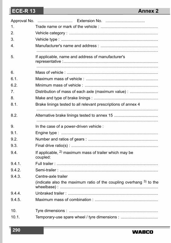
�����290
Approval No. ............................... Extension No. ...................................1. Trade name or mark of the vehicle : ...................................................2. Vehicle category : ...............................................................................3. Vehicle type : ......................................................................................4. Manufacturer's name and address : ...................................................
............................................................................................................5. If applicable, name and address of manufacturer's
representative :................................................................................................................................................................................................
6. Mass of vehicle : .................................................................................6.1. Maximum mass of vehicle : ................................................................6.2. Minimum mass of vehicle : .................................................................7. Distribution of mass of each axle (maximum value) : .........................8. Make and type of brake linings : .........................................................8.1. Brake linings tested to all relevant prescriptions of annex 4
............................................................................................................8.2. Alternative brake linings tested to annex 15 .......................................
............................................................................................................9. In the case of a power-driven vehicle :9.1. Engine type : ......................................................................................9.2. Number and ratios of gears : ..............................................................9.3. Final drive ratio(s) : .............................................................................
9.4. If applicable, 2) maximum mass of trailer which may becoupled:
9.4.1. Full trailer : ..........................................................................................9.4.2. Semi-trailer : .......................................................................................9.4.3. Centre-axle trailer
(indicate also the maximum ratio of the coupling overhang 3) to thewheelbase) : .......................................................................................
9.4.4. Unbraked trailer : ................................................................................9.4.5. Maximum mass of combination : ........................................................
10. Tyre dimensions : ...............................................................................10.1. Temporary-use spare wheel / tyre dimensions : .................................
Annex 2ECE-R 13

����� 291
10.2. Vehicle meets the technical requirements of annex 3 to Regulation No. 64 : Yes/No 2)
11. Number and arrangement of axles : ...................................................12. Brief description of braking equipment : .............................................
............................................................................................................13. Mass of vehicle when tested:
14. Results of the tests and vehicle characteristics:
Unladen (kg) Laden (kg)
king pin / supporting load
axle No. 1
axle No. 2
axle No. 3
axle No. 4
Total
Test Speed(km/h)
Measured performance
Measured force applied to
control (daN)
14.1 Type-0 tests, enginedisconnected : service braking
service braking
14.2 Type-0 tests, engine connected : service braking in accordance with paragraph 2.1.1. of annex 4
Annex 2 ECE-R 13

�����292
14.6. Braking system(s) used during the Type-II / IIA 2) test : ....................14.7. Reaction time and dimensions of flexible pipes : ................................14.7.1. Reaction time at the brake actuator : ............................................. s14.7.2. Reaction time at the control line coupling head : ............................ s14.7.3. Flexible pipes of tractors for semi-trailers :
length (m) : .........................................................................................internal diameter (mm) : ....................................................................
14.8. Information required under paragraph 7.3. of annex 10 to thisRegulation.
14.9. Vehicle is/is not 2) equipped to tow a trailer with electrical brakingsystems.
14.10. Vehicle is/is not 2) equipped with an anti-lock braking system.
14.10.1. The vehicle fulfils the requirement of annex 13: .................. Yes/No 2)
14.10.2. Category of anti-lock braking system: category 1 / 2 / 3 .................. 2) 5)
category A/B.......................... 2) 4)
14.3 Type-I tests: with repeated braking 5)
with continuousbraking 4) Free running,in accordance with annex 4, paragraph1.5.4. 5) and annex 4,paragraph 1.7.3. 4) respectively
14.4 Type-II or II-A 2) tests, as appropriateservice braking
14.5. Type-III tests 6)
Free running, in accord-ance with annex 4, para-graph 1.7.3.
Annex 2ECE-R 13

293
14.10.3. Vehicle is/is not 2) equipped to tow trailers equipped with anti-lockbraking system.
14.10.4. Where an annex 19 anti-lock test report has been utilised, the testreport number(s) shall be stated:
14.11. The vehicle is subject to the requirements of annex 5 (ADR): Yes/No2)
14.11.1. The vehicle fulfils the endurance braking performance requirementsaccording to the Type-IIA test up to a total maximum mass of .........tonnes: Yes/No2)
14.11.2. The power-driven vehicle is fitted with a control device for theendurance braking system on the trailer: Yes/No2)
14.11.3. In the case of trailers, the vehicle is equipped with an endurancebraking system: Yes/No2)
14.12. Vehicle is equipped with a control line(s) according to paragraphs5.1.3.1.1. / 5.1.3.1.2. / 5.1.3.1.3. 2)
14.13. Adequate documentation according to annex 18 was supplied inrespect of the following system(s):.................................. ................................................................................................ Yes / No / Not applicable 2)
15. Additional information for use with the annex 20 alternative typeapproval procedure.
15.1. Description of suspension: .................................................................15.1.1. Manufacturer: .....................................................................................15.1.2. Make: .................................................................................................15.1.3. Type: ..................................................................................................15.1.4. Model: ................................................................................................15.2. Wheelbase of vehicle tested: .............................................................15.3. Actuation differential (if any) within bogie: ..........................................
16. Trailer approved utilising annex 20 procedure: .................. Yes / No 2) (If yes, appendix 2 to this annex shall be completed)
17. Vehicle submitted for approval on ....................................................18. Technical service responsible for conducting approval tests ..............19. Date of report issued by that service ................................................20. Number of report issued by that service ..........................................
Annex 2 ECE-R 13

294
21. Approval granted/refused/extended/withdrawn 2)
22. Position of approval mark on the vehicle ............................................23. Place .................................................................................................24. Date ..................................................................................................25. Signature ..........................................................................................26. The summary referred to in paragraph 4.3. of this Regulation is
annexed to this communication.
Annex 2ECE-R 13
1) Distinguishing number of the country which has granted/extended/refused/withdrawn approval (see approval provisions in the Regulation).
2) Strike out what does not apply.3) ”Coupling overhang“ is the horizontal distance between the coupling for cen-
tre-axle trailers and the centreline of the rear axle(s)4) Applies only to vehicles of categories O2, and O3.5) Applies only to power-driven vehicles 6) Applies only to vehicles of category O4.

����� 295
Annex 2 - Appendix 1
LIST OF VEHICLE DATA FOR THE PURPOSE OF REGULATION No. 90 APPROVALS
1. Description of the vehicle type ............................................................1.1. Trade name or mark of the vehicle, if available...................................1.2. Vehicle category..................................................................................1.3. Vehicle type according to Regulation No. 13 approval........................
............................................................................................................1.4. Models or trade names of vehicles constituting the vehicle type, if
available ..........................................................................................................................................................................................................
1.5. Manufacturer's name and address......................................................2. Make and type of brake linings2.1. Brake linings tested to all relevant prescriptions of annex 4 ...............
............................................................................................................2.2. Brake linings tested to annex 15 .........................................................3. Minimum mass of vehicle....................................................................3.1. Distribution of mass of each axle (maximum value)............................
............................................................................................................4. Maximum mass of vehicle...................................................................4.1. Distribution of mass of each axle (maximum value)............................
............................................................................................................5. Maximum vehicle speed......................................................................6. Tyre and wheel dimensions.................................................................7. Brake circuit configuration (e.g. front/rear or diagonal split)................
............................................................................................................8. Declaration of which is the secondary braking system .......................
............................................................................................................
Annex 2 - Appendix 1 ECE-R 13

�����296
9. Specifications of brake valves (if applicable)...................................................................................................................................................
9.1. Adjustment specifications of the load sensing valve .......................................................................................................................................
9.2. Setting of pressure valve.....................................................................10. Designed brake force distribution........................................................11. Specification of brake ..........................................................................11.1. Disc brake type (e.g. number of pistons with diameter(s), ventilated
or solid disc) ........................................................................................11.2. Drum brake type (e.g. duo servo, with piston size and drum
dimensions) .........................................................................................11.3. In the case of compressed air brake systems, e.g. type and size of
chambers, levers, etc. .........................................................................12. Master cylinder type and size..............................................................13. Booster type and size..........................................................................
Annex 2 - Appendix 1ECE-R 13

����� 297
Annex 2 - Appendix 2
TYPE APPROVAL CERTIFICATE CONCERNING THEVEHICLE BRAKING EQUIPMENT
1. GeneralThe following additional items are to be recorded when the trailer hasbeen approved utilising the alternative procedure defined in annex 20to this Regulation.
2. Annex 19 test reports2.1. Diaphragm brake chambers: Report No. ..................................2.2. Spring Brakes: Report No. ..................................2.3. Trailer brake cold performance
characteristics: Report No. ..................................2.4. Anti-lock braking system: Report No. ..................................
3. Performance checks3.1. The trailer fulfils the requirements of annex 4, paragraphs 3.1.2. and
1.2.7 (service braking cold performance) Yes / No 2)
3.2. The trailer fulfils the requirements of annex 4, paragraph 3.2. (parkingbraking cold performance) Yes / No 2)
3.3. The trailer fulfils the requirements of annex 4, paragraph 3.3.(emergency/automatic braking performance) Yes / No 2)
3.4. The trailer fulfils the requirements of annex 10, paragraph 6. (brakingperformance in the case a failure in the braking distribution system)
Yes / No 2)
3.5. The trailer fulfils the requirements of paragraph 5.2.2.14.1. to thisRegulation (braking performance in the event of leakage fromauxiliary equipment) Yes / No 2)
3.6. The trailer fulfils the requirements of annex 13 (anti-lock braking) Yes / No 2)
Annex 2 - Appendix 2 ECE-R 13
2) Strike out what does not apply.

�����298
Annex 3
ARRANGEMENTS OF APPROVAL MARKS Model A
(See Paragraph 4.4. of this Regulation)
a = 8 mm min.The above approval mark affixed to a vehicle shows that the vehicle type concernedhas, with regard to braking, been approved in the United Kingdom (E 11) pursuantto Regulation No. 13 under approval number 092439. This number indicates that theapproval was given in accordance with the requirements of Regulation No. 13 withthe 09 series of amendments incorporated. For vehicles of categories M2 and M3,this mark means that that type of vehicle has undergone the Type-II test.
Model B(See Paragraph 4.5. of this Regulation)
a =8 mm min.The above approval mark affixed to a vehicle shows that the vehicle type concernedhas, with regard to braking, been approved in the United Kingdom (E 11) pursuantto Regulation No. 13. For vehicles of Categories M2 and M3, this mark means thatthe type of vehicle has undergone the Type-II A test.
a E 11 a/3 a/2 13R - 09 2439 a/3
a E 11 a/3 a/2 13RM - 09 2439 a/3
Annex 3ECE-R 13

����� 299
Model C(See Paragraph 4.6. of this Regulation)
a = 8 mm min.
The above approval mark affixed to a vehicle shows that the vehicle type concernedhas been approved in the United Kingdom (E 11) pursuant to Regulation Nos. 13 and 24 1). (In the case of the latter Regulation the corrected absorption coefficient is 1.30 m -1.)
a E 11 a/3 a/213 09 2439
02 162824 1.30
a/3
a/3
a/2
a/2
Annex 3 ECE-R 13
1) This number is given merely as an example.
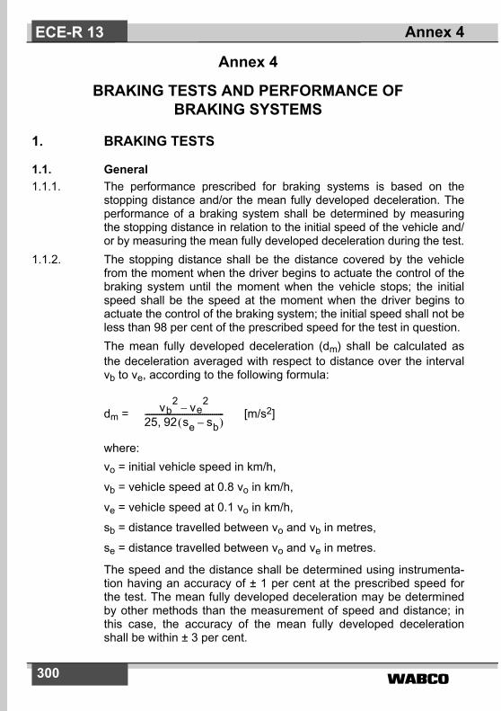
�����300
Annex 4
BRAKING TESTS AND PERFORMANCE OF BRAKING SYSTEMS
1. BRAKING TESTS
1.1. General1.1.1. The performance prescribed for braking systems is based on the
stopping distance and/or the mean fully developed deceleration. Theperformance of a braking system shall be determined by measuringthe stopping distance in relation to the initial speed of the vehicle and/or by measuring the mean fully developed deceleration during the test.
1.1.2. The stopping distance shall be the distance covered by the vehiclefrom the moment when the driver begins to actuate the control of thebraking system until the moment when the vehicle stops; the initialspeed shall be the speed at the moment when the driver begins toactuate the control of the braking system; the initial speed shall not beless than 98 per cent of the prescribed speed for the test in question.The mean fully developed deceleration (dm) shall be calculated asthe deceleration averaged with respect to distance over the intervalvb to ve, according to the following formula:
dm = [m/s2]
where:vo = initial vehicle speed in km/h,
vb = vehicle speed at 0.8 vo in km/h,
ve = vehicle speed at 0.1 vo in km/h,
sb = distance travelled between vo and vb in metres,
se = distance travelled between vo and ve in metres.
The speed and the distance shall be determined using instrumenta-tion having an accuracy of ± 1 per cent at the prescribed speed forthe test. The mean fully developed deceleration may be determinedby other methods than the measurement of speed and distance; inthis case, the accuracy of the mean fully developed decelerationshall be within ± 3 per cent.
vb2 ve
2–
25 92 se sb–� �,----------------------------------------
Annex 4ECE-R 13
����� 301
1.2. For the approval of any vehicle, the braking performance shall bemeasured during road tests conducted in the following conditions:
1.2.1. the vehicle's condition as regards mass must be as prescribed foreach type of test and be specified in the test report;
1.2.2. the test must be carried out at the speeds prescribed for each type oftest; if the maximum design speed of a vehicle is lower than thespeed prescribed for a test, the test shall be performed at thevehicle's maximum speed;
1.2.3. during the tests, the force applied to the brake control of the brakingsystem in order to obtain the prescribed performance must notexceed the maximum force laid down for the test vehicle's category;
1.2.4. the road must have a surface affording good adhesion, unlessspecified otherwise in the relevant annexes;
1.2.5. the tests must be performed when there is no wind liable to affect theresults;
1.2.6. at the start of the tests, the tyres must be cold and at the pressureprescribed for the load actually borne by the wheels when the vehicleis stationary;
1.2.7. the prescribed performance must be obtained without locking of thewheels, without deviation of the vehicle from its course, and withoutabnormal vibration. 1)
1.2.8. For vehicles powered completely or partially by an electric motor (ormotors), permanently connected to the wheels, all tests must becarried out with the motor(s) connected.
1.2.9. For vehicles as described in paragraph 1.2.8. above, fitted with anelectric regenerative braking system of category A, behaviour testsdefined in paragraph 1.4.3.1. of this annex shall be carried out on atrack with a low adhesion coefficient (as defined in paragraph 5.2.2.of annex 13).
1.2.9.1. Moreover, for vehicles fitted with an electric regenerative brakingsystem of category A, transient conditions as gear changes oraccelerator control release shall not affect the behaviour of thevehicle in condition of tests described in paragraph 1.2.9.
1.2.10. During the tests specified in paragraphs 1.2.9. and 1.2.9.1., wheellocking is not allowed. However, steering correction is permitted ifthe angular rotation of the steering control is within 120° during theinitial 2 seconds and not more than 240° in total.
Annex 4 ECE-R 13
1) Wheel locking is permitted where specifically mentioned.

�����302
1.2.11. For a vehicle with electrically actuated service brakes powered fromtraction batteries (or an auxiliary battery) which receive(s) energyonly from an independent external charging system, these batteriesshall, during braking performance testing, be at an average of notmore than 5 per cent above that state of charge at which the brakefailure warning prescribed in paragraph 5.2.1.27.6. is required to begiven.If this warning is given, the batteries may receive some rechargeduring the tests, to keep them in the required state of charge range.
1.3. Behaviour of the vehicle during braking.1.3.1. In braking tests, and in particular in those at high speed, the general
behaviour of the vehicle during braking must be checked.1.3.2. Behaviour of the vehicle during braking on a road on which adhesion
is reduced. The behaviour of vehicles of categories M1, M2, M3, N1,N2, N3, O2, O3 and O4 on a road on which adhesion is reduced, mustmeet the relevant requirements of annex 10 and/or annex 13 to thisRegulation.
1.3.2.1. In the case of a braking system according to paragraph 5.2.1.7.2.,where the braking for a particular axle (or axles) is comprised of morethan one source of braking torque, and any individual source can bevaried with respect to the other(s), the vehicle shall satisfy therequirements of annex 10, or alternatively, annex 13 under allrelationships permitted by its control strategy. 2)
1.4. Type-0 test (ordinary performance test with brakes cold)1.4.1. General1.4.1.1. The brakes must be cold; a brake is deemed to be cold when the
temperature measured on the disc or on the outside of the drum isbelow 100° C.
1.4.1.2. The test must be conducted on the following conditions:1.4.1.2.1. the vehicle must be laden, the distribution of its mass among the
axles being that stated by the manufacturer; where provision is madefor several arrangements of the load on the axles the distribution ofthe maximum mass among the axles must be such that the load oneach axle is proportional to the maximum permissible load for eachaxle. In the case of tractors for semi-trailers, the load may be re-
Annex 4ECE-R 13
2) The manufacturer shall provide the Technical Service with the family of brak-ing curves permitted by the automatic control strategy employed. Thesecurves may be verified by the Technical Service.

����� 303
positioned approximately half-way between the kingpin positionresulting from the above loading conditions and the centreline of therear axle(s),
1.4.1.2.2. every test must be repeated on the unladen vehicle. In the case of apower-driven vehicle there may be, in addition to the driver, a secondperson on the front seat who is responsible for noting the results ofthe test;in the case of a tractor for a semi-trailer, the unladen tests will beconducted with the vehicle in its solo condition, including a massrepresenting the fifth wheel. It will also include a mass representing aspare wheel, if this is included in the standard specification of thevehicle,in the case of a vehicle presented as a bare chassis-cab, asupplementary load may be added to simulate the mass of the body,not exceeding the minimum mass declared by the manufacturer inannex 2 to this RegulationIn the case of a vehicle equipped with an electric regenerativebraking system, the requirements depend on the category of thissystem:Category A. Any separate electric regenerative braking control
which is provided, shall not be used during the Type-0tests.
Category B. The contribution of the electric regenerative brakingsystem to the braking force generated shall notexceed that minimum level guaranteed by the systemdesign.
This requirement is deemed to be satisfied if the batteries are at oneof the following state of charge conditions were state of charge 3) isdetermined by the method set out in appendix 1 to this annex:at the maximum charge level as recommended by the manufacturerin the vehicle specification, orat a level not less than 95 per cent of the full charge level, where themanufacturer has made no specific recommendation, or at themaximum level which results from automatic charge control on thevehicle.
1.4.1.2.3. the limits prescribed for minimum performance, both for tests with thevehicle unladen and for tests with the vehicle laden, shall be those
Annex 4 ECE-R 13
3) By agreement with the technical service, state of charge assessment will notbe required for vehicles, which have an on-board energy source for chargingthe traction batteries and the means for regulating their state of charge.
�����304
laid down hereunder for each category of vehicles; the vehicle mustsatisfy both the prescribed stopping distance and the prescribedmean fully developed deceleration for the relevant vehicle category,but it may not be necessary to actually measure both parameters.
1.4.1.2.4. The road must be level.
1.4.2. Type-0 test with engine disconnected.The test must be carried out at the speed prescribed for the categoryto which the vehicle belongs, the figures prescribed in this connectionbeing subject to a certain margin of tolerance. The minimum perfor-mance prescribed for each category must be attained.
1.4.3. Type-0 test with engine connected.1.4.3.1. Tests must also be carried out at various speeds, the lowest being
equal to 30 per cent of the maximum speed of the vehicle and thehighest being equal to 80 per cent of that speed. In the case ofvehicles equipped with a speed limiter, this limiter speed shall betaken as the maximum speed of the vehicle. The maximum practicalperformance figures shall be measured and the behaviour of thevehicle shall be recorded in the test report. Tractors for semi-trailers,artificially loaded to simulate the effects of a laden semi-trailer shallnot be tested beyond 80 km/h.
1.4.3.2. Further tests shall be carried out with the engine connected, from thespeed prescribed for the category to which the vehicle belongs. Theminimum performance prescribed for each category must beattained. Tractive units for semi-trailers, artificially loaded to simulatethe effects of a laden semi-trailer shall not be tested beyond 80 km/h.
1.4.4. Type-0 test for vehicles of category O, equipped with compressed airbrakes.
1.4.4.1. The braking performance of the trailer can be calculated either fromthe braking rate of the towing vehicle plus the trailer and themeasured thrust on the coupling or, in certain cases, from the brakingrate of the towing vehicle plus the trailer with only the trailer beingbraked. The engine of the towing vehicle must be disconnectedduring the braking test.In the case where only the trailer is braked, to take account of theextra mass being retarded, the performance will be taken to be themean fully developed deceleration.
1.4.4.2. With the exception of cases according to paragraphs 1.4.4.3. and1.4.4.4. of this annex, it is necessary for the determination of thebraking rate of the trailer to measure the braking rate of the towing
Annex 4ECE-R 13
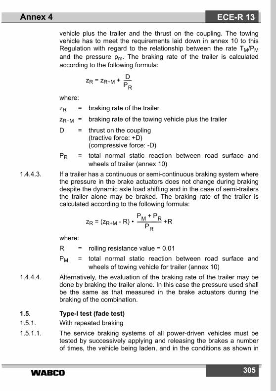
����� 305
vehicle plus the trailer and the thrust on the coupling. The towingvehicle has to meet the requirements laid down in annex 10 to thisRegulation with regard to the relationship between the rate TM/PMand the pressure pm. The braking rate of the trailer is calculatedaccording to the following formula:
zR = zR+M +
where:zR = braking rate of the trailer
zR+M = braking rate of the towing vehicle plus the trailer
D = thrust on the coupling(tractive force: +D)(compressive force: -D)
PR = total normal static reaction between road surface andwheels of trailer (annex 10)
1.4.4.3. If a trailer has a continuous or semi-continuous braking system wherethe pressure in the brake actuators does not change during brakingdespite the dynamic axle load shifting and in the case of semi-trailersthe trailer alone may be braked. The braking rate of the trailer iscalculated according to the following formula:
zR = (zR+M - R) • +R
where:R = rolling resistance value = 0.01PM = total normal static reaction between road surface and
wheels of towing vehicle for trailer (annex 10)1.4.4.4. Alternatively, the evaluation of the braking rate of the trailer may be
done by braking the trailer alone. In this case the pressure used shallbe the same as that measured in the brake actuators during thebraking of the combination.
1.5. Type-I test (fade test)1.5.1. With repeated braking1.5.1.1. The service braking systems of all power-driven vehicles must be
tested by successively applying and releasing the brakes a numberof times, the vehicle being laden, and in the conditions as shown in
DPR-------
PM PR+PR
----------------------
Annex 4 ECE-R 13

�����306
the table below:
where:v1 = initial speed, at beginning of braking
v2 = speed at end of braking
vmax = maximum speed of vehicle
n = number of brake applications�t = duration of a braking cycle: time elapsing between the
initiation of one brake application and the initiation of the next.
1.5.1.2. If the characteristics of the vehicle make it impossible to abide by theduration prescribed for �t, the duration may be increased; in anyevent, in addition to the time necessary for braking and acceleratingthe vehicle, a period of 10 seconds must be allowed in each cycle forstabilizing the speed v1.
1.5.1.3. In these tests, the force applied to the control must be so adjusted asto attain the mean fully developed deceleration of 3 m/s2 at the firstbrake application; this force must remain constant throughout thesucceeding brake applications.
1.5.1.4. During brake applications, the highest gear ratio (excludingoverdrive, etc.) must be continuously engaged.
1.5.1.5. For regaining speed after braking, the gearbox must be used in sucha way as to attain the speed v1 in the shortest possible time(maximum acceleration allowed by the engine and gearbox).
Category ofvehicles
Conditions
v1[km/h]
v2[km/h]
�t[sec] n
M180 % vmax
� 120 ½ v1 45 15
M280 % vmax
� 100 ½ v1 55 15
N180 % vmax
� 120 ½ v1 55 15
M3, N2, N380 % vmax
� 60 ½ v1 60 20
Annex 4ECE-R 13

����� 307
1.5.1.6. For vehicles not having sufficient autonomy to carry out the cycles ofheating of the brakes, the tests shall be carried out by achieving theprescribed speed before the first braking application and thereafterby using the maximum acceleration available to regain speed andthen braking successively at the speed reached at the end of eachtime cycle duration as specified, for the appropriate vehicle category,in paragraph 1.5.1.1. above.
1.5.1.7. For vehicles equipped with an electric regenerative braking system ofcategory B, the condition of the vehicle batteries at the start of thetest, shall be such that the braking force contribution provided by theelectric regenerative braking system does not exceed the minimumguaranteed by the system design. This requirement is deemed to be satisfied if the batteries are at oneof the state of charge conditions listed in the fourth clause ofparagraph 1.4.1.2.2. above.
1.5.1.7.1. In the case of vehicles equipped with air operated brakes theadjustment of the brakes shall be such as to enable the automaticbrake adjustment device to function. For this purpose the actuatorstroke shall be adjusted toso � 1.1 × sre-adjust (the upper limit shall not exceed a valuerecommended by the manufacturer)where:
sre-adjust is the re-adjustment stroke according to thespecification of the manufacturer of the automaticbrake adjustment device, i.e. the stroke, where it startsto readjust the running clearance of the brake with anactuator pressure of 15 per cent of the brake systemoperating pressure but not less than 1.0 bar.
Where, by agreement with the Technical Service, it is impractical tomeasure the actuator stroke, the initial setting shall be agreed withthe Technical Service.From the above condition the brake shall be operated with anactuator pressure of 30 per cent of the brake system operatingpressure but not less than 2.0 bar, 50 times in succession. This shallbe followed by a single brake application with an actuator pressure of� 6.5 bar.
1.5.1.7.2. In the case of vehicles equipped with hydraulically operated discbrakes no setting requirements are deemed necessary.
1.5.1.7.3. In the case of vehicles equipped with hydraulically operated drumbrakes the adjustment of the brakes shall be as specified by themanufacturer.
Annex 4 ECE-R 13
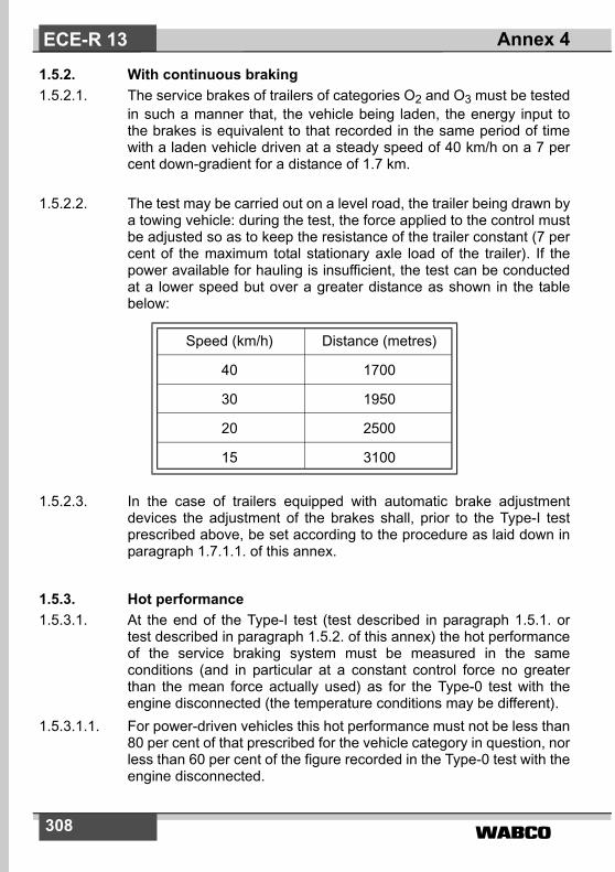
�����308
1.5.2. With continuous braking1.5.2.1. The service brakes of trailers of categories O2 and O3 must be tested
in such a manner that, the vehicle being laden, the energy input tothe brakes is equivalent to that recorded in the same period of timewith a laden vehicle driven at a steady speed of 40 km/h on a 7 percent down-gradient for a distance of 1.7 km.
1.5.2.2. The test may be carried out on a level road, the trailer being drawn bya towing vehicle: during the test, the force applied to the control mustbe adjusted so as to keep the resistance of the trailer constant (7 percent of the maximum total stationary axle load of the trailer). If thepower available for hauling is insufficient, the test can be conductedat a lower speed but over a greater distance as shown in the tablebelow:
1.5.2.3. In the case of trailers equipped with automatic brake adjustmentdevices the adjustment of the brakes shall, prior to the Type-I testprescribed above, be set according to the procedure as laid down inparagraph 1.7.1.1. of this annex.
1.5.3. Hot performance1.5.3.1. At the end of the Type-I test (test described in paragraph 1.5.1. or
test described in paragraph 1.5.2. of this annex) the hot performanceof the service braking system must be measured in the sameconditions (and in particular at a constant control force no greaterthan the mean force actually used) as for the Type-0 test with theengine disconnected (the temperature conditions may be different).
1.5.3.1.1. For power-driven vehicles this hot performance must not be less than80 per cent of that prescribed for the vehicle category in question, norless than 60 per cent of the figure recorded in the Type-0 test with theengine disconnected.
Speed (km/h) Distance (metres)
40 1700
30 1950
20 2500
15 3100
Annex 4ECE-R 13

����� 309
1.5.3.1.2. For vehicles fitted with an electric regenerative braking system ofcategory A, during brake applications, the highest gear shall becontinuously engaged and the separate electric regenerative brakingcontrol, if any, shall not be used.
1.5.3.1.3. In the case of vehicles equipped with an electric regenerative brakingsystem of category B, having carried out the heating cycles accordingto paragraph 1.5.1.6. of this annex, the hot performance test shall becarried out at the maximum speed which can be reached by thevehicle at the end of the brake heating cycles, unless the speedspecified in paragraph 1.4.2. of this annex can be reached.For comparison, the Type-0 test with cold brakes shall be repeatedfrom this same speed and with a similar electric regenerative brakingcontribution, as set by an appropriate state of battery charge, as wasavailable during the hot performance test.Reconditioning of the linings shall be permitted before the test ismade to compare this second Type-0 cold performance with thatachieved in the hot test, against the criteria of paragraphs 1.5.3.1.1.and 1.5.3.2. of this annex.
1.5.3.1.4. However, in the case of trailers, the hot brake force at the peripheryof the wheels, when tested at 40 km/h, must not be less than 36 percent of the maximum stationary wheel load, nor less than 60 per centof the figure recorded in the Type-0 test at the same speed.
1.5.3.2. In the case of a power-driven vehicle which satisfies the 60 per centrequirement specified in paragraph 1.5.3.1.1. above, but whichcannot comply with the 80 per cent requirement of paragraph1.5.3.1.1. above, a further hot performance test may be carried outusing a control force not exceeding that specified in paragraph 2. ofthis annex for the relevant vehicle category. The results of both testsshall be entered in the report.
1.5.4. Free running testIn the case of motor vehicles equipped with automatic brakeadjustment devices, the brakes after completing the tests defined inparagraph 1.5.3 above will be allowed to cool to a temperaturerepresentative of a cold brake (i.e. ��100°C) and it shall be verifiedthat the vehicle is capable of free running by fulfilling one of thefollowing conditions:a) Wheels are running freely (i.e. may be rotated by hand)b) It is ascertained that when the vehicle is driven at a constant
speed of v = 60 km/h with the brakes released the asymptotic
Annex 4 ECE-R 13

�����310
temperatures shall not exceed a drum/disc temperatureincrease of 80°C, then the residual brake moments areregarded as acceptable.
1.6. Type-II test (downhill behaviour test)1.6.1. Laden power-driven vehicles must be tested in such a manner that
the energy input is equivalent to that recorded in the same period oftime with a laden vehicle driven at an average speed of 30 km/h on a6 per cent down-gradient for a distance of 6 km, with the appropriategear engaged and the Endurance braking system, if the vehicle isequipped with one, being used. The gear engaged must be such thatthe speed of the engine (min-1) does not exceed the maximum valueprescribed by the manufacturer.
1.6.2. For vehicles in which the energy is absorbed by the braking action ofthe engine alone, a tolerance of ± 5 km/h on the average speed shallbe permitted, and the gear enabling the speed to be stabilized at thevalue closest to 30 km/h on the 6 per cent down-gradient shall beengaged. If the performance of the braking action of the engine aloneis determined by a measurement of deceleration, it shall be sufficientif the mean deceleration measured is at least 0.5 m/s2.
1.6.3. At the end of the test, the hot performance of the service brakingsystem must be measured in the same conditions as for the Type-0test with the engine disconnected (the temperature conditions maybe different). This hot performance must give a stopping distance notexceeding the following values and a mean fully developeddeceleration not less than the following values, using a control forcenot exceeding 70 daN,
category M3 s = 0.15 v + (1.33 v2/130) (the second term corre-sponds to a mean fully developed deceleration dm = 3.75 m/s2)
category N3 s = 0.15 v + (1.33 v2/115) (the second term corre-sponds to a mean fully developed deceleration dm = 3.3 m/s2)
1.6.4. Vehicles cited in paragraphs 1.8.1.1., 1.8.1.2. and 1.8.1.3. belowmust satisfy the Type-IIA test described in paragraph 1.8. belowinstead of the Type-II test.
Annex 4ECE-R 13

����� 311
1.7. Type-III test (fade test for vehicles of category O4)1.7.1. Track test1.7.1.1. The adjustment of the brakes shall, prior to the Type-III test below, be
set according to the following procedures as appropriate:1.7.1.1.1. In the case of trailers equipped with air operated brakes the
adjustment of the brakes shall be such as to enable the automaticbrake adjustment device to function. For this purpose the actuatorstroke shall be adjusted toso � 1.1 × sre-adjust (the upper limit shall not exceed a value recom-mended by the manufacturer)where:sre-adjust is the re-adjustment stroke according to the
specification of the manufacturer of the automaticbrake adjustment device, i.e. the stroke, where it startsto re-adjust the running clearance of the brake with anactuator pressure of 1.0 bar.
Where, by agreement with the Technical Service, it is impractical tomeasure the actuator stroke, the initial setting shall be agreed withthe Technical Service.From the above condition the brake shall be operated with anactuator pressure of 2.0 bar, 50 times in succession. This shall befollowed by a single brake application with an actuator pressure of� 6.5 bar.
1.7.1.1.2. In the case of trailers equipped with hydraulically operated discbrakes no setting requirements are deemed necessary.
1.7.1.1.3. In the case of trailers equipped with hydraulically operated drumbrakes the adjustment of the brakes shall be as specified by themanufacturer.
1.7.1.2. For the road test the conditions shall be as follows:number of brake applications: 20duration of a braking cycle: 60 sinitial speed at the beginning of braking: 60 km/hbraking applications: In these tests, the force applied to the control
must be so adjusted as to attain the mean fullydeveloped deceleration of 3 m/s2 in respect tothe trailer mass PR at the first brake applica-tion; this force must remain constant through-out the succeeding brake applications.
Annex 4 ECE-R 13
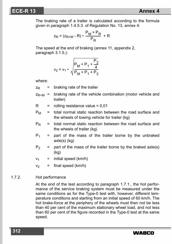
�����312
The braking rate of a trailer is calculated according to the formulagiven in paragraph 1.4.5.3. of Regulation No. 13, annex 4:
zR = (zR+M - R) • + R
The speed at the end of braking (annex 11, appendix 2, paragraph 3.1.5.):
v2 = v1 •
where:zR = braking rate of the trailer
zR+M = braking rate of the vehicle combination (motor vehicle andtrailer)
R = rolling resistance value = 0,01PM = total normal static reaction between the road surface and
the wheels of towing vehicle for trailer (kg)PR = total normal static reaction between the road surface and
the wheels of trailer (kg)P1 = part of the mass of the trailer borne by the unbraked
axle(s) (kg)P2 = part of the mass of the trailer borne by the braked axle(s)
(kg)v1 = initial speed (km/h)
v2 = final speed (km/h)
1.7.2. Hot performance
At the end of the test according to paragraph 1.7.1., the hot perfor-mance of the service braking system must be measured under thesame conditions as for the Type-0 test with, however, different tem-perature conditions and starting from an initial speed of 60 km/h. Thehot brake-force at the periphery of the wheels must then not be lessthan 40 per cent of the maximum stationary wheel load, and not lessthan 60 per cent of the figure recorded in the Type-0 test at the samespeed.
PM PR+PR
----------------------
PM P1P24
-------+ +
PM P1 P2+ +-----------------------------------
Annex 4ECE-R 13
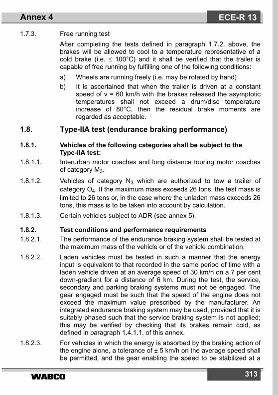
����� 313
1.7.3. Free running testAfter completing the tests defined in paragraph 1.7.2, above, thebrakes will be allowed to cool to a temperature representative of acold brake (i.e. � 100°C) and it shall be verified that the trailer iscapable of free running by fulfilling one of the following conditions:a) Wheels are running freely (i.e. may be rotated by hand)b) It is ascertained that when the trailer is driven at a constant
speed of v = 60 km/h with the brakes released the asymptotictemperatures shall not exceed a drum/disc temperatureincrease of 80°C, then the residual brake moments areregarded as acceptable.
1.8. Type-IIA test (endurance braking performance)
1.8.1. Vehicles of the following categories shall be subject to the Type-IIA test:
1.8.1.1. Interurban motor coaches and long distance touring motor coachesof category M3.
1.8.1.2. Vehicles of category N3 which are authorized to tow a trailer ofcategory O4. If the maximum mass exceeds 26 tons, the test mass islimited to 26 tons or, in the case where the unladen mass exceeds 26tons, this mass is to be taken into account by calculation.
1.8.1.3. Certain vehicles subject to ADR (see annex 5).
1.8.2. Test conditions and performance requirements1.8.2.1. The performance of the endurance braking system shall be tested at
the maximum mass of the vehicle or of the vehicle combination.1.8.2.2. Laden vehicles must be tested in such a manner that the energy
input is equivalent to that recorded in the same period of time with aladen vehicle driven at an average speed of 30 km/h on a 7 per centdown-gradient for a distance of 6 km. During the test, the service,secondary and parking braking systems must not be engaged. Thegear engaged must be such that the speed of the engine does notexceed the maximum value prescribed by the manufacturer. Anintegrated endurance braking system may be used, provided that it issuitably phased such that the service braking system is not applied;this may be verified by checking that its brakes remain cold, asdefined in paragraph 1.4.1.1. of this annex.
1.8.2.3. For vehicles in which the energy is absorbed by the braking action ofthe engine alone, a tolerance of ± 5 km/h on the average speed shallbe permitted, and the gear enabling the speed to be stabilized at a
Annex 4 ECE-R 13
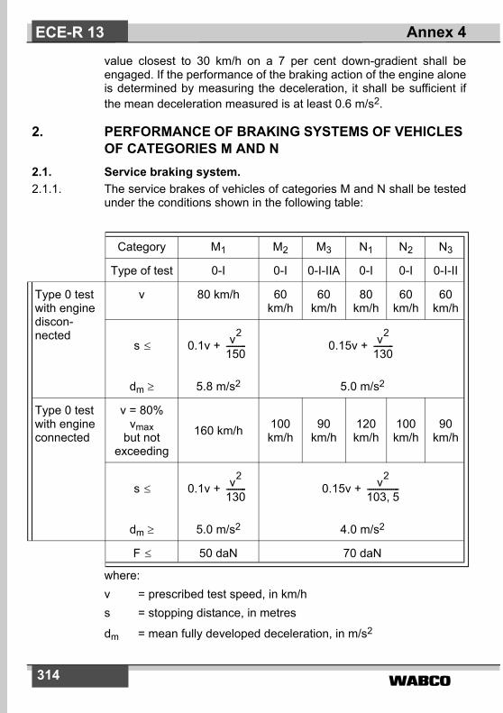
�����314
value closest to 30 km/h on a 7 per cent down-gradient shall beengaged. If the performance of the braking action of the engine aloneis determined by measuring the deceleration, it shall be sufficient ifthe mean deceleration measured is at least 0.6 m/s2.
2. PERFORMANCE OF BRAKING SYSTEMS OF VEHICLES OF CATEGORIES M AND N
2.1. Service braking system.2.1.1. The service brakes of vehicles of categories M and N shall be tested
under the conditions shown in the following table:
where: v = prescribed test speed, in km/hs = stopping distance, in metres
dm = mean fully developed deceleration, in m/s2
Category M1 M2 M3 N1 N2 N3
Type of test 0-I 0-I 0-I-IIA 0-I 0-I 0-I-II
Type 0 testwith enginediscon-nected
v 80 km/h 60 km/h
60 km/h
80 km/h
60 km/h
60 km/h
s �
dm �
0.1v +
5.8 m/s2
0.15v +
5.0 m/s2
Type 0 testwith engineconnected
v = 80%vmax
but not exceeding
160 km/h 100km/h
90km/h
120km/h
100km/h
90km/h
s �
dm �
0.1v +
5.0 m/s2
0.15v +
4.0 m/s2
F � 50 daN 70 daN
v2
150---------- v2
130----------
v2
130---------- v2
103 5,----------------
Annex 4ECE-R 13

����� 315
F = force applied to foot control, in daNvmax = maximum speed of the vehicle, in km/h
2.1.2. In the case of a power-driven vehicle authorized to tow an unbrakedtrailer, the minimum performance prescribed for the correspondingpower-driven vehicle category (for the Type-0 test with enginedisconnected) must be attained with the unbraked trailer coupled tothe power-driven vehicle and with the unbraked trailer laden to themaximum mass declared by the power-driven vehicle manufacturer.However, in the case of category M1 vehicles, the minimumcombination performance shall be not less than 5.4 m/s2 both inladen and unladen conditions.
The combination performance shall be verified by calculations refer-ring to the maximum braking performance actually achieved by thepower-driven vehicle alone (laden) during the Type-0 test with theengine disconnected, using the following formula (no practical testswith a coupled unbraked trailer are required):
dM + R = dM •
where:dM + R = calculated mean fully developed deceleration of the
power-driven vehicle when coupled to an unbraked trailer,in m/s2
dM = maximum mean fully developed deceleration of the power-driven vehicle alone achieved during the Type-0 test withengine disconnected, in m/s2
PM = mass of the power-driven vehicle (laden),
PR = maximum mass of an unbraked trailer which may be cou-pled, as declared by the power-driven vehicle manufacturer.
2.2. Secondary braking system2.2.1. The secondary braking system, even if the control which actuates is
also used for other braking functions, must give a stopping distancenot exceeding the following values and a mean fully developeddeceleration not less than the following values:
Category M1 s = 0.1 v + (2 v2/150) (the second term corresponds to a mean fully developed deceleration
dm = 2.9 m/s2)
PMPM PR+----------------------
Annex 4 ECE-R 13

�����316
Category M2, M3 s = 0.15 v + (2 v2/130) (the second termcorresponds to a mean fully developeddeceleration dm = 2.5 m/s2)
Category N s = 0.15 v + (2 v2/115) (the second termcorresponds to a mean fully developeddeceleration dm = 2.2 m/s2)
2.2.2. If the control is manual, the prescribed performance must beobtained by applying to the control a force not exceeding 40 daN inthe case of vehicles of category M1 and 60 daN in the case of othervehicles, and the control must be so placed that it can be easily andquickly grasped by the driver.
2.2.3. If it is a foot control, the prescribed performance must be obtained byapplying to the control a force not exceeding 50 daN in the case ofvehicles of category M1, and 70 daN in the case of other vehicles,and the control must be so placed that it can be easily and quicklyactuated by the driver.
2.2.4. The performance of the secondary braking system must be checkedby the Type-0 test with engine disconnected from the following initialspeeds:M1 : 80 km/h M2 : 60 km/h M3 : 60 km/hN1 : 70 km/h N2 : 50 km/h N3 : 40 km/h
2.2.5. The secondary braking effectiveness test shall be conducted bysimulating the actual failure conditions in the service braking system.
2.2.6. For vehicles employing electric regenerative braking systems, thebraking performance shall additionally be checked under the twofollowing failure conditions:
2.2.6.1. For a total failure of the electric component of the service brakingoutput.
2.2.6.2. In the case where the failure condition causes the electric componentto deliver its maximum braking force.
2.3. Parking braking system.2.3.1. The parking braking system must, even if it is combined with one of
the other braking systems, be capable of holding the laden vehiclestationary on an 18 per cent up or down-gradient.
2.3.2. On vehicles to which the coupling of a trailer is authorized, theparking braking system of the towing vehicle must be capable ofholding the combination of vehicles stationary on a 12 per cent up ordown-gradient.
Annex 4ECE-R 13

����� 317
2.3.3. If the control device is manual, the force applied to it must not exceed40 daN in the case of vehicles of category M1, and 60 daN in thecase of all other vehicles.
2.3.4. If it is a foot control, the force exerted on the control must not exceed50 daN in the case of vehicles of category M1, and 70 daN in thecase of all other vehicles.
2.3.5. A parking braking system which has to be actuated several timesbefore it attains the prescribed performance is admissible.
2.3.6. To check compliance with the requirement specified in paragraph5.2.1.2.4. of this Regulation, a Type-0 test must be carried out withthe engine disconnected at an initial test speed of 30 km/h. The meanfully developed deceleration on application of the control of theparking brake system and the deceleration immediately before thevehicle stops shall not be less than 1.5 m/s2. The test shall be carriedout with the laden vehicle. The force exerted on the braking controldevice shall not exceed the specified values.
2.4. Residual braking after transmission failure.2.4.1. The residual performance of the service braking system, in the event
of failure in a part of its transmission, must give a stopping distancenot exceeding the following values and a mean fully developeddeceleration not less than the following values, using a control forcenot exceeding 70 daN, when checked by the Type-0 test with theengine disconnected from the following initial speeds for the relevantvehicle category:Stopping distance (m) and mean fully developed deceleration (m/s2)
Annex 4 ECE-R 13

�����318
2.4.2. The residual braking effectiveness test shall be conducted bysimulating the actual failure conditions in the service braking system.
3. PERFORMANCE OF BRAKING SYSTEMS OF VEHICLES OF CATEGORY O
3.1. Service braking system.3.1.1. Provision relating to tests of vehicles of category O1:
Where the provision of a service braking system is mandatory, theperformance of the system must meet the requirements laid down forvehicles of categories O2 and O3.
3.1.2. Provisions relating to tests of vehicles of categories O2 and O3.
3.1.2.1. If the service braking system is of the continuous or semi-continuoustype, the sum of the forces exerted on the periphery of the brakedwheels shall be at least x per cent of the maximum stationary wheelload, x having the following values:
x [%]full trailer, laden and unladen : 50semi-trailer, laden and unladen : 45centre-axle trailer, laden and unladen : 50
Type v1 in(km/h)
s (m)LADEN
dm inm/s2
s (m)UNLADEN
dm inm/s2
M1 80 0.10v + • 1.7 0.10v + • 1.5
M2 60 0.15v + • 1.5 0.15v + • 1.3
M3 60 0.15v + • 1.5 0.15v + • 1.5
N1 70 0.15v + • 1.3 0.15v + • 1.1
N2 50 0.15v + • 1.3 0.15v + • 1.1
N3 40 0.15v + • 1.3 0.15v + • 1.3
10030
---------- v2
150------- 100
25---------- v2
150-------
10030
---------- v2
130------- 100
25---------- v2
130-------
10030
---------- v2
130------- 100
30---------- v2
130-------
10030
---------- v2
115------- 100
25---------- v2
115-------
10030
---------- v2
115------- 100
25---------- v2
115-------
10030
---------- v2
115------- 100
30---------- v2
115-------
Annex 4ECE-R 13

����� 319
3.1.2.2. If the trailer is fitted with a compressed-air braking system, thepressure in the supply line shall not exceed 7,0 bar during the braketest and the signal value in the control line shall not exceed thefollowing values, depending on the installation:(a) 6.5 bar in the pneumatic control line;(b) a digital demand value corresponding to 6.5 bar (as defined in
ISO 11992: 2003) in the electric control line.
The test speed is 60 km/h. A supplementary test at 40 km/h shall becarried out with the laden trailer for comparison with the Type-I testresult.
3.1.2.3. lf the braking system is of the inertia type, it must comply with therequirements of annex 12 to this Regulation.
3.1.2.4. In addition, the vehicles must undergo the Type-I test.3.1.2.5. In the Type-I test of a semi-trailer, the mass braked by the latter's
axle(s) must correspond to the maximum axle load(s) (not includingking-pin load).
3.1.3. Provisions relating to tests of vehicles of category O4.
3.1.3.1. If the service braking system is of the continuous or semi-continuoustype, the sum of the forces exerted on the periphery of the brakedwheels shall be at least x per cent of the maximum stationary wheelload, x having the following values:full trailer, laden and unladen : 50semi-trailer, laden and unladen : 45centre-axle trailer, laden and unladen: 50
3.1.3.2. If the trailer is fitted with a compressed air braking system, thepressure in the control line must not exceed 6.5 bar and the pressurein the supply line must not exceed 7.0 bar during the brake test. Thetest speed is 60 km/h.
3.1.3.3. In addition, the vehicles must undergo the Type-III test.3.1.3.4. In the Type-III test of a semi-trailer, the mass braked by the latter's
axle(s) must correspond to the maximum axle load(s).
3.2. Parking braking system.3.2.1. The parking braking system with which the trailer is equipped must
be capable of holding the laden trailer stationary, when separatedfrom the towing vehicle, on an 18 per cent up or down-gradient. Theforce applied to the control device must not exceed 60 daN.
Annex 4 ECE-R 13
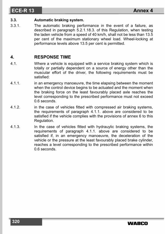
�����320
3.3. Automatic braking system.3.3.1. The automatic braking performance in the event of a failure, as
described in paragraph 5.2.1.18.3. of this Regulation, when testingthe laden vehicle from a speed of 40 km/h, shall not be less than 13.5per cent of the maximum stationary wheel load. Wheel-locking atperformance levels above 13.5 per cent is permitted.
4. RESPONSE TIME4.1. Where a vehicle is equipped with a service braking system which is
totally or partially dependent on a source of energy other than themuscular effort of the driver, the following requirements must besatisfied:
4.1.1. in an emergency manoeuvre, the time elapsing between the momentwhen the control device begins to be actuated and the moment whenthe braking force on the least favourably placed axle reaches thelevel corresponding to the prescribed performance must not exceed0.6 seconds.
4.1.2. in the case of vehicles fitted with compressed air braking systems,the requirements of paragraph 4.1.1. above are considered to besatisfied if the vehicle complies with the provisions of annex 6 to thisRegulation.
4.1.3. In the case of vehicles fitted with hydrauylic braking systems, therequirements of paragraph 4.1.1. above are considered to besatisfied if, in an emergency manoeuvre, the deceleration of thevehicle or the pressure at the least favourably placed brake cylinder,reaches a level corresponding to the prescribed performance within0.6 seconds.
Annex 4ECE-R 13

����� 321
Annex 4 - Appendix 1
PROCEDURE FOR MONITORING THE STATE OF BATTERY CHARGE
This procedure is applicable to vehicle batteries used for traction and regenerativebraking.The procedure requires the use of a bi-directional DC Watt-hour meter.
1. Procedure.1.1. If the batteries are new or have been subject to extended storage,
they shall be cycled as recommended by the manufacturer. Aminimum 8 hour soak period at ambient temperature shall be allowedafter completion of cycling.
1.2. A full charge shall be established using the manufacturer'srecommended charging procedure.
1.3. When the braking tests of paragraphs 1.2.11., 1.4.1.2.2., 1.5.1.6., and1.5.3.1.3. of annex 4 are conducted the watt-hours consumed by thetraction motors and supplied by the regenerative braking system shallbe recorded as a running total which shall then be used to determinethe state of charge existing at the beginning or end of a particulartest.
1.4. To replicate a level of state of charge in the batteries for comparativetests, such as those of paragraph 1.5.3.1.3., the batteries shall beeither recharged to that level or charged to above that level anddischarged into a fixed load at approximately constant power until therequired state of charge is reached. Alternatively, for vehicles withbattery powered electric traction only, the state of charge may beadjusted by running the vehicle. Tests conducted with a batterypartially charged at their start shall be commenced as soon aspossible after the desired state of charge has been reached.
Annex 4 - Appendix 1 ECE-R 13

�����322
Annex 5
ADDITIONAL PROVISIONS APPLICABLE TO CERTAIN VEHICLES AS SPECIFIED IN THE ADR
1. SCOPEThis Annex applies to certain vehicles for which the European Agree-ment concerning the International Carriage of Dangerous Goods byRoad (ADR) contains specific requirements as concerns anti-lockand endurance braking performance.
2. REQUIREMENTS2.1. General provisions
Power-driven vehicles and trailers intended for use as transport unitsfor dangerous goods shall fulfil all relevant technical requirements ofthis Regulation. In addition, the following technical provisions shallapply as appropriate.
2.2. Anti-lock braking system of trailers2.2.1. Trailers of category O4 shall be equipped with category A anti-lock
braking systems as defined in annex 13 of this Regulation. 2.3. Endurance braking system2.3.1. Power-driven vehicles having a maximum mass exceeding 16
tonnes, or authorized to tow a trailer of category O4 shall be fittedwith an endurance braking system according to paragraph 2.14. ofthis Regulation which complies with the following requirements:
2.3.1.1. The endurance braking control configurations shall be from a typedescribed in paragraphs 2.14.2.1. to 2.14.2.3. of this Regulation.
2.3.1.2. In the case of an electrical failure of the anti-lock braking system,integrated or combined endurance braking systems shall be switchedoff automatically.
2.3.1.3. The effectiveness of the endurance braking system shall becontrolled by the anti-lock braking system such that the axle(s)braked by the endurance braking system cannot be locked by thatsystem at speeds above 15 km/h. However, this requirement shallnot apply to that part of the braking system constituted by the naturalengine braking.
Annex 5ECE-R 13

����� 323
2.3.1.4. The endurance braking system shall comprise several stages ofeffectiveness, including a low stage appropriate for the unladencondition. Where the endurance braking system of a power-drivenvehicle is constituted by its engine, the different gear ratios shall beconsidered to provide the different stages of effectiveness.
2.3.1.5. The performance of the endurance braking system must be such thatit fulfils the requirements of paragraph 1.8. of annex 4 to thisRegulation (Type-II A test), with a laden vehicle mass comprising theladen mass of the motor vehicle and its authorized maximum towedmass but not exceeding a total of 44 tonnes.If a trailer is equipped with an endurance braking system it shall fulfilthe requirements of paragraphs 2.3.1.1. to 2.3.1.4. above asappropriate.
2.3.1.6. If the power-driven vehicle does not fulfil the performancerequirements for the endurance braking system as defined inparagraph 2.3.1.5. above, it shall at least fulfil the requirements ofparagraphs 2.3.1.1. to 2.3.1.4. In this case the endurance brakingsystem performance shall fulfil the requirements of the Type IIA testas defined in paragraph 1.8. of annex 4. In addition the vehicle shallbe marked that it can only be operated with a trailer equipped with anendurance brake, the control of which shall be in the motor vehicle.
2.3.2. If a trailer is equipped with an endurance braking system it shall fulfilthe requirements of paragraphs 2.3.1.1. to 2.3.1.4. above and shallfulfil the following performance requirements:the performance of the trailer endurance braking system shall besuch that it fulfils the requirements of paragraph 1.8. of annex 4 tothis Regulation (Type IIA test) with a performance relative to themaximum permitted axle mass of the trailer. In addition the trailershall be marked that it is equipped with an endurance brake.
Annex 5 ECE-R 13

�����324
Annex 6
METHOD OF MEASURING THE RESPONSE TIME ON VEHICLES EQUIPPED WITH COMPRESSED-AIR
BRAKING SYSTEMS
1. GENERAL1.1. The response times of the service braking system shall be
determined on the stationary vehicle, the pressure being measuredat the intake to the cylinder of the least favourably placed brake. Inthe case of vehicles fitted with combined compressed-air/hydraulicbraking systems, the pressure may be measured at the opening ofthe least favourably placed pneumatic unit. For vehicles equippedwith load sensing valves, these devices must be set in the ”laden“position.
1.2. During the test, the stroke of the brake cylinders of the various axlesshall be that required for brakes adjusted as closely as possible.
1.3. The response times determined in accordance with the provisions ofthis annex shall be rounded to the nearest tenth of a second. If thefigure representing the hundredth is five or more, the response timeshall be rounded up to the next higher tenth.
2. POWER-DRIVEN VEHICLES2.1. At the beginning of each test, the pressure in the energy storage
device shall be equal to the pressure at which the governor restoresthe feed to the system. In systems not equipped with a governor (e.g.pressure-limited compressors) the pressure in the energy storagedevice at the beginning of each test shall be 90 per cent of thepressure specified by the manufacturer and defined in paragraph1.2.2.1. of Part A of annex 7 to this Regulation, used for the testsprescribed in this annex.
2.2. The response times as a function of the actuating time (tf) shall beobtained by a succession of full actuations, beginning with theshortest possible actuating time and increasing to a time of about 0.4seconds. The measured values shall be plotted on a graph.
2.3. The response time to be taken into consideration for the purpose ofthe test is that corresponding to an actuating time of 0.2 seconds.This response time can be obtained from the graph by interpolation.
Annex 6ECE-R 13

����� 325
2.4. For an actuating time of 0.2 seconds, the time elapsing from theinitiation of the braking system control actuation to the moment whenthe pressure in the brake cylinder reaches 75 per cent of itsasymptotic value shall not exceed 0.6 seconds.
2.5. In the case of power-driven vehicles having a pneumatic control linefor trailers, in addition to the requirements of paragraph 1.1. of thisannex, the response time must be measured at the extremity of apipe 2.5 m long with an internal diameter of 13 mm which shall bejoined to the coupling head of the control line of the service brakingsystem. During this test, a volume of 385 ± 5 cm3 (which is deemedto be equivalent to the volume of a pipe 2.5 m long with an internaldiameter of 13 mm and under a pressure of 6.5 bar) shall beconnected to the coupling head of the supply line. Tractors for semi-trailers must be equipped with flexible pipes for making theconnection to semi-trailers. The coupling heads will, therefore, be atthe extremity of those flexible pipes. The length and internal diameterof the pipes shall be entered at paragraph 14.6. of the formconforming to the model in annex 2 to this Regulation.
2.6. The time elapsing from the initiation of brake-pedal actuation to themoment when(a) the pressure measured at the coupling head of the pneumatic
control line,(b) the digital demand value in the electric control line measured
according to ISO 11992: 2003.
reaches x per cent of its asymptotic, respectively final, value shall notexceed the times shown in the table below:
2.7. In the case of power-driven vehicles authorized to tow trailers ofcategory O3 or O4 fitted with compressed air braking systems, inaddition to the above-mentioned requirements, the prescriptions inparagraph 5.2.1.18.4.1 of this Regulation shall be verified byconducting the following test:(a) by measuring the pressure at the extremity of a pipe 2.5 m long
with an internal diameter of 13 mm which shall be joined to thecoupling head of the supply line;
x [%] t [s]
1075
0.20.4
Annex 6 ECE-R 13

�����326
(b) by simulating a failure of the control line at the coupling head;
(c) by actuating the service braking control device in 0.2 seconds,as described in paragraph 2.3 above.
3. TRAILERS3.1. The trailer's response times shall be measured without the power-
driven vehicle. To replace the power-driven vehicle, it is necessary toprovide a simulator to which the coupling heads of the supply line,the pneumatic control line and/or the connector of the electric controlline are connected.
3.2. The pressure in the supply line shall be 6.5 bar.3.3. The simulator for pneumatic control lines shall have the following
characteristics:3.3.1. It must have a reservoir with a capacity of 30 litres which shall be
charged to a pressure of 6.5 bar before each test and which must notbe recharged during each test. At the outlet of the braking controldevice, the simulator must incorporate an orifice with a diameter offrom 4.0 to 4.3 mm inclusive. The volume of the pipe measured fromthe orifice up to and including the coupling head shall be 385 ± 5 cm3
(which is deemed to be equivalent to the volume of a pipe 2.5 m longwith an internal diameter of 13 mm and under a pressure of 6.5 bar).The control line pressures referred to in paragraph 3.3.3. of thisannex shall be measured immediately downstream of the orifice.
3.3.2. The braking system control device must be so designed that itsperformance in use is not affected by the tester.
3.3.3. The simulator must be set, e.g. through the choice of orifice inaccordance with paragraph 3.3.1. of this annex, in such a way that, ifa reservoir of 385 ± 5 cm3 is joined to it, the time taken for thepressure to increase from 0.65 to 4.9 bar (10 and 75 per centrespectively of the nominal pressure of 6.5 bar) shall be 0.2 ± 0.01seconds. If a reservoir of 1155 ± 15 cm3 is substituted for the above-mentioned reservoir, the time taken for the pressure to increase from0.65 to 4.9 bar without further adjustment shall be 0.38 ± 0.02seconds. Between these two pressure values, the pressure mustincrease in an approximately linear way. These reservoirs shall beconnected to the coupling head without using flexible pipes and theconnection shall have an internal diameter of not less than 10 mm.
Annex 6ECE-R 13

����� 327
3.3.4. The diagrams in the appendix to this annex give an example of thecorrect configuration of the simulator for setting and use.
3.4. The simulator for checking the response to signals transmitted via theelectric control line shall have the following characteristics:
3.4.1. The simulator shall produce a digital demand signal in the electriccontrol line according to ISO 11992-2:2003 and shall provide theappropriate information to the trailer via pins 6 and 7 of the ISO7638:1997 connector. For the purpose of response timemeasurement the simulator may at the manufacturer's requesttransmit to the trailer information that no pneumatic control line ispresent and that the electric control line demand signal is generatedfrom two independent circuits (see paragraphs 6.4.2.2.24. and6.4.2.2.25. of ISO 11992-2:2003).
3.4.2. The braking system control must be so designed that its performancein use is not affected by the tester.
3.4.3. For the purpose of response time measurement the signal producedby the electric simulator shall be equivalent to a linear pneumaticpressure increase from 0.0 to 6.5 bar in 0.2 ± 0.01 seconds.
3.4.4. The diagrams in the appendix to this annex give an example of thecorrect configuration of the simulator for setting and use.
3.5. Performance requirements3.5.1. For trailers with a pneumatic control line the time elapsing between
the moment when the pressure produced in the control line by thesimulator reaches 0.65 bar and the moment when the pressure in thebrake actuator of the trailer reaches 75 per cent of its asymptoticvalue must not exceed 0.4 seconds.
3.5.1.1. Trailers equipped with a pneumatic control line and having electriccontrol transmission shall be checked with the electrical powersupplied to the trailer via the ISO 7638:1997 connector (5 or 7 pin).
3.5.2. For trailers with an electric control line the time elapsing between themoment when the signal produced by the simulator exceeds theequivalent of 0.65 bar and the moment when the pressure in thebrake actuator of the trailer reaches 75 per cent of its asymptoticvalue must not exceed 0.4 seconds.
3.5.3. In the case of trailers equipped with a pneumatic and an electriccontrol line, the response time measurement for each control lineshall be determined independently according to the relevantprocedure defined above.
Annex 6 ECE-R 13
�����328
4. PRESSURE TEST CONNECTIONS4.1. To facilitate the periodic inspection of vehicles already in use on the
road, a pressure test connection shall be fitted on each independentcircuit of the braking system at the closest readily accessible positionto the brake cylinder which is the least favourably placed as far asresponse time is concerned.
4.2. The pressure test connections shall comply with clause 4 of ISOStandard 3583-1984.
Annex 6ECE-R 13
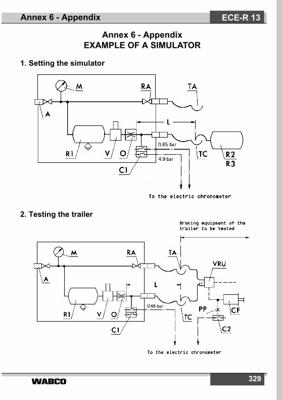
����� 329
Annex 6 - AppendixEXAMPLE OF A SIMULATOR
1. Setting the simulator
2. Testing the trailer
Annex 6 - Appendix ECE-R 13

�����330
3. Example of a simulator for electric control lines
A = supply connection with shut-off valveC1 = pressure switch in the simulator, set at 0.65 bar and at 4.9 barC2 = pressure switch to be connected to the brake actuator of the trailer, to
operate at 75 per cent of the asymptotic pressure in the brake actuator CFCF = brake cylinderECL = electric control line corresponding to ISO 7638L = line from orifice O up to and including its coupling head TC, having an
inner volume of 385 ± 5 cm3 under a pressure of 6.5 barM = pressure gaugeO = orifice with a diameter of not less than 4 mm and not more than 4.3 mmPP = pressure test connectionR1 = 30 - litre air reservoir with drain valveR2 = calibrating reservoir, including its coupling head TC, to be 385 ± 5 cm3
R3 = calibrating reservoir, including its coupling head TC, to be 1155 ± 15 cm3
RA = shut-off valveSIMU = simulator of Byte 3,4 of EBS 11 according to ISO 11992 with output
signals at start, 0.65 bar and 6.5 bar.TA = coupling head, supply lineTC = coupling head, control lineV = braking system control deviceVRU = emergency relay valve
Annex 6 - AppendixECE-R 13

����� 331
Annex 7
PROVISIONS RELATING TO ENERGY SOURCES AND ENERGY STORAGE DEVICES (ENERGY ACCUMULATORS)
A. COMPRESSED-AIR BRAKING SYSTEMS
1. CAPACITY OF ENERGY STORAGE DEVICES (ENERGY ACCUMULATORS)
1.1. General1.1.1. Vehicles on which the operation of the braking system requires the
use of compressed air shall be equipped with energy storage devices(energy accumulators) of a capacity meeting the requirements ofparagraphs 1.2. and 1.3. of this annex (Part A).
1.1.2. It must be possible to easily identify the reservoirs of the differentcircuits.
1.1.3. However, the energy storage devices shall not be required to be of aprescribed capacity if the braking system is such that in the absenceof any energy reserve it is possible to achieve a braking performanceat least equal to that prescribed for the secondary braking system.
1.1.4. In verifying compliance with the requirements of paragraphs 1.2. and1.3. of this annex (Part A), the brakes shall be adjusted as closely aspossible.
1.2. Power-Driven Vehicles1.2.1. The energy storage devices (energy accumulators) of power-driven
vehicles shall be such that after eight full-stroke actuations of theservice braking system control the pressure remaining in the energystorage device(s) shall be not less than the pressure required toobtain the specified secondary braking performance.
1.2.2. Testing shall be performed in conformity with the followingrequirements:
1.2.2.1. The initial energy level in the energy storage device(s) shall be thatspecified by the manufacturer.1) It shall be such as to enable theprescribed performance of the service braking system to beachieved.
Annex 7 ECE-R 13
1) The initial energy level shall be stated in the approval document.

�����332
1.2.2.2. The energy storage device(s) shall not be fed; in addition, any energystorage device(s) for auxiliary equipment shall be isolated.
1.2.2.3. In the case of power-driven vehicle to which the coupling of a trailer isauthorized and which is equipped with a pneumatic control line, thesupply line shall be stopped and a compressed-air reservoir of 0.5litre capacity shall be connected directly to the coupling head of thepneumatic control line. Before each braking operation, the pressurein this compressed-air reservoir shall be completely eliminated. Afterthe test referred to in paragraph 1.2.1. above, the energy levelsupplied to the pneumatic control line shall not fall below a levelequivalent to one-half the figure obtained at the first brakeapplication.
1.3. Trailers1.3.1. The energy storage devices (energy accumulators) with which
trailers are equipped shall be such that, after eight full-strokeactuations of the towing vehicle's service braking system, the energylevel supplied to the operating members using the energy does notfall below a level equivalent to one-half of the figure obtained at thefirst brake application and without actuating either the automatic orthe parking braking system of the trailer.
1.3.2. Testing shall be performed in conformity with the followingrequirements:
1.3.2.1. The pressure in the energy storage devices at the beginning of eachtest shall be 8.5 bar.
1.3.2.2. The supply line shall be stopped; in addition, any energy storagedevice(s) for auxiliary equipment shall be isolated.
1.3.2.3. The energy storage devices shall not be replenished during the test.1.3.2.4. At each brake application, the pressure in the pneumatic control line
shall be 7.5 bar.1.3.2.5. At each brake application, the digital demand value in the electric
control line shall be corresponding to a pressure of 7.5 bar.
2. CAPACITY OF ENERGY SOURCES2.1. General
The compressors shall meet the requirements set forth in thefollowing paragraphs.
2.2. Definitions2.2.1. ”p1“ is the pressure corresponding to 65 per cent of the pressure p2
defined in paragraph 2.2.2. below.
Annex 7ECE-R 13

����� 333
2.2.2. ”p2“ is the value specified by the manufacturer and referred to inparagraph 1.2.2.1. above.
2.2.3. ”t1“ is the time required for the relative pressure to rise from 0 to p1,and ”t2“ is the time required for the relative pressure to rise from 0 top2.
2.3. Conditions of Measurement2.3.1. In all cases, the speed of the compressor shall be that obtained when
the engine is running at the speed corresponding to its maximumpower or at the speed allowed by the governor.
2.3.2. During the tests to determine the time t1 and the time t2, the energystorage device(s) for auxiliary equipment shall be isolated.
2.3.3. If it is intended to attach a trailer to a power-driven vehicle, the trailershall be represented by an energy storage device whose maximumrelative pressure p (expressed in bar) is that which can be suppliedthrough the towing vehicle's supply circuit and whose volume V,expressed in litres, is given by the formula p • V = 20 R (R being thepermissible maximum mass, in tons, on the axles of the trailer).
2.4. Interpretation of Results2.4.1. The time t1 recorded for the least-favoured energy storage device
shall not exceed:2.4.1.1. Three minutes in the case of vehicles to which the coupling of a trailer
is not authorized or2.4.1.2. Six minutes in the case of vehicles to which the coupling of a trailer is
authorized.2.4.2. The time t2 recorded for the least-favoured energy storage device
shall not exceed:2.4.2.1. Six minutes in the case of vehicles to which the coupling of a trailer is
not authorized or2.4.2.2. Nine minutes in the case of vehicles to which the coupling of a trailer
is authorized.
2.5. Additional Test2.5.1. If the power-driven vehicle is equipped with one or more energy
storage devices for auxiliary equipment having a total capacityexceeding 20 per cent of the total capacity of the braking energystorage devices, an additional test shall be performed during whichno irregularity shall occur in the operation of the valves controlling thefilling of the energy storage device(s) for auxiliary equipment.
Annex 7 ECE-R 13

�����334
2.5.2. It shall be verified during the aforesaid test that the time t3 necessaryto raise the pressure from 0 to p2 in the least-favoured brakingenergy storage device is less than:
2.5.2.1. Eight minutes in the case of vehicles to which the coupling of a traileris not authorized or
2.5.2.2. Eleven minutes in the case of vehicles to which the coupling of atrailer is authorized.
2.5.3. The test shall be performed on the conditions prescribed inparagraphs 2.3.1. and 2.3.3. above.
2.6. Towing vehicles2.6.1. Power-driven vehicles, to which the coupling of a category O3/O4
vehicle is authorized shall also comply with the above requirementsfor vehicles not so authorized. In that case, the tests in paragraph2.4.1. and 2.4.2. (and 2.5.2.) of this annex will be conducted withoutthe energy storage device mentioned in paragraph 2.3.3. above.
B. VACUUM BRAKING SYSTEMS
1. CAPACITY OF ENERGY STORAGE DEVICES (ENERGY ACCUMULATORS)
1.1. General1.1.1. Vehicles on which operation of the braking system requires the use
of a vacuum shall be equipped with energy storage devices (energyaccumulators) of a capacity meeting the requirements of paragraphs1.2. and 1.3. of this annex (Part B).
1.1.2. However, the energy storage devices shall not be required to be of aprescribed capacity if the braking system is such that in the absenceof any energy reserve it is possible to achieve a braking performanceat least equal to that prescribed for the secondary braking system.
1.1.3. In verifying compliance with the requirements of paragraphs 1.2. and1.3. of this annex (Part B), the brakes shall be adjusted as closely aspossible.
1.2. Power-Driven Vehicles1.2.1. The energy storage devices (energy accumulators) of power-driven
vehicles shall be such that it is still possible to achieve theperformance prescribed for the secondary braking system:
1.2.1.1. after eight full-stroke actuations of the service braking system controlwhere the energy source is a vacuum pump and
Annex 7ECE-R 13

����� 335
1.2.1.2. after four full-stroke actuations of the service brake control where theenergy source is the engine.
1.2.2. Testing shall be performed in conformity with the followingrequirements:
1.2.2.1. the initial energy level in the energy storage device(s) shall be thatspecified by the manufacturer.1) It shall be such as to enable theprescribed performance of the service braking sytem to be achievedand shall correspond to a vacuum not exceeding 90 per cent of themaximum vacuum furnished by the energy source.
1.2.2.2. The energy storage device(s) shall not be fed; in addition any energystorage device(s) for auxiliary equipment shall be isolated.
1.2.2.3. In the case of a power-driven vehicle authorized to tow a trailer, thesupply line shall be stopped and an energy storage device of 0.5 litrecapacity shall be connected to the control line. After the test referredto in paragraph 1.2.1. above, the vacuum level provided at the controlline shall not have fallen below a level equivalent to one-half of thefigure obtained at the first brake application.
1.3. Trailers (categories O1 and O2 only)1.3.1. The energy storage devices (energy accumulators) with which
trailers are equipped shall be such that the vacuum level provided atthe user points shall not have fallen below a level equivalent to one-half of the value obtained at the first brake application after a testcomprising four full-stroke actuations of the trailer's service brakingsystem.
1.3.2. Testing shall be performed in conformity with the followingrequirements:
1.3.2.1. The initial energy level in the energy storage device(s) shall be thatspecified by the manufacturer. 1) It shall be such as to enable theprescribed performance of the service braking system to beachieved.
1.3.2.2. The energy storage device(s) shall not be fed; in addition, any energystorage device(s) for auxiliary equipment shall be isolated.
2. CAPACITY OF ENERGY SOURCES2.1. General2.1.1. Starting from the ambient atmospheric pressure, the energy source
shall be capable of achieving in the energy storage device(s), in 3
Annex 7 ECE-R 13
1) The initial energy level shall be stated in the approval document.

�����336
minutes, the initial level specified in paragraph 1.2.2.1. above. In thecase of a power-driven vehicle to which the coupling of a trailer isauthorized, the time taken to achieve that level on the conditionsspecified in paragraph 2.2. below shall not exceed 6 minutes.
2.2. Conditions of Measurement2.2.1. The speed of the vacuum source shall be:2.2.1.1. Where the vacuum source is the vehicle engine, the engine speed
obtained with the vehicle stationary, the neutral gear engaged andthe engine idling;
2.2.1.2. Where the vacuum source is a pump, the speed obtained with theengine running at 65 per cent of the speed corresponding to itsmaximum power output and
2.2.1.3. Where the vacuum source is a pump and the engine is equipped witha governor, the speed obtained with the engine running at 65 percent of the maximum speed allowed by the governor.
2.2.2. Where it is intended to couple to the power-driven vehicle a trailerwhose service braking system is vacuum-operated, the trailer shallbe represented by an energy storage device having a capacity V inlitres determined by the formula V = 15 R, where R is the maximumpermissible mass, in tons, on the axles of the trailer.
C. HYDRAULIC BRAKING SYSTEMS WITH STOREDENERGY
1. CAPACITY OF ENERGY STORAGE DEVICES (ENERGY ACCUMULATORS).
1.1. General1.1.1. Vehicles on which operation of the braking system requires the use
of stored energy provided by hydraulic fluid under pressure shall beequipped with energy storage devices (energy accumulators) of acapacity meeting the requirements of paragraph 1.2. of this annex(Part C).
1.1.2. However, the energy storage devices shall not be required to be of aprescribed capacity if the braking system is such that in the absenceof any energy reserve it is possible with the service braking systemcontrol to achieve a braking performance at least equal to thatprescribed for the secondary braking system.
Annex 7ECE-R 13

����� 337
1.1.3. In verifying compliance with the requirements of paragraphs 1.2.1.,1.2.2. and 2.1. of this annex, the brakes shall be adjusted as closelyas possible and, for paragraph 1.2.1., the rate of full-strokeactuations must be such as to provide an interval of at least 60seconds between each actuation.
1.2. Power-Driven Vehicles1.2.1. Power-driven vehicles equipped with a hydraulic braking system with
stored energy shall meet the following requirements:1.2.1.1. After eight full-stroke actuations of the service braking system
control, it shall still be possible to achieve, on the ninth application,the performance prescribed for the secondary braking system.
1.2.1.2. Testing shall be performed in conformity with the followingrequirements:
1.2.1.2.1. Testing shall commence at a pressure that may be specified by themanufacturer but is not higher than the cut-in pressure.
1.2.1.2.2. The energy storage device(s) shall not be fed; in addition, any energystorage device(s) for auxiliary equipment shall be isolated.
1.2.2. Power-driven vehicles equipped with a hydraulic braking system withstored energy which cannot meet the requirements of paragraph5.2.1.5.1. of this Regulation shall be deemed to satisfy thatparagraph if the following requirements are met:
1.2.2.1. After any single transmission failure it shall still be possible after eightfull-stroke actuations of the service braking system control, toachieve, at the ninth application, at least the performance prescribedfor the secondary braking system or, where secondary performancerequiring the use of stored energy is achieved by a separate control,it shall still be possible after eight full-stroke actuations to achieve, atthe ninth application, the residual performance prescribed inparagraph 5.2.1.4. of this Regulation.
1.2.2.2. Testing shall be performed in conformity with the followingrequirements:
1.2.2.2.1. With the energy source stationary or operating at a speedcorresponding to the engine idling speed, any transmission failuremay be induced. Before inducing such a failure, the energy storagedevice(s) shall be at a pressure that may be specified by themanufacturer but not exceeding the cut-in pressure.
1.2.2.2.2. The auxiliary equipment and its energy storage devices, if any, shallbe isolated.
Annex 7 ECE-R 13

�����338
2. CAPACITY OF HYDRAULlC FLUID ENERGY SOURCES2.1. The energy sources shall meet the requirements set out in the
following paragraphs:2.1.1. Definitions2.1.1.1. ”p1“ represents the maximum system operational pressure (cut-out
pressure) in the energy storage device(s) specified by themanufacturer.
2.1.1.2. ”p2“ represents the pressure after four full-stroke actuations with theservice brake control, starting at p1, without having fed the energystorage device(s).
2.1.1.3. ”t“ represents the time required for the pressure to rise from p2 to p1in the energy storage device(s) without application of the servicebraking system control.
2.1.2. Conditions of Measurement2.1.2.1. During the test to determine the time t, the feed rate of the energy
source shall be that obtained when the engine is running at thespeed corresponding to its maximum power or at the speed allowedby the over-speed governor.
2.1.2.2. During the test to determine the time t, energy storage device(s) forauxiliary equipment shall not be isolated other than automatically.
2.1.3. Interpretation of Results2.1.3.1. In the case of all vehicles except those of categories M3, N2 and N3,
the time t shall not exceed 20 seconds.2.1.3.2. In the case of vehicles of categories M3, N2 and N3, the time t shall
not exceed 30 seconds.
3. CHARACTERISTICS OF WARNING DEVICESWith the engine stationary and commencing at a pressure that maybe specified by the manufacturer but does not exceed the cut-inpressure, the warning device shall not operate following two full-stroke actuations of the service braking system control.
Annex 7ECE-R 13

����� 339
Annex 8
PROVISIONS RELATING TO SPECIFIC CONDITIONS FOR SPRING BRAKING SYSTEMS
1. DEFINITION1.1. ”Spring braking systems“ are braking systems in which the energy
required for braking is supplied by one or more springs acting as anenergy storage device (energy accumulator).
1.1.1. The energy necessary to compress the spring in order to release thebrake is supplied and controlled by the ”control“ actuated by thedriver (see definition in paragraph 2.4. of this Regulation).
1.2. ”Spring compression chamber“ means the chamber where thepressure variation that induces the compression of the spring isactually produced.
1.3. If the compression of the springs is obtained by means of a vacuumdevice, ”pressure“ shall mean negative pressure everywhere in thisannex.
2. GENERAL2.1. A spring braking system shall not be used as a service braking
system. However, in the event of a failure in a part of the transmissionof the service braking system, a spring braking system may be usedto achieve the residual performance prescribed in paragraph 5.2.1.4.of this Regulation provided that the driver can graduate this action. Inthe case of power-driven vehicles, with the exception of tractors forsemi-trailers meeting the requirements specified in paragraph5.2.1.4.1. of this Regulation, the spring braking system shall not bethe sole source of residual braking. Vacuum spring braking systemsshall not be used for trailers.
2.2. A small variation in any of the pressure limits which may occur in thespring compression chamber feed circuit shall not cause a significantvariation in the braking force.
2.3. The following requirements shall apply to power-driven vehiclesequipped with spring brakes:
2.3.1. The feed circuit to the spring compression chamber must eitherinclude an own energy reserve or must be fed from at least twoindependent energy reserves. The trailer supply line may be
Annex 8 ECE-R 13
�����340
branched from this feed line under the condition that a pressure dropin the trailer supply line must not be able to apply the spring brakeactuators.
2.3.2. Auxiliary equipment may only draw its energy from the feed line forthe spring brake actuators under the condition that its operation,even in the event of damage to the energy source, cannot cause theenergy reserve for the spring brake actuators to fall below a levelfrom which one release of the spring brake actuators is possible.
2.3.3. In any case, during re-charging of the braking system from zeropressure, the spring brakes shall remain fully applied irrespective ofthe position of the control device until the pressure in the servicebraking system is sufficient to ensure at least the prescribedsecondary braking performance of the laden vehicle, using theservice braking system control.
2.3.4. Once applied, the spring brakes must not release unless there issufficient pressure in the service braking system to at least providethe prescribed residual braking performance of the laden vehicle byapplication of the service braking control.
2.4. In power-driven vehicles, the system must be so designed that it ispossible to apply and release the brakes at least three times if theinitial pressure in the spring compression chamber is equal to themaximum design pressure. In the case of trailers, it must be possibleto release the brakes at least three times after the trailer has beenuncoupled, the pressure in the supply line being 7.5 bar before theuncoupling. However, prior to the check the emergency brake shallbe released. These conditions must be satisfied when the brakes areadjusted as closely as possible. In addition, it must be possible toapply and release the parking braking system as specified inparagraph 5.2.2.10. of this Regulation when the trailer is coupled tothe towing vehicle.
2.5. For power-driven vehicles, the pressure in the spring compressionchamber beyond which the springs begin to actuate the brakes, thelatter being adjusted as closely as possible, shall not be greater than80 per cent of the minimum level of the normal available pressure.
In the case of trailers, the pressure in the spring compression cham-ber beyond which the springs begin to actuate the brakes must notbe greater than that obtained after four full-stroke actuations of theservice braking system in accordance with paragraph 1.3. of Part Aof annex 7 to this Regulation. The initial pressure fixed at read 7.0bar.
Annex 8ECE-R 13

����� 341
2.6. When the pressure in the line feeding energy to the springcompression chamber - excluding lines of an auxiliary release deviceusing a fluid under pressure - falls to the level at which the brakeparts begin to move, an optical or audible warning device shall beactuated. Provided this requirement is met, the warning device maycomprise the red warning signal specified in paragraph 5.2.1.29.1.1.of this Regulation. This provision does not apply to trailers.
2.7. If a power-driven vehicle authorized to tow a trailer with a continuousor semi-continuous braking is fitted with a spring braking system,automatic application of the said system shall cause application ofthe trailer's brakes.
3. AUXILIARY RELEASE SYSTEM3.1. A spring braking system must be so designed that, in the event of a
failure in that system, it is still possible to release the brakes. Thismay be achieved by the use of an auxiliary release device(pneumatic, mechanical, etc.).
Auxiliary release devices using an energy reserve for releasing mustdraw their energy from an energy reserve which is independent of theenergy reserve normally used for the spring braking system. Thepneumatic or hydraulic fluid in such an auxiliary release device mayact on the same piston surface in the spring compression chamberwhich is used for the normal spring braking system under the condi-tion that the auxiliary release device uses a separate line. Thejunction of this line with the normal line connecting the control devicewith the spring brake actuators shall be at each spring brake actuatorimmediately before the port to the spring compression chamber, if notintegrated in the body of the actuator. This junction shall include adevice which prevents an influence of one line on the other. Therequirements of paragraph 5.2.1.6. of this Regulation also apply tothis device.
3.1.1. For the purposes of the requirement of paragraph 3.1. above,components of the braking system transmission shall not beregarded as subject to failure if under the terms of paragraph5.2.1.2.7. of this Regulation they are not regarded as liable tobreakage, provided that they are made of metal or of a materialhaving similar characteristics and do not undergo significantdistortion in normal braking.
3.2. If the operation of the auxiliary device referred to in paragraph 3.1.above requires the use of a tool or spanner, the tool or spanner shallbe kept on the vehicle.
Annex 8 ECE-R 13
�����342
3.3. Where an auxiliary release system utilizes stored energy to releasethe spring brakes the following additional requirements shall apply:
3.3.1. Where the control of the auxiliary spring brake release system is thesame as that used for the secondary/parking brake, the requirementsdefined in paragraph 2.3. above shall apply in all cases.
3.3.2. Where the control for the auxiliary spring brake release system isseparate to the secondary/parking brake control, the requirementsdefined in paragraph 2.3. above shall apply to both control systems.However, the requirements of paragraph 2.3.4. above shall not applyto the auxiliary spring brake release system. in addition the auxiliaryrelease control shall be located so that it is protected againstapplication by the driver from the normal driving position.
3.4. If compressed air is used in the auxiliary release system, the systemshould be activated by a separate control, not connected to thespring brake control.
Annex 8ECE-R 13

����� 343
Annex 9
PROVISIONS RELATING TO PARKING BRAKING SYSTEMS EQUIPPED WITH A MECHANICAL BRAKE CYLINDER
LOCKING DEVICE (Lock actuators)
1. DEFINITION”Mechanical brake cylinder locking device“ means a device whichensures braking operation of the parking braking system by mechani-cally locking the brake piston rod. Mechanical locking is effected byexhausting the compressed fluid held in the locking chamber; it is sodesigned that unlocking can be effected by restoring pressure in thelocking chamber.
2. SPECIAL REQUIREMENTS2.1. When the pressure in the locking chamber approaches the level at
which mechanical locking occurs, an optical or audible warningdevice shall come into action. Provided this requirement is met, thewarning device may comprise the red warning signal specified inparagraph 5.2.1.29.1.1. of this Regulation. This provision shall notapply to trailers. In the case of trailers, the pressure corresponding tomechanical locking must not exceed 4 bar. It must be possible toachieve parking braking performance after any single failure of thetrailer service braking system. In addition, it must be possible torelease the brakes at least three times after the trailer has beenuncoupled, the pressure in the supply line being 6.5 bar before theuncoupling. These conditions must be satisfied when the brakes areadjusted as closely as possible. It must also be possible to apply andrelease the parking braking system as specified in paragraph5.2.2.10. of this Regulation when the trailer is coupled to the towingvehicle.
2.2. In cylinders equipped with a mechanical locking device, movement ofthe brake piston shall be ensured by energy from either of twoindependent energy storage devices.
Annex 9 ECE-R 13

�����344
2.3. It shall not be possible to release the locked brake cylinder unless itis certain that after such release the brake can be applied again.
2.4. In the event of a failure of the energy source feeding the lockingchamber, an auxiliary release device (e.g. mechanical, or pneumaticwhich may use the air contained in one of the vehicle's tyres) shall beavailable.
2.5. The control must be such that, when actuated, it performs thefollowing operations in sequence: it applies the brakes so as toprovide the degree of efficiency required for parking braking, locksthe brakes in that position and then cancels out the brake applicationforce.
2.6 When the pressure in the locking chamber approaches the level atwhich mechanical locking occurs, an optical or audible warningdevice shall come into action. Provided this requirement is met, thewarning device may comprise the red warning signal specified inparagraph 5.2.1.29.1.1. of this Regulation. This provision shall notapply to trailers.
Annex 9ECE-R 13

����� 345
Annex 10DISTRIBUTION OF BRAKING AMONG THE AXLES OF
VEHICLES AND REQUIREMENTS FOR COMPATIBILITY BETWEEN TOWING VEHICLES AND TRAILERS
1. GENERAL REQUIREMENTS1.1. Vehicles of categories M, N, O2, O3 and O4 which are not equipped
with an anti-lock braking system as defined in annex 13 to thisRegulation shall meet all the requirements of this annex. If a specialdevice is used, this must operate automatically. *)However, vehicles – other than those of category M1 – which areequipped with an anti-lock braking system as defined in annex 13,shall also meet the requirements of paragraphs 7 and 8 of this annexif they are in addition fitted with a special automatic device whichcontrols the distribution of braking among the axles. In the event offailure of its control, it shall be possible to stop the vehicle asstipulated under Paragraph 6 of this annex.
1.1.1. Where a vehicle is installed with an endurance braking system theretarding force produced by that system shall not be taken intoconsideration when determining the vehicle performance with respectto the provisions of this annex.
1.2. The requirements relating to the diagrams specified in paragraphs3.1.5., 3.1.6., 4.1., 5.1. and 5.2. of this annex, are valid both forvehicles with a pneumatic control line according to paragraph5.1.3.1.1. of this Regulation and for vehicles with an electric controlline according to paragraph 5.1.3.1.3. of this Regulation. In bothcases, the reference value (abscissa of the diagrams) will be thevalue of the transmitted pressure in the control line: for vehiclesequipped according to paragraph 5.1.3.1.1. of this Regulation, thiswill be the actual pneumatic pressure in the control line (pm); forvehicles equipped according to paragraph 5.1.3.1.3. of thisRegulation, this will be the pressure corresponding to the transmitteddigital demand value in the electric control line, according to ISO11992: 2003. Vehicles equipped according to paragraph 5.1.3.1.2. ofthis Regulation (with both pneumatic and electric control lines) shall
ECE-R 13Annex 10
*) In the case of trailers with electronically controlled brake force distributionthe requirements of this annex shall only apply when the trailer is electricallyconnected to a towing vehicle by the ISO 7638: 1997 connector.

�����346
satisfy the requirements of the diagrams related to both control lines.However, identical braking characteristic curves related to bothcontrol lines are not required.
1.3. Validation of the development of braking force. 1.3.1. At the time of type approval it shall be checked that the development
of braking on an axle of each independent axle group *) shall bewithin the following pressure ranges: (a) Laden vehicles:
At least one axle shall commence to develop a braking forcewhen the pressure at the coupling head is within the pressurerange 0.2 to 1.0 bar. At least one axle of any other axle group shall commence todevelop a braking force when the pressure at the coupling headis at a pressure � 1.2 bar.
(b) Unladen vehicles: At least one axle shall commence to develop a braking forcewhen the pressure at the coupling head is within the pressurerange 0.2 to 1.0 bar.
1.3.1.1. With the wheel(s) of the axle(s) raised off the ground and free torotate, apply an increasing brake demand and measure the couplinghead pressure corresponding to when the wheel(s) can no longer berotated by hand. This condition is defined as the development of thebraking force.
1.4. In the case of vehicles of category O with pneumatic brakingsystems, when the alternative type approval procedure defined inannex 20 is utilised, the relevant calculations required in this annexshall be made using the performance characteristics obtained fromthe relevant annex 19 verification reports and the centre of gravityheight determined by the method defined in annex 20, appendix 1.
2. SYMBOLSi = axle index (i = 1, front axle; i = 2, second axle; etc.)Pi = normal reaction of road surface on axle i under static con-
ditions
ECE-R 13 Annex 10
*) An axle group is where a number of axles have a maximum axle spread of2 m.
1) ”Adhesion utilization curves“ of a vehicle means curves showing, for speci-fied load conditions, the adhesion utilized by each axle i plotted against thebraking rate of the vehicle.
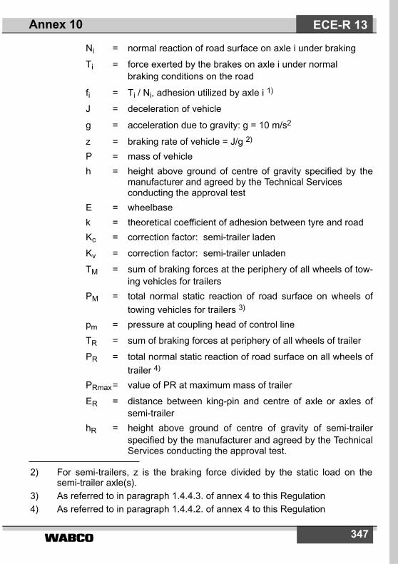
����� 347
Ni = normal reaction of road surface on axle i under braking
Ti = force exerted by the brakes on axle i under normal braking conditions on the road
fi = Ti / Ni, adhesion utilized by axle i 1)
J = deceleration of vehicle
g = acceleration due to gravity: g = 10 m/s2
z = braking rate of vehicle = J/g 2)
P = mass of vehicleh = height above ground of centre of gravity specified by the
manufacturer and agreed by the Technical Services conducting the approval test
E = wheelbasek = theoretical coefficient of adhesion between tyre and roadKc = correction factor: semi-trailer laden
Kv = correction factor: semi-trailer unladen
TM = sum of braking forces at the periphery of all wheels of tow-ing vehicles for trailers
PM = total normal static reaction of road surface on wheels oftowing vehicles for trailers 3)
pm = pressure at coupling head of control line
TR = sum of braking forces at periphery of all wheels of trailer
PR = total normal static reaction of road surface on all wheels oftrailer 4)
PRmax= value of PR at maximum mass of trailer
ER = distance between king-pin and centre of axle or axles ofsemi-trailer
hR = height above ground of centre of gravity of semi-trailerspecified by the manufacturer and agreed by the TechnicalServices conducting the approval test.
ECE-R 13Annex 10
2) For semi-trailers, z is the braking force divided by the static load on thesemi-trailer axle(s).
3) As referred to in paragraph 1.4.4.3. of annex 4 to this Regulation4) As referred to in paragraph 1.4.4.2. of annex 4 to this Regulation

�����348
3. REQUIREMENTS FOR POWER-DRIVEN VEHICLES
3.1. Two-axled vehicles3.1.1. For all categories of vehicles for k values between 0.2 and 0.8: 5)
z � 0.1 + 0.85 (k - 0.2)3.1.2. For all states of load of the vehicle, the adhesion utilization curve of
the rear axle shall not be situated above that for the front axle:3.1.2.1. for all braking rates between 0.15 and 0.80 in the case of vehicles of
category M1.
However, for vehicles of this category in the range of z values between0.30 and 0.45, an inversion of the adhesion utilization curves is permit-ted provided that the adhesion utilization curve of the rear axle doesnot exceed by more than 0.05 the line defined by the formula k = z (lineof ideal adhesion utilization – see diagram 1A of this annex);
3.1.2.2. for all braking rates between 0.15 and 0.50 in the case of vehicles ofcategory N1. 6)
This condition is also considered satisfied if, for braking rates bet-ween 0.15 and 0.30, the adhesion utilization curves for each axle aresituated between two lines parallel to the line of ideal adhesion utili-zation given by the equations k = z ± 0.08 as shown in diagram 1C ofthis annex where the adhesion utilization curve for the rear axle maycross the line k = z - 0.08; and complies for a braking rate between0.30 and 0.50, with the relation z � k - 0.08; and between 0.50 and0.61 with the relation z � 0.5k + 0.21.
3.1.2.3. For all braking rates between 0.15 and 0.30 in the case of vehicles ofother categories; this condition is also considered satisfied if, forbraking rates between 0.15 and 0.30, the adhesion utilization curves
ECE-R 13 Annex 10
5) The provisions of paragraph 3.1.1. or 5.1.1. do not affect the requirements ofannex 4 to this Regulation relating to the braking performance. However, if,in tests made under the provisions of paragraph 3.1.1. or 5.1.1., braking per-formances are obtained which are higher than those prescribed in annex 4,the provisions relating to the adhesion utilization curves shall be appliedwithin the areas of diagrams 1A, 1B and 1C of this annex defined by thestraight lines k = 0.8 and z = 0.8.
6) Vehicles of category N1 with a laden/unladen rear axle loading ratio notexceeding 1.5 or having a maximum mass of less than 2 tonnes will have tocomply with the requirements for category M1 vehicles laid down in para-graph 3.1.2.1. of this annex as from 1 October 1990.

����� 349
for each axle are situated between two lines parallel to the line ofideal adhesion utilization given by the equations k = z ± 0.08 asshown in diagram 1B of this annex and the adhesion utilization curvefor the rear axle for braking rates z � 0.3 complies with the relationz � 0.3 + 0.74 (k - 0.38).
3.1.3. In the case of a power-driven vehicle authorized to tow trailers ofcategory O3 or O4 fitted with compressed-air braking systems.
3.1.3.1. When tested with the energy source stopped, the supply line blockedoff, a reservoir of 0.5 litre capacity connected to the pneumatic controlline, and the system at cut-in and cut-out pressures, the pressure atfull application of the braking control shall be between 6.5 and 8.5 barat the coupling heads of the supply line and the pneumatic controlline, irrespective of the load condition of the vehicle.
3.1.3.2. For vehicles equipped with an electric control line; a full application ofthe control of the service braking system shall provide a digitaldemand value corresponding to a pressure between 6.5 and 8.5 bar(see ISO 11992: 2003 ).
3.1.3.3. These values shall be demonstrably present in the power-drivenvehicle when uncoupled from the trailer. The compatibility bands inthe diagrams specified in paragraphs 3.1.5., 3.1.6., 4.1., 5.1. and 5.2.of this annex, should not be extended beyond 7.5 bar and/or thecorresponding digital demand value (see ISO 11992: 2003).
3.1.3.4. It must be ensured that at the coupling head of the supply line apressure of at least 7 bar is available when the system is at cut-inpressure. This pressure shall be demonstrated without applying theservice brakes.
3.1.4. Verification of the requirements of paragraphs 3.1.1. and 3.1.2.3.1.4.1. In order to verify the requirements of paragraphs 3.1.1. and 3.1.2. of
this annex, the manufacturer shall provide the adhesion utilizationcurves for the front and rear axles calculated by the formulae:
f1 = =
f2 = =
The curves shall be plotted for both the following load conditions:
T1N1-------
T1
P1 z hE---- P g� � �+
-----------------------------------------
T2N2-------
T2
P2 z hE---- P g� � �+
-----------------------------------------
ECE-R 13Annex 10

�����350
3.1.4.1. 1. unladen, in running order with the driver on board; in the case of avehicle presented as a bare chassis-cab, a supplementary load maybe added to simulate the mass of the body, not exceeding theminimum mass declared by the manufacturer in annex 2 to thisRegulation,
3.1.4.1.2. laden; where provision is made for several possibilities of loaddistribution, the one whereby the front axle is the most heavily ladenshall be the one considered.
3.1.4.2. If it is not possible, for vehicles with (permanent) all-wheel drive, tocarry out the mathematical verification pursuant to paragraph3.1.4.1., the manufacturer may instead verify by means of a wheellock sequence test that, for all braking rates between 0.15 and 0.8,lockup of the front wheels occurs either simultaneously with or beforethe lockup of the rear wheels.
3.1.4.3. Procedure to verify the requirements of paragraph 3.1.4.2.3.1.4.3.1. The wheel lock sequence test shall be conducted on road surfaces
with a coefficient of adhesion of not more than 0.3 and of about 0.8(dry road) from the initial test speeds specified in paragraph3.1.4.3.2.
3.1.4.3.2. Test speeds:
60 km/h, but not exceeding 0.8 vmax for decelerations on low coef-ficient of friction road surfaces;
80 km/h, but not exceeding vmax for decelerations on high coefficientof friction road surfaces.
3.1.4.3.3. The pedal force applied may exceed the permissible actuation forcespursuant to annex 4, paragraph 2.1.1.
3.1.4.3.4. Pedal force is applied and increased such that the second wheel onthe vehicle will reach lockup between 0.5 and 1 s after initiating thebrake application, until lockup of both wheels on one axle occurs(additional wheels may also lock during the test, e.g. in the case ofsimultaneous lockup).
3.1.4.4. The tests prescribed in paragraph 3.1.4.2. shall be carried out twiceon each road surface, If the result of one test fails, a third, hencedecisive test shall be carried out.
3.1.4.5. For vehicles fitted with an electric regenerative braking system ofcategory B, where the electric regenerative braking capacity isinfluenced by the electric state of charge, the curves shall be plottedby taking account of the electric regenerative braking componentunder the minimum and maximum conditions of delivered braking
ECE-R 13 Annex 10

����� 351
force. This requirement is not applicable if the vehicle is equippedwith an antilock device which controls the wheels connected to theelectric regenerative braking and shall be replaced by therequirements of annex 13.
3.1.5. Towing vehicles other than tractors for semi-trailers3.1.5.1. In the case of a power-driven vehicle authorized to tow trailers of
category O3 or O4 fitted with a compressed air braking system, thepermissible relationship between the braking rate TM/PM and thepressure pm shall lie within the areas shown on diagram 2 of thisannex for all pressures between 0.2 and 7.5 bar.
3.1.6. Tractors for semi-trailers3.1.6.1. Tractors with unladen semi-trailer. An unladen combination is
understood to be a tractor in running order, with the driver on board,coupled to an unladen semi-trailer. The dynamic load of the semi-trailer on the tractor shall be represented by a static mass Psmounted at the fifth wheel coupling equal to 15 per cent of themaximum mass on the coupling. The braking forces must continue tobe regulated between the state of the ”tractor with unladen semi-trailer“ and that of the ”tractor alone“; the braking forces relating tothe ”tractor alone“ shall be verified.
3.1.6.2. Tractors with laden semi-trailer. A laden combination is understood tobe a tractor in running order, with the driver on board, coupled to aladen semi-trailer. The dynamic load of the semi-trailer on the tractorshall be represented by a static mass Ps mounted at the fifth wheelcoupling equal to:
Ps = Pso (1 + 0.45 z)
where:Pso represents the difference between the maximum laden
mass of the tractor and its unladen mass.For h the following value shall be taken:
h =
where:ho is the height of the centre of gravity of the tractorhs is the height of the coupling on which the semi-trailer restsPo is the unladen mass of the tractor alone
ho Po hs P� s+�
P------------------------------------------
ECE-R 13Annex 10
�����352
P = Po + Ps =
3.1.6.3. In the case of a vehicle fitted with a compressed air braking system,the permissible relationship between the braking rate TM/PM and thepressure pm shall be within the areas shown on diagram 3 of thisannex for all pressures between 0.2 and 7.5 bar.
3.2. Vehicles with more than two axles.The requirements of paragraph 3.1. of this annex shall apply to vehic-les with more than two axles. The requirements of paragraph 3.1.2.of this annex with respect to wheel lock sequence shall be conside-red to be met if, in the case of braking rates between 0.15 and 0.30,the adhesion utilized by at least one of the front axles is greater thanthat utilized by at least one of the rear axles.
4. REQUIREMENTS FOR SEMI-TRAILERS
4.1. For semi-trailers fitted with compressed air braking systems4.1.1. The permissible relationship between the braking rate TR/PR and the
pressure pm shall lie within two areas derived from diagrams 4A and4B for all pressures between 0.2 and 7.5 bar, in both the laden andunladen states of load. This requirement shall be met for allpermissible load conditions of the semi-trailer axles.
4.1.2. If the requirements of paragraph 4.1.1. of this annex cannot besatisfied in conjunction with the requirements of paragraph 3.1.2.1. ofannex 4 to this Regulation for semi-trailers with a Kc factor less than0.80, then the semi-trailer must meet the minimum brakingperformance specified in paragraph 3.1.2.1. of annex 4 to thisRegulation and be fitted with an anti-lock braking system complyingwith annex 13 to this Regulation, except the compatibilityrequirement in paragraph 1 of that annex.
5. REQUIREMENTS FOR FULL AND CENTRE-AXLE TRAILERS
5.1. For full trailers fitted with compressed air braking systems5.1.1. For full trailers with two axles (except where the axle spread is less
than 2 metres) the following requirements apply:
P1 P2+g
--------------------
ECE-R 13 Annex 10

����� 353
5.1.1.1. For k values between 0.2 and 0.8: 5)
z � 0.1 + 0.85 (k - 0.2)5.1.1.2. For all states of load of the vehicle, the adhesion utilization curve of
the rear axle shall not be situated above that for front axle for allbraking rates between 0.15 and 0.30. This condition is also consideredsatisfied if, for braking rates between 0.15 and 0.30, the adhesionutilization curve for each are situated between two lines parallel to theline of ideal adhesion utilization given by the equations k = z + 0.08and k = z - 0.08 as shown in diagram 1B of this annex and theadhesion utilization curve for the rear axle for braking rates z � 0.3complies with the relation
z � 0.3 + 0.74 (k - 0.38).5.1.1.3. For the verification of the requirements of paragraphs 5.1.1.1. and
5.1.1.2. the procedure should be as that in the provisions ofparagraph 3.1.4.
5.1.2. For full trailers with more than two axles the requirements ofparagraph 5.1.1. of this annex shall apply. The requirements ofparagraph 5.1.1. of this annex with respect to wheel lock sequenceshall be considered to be met if, in the case of braking rates between0.15 and 0.30, the adhesion utilized by at least one of the front axlesis greater than that utilized by at least one of the rear axles.
5.1.3 The permissible relationship between the braking rate TR/PR and thepressure pm shall lie within the designated areas in diagram 2 of thisannex for all pressures between 0.2 and 7.5 bar, in both the ladenand unladen states of load.
5.2. For centre-axle trailers fitted with compressed air braking systems
5.2.1. The permissible relationship between the braking rate TR/PR and thepressure pm shall lie within two areas derived from diagram 2 of thisannex, by multiplying the vertical scale by 0.95. This requirementshall be met at all pressures between 0.2 and 7.5 bar, in both theladen and unladen states of load.
5.2.2. If the requirements of paragraph 3.1.2.1. of annex 4 to thisRegulation cannot be satisfied due to lack of adhesion, then thecentre-axle trailer must be fitted with an anti-lock braking systemcomplying with annex 13 to this Regulation.
ECE-R 13Annex 10
5) see page 348
�����354
5.3. For full trailers with inertia (overrun) braking system5.3.1. The requirements according to paragraph 5.1.1. apply also for full
trailers with inertia (overrun) braking system.5.3.2. For full trailers with inertia (overrun) braking system and with more
than two axles the requirements according to paragraph 5.1.2. apply.5.3.3. For the calculation to verify the compliance with the provisions of
paragraph 5.1.1.3. the influence of the permissible drawbar force D*(paragraph 9.3.1. annex 12) can be ignored.
6. REQUIREMENTS TO BE MET IN CASE OF FAILURE OF THE BRAKING DISTRIBUTION SYSTEMWhen the requirements of this annex are fulfilled by means of a spe-cial device (e.g. controlled mechanically by the suspension of thevehicle), it shall be possible, in the event of the failure of its control, tostop the vehicle under the conditions specified for secondary brakingin the case of power-driven vehicles; for those power-driven vehiclesauthorized to tow a trailer fitted with compressed air braking systems,it must be possible to achieve a pressure at the coupling head of thecontrol line within the range specified in paragraph 3.1.3. of thisannex. In the event of failure of the control of the device on trailers, aservice braking performance of at least 30 per cent of that prescribedfor the vehicle in question shall be attained.
7. MARKINGS7.1. Vehicles, other than those of category M1, which meet the
requirements of this annex by means of a device mechanicallycontrolled by the suspension of the vehicle, shall be marked to showthe useful travel of the device between the positions corresponding tovehicle unladen and laden states, respectively, and any furtherinformation to enable the setting of the device to be checked.
7.1.1. When a brake load sensing device is controlled via the suspension ofthe vehicle by any other means, the vehicle must be marked withinformation to enable the setting of the device to be checked.
7.2. When the requirements of this annex are met by means of a devicewhich modulates the air pressure in the brake transmission, thevehicle must be marked to show axle loads at the ground, thenominal outlet pressures of the device and an inlet pressure of notless than 80 per cent of the maximum design inlet pressure, asdeclared by the vehicle manufacturer, for the following states of load:
ECE-R 13 Annex 10
����� 355
7.2.1. technically permissible maximum axle load of the axle(s) whichcontrol(s) the device;
7.2.2. axle load(s) corresponding to the unladen mass of the vehicle inrunning order as stated in paragraph 13. of annex 2 to thisRegulation;
7.2.3. The axle load(s) approximating to the vehicle with proposedbodywork in running order where the axle load(s) mentioned inparagraph 7.2.2. of this annex relate(s) to the vehicle chassis withcab;
7.2.4. The axle load(s) designated by the manufacturer to enable thesetting of the device to be checked in service if this is (these are)different from the loads specified in paragraphs 7.2.1 to 7.2.3 of thisannex.
7.3. Paragraph 14.7. of annex 2 to this Regulation must includeinformation to enable compliance with the requirements ofparagraphs 7.1. and 7.2. of this annex to be checked.
7.4. The markings referred to in paragraphs 7.1. and 7.2. of this annexmust be affixed in a visible position in indelible form. An example ofthe markings for a mechanically controlled device in a vehicle fittedwith compressed air braking is shown in diagram 5 of this annex.
7.5. Electronically controlled brake force distribution systems that cannotfulfil the requirements of paragraphs 7.1., 7.2., 7.3. and 7.4. aboveshall have a self-checking procedure of the functions, which influencebrake force distribution. In addition, when the vehicle is stationary, itmust be possible to carry out the checks defined in paragraph 1.3.1.above by generating the nominal demand pressure value associatedwith the commencement of braking for both the laden and theunladen conditions.
8. VEHICLE TESTINGAt the time of type approval the technical service shall verify confor-mity with the requirements contained within this annex and carry outany further tests considered necessary to this end. The results of anyfurther tests shall be recorded and appended to the type approvalreport.
ECE-R 13Annex 10

�����356
DIAGRAM 1AVEHICLES OF CATEGORY M1
(and certain vehicles of category N1 after October 1, 1990)(see paragraph 3.1.2.1. of this annex)
ECE-R 13 Annex 10
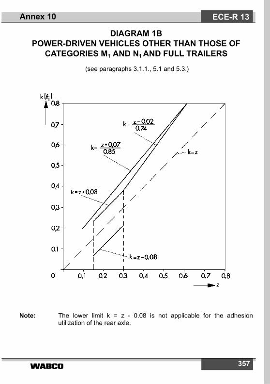
����� 357
DIAGRAM 1BPOWER-DRIVEN VEHICLES OTHER THAN THOSE OF
CATEGORIES M1 AND N1 AND FULL TRAILERS (see paragraphs 3.1.1., 5.1 and 5.3.)
Note: The lower limit k = z - 0.08 is not applicable for the adhesionutilization of the rear axle.
ECE-R 13Annex 10

�����358
DIAGRAM 1CVEHICLES OF CATEGORY N1
(with certain exceptions after October 1, 1990)(see paragraph 3.1.2.2. of this annex)
Note: The lower limit k = z - 0.08 is not applicable for the adhesionutilization of the rear axle.
ECE-R 13 Annex 10

����� 359
DIAGRAM 2TOWING VEHICLES AND TRAILERS (except tractors for semi-trailers and semi-trailers)
(see paragraph 3.1.5.1. of this annex)
Note: The relationships required by the diagram shall apply progressivelyfor intermediate states of loading between the laden and the unladenstates and shall be achieved by automatic means.
ECE-R 13Annex 10
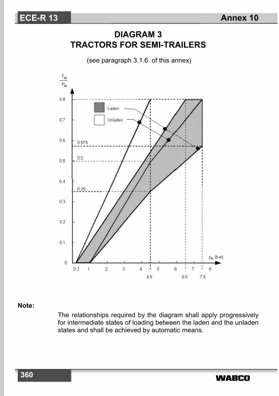
�����360
DIAGRAM 3TRACTORS FOR SEMI-TRAILERS
(see paragraph 3.1.6. of this annex)
Note:The relationships required by the diagram shall apply progressivelyfor intermediate states of loading between the laden and the unladenstates and shall be achieved by automatic means.
ECE-R 13 Annex 10

����� 361
DIAGRAM 4ASEMI-TRAILERS
(see paragraph 4 of this annex)
Note:The relation between the braking rate TR/PR and the control linepressure for the laden and unladen conditions is determined asfollows:The factors Kc (laden), Kv (unladen) are obtained by reference todiagram 4B. To determine the areas corresponding to the laden andunladen conditions, the values of the ordinates of the upper undlower limits of the hatched area in diagram 4A are multiplied by thefactors Kc and Kv respectively.
ECE-R 13Annex 10
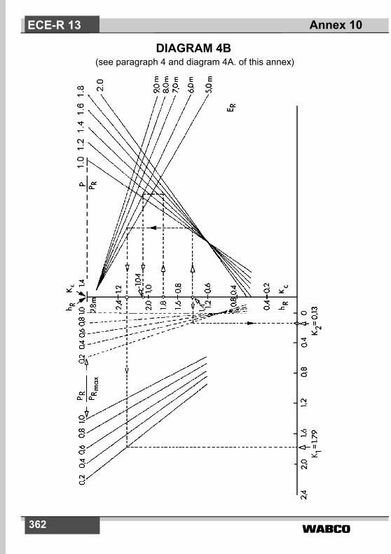
�����362
DIAGRAM 4B (see paragraph 4 and diagram 4A. of this annex)
ECE-R 13 Annex 10

����� 363
EXPLANATORY NOTE ON THE USE OF DIAGRAM 4B1. Formula from which diagram 4B is derived:
K = –
2. Description of method of use with practical example.
2.1. The broken lines shown on diagram 4B refer to the determination of the fac-tors Kc and Kv for the following vehicle, where:
In the following paragraphs the figures in parentheses relate only to thevehicle being used for the purpose of illustrating the method of using dia-gram 4B.
2.2. Calculation of ratios
(a) laden ( = 1.6 )
(b) unladen ( = 1.4 )
(c) unladen ( = 0.2 )
2.3. Determination of the correction factor when laden, Kc :
(a) Start at the appropriate value of hR (hR = 1.8 m)
Laden Unladen
P 24 tons (240 kN) 4.2 tons (42 kN)
PR 150 kN 30 kN
PRmax 150 kN 150 kN
hR 1.8 m 1.4 m
ER 6.0 m 6.0 m
1 7,0 7P, RPRmax------------------– 1 35, 0 96,
ER------------- 1 0, h� R 1 2 � P
PR-------,–+� �
� �–�
1 0,PR
PRmax------------------–
hR 1 0,� �–
2 5,---------------------------�
PPR-------
PPR-------
PPRmax-------------------
ECE-R 13Annex 10

�����364
(b) Move horizontally to the appropriate P/PR line(P/PR = 1.6)
(c) Move vertically to the appropriate ER line ( ER = 6.0 m )
(d) Move horizontally to the Kc scale; Kc is the laden correctionfactor required (Kc = 1.04).
2.4 Determination of the correction factor when unladen, KV :
2.4.1. Determination of the factor K2 :
(a) Start at appropriate hR (hR = 1.4 m)
(b) Move horizontally to the appropriate PR / PRmax line in thegroup of curves nearest to vertical axis PR / PRmax = 0.2)
(c) Move vertically to the horizontal axis and read off the value ofK2 (K2 = 0.13 m).
2.4.2. Determination of the factor K1:
(a) Start at the appropriate value of hR (hR = 1.4m)
(b) Move horizontally to the appropriate P / PR line ( P / PR = 1.4)
(c) Move vertically to the appropriate ER line (ER = 6.0 m)
(d) Move horizontally to the appropriate PR / PRmax line in thegroup of curves furthest from the vertical axis (PR / PRmax = 0.2)
(e) Move vertically to the horizontal axis and read off the value ofK1 (K1 = 1.79).
2.4.3. Determination of the factor KV :
The unladen correction factor KV is obtained from the following expression:
Kv = K1 – K2 (Kv = 1.6).
ECE-R 13 Annex 10

����� 365
DIAGRAM 5BRAKE LOAD SENSING DEVICE
(see paragraph 7.4 of this Annex)
Control data Vehicleloading
Axle No. 2
- load at the
ground (daN)
Inlet pressure
(bar)
Nominal outlet
pressure
(bar)
Laden
Unladen
10 000
1 500
6
6
6
2.5
ECE-R 13Annex 11
Laden
Unladen
F = 100 mmL = 150 mm

�����366
Annex 11
CASES IN WHICH TYPE-I AND/OR TYPE-II (OR TYPE-IIA) OR TYPE-III TESTS DO NOT
HAVE TO BE CARRIED OUT
1. Type-I and/or Type-II (or Type-IIA) or Type-III tests need not beperformed on a vehicle submitted for approval in the following cases:
1.1. The vehicle concerned is a power-driven vehicle or a trailer which asregards tyres, braking energy absorbed per axle, and mode of tyrefitting and brake assembly, is identical with respect to braking with apower-driven vehicle or a trailer which:
1.1.1. has passed the Type-I and/or Type-II (or Type-IIA) or Type-III test; and1.1.2. has been approved, with regard to the braking energy absorbed, for
mass per axle not lower than that of the vehicle concerned.
1.2. The vehicle concerned is a power-driven vehicle or a trailer whoseaxle or axles are, as regards tyres, braking energy absorbed peraxle, and mode of tyre fitting and brake assembly, identical withrespect to braking with an axle or axles which has individually passedthe Type-I and/or Type-II (or Type-IIA) or Type-III test for masses peraxle not lower than that of the vehicle concerned, provided that thebraking energy absorbed per axle does not exceed the energyabsorbed per axle in the reference test or tests carried out on theindividual axle.
1.3. The vehicle concerned is equipped with a retarder, other than theengine brake, identical with a retarder already tested under thefollowing conditions:
1.3.1. the retarder shall, by itself, in a test carried out on a gradient of atleast 6 per cent (Type-II test) or of at least 7 per cent (Type-IIA test),have stabilized a vehicle whose maximum mass at the time of thetest was not less than the maximum mass of the vehicle submittedfor approval;
ECE-R 13 Annex 11

����� 367
1.3.2. It shall be verified in the above test that the rotational speed of therotating parts of the retarder, when the vehicle submitted for approvalreaches a road speed of 30 km/h, is such that the retarding torque isnot less than that corresponding to the test referred to in paragraph1.3.1. above.
1.4. The vehicle concerned is a trailer equipped with air operated S-camor disc brakes 1) which satisfies the verification requirements ofappendix 2 to this annex relative to the control of characteristicscompared to the characteristics given in a report of a reference axletest as shown in appendix 3 to this annex.
2. The term ”identical“, as used in paragraphs 1.1., 1.2. and 1.3. above,means identical as regards the geometric and mechanicalcharacteristics and the materials used for the components of thevehicle referred to in those paragraphs.
3. Where the foregoing requirements are applied, the communicationconcerning approval (annex 2 to this Regulation) shall include thefollowing particulars:
3.1. In the case under paragraph 1.1., the approval number of the vehiclesubjected to the Type-I and/or Type-II (or Type-IIA) or Type-III test ofreference shall be entered.
3.2. In the case under paragraph 1.2., Table I in appendix 1 to this annexshall be completed;
3.3. In the case under paragraph 1.3., Table II in appendix 1 to this annexshall be completed.
3.4. If paragraph 1.4. is applicable, Table III in appendix 1 to this annexshall be completed.
4. Where the applicant for approval in a country Party to the Agreementapplying this Regulation refers to an approval granted in anothercountry Party to the Agreement applying this Regulation, he shallsubmit the documentation relating to that approval.
ECE-R 13Annex 11
1) Other brake designs may be approved upon presentation of equivalent infor-mation.
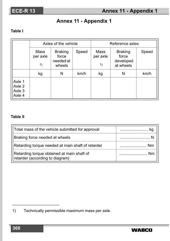
�����368
Annex 11 - Appendix 1
Table I
Table II
Axles of the vehicle Reference axles
Mass per axle
1)
Braking force
needed at wheels
Speed Mass per axle
1)
Braking force
developed at wheels
Speed
kg N km/h kg N km/h
Axle 1Axle 2Axle 3Axle 4
Total mass of the vehicle submitted for approval ......................... kg
Braking force needed at wheels ........................... N
Retarding torque needed at main shaft of retarder ........................ Nm
Retarding torque obtained at main shaft ofretarder (according to diagram)
......................... Nm
ECE-R 13 Annex 11 - Appendix 1
1) Technically permissible maximum mass per axle.
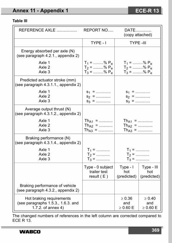
369
Table III
The changed numbers of references in the left column are corrected compared toECE R 13.
REFERENCE AXLE .................. REPORT NO..... DATE..............(copy attached)
TYPE - I TYPE -III
Energy absorbed per axle (N) (see paragraph 4.2.1., appendix 2)
Axle 1Axle 2Axle 3
T1 = .........% PeT2 = .........% PeT3 = .........% Pe
T1 = .........% PeT2 = .........% PeT3 = .........% Pe
Predicted actuator stroke (mm) (see paragraph 4.3.1.1., appendix 2)
Axle 1Axle 2Axle 3
s1 = .............s2 = .............s3 = .............
s1 = .............s2 = .............s3 = .............
Average output thrust (N)(see paragraph 4.3.1.2., appendix 2)
Axle 1Axle 2Axle 3
ThA1 = ............ThA2 = ............ThA3 = .............
ThA1 = .............ThA2 = .............ThA3 = .............
Braking performance (N)(see paragraph 4.3.1.4., appendix 2)
Axle 1Axle 2Axle 3
T1 = ............T2 = ............T3 = ............
T1 = ............T2 = ............T3 = ............
Braking performance of vehicle (see paragraph 4.3.2., appendix 2)
Type - 0 subject trailer test result ( E )
Type - I hot
(predicted)
Type - III hot
(predicted)
Hot braking requirements(see paragraphs 1.5.3., 1.6.3. and
1.7.2. of annex 4)
≥ 0.36and
≥ 0.60 E
≥ 0.40and
≥ 0.60 E
ECE-R 13Annex 11 - Appendix 1

�����370
Annex 11 - Appendix 2
ALTERNATIVE PROCEDURES FOR TYPE-I AND TYPE-III TESTS FOR TRAILER BRAKES
1. GENERAL1.1. In accordance with paragraph 1.4. of this annex, the Type-I or Type-
III test may be waived at the time of type approval of the vehicleprovided that the braking system components comply with therequirements of this appendix and that the resulting predicted brakingperformance meet the requirements of this Regulation for theappropriate vehicle category.
1.2. Tests carried out in accordance with the methods detailed in thisappendix shall be deemed to meet the above requirements.
1.3. Tests carried out in accordance with paragraph 3.6. of this appendixand the results reported in section 2 of appendix 3 or appendix 4shall be acceptable as a means of proving compliance with therequirements of paragraph 5.2.2.8.1. of this Regulation.
1.4. The adjustment of the brake(s) shall, prior to the Type-III test below,be set according to the following procedures as appropriate:
1.4.1. In the case of air operated trailer brake(s), the adjustment of thebrakes shall be such as to enable the automatic brake adjustmentdevice to function. For this purpose the actuator stroke shall beadjusted tos0 � 1.1 × sre-adjust (the upper limit shall not exceed a value recom-mended by the manufacturer),where:sre-adjust is the re-adjustment stroke according to the specifica-
tion of the manufacturer of the automatic brake adjust-ment device, i.e. the stroke, where it starts to re-adjustthe running clearance of the brake with an actuatorpressure of 1.0 bar.
Where, by agreement with the Technical Service, it is impractical tomeasure the actuator stroke, the initial setting shall be agreed withthe Technical Service.
From the above condition the brake shall be operated with anactuator pressure of 2.0 bar, 50 times in succession. This shall befollowed by a single brake application with an actuator pressure of� 6.5 bar.
ECE-R 13 Annex 11 - Appendix 2
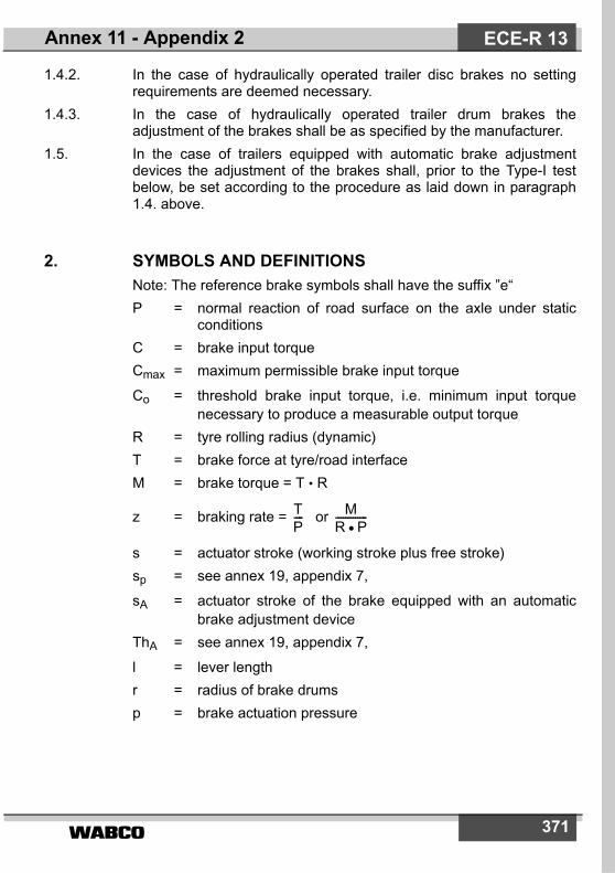
����� 371
1.4.2. In the case of hydraulically operated trailer disc brakes no settingrequirements are deemed necessary.
1.4.3. In the case of hydraulically operated trailer drum brakes theadjustment of the brakes shall be as specified by the manufacturer.
1.5. In the case of trailers equipped with automatic brake adjustmentdevices the adjustment of the brakes shall, prior to the Type-I testbelow, be set according to the procedure as laid down in paragraph1.4. above.
2. SYMBOLS AND DEFINITIONSNote: The reference brake symbols shall have the suffix ”e“P = normal reaction of road surface on the axle under static
conditionsC = brake input torqueCmax = maximum permissible brake input torque
Co = threshold brake input torque, i.e. minimum input torquenecessary to produce a measurable output torque
R = tyre rolling radius (dynamic)T = brake force at tyre/road interfaceM = brake torque = T • R
z = braking rate = or
s = actuator stroke (working stroke plus free stroke)sp = see annex 19, appendix 7,
sA = actuator stroke of the brake equipped with an automaticbrake adjustment device
ThA = see annex 19, appendix 7,
l = lever lengthr = radius of brake drumsp = brake actuation pressure
TP---- M
R P�-------------
ECE-R 13Annex 11 - Appendix 2

�����372
3. TEST METHODS
3.1. TRACK TESTS3.1.1. The brake performance tests should preferably be carried out on a
single axle only.3.1.2. The results of tests on a combination of axles may be used in
accordance with paragraph 1.1. of this annex provided that each axlecontributes equal braking energy input during the drag and hot braketests.
3.1.2.1. This is ensured if the following are identical for each axle: brakinggeometry, lining, wheel mounting, tyres, actuation and pressuredistribution in the actuators.
3.1.2.2. The documented result for a combination of axles will be the averagefor the number of axles, as though a single axle had been used.
3.1.3. The axle(s) should preferably be loaded with the maximum static axleload, though this is not essential provided that due allowance ismade during the tests for the difference in rolling resistance causedby a different load on the test axle(s).
3.1.4. Allowance shall be made for the effect of the increased rollingresistance resulting from a combination of vehicles being used tocarry out the tests.
3.1.5. The initial speed of the test shall be that prescribed. The final speedshall be calculated by the following formula:
v2 = v1 P0 P1+
P0 P1 P2+ +----------------------------------
ECE-R 13 Annex 11 - Appendix 2

����� 373
where:v1 = initial speed (km/h)
v2 = final speed (km/h)
P0 = mass of the towing vehicle (kg) under test conditions
P1 = part of the mass of the trailer borne by the unbraked axle(s) kg
P2 = part of the mass of the trailer borne by the braked axle(s) kg.
3.2. INERTIA DYNAMOMETER TESTS3.2.1. The test machine shall have a rotary inertia simulating that part of the
linear inertia of the vehicle mass acting upon one wheel, necessaryfor the cold performance and hot performance tests, and capable ofbeing operated at constant speed for the purpose of the testdescribed in paragraphs 3.5.2. and 3.5.3. of this appendix.
3.2.2. The test shall be carried out with a complete wheel, including thetyre, mounted on the moving part of the brake, as it would be on thevehicle. The inertia mass may be connected to the brake eitherdirectly or via the tyres and wheels.
3.2.3. Air cooling at a velocity and air flow direction simulating actualconditions may be used during the heating runs, the speed of theairflow being vair = 0.33 v
where:v = vehicle test speed at initiation of braking.The temperature of the cooling air shall be the ambient temperature.
3.2.4. Where the tyre rolling resistance is not automatically compensatedfor in the test, the torque applied to the brake shall be modified bysubtracting a torque equivalent to a rolling resistance coefficient of0.01.
3.3. ROLLING ROAD DYNAMOMETER TESTS3.3.1. The axle should preferably be loaded with the maximum static axle
mass though this is not essential provided that due allowance ismade during the tests for the difference in rolling resistance causedby a different mass on the test axle.
3.3.2. Air cooling at a velocity and air flow direction simulating actualconditions may be used during the heating runs, the speed of theairflow being vair = 0.33 v
where:v = vehicle test speed at initiation of braking.The temperature of the cooling air shall be the ambient temperature.
ECE-R 13Annex 11 - Appendix 2
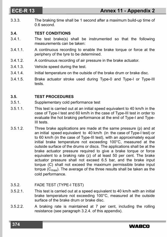
�����374
3.3.3. The braking time shall be 1 second after a maximum build-up time of0.6 second.
3.4. TEST CONDITIONS3.4.1. The test brake(s) shall be instrumented so that the following
measurements can be taken:3.4.1.1. A continuous recording to enable the brake torque or force at the
periphery of the tyre to be determined.3.4.1.2. A continuous recording of air pressure in the brake actuator.3.4.1.3. Vehicle speed during the test.3.4.1.4. Initial temperature on the outside of the brake drum or brake disc.3.4.1.5. Brake actuator stroke used during Type-0 and Type-I or Type-III
tests.
3.5. TEST PROCEDURES3.5.1. Supplementary cold performance test3.5.1.1. This test is carried out at an initial speed equivalent to 40 km/h in the
case of Type-I test and 60 km/h in the case of Type-III test in order toevaluate the hot braking performance at the end of Type-I and Type-III tests.
3.5.1.2. Three brake applications are made at the same pressure (p) and atan initial speed equivalent to 40 km/h (in the case of Type-I test) orto 60 km/h (in the case of Type-III test), with an approximately equalinitial brake temperature not exceeding 100°C, measured at theoutside surface of the drums or discs. The applications shall be at thebrake actuator pressure required to give a brake torque or forceequivalent to a braking rate (z) of at least 50 per cent. The brakeactuator pressure shall not exceed 6.5 bar, and the brake inputtorque (C) shall not exceed the maximum permissible brake inputtorque (Cmax). The average of the three results shall be taken as thecold performance.
3.5.2. FADE TEST (TYPE-I TEST)3.5.2.1. This test is carried out at a speed equivalent to 40 km/h with an initial
brake temperature not exceeding 100°C, measured at the outsidesurface of the brake drum or brake disc.
3.5.2.2. A braking rate is maintained at 7 per cent, including the rollingresistance (see paragraph 3.2.4. of this appendix).
ECE-R 13 Annex 11 - Appendix 2

����� 375
3.5.2.3. The test is made during 2 minutes and 33 seconds or during 1.7 kmat a vehicle speed of 40 km/h. If the test velocity cannot be achieved,then the duration of the test can be lengthened according toparagraph 1.5.2.2. of annex 4 to this Regulation.
3.5.2.4. Not later than 60 seconds after the end of the Type-I test, a hotperformance test is carried out in accordance with paragraph 1.5.3. ofannex 4 to this Regulation at an initial speed equivalent to 40 km/h.
The brake actuator pressure shall be that used during the Type-0 test.
3.5.3. FADE TEST (TYPE-III TEST)3.5.3.1. Test methods for repeated braking3.5.3.1.1. Track Tests (see annex 4, paragraph 1.7)3.5.3.1.2. Inertia Dynometer Test
For the bench test as in annex 11, appendix 2, paragraph 3.2., theconditions may be as for the road test according to paragraph 1.7.1.with:
v2 =
3.5.3.1.3. Rolling Road Dynometer Test
For the bench test as in annex 11, appendix 2, paragraph 3.3., theconditions shall be as follows:Number of brake applications 20Duration of braking cycle(braking time 25 s and recovery time 35 s) 60 sTest speed 30 km/hBraking rate 0.06Rolling resistance 0.01
3.5.3.2. Not later than 60 seconds after the end of the Type-III test a hotperformance test is carried out in accordance with paragraph 1.7.2. ofannex 4 to this Regulation. The brake actuator pressure shall be thatused during the Type-0 test.
3.6. PERFORMANCE REQUIREMENTS FOR AUTOMATIC BRAKE ADJUSTMENT DEVICES
3.6.1. The following requirements shall apply to an automatic brakeadjustment device which is installed on a brake, the performance ofwhich is being verified according to the provisions of this appendix.
v12------
ECE-R 13Annex 11 - Appendix 2

�����376
On completion of the tests defined in paragraphs 3.5.2.4. (Type-I test)or 3.5.3.2 (Type-III test) above, the requirements of paragraph 3.6.3.below shall be verified.
3.6.2. The following requirements shall apply to an alternative automaticbrake adjustment device installed on a brake for which an appendix 3test report already exists.
3.6.2.1. Brake performanceFollowing heating of the brake(s) carried out in accordance with theprocedures defined in paragraphs 3.5.2. (Type-I test) or 3.5.3 (Type-IIItest), as appropriate, one of the following provisions shall apply:a) The hot performance of the service braking system shall be
� 80 per cent of the prescribed Type-0 performance; orb) The brake shall be applied with a brake actuator pressure as
used during the Type-0 test; at this pressure the total actuatorstroke (sA) shall be measured and shall be � 0.9 sp value of thebrake chamber.
sp = The effective stroke means the stroke at which the out-putthrust is 90 per cent of the average thrust (ThA) - seeparagraph 2. of annex 11 - appendix 2 to this Regulation.
3.6.2.2. On completion of the tests defined in paragraph 3.6.2.1. above therequirements of paragraph 3.6.3. below shall be verified.
3.6.3. Free running testAfter completing the tests defined in paragraphs 3.6.1. or 3.6.2. above,as applicable, the brake(s) shall be allowed to cool to a temperaturerepresentative of a cold brake (i.e. � 100°C) and it should be verifiedthat the trailer/wheel(s) is capable of free running by fulfilling one of thefollowing conditions:a) Wheels are running freely (i.e. wheels can be rotated by hand)b) It is ascertained that at a constant speed equivalent to v = 60
km/h with the brake(s) released the asymptotic temperatureshall not exceed a drum/disc temperature increase of 80°C,then this residual brake moment is regarded as acceptable.
3.7. TEST REPORT3.7.1. The result of tests carried out in accordance with paragraphs 3.5. and
3.6.1. of this appendix shall be reported on a form, a model of whichis shown in appendix 3 to this annex.
3.7.2. The brake and the axle shall be identified. Particulars of the brakes,
ECE-R 13 Annex 11 - Appendix 2

����� 377
the axle, the technically permissible mass and the number of thecorresponding appendix 3 test report shall be marked on the axle.
3.7.3. In the case of a brake installed with an alternative brake adjustmentdevice the results of tests carried out in accordance with paragraph3.6.2. of this appendix shall be reported on a form a model of which isshown in appendix 4 to this annex.
4. VERIFICATION
4.1. Verification of componentsThe brake specification of the vehicle to be type approved shall beverified by satisfying each of the following design criteria:
Item Criteria
4.1.1. (a) Brake drum cylindrical section
(b) Brake drum or brake discmaterial
(c) Brake drum or brake disc mass
No Change allowed
No Change allowed
May increase up to + 20 per cent from the reference drum or disc mass
4.1.2. (a) Proximity of wheel to outsidesurface of brake drum or outside diameter of brake disc(dimension E)
(b) Part of brake drum or brakedisc not covered by wheel (dimension F)
Tolerances to be determined by the Technical Service conducting the tests.
4.1.3. (a) Brake lining or brake pad material
(b) Brake lining or brake pad width(c) Brake lining or brake pad
thickness(d) Brake lining or brake pad
actual surface area(e) Brake lining or brake pad
method of attachment
))))) No change allowed))))
ECE-R 13Annex 11 - Appendix 2
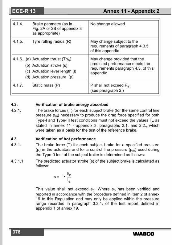
�����378
4.2. Verification of brake energy absorbed4.2.1. The brake forces (T) for each subject brake (for the same control line
pressure pm) necessary to produce the drag force specified for bothType-I and Type-III test conditions must not exceed the values Te asstated in annex 11 - appendix 3, paragraphs 2.1. and 2.2., whichwere taken as a basis for the test of the reference brake.
4.3. Verification of hot performance4.3.1. The brake force (T) for each subject brake for a specified pressure
(p) in the actuators and for a control line pressure (pm) used duringthe Type-0 test of the subject trailer is determined as follows:
4.3.1.1 The predicted actuator stroke (s) of the subject brake is calculated asfollows:
s = l •
This value shall not exceed sp. Where sp has been verified andreported in accordance with the procedure defined in item 2 of annex19 to this Regulation and may only be applied within the pressurerange recorded in paragraph 3.3.1. of the test report defined inappendix 1 of annex 19.
4.1.4. Brake geometry (as inFig. 2A or 2B of appendix 3 as appropriate)
No change allowed
4.1.5. Tyre rolling radius (R) May change subject to the requirements of paragraph 4.3.5. of this appendix
4.1.6. (a) Actuation thrust (ThA)(b) Actuation stroke (s)(c) Actuation lever length (l)(d) Actuation pressure (p)
May change provided that the predicted performance meets the requirements paragraph 4.3. of thisappendix
4.1.7. Static mass (P) P shall not exceed Pe (see paragraph 2.)
sele------
ECE-R 13 Annex 11 - Appendix 2

����� 379
4.3.1.2. The average thrust output (ThA) of the actuator fitted to the subjectbrake at the pressure specified in paragraph 4.3.1. above ismeasured.
4.3.1.3. The brake input torque (C) is then calculated as follows:C = ThA • l
C shall not exceed Cmax.
4.3.1.4. The predicted brake performance for the subject brake is given by:
T = (Te - 0.01 • Pe) + 0.01 • P
R shall not be less than 0.8 Re.
4.3.2. The predicted brake performance for the subject trailer is given by:
4.3.3. The hot performances following the Type-I or Type-III tests shall bedetermined in accordance with paragraphs 4.3.1.1. to 4.3.1.4. Theresulting predictions given by paragraph 4.3.2. above must satisfy therequirements of this Regulation for the subject trailer. The value usedfor ”the figure recorded in the Type-0 test as prescribed in paragraph1.5.3. of annex 4“, shall be the figure recorded in the Type-0 test ofthe subject trailer.
C Co–� �
Ce Coe–� �----------------------------
ReR-------�
TRPR------- �T
�P---------=
ECE-R 13Annex 11 - Appendix 2

�����380
Annex 11 - Appendix 3
MODEL TEST REPORT FORM AS PRESCRIBED IN PARAGRAPH 3.7.1. AND 3.7.2. OF APPENDIX 2
TO THIS ANNEX
TEST REPORT NO. ..................
1. IDENTIFICATION1.1. Axle:
Manufacturer (name and address)Make . . . . . . . . . . . . . . . . . . . . . . . . . . . . . . . . . . . . . . . . . .Type . . . . . . . . . . . . . . . . . . . . . . . . . . . . . . . . . . . . . . . . . .Model . . . . . . . . . . . . . . . . . . . . . . . . . . . . . . . . . . . . . . . . .Technically permissible axle load (Pe) . . . . . . . . . . . . . . . . daN
1.2. Brake:Manufacturer (name and address)Make . . . . . . . . . . . . . . . . . . . . . . . . . . . . . . . . . . . . . . . . . .Type . . . . . . . . . . . . . . . . . . . . . . . . . . . . . . . . . . . . . . . . . .Model . . . . . . . . . . . . . . . . . . . . . . . . . . . . . . . . . . . . . . . . .Technically permissible brake input torque Cmax . . . . . . . . . . . . . . . . . . . . . . . . . . . . . . . .Automatic brake adjustment drive: integrated / non-integrated 1). . . . . . . . . . . . . . . . . . . . . . . .Brake drum or Brake disc 1) :Internal diameter of drum or outside diameter of disc 1) . . .Effective radius . . . . . . . . . . . . . . . . . . . . . . . . . . . . . . . . .Thickness 2) . . . . . . . . . . . . . . . . . . . . . . . . . . . . . . . . . . . .Mass . . . . . . . . . . . . . . . . . . . . . . . . . . . . . . . . . . . . . . . . . .Material . . . . . . . . . . . . . . . . . . . . . . . . . . . . . . . . . . . . . . . .
Brake lining or pad 1): Manufacturer . . . . . . . . . . . . . . . . . . . . . . . . . . . . . . . . .Type . . . . . . . . . . . . . . . . . . . . . . . . . . . . . . . . . . . . . . . .
ECE-R 13 Annex 11 - Appendix 3

����� 381
Identification (must be visible when the lining /pad is mountedon the brake shoe / backing plate) . . . . . . . . . . . . . . . . . . Width . . . . . . . . . . . . . . . . . . . . . . . . . . . . . . . . . . . . . . . . . Thickness . . . . . . . . . . . . . . . . . . . . . . . . . . . . . . . . . . . . . Surface area . . . . . . . . . . . . . . . . . . . . . . . . . . . . . . . . . . . Method of attachment . . . . . . . . . . . . . . . . . . . . . . . . . . . . Brake geometry, attach dimension drawing as follows:Drum brakes see fig. 2A of this appendixDisc brakes see fig. 2B of this appendix
1.3. Wheel(s):Single/Twin 1) Rim diameter (D) . . . . . . . . . . . . . . . . . . . . . . . . . . . . . . . . (Attach dimensioned drawing as in fig. 1A or fig 1B of thisappendix, as appropriate.
1.4. Tyres:Reference rolling radius (Re) at reference reaction (Pe) . . . . . . . . . . . . . . . . . . . . . . . . . . . . . . . . . . .
1.5. Actuator:Manufacturer . . . . . . . . . . . . . . . . . . . . . . . . . . . . . . . . . . . Type (cylinder/diaphragm)1)
Model . . . . . . . . . . . . . . . . . . . . . . . . . . . . . . . . . . . . . . . . Lever length (le) . . . . . . . . . . . . . . . . . . . . . . . . . . . . . . . . .
1.6. 3) Automatic brake adjustment device (not applicable in the case of integrated automatic brake adjustment device)Manufacturer (name and address): . . . . . . . . . . . . . . . . . . Make: . . . . . . . . . . . . . . . . . . . . . . . . . . . . . . . . . . . . . . . . Type: . . . . . . . . . . . . . . . . . . . . . . . . . . . . . . . . . . . . . . . . . Version: . . . . . . . . . . . . . . . . . . . . . . . . . . . . . . . . . . . . . . .
ECE-R 13Annex 11 - Appendix 3
1) Strike out what does not apply2) Applies to disc brakes only3) Only to be completed when an automatic brake wear adjustment device
is installed

�����382
2. RECORD OF TEST RESULTS 5)
(corrected to take account of rolling resistance � 0,01 . Pe
2.1. In the case of vehicles of categories O2 and O3
2.2. In the case of vehicles of category O4:
TEST TYPE 0 I
Annex 11, Appendix 2, Para.: 3.5.1.2. 3.5.2.2./3. 3.5.2.4.
Test speedBrake actuator pressure peBraking timeBrake force developed TeBrake efficiency Te/9,81PeActuator stroke seBrake input torque CeBrake input torque Coe
km/hbar minN – mm Nm Nm
40
–
40–
2.55
– – –
40 ––
TEST TYPE 0 III
Annex 11, Appendix 2, Para.: 3.5.1.2. 3.5.3.1. 3.5.3.2.
Test speed initial finalBrake actuator pressure peNumber of brake applicationsDuration of braking cycleBrake force developed TeBrake efficiency Te/9,81PeActuator stroke seBrake input torque CeBrake input torque Coe
km/hkm/hbar –sN – mm Nm Nm
60
––
– 2060
– – –
60 ––
ECE-R 13 Annex 11 - Appendix 3
5) Track Test/Inertia Dynamometer Test/Rolling Road Dynamometer Test (delete where not applicable)

����� 383
2.3. This item is to be completed only when the brake has been subject tothe test procedure defined in paragraph 4. of annex 19 to thisRegulation to verify the cold performance characteristics of the brakeby means of the brake factor (BF). Where the brake factor is definedas output to input amplification ratio of the brake.
2.3.1. Brake factor BF:
3. Performance of the automatic brake adjustment device(if applicable)
3.1. Free running according to paragraph 3.6.3. of annex 11, appendix 2: yes / no 1)
4. This test has been carried out and the results reported in accordancewith appendix 2 to annex 11 and where appropriate paragraph 4. ofannex 19 to ECE Regulation No. 13 as last amended by the .....series of amendments
Technical Service 4) carrying out the test
Signed: .......................... Date: ..................
5. Approval Authority 4)
6. 3) At the end of test defined in paragraph 3.6. of annex 11, appendix 2the requirements of paragraph 5.2.2.8.1. of Regulation No. 13 weredeemed to be fulfilled / not fulfilled 1)
Signed: ................................. Date: ......................................
Annex 11 - Appendix 3 ECE-R 13
1) Strike out what does not apply.3) Only to be completed when an automatic brake wear adjustment device is
installed4) To be signed by different persons even when the Technical Service and
Approval Authority are the same or alternatively, a separate ApprovalAuthority authorisation issued with the report.
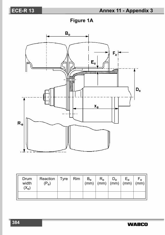
�����384
Figure 1A
Drum width (Xe)
Reaction(Pe)
Tyre Rim Be(mm)
Re(mm)
De(mm)
Ee(mm)
Fe(mm)
Annex 11 - Appendix 3ECE-R 13

����� 385
Figure 1B
Be(mm)
De(mm)
Ee(mm)
Fe(mm)
Re(mm)
Re
Fe
De
Ee
Be
Annex 11 - Appendix 3 ECE-R 13

�����386
Figure 2ABrake Geometry
All dimensions in mm except �oe, �1e and Fe.Fe = useful braking surface per brake (cm2).
Type ofbrake
ae he ce de ee �oe �1e be re Fe S1e S2e S3e
Annex 11 - Appendix 3ECE-R 13

����� 387
Figure 2B
le(mm)
ee(mm)
de(mm)
xe(mm)
re(mm)
be(mm)
Fe(mm)
A
re
be
dede
le
ee
RotorThickness
Total padarea / brake
Fe
xe
Annex 11 - Appendix 3 ECE-R 13

�����388
Annex 11 - Appendix 4
MODEL TEST FOR AN ALTERNATIVE AUTOMATIC BRAKE ADJUSTMENT DEVICE FORM AS PRESCRIBED IN
PARAGRAPH 3.7.3. OF APPENDIX 2 TO THIS ANNEXTEST REPORT No. ............................
1. IDENTIFICATION1.1. Axle:
Make: ..................................................................................................Type: ...................................................................................................Model: ............................................................Technically permissible axle load (Pe) ......................................... daN
Annex 11 Appendix 3 Test Report No. ..................
1.2. Brake:Make: ..................................................................................................Type: ...................................................................................................Model: .................................................................................................Brake lining: ........................................................................................Make/Type: .........................................................................................
1.3. Actuation:Manufacturer: .....................................................................................Type (cylinder/diaphragm) 1): . ............................................................Model: .................................................................................................Lever length (l): ............................................................................ mm
1.4. Automatic brake adjustment device:Manufacturer (name and address): ....................................................Make: ..................................................................................................Type: ...................................................................................................Version: ..............................................................................................
Annex 11 - Appendix 4ECE-R 13
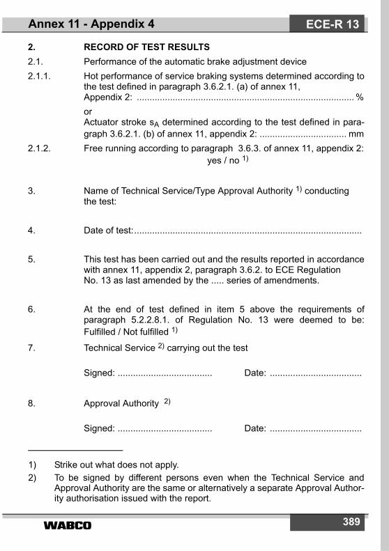
����� 389
2. RECORD OF TEST RESULTS2.1. Performance of the automatic brake adjustment device2.1.1. Hot performance of service braking systems determined according to
the test defined in paragraph 3.6.2.1. (a) of annex 11, Appendix 2: ..................................................................................... %orActuator stroke sA determined according to the test defined in para-graph 3.6.2.1. (b) of annex 11, appendix 2: .................................. mm
2.1.2. Free running according to paragraph 3.6.3. of annex 11, appendix 2:yes / no 1)
3. Name of Technical Service/Type Approval Authority 1) conducting the test:
4. Date of test:.........................................................................................
5. This test has been carried out and the results reported in accordancewith annex 11, appendix 2, paragraph 3.6.2. to ECE Regulation No. 13 as last amended by the ..... series of amendments.
6. At the end of test defined in item 5 above the requirements ofparagraph 5.2.2.8.1. of Regulation No. 13 were deemed to be:Fulfilled / Not fulfilled 1)
7. Technical Service 2) carrying out the test
Signed: ..................................... Date: ....................................
8. Approval Authority 2)
Signed: ..................................... Date: ....................................
Annex 11 - Appendix 4 ECE-R 13
1) Strike out what does not apply.2) To be signed by different persons even when the Technical Service and
Approval Authority are the same or alternatively a separate Approval Author-ity authorisation issued with the report.

�����390
Annex 12
CONDITIONS GOVERNING THE TESTING OF VEHICLES EQUIPPED WITH INERTIA (OVERRUN) BRAKING SYSTEMS
1. GENERAL PROVISIONS1.1. The inertia (overrun) braking system of a trailer comprises the control
device, the transmission and the wheel brakes, hereinafter called”brakes“.
1.2. The control device is the aggregate of the components integral withthe traction device (coupling head).
1.3. The transmission is the aggregate of the components comprisedbetween the last part of the coupling head and the first part of thebrake.
1.4. The ”brake“ is the part in which the forces opposing the movement ofthe vehicle develop. The first part of the brake is either the leveractuating the brake cam or similar components (mechanical-transmission inertia braking system), or the brake cylinder (hydraulic-transmission inertia braking system).
1.5. Braking systems in which accumulated energy (e.g. electric,pneumatic or hydraulic energy) is transmitted to the trailer by thetowing vehicle and is controlled only by the thrust on the coupling donot constitute inertia braking systems within the meaning of thisRegulation.
1.6. Tests1.6.1. Determination of essential components of the brake.1.6.2. Determination of essential components of the control device and
verification of the latter's conformity with the provisions of thisRegulation.
1.6.3. Checking on the vehicle:– the compatibility of the control device and the brake; and– the transmission.
2. SYMBOLS AND DEFINITIONS2.1. Units used2.1.1. Mass: kg;2.1.2. Force: N;
Annex 12ECE-R 13

����� 391
2.1.3. Acceleration due to gravity: g = 10 m/s2
2.1.4. Torques and moments: Nm;
2.1.5. Areas: cm2;2.1.6. Pressures: bar;2.1.7. Lengths: unit specified in each case.2.2. Symbols valid for all types of brakes (see figure 1 of appendix 1 to
this annex)2.2.1. GA: trailer's technically permissible ”maximum mass“ as declared by
the manufacturer;2.2.2. G'A: trailer's ”maximum mass“ capable of being braked by the con-
trol device, as declared by the manufacturer;2.2.3. GB: trailer's ”maximum mass“ capable of being braked by joint oper-
ation of all of the trailer's brakesGB = n • GBo ;
2.2.4. GBo: fraction of trailer's permissible ”maximum mass“ capable ofbeing braked by one brake, as declared by the manufacturer;
2.2.5. B*: required braking force;2.2.6. B: required braking force taking account of rolling resistance;2.2.7. D*: permissible thrust on coupling;2.2.8. D: thrust on coupling;2.2.9. P': control device output force;2.2.10. K: supplementary force of control device, conventionally desig-
nated by the force D corresponding to the point of intersectionwith the axis of the abscissae of the extrapolated curve express-ing P' in terms of D, measured with the device in the mid-travelposition (see figures 2 and 3 of appendix 1 to this annex);
2.2.11. KA: stress threshold of control device, i.e. the maximum thrust on thecoupling head which can be applied for a short time without plac-ing any stress on the output side of the control device. The sym-bol KA is conventionally applied to the force measured when thecoupling head begins to be pushed home at a speed of 10 to 15mm/s, the control device transmission being uncoupled;
2.2.12. D1: the maximum force applied to the coupling head when it isbeing pushed home at a speed of s mm/s ± 10%, the transmis-sion being uncoupled;
2.2.13. D2: the maximum force applied to the coupling head when it is beingpulled at a speed of s mm/s ± 10% out of the position of maxi-
Annex 12 ECE-R 13

�����392
mum compression, the transmission being uncoupled;2.2.14. �Ho: efficiency of inertia control device;2.2.15. �H1: efficiency of transmission system;2.2.16. �H: overall efficiency of control device and transmission
�H = �Ho • �H1 ;
2.2.17. s: travel of control in millimetres;2.2.18. s': effective (useful) travel of control in millimetres, determined as
required by paragraph 9.4. of this annex;2.2.19. s": spare travel of master cylinder, measured in millimetres at cou-
pling head;2.2.19.1. sHz: stroke of the master cylinder in millimetres according to figure 8
of appendix 1 to this annex;2.2.19.2. s"Hz: spare travel of the master cylinder in millimetres at piston rod
according to figure 8;2.2.20. so: loss of travel, i.e. travel in millimetres of the coupling head when
the latter is so actuated as to move from 300 mm above to 300mm below the horizontal, the transmission remaining stationary;
2.2.21. 2sB: brake-shoe lift (brake-shoe application travel), in millimetres,measured on diameter parallel to applying device, the brakesnot being adjusted during the test;
2.2.22. 2sB*: minimum brake shoe centre lift (minimum brake shoe applica-tion travel) (in millimetres) for wheel brakes with drum brakes
2sB* = 2.4 + ;
2r being the diameter of the brake drum in millimetres; (seeAppendix 1, Figure 4, to this Annex)for wheel brakes with disc brakes with hydraulical transmission
2sB* = 1.1 + ;
where:V60 =fluid volume absorbed of one wheel brake at a pressure corre-
sponding to a braking force of 1.2 B* = 0.6 • GBo and a max.tyre radius.and2rA = outer diameter of brake disc.(V60 in cm3, FRZ in cm2 and rA in mm)
41000------------- 2r�
10 V60�
FRZ--------------------- 1
1000------------- 2rA�+
Annex 12ECE-R 13
����� 393
2.2.23. M*: Braking torque as specified by the manufacturer in paragraph 5.of appendix 3. This braking torque shall produce at least, theprescribed braking force B*;
2.2.23.1. MT: Test braking torque in the case when no overload protector isfitted (according to paragraph 6.2.1. below);
2.2.24. R: dynamic tyre rolling radius (m);2.2.25. n: number of brakes.2.2.26 Mr: Maximum braking torque resulting from the maximum permissi-
ble travel sr or the maximum permissible fluid volume Vr whenthe trailer moves rearward (including rolling resistance = 0.01·g·GBo);
2.2.27. sr: Maximum permissible travel at the brake control lever when thetrailer moves rearward;
2.2.28. Vr: Maximum permissible fluid volume absorbed by one brakingwheel when the trailer moves rearward;
2.3. Symbols valid for mechanical-transmission braking systems (seefigure 5 of appendix 1 to this annex);
2.3.1. iH0: reduction ratio between travel of coupling head and travel oflever at output side of control device;
2.3.2. iH1: reduction ratio between travel of lever at output side of controldevice and travel of brake lever (gearing down of transmission);
2.3.3. iH: reduction ratio between travel of coupling head and travel ofbrake lever
iH = iHo • iH1
2.3.4. ig: reduction ratio between travel of brake lever and lift (applicationtravel) at brake-shoe centre (see figure 4 of appendix 1 to thisannex);
2.3.5. P: Force applied to the brake control lever; (see figure 4 of appen-dix 1 to this annex);
2.3.6. Po: Brake-retraction force when the trailer moves forward; i.e., inthe graph of M = f (P), the value of the force P at the point ofintersection of the extrapolation of this function with theabscissa (see figure 6 of appendix 1 to this annex);
2.3.6.1. Por: brake-retraction force when the trailer moves rearward (see fig-ure 6 of appendix 1 to this annex);
2.3.7. P*: Force applied to the brake control lever to produce the brakingforce B*;
Annex 12 ECE-R 13

�����394
2.3.8. PT: test force according to paragraph 6.2.1.;2.3.9. : characteristic of the brake when the trailer moves forward as
defined from:M = (P - Po)
2.3.9.1. r: characteristic of the brake when the trailer moves rearward asdefined from:
Mr = r (Pr - Por)
2.4. Symbols valid for hydraulic-transmission braking systems (see figure8 of appendix 1 to this annex)
2.4.1. ih: reduction ratio between travel of coupling head and travel ofpiston in master cylinder;
2.4.2. i'g: reduction ratio between travel of cylinder thrust point and lift(application travel) of brake-shoe centre;
2.4.3. FRZ: Surface area of piston of one wheel cylinder for drum brake(s);for disc brake(s), sum of the surface area of the caliper pis-ton(s) on one side of the disc.
2.4.4. FHZ: surface area of piston in master cylinder;2.4.5. p: hydraulic pressure in brake cylinder;2.4.6. po: retraction pressure in brake cylinder when the trailer moves for-
ward; i.e., in graph of M = f (p), the value of the pressure p atthe point of intersection of the extrapolation of this function withthe abscissa (see figure 7 of appendix 1 to this annex);
2.4.6.1. por: brake retraction pressure when the trailer moves rearward (seefigure 7 of appendix 1 to this annex);
2.4.7. p*: Hydraulic pressure in the brake cylinder to produce the brakingforce B*;
2.4.8. pT: Test pressure according to paragraph 6.2.1.:2.4.9. ': characteristic of the brake when the trailer moves forward as
defined from:M = ' (p - po)
2.4.9.1. 'r: characteristic of the brake when the trailer moves rearward asdefined from:
Mr = r (pr - por)
2.5. Symbols with respect to the braking requirements relating to overloadprotectors
2.5.1. Dop: Application force at the input side of the control device, at whichthe overload protector is activated
Annex 12ECE-R 13

����� 395
2.5.2. Mop: Brake torque at which the overload protector is activated (asdeclared by the manufacturer)
2.5.3. MTop: Minimum test braking torque in the case when an overloadprotector is fitted (according to paragraph 6.2.2.2.)
2.5.4. Pop_min: Force applied to the brake at which the overload protector isactivated (according to paragraph 6.2.2.1.)
2.5.5. Pop_max: Maximum force (when the coupling head is pushed fullyhome) which is applied by the overload protector to thebrake (according to paragraph 6.2.2.3.)
2.5.6. pop_min: Pressure applied to the brake at which the overload protec-tor is activated (according to paragraph 6.2.2.1.)
2.5.7. pop_max: Maximum hydraulic pressure (when the coupling head ispushed fully home) which is applied by the overload protec-tor to the brake actuator (according to paragraph 6.2.2.3.)
2.5.8. PTop: Minimum test brake force in the case when an overload pro-tector is fitted (according to paragraph 6.2.2.2.)
2.5.9. pTop: Minimum test brake pressure in the case when an overloadprotector is fitted (according to paragraph 6.2.2.2.)
3. GENERAL REQUIREMENTS3.1. The transmission of force from the coupling head to the trailer's
brakes must be effected either by rod linkage or by one or morefluids. However, a sheathed cable (Bowden cable) may provide partof the transmission; this part must be as short as possible.
3.2. All bolts at joints must be adequately protected. In addition, thesejoints must be either self-lubricating or readily accessible forlubrication.
3.3. Inertia braking devices must be so arranged that in the case whenthe coupling head travels to its fullest extent, no part of thetransmission seizes, undergoes permanent distortion or breaks. Thismust be checked by uncoupling the end of the transmission from thebrake control levers.
3.4. The inertia braking system must allow the trailer to be reversed withthe towing vehicle without imposing a sustained drag force exceeding0.08 g • GA. Devices used for this purpose must act automaticallyand disengage automatically when the trailer moves forward.
3.5. Any special device incorporated for the purpose of paragraph 3.4. of
Annex 12 ECE-R 13

�����396
this annex shall be such that the parking performance when facing upa gradient shall not be adversely affected.
3.6. Inertia braking systems may incorporate overload protectors. Theymust not be activated at a force of less than Dop = 1.2 • D* (whenfitted at the control device) or at a force of less than Pop = 1.2 • P* orat a pressure of less than pop = 1.2 • p* (when fitted at the wheelbrake) where the force P* or the pressure p* corresponds to a brakingforce of B* = 0,5 • g • GBo.
4. REQUIREMENTS FOR CONTROL DEVICES4.1. The sliding members of the control device must be long enough to
enable the full travel to be used even when the trailer is coupled.4.2. The sliding members must be protected by a bellows or some
equivalent device. They must either be lubricated or be constructedof self-lubricating materials. The surfaces in frictional contact must bemade from a material such that there is neither electrochemicaltorque nor any mechanical incompatibility liable to cause the slidingmembers to seize.
4.3. The stress threshold (KA) of the control device must be not less than0.02 g • G'A and not more than 0.04 g • G'A.
4.4. The maximum insertion force D1 may not exceed 0.10 g • G'A intrailers with rigid drawbars and 0.067 g • G'A in multi-axled trailerswith pivoted drawbars.
4.5. The maximum tractive force D2 must be not less than 0.1 g • G'A andnot more than 0.5 g • G'A.
5. TESTS AND MEASUREMENTS TO BE CARRIED OUT ON THE CONTROL DEVICES
5.1. Control devices submitted to the Technical Service conducting thetests must be checked for conformity with the requirements ofparagraphs 3 and 4 of this annex.
5.2. The following shall be measured in respect of all types of brakes:5.2.1. travel s and effective travel s';5.2.2. supplementary force K;5.2.3. stress threshold KA;
5.2.4. insertion force D1:
5.2.5. tractive force D2.
Annex 12ECE-R 13

����� 397
5.3. In the case of mechanical-transmission inertia braking systems, thefollowing should be determined:
5.3.1. the reduction ratio iHo measured at the mid-travel position of thecontrol;
5.3.2. the control-device output force P' as a function of the thrust D on thedrawbar.The supplementary force K and the efficiency are derived from therepresentative curve obtained from these measurements
�H0 = (see figure 2 of appendix 1 to this annex)
5.4. In the case of hydraulic-transmission inertia braking systems, thefollowing should be determined:
5.4.1. the reduction ratio ih measured at the mid-travel position of the control;
5.4.2. the master cylinder output pressure p as a function of the thrust D onthe drawbar and of the surface area FHZ of the master-cylinderpiston, as specified by the manufacturer. The supplementary force Kand the efficiency are derived from the representative curve obtainedfrom these measurements
�H0 = (see figure 3 of appendix 1 to this annex)
5.4.3. the spare travel of the master cylinder ”s“, as referred to in paragraph2.2.19. of this annex.
5.4.4. surface area FHZ of the piston in the master cylinder.
5.4.5. stroke sHz of master cylinder (in millimetres).
5.4.6. spare travel s"Hz of master cylinder (in millimetres).
5.5. In the case of inertia braking system on multi-axled trailers withpivoted drawbar, the loss of travel so referred to in paragraph 9.4.1.of this annex should be measured.
6. REQUIREMENTS FOR BRAKES6.1. In addition to the brakes to be checked, the manufacturer shall
submit to the Technical Service conducting the tests, drawings of thebrakes showing the type, dimensions and material of the essentialcomponents and the make and type of the linings. In the case of
1iH0-------- P
D K–--------------�
1ih----
p FHZ�
D K–-------------------�
Annex 12 ECE-R 13

�����398
hydraulic brakes, these drawings shall show the surface area FRZ ofthe brake cylinders. The manufacturer shall also specify the brakingtorque M* and the mass GBo defined in paragraph 2.2.4. of thisannex.
6.2. Testing conditions6.2.1. In the case when an overload protector is neither fitted nor intended
to be fitted within the inertia (overrun) braking system, the wheelbrake shall be tested with the following test forces or pressures:PT = 1.8 P* or pT = 1.8 p* and MT = 1.8 M* as appropriate.
6.2.2. In the case when an overload protector is fitted or intended to befitted within the inertia (overrun) braking system, the wheel brakeshall be tested with the following test forces or pressures:
6.2.2.1. The minimum design values for overload protector shall be specifiedby the manufacturer and shall not be less thanPop = 1.2 P* or pop = 1.2 p*
6.2.2.2. The ranges of minimum test force PTop or minimum test pressurepTop and the minimum test torque MTop are:
PTop = 1.1 to 1.2 P* or pTop = 1.1 to 1.2 p* ,and MTop = 1.1 to 1.2 M*
6.2.2.3. The maximum values (Pop_max or pop_max) for the overload protectorshall be specified by the manufacturer and shall not be more than PTor pT respectively.
7. TESTS AND MEASUREMENTS TO BE CARRIED OUT ON THE BRAKES
7.1. Brakes and components submitted to the Technical Serviceconducting the tests must be tested for conformity with therequirements of paragraph 6 of this annex.
7.2. The following should be determined:7.2.1. The minimum brake-shoe lift (minimum brake-shoe application
travel), 2sB*;
7.2.2. The brake-shoe lift (brake-shoe application travel) 2sB (which mustbe greater than 2sB*);
7.3. In the case of mechanical brakes, the following shall be determined:7.3.1. reduction ratio ig (see figure 4 of appendix 1 to this annex)
7.3.2. Force P* for braking torque M*
Annex 12ECE-R 13
����� 399
7.3.3. Torque M* as a function of the force P* applied to the control leverin mechanical-transmission systems. The rotational speed of thebraking surfaces shall correspond to an initial vehicle speed of 60km/h when the trailer moves forward and 6 km/h when the trailermoves rearward. The following shall be derived from the curveobtained from these measurements (see figure 6 of appendix 1 to thisannex):
7.3.3.1. The brake-retraction force Po and the characteristic value when thetrailer moves forward.
7.3.3.2. The brake-retraction force Por and the characteristic value r whenthe trailer moves rearward.
7.3.3.3. Maximum braking torque Mr up to the maximum permissible travel srwhen the trailer moves rearward (see figure 6 of appendix 1 to thisannex).
7.3.3.4. Maximum permissible travel at the brake control lever when thetrailer moves rearward (see figure 6 of appendix 1 to this annex).
7.4. In the case of hydraulic brakes, the following should be determined:7.4.1. Reduction ratio ig' (see figure 8 of appendix 1 to this annex).
7.4.2. Pressure p* for braking torque M*7.4.3. Torque M* as a function of the pressure p* applied to the brake
cylinder in hydraulic transmission systems. The rotational speed of the braking surfaces shall correspond to aninitial vehicle speed of 60 km/h when the trailer moves forward and 6km/h when the trailer moves rearward. The following shall be derivedfrom the curve obtained from these measurements (see figure 7 ofappendix 1 to this annex):
7.4.3.1. The retraction pressure po and the characteristic ` when the trailermoves forward.
7.4.3.2. The retraction pressure por and the characteristic r` when the trailermoves rearward.
7.4.3.3. Maximum braking torque Mr up to the maximum permissible fluidvolume Vr when the trailer moves rearward (see figure 7 of appendix1 to this annex).
7.4.3.4. Maximum permissible fluid volume Vr absorbed by one braking wheelwhen the trailer moves rearward (see figure 7 of appendix 1).
7.4.4. Surface area FRZ of the piston in brake cylinder.
Annex 12 ECE-R 13
�����400
7.5 Alternative Procedure for the Type-I test7.5.1 The Type-I test according to annex 4, paragraph 1.5. does not have
to be carried out on a vehicle submitted for type approval, if thebraking system components are tested on an inertia test bench tomeet the prescriptions of annex 4, paragraphs 1.5.2. and 1.5.3.
7.5.2 The alternative procedure for the Type-I test shall be carried out inaccordance with the provisions laid down in annex 11, appendix 2,paragraph 3.5.2. (in analogy also applicable for disc brakes).
8. TEST REPORTSApplications for the approval of trailers equipped with inertia brakingsystems shall be accompanied by the test reports relating to thecontrol device and the brakes and the test report on the compatibilityof the inertia type control device, the transmission device and thebrakes of the trailer, these reports including at least the particularsprescribed in appendices 2, 3, and 4 to this annex.
9. COMPATIBILITY BETWEEN THE CONTROL DEVICE AND THE BRAKES OF A VEHICLE
9.1. A check must be made on the vehicle to verify in the light of thecharacteristics of the control device (appendix 2), the characteristicsof the brakes (appendix 3), and the trailer characteristics referred toin paragraph 4 of appendix 4 to this annex, whether the trailer'sinertia braking system meets the prescribed requirements.
9.2. General checks for all types of brakes9.2.1. Any parts of the transmission not checked at the same time as the
control device or the brakes must be checked on the vehicle. Theresults of the check must be entered in appendix 4 to this annex(e.g., iH1 and �H1).
9.2.2. Mass9.2.2.1. The maximum mass GA of the trailer must not exceed the maximum
mass G'A for which the control device is authorized.
9.2.2.2. The maximum mass GA of the trailer must not exceed the maximummass GB which can be braked by joint operation of all of the trailer'sbrakes.
9.2.3. Forces9.2.3.1. The stress threshold KA must not be below 0.02 g • GA and not
above 0.04 g • GA.
Annex 12ECE-R 13
����� 401
9.2.3.2. The maximum insertion force D1 may not exceed 0.100 g • GA intrailers with rigid drawbar and 0.067 g • GA in multi-axled trailers withpivoted drawbar.
9.2.3.3. The maximum tractive force D2 must be between 0.1 g • GA and 0.5 g • GA.
9.3. Check of Braking Efficiency9.3.1. The sum of the braking forces exerted on the circumference of the
trailer wheels must not be less than B* = 0.50 g • GA, including arolling resistance of 0.01 g • GA: this corresponds to a braking force Bof 0.49 g • GA. In this case, the maximum permissible thrust on thecoupling shall be:D* = 0.067 g • GA in the case of multi-axled trailers with pivoted
drawbar; andD* = 0.100 g • GA in the case of trailers with rigid drawbar.To check whether these conditions are complied with the followinginequalities must be applied:
9.3.1.1. In mechanical-transmission inertia braking systems:
� iH
9.3.1.2. In hydraulic-transmission inertia braking systems:
�
9.4. Check of Control Travel9.4.1. In control devices for multi-axled trailers with pivoted drawbars where
the brake rod linkage depends on the position of the towing device,the control travel s must be longer than the effective (useful) controltravel s', the difference being at least equivalent to the loss of travelso. The travel loss of so must not exceed 10 per cent of the effectivetravel s'.
9.4.2. The effective (useful) travel of control s' shall be determined forsingle- and multi-axled trailers as follows:
B R��
--------- n+ Po� 1
D✴� K � �H–
---------------------------------
B R�n --------- po+� 1
D✴� K � �H–
--------------------------------- ihFHZ-----------
Annex 12 ECE-R 13
�����402
9.4.2.1. if the brake rod linkage is affected by the angular position of thetowing device, then:
s' = s - so ;
9.4.2.2. if there is no loss of travel, then: s' = s ;9.4.2.3. in hydraulic braking systems: s' = s - s".9.4.3. The following inequalities shall be applied to check whether control
travel is adequate:9.4.3.1. In mechanical-transmission inertia braking systems:
iH��
9.4.3.2. In hydraulic-transmission inertia braking systems:
�
9.5. Additional Checks9.5.1. In mechanical-transmission inertia braking systems a check shall be
made to verify that the rod linkage by which the forces aretransmitted from the control device to the brakes is correctly fitted.
9.5.2. In hydraulic-transmission inertia braking systems a check shall bemade to verify that the travel of the master cylinder is not less thans/ih. A lower level shall not be permitted.
9.5.3. The general behaviour of the vehicle when braking shall be thesubject of a road test carried out at different road speeds withdifferent levels of brake effort and rates of application. Self-excited,undamped oscillations shall not be permitted.
10. GENERAL COMMENTSThe above requirements apply to the most usual embodiments ofmechanical-transmission or hydraulic-transmission inertia brakingsystems where, in particular, all of the trailer's wheels are equippedwith the same type of brake and the same type of tyre. For checkingless usual embodiments, the above requirements must be adapted tothe circumstances of the particular case.
ssB✴ ig�--------------------
ihFHZ----------- s
2sB ✴ nFRZ ig� �-------------------------------------------
Annex 12ECE-R 13

����� 403
Annex 12 - Appendix 1
Figure 1: SYMBOLS VALID FOR ALL TYPES OF BRAKES(see paragraph 2.2. of this annex)
Figure 2: MECHANICAL-TRANSMISSION(see paragraphs 2.2.10. and 5.3.2. of this annex)
Figure 3: HYDRAULIC-TRANSMISSION(see paragraphs 2.2.10. and 5.4.2. of this annex)
P´P´x
K D xD
�H0 = P xDX K–------------------ 1
iH0--------�
ppX
K DXD
�H0 = pxDX K–------------------
FHZiH
-----------�
Annex 12 - Appendix 1 ECE-R 13
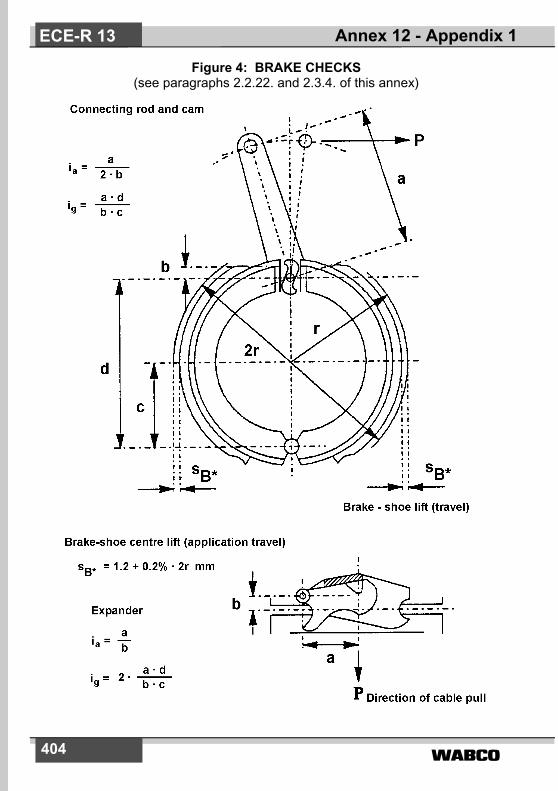
�����404
Figure 4: BRAKE CHECKS(see paragraphs 2.2.22. and 2.3.4. of this annex)
Annex 12 - Appendix 1ECE-R 13

����� 405
Figure 5: MECHANICAL-TRANSMISSION BRAKING SYSTEM (see paragraph 2.3. of this annex)
1.2 Control device 1.3 Transmission 1.4 Brakes
Annex 12 - Appendix 1 ECE-R 13

�����406
Figure 6: MECHANICAL BRAKE(see paragraph 2 of this annex)
Figure 7: HYDRAULIC BRAKE(see paragraph 2 of this annex)
Annex 12 - Appendix 1ECE-R 13

����� 407
Figure 8: HYDRAULIC-TRANSMISSION BRAKING SYSTEM(see paragraph 2 of this annex)
1.2 Control device 1.4 Brakes
Ds� 1�1
s
s�HZ2� 2
sHZ
FHZ
ih =1 - 1�2 - 2�
dc
F RZ
3�3
4�4drum brake
i� =3 - 3�4 - 4�g =d
c
r eff
4�44� 4
3�33� 3
disc brake
i� =3 - 3�4 - 4�g =
reffreff
= 1
4�44� 4
r eff
3� 3
disc brake
i� =3 - 3�
2 (4 - 4��g =reffreff
= 1�
Annex 12 - Appendix 1 ECE-R 13

�����408
Annex 12 - Appendix 2
TEST REPORT ON INERTIA BRAKING SYSTEM CONTROL DEVICE
1. Manufacturer . . . . . . . . . . . . . . . . . . . . . . . . . . . . . . . . . .2. Make . . . . . . . . . . . . . . . . . . . . . . . . . . . . . . . . . . . . . . . .3. Type. . . . . . . . . . . . . . . . . . . . . . . . . . . . . . . . . . . . . . . . . 4. Characteristics of trailers for which control device intended
by manufacturer: . . . . . . . . . . . . . . . . . . . . . . . . . . . . . . .4.1. mass G'A = . . . . . . . . . . . . . . . . . . . . . . . . . . . . . . . . . . . kg4.2. permissible static vertical force at towing-device head . N4.3. trailer with rigid drawbar/multi-axled trailer with pivoted
drawbar 1) 5. Brief description
(List of attached plans and dimensioned drawings)6. Diagram showing principle of control7. Travel s = . . . . . . . . . . . . . . . . . . . . . . . . . . . . . . . . . . . . mm8. Reduction ratio of control device:8.1. with mechanical transmission device 1)
iHO = from . . . . . . . . . . . . . . . to . . . . . . . . . . . . . . . . . . . 2)
8.2. with hydraulic transmission device 1)
ih = from . . . . . . . . . . . . . . . to . . . . . . . . . . . . . . . . . . . . 2)
FHZ = . . . . . . . . . . . . . . . . . . . . . . . . . . . . . . . . . . . . . . . cm2
travel of master cylinder sHZ . . . . . . . . . . . . . . . . . . . . . . mmspare travel of master cylinder s"Hz . . . . . . . . . . . . . . . . mm
9. Test results:9.1. Efficiency
with mechanical transmission device 1) �H = . . . . . . . .
with hydraulic transmission device 1) �H = . . . . . . . . . .9.2. Supplementary force K = . . . . . . . . . . . . . . . . . . . . . . . . N9.3. Maximum compressive force D1 = . . . . . . . . . . . . . . . . . N
Annex 12 - Appendix 2ECE-R 13
1) Strike out what does not apply.2) State lengths whose ratio was used to determine iHO or ih.

����� 409
9.4. Maximum tractive force D2 = . . . . . . . . . . . . . . . . . . . . N9.5. Stress threshold KA = . . . . . . . . . . . . . . . . . . . . . . . . . . N9.6. Loss of travel and spare travel:
where the position of the drawing devicehas an effect so 1) = . . . . . . . . . . . . . . . . . . . . . . . . . . . mmwith a hydraulic-transmission device s" 1) = s"Hz • ih = . . . . . . . . . . . . . . . . . . . . . . . . . . . . . . mm
9.7. Effective (useful) travel of control s' = . . . . . . . . . . . . . . mm9.8. An overload protector according to paragraph 3.6. of this annex is
provided / not provided 1)
9.8.1. If the overload protector is fitted before the transmission lever of thecontrol device
9.8.1.1. Threshold force of the overload protectorDop = . . . . . . . . . . . . . . . . . . . . . . . . . . . . . . . . . . . . . . . N
9.8.1.2. Where the overload protector is mechanical 1)
max. force which the inertia control device can developP'max/iHo = Pop_max = . . . . . . . . . . . . . . . . . . . . . . . . . . N
9.8.1.3. Where the overload protector is hydraulic 1) the pressure which the inertia control device can developp'max/ih = Pop_max = . . . . . . . . . . . . . . . . . . . . . . . . . . . N/cm2
9.8.2. If the overload protector is fitted after the transmission lever of thecontrol device
9.8.2.1. Threshold force of the overload protectorwhere the overload protector is mechanical 1) Dop • iHo = . . . . . . . . . . . . . . . . . . . . . . . . . . . . . . . . . . . N
where the overload protector is hydraulic 1) Dop • ih = . . . . . . . . . . . . . . . . . . . . . . . . . . . . . . . . . . . . N
9.8.2.2. Where the overload protector is mechanical 1)
max force which the inertia control device can developP'max = Pop_max = . . . . . . . . . . . . . . . . . . . . . . . . . . . . . N
9.8.2.3. Where the overload protector is hydraulic 1)
the pressure which the inertia control device can developP'max = Pop_max = . . . . . . . . . . . . . . . . . . . . . . . . . . . . . N/cm2
Annex 12 - Appendix 2 ECE-R 13

�����410
10. The control device described above complies/does not comply 1) with the requirements of paragraphs 3, 4 and 5 of this annex.Date. . . . . . . . . . . . . . . . . . . . . . . . . . . . . . . . . . . . . . . . .Signature . . . . . . . . . . . . . . . . . . . . . . . . . . . . . . . . . . . . .
11. This test has been carried out and the results reported in accordancewith relevant provisions of annex 12 to ECE Regulation No. 13 aslast amended by the .... series of amendments.
Technical Service 3) carrying out the test
Signed: .................................. Date: ..........................................
12. Approval Authority 3)
Signed: .................................. Date: ...........................................
Annex 12 - Appendix 2ECE-R 13
3) To be signed by different persons even when the Technical Service andApproval Authority are the same or alternatively, a separate ApprovalAuthority authorisation issued with the report.

����� 411
Annex 12 - Appendix 3
TEST REPORT ON THE BRAKE1. Manufacturer . . . . . . . . . . . . . . . . . . . . . . . . . . . . . . . . . 2. Make . . . . . . . . . . . . . . . . . . . . . . . . . . . . . . . . . . . . . . . 3. Type . . . . . . . . . . . . . . . . . . . . . . . . . . . . . . . . . . . . . . . . 4. Permissible ’maximum mass’
per wheel GBo = . . . . . . . . . . . . . . . . . . . . . . . . . . . . . . kg5. Braking torque M* (as specified by the manufacturer according
to paragraph 2.2.23. of this annex) = . . . . . . . . . . . . . . Nm6. Dynamic tyre rolling radius
Rmin = . . . . . . . . .m; Rmax = . . . . . . . . . . . . . . . m7. Brief description
(List of plans and dimensioned drawings)8. Diagram showing principle of brake
9. Test result:mechanical brake 1) hydraulic brake 1)
9.1. Reduction ratio 9.1.A. Reduction ratioig = . . . . . . . . . . . . 2) i'g = . . . . . . . . . . . 2)
9.2. Lift (application travel) 9.2.A. Lift (application travel)sB = mm sB = . . . . . . . . . . . mm
9.3. Prescribed lift (prescribed 9.3.A. Prescribed lift (prescribedapplicationtravel) application travel)sB* = . . . . . . . . .mm sB* = . . . . . . . . . . . mm
9.4. Retraction force 9.4.A. Retraction pressurePo = . . . . . . . . . . . N po = . . . . . . . . . . . N/cm2
9.5. Coefficient (characteristic) 9.5.A. Coefficient (characteristic) = . . . . . . . . . . . m ' = . . . . . . . . . . . m
9.6. An overload protector 9.6.A. An overload protectoraccording to paragraph 3.6. according to paragraph of this annex is / is not 3.6. of this annex is / is notprovided 1) provided 1)
Annex 12 - Appendix 3 ECE-R 13
1) Strike out what does not apply.2) State lengths used to determine iHO, ih, iH1.

�����412
9.6.1. Braking torque activating 9.6.1.A. Braking torque activatingthe overload protector the overload protectorMop = . . . . . . . . Nm Mop = . . . . . . . . . . Nm
9.7. Force for M* 9.7.A. Pressure for M*P* = . . . . . . . . . . . .N p* = . . . . . . . . . . . . . N/cm2
9.8.A. Surface area of wheelcylinderFRZ = . . . . . . . . . . . cm2
9.9.A. (for disc brakes)Fluid volume absorptionV60 = . . . . . . . . . . . . cm3
9.10. Service brake performance when the trailer moves rearwards (seefigures 6 and 7 of appendix 1 to this annex)
9.10.1. Maximum Fig 6 braking 9.10.1.A. Maximum Fig 7 braking torque torqueMr = . . . . . . . . . Nm Mr = . . . . . . . . . Nm
9.10.2. Maximum permissible travel 9.10.2.A. Maximum permissible fluidsr = . . . . . . . . . . mm volume absorbed
Vr = . . . . . . . . . . cm³
9.11. Further brake characteristics when the trailer moves rearwards (seefigures 6 and 7 of appendix 1 to this annex)
9.11.1. Brake-retraction force 9.11.1.A. Brake-retraction pressurePor = . . . . . . . . . . .N por = . . . . . . . . . . N/cm2
9.11.2. Brake characteristic 9.11.2.A. Brake characteristicr = m 'r = . . . . . . . . . . m
9.12. Tests according to paragraph 7.5. of this annex (if applicable) (cor-rected to take account of the rolling resistance corresponding to 0.01 • g • GBo)
9.12.1. Brake test Type 0Test speed = ................................... km/hBraking ratio = ..................................... %Control force = ..................................... N
Annex 12 - Appendix 3ECE-R 13

����� 413
9.12.2. Brake test Type ITest speed = ............................................................... km/hSustained braking ratio = ................................................ %Braking time = ............................................................... minutesHot performance = .......................................................... %(expressed as a % of the above Type 0 test result in item 9.12.1.)Control force = ................................................................. N
10. The above brake does / does not 1) conform to the requirements ofparagraphs 3 and 6 of the testing conditions for vehicles fitted withinertia braking systems described in this annex.The brake may / may not 1) be used for an inertia braking systemwithout an overload protector.
Signature . . . . . . . . . . . . . . . . . . . . . . . . . . . . . . . . . . . .
11. This test has been carried out and the results reported in accordancewith relevant provisions of annex 12 to ECE Regulation No. 13 as lastamended by the .... series of amendments.
Technical Service 3) carrying out the test
Signed: ............................... Date: ....................................
12. Approval Authority 3)
Signed: ............................... Date: ....................................
Annex 12 - Appendix 3 ECE-R 13
1) Strike out what does not apply.3) To be signed by different persons even when the Technical Service and
Approval Authority are the same or alternatively, a separate ApprovalAuthority authorisation issued with the report.

�����414
Annex 12 - Appendix 4
TEST REPORT ON THE COMPATIBILITY OF THE INERTIA BRAKE CONTROL DEVICE, THE TRANSMISSION AND
THE BRAKES ON THE TRAILER1. Control device . . . . . . . . . . . . . . . . . . . . . . . . . . . . . . . .
described in the attached test report (see appendix 2 to this annex)Reduction ratio selected:iHO 1) =. . . . . . . . . . 2) or ih 1) =. . . . . . . . . . . 2) (must be within the limits specified in paragraphs 8.1. or 8.2. of appendix 2 to this annex)
2. Brakesdescribed in the attached test report (see appendix 3 to this annex)
3. Transmission devices on the trailer3.1. Brief description with diagram showing principle3.2. Reduction ratio and efficiency of the mechanical-transmission
device on the traileriH1 1) = . . . . . . . . . . . . . . . . . . . . . . . . . . . . . . . . . . . . . . 2)
�H1 1) = . . . . . . . . . . . . . . . . . . . . . . . . . . . . . . . . . . . . . .4. Trailer4.1. Manufacturer . . . . . . . . . . . . . . . . . . . . . . . . . . . . . . . . . 4.2. Make . . . . . . . . . . . . . . . . . . . . . . . . . . . . . . . . . . . . . . . .4.3. Type . . . . . . . . . . . . . . . . . . . . . . . . . . . . . . . . . . . . . . . . 4.4. Type of drawbar connection: trailer with rigid drawbar/
multi-axled trailer with pivoted drawbar 1) 4.5. Number of brakes n = . . . . . . . . . . . . . . . . . . . . . . . . . . . 4.6. Technically permissible maximum mass GA = . . . . . . . . kg4.7. Dynamic tyre rolling radius R = . . . . . . . . . . . . . . . . . . . . m4.8. Permissible thrust on coupling
D* = 0.100 • g • GA 1) = . . . . . . . . . . . . . . . . . . . . . . . . . NorD* = 0.067 • g • GA 1) = . . . . . . . . . . . . . . . . . . . . . . . . . . N
Annex 12 - Appendix 4ECE-R 13
1) Strike out what does not apply.2) State lengths used to determine iHO, ih, iH1.

����� 415
4.9. Required braking force B* = 0.50 • g • GA =. . . . . . . . . . N4.10. Brake force B = 0.49 • g • GA = . . . . . . . . . . . . . . . . . . . N5. Compatibility - Test results5.1. Stress threshold 100 • KA/ (g • GA) = . . . . . . . . . . . . . .
(must be between 2 and 4)5.2. Maximum compressive force 100 • D1/(g • GA) = . . . . . .
(must not exceed 10 for trailers with rigid drawbar or 6.7 for multi-axled trailers with pivoted drawbar)
5.3. Maximum tractive force 100 • D2/ (g • GA) = . . . . . . . . . (must be between 10 and 50)
5.4. Technically permissible maximum mass for inertia control deviceG'A = . . . . . . . . . . . . . . . . . . . . . . . . . . . . . . . . . . . . . . . kg(must not be less than GA)
5.5. Technically permissible maximum mass for all of trailer's brakesGB = n • GBo = . . . . . . . . . . . . . . . . . . . . . . . . . . . . . . . . kg(must not be less than GA)
5.6. Braking torque of the brakesn • M*/ (B • R) = . . . . . . . . . . . . . . . . . . . . . . . . . . . . . . . (must be equal or greater than 1.0)
5.6.1. An overload protector within the meaning of paragraph 3.6. of thisannex is / is not 1) fitted on the inertia control device / on the brakes 1)
5.6.1.1. where the overload protector is mechanical on the inertia controldevice 1)
n • P* / (iH1 • �H1 • P'max) = . . . . . . . . . . . . . . . . . . . . . . (must be equal or greater than 1.2)
5.6.1.2. where the overload protector is hydraulic on the inertia control device 1)
P* / P'max = . . . . . . . . . . . . . . . . . . . . . . . . . . . . . . . . . . (must be equal or greater than 1.2)
5.6.1.3. if the overload protector is on the inertia control device:threshold force Dop / D* = . . . . . . . . . . . . . . . . . . . . . . . (must be equal or greater than 1.2)
5.6.1.4. if the overload protector is fitted on the brake:threshold torque n • Mop / (B • R) = . . . . . . . . . . . . . . . . (must be equal or greater than 1.2)
Annex 12 - Appendix 4 ECE-R 13

�����416
5.7. Inertia braking system with mechanical transmission device 1)
5.7.1. iH = iHO • iH1 = . . . . . . . . . . . . . . . . . . . . . . . . . . . . . . .5.7.2. �H = �HO • �H1 = . . . . . . . . . . . . . . . . . . . . . . . . . . . . . .
5.7.3. ��
(must not be greater than iH)
5.7.4. = .................
(must not be less than iH)5.7.5. Ratio s'/iH = .......................................................................
when the trailer moves rearward . (shall not exceed sr)5.7.6. Braking torque when the trailer moves rearward including rolling
resistance0,08 • g • GA • R = ............................................................ Nm (shall not exceed n • Mr)
5.8. Inertia braking system with hydraulic transmission device 1) 5.8.1. ih/FHZ = . . . . . . . . . . . . . . . . . . . . . . . . . . . . . . . . . . . . . .
5.8.2.
= ...............
(must not be greater than ih/FHZ) 5.8.3.
(must not be less than ih/FHZ)5.8.4. s/ih = . . . . . . . . . . . . . . . . . . . . . . . . . . . . . . . . . . . . . . . .
(must not be greater than travel of master cylinder actuator asspecified in paragraph 8.2. of appendix 2 to this annex)
B R��
--------- n P o+ 1
D✴� K � �H–
--------------------------------
ssB✴ ig�--------------------
B R�n --------- Po+� 1
D✴� K � �H–
--------------------------------
s2sB ✴ n F RZ ig� �------------------------------------------------
Annex 12 - Appendix 4ECE-R 13

����� 417
5.8.5. Ratio s'/FHZ = ......................................................................when the trailer moves rearward (shall not exceed Vr)
5.8.6. Braking torque when the trailer moves rearward including rollingresistance0,08 • g • GA • R = ............................................................... Nm
(shall not exceed n • Mr)
6. The inertia braking system described above complies/does notcomply 1) with the requirements of paragraphs 3 to 9 of this annex.
Date: . . . . . . . . . . . . . . . . . . . . . . . . . . . . . . . . . . . . . . .
Signature: . . . . . . . . . . . . . . . . . . . . . . . . . . . . . . . . . . .
7. This test has been carried out and the results reported in accordancewith relevant provisions of annex 12 to ECE Regulation No. 13 aslast amended by the .... series of amendments.
Technical Service 3) carrying out the test
Signed: .................................. Date: ........................................
8. Approval Authority 3)
Signed: .................................. Date: ........................................
Annex 12 - Appendix 4 ECE-R 13
1) Strike out what does not apply.3) To be signed by different persons even when the Technical Service and
Approval Authority are the same or alternatively, a separate ApprovalAuthority authorisation issued with the report.

�����418
Annex 13
TEST REQUIREMENTS FOR VEHICLES FITTED WITH ANTI-LOCK BRAKING SYSTEMS
1. GENERAL1.1. This annex defines the required braking performances for road
vehicles fitted with anti-lock braking systems. In addition, power-driven vehicles which are authorized to tow a trailer, and trailersequipped with compressed-air braking systems, shall, when thevehicles are laden, meet the requirements for compatibility set out inannex 10 to this Regulation. However, for all load conditions, abraking rate shall be developed between a pressure of 0.2 and 1 baror equivalent digital demand value at the coupling head of the controlline(s).
1.2. The anti-lock braking systems known at present comprise a sensoror sensors, a controller or controllers and a modulator or modulators.Any device of a different design which may be introduced in future, orwhere an anti-lock braking function is integrated into another system,shall be deemed to be an anti-lock braking system within themeaning of this annex and annex 10 to this Regulation, if it providesperformance equal to that prescribed by this annex.
2. DEFINITIONS2.1. An ”anti-lock braking system“ is a part of a service braking system
which automatically controls the degree of slip, in the direction ofrotation of the wheel(s), on one or more wheels of the vehicle duringbraking.
2.2. ”Sensor“ means a component designed to identify and transmit to thecontroller the conditions of rotation of the wheel(s) or the dynamicconditions of the vehicle.
2.3. ”Controller“ means a component designed to evaluate the datatransmitted by the sensor(s) and to transmit a signal to themodulator.
2.4. ”Modulator“ means a component designed to vary the brakingforce(s) in accordance with the signal received from the controller.
2.5. ”Directly controlled wheel“ means a wheel whose braking force ismodulated according to data provided at least by its own sensor. 1)
2.6. ”Indirectly controlled wheel“ means a wheel whose braking force is
Annex 13ECE-R 13
����� 419
modulated according to data provided by the sensor(s) of otherwheel(s).1)
2.7. ”Full cycling“ means that the anti-lock braking system is repeatedlymodulating the brake force to prevent the directly controlled wheelsfrom locking. Brake applications where modulation only occurs onceduring the stop shall not be considered to meet this definition.In the case of trailers with pneumatic braking systems, full cycling ofthe anti-lock braking system is only assured when the pressureavailable at any brake actuator of a directly controlled wheel is morethan 1 bar above the maximum cycling pressure throughout a giventest. The supply pressure available may not be increased above8,0 bar.
3. TYPES OF ANTI-LOCK BRAKING SYSTEMS3.1. A power-driven vehicle is deemed to be equipped with an anti-lock
braking system within the meaning of paragraph 1. of annex 10 to thisRegulation, if one of the following systems is fitted:
3.1.1. Category 1 anti-lock braking system
A vehicle equipped with a category 1 anti-lock braking system shallmeet all the relevant requirements of this annex.
3.1.2. Category 2 anti-lock braking system
A vehicle equipped with a category 2 anti-lock braking system shallmeet all the relevant requirements of this annex, except those ofparagraph 5.3.5.
3.1.3. Category 3 anti-lock braking system
A vehicle equipped with a category 3 anti-lock braking system shallmeet all the relevant requirements of this annex, except those ofparagraphs 5.3.4. and 5.3.5. On such vehicles, any individual axle (orbogie) which does not include at least one directly controlled wheelmust fulfil the conditions of adhesion utilization and the wheel-lockingsequence of annex 10 to this Regulation, with regard to the brakingrate and the load respectively. These requirements may be checkedon high- and low-adhesion road surfaces (about 0.8 and 0.3 maxi-mum) by modulating the service brake control force.
3.2. A trailer is deemed to be equipped with an anti-lock braking systemwithin the meaning of paragraph 1. of annex 10 to this Regulation
Annex 13 ECE-R 13
1) Anti-lock braking systems with select-high control are deemed to includeboth directly and indirectly controlled wheels; in systems with select-low con-trol, all sensed wheels are deemed to be directly controlled wheels.

�����420
when at least two wheels on opposite sides of the vehicle are directlycontrolled and all remaining wheels are either directly or indirectlycontrolled by the anti-lock braking system. In the case of full trailers,at least two wheels on one front axle and two wheels on one rearaxle are directly controlled with each of these axles having at leastone independent modulator and all remaining wheels are eitherdirectly or indirectly controlled. In addition, the anti-lock equippedtrailer shall meet one of the following conditions:
3.2.1 Category A anti-lock braking system
A trailer equipped with a category A anti-lock braking system shallmeet all the relevant requirements of this annex.
3.2.2. Category B anti-lock braking system
A trailer equipped with a category B anti-lock braking system shallmeet all the relevant requirements of this annex, except paragraph6.3.2.
4. GENERAL REQUIREMENTS4.1. Any electrical failure or sensor anomaly that affects the system with
respect to the functional and performance requirements in thisannex, including those in the supply of electricity, the external wiringto the controller(s), the controller(s) 2) and the modulator(s) shall besignalled to the driver by a specific optical warning signal. The yellowwarning signal specified in paragraph 5.2.1.29.1.2. shall be used forthis purpose.
4.1.1. Sensor anomalies, which cannot be deleted under static conditions,shall be detected not later than when the vehicle speed exceed 10km/h. 3) However, to prevent erroneous fault indication when asensor is not generating a vehicle speed output, due to non-rotationof a wheel, verification may be delayed but detected not later thanwhen the vehicle speed exceeds 15 km/h.
4.1.2. When the anti-lock braking system is energized with the vehiclestationary, electrically controlled pneumatic modulator valve(s) shallcycle at least once.
Annex 13ECE-R 13
2) The manufacturer shall provide the Technical Service with documentationrelating to the controller(s) which follows the format set out in annex 18.
3) The warning signal may light up again while the vehicle is stationary, pro-vided that it is extinguished before the vehicle speed reaches 10 km/h or 15km/h, as appropriate, when no defect is present.

����� 421
4.2. Power-driven vehicles equipped with an anti-lock braking system andauthorized to tow a trailer equipped with such a system, with theexception of vehicles of categories M1 and N1, shall be fitted with aseparate optical warning signal for the anti-lock braking system of thetrailer, meeting the requirements of paragraph 4.1. of this annex. Theseparate yellow warning signals specified in paragraph 5.2.1.29.2.shall be used for this purpose, activated via pin 5 of the electricalconnector conforming to ISO 7638:1997 *).
4.3. In the event of a failure in the anti-lock braking system, the residualbraking performance shall be that prescribed for the vehicle inquestion in the event of a failure of part of the transmission of theservice braking system (see paragraph 5.2.1.4. of this Regulation).This requirement shall not be construed as a departure from therequirements concerning secondary braking. In the case of trailersthe residual braking performance in the event of a defect in the anti-lock braking system according to paragraph 4.1. shall be at least 80per cent of the prescribed laden performance for the service brakingsystem of the relevant trailer.
4.4. The operation of the anti-lock braking system shall not be adverselyaffected by magnetic or electrical fields. This shall be demonstratedby compliance with Regulation No. 10, 02 series of amendments 4).
4.5 A manual device may not be provided to disconnect or change thecontrol mode 5) of the anti-lock braking system, except on off-roadpower-driven vehicles of categories N2 and N3 as defined in annex 7to the Consolidated Resolution on the Construction of Vehicles(R.E.3); where a divice is fitted to N2 or N3 category vehicles, thefollowing conditions must be met:
4.5.1. the power-driven vehicle with the anti-lock braking system discon-nected or the control mode changed by the device referred to inparagraph 4.5. above must satisfy all the relevant requirements inannex 10 to this Regulation;
Annex 13 ECE-R 13
4) This must be confirmed by the technical requirements of Directive 72/245/EEC, as revised by Directive 95/54/EC.
5) It is understood that devices changing the control mode of the anti-lock brak-ing system are not subject to paragraph 4.5. of this annex if in the changedcontrol mode condition all requirements for the category of anti-lock brakingsystems, with which the vehicle is equipped, are fulfilled. However, in thiscase, paragraphs 4.5.2., 4.5.3. and 4.5.4. of this annex shall be met.
*) The ISO 7638:1997 connector may be used for 5 pin or 7 pin applications, asappropriate.

�����422
4.5.2. an optical warning signal shall inform the driver that the anti-lockbraking system has been disconnected or the control mode changed;the yellow anti-lock failure warning signal specified in paragraph5.2.1.29.1.2. may be used for this purpose. The warning signal maybe constant or flashing.
4.5.3. the anti-lock braking system must automatically be reconnected/returned to on-road when the ignition (start) device is again set to the”on“ (run) position;
4.5.4. the vehicle user’s handbook provided by the manufacturer shouldwarn the driver of the consequences of manual disconnection ormode change of the anti-lock braking system;
4.5.5. the device referred to in paragraph 4.5. above may, in conjunctionwith the towing vehicle, disconnect/change the control mode of theanti-lock braking system of the trailer. A separate device for the traileralone is not permitted.
4.6. Vehicles equipped with an integrated endurance braking systemmust also be equipped with an anti-lock braking system acting atleast on the service brakes of the endurance braking system’scontrolled axle and on the endurance braking system itself, and shallfulfil the relevant requirements of this annex.
5. SPECIAL PROVISIONS CONCERNING POWER-DRIVEN VEHICLES
5.1. ENERGY CONSUMPTIONPower-driven vehicles equipped with anti-lock braking systems mustmaintain their performance when the service braking control device isfully applied for long periods. Compliance with this requirement shallbe verified by means of the following tests:
5.1.1. Test procedure5.1.1.1. The initial energy level in the energy storage device(s) shall be that
specified by the manufacturer. This level shall be at least such as toensure the efficiency prescribed for service braking when the vehicleis laden. The energy storage device(s) for pneumatic auxiliaryequipment must be isolated.
5.1.1.2. From an initial speed of not less than 50 km/h, on a surface with acoefficient of adhesion of 0.3 6) or less, the brakes of the laden
Annex 13ECE-R 13
6) Until such test surfaces become generally available, tyres at the limit ofwear, and higher values up to 0.4 may be used at the discretion of the Tech-nical Service. The actual value obtained and the type of tyres and surfaceshall be recorded.
����� 423
vehicle shall be fully applied for a time t, during which time the energyconsumed by the indirectly controlled wheels shall be taken intoconsideration and all directly controlled wheels must remain undercontrol of the anti-lock braking system.
5.1.1.3. The vehicle's engine shall then be stopped or the supply to theenergy transmission storage device(s) cut off.
5.1.1.4. The service braking control device shall then be fully actuated fourtimes in succession with the vehicle stationary.
5.1.1.5. When the control device is applied for the fifth time, it must bepossible to brake the vehicle with at least the performanceprescribed for secondary braking of the laden vehicle.
5.1.1.6. During the tests, in the case of a power-driven vehicle authorized todraw a trailer equipped with a compressed-air braking system, thesupply line shall be stopped and an energy storage device of 0.5 litrecapacity shall be connected to the pneumatic control line - if fitted -(in accordance with paragraph 1.2.2.3. of annex 7A to thisRegulation). When the brakes are applied for the fifth time, asprovided in paragraph 5.1.1.5. above, the energy level supplied to thepneumatic control line shall not be below half the level obtained at afull application starting with the initial energy level.
5.1.2. Additional requirements5.1.2.1. The coefficient of adhesion of the road surface shall be measured
with the vehicle under test, by the method described in paragraph1.1. of appendix 2 to this annex.
5.1.2.2. The braking test shall be conducted with the engine disconnectedand idling, and with the vehicle laden.
5.1.2.3. The braking time t shall be determined by the formula:
t = ( but not less than 15 seconds )
where t is expressed in seconds and vmax represents the maximumdesign speed of the vehicle expressed in km/h, with an upper limit of160 km/h.
5.1.2.4. If the time t cannot be completed in a single braking phase, furtherphases may be used, up to a maximum of four in all.
5.1.2.5. If the test is conducted in several phases, no fresh energy shall besupplied between the phases of the test.From the second phase, the energy consumption corresponding tothe initial brake application may be taken into account, by subtracting
vmax7
-------------
Annex 13 ECE-R 13

�����424
one full brake application from the four full applications prescribed inparagraph 5.1.1.4. (and 5.1.1.5., 5.1.1.6. and 5.1.2.6.) of this annexfor each of the second, third and fourth phases used in the testprescribed in paragraph 5.1.1. of this annex as applicable.
5.1.2.6. The performance prescribed in paragraph 5.1.1.5. of this annex shallbe deemed to be satisfied if, at the end of the fourth application, withthe vehicle stationary, the energy level in the storage device(s) is ator above that required for secondary braking with the laden vehicle.
5.2. UTILIZATION OF ADHESION5.2.1. The utilization of adhesion by the anti-lock braking system takes into
account the actual increase in braking distance beyond thetheoretical minimum. The anti-lock braking system shall be deemedto be satisfactory when the condition � � 0.75 is satisfied, where� represents the adhesion utilized, as defined in paragraph 1.2. ofappendix 2 to this annex.
5.2.2. The adhesion utilization � shall be measured on road surfaces with acoefficient of adhesion of 0.3 6) or less, and of about 0.8 (dry road),with an initial speed of 50 km/h. To eliminate the effects of differentialbrake temperatures it is recommended that zAL be determined priorto the determination of k.
5.2.3. The test procedure to determine the coefficient of adhesion (k) andthe formulae for calculation of the adhesion utilization (�) shall bethose laid down in appendix 2 to this annex.
5.2.4. The utilization of adhesion by the anti-lock braking system shall bechecked on complete vehicles equipped with anti-lock brakingsystems of categories 1 or 2. In the case of vehicles equipped withcategory 3 anti-lock braking systems, only the axle(s) with at leastone directly controlled wheel must satisfy this requirement.
5.2.5. The condition � � 0.75 shall be checked with the vehicle laden andunladen. 7) The laden test on the high adhesion surface may beomitted if the prescribed force on the control device does not achievefull cycling of the anti-lock braking system. For the unladen test, the
Annex 13ECE-R 13
7) Until a uniform test procedure is established, the tests required by this para-graph may have to be repeated for vehicles equipped with electrical regener-ative braking systems, in order to determine the effect of different brakingdistribution values provided by automatic functions on the vehicle.
8) ”Full force“ means the maximum force laid down in annex 4 to this Regula-tion for the category of vehicle; a higher force may be used if required to acti-vate the anti-lock braking system.
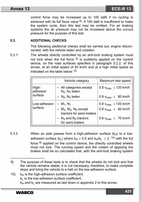
����� 425
control force may be increased up to 100 daN if no cycling isachieved with its full force value 8). If 100 daN is insufficient to makethe system cycle, then this test may be omitted. For air brakingsystems the air pressure may not be increased above the cut-outpressure for the purpose of this test.
5.3. ADDITIONAL CHECKSThe following additional checks shall be carried out, engine discon-nected, with the vehicle laden and unladen:
5.3.1. The wheels directly controlled by an anti-lock braking system mustnot lock when the full force 8) is suddenly applied on the controldevice, on the road surfaces specified in paragraph 5.2.2. of thisannex, at an initial speed of 40 km/h and at a high initial speed asindicated on the table below: 9)
5.3.2. When an axle passes from a high-adhesion surface (kH) to a low-adhesion surface (kL) where kH � 0.5 and kH/kL � 2, 10) with the fullforce 8) applied on the control device, the directly controlled wheelsmust not lock. The running speed and the instant of applying thebrakes shall be so calculated that, with the anti-lock braking system
Vehicle category Maximum test speed
High-adhesionsurface
– All categories exceptN2, N3 laden
– N2, N3 laden
0.8 vmax � 120 km/h
0.8 vmax � 80 km/h
Low-adhesionsurface
– M1, N1
– M2, M3, N2 excepttractors for semi-trailers
– N3 and N2 tractorsfor semi-trailers
0.8 vmax � 120 km/h0.8 vmax � 80 km/h
0.8 vmax � 70 km/h
Annex 13 ECE-R 13
9) The purpose of these tests is to check that the wheels do not lock and thatthe vehicle remains stable; it is not necessary, therefore, to make completestops and bring the vehicle to a halt on the low-adhesion surface.
10) kH is the high-adhesion surface coefficient.kL is the low-adhesion surface coefficient.kH and kL are measured as laid down in appendix 2 to this annex.

�����426
fully cycling on the high-adhesion surface, the passage from onesurface to the other is made at high and at low speed, under theconditions laid down in paragraph 5.3.1. of this annex 9).
5.3.3. When a vehicle passes from a low-adhesion surface (kL) to a high-adhesion surface (kH) where kH � 0.5 and kH/kL � 2, 10) with the fullforce 8) applied on the control device, the deceleration of the vehiclemust rise to the appropriate high value within a reasonable time andthe vehicle must not deviate from its initial course. The running speedand the instant of applying the brakes shall be so calculated that, withthe anti-lock braking system fully cycling on the low-adhesionsurface, the passage from one surface to the other occurs atapproximately 50 km/h.
5.3.4. In the case of vehicles equipped with anti-lock braking systems ofcategories 1 or 2, when the right and left wheels of the vehicle aresituated on surfaces with differing coefficients of adhesion (kH andkL), where kH � 0.5 and kH/kL � 2, 10) the directly controlled wheelsmust not lock when the full force 8) is suddenly applied on the controldevice at a speed of 50 km/h.
5.3.5. Furthermore, laden vehicles equipped with anti-lock braking systemsof category 1 shall, under the conditions of paragraph 5.3.4. of thisannex satisfy the prescribed braking rate in appendix 3 to this annex.
5.3.6. However, in the tests provided in paragraphs 5.3.1., 5.3.2., 5.3.3.,5.3.4. and 5.3.5 of this annex, brief periods of wheel-locking shall beallowed. Furthermore, wheel-locking is permitted when the vehiclespeed is less than 15 km/h; likewise, locking of indirectly controlledwheels is permitted at any speed, but stability and steerability mustnot be affected.
5.3.7. During the tests provided in paragraphs 5.3.4. and 5.3.5. of thisannex, steering correction is permitted, if the angular rotation of thesteering control is within 120° during the initial two seconds, and notmore than 240° in all. Furthermore, at the beginning of these teststhe longitudinal median plane of the vehicle must pass over theboundary between the high- and low-adhesion surfaces and duringthese tests no part of the (outer) tyres must cross this boundary. 7)
6. SPECIAL PROVISIONS CONCERNING TRAILERS6.1. ENERGY CONSUMPTION
Trailers equipped with anti-lock braking systems shall be so designedthat, even after the service braking control device has been fully app-
Annex 13ECE-R 13

����� 427
lied for some time, the vehicle retains sufficient energy to bring it to ahalt within a reasonable distance.
6.1.1. Compliance with the above requirement shall be checked by theprocedure specified below, with the vehicle unladen, on a straightand level road with a surface having a good coefficient of adhesion11) and with the brakes adjusted as closely as possible and with theproportioning/load-sensing valve (if fitted) held in the ”laden“ positionthroughout the test.
6.1.2. In the case of compressed air braking systems, the initial energy levelin the energy transmission storage device(s) shall be equivalent to apressure of 8.0 bar at the coupling head of the trailer's supply line.
6.1.3. With an initial vehicle speed of at least 30 km/h the brakes shall befully applied for a time t = 15 s, during which all wheels shall remainunder control of the anti-lock braking system. During this test, thesupply to the energy transmission storage device(s) shall be cut off.
If the time t = 15 s cannot be completed in a single braking phase, fur-ther phases may be used. During these phases no fresh energy shallbe supplied to the energy transmission storage device(s) and, as fromsecond phase, the additional energy consumption for filling the actua-tors is to be taken into account, e.g. by the following test procedure.
The pressure in the reservoir(s) when starting the first phase is to bethat stated in paragraph 6.1.2. of this annex. At the beginning of thefollowing phase(s) the pressure in the reservoir(s) after application ofthe brakes must be not less than the pressure in the reservoir(s) atthe end of the preceding phase.
At the subsequent phase(s), the only time to be taken into account isfrom the point at which the pressure in the reservoir(s) is equal to thatat the end of the preceding phase.
6.1.4. At the end of the braking, with the vehicle stationary, the servicebraking control device shall be fully actuated four times. During thefifth application, the pressure in the operating circuit must besufficient to provide a total braking force at the periphery of thewheels equal to not less than 22.5 per cent of the maximumstationary wheel load and without causing an automatic application ofany braking system not being under the control of the anti-lockbraking system.
Annex 13 ECE-R 13
11) If the coefficient of adhesion of the test track is too high, preventing the anti-lock braking system from cycling, then the test may be carried out on a sur-face with a lower coefficient of adhesion.

�����428
6.2. UTILIZATION OF ADHESION6.2.1. Braking systems equipped with an anti-lock braking system shall be
deemed acceptable when the condition � � 0.75 is satisfied, where �represents the adhesion utilized, as defined in paragraph 2. ofappendix 2 to this annex. This condition shall be verified with thevehicle unladen, on a straight and level road with a surface having agood coefficient of adhesion. 11) 12)
6.2.2. To eliminate the effects of differential brake temperatures, it isrecommended to determine zRAL prior to the determination of kR.
6.3. ADDITIONAL CHECKS6.3.1. At speeds exceeding 15 km/h, the wheels directly controlled by an
anti-lock braking system must not lock when the full force 8) issuddenly applied on the control device of the towing vehicle. Thisshall be checked, under the conditions prescribed in paragraph 6.2.of this annex, at initial speed of 40 km/h and 80 km/h.
6.3.2. The provisions of this paragraph shall only apply to trailers equippedwith an anti-lock braking system of category A. When the right andleft wheels are situated on surfaces which produce differingmaximum braking rates (zRALH and zRALL), where
� 0.5 and � 2
the directly controlled wheels must not lock when the full force 8) issuddenly applied on the control device of the towing vehicle at aspeed of 50 km/h. The ratio zRALH / zRALL may be ascertained by theprocedure in paragraph 2 of appendix 2 of this annex or by calcula-ting the ratio zRALH / zRALL. Under this condition the unladen vehicleshall satisfy the prescribed braking rate in appendix 3 to thisannex. 12)
6.3.3. At vehicle speed � 15 km/h the directly controlled wheels arepermitted to lock for brief periods, but at speeds < 15 km/h anylocking is permissible. Indirectly controlled wheels are permitted tolock at any speed but in all cases stability must not be affected.
zRALH�H
------------------zRALHzRALL------------------
Annex 13ECE-R 13
12) In the case of trailers fitted with a load-sensing device, the pressure settingmay be increased to ensure full cycling.

����� 429
Annex 13 - Appendix 1
SYMBOLS AND DEFINITIONS
TABLE: SYMBOLS AND DEFINITIONS
SYMBOL NOTES
E wheelbase
ER distance between king-pin and centre of axle or axles of semi-trailer(or distance between drawbar coupling and centre of axle or axles of centre-axle trailer)
� the adhesion utilized of the vehicle: quotient of the maximum brakingrate with the anti-lock braking system operative (zAL) and the coefficient of adhesion (k)
�i the �-value measured on axle i (in the case of a power-driven vehiclewith a category 3 anti-lock braking system)
�H the �-value on the high-adhesion surface
�L the �-value on the low-adhesion surface
F force [N]
FbR braking force of the trailer with the anti-lock braking systeminoperative
FbRmax maximum value of FbR
FbRmaxi value of FbRmax with only axle i of the trailer braked
FbRAL braking force of the trailer with the anti-lock braking system operative
FCnd total normal reaction of road surface on the unbraked and non-drivenaxles of the vehicle combination under static conditions
FCd total normal reaction of road surface on the unbraked and driven axles of the vehicle combination under static conditions
Fdyn normal reaction of road surface under dynamic conditions with the anti-lock braking system operative
Annex 13 - Appendix 1 ECE-R 13
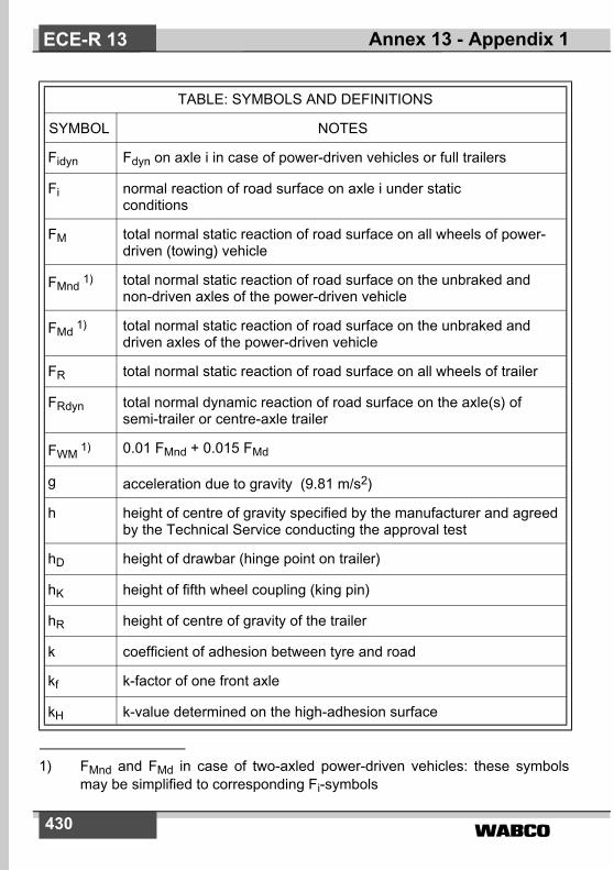
�����430
TABLE: SYMBOLS AND DEFINITIONS
SYMBOL NOTES
Fidyn Fdyn on axle i in case of power-driven vehicles or full trailers
Fi normal reaction of road surface on axle i under staticconditions
FM total normal static reaction of road surface on all wheels of power-driven (towing) vehicle
FMnd�1) total normal static reaction of road surface on the unbraked and non-driven axles of the power-driven vehicle
FMd�1) total normal static reaction of road surface on the unbraked and driven axles of the power-driven vehicle
FR total normal static reaction of road surface on all wheels of trailer
FRdyn total normal dynamic reaction of road surface on the axle(s) of semi-trailer or centre-axle trailer
FWM 1) 0.01 FMnd + 0.015 FMd
g acceleration due to gravity (9.81 m/s2)
h height of centre of gravity specified by the manufacturer and agreedby the Technical Service conducting the approval test
hD height of drawbar (hinge point on trailer)
hK height of fifth wheel coupling (king pin)
hR height of centre of gravity of the trailer
k coefficient of adhesion between tyre and road
kf k-factor of one front axle
kH k-value determined on the high-adhesion surface
Annex 13 - Appendix 1ECE-R 13
1) FMnd and FMd in case of two-axled power-driven vehicles: these symbolsmay be simplified to corresponding Fi-symbols

����� 431
TABLE: SYMBOLS AND DEFINITIONS
SYMBOL NOTES
ki k-value determined on axle i for a vehicle with a category 3 anti-lock braking system
kL k-value determined on the low-adhesion surface
klock value of adhesion for 100% slip
kM k-factor of the power-driven vehicle
kpeak maximum value of the curve "adhesion versus slip"
kr k-factor of one rear axle
kR k-factor of the trailer
P mass of individual vehicle [kg]
R ratio of kpeak to klock
t time interval [s]
tm mean value of t
tmin minimum value of t
z braking rate
zAL braking rate z of the vehicle with the anti-lock braking system operative
zC braking rate z of the vehicle combination, with the trailer only braked and the anti-lock braking system inoperative
zCAL braking rate z of the vehicle combination, with the trailer only braked and the anti-lock braking system operative
zCmax maximum value of zC
zCmax i maximum value of zC with only axle i of the trailer braked
Annex 13 - Appendix 1 ECE-R 13

�����432
TABLE: SYMBOLS AND DEFINITIONS
SYMBOL NOTES
zm mean braking rate
zmax maximum value of z
zMALS zAL of the power-driven vehicle on a "split surface"
zR braking rate z of the trailer with the anti-lock braking system inoperative
zRAL zAL of the trailer obtained by braking all the axles, the towing vehicle unbraked and its engine disengaged
zRALH zRAL on the surface with the high coefficient of adhesion
zRALL zRAL on the surface with the low coefficient of adhesion
zRALS zRAL on the split-surface
zRH zR on the surface with the high coefficient of adhesion
zRL zR on the surface with the low coefficient of adhesion
zRHmax maximum value of zRH
zRLmax maximum value of zRL
zRmax maximum value of zR
Annex 13 - Appendix 1ECE-R 13

����� 433
Annex 13 - Appendix 2
UTILIZATION OF ADHESION
1. METHOD OF MEASUREMENT FOR POWER-DRIVENVEHICLES
1.1. DETERMINATION OF THE COEFFICIENT OF ADHESION (k)1.1.1. The coefficient of adhesion (k) shall be determined as the quotient of
the maximum braking forces without locking the wheels and thecorresponding dynamic load on the axle being braked.
1.1.2. The brakes shall be applied on only one axle of the vehicle undertest, at an initial speed of 50 km/h. The braking forces shall bedistributed between the wheels of the axle to reach maximumperformance. The anti-lock braking system shall be disconnected, orinoperative, between 40 km/h and 20 km/h.
1.1.3. A number of tests at increments of line pressure shall be carried outto determine the maximum braking rate of the vehicle (zmax). Duringeach test, a constant input force shall be maintained and the brakingrate will be determined by reference to the time taken (t) for thespeed to reduce from 40 km/h to 20 km/h using the formula:
z =
zmax is the maximum value of z; t is in seconds.1.1.3.1. Wheel lock may occur below 20 km/h1.1.3.2. Starting from the minimum measured value of t, called tmin, then
select three values of t comprised within tmin and 1.05 tmin andcalculate their arithmetical mean value tm, then calculate
zm =
If it is demonstrated that for practical reasons the three values definedabove cannot be obtained, then the minimum time tmin may be utilized.However, the requirements of paragraph 1.3. below shall still apply.
1.1.4. The braking forces shall be calculated from the measured brakingrate and the rolling resistance of the unbraked axle(s) which is equalto 0.015 and 0.010 of the static axle load for a driven axle and a non-driven axle, respectively.
0 566,t
----------------
0 566,mt
----------------
Annex 13 - Appendix 2 ECE-R 13
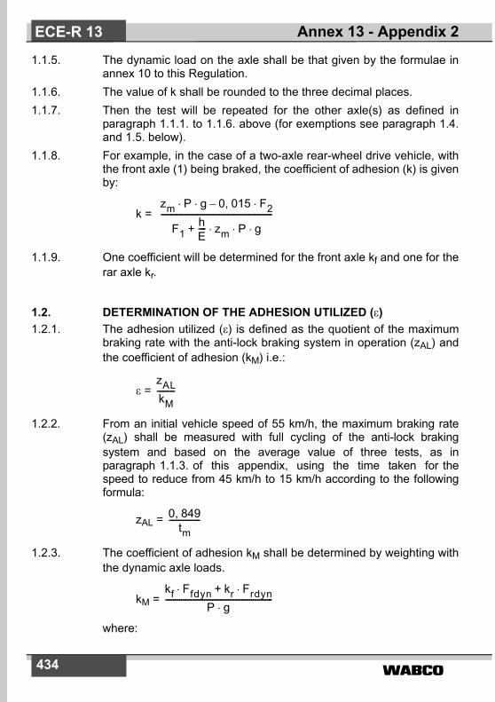
�����434
1.1.5. The dynamic load on the axle shall be that given by the formulae inannex 10 to this Regulation.
1.1.6. The value of k shall be rounded to the three decimal places.1.1.7. Then the test will be repeated for the other axle(s) as defined in
paragraph 1.1.1. to 1.1.6. above (for exemptions see paragraph 1.4.and 1.5. below).
1.1.8. For example, in the case of a two-axle rear-wheel drive vehicle, withthe front axle (1) being braked, the coefficient of adhesion (k) is givenby:
k =
1.1.9. One coefficient will be determined for the front axle kf and one for therar axle kr.
1.2. DETERMINATION OF THE ADHESION UTILIZED (�)1.2.1. The adhesion utilized (�) is defined as the quotient of the maximum
braking rate with the anti-lock braking system in operation (zAL) andthe coefficient of adhesion (kM) i.e.:
� =
1.2.2. From an initial vehicle speed of 55 km/h, the maximum braking rate(zAL) shall be measured with full cycling of the anti-lock brakingsystem and based on the average value of three tests, as inparagraph 1.1.3. of this appendix, using the time taken for thespeed to reduce from 45 km/h to 15 km/h according to the followingformula:
zAL =
1.2.3. The coefficient of adhesion kM shall be determined by weighting withthe dynamic axle loads.
kM =
where:
zm P g 0 015, F2�–� �
F1hE---- zm P g� � �+
---------------------------------------------------------
zALkM---------
0 849,tm
----------------
kf Ffdyn kr Frdyn�+�
P g�-------------------------------------------------------
Annex 13 - Appendix 2ECE-R 13

����� 435
Ffdyn = Ff + · zAL · P · g
Frdyn = Fr - · zAL · P · g
1.2.4. The value of � shall be rounded to two decimal places.1.2.5. In the case of a vehicle equipped with an anti-lock braking system of
categories 1 or 2, the value of zAL will be based on the whole vehicle,with the anti-lock braking system operative, and the adhesion utilized(�) is given by the same formula quoted in paragraph 1.2.1. of thisappendix.
1.2.6. In the case of a vehicle equipped with an anti-lock braking system ofcategory 3, the value of zAL will be measured on each axle which hasat least one directly controlled wheel. For example, for a two-axlerear-wheel drive vehicle with an anti-lock braking system acting onlyon the rear axle (2), the adhesion utilized (�) is given by:
�2 =
This calculation shall be made for each axle having at least onedirectly controlled wheel.
1.3. If � >1.00 the measurements of coefficients of adhesion shall berepeated. A tolerance of 10% is accepted.
1.4. For power-driven vehicles equipped with three axles, only the axlenot associated with a close-coupled bogie will be used to establish ak value for the vehicle. 13)
1.5. For vehicles of categories N2 and N3 with a wheelbase less than3.80 m and with h/E ��0.25 the determination of the coefficient ofadhesion for the rear axle will be omitted.
1.5.1. In the case the adhesion utilized (�) is defined as the quotient of themaximum braking rate with the anti-lock braking system operative(zAL) and the coefficient of adhesion (kf) i.e.
� =
hE----
hE----
zAL P g 0 010, F1�–� �
k2 F2hE---- zAL P g� � �–� �
� �------------------------------------------------------------
zALkf
---------
Annex 13 - Appendix 2 ECE-R 13
13) Until a uniform test procedure is agreed, vehicles with more than three axlesand special vehicles will be subject to consultation with the Technical Service.

�����436
2. METHOD OF MEASUREMENT FOR TRAILERS
2.1. GENERAL2.1.1. The coefficient of adhesion (k) shall be determined as the quotient of
the maximum braking forces without locking the wheels and thecorresponding dynamic load on the axle being braked.
2.1.2. The brakes shall be applied on only one axle of the trailer under test,at an initial speed of 50 km/h. The braking forces shall be distributedbetween the wheels of the axle to reach maximum performance. Theanti-lock braking system shall be disconnected or inoperative,between 40 km/h and 20 km/h.
2.1.3. A number of tests at increments of line pressure shall be carried outto determine the maximum braking rate of the vehicle combination(zCmax) with the trailer only braked. During each test, a constant inputforce shall be maintained and the braking rate will be determined byreference to the time taken (t) for the speed to reduce from 40 km/hto 20 km/h using the formula:
zC =
2.1.3.1. Wheel lock may occur below 20 km/h.2.1.3.2. Starting from the minimum measured value of t, called tmin, then
select three values of t comprised within tmin and 1.05 tmin andcalculate their arithmetical mean value tm, then calculate
zCmax =
If it is demonstrated that for practical reasons the three values defi-ned above cannot be obtained, then the minimum time tmin may beutilized.
2.1.4. The adhesion utilized (�) shall be calculated by means of the formula:
� =
The k value has to be determined according to paragraph 2.2.3. ofthis appendix for full trailers or paragraph 2.3.1. of this appendix forsemi-trailers respectively.
2.1.5. If � > 1.00 the measurements of coefficients of adhesion shall berepeated. A tolerance of 10 % is accepted.
0 566,t
----------------
0 566,tm
----------------
zRALkR
--------------
Annex 13 - Appendix 2ECE-R 13

����� 437
2.1.6. The maximum braking rate (zAL) shall be measured with full cyclingof the anti-lock braking system and the towing vehicle unbraked,based on the average value of three tests, as in paragraph 2.1.3. ofthis appendix.
2.2. FULL TRAILERS2.2.1. The measurement of k (with the anti-lock braking system being
disconnected, or inoperative, between 40 km/h and 20 km/h) will beperformed for the front and rear axles.For one front axle i:
FbRmaxi = zCmaxi (FM + FR) - 0.01FCnd - 0.015FCd
Fi dyn = Fi +
kf =
For one rear axle i:
FbRmaxi = zCmaxi (FM + FR) - 0.01FCnd - 0.015FCd
Fi dyn = Fi -
kr =
2.2.2. The values of kf and kr will be rounded to three decimal places.
2.2.3. The coefficient of adhesion kR shall be determined proportionallyaccording to the dynamic axle loads.
kR =
2.2.4. Measurement of zRAL (with the anti-lock braking system operative)
zCmaxi FM� hD� g P hR � FWM hD�–� �+E
----------------------------------------------------------------------------------------------------
FbRmaxiFidyn
--------------------
zCmaxi FM� hD� g P hR � FWM hD�–� �+E
----------------------------------------------------------------------------------------------------
FbRmaxiFidyn
--------------------
kf Ffdyn kr Frdyn�+�
P g�--------------------------------------------------
Annex 13 - Appendix 2 ECE-R 13
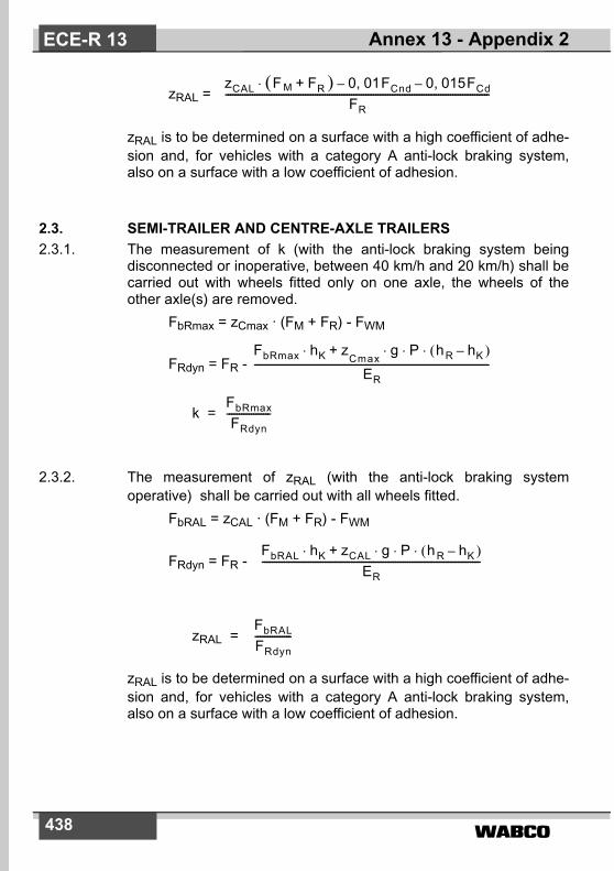
�����438
zRAL =
zRAL is to be determined on a surface with a high coefficient of adhe-sion and, for vehicles with a category A anti-lock braking system,also on a surface with a low coefficient of adhesion.
2.3. SEMI-TRAILER AND CENTRE-AXLE TRAILERS2.3.1. The measurement of k (with the anti-lock braking system being
disconnected or inoperative, between 40 km/h and 20 km/h) shall becarried out with wheels fitted only on one axle, the wheels of theother axle(s) are removed.
FbRmax = zCmax · (FM + FR) - FWM
FRdyn = FR -
k =
2.3.2. The measurement of zRAL (with the anti-lock braking systemoperative) shall be carried out with all wheels fitted.
FbRAL = zCAL · (FM + FR) - FWM
FRdyn = FR -
zRAL =
zRAL is to be determined on a surface with a high coefficient of adhe-sion and, for vehicles with a category A anti-lock braking system,also on a surface with a low coefficient of adhesion.
zCAL F� M FR � 0 01F, Cnd 0 015F, Cd––+�
FR-------------------------------------------------------------------------------------------------------------
FbRmax hK zCmax
g P h� R hK �–� � �+�
ER-------------------------------------------------------------------------------------------------
FbRmaxFRdyn
------------------
FbRAL hK zCAL g P h� R hK �–� � �+�
ER------------------------------------------------------------------------------------------
FbRALFRdyn---------------
Annex 13 - Appendix 2ECE-R 13
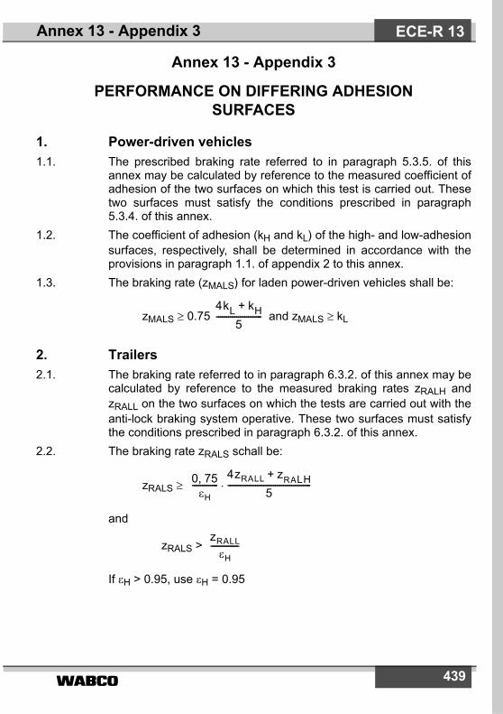
����� 439
Annex 13 - Appendix 3
PERFORMANCE ON DIFFERING ADHESION SURFACES
1. Power-driven vehicles1.1. The prescribed braking rate referred to in paragraph 5.3.5. of this
annex may be calculated by reference to the measured coefficient ofadhesion of the two surfaces on which this test is carried out. Thesetwo surfaces must satisfy the conditions prescribed in paragraph5.3.4. of this annex.
1.2. The coefficient of adhesion (kH and kL) of the high- and low-adhesionsurfaces, respectively, shall be determined in accordance with theprovisions in paragraph 1.1. of appendix 2 to this annex.
1.3. The braking rate (zMALS) for laden power-driven vehicles shall be:
zMALS � 0.75 and zMALS � kL
2. Trailers2.1. The braking rate referred to in paragraph 6.3.2. of this annex may be
calculated by reference to the measured braking rates zRALH andzRALL on the two surfaces on which the tests are carried out with theanti-lock braking system operative. These two surfaces must satisfythe conditions prescribed in paragraph 6.3.2. of this annex.
2.2. The braking rate zRALS schall be:
zRALS �
and
zRALS >
If �H > 0.95, use �H = 0.95
4kL kH+5
-----------------------
0 75,�H
-------------4zRALL zRALH+
5------------------------------------------�
zRALL�H
--------------
Annex 13 - Appendix 3 ECE-R 13

�����440
Annex 13 - Appendix 4
METHOD OF SELECTION OF THE LOW-ADHESION SURFACES
1. Details of the coefficient of adhesion of the surface selected, as inparagraph 5.1.1.2. of this annex, must be given to the TechnicalService.
1.1. These data must include a curve of the coefficient of adhesion versusslip (from 0 to 100 per cent slip) for a speed of approximately 40 km/h. 14)
1.1.1. The maximum value of the curve will represent kpeak and the value at100 per cent slip will represent klock.
1.1.2. The ratio R shall be determined as the quotient of the kpeak and klock.
R =
1.1.3. The value of R shall be rounded to one decimal place.
1.1.4. The surface to be used must have a ratio R between 1.0 and 2.0. 15)
kpeakklock-------------
Annex 13 - Appendix 4ECE-R 13
14) Until a uniform test procedure is established for the determination of theadhesion curve for vehicles with a maximum mass exceeding 3.5 tonnes,the curve established for passenger cars may be used. In this case, for suchvehicles, the ratio kpeak to klock shall be established using a value of kpeak asdefined in appendix 2 to this annex. With the consent of the Technical Serv-ice, the coefficient of adhesion described in this paragraph may be deter-mined by another method provided that the equivalence of the values ofkpeak and klock are demonstrated.
15) Until such test surfaces become generally available, a ratio R up to 2.5 isacceptable, subject to discussion with the Technical Service.

����� 441
2. Prior to the tests, the Technical Service shall ensure that the selectedsurface meets the specified requirements and shall be informed ofthe following:(a) test method to determine R,(b) type of vehicle (power-driven vehicle, trailer ...),(c) axle load and tyres (different loads and different tyres have
to be tested and the results shown to the Technical Servicewhich will decide if they are representative for the vehicleto be approved).
2.1 The value of R shall be mentioned in the test report.
The calibration of the surface has to be carried out at least once ayear with a representative vehicle to verify the stability of R.
Annex 13 - Appendix 4 ECE-R 13
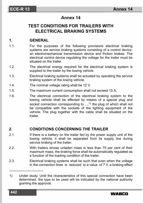
�����442
Annex 14
TEST CONDITIONS FOR TRAILERS WITH ELECTRICAL BRAKING SYSTEMS
1. GENERAL1.1. For the purposes of the following provisions electrical braking
systems are service braking systems consisting of a control device,an electromechanical transmission device and friction brakes. Theelectrical control device regulating the voltage for the trailer must besituated on the trailer.
1.2. The electrical energy required for the electrical braking system issupplied to the trailer by the towing vehicle.
1.3. Electrical braking systems shall be actuated by operating the servicebraking system of the towing vehicle.
1.4. The nominal voltage rating shall be 12 V.1.5. The maximum current consumption shall not exceed 15 A.1.6. The electrical connection of the electrical braking system to the
towing vehicle shall be effected by means of a special plug andsocket connection corresponding to ...,1) the plug of which shall notbe compatible with the sockets of the lighting equipment of thevehicle. The plug together with the cable shall be situated on thetrailer.
2. CONDITIONS CONCERNING THE TRAILER2.1. If there is a battery on the trailer fed by the power supply unit of the
towing vehicle, it shall be separated from its supply line duringservice braking of the trailer.
2.2. With trailers whose unladen mass is less than 75 per cent of theirmaximum mass, the braking force shall be automatically regulated asa function of the loading condition of the trailer.
2.3. Electrical braking systems shall be such that even when the voltagein the connection lines is reduced to a value of 7 V, a braking effect
Annex 14ECE-R 13
1) Under study. Until the characteristics of this special connection have beendetermined, the type to be used will be indicated by the national authoritygranting the approval.

����� 443
of 20 per cent of the (sum of the) maximum stationary axle load(s) ismaintained.
2.4. Control devices for regulating the braking force, which react to theinclination in the direction of travel (pendulum, spring-mass-system,liquid-inertia-switch) shall, if the trailer has more than one axle and avertically adjustable towing device, be attached to the chassis. In thecase of single-axle trailers and trailers with close-coupled axleswhere the axle spread is less than 1 metre, these control devicesshall be equipped with a mechanism indicating its horizontal position(e.g. spirit level) and shall be manually adjustable to allow themechanism to be set in the horizontal plane in line with the directionof travel of the vehicle.
2.5. The relay for actuating the braking current in accordance withparagraph 5.2.1.19.2. of this Regulation, which is connected to theactuating line, shall be situated on the trailer.
2.6. A dummy socket shall be provided for the plug.2.7. A tell-tale shall be provided at the control device, lighting up at any
brake application and indicating the proper functioning of the trailerelectrical braking system.
3. PERFORMANCE3.1. Electrical braking systems shall respond at a deceleration of the
tractor/trailer combination of not more than 0.4 m/s2.3.2. The braking effect may commence with an initial braking force, which
shall not be higher than 10 per cent of the (sum of the) maximumstationary axle load(s) nor higher than 13 per cent of the (sum of the)stationary axle load(s) of the unladen trailer.
3.3. The braking forces may also be increased in steps. At higher levels ofthe braking forces than those referred to in paragraph 3.2. of thisannex these steps shall not be higher than 6 per cent of the (sum ofthe) maximum stationary axle load(s) nor higher than 8 per cent ofthe (sum of the) stationary axle load(s) of the unladen trailer.However, in the case of single-axle trailers having a maximum massnot exceeding 1.5 tonnes, the first step must not exceed 7 per cent ofthe (sum of the) maximun stationary axle load(s) of the trailer. Anincrease of 1 per cent of this value is permitted for the subsequentsteps (example: first step 7 per cent, second step 8 per cent, third
Annex 14 ECE-R 13

�����444
step 9 per cent, etc; any further step should not exceed 10 per cent).For the purpose of these provisions a two-axle trailer having awheelbase shorter than 1m will be considered as a single-axle trailer.
3.4. The prescribed braking force of the trailer of at least 50 per cent ofthe maximum total axle load shall be attained - with maximum mass -in the case of a mean fully developed deceleration of the tractor/trailer combination of not more than 5.9 m/s2 with single-axle trailersand of not more than 5.6 m/s2 with multi-axle trailers. Trailers withclose-coupled axles where the axle spread is less than 1 m are alsoconsidered as single-axle trailers within the meaning of thisprovision. Moreover, the limits as defined in the appendix to thisannex must be observed. If the braking force is regulated in steps,they shall lie within the range shown in the appendix to this annex.
3.5. The test shall be carried out with an initial speed of 60 km/h.3.6. Automatic braking of the trailer shall be provided in accordance with
the conditions of paragraph 5.2.2.9 of this Regulation. If thisautomatic braking action requires electrical energy, a trailer brakingforce of at least 25 per cent of the maximum total axle load shall beachieved for at least 15 minutes to satisfy the above-mentionedconditions.
Annex 14ECE-R 13

����� 445
Annex 14 - Appendix
Compatibility of the braking rate of the trailer and the mean fully developed deceler-ation of the tractor/trailer combination (trailer laden and unladen).
a = single-axle andmulti-axle trailers
b = multi-axle trailers
c = single-axle trailers
Notes:1. Limits indicated in the diagram refer to laden and unladen trailers.
When the trailer unladen mass exceeds 75 per cent of its maximummass, limits shall be applied only to ”laden“ conditions.
2. Limits indicated in the diagram do not affect the provisions of thisannex regarding the minimum braking performances required.However, if braking performances obtained during test - inaccordance with provisions indicated in paragraph 3.4. of this annex -are greater than those required, said performances shall not exceedthe limits indicated in the above diagram.TR = sum of braking forces at periphery of all wheels of trailer.
PR = total normal static reaction of road surface on wheels of trailer.
J = mean fully-developed deceleration of tractor/trailer combination.
TRPR-------
Annex 14 - Appendix ECE-R 13
J m/s2

�����446
Annex 15
INERTIA DYNAMOMETER TEST METHOD FOR BRAKE LININGS
1. GENERAL1.1. The procedure described in this annex may be applied in the event of
a modification of vehicle type resulting from the fitting of brake liningsof another type to vehicles which have been approved in accordancewith this Regulation.
1.2. The alternative types of brake linings shall be checked by comparingtheir performance with that obtained from the brake linings with whichthe vehicle was equipped at the time of approval and conforming tothe components identified in the relevant information document, amodel of which is given in annex 2 to this Regulation.
1.3. The Technical Service responsible for conducting approval tests mayat its discretion require comparison of the performance of the brakelinings to be carried out in accordance with the relevant provisionscontained in annex 4 to this Regulation.
1.4. Application for approval by comparison shall be made by the vehiclemanufacturer or by his duly accredited representative.
1.5. In the context of this annex ”vehicle“ shall mean the vehicle-typeapproved according to this Regulation and for which it is requestedthat the comparison shall be considered satisfactory.
2. TEST EQUIPMENT2.1. A dynamometer having the following characteristics shall be used for
the tests:2.1.1. It shall be capable of generating the inertia required by paragraph
3.1. of this annex, and have the capacity to meet the requirementsprescribed by paragraphs 1.5., 1.6. and 1.7. of annex 4 to thisRegulation with respect to Type-I, Type-II and Type-III tests.
2.1.2. The brakes fitted shall be identical with those of the original vehicletype concerned.
2.1.3. Air cooling, if provided, shall be in accordance with paragraph 3.4. ofthis annex.
2.1.4. The instrumentation for the test shall be capable of providing at leastthe following data:
Annex 15ECE-R 13
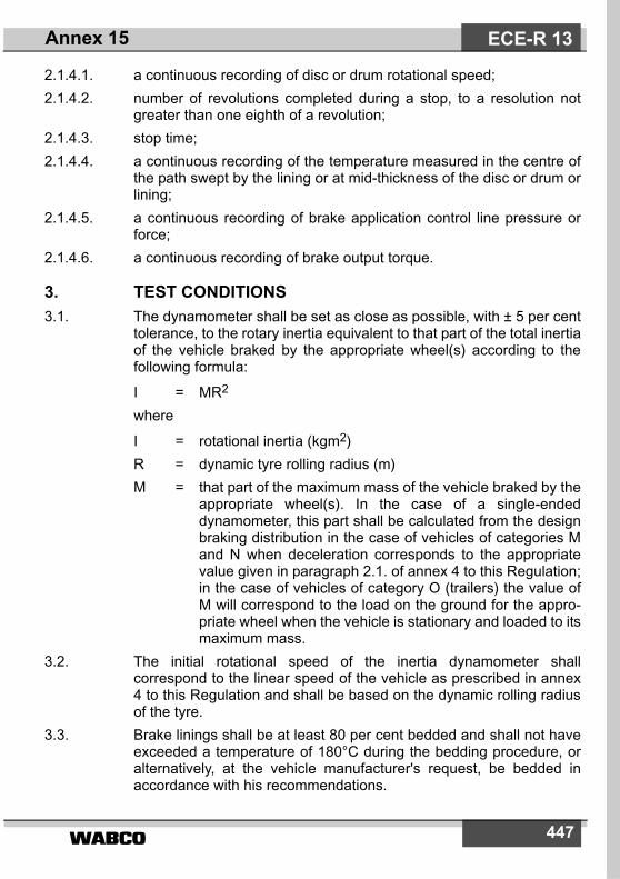
����� 447
2.1.4.1. a continuous recording of disc or drum rotational speed;2.1.4.2. number of revolutions completed during a stop, to a resolution not
greater than one eighth of a revolution;2.1.4.3. stop time;2.1.4.4. a continuous recording of the temperature measured in the centre of
the path swept by the lining or at mid-thickness of the disc or drum orlining;
2.1.4.5. a continuous recording of brake application control line pressure orforce;
2.1.4.6. a continuous recording of brake output torque.
3. TEST CONDITIONS3.1. The dynamometer shall be set as close as possible, with ± 5 per cent
tolerance, to the rotary inertia equivalent to that part of the total inertiaof the vehicle braked by the appropriate wheel(s) according to thefollowing formula:
I = MR2
where
I = rotational inertia (kgm2)R = dynamic tyre rolling radius (m)M = that part of the maximum mass of the vehicle braked by the
appropriate wheel(s). In the case of a single-endeddynamometer, this part shall be calculated from the designbraking distribution in the case of vehicles of categories Mand N when deceleration corresponds to the appropriatevalue given in paragraph 2.1. of annex 4 to this Regulation;in the case of vehicles of category O (trailers) the value ofM will correspond to the load on the ground for the appro-priate wheel when the vehicle is stationary and loaded to itsmaximum mass.
3.2. The initial rotational speed of the inertia dynamometer shallcorrespond to the linear speed of the vehicle as prescribed in annex4 to this Regulation and shall be based on the dynamic rolling radiusof the tyre.
3.3. Brake linings shall be at least 80 per cent bedded and shall not haveexceeded a temperature of 180°C during the bedding procedure, oralternatively, at the vehicle manufacturer's request, be bedded inaccordance with his recommendations.
Annex 15 ECE-R 13
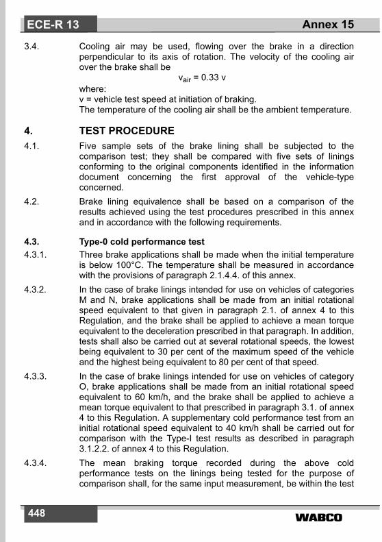
�����448
3.4. Cooling air may be used, flowing over the brake in a directionperpendicular to its axis of rotation. The velocity of the cooling airover the brake shall be
vair = 0.33 vwhere:v = vehicle test speed at initiation of braking.The temperature of the cooling air shall be the ambient temperature.
4. TEST PROCEDURE4.1. Five sample sets of the brake lining shall be subjected to the
comparison test; they shall be compared with five sets of liningsconforming to the original components identified in the informationdocument concerning the first approval of the vehicle-typeconcerned.
4.2. Brake lining equivalence shall be based on a comparison of theresults achieved using the test procedures prescribed in this annexand in accordance with the following requirements.
4.3. Type-0 cold performance test4.3.1. Three brake applications shall be made when the initial temperature
is below 100°C. The temperature shall be measured in accordancewith the provisions of paragraph 2.1.4.4. of this annex.
4.3.2. In the case of brake linings intended for use on vehicles of categoriesM and N, brake applications shall be made from an initial rotationalspeed equivalent to that given in paragraph 2.1. of annex 4 to thisRegulation, and the brake shall be applied to achieve a mean torqueequivalent to the deceleration prescribed in that paragraph. In addition,tests shall also be carried out at several rotational speeds, the lowestbeing equivalent to 30 per cent of the maximum speed of the vehicleand the highest being equivalent to 80 per cent of that speed.
4.3.3. In the case of brake linings intended for use on vehicles of categoryO, brake applications shall be made from an initial rotational speedequivalent to 60 km/h, and the brake shall be applied to achieve amean torque equivalent to that prescribed in paragraph 3.1. of annex4 to this Regulation. A supplementary cold performance test from aninitial rotational speed equivalent to 40 km/h shall be carried out forcomparison with the Type-I test results as described in paragraph3.1.2.2. of annex 4 to this Regulation.
4.3.4. The mean braking torque recorded during the above coldperformance tests on the linings being tested for the purpose ofcomparison shall, for the same input measurement, be within the test
Annex 15ECE-R 13

����� 449
limits ± 15 per cent of the mean braking torque recorded with thebrake linings conforming to the component identified in the relevantapplication for vehicle type approval.
4.4. Type-I test (fade test)4.4.1. With repeated braking4.4.1.1. Brake linings for vehicles of categories M and N shall be tested
according to the procedure given in paragraph 1.5.1. of annex 4 tothis Regulation.
4.4.2. With continuous braking4.4.2.1. Brake linings for trailers (category O) shall be tested in accordance
with paragraph 1.5.2. of annex 4 to this Regulation.4.4.3. Hot performance4.4.3.1. On completion of the tests required under paragraphs 4.4.1 and
4.4.2. of this annex, the hot braking performance test specified inparagraph 1.5.3. of annex 4 to this Regulation shall be carried out.
4.4.3.2. The mean braking torque recorded during the above hot performancetests on the linings being tested for the purpose of comparison shall,for the same input measurement, be within the test limits ± 15 percent of the mean braking torque recorded with the brake liningsconforming to the component identified in the relevant application forvehicle type approval.
4.5. Type-II test (downhill behaviour test):4.5.1. This test is required only if, on the vehicle-type in question, the
friction brakes are used for the Type-II test.4.5.2. Brake linings for power-driven vehicles of category M3 (except for
those vehicles required to undergo a Type-IIA test according toparagraph 1.6.4. of annex 4 to this Regulation) and category N3,shall be tested according to the procedure set out in paragraph 1.6.1.of annex 4 to this Regulation.
4.5.3. Hot performance4.5.3.1. On completion of the test required under paragraph 4.5.1. of this
annex, the hot performance test specified in paragraph 1.6.3. ofannex 4 to this Regulation shall be carried out.
4.5.3.2. The mean braking torque recorded during the above hot performancetests on the linings being tested for the purpose of comparison shall,for the same input measurement, be within the test limits ± 15 per
Annex 15 ECE-R 13

�����450
cent of the mean braking torque recorded with the brake liningsconforming to the component identified in the relevant application forvehicle type approval.
4.6. FADE TEST (TYPE-III TEST)4.6.1. Test with repeated braking4.6.1.1. Brake linings for trailers of category O4, shall be tested according to
the procedure given in paragraphs 1.7.1. and 1.7.2. of annex 4 to thisRegulation.
4.6.2. Hot performance4.6.2.1. On completion of the tests required under paragraph 4.6.1., the hot
braking performance test specified in paragraph 1.7.2. of annex 4 tothis Regulation shall be carried out.
4.6.2.2. The mean braking torque during the above hot performance tests onthe linings being tested for the purpose of comparison shall, for thesame input measurement, be within the test limits ± 15 per cent of themean braking torque recorded with the brake linings conforming tothe component identified in the relevant application for vehicle typeapproval.
5. INSPECTION OF BRAKE LININGS5.1. Brake linings shall be visually inspected on completion of the above
tests to check that they are in satisfactory condition for continued usein normal service.
Annex 15ECE-R 13

����� 451
Annex 16
(Reserved)
Annex 16 ECE-R 13

�����452
Annex 17
TEST PROCEDURE TO ASSESS THE FUNCTIONAL COMPATIBILITY OF VEHICLES EQUIPPED
WITH ELECTRIC CONTROL LINES
1. GENERAL
1.1. This annex defines a procedure that may be used to check towingand towed vehicles equipped with an electric control line against thefunctional and performance requirements referred to in paragraph5.1.3.6.1. of this Regulation. Alternative procedures may be used atthe discretion of the Technical Service if an equivalent level ofchecking integrity can be established.
1.2. The references to ISO 7638 within this annex apply to ISO 7638-1:1997 for 24V applications and ISO 7638-2:1997 for 12V applica-tions.
2. INFORMATION DOCUMENT2.1. The vehicle manufacturer/system supplier shall supply to the
Technical Service an Information Document that contains at least thefollowing:
2.1.1. a schematic of the vehicle braking system;2.1.2. evidence that the interface, including the physical layer, data link
layer and the application layer and the respective position ofsupported messages and parameters, complies with ISO 11992;
2.1.3. a list of supported messages and parameters; and2.1.4. the specification of the motor vehicle with respect to the number of
control circuits that signal the pneumatic and/or electric control lines.
3. TOWING VEHICLES
3.1. ISO 11992 Trailer simulatorThe simulator shall:
3.1.1. have a connector meeting ISO 7638:1997 (7 pin) to connect to thevehicle under test. Pins 6 and 7 of the connector shall be used totransmit and receive messages complying with ISO 11992;
Annex 17ECE-R 13

����� 453
3.1.2. be capable of receiving all of the messages transmitted by the motorvehicle to be type approved and be capable of transmitting all trailermessages defined within ISO 11992-2:2003;
3.1.3. provide a direct or indirect readout of messages, with the parametersin the data field shown in the correct order relative to time; and
3.1.4. include a facility to measure coupling head response time inaccordance with paragraph 2.6. of annex 6 to this Regulation.
3.2. Checking procedure3.2.1. Confirm that the manufacturer's/supplier's information document
demonstrates compliance with the provisions of ISO 11992 withrespect to the physical layer, data link layer and application layer.
3.2.2. Check the following, with the simulator connected to the motorvehicle via the ISO 7638: 1997 interface and whilst all trailermessages relevant to the interface are being transmitted:
3.2.2.1. Control line signalling:3.2.2.1.1. The parameters defined in EBS 12 byte 3 of ISO 11992-2:2003 shall
be checked against the specification of the vehicle as follows:
3.2.2.2. Service/Secondary brake demand:
Control Line Signalling EBS 12 Byte 3
Bits 1 - 2 Bits 5 - 6
Service braking demand generatedfrom one electrical circuit
00b
Service braking demand generatedfrom two electrical circuits
01b
Vehicle is not equipped with a pneu-matic control line 1)
00b
Vehicle is equipped with a pneumatic control line
01b
Annex 17 ECE-R 13
1) This specification of vehicle is prohibited by footnote 1) to paragraph5.1.3.1.3. of this Regulation.

�����454
3.2.2.2.1 The parameters defined in EBS 11 of ISO 11992-2:2003 shall bechecked as follows:
3.2.2.3. Failure warning:3.2.2.3.1. Simulate a permanent failure in the communication line to pin 6 of the
ISO 7638:1997 connector and check that the yellow warning signalspecified in paragraph 5.2.1.29.1.2. of this Regulation is displayed.
3.2.2.3.2. Simulate a permanent failure in the communication line to pin 7 of theISO 7638:1997 connector and check that the yellow warning signalspecified in paragraph 5.2.1.29.1.2. of this Regulation is displayed.
3.2.2.3.3. Simulate message EBS 22, byte 2 with bits 3 - 4 set to 01b and checkthat the red warning signal specified in paragraph 5.2.1.29.1.1. of thisRegulation is displayed.
3.2.2.4. Supply line braking request:For power-driven vehicles which can be operated with trailersconnected via an electric control line only:Only the electric control line shall be connected.Simulate message EBS 22, byte 4 with bits 3 - 4 set to 01b and checkthat when the service brake, secondary brake or parking brake is fullyactuated the pressure in the supply line falls to 1.5 bar within thefollowing two seconds.
Test condition Byte Reference
ElectricalControl LineSignal Value
Service brake pedal and secondary brake control released
3 - 4 0
Service brake pedal fully applied
3 - 4 33280d to 43520d (6.5 to 8.5bar)
Secondary brake fully applied 2) 3 - 4 33280d to 43520d (6.5 to 8.5bar)
Annex 17ECE-R 13
2) Optional on towing vehicles with electric and pneumatic control lines whenthe pneumatic control line fulfils the relevant requirements for secondarybraking

����� 455
Simulate a continuous absence of data communication and checkthat when the service brake, secondary brake or parking brake is fullyactuated the pressure in the supply line falls to 1.5 bar within thefollowing two seconds.
3.2.2.5. Response time:3.2.2.5.1. Check that, with no faults present, the control line response
requirements defined in item 2.6. of annex 6 to this Regulation aremet.
3.2.3. Additional checks3.2.3.1. At the discretion of the Technical Service the checking procedures
defined above may be repeated with the non-braking functionsrelevant to the interface in different states or switched off.
4. TRAILERS
4.1. ISO 11992 Towing vehicle simulatorThe simulator shall:
4.1.1. have a connector meeting ISO 7638:1997 (7 pin) to connect to thevehicle under test. Pins 6 and 7 of the connector shall be used totransmit and receive messages complying with ISO 11992: 2003;
4.1.2. have a failure warning display and an electrical power supply for thetrailer;
4.1.3. shall be capable of receiving all of the messages transmitted by thetrailer to be type approved and be capable of transmitting all motorvehicle messages defined within ISO 11992-2:2003.
4.1.4. provide a direct or indirect readout of messages with the parametersin the data field shown in the correct order relative to time; and
4.1.5. include a facility to measure brake system response time inaccordance with paragraph 3.5.2. of annex 6 to this Regulation.
4.2. Checking procedure4.2.1. Confirm that the manufacturer's/supplier's Information Document
demonstrates compliance with the provisions of ISO 11992: 2003with respect to the physical layer, data link layer and application layer.
4.2.2. Check the following, with the simulator connected to the trailer via theISO 7638:1997 interface and whilst all towing vehicle messagesrelevant to the interface are being transmitted:
4.2.2.1. Service brake system function:
Annex 17 ECE-R 13

�����456
4.2.2.1.1. The trailer response to the parameters defined in EBS 11 of ISO11992-2:2003 shall be checked as follows:The pressure in the supply line at the start of each test shall be�� 7bar and the vehicle shall be laden (the loading condition may besimulated for the purpose of this check).
4.2.2.1.1.1. For trailers equipped with pneumatic and electric control lines:both control lines shall be connectedboth control lines shall be signalled simultaneouslythe simulator shall transmit message byte 3, bits 5 - 6of EBS 12 set to 01b to indicate to the trailer that a pneumatic controlline should be connectedParameters to be checked:
4.2.2.1.1.2. Trailers equipped with pneumatic and electric control lines or anelectric control line only:Only the electric control line shall be connected.The simulator shall transmit the following messages:Byte 3, bits 5 - 6 of EBS 12 set to 00b to indicate to the trailer that apneumatic control line is not available, and byte 3, bits 1 - 2 of EBS12 set to 01b to indicate to the trailer that the electric control linesignal is generated from two electric circuits.
Message Transmitted by theSimulator
Pressure at the Brake Chambers
Byte Reference
Digital DemandValue
3 - 4 0 0 bar
3 - 4 33280d (6.5 bar)
As defined in the vehicle manufacturer's brake calculation
Annex 17ECE-R 13
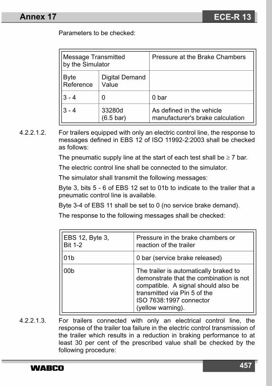
����� 457
Parameters to be checked:
4.2.2.1.2. For trailers equipped with only an electric control line, the response tomessages defined in EBS 12 of ISO 11992-2:2003 shall be checkedas follows:The pneumatic supply line at the start of each test shall be � 7 bar.The electric control line shall be connected to the simulator.The simulator shall transmit the following messages:Byte 3, bits 5 - 6 of EBS 12 set to 01b to indicate to the trailer that apneumatic control line is available.Byte 3-4 of EBS 11 shall be set to 0 (no service brake demand).The response to the following messages shall be checked:
4.2.2.1.3. For trailers connected with only an electrical control line, theresponse of the trailer toa failure in the electric control transmission ofthe trailer which results in a reduction in braking performance to atleast 30 per cent of the prescribed value shall be checked by thefollowing procedure:
Message Transmitted by the Simulator
Pressure at the Brake Chambers
Byte Reference
Digital DemandValue
3 - 4 0 0 bar
3 - 4 33280d (6.5 bar)
As defined in the vehicle manufacturer's brake calculation
EBS 12, Byte 3, Bit 1-2
Pressure in the brake chambers or reaction of the trailer
01b 0 bar (service brake released)
00b The trailer is automatically braked todemonstrate that the combination is notcompatible. A signal should also betransmitted via Pin 5 of the ISO 7638:1997 connector (yellow warning).
Annex 17 ECE-R 13

458
The pneumatic supply line at the start of each test shall be ≥ 7.0 bar.The electric control line shall be connected to the simulator.Byte 3, bits 5 - 6 of EBS 12 set to 00b to indicate to the trailer that apneumatic control line is not available.Byte 3, bits 1 - 2 of EBS 12 set to 01b to indicate to the trailer that theelectric control line signal is generated from two independent circuits.The following shall be checked:
4.2.2.2. Failure warning4.2.2.2.1. Check that the appropriate warning message or signal is transmitted
under the following conditions:4.2.2.2.1.1. Where a permanent failure within the electric control transmission of
the trailer braking system precludes the service braking performancebeing met, simulate such a failure and check that byte 2, bits 3 - 4 ofEBS 22 transmitted by the trailer is set to 01b. A signal should alsobe transmitted via pin 5 of the ISO 7638:1997 connector (yellowwarning).
4.2.2.2.1.2. Reduce the voltage on pins 1 and 2 of the ISO 7638:1997 connectorto below a value nominated by the manufacturer which precludes theservice braking system performance from being fulfilled and checkthat byte 2, bits 3 - 4 of EBS 22 transmitted by the trailer are set to01b. A signal should also be transmitted via pin 5 of the ISO7638:1997 connector (yellow warning).
Test Condition Brake System Responce
With no faults present in the trailer braking system
Check that the braking system is communicating with the simulatorand that Byte 4, bits 3-4 of EBS22 is set to 00b.
Introduce a failure in the electric control transmission of the trailer braking system that prevents at least 30 percent of the prescribed braking performance from being maintained
Check that Byte 4, bits 3-4 of EBS22 is set to 01b
or
The data communications to thesimulator has been terminated
Annex 17ECE-R 13

����� 459
4.2.2.2.1.3. Check compliance with the provisions of paragraph 5.2.2.16. of thisRegulation by isolating the supply line. Reduce the pressure in thetrailer pressure storage system to the value nominated by themanufacturer. Check that byte 2, bits 3 - 4 of EBS 22 transmitted bythe trailer is set to 01b and that byte 1, bits 7 - 8 of EBS 23 is set to00. A signal should also be transmitted via pin 5 of the ISO7638:1997 connector (yellow warning).
4.2.2.2.1.4. When the electrical part of the braking equipment is first energisedcheck that byte 2, bits 3 - 4 of EBS 22 transmitted by the trailer is setto 01b. After the braking system has checked that no defects thatrequire identification by the red warning signal are present the abovemessage should be set to 00b.
4.2.2.3. Response time checking4.2.2.3.1. Check that, with no faults present, the braking system response time
requirements defined in paragraph 3.5.2. of annex 6 to thisRegulation are met.
4.2.3. Additional checks4.2.3.1. At the discretion of the Technical Service the checking procedures
defined above may be repeated with the non-braking messagesrelevant to the interface in different states or switched off.Where repeated measurements of the braking system response timeare carried out, variations in the value recorded may occur due to thereaction of the vehicle pneumatics. In all cases the prescribedresponse time requirements shall be met.
Annex 17 ECE-R 13

�����460
Annex 18
SPECIAL REQUIREMENTS TO BE APPLIED TO THE SAFETY ASPECTS OF COMPLEX ELECTRONIC
VEHICLE CONTROL SYSTEMS
1. GENERALThis annex defines the special requirements for documentation, faultstrategy and verification with respect to the safety aspects ofcomplex electronic vehicle control systems (paragraph 2.3. below) asfar as this Regulation is concerned.This annex may also be called, by special paragraphs in thisRegulation, for safety related functions which are controlled byelectronic system(s).This annex does not specify the performance criteria for ”TheSystem“ but covers the methodology applied to the design processand the information which must be disclosed to the technical service,for type approval purposes.This information shall show that ”The System“ respects, undernormal and fault conditions, all the appropriate performancerequirements specified elsewhere in this Regulation.
2. DEFINITIONSFor the purposes of this annex,
2.1. ”Safety concept“ is a description of the measures designed into thesystem, for example within the electronic units, so as to addresssystem integrity and thereby ensure safe operation even in the eventof an electrical failure.The possibility of a fall-back to partial operation or even to a back-upsystem for vital vehicle functions may be a part of the safety concept.
2.2. ”Electronic control system“ means a combination of units, designedto cooperate in the production of the stated vehicle control functionby electronic data processing.Such systems, often controlled by software, are built from discretefunctional components such as sensors, electronic control units andactuators and connected by transmission links. They may includemechanical, electro-pneumatic or electro-hydraulic elements.
Annex 18ECE-R 13
����� 461
”The System“, referred to herein, is the one for which type approval isbeing sought.
2.3. ”Complex electronic vehicle control systems“ are those electroniccontrol systems which are subject to a hierarchy of control in which acontrolled function may be over-ridden by a higher level electroniccontrol system/function.A function which is over-ridden becomes part of the complex system.
2.4. ”Higher-level control“ systems/functions are those which employadditional processing and/or sensing provisions to modify vehiclebehaviour by commanding variations in the normal function(s) of thevehicle control system.This allows complex systems to automatically change their objectiveswith a priority which depends on the sensed circumstances.
2.5. ”Units“ are the smallest divisions of system components which will beconsidered in this annex, since these combinations of componentswill be treated as single entities for purposes of identification,analysis or replacement.
2.6. ”Transmission links“ are the means used for inter-connectingdistributed units for the purpose of conveying signals, operating dataor an energy supply.This equipment is generally electrical but may, in some part, bemechanical, pneumatic, hydraulic or optical, etc. *)
2.7. ”Range of control“ refers to an output variable and defines the rangeover which the system is likely to exercise control.
2.8. ”Boundary of functional operation“ defines the boundaries of theexternal physical limits within which the system is able to maintaincontrol.
3. DOCUMENTATION
3.1. RequirementsThe manufacturer shall provide a documentation package whichgives access to the basic design of ”The System“ and the means bywhich it is linked to other vehicle systems or by which it directlycontrols output variables.The function(s) of ”The System“ and the safety concept, as laid downby the manufacturer, shall be explained.
Annex 18 ECE-R 13
*) adapted by GRRF/54

�����462
Documentation shall be brief, yet provide evidence that the designand development has had the benefit of expertise from all the systemfields which are involved.For periodic technical inspections, the documentation shall describehow the current operational status of ”The System“ can be checked.
3.1.1. Documentation shall be made available in two parts:(a) The formal documentation package for the approval, containing
the material listed in paragraph 3 (with the exception of that ofparagraph 3.4.4.) which shall be supplied to the technical serv-ice at the time of submission of the type approval application.This will be taken as the basic reference for the verificationprocess set out in paragraph 4. of this annex.
(b) Additional material and analysis data of paragraph 3.4.4., whichshall be retained by the manufacturer, but made open forinspection at the time of type approval.
3.2. Description of the functions of ”The System“A description shall be provided which gives a simple explanation ofall the control functions of ”The System“ and the methods employedto achieve the objectives, including a statement of the mechanism(s)by which control is exercised.
3.2.1. A list of all input and sensed variables shall be provided and theworking range of these defined.
3.2.2. A list of all output variables which are controlled by ”The System“shall be provided and an indication given, in each case, of whetherthe control is direct or via another vehicle system. The range ofcontrol (paragraph 2.7.) exercised on each such variable shall bedefined.
3.2.3. Limits defining the boundaries of functional operation (paragraph2.8.) shall be stated where appropriate to system performance.
3.3. System layout and schematics3.3.1. Inventory of components
A list shall be provided, collating all the units of ”The System“ andmentioning the other vehicle systems which are needed to achievethe control function in question.An outline schematic showing these units in combination, shall beprovided with both the equipment distribution and theinterconnections made clear.
3.3.2. Functions of the ”Units“
Annex 18ECE-R 13

����� 463
The function of each unit of ”The System“ shall be outlined and thesignals linking it with other units or with other vehicle systems shall beshown. This may be provided by a labelled block diagram or otherschematic, or by a description aided by such a diagram.
3.3.3. InterconnectionsInterconnections within ”The System“ shall be shown by a circuitdiagram for the electric transmission links, by an optical-fibre diagramfor optical links, by a piping diagram for pneumatic or hydraulictransmission equipment and by a simplified diagrammatic layout formechanical linkages.
3.3.4. Signal flow and prioritiesThere shall be a clear correspondence between these transmissionlinks and the signals carried between ”Units“.Priorities of signals on multiplexed data paths shall be stated,wherever priority may be an issue affecting performance or safety asfar as this Regulation is concerned.
3.3.5. Identification of ”Units“Each ”Unit“ shall be clearly and unambigously identifiable (e.g. bymarking for hardware and marking or software output for softwarecontent) to provide corresponding hardware and documentationassociation.Where functions are combined within a single ”Unit“ or indeed withina single computer, but shown in multiple blocks in the block diagramfor clarity and ease of explanation, only a single hardwareidentification marking shall be used.The manufacturer shall, by the use of this identification, affirm thatthe equipment supplied conforms to the corresponding document.
3.3.5.1. The identification defines the hardware and software version and,where the latter changes such as to alter the function of the ”Unit“ asfar as this Regulation is concerned, this identification shall also bechanged.
3.4. ”Safety concept“ of the manufacturer3.4.1. The manufacturer shall provide a statement which affirms that the
strategy chosen to achieve ”The System“ objectives will not, undernonfault conditions, prejudice the safe operation of systems whichare subject to the prescriptions of this Regulation.
3.4.2. In respect of software employed in ”The System“, the outlinearchitecture shall be explained and the design methods and tools
Annex 18 ECE-R 13
�����464
used shall be identified. The manufacturer shall be prepared, ifrequired, to show some evidence of the means by which theydetermined the realisation of the system logic, during the design anddevelopment process.
3.4.3. The Manufacturer shall provide the technical authorities with anexplanation of the design provisions built into ”The System“ so as togenerate safe operation under fault conditions. Possible designprovisions for failure in ”The System“ are for example:
(a) Fall-back to operation using a partial system.(b) Change-over to a separate back-up system.(c) Removal of the high level function.
In case of a failure, the driver shall be warned for example bywarning signal or message display. When the system is notdeactivated by the driver, eg. by turning the ignition (run) switch to”off”, or by switching off that particular function if a special switch isprovided for that purpose, the warning shall be present as long as thefault condition persists.
3.4.3.1. If the chosen provision selects a partial performance mode ofoperation under certain fault conditions, then these conditions shallbe stated and the resulting limits of effectiveness defined.
3.4.3.2. If the chosen provision selects a second (back-up) means to realisethe vehicle control system objective, the principles of the change-over mechanism, the logic and level of redundancy and any built inback-up checking features shall be explained and the resulting limitsof back-up effectiveness defined.
3.4.3.3. If the chosen provision selects the removal of the ”Higher LevelFunction“, all the corresponding output control signals associatedwith this function shall be inhibited, and in such a manner as to limitthe transition disturbance.
3.4.4. The documentation shall be supported, by an analysis which shows,in overall terms, how the system will behave on the occurrence ofany one of those specified faults which will have a bearing on vehiclecontrol performance or safety.This may be based on a Failure Mode and Effect Analysis (FMEA), aFault Tree Analysis (FTA) or any similar process appropriate tosystem safety considerations.
Annex 18ECE-R 13

����� 465
The chosen analytical approach(es) shall be established andmaintained by the Manufacturer and shall be made open forinspection by the technical service at the time of the type approval.
3.4.4.1. This documentation shall itemise the parameters being monitoredand shall set out, for each fault condition of the type defined inparagraph 3.4.4. above, the warning signal to be given to the driverand/or to service/technical inspection personnel.
4. VERIFICATION AND TEST4.1. The functional operation of ”The System“, as laid out in the
documents required in paragraph 3., shall be tested as follows:4.1.1. Verification of the function of ”The System“
As the means of establishing the normal operational levels,verification of the performance of the vehicle system under non-faultconditions shall be conducted against the manufacturer's basicbenchmark specification unless this is subject to a specifiedperformance test as part of the approval procedure of this or anotherRegulation.
4.1.2. Verification of the ”Safety concept“ of paragraph 3.4.The reaction of ”The System“ shall, at the discretion of the typeapproval authority, be checked under the influence of a failure in anyindividual unit by applying corresponding output signals to electricalunits or mechanical elements in order to simulate the effects ofinternal faults within the unit.
4.1.2.1. The verification results shall correspond with the documentedsummary of the failure analysis, to a level of overall effect such thatthe safety concept and execution are confirmed as being adequate.
Annex 18 ECE-R 13

�����466
Annex 19
PERFORMANCE TESTING OF BRAKING COMPONENTS
1 . GeneralThis annex defines the test procedures applicable in defining theperformance of the following:
1.1.1. Diaphragm brakes chambers (refer to paragraph 2).1.1.2. Spring brakes (refer to item 3).1.1.3. Trailer brakes - cold performance characteristics
(refer to paragraph 4.).1.1.4. Anti-lock braking systems (refer to paragraph 5.)
(NOTE: Procedures for determining the fade test performance fortrailer brakes and automatic brake wear adjustment devices aredefined in annex 11 of this Regulation).
1.2. The above test reports may be used in conjunction with theprocedures defined in annex 20 to this Regulation or at the time ofevaluating a trailer which is being subject to actual performancerequirements defined for the respective trailer.
2. Performance characteristics for diaphragm brake chambers
2.1. General2.1.1. This section defines the procedure by which the thrust/stroke/
pressure characteristics are determined for diaphragm brakechambers which are used in compressed air braking systems 1) togenerate forces required in brakes with mechanical actuation.
2.1.2. The verified performance characteristics declared by themanufacturer shall be used in all calculations relating to the brakecompatibility requirements of annex 10, the Type-0 cold servicebraking performance requirements of annex 20 and thedetermination of the available actuator stroke with respect to theverification of the hot performance of annex 11.
Annex 19ECE-R 13
1) Other brake chamber designs may be approved upon presentation of equiv-alent information.
����� 467
2.2. Test procedure:2.2.1. Zero datum position of the brake chamber is to be taken as the non-
pressurised position.2.2.2. In nominal pressure increments of � 1 bar, through a pressure range
of 1 to � 8 bar, the corresponding thrust generated is to be monitoredover the full stroke range available for a stroke displacement of � 10mm/s or a stroke increment of � 10 mm and whilst not permitting theapplied pressure to deviate ± 0.05 bar.
2.2.3. For each pressure increment the corresponding average thrust (ThA)and the effective stroke (sp) will be determined as per appendix 7 ofthis annex.
2.3. Verification2.3.1. With reference to appendix 1 of this annex, paragraphs 3.1., 3.2. and
3.3., a minimum of 6 samples are to be tested, with a verificationreport being issued, providing no one result deviates by more than 4per cent of the declared characteristics. However, with respect to theverification of the sp characteristics the pressure range over whichthe 4 per cent tolerance is fulfilled shall be recorded and specified inparagraph 3.3.1. of appendix 1 of this annex. Outside of this pressurerange the tolerance may exceed 4 per cent.
2.3.2. The test results recorded shall be reported on a form, a model ofwhich is shown in appendix 2 to this annex and shall be included withthe verification report detailed within paragraph 2.4.
2.4. Verification report:2.4.1. The manufacturer's declared performance characteristics, verified by
the test results recorded in accordance with paragraph 2.3.2., shallbe reported on a form, a model of which is shown in appendix 1 tothis annex.
3. Performance characteristics for spring brakes
3.1. General:3.1.1. This section defines the procedure by which the thrust/stroke/
pressure characteristics are determined for spring brakes 2) that areused in compressed air braking systems to generate forces requiredin brakes with mechanical actuation.
Annex 19 ECE-R 13
2) Other spring brake designs may be approved upon presentation of equiva-lent information.
�����468
3.1.2. The performance characteristics declared by the manufacturer shallbe used in all calculations relating to the parking brakingperformance requirements of annex 20.
3.2. Test procedure:3.2.1. Zero datum position of the spring brake chamber is to be taken as the
fully pressurised position.3.2.2. In nominal stroke increments of � 10 mm, the corresponding thrust
generated is to be monitored over the full stroke range available atzero pressure.
3.2.3. The pressure shall then be gradually increased until the stroke is 10mm from the zero datum position, and this pressure, defined as therelease pressure, shall be recorded.
3.2.4. The pressure shall then be increased to 8.5 bar, or the maximumworking pressure declared by the manufacturer, whichever is lower.
3.3. Verification:3.3.1. With reference to appendix 3, items 2.1., 3.1., 3.2. and 3.3., a
minimum of 6 samples shall be tested, with a verification report beingissued providing the following conditions are met:
3.3.1.1. Over a range of stroke from 10 mm to 2/3 of the maximum stroke, noone result, measured in accordance with item 3.2.2., deviates bymore than 6 per cent from the declared characteristics.
3.3.1.2. No one result, measured in accordance with paragraph 3.2.3.,exceeds the declared value.
3.3.1.3. Each spring brake continues to function correctly after completion ofthe test in accordance with paragraph 3.2.4.
3.3.2. The test results recorded shall be reported on a form, a model ofwhich is shown in appendix 4 to this annex, and shall be includedwith the verification report detailed within paragraph 3.4.
3.4. Verification report:3.4.1. The manufacturer's declared performance characteristics, verified by
the test results recorded in accordance with paragraph 3.3.2., shallbe reported on a form, a model of which is shown in appendix 3 tothis annex.
4. Cold performance characteristics for trailer brakes4.1. General:
Annex 19ECE-R 13
����� 469
4.1.1. This procedure covers the testing of the ”cold” performancecharacteristics of air operated S-cam and disc-brakes 3) fitted totrailers.
4.1.2. The performance characteristics declared by the manufacturer shallbe used for all calculations relating to the braking compatibilityrequirements of annex 10 and to the Type-0 cold service braking andparking braking performance requirements of annex 20.
4.2. Brake factor and brake threshold torque4.2.1. The preparation of the brake shall be in accordance with paragraph
4.4.2. of this annex.4.2.2. The brake factor is the resultant amplification factor achieved through
the friction forces generated by the individual components comprisingthe brake assembly, and is expressed as a ratio between the inputtorque and the output torque. This brake factor is denoted by thesymbol BF and shall be verified for each of the lining or pad materialsspecified in paragraph 4.3.1.3.
4.2.3. The brake threshold torque shall be expressed in a manner thatremains valid for variations of brake actuation and is denoted by thesymbol Co.
4.2.4. The values of BF shall remain valid for variations of the followingparameters:
4.2.4.1. Mass per brake up to that defined in paragraph 4.3.1.5.4.2.4.2. Dimensions and characteristics of external components used to
actuate the brake.4.2.4.3. Wheel size/tyre dimensions.
4.3. Information document4.3.1. The brake manufacturer shall provide the Technical Service with at
least the following information:4.3.1.1. A description of the brake type, model, size etc.4.3.1.2. Details of the brake geometry4.3.1.3. The make and type of brake lining(s) or brake pad(s)4.3.1.4. The brake drum or brake disc material4.3.1.5. The maximum technically permitted mass for the brake
Annex 19 ECE-R 13
3) Other brake designs may be approved upon presentation of equivalent infor-mation.
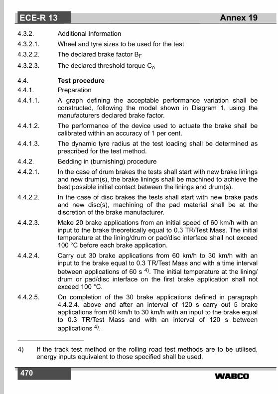
�����470
4.3.2. Additional Information4.3.2.1. Wheel and tyre sizes to be used for the test4.3.2.2. The declared brake factor BF
4.3.2.3. The declared threshold torque Co
4.4. Test procedure4.4.1. Preparation4.4.1.1. A graph defining the acceptable performance variation shall be
constructed, following the model shown in Diagram 1, using themanufacturers declared brake factor.
4.4.1.2. The performance of the device used to actuate the brake shall becalibrated within an accuracy of 1 per cent.
4.4.1.3. The dynamic tyre radius at the test loading shall be determined asprescribed for the test method.
4.4.2. Bedding in (burnishing) procedure4.4.2.1. In the case of drum brakes the tests shall start with new brake linings
and new drum(s), the brake linings shall be machined to achieve thebest possible initial contact between the linings and drum(s).
4.4.2.2. In the case of disc brakes the tests shall start with new brake padsand new disc(s), machining of the pad material shall be at thediscretion of the brake manufacturer.
4.4.2.3. Make 20 brake applications from an initial speed of 60 km/h with aninput to the brake theoretically equal to 0.3 TR/Test Mass. The initialtemperature at the lining/drum or pad/disc interface shall not exceed100 °C before each brake application.
4.4.2.4. Carry out 30 brake applications from 60 km/h to 30 km/h with aninput to the brake equal to 0.3 TR/Test Mass and with a time intervalbetween applications of 60 s 4). The initial temperature at the lining/drum or pad/disc interface on the first brake application shall notexceed 100 °C.
4.4.2.5. On completion of the 30 brake applications defined in paragraph4.4.2.4. above and after an interval of 120 s carry out 5 brakeapplications from 60 km/h to 30 km/h with an input to the brake equalto 0.3 TR/Test Mass and with an interval of 120 s betweenapplications 4).
Annex 19ECE-R 13
4) If the track test method or the rolling road test methods are to be utilised,energy inputs equivalent to those specified shall be used.

����� 471
4.4.2.6. Make 20 brake applications from an initial speed of 60 km/h with aninput to the brake equal to 0.3 TR/Test Mass. The initial temperatureat the lining/drum or pad/disc interface shall not exceed 150° Cbefore each brake application.
4.4.2.7. Carry out a performance check as follows:4.4.2.7.1. Determine the input torque to produce theoretical performance
values equivalent to 0.2, 0.35 and 0.5 ± 0.05 TR/Test Mass.4.4.2.7.2. Once the input torque value has been determined for each braking
rate, this value shall remain constant throughout each andsubsequent brake applications (e.g. constant pressure).
4.4.2.7.3. Make a brake application with each of the input torques determined inparagraph 4.4.2.7.1. from an initial speed of 60 km/h. The initialtemperature at the lining/drum or pad/disc interfaces shall not exceed100 °C before each application.
4.4.2.8. Repeat the procedures defined in paragraphs 4.4.2.6. and 4.4.2.7.3.above until the performance of five consecutive non monotonicmeasurements at each constant input value has stabilised within atolerance of ± 5 per cent.
4.4.2.9. In the case of this procedure being carried out on an inertiadynamometer or rolling road, unlimited use of cooling air is permitted.
4.4.3. Verification test4.4.3.1. The temperature measured at the lining/drum or pad/disc interface
shall not exceed 100 °C, at the start of each brake application.4.4.3.2. The brake threshold torque shall be determined from the measured
value of brake input by reference to a calibrated input device.4.4.3.3. The initial speed for all brake applications is 60 ± 2 km/h.4.4.3.4. A minimum of six consecutive brake applications shall be made from
0.15 to 0.55 TR/Test Mass at ascending increments of applicationpressure, following by six brake applications made with the sameapplication pressures in descending increments.
4.4.3.5. For each of the brake applications in paragraph 4.4.3.4. the brakingrate is calculated, corrected to take account of rolling resistance, andplotted on the graph specified in paragraph 4.4.1.1. of this annex.
4.5. Test methods4.5.1. Track test4.5.1.1. The brake performance test shall be carried out on a single axle only.4.5.1.2. The tests shall be carried out on a straight level track, with a surface
affording good adhesion, and performed when there is no wind liableto affect the results.
Annex 19 ECE-R 13

�����472
4.5.1.3. The trailer shall be loaded (as closely as possible) to the maximumtechnically permitted mass for each brake, however, additional massmay be added if required to ensure that sufficient mass is over theaxle under test to achieve a braking rate of 0.55 TR/(maximumtechnically permitted mass per brake) without wheel lock.
4.5.1.4. The dynamic rolling radius of the tyre may be verified at low speed,< 10 km/h, by measuring the distance travelled as a function wheelrevolutions, the minimum number of revolutions required todetermine the dynamic rolling radius is 10.
4.5.1.5. The rolling resistance of the vehicle combination is to be determinedby measuring the time taken for the vehicle speed to reduce from 55to 45 km/h and the distance covered, when tested in the samedirection in which the verification test will be carried out and with theengine disconnected and any endurance brake system disengaged.
4.5.1.6. Only the brakes of the axle under test shall be actuated and reach aninput pressure at the brake input device of 90 ± 3 per cent (aftermaximum build up time of 0.7 s) of its asymptotic value. The test shallbe carried out with the engine disconnected and any endurancebraking system disengaged.
4.5.1.7. The brakes shall be closely adjusted at the start of the test.4.5.1.8. The brake input for the purpose of calculating the brake threshold
torque shall be determined by lifting the wheel and gradually applyingthe brake whilst the wheel is rotated by hand until resistance isdetected.
4.5.1.9. The final speed v2 shall be determined in accordance with annex 11,appendix 2, paragraph 3.1.5.
4.5.1.10. The braking performance of the axle under test shall be determinedby calculating the deceleration determined from a directmeasurement of velocity and distance between 0.8 v1 and v2, wherev2 shall not be less than 0.1 v1. This shall be deemed to beequivalent to the mean fully developed deceleration (MFDD) asdefined in annex 4 above.
4.5.2. Inertia dynamometer test4.5.2.1. The test shall be carried out on a single brake assembly.4.5.2.2. The test machine shall be capable of generating the inertia required
by paragraph 4.5.2.5. of this annex.4.5.2.3. The test machine shall be calibrated for speed and brake output
torque within an accuracy of 2 per cent.4.5.2.4. The instrumentation for the test shall be capable of providing at least
the following data:
Annex 19ECE-R 13

����� 473
4.5.2.4.1. A continuous recording of brake application pressure or force.4.5.2.4.2. A continuous recording of brake output torque.4.5.2.4.3. A continuous recording of the temperature measured at the lining/
drum or pad/disc interface.4.5.2.4.4. Speed during the test.4.5.2.5. The inertia (IT) of the dynamometer shall be set as close as possible,
with ± 5 per cent tolerance, including the internal friction of thedynamometer, to that part of the linear inertia of the vehicle actingupon one wheel necessary for a performance of 0.55TR/maximumtechnically permitted mass according to the following formula:
IT = Pd • R2
where
IT = actual rotary inertia (kgm2)R = tyre rolling radius defined by the formula 0.485 DD = d + 2H 5)
d = rim diameter conventional number (mm)H = nominal section height (mm) = S1 x 0.01 RaS1 = Section width (mm)Ra = nominal aspect ratioPd = maximum technically permitted mass/brake as defined in
paragraph 4.3.1.5.4.5.2.6. Cooling air at ambient temperature may be used, flowing at a velocity
not exceeding 0.33 v over the brake in a direction perpendicular to itsaxis of rotation. The temperatur of the cooling air shall be the ambienttemperature.
4.5.2.7. The brake shall be closely adjusted at the start of the test.4.5.2.8. The brake input for the purpose of calculating the brake threshold
torque shall be determined by gradually applying the brake until theonset of brake torque generation is observed.
4.5.2.9. The brake performance shall be determined by applying the followingformula to the measured brake output torque
braking rate = Mt R�
Ig---------------
Annex 19 ECE-R 13
5) Outer diameter of tyre, as defined in Regulation No. 54.

�����474
where:Mt = average brake output torque (Nm) - based on distanceg = deceleration due to gravity (m/s2)The average brake output torque (Mt) shall be calculated from thedeceleration determined from a direct measurement of velocity anddistance between 0.8 v1 and 0.1 v1. This shall be deemed to beequivalent to the mean fully developed deceleration (MFDD) asdefined in annex 4 above.
4.5.3. Rolling road test4.5.3.1. The test will be carried out on single axle with one or two brakes.4.5.3.2. The test machine shall have a calibrated means of imposing load to
simulate the required mass for the brake(s) to be tested.4.5.3.3. The test machine shall be calibrated for speed and brake torque
within an accuracy of 2 per cent taking into account the internalfriction characteristics. The dynamic rolling radius of the tyre (R) shallbe determined by measuring the rotational speed of the rolling roadand the unbraked wheels of the axle under test at a speed equivalentto 60 km/h, and calculated by the formula
where:RR = radius of the rolling road
nD = rotational speed of rolling road
nw = rotational speed of the unbraked wheels of the axle
4.5.3.4. Cooling air at ambient temperature may be used, flowing at a velocitynot exceeding 0.33 v over the brake(s). The temperatur of the coolingair shall be the ambient temperature.
4.5.3.5. The brake(s) shall be closely adjusted at the start of the test.4.5.3.6. The brake input for the purpose of calculating the brake threshold
torque shall be determined by gradually applying brake(s) until theonset of brake torque generation is observed.
4.5.3.7. The brake performance shall be determined by measuring the brakeforce at the periphery of the tyre calculated to braking rate, taking intoaccount the rolling resistance. The rolling resistance of the loadedaxle will be determined by measuring the force at the periphery of thetyre at a speed of 60 km/h.
R RRnDnW-------�=
Annex 19ECE-R 13

����� 475
The average brake output torque (Mt) shall be based on themeasured values between the moment the application pressure/forcereaches its asymptotic value from the onset of pressure rise at thebrake input device and when the energy input has reached the valueW60 that is defined in paragraph 4.5.3.8.
4.5.3.8. For determining the braking rate an energy input W60 equivalent tothe kinetic energy of the corresponding mass for the brake under testwhen braked from 60 km/h to standstill, must be taken into account.where:
4.5.3.8.1. If the test speed v cannot be maintained at 60 ± 2 km/h during themeasurement of the braking rate according to paragraph 4.5.3.8., thebraking rate shall be determined from the direct measurement ofbrake force FB and/or brake output torque Mt, so that themeasurement of this/these parameter(s) are not affected by thedynamic forces of the inertia mass of the rolling road test machine.
4.6. Verification report4.6.1. The manufacturer's declared performance characteristics, verified by
the test results recorded in accordance with paragraph 4.4.3. above,shall be reported on a form, a model of which is shown in appendix 3to annex 11.
5. Anti-lock braking systems (ABS)
5.1. General5.1.1. This paragraph defines the procedure to determine the performance
of a trailer anti-lock braking system.
5.2. Information document5.2.1. The manufacturer of the ABS shall supply to the Technical Service an
Information Document of the system(s) requiring performanceverification. This document shall contain at least the informationdefined in appendix 5 to this annex.
5.3. Definition of test vehicles5.3.1. Based on the information supplied in the information document, in
particular the trailer applications defined in paragraph 2.1. ofappendix 5, the Technical Service shall carry out tests onrepresentative trailers having up to three axles and equipped with the
W60 FB v td o
t W60� �
�=
Annex 19 ECE-R 13

�����476
respective anti-lock braking system/configuration. Additionally, whenselecting trailers for evaluation consideration shall also be given tothe parameters defined in the following paragraphs.
5.3.1.1. Suspension type: the method of evaluating the performance of theanti-lock braking system relative to the suspension type will beselected in the following way:Semi-trailers: for each suspension group e.g. balanced mechanicaletc. a representative trailer shall be evaluated.Full trailers: Evaluation to be carried out on a representative trailerequipped with any one suspension type.
5.3.1.2. Wheelbase: for semi-trailers the wheelbase shall not be a limitingfactor, but for full trailers the shortest wheelbase shall be evaluated.
5.3.1.3. Brake type: approval shall be limited to S-cam or disc-brakes butshould other types become available then comparative testing maybe required.
5.3.1.4. Load sensing device: The utilisation of adhesion shall be determinedwith the load sensing valve set to laden and unladen conditions. In allcases the requirements of paragraph 2.7. of annex 13 to thisRegulation shall apply.
5.3.1.5. Brake actuation: differentials in the level of actuation shall berecorded for evaluation during the tests to determine the utilisation ofadhesion. Results obtained from tests for one trailer may be appliedto other trailers of the same type.
5.3.2. For each type of trailer under test, documentation showing brakecompatibility as defined in annex 10 to this Regulation (diagrams 2and 4) shall be made available to demonstrate conformity.
5.3.3. For the purpose of the approval, semi-trailers and centre axle trailersshall be deemed to be of the same vehicle type.
5.4. Test schedule5.4.1. The following tests shall be conducted by the Technical Service on
the vehicle(s) defined in paragraph 5.3. of this annex for each ABSconfiguration taking into consideration the application list defined inparagraph 2.1. of appendix 5 to this annex. However, worst casecross referencing may eliminate certain tests. If worst case testing isactually used, this should be stated in the test report.
5.4.1.1. Utilisation of adhesion - Tests shall be carried out according to theprocedure defined in paragraph 6.2. of annex 13 to this Regulationfor each ABS configuration and trailer type, as defined in themanufacturer's information document (see paragraph 2.1. ofappendix 5 to this annex).
Annex 19ECE-R 13

����� 477
5.4.1.2. Energy consumption5.4.1.2.1. Axle loading - The trailer(s) to be tested shall be loaded so that the
axle load is 2,500 kg or 25 per cent of the permissible axle loadwhichever is the lower.
5.4.1.2.2. It shall be ensured that anti-lock cycling can be achieved throughoutthe dynamic tests defined in paragraph 6.1.3. of annex 13 to thisRegulation.
5.4.1.2.3. Energy consumption test - The test shall be carried out according tothe procedure defined in paragraph 6.1. of annex 13 to thisRegulation for each ABS configuration.
5.4.1.2.4. To enable trailers submitted for approval to be checked for conformityto the anti-lock energy consumption requirements (see paragraph6.1. of annex 13), the following checks shall be carried out:
5.4.1.2.4.1. Prior to the commencement of the energy consumption test(paragraph 5.4.1.2.3.) in the case of brakes with non integrated brakewear adjustment devices the brakes shall be set to a condition wherethe relationship (R1) of brake chamber push rod travel (sT) againstlever length (lT) is 0.2. This relationship shall be determined for abrake chamber pressure of 6.5 bar.
Example : lT = 130 mm,sT at 6.5 bar brake chamber pressure = 26 mmRl = sT / lT = 26/130 = 0.2
In the case of brakes with integrated automatic brake wearadjustment devices the brakes shall be set to a the normal runningclearance specified by the manufacturer.Setting of the brakes as defined above shall be carried out when thebrakes are cold (< 100 °C).
5.4.1.2.4.2. With the load sensing valve set to the laden condition and the initialenergy level set according to paragraph 6.1.2. of annex 13 to thisRegulation the energy storage device(s) shall be isolated from furthersupply of air. The brakes shall be applied with a control pressure of6.5 bar at the coupling head and then released. Further applicationsshall be made until the pressure in the brake chambers is the sameas that obtained after following the test procedure defined inparagraphs 5.4.1.2.1 and 5.4.1.2.2 above. The number of equivalentbrake applications (ner) shall be noted.
The equivalent number of static brake applications (ne) is to berecorded in the test report.
Annex 19 ECE-R 13

�����478
Where ne = 1.2 • ner and is to be rounded up to the nearest wholeinteger
5.4.1.3. Split Friction Test - Where an anti-lock braking system is to bedefined as category A system then all such ABS configurations shallbe subject to the performance requirements of paragraph 6.3.2. ofannex 13 to this Regulation.
5.4.1.4. Low and high speed performance5.4.1.4.1. With the trailer set as for utilisation of adhesion evaluation,
verification of the low and high speed performance shall be carriedout according to paragraph 6.3.1. of annex 13 to this Regulation.
5.4.1.4.2. Where a tolerance exists between the number of exciter teeth andtyre circumference, functional checks shall be carried out at theextremes of tolerance in accordance with paragraph 6.3. of annex 13to this Regulation. This may be achieved by utilising different tyresizes or by producing special exciters to simulate frequencyextremes.
5.4.1.5. Additional checksThe following additional checks shall be carried out with the towingvehicle unbraked and the trailer unladen.
5.4.1.5.1. When the axle. bogie passes from a high adhesion surface (kH) to alow adhesion surface (kL) where kH � 0.5 and kH / kL ��2, with acontrol pressure at the coupling head of 6.5 bar, the directlycontrolled wheels shall not lock. The running speed and the instant ofapplying the trailer brakes is so calculated that with the anti-lockbraking system full cycling on the high adhesion surface, thepassage from one surface to the other being made at approximately80 km/h and at 40 km/h.
5.4.1.5.2. When the trailer passes from a low adhesion surface (kL) to a highadhesion surface (kH) where kH � 0.5 and kH / kL � 2, with a controlpressure at the coupling head of 6.5 bar, the pressure at the brakechambers shall rise to an appropriate high value within a reasonabletime and the trailer shall not deviate from its initial course. Therunning speed and the instant of applying the brakes is so calculatedthat, with the anti-lock braking system full cycling on the lowadhesion surface, the passage from one surface to the other occursat approximately 50 km/h.
5.4.1.6. Documentation relating to the controller(s) shall be made available asrequired by paragraph 5.1.5 of the Regulation and paragraph 4.1. ofannex 13 to this Regulation, including footnote 2.
Annex 19ECE-R 13

����� 479
5.5. Approval report5.5.1. An approval report shall be produced, the content of which is defined
in appendix 6 to this annex.
DIAGRAMM 1
Annex 19 ECE-R 13
0
0.05
0.1
0.15
0.2
0.25
0.3
0.35
0.4
0.45
0.5
0.55
BRAKE INPUT - (FORCE (N))
PARALLEL

�����480
Annex 19 - Appendix 1
MODEL VERIFICATION REPORT FORM FOR DIAPHRAGM BRAKE CHAMBERS
Report No ......................1. Identification1.1. Manufacturer: (Name and address)1.2. Make: . . . . . . . . . . . 1)
1.3. Type: . . . . . . . . . . . . 1)
1.4. Part number: . . . . . . 1)
2. Operating conditions:2.1. Maximum working pressure:
3. Performance characteristics declared by the manufacturer:
3.1. Maximum stroke (smax) at 6.5 bar 2)
3.2. Average thrust (ThA) - f (p) 2)
3.3. Effective stroke (sp) - f (p) 2)
3.3.1. Pressure range over which the above affected stroke is valid:(compare paragraph 2.3.1. of annex 19)
4. Name of Technical Service/Approval Authority 3) conducting the test:
Annex 19 - Appendix 1ECE-R 13
1) To be marked on brake chamber, however for inclusion within the test reportonly the parent part number is required, model variants need not be indi-cated.
2) Identification must be amended when changes are made which have aninfluence on the performance characteristics, paragraphs 3.1., 3.2. and 3.3.
3) Delete as appropriate.

����� 481
5. Date of test:
6. This test has been carried out and the results reported in accordancewith annex 19 to ECE Regulation No. 13 as last amended by the .... series of amendments.
Technical Service 4) conducting the test
Signed: ........................ Date: .....................
7. Approval Authority 4)
Signed: ....................... Date: .....................
8. Test documents:
Appendix 2, ..................., ..........................,
Annex 19 - Appendix 1 ECE-R 13
4) To be signed by different persons even when the Technical Service andApproval Authority are the same or alternatively, a separate ApprovalAuthority authorisation issued with the report.
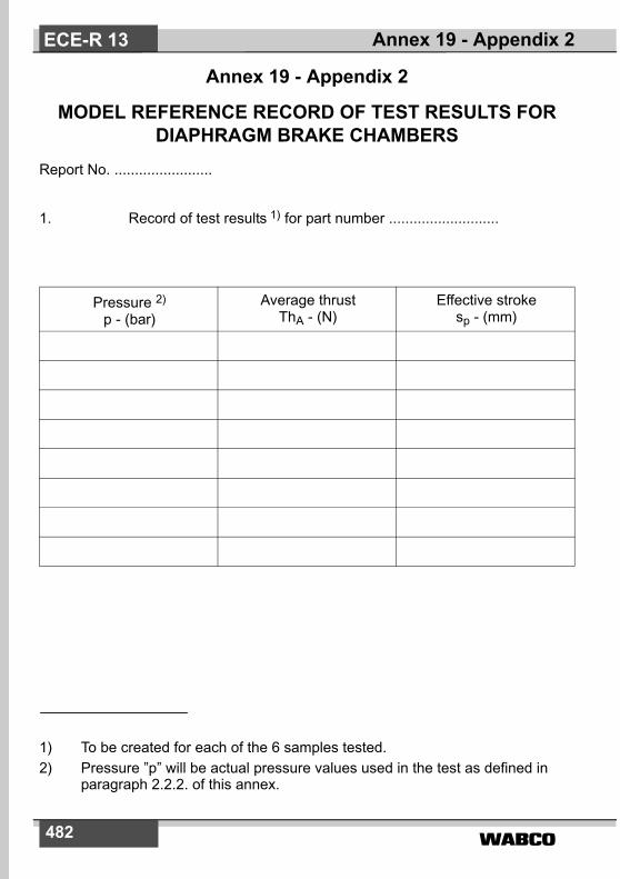
�����482
Annex 19 - Appendix 2
MODEL REFERENCE RECORD OF TEST RESULTS FOR DIAPHRAGM BRAKE CHAMBERS
Report No. ........................
1. Record of test results 1) for part number ...........................
Pressure 2)
p - (bar)Average thrust
ThA - (N)Effective stroke
sp - (mm)
Annex 19 - Appendix 2ECE-R 13
1) To be created for each of the 6 samples tested.2) Pressure ”p” will be actual pressure values used in the test as defined in
paragraph 2.2.2. of this annex.

����� 483
Annex 19 - Appendix 3
MODEL VERIFICATION REPORT FORM FOR SPRING BRAKES
Report No ................................1. Identification:1.1. Manufacturer: (Name and address)
1.2. Make: . . . . . . . . . . . 1)
1.3. Type: . . . . . . . . . . . . 1)
1.4. Part number: . . . . . . 1)
2. Operating conditions:2.1. Maximum working pressure:3. Performance characteristics declared by the manufacturer:
3.1. Maximum stroke (smax) 2)
3.2. Spring thrust (Ths) - f (s) 2)
3.3. Release pressure (at 10 mm stroke) 2)
4. Date of test:5. This test has been carried out and the results reported in accordance
with annex 19 to ECE Regulation No. 13 as last amended by the.... series of amendments.
Technical Service 3) conducting the testSigned : ............... Date: ...............
6. Approval Authority 3) Signed: ................. Date: ...............
7. Test documents:Appendix 4, ................. , .....................,
Annex 19 - Appendix 3 ECE-R 13
1) To be marked on the spring brake, however for inclusion within the testreport only the parent part number is required, model variants need not beindicated.
2) Identification must be amended when changes are made which have aninfluence on the performance characteristics, paragraphs 3.1., 3.2. and 3.3.
3) To be signed by different persons even when the Technical Service andApproval Authority are the same or alternatively, a separate ApprovalAuthority authorisation issued with the report.
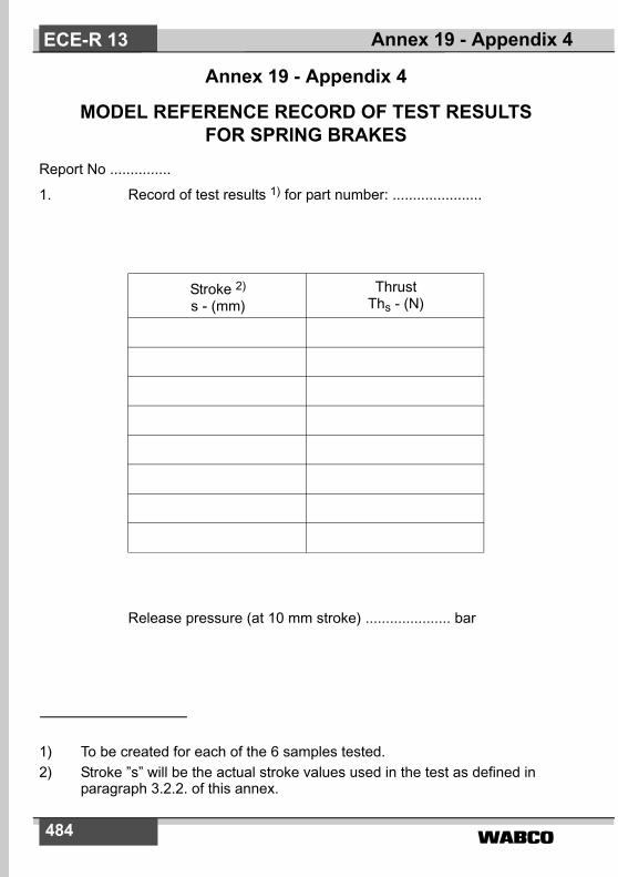
�����484
Annex 19 - Appendix 4
MODEL REFERENCE RECORD OF TEST RESULTS FOR SPRING BRAKES
Report No ...............
1. Record of test results 1) for part number: ......................
Release pressure (at 10 mm stroke) ..................... bar
Stroke 2)
s - (mm)Thrust
Ths - (N)
Annex 19 - Appendix 4ECE-R 13
1) To be created for each of the 6 samples tested.2) Stroke ”s” will be the actual stroke values used in the test as defined in
paragraph 3.2.2. of this annex.

����� 485
Annex 19 - Appendix 5
TRAILER ANTI-LOCK BRAKING SYSTEM INFORMATION DOCUMENT
1. General1.1. Name of manufacturer1.2. System name1.3. System variations1.4. System configurations (e.g. 2S/1M, 2S/2M etc.)1.5. Explanation of the basic function and/or philosophy of the system.
2. Applications2.1. List of trailer types and ABS configurations for which approval is
required.2.2. Schematic diagrams of the system configurations installed on the
trailers defined in item 2.1. above with consideration given to thefollowing parameters:
Sensor locationsModulator locationsLift axlesSteering axlesTube: type - bore size(s) and lengths
2.3. Relationship of tyre circumference to the resolution of the exciter,including tolerances.
2.4. Tolerance of tyre circumference between one axle and another fittedwith the same exciter.
2.5. Scope of application with respect to suspension type e.g. balancedmechanical etc. with reference to the manufacturer and model/type.
2.6. Recommendations on differential brake input torque (if any) inrelation to the ABS configuration and trailer bogie.
2.7. Additional information (if applicable) to the application of the anti-lockbraking system.
Annex 19 - Appendix 5 ECE-R 13
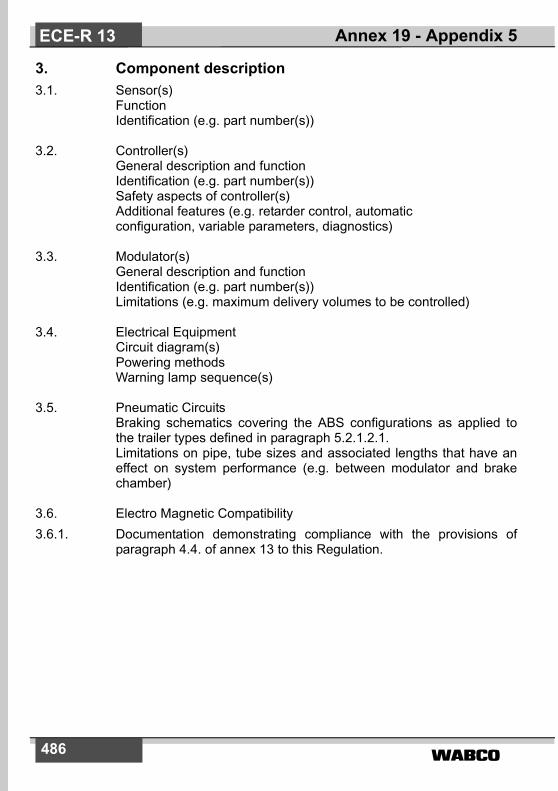
�����486
3. Component description3.1. Sensor(s)
FunctionIdentification (e.g. part number(s))
3.2. Controller(s)General description and functionIdentification (e.g. part number(s))Safety aspects of controller(s)Additional features (e.g. retarder control, automaticconfiguration, variable parameters, diagnostics)
3.3. Modulator(s)General description and functionIdentification (e.g. part number(s))Limitations (e.g. maximum delivery volumes to be controlled)
3.4. Electrical EquipmentCircuit diagram(s)Powering methodsWarning lamp sequence(s)
3.5. Pneumatic CircuitsBraking schematics covering the ABS configurations as applied tothe trailer types defined in paragraph 5.2.1.2.1. Limitations on pipe, tube sizes and associated lengths that have aneffect on system performance (e.g. between modulator and brakechamber)
3.6. Electro Magnetic Compatibility3.6.1. Documentation demonstrating compliance with the provisions of
paragraph 4.4. of annex 13 to this Regulation.
Annex 19 - Appendix 5ECE-R 13

����� 487
Annex 19 - Appendix 6
TRAILER ANTI-LOCK BRAKING SYSTEM TEST REPORTTest Report No: ...................
1. Identification1.1. Manufacturer of the anti-lock braking system (name and address)1.2. System name/model
2. System(s) and Installation(s) approved2.1. ABS configuration(s) approved (e.g. 2S/1M, 2S/2M etc.):2.2. Range of application (type of trailer and number of axles):2.3. Methods of powering: ISO 7638: 1997 , ISO 1185 etc.2.4. Identification of approved sensor(s), controller(s) and modulator(s):2.5. Energy consumption - equivalent number of static brake applications.2.6. Additional features e.g. retarder control, lift axle configuration etc.
3. Test Data and Results3.1. Test vehicle data:3.2. Test surface information:3.3. Test results:3.3.1. Utilisation of adhesion:3.3.2. Energy consumption:3.3.3. Split friction test:3.3.4. Low speed performance:3.3.5. High-speed performance:3.3.6. Additional checks:3.3.6.1. Transition from high to low adhesion surfaces:3.3.6.2. Transition from low to high adhesion surfaces:3.3.7. Failure mode simulation:3.3.8. Functional checks of optional power connections:3.3.9. Electro-magnetic compatibility
Annex 19 - Appendix 6 ECE-R 13
�����488
4. Limits of installation.4.1. Relationship of tyre circumference to the resolution of the exciter:4.2. Tolerance on tyre circumference between one axle and another fitted
with the same exciter:4.3. Suspension type:4.4. Differential(s) in brake input torque within the trailer bogie:4.5. Wheel base of full trailer:4.6. Brake type:4.7. Tube sizes and lengths4.8. Load sensing device application:4.9. Warning lamp sequence:4.10. System configurations and applications that comply with the
category A requirements.4.11. Other recommendations/limitations (e.g. location of sensors,
modulator(s), lift axle(s), steering axle(s)):
5. Date of Test:This test has been carried out and the results reported in accordancewith annex 19 to ECE Regulation No. 13 as last amended by the ..... series of amendments.
Technical Service 1) conducting the test
Signed: ................... Date: ..................
6. Approval Authority 1)
Signed: ................... Date: ..................
Attachment: Manufacturer's information document
Annex 19 - Appendix 6ECE-R 13
1) To be signed by different persons even when the Technical Service andApproval Authority are the same or alternatively, a separate ApprovalAuthority authorisation issued with the report.

����� 489
Annex 19 - Appendix 7
SYMBOLS AND DEFINITIONS
SYMBOL DEFINITION
BF Brake factor (input torque to output torque amplification ratio)
CO Threshold input torque (minimum torque necessary to produce ameasurable brake torque)
D Outer tyre diameter (overall diameter of an inflated new tyre)
d A conventional number denoting the nominal rim diameter and corre-sponding to the diameter of the rim expressed either in inches or mm
FB Brake force
H Nominal tyre section height (the distance equal to half the differencebetween the outer diameter of the tyre and the nominal rim diameter)
I Rotary inertia
lT Brake lever length of reference test trailer
Mt Average brake output torque
ne Equivalent number of static brake applications for the purpose of type approval
ner Equivalent number of static applications obtained during testing
nD Rotational speed of the rolling road
nW Rotational speed of the unbraked wheels of the axle
Pd Maximum technically permitted mass for the brake
p Pressure
R Dynamic tyre rolling radius (calculated using 0.485D)
Ra Nominal aspect ratio of the tyre (one hundred times the number ob-tained by dividing the number expressing the nominal section heightof the tyre in mm by the number expressing the nominal section widthin mm).
Rl Ratio of sT / lT
Annex 19 - Appendix 7 ECE-R 13
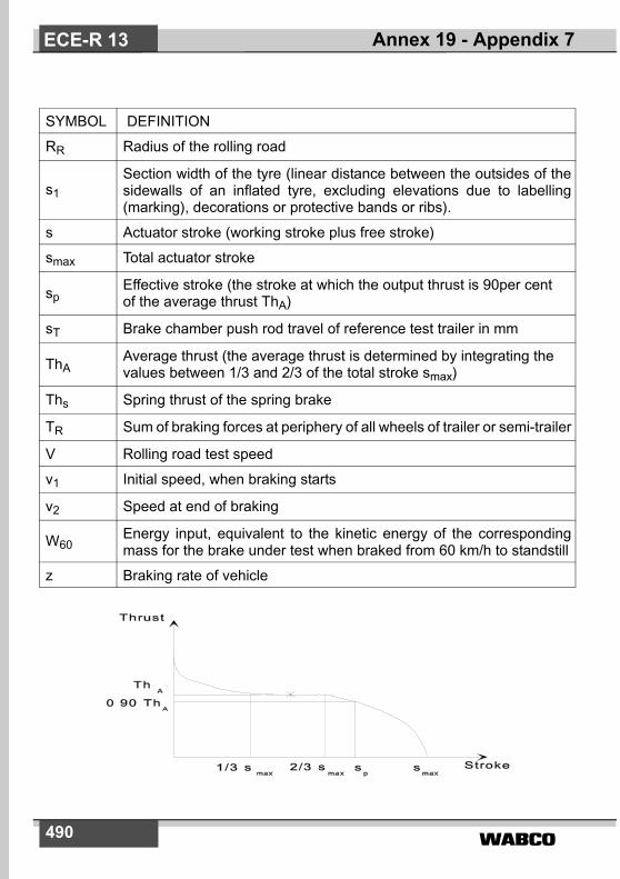
�����490
SYMBOL DEFINITION
RR Radius of the rolling road
s1 Section width of the tyre (linear distance between the outsides of thesidewalls of an inflated tyre, excluding elevations due to labelling(marking), decorations or protective bands or ribs).
s Actuator stroke (working stroke plus free stroke)
smax Total actuator stroke
spEffective stroke (the stroke at which the output thrust is 90per cent of the average thrust ThA)
sT Brake chamber push rod travel of reference test trailer in mm
ThA Average thrust (the average thrust is determined by integrating the values between 1/3 and 2/3 of the total stroke smax)
Ths Spring thrust of the spring brake
TR Sum of braking forces at periphery of all wheels of trailer or semi-trailer
V Rolling road test speed
v1 Initial speed, when braking starts
v2 Speed at end of braking
W60 Energy input, equivalent to the kinetic energy of the correspondingmass for the brake under test when braked from 60 km/h to standstill
z Braking rate of vehicle
Annex 19 - Appendix 7ECE-R 13

����� 491
Annex 20
ALTERNATIVE PROCEDURE FOR THE TYPE APPROVAL OF TRAILERS
1. GeneralThis annex defines an alternative procedure for type approvingtrailers, utilising information from test reports issued in accordancewith annexes 11 and 19.
1.2. On completion of the verification procedures described in paragraphs3., 4., 5., 6., 7. and 8. of this annex, the Technical Service / ApprovalAuthority shall issue an ECE type approval certificate conforming tothe model specified in annex 2, appendix 1 to this Regulation.
1.3. For the purposes of the calculations defined within this annex thecentre of gravity height shall be determined in accordance with themethod defined in appendix 1 to this annex.
2. Application for type approval2.1. The application for ECE type approval of a trailer type with regard to
the braking equipment shall be submitted by the trailer manufacturer.In support of the approval the trailer manufacturer shall supply to theTechnical Service at least the following:
2.1.1. A copy of the ECE or EU Type Approval Certificate and anInformation Document of a trailer hereafter referred to as the”reference trailer” on which the service braking performancecomparison is to be based. This trailer will have been subject to theactual tests defined in annex 4 to this Regulation for the appropriatetrailer or equivalent EU Directive. A trailer that has been approved tothe alternative procedure defined in this annex shall not be used as areference trailer.
2.1.2. Copies of the annex 11 and annex 19 test reports.2.1.3. A documentation package that contains the relevant verification
information including the relevant calculations for the following:
Annex 20 ECE-R 13

492
2.1.4. A trailer, representative of the trailer type to be approved hereafterreferred to as the ”subject trailer”.
2.2. The manufacturer of the ”reference trailer” and ”subject trailer” shallbe the same.
3. Alternative procedure for demonstrating the Type-0 service braking cold performance.
3.1. To demonstrate compliance with the Type-0 service braking coldperformance it shall be verified, by calculation, that the ”subjecttrailer” has sufficient brake force (TR) available to achieve theprescribed service braking performance and that there is sufficientadhesion available on a dry road surface (assumed to have acoefficient of adhesion of 0.8) to utilise this brake force.
3.2. Verification.3.2.1. The requirements of annex 4, paragraph 1.2.7. and 3.1.2. (cold
performance requirement and achievement without wheel lock,deviation or abnormal vibration) are considered to be satisfied by thesubject trailer if it meets the verification criteria described in thefollowing paragraphs, in both the laden and unladen conditions:
3.2.1.1. The wheelbase of the subject trailer shall not be less than 0.8 timesthe reference trailer wheelbase.
3.2.1.2. Any difference in the brake input torque between one axle andanother within a bogie of the ”subject trailer” shall not differ from thatof the ”reference trailer”.
3.2.1.3. The number and arrangement of axles i.e. lifting, steering etc. of the”subject trailer” shall not differ from that of the reference trailer.
Performance Requirements Annex 20 reference
Cold service braking performance 3.0
Parking brake performance 4.0
Emergency brake performance 5.0
Failure of brake distribution system 6.0
Anti-lock braking system 7.0
Annex 20ECE-R 13

493
3.2.1.4. The percentage distribution of the laden static axle load of the subjecttrailer shall not differ from that of the reference trailer by more than 10per cent.
3.2.1.5. For semi trailers, a graph, in accordance with appendix 2, shall beconstructed and, from this graph, it shall be verified that:
TR max ≥ TRpr (i.e. line (1) shall not be below line (3)), and
TRL ≥ TRpr (i.e. line (2) shall not be below line (3)).
3.2.1.6. For centre axle trailers, a graph, in accordance with appendix 3, shallbe constructed and, from this graph, it shall be verified that:
TR max ≥ TRpr (i.e. line (1) shall not be below line (3)), and
TRL ≥ TRpr (i.e. line (2) shall not be below line (3)).
3.2.1.7. For full trailers, a graph, in accordance with appendix 4, shall beconstructed and, from this graph, it shall be verified that:
TR max ≥ TRpr (i.e. line (1) shall not be below line (2)), and
TRLf ≥ TRprf (i.e. line (4) shall not be below line (3)), and
TRLr ≥ TRprr (i.e. line (6) shall not be below line (5)).
4. Alternative procedure for demonstrating the parking brake performance.
4.1. General4.1.1. This procedure provides an alternative to physically testing trailers on
a gradient and ensures that trailers fitted with spring brake actuatedparking mechanisms can meet the prescribed parking brakeperformance. This procedure shall not be applied to trailers fitted withparking mechanisms operated by means other than spring brakes.Such trailers shall be subjected to the physical test prescribed inannex 4.
4.1.2. The prescribed parking braking performance shall be demonstratedby calculation, using the formulae contained in paragraphs 4.2. and4.3.
Annex 20 ECE-R 13
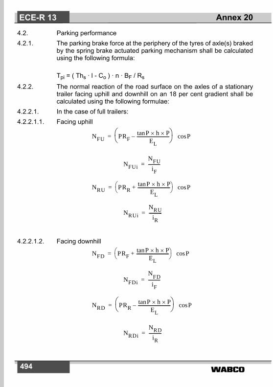
�����494
4.2. Parking performance4.2.1. The parking brake force at the periphery of the tyres of axle(s) braked
by the spring brake actuated parking mechanism shall be calculatedusing the following formula:
Tpi = ( Ths · l - Co ) · n · BF / Rs
4.2.2. The normal reaction of the road surface on the axles of a stationarytrailer facing uphill and downhill on an 18 per cent gradient shall becalculated using the following formulae:
4.2.2.1. In the case of full trailers:4.2.2.1.1. Facing uphill
4.2.2.1.2. Facing downhill
NFU PRFPtan h P��
EL------------------------------–� �
� �= Pcos
NFUi
NFUiF
-----------=
NRU PRRPtan h P��
EL------------------------------+� �
� �= Pcos
NRUi
NRUiR
------------=
NFD PRFPtan h P��
EL------------------------------+� �
� �= Pcos
NFDi
NFDiF
-----------=
NRD PRRPtan h P��
EL------------------------------–� �
� �= Pcos
NRDi
NRDiR
------------=
Annex 20ECE-R 13

����� 495
4.2.2.2. In the case of centre axle trailers:4.2.2.1. Facing uphill
4.2.2.2.2. Facing downhill
4.2.2.3. In the case of semi-trailers:4.2.2.3.1. Facing uphill
4.2.2.3.2. Facing downhill
4.3. Verification4.3.1. The parking brake performance of the trailer shall be verified using
the following formulae:
NRU P Ptan h P��EL
------------------------------+� �� �= Pcos
NRUi
NRUiR
------------=
NRD P Ptan h P��EL
------------------------------–� �� �= Pcos
NRDi
NRDiR
------------=
NRU PPs ER�
EL------------------- Ptan h P��
EL------------------------------+–
� �� �� �
= Pcos
NRUi
NRUiR
------------=
NRD PPs ER�
EL-------------------– Ptan h� P�
EL------------------------------–
� �� �� �
= Pcos
NRDi
NRDiR
------------=
Annex 20 ECE-R 13

�����496
x 100 � 18%
and:
x 100 � 18%
5. Alternative procedure for demonstrating the emergency/automatic braking performance
5.1. General5.1.1. To demonstrate compliance with the automatic braking performance
requirements, either a comparison is made between the chamberpressure required to achieve the specified performance and theasymptotic chamber pressure after disconnection of the supply line,as defined in paragraph 5.2.1., or it shall be verified that the brakeforce provided by the axle(s) fitted with spring brakes is sufficient toachieve the specified performance, as defined in paragraph 5.2.2.
5.2. Verification5.2.1. The requirements of annex 4, paragraph 3.3., are considered to be
satisfied by a subject trailer if the asymptotic chamber pressure (pc)after disconnection of the supply line is greater than the chamberpressure (pc) to achieve a performance of 13.5 per cent of themaximum stationary wheel load. The supply line pressure beingstabilised at 7.0 bar prior to disconnection.
5.2.2. The requirements of annex 4, paragraph 3.3., are considered to besatisfied by a spring brake equipped subject trailer if:
� Tpi � 0.135 · PR · g
where Tpi is calculated in accordance with paragraph 4.2.1.
6. Alternative procedure for demonstrating braking performance in the case of failure of the braking distribution system
6.1. General
�ADi �BDi+P
--------------------------------- 0 01,+� �� �
�AUi �BU i+
P--------------------------------- 0 01,+� �� �
Annex 20ECE-R 13
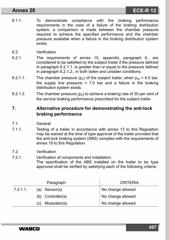
����� 497
6.1.1. To demonstrate compliance with the braking performancerequirements in the case of a failure of the braking distributionsystem, a comparison is made between the chamber pressurerequired to achieve the specified performance and the chamberpressure available when a failure in the braking distribution systemexists.
6.2. Verification6.2.1. The requirements of annex 10, appendix, paragraph 6., are
considered to be satisfied by the subject trailer if the pressure definedin paragraph 6.2.1.1. is greater than or equal to the pressure definedin paragraph 6.2.1.2., in both laden and unladen conditions.
6.2.1.1. The chamber pressure (pc) of the subject trailer, when pm = 6.5 bar,the supply line pressure = 7.0 bar and a failure in the brakingdistribution system exists.
6.2.1.2. The chamber pressure (pc) to achieve a braking rate of 30 per cent ofthe service braking performance prescribed for the subject trailer.
7. Alternative procedure for demonstrating the anti-lock braking performance
7.1. General7.1.1. Testing of a trailer in accordance with annex 13 to this Regulation
may be waived at the time of type approval of the trailer provided thatthe anti-lock braking system (ABS) complies with the requirements ofannex 19 to this Regulation.
7.2. Verification7.2.1. Verification of components and installation.
The specification of the ABS installed on the trailer to be typeapproved shall be verified by satisfying each of the following criteria:
Paragraph CRITERIA
7.2.1.1. (a) Sensor(s)
(b) Controller(s)
(c) Modulator(s)
No change allowed
No change allowed
No change allowed
Annex 20 ECE-R 13

�����498
7.3. Verification of reservoir capacity7.3.1. As the range of braking systems and auxiliary equipment used on
trailers is diverse it is not possible to have a table of recommendedreservoir capacities. To verify that adequate storage capacity isinstalled, testing may be conducted according to paragraph 6.1. ofannex 13 to this Regulation or by the procedure defined below:
7.3.1.1. In the case of brakes with non integrated brake wear adjustment thebrakes on the subject trailer shall be set to a condition where therelationship (R1) of brake chamber push rod travel (sT) against leverlength (lT) is 0.2.
Example:lt = 130 mm
Re = sT / lT = sT / 130 = 0.2
sT = Push rod travel at 6.5 bar brake chamber pressure
= 130 x 0.2 = 26 mm7.3.1.2. In the case of brakes with integrated automatic brake wear
adjustment the brakes shall be set to a normal running clearance.
7.2.1.2. Tube size(s) and lengths
(a) Reservoir supply to modulator(s)
Minimum inside diameter May be increased
Maximum overall length
(b) Modulator delivery to brake chambers
Inside diameter
Maximum overall length
May be reduced
No change allowed
May be reduced
7.2.1.3. Warning signal sequence No change allowed
7.2.1.4. Differentials in brake inputtorque within a bogie
Only approved differentials (if any) permitted
7.2.1.5. For other limitations refer toparagraph 4. of the test report asdescribed in appendix 6 of annex19 to this Regulation
Installation to be within the scope of the limitationsdefined - No deviations allowed
Annex 20ECE-R 13
����� 499
7.3.1.3. Setting of the brakes as defined above shall be carried out when thebrakes are cold (� 100 °C).
7.3.1.4. With the brakes adjusted according to relevant procedure definedabove and the load sensing device(s) set to the laden condition andthe initial energy level set according to paragraph 6.1.2. of annex 13to this Regulation, the energy storage device(s) shall be isolated fromfurther supply. The brakes shall be applied with a control pressure of6.5 bar at the coupling head and then fully released. Further brakeapplications shall be made up to the number to be determined fromthe test conducted in accordance with paragraph 5.4.1.2.4.2. ofannex 19 to this Regulation and defined in paragraph 2.5. of the anti-lock braking system Approval Report. During this application, thepressure in the operating circuit shall be sufficient to provide a totalbraking force at the periphery of the wheels equal to not less than22.5 per cent of the maximum stationary wheel load and withoutcausing automatic application of any braking system not under thecontrol of the anti-lock braking system.
8. Functional and installation checks8.1. The Technical Service / Approval Authority shall carry out functional
and installation checks covering the following paragraphs:8.1.1. Anti-lock function8.1.1.1. This shall be limited to a dynamic check of the anti-lock braking
system. To ensure full cycling it may be necessary to adjust the loadsensing device or utilise a surface having a low tyre to road adhesion.If the anti-lock braking system does not have an annex 19 approval,the trailer shall be tested in accordance with annex 13 and complywith the relevant requirements contained in that annex.
8.1.2. Response time measurement8.1.2.1. The Technical Service shall verify that the subject trailer conforms to
the requirements of annex 6.8.1.3. Static energy consumption8.1.3.1. The Technical Service shall verify that the subject trailer conforms to
the requirements of annex 7 and annex 8 as appropriate.8.1.4. Service brake function8.1.4.1. The Technical Service shall verify that there are no abnormal
vibrations during braking.8.1.5. Parking brake function
Annex 20 ECE-R 13

�����500
8.1.5.1. The Technical Service shall apply and release the park brake toensure correct function.
8.1.6. Emergency/automatic braking function8.1.6.1. The Technical Service shall verify that the subject trailer complies
with the requirements of paragraph 5.2.1.18.4.2. of this Regulation8.1.7. Vehicle and component identification verification8.1.7.1. The Technical Service shall check the subject trailer against the
details contained in the type approval certificate.8.1.8. Additional checks8.1.8.1. The Technical Service may request additional checks to be carried
out, if necessary.
Annex 20ECE-R 13

����� 501
Annex 20 - Appendix 1
METHOD OF CALCULATING THE CENTRE OF GRAVITY HEIGHT
The centre of gravity height for the complete vehicle (laden and unladen) can be cal-culated as follows:h1 = centre of gravity height of axle(s) assembly (inc. tyres, springs, etc.)
= R · 1.1
h2 = centre of gravity height of frame (laden) = (h6 + h8) · 0.5
h3 = centre of gravity height of payload and bodywork (laden)
= (h7 · 0.3) + h6
h4 = centre of gravity height of frame (unladen) = h2 + s
h5 = centre of gravity height of bodywork (unladen) = (h7 · 0.5) + h6 + s
where:
h6 = frame height, top
h7 = body dimensions, inside
h8 = frame height, bottom
P = total mass of the trailer
PR = total mass on all wheels of a semi trailer or centre axle trailer
R = radius of the tyre
s = spring deflection between laden and unladen
W1 = mass of axle(s) assembly (inc. tyres, springs, etc.) = P · 0.1
W2 = mass of the frame = (Punl - W1) · 0.8
W3 = mass of payload and bodywork
W4 = mass of bodywork = (Punl - W1) · 0.2
Annex 20 - Appendix 1 ECE-R 13

�����502
LADEN: UNLADEN:
NOTES:(1) For flat bed type trailers, a maximum height of 4 m shall be used.
(2) For trailers where the exact centre of gravity height of the payload is not known,it shall be taken as 0.3 times the inside dimensions of the body.
(3) For trailers with air suspension, the value of s shall be taken as zero.
(4) For semi-trailers and centre axle trailers, replace P with PR wherever it occurs.
hRladh1 W1 h2 W2 h3 W3�+�+�
Plad--------------------------------------------------------= hRunl
h1 W1 h4 W2 h5 W4�+�+�Punl
--------------------------------------------------------=
Annex 20 - Appendix 1ECE-R 13

503
Annex 20 - Appendix 2
VERIFICATION GRAPH FOR PARAGRAPH 3.2.1.5. - SEMI TRAILERS
(1) = TRmax , when pm = 6.5 bar and supply line = 7.0 bar.
(2) = FRdyn · 0.8 = TRL
(3) = 0.45· FR = TRpr
where:
the value of zc being calculated using the following formula:
NOTES:(1) The value of 7,000 above represents the mass of a towing vehicle with no
trailer attached.(2) For the purpose of these calculations, closely spaced axles (having an axle
spread of less than 2 metres) may be treated as one axle.
FRdyn FRTRpr( hk ) P( g zc hR( hk ) )–⋅××+×
ER---------------------------------------------------------------------------------------–=
zc 0 45, 0 01,FR
P( 7000 )+ g⋅--------------------------------
0 01,+⋅ ⋅=
Annex 20 - Appendix 2 ECE-R 13

504
Annex 20 - Appendix 3
VERIFICATION GRAPH FOR PARAGRAPH 3.2.1.6 - CENTRE AXLE TRAILERS
(1) = TRmax , when pm = 6.5 bar and supply line = 7.0 bar.(2) = FRdyn · 0.8 = TRL
(3) = 0.5 · FR = TRpr
where:
the value of zc being calculated using the following formula:
NOTES:(1) The value of 7,000 above represents the mass of a towing vehicle with no
trailer attached.(2) For the purpose of these calculations, closely spaced axles (having an axle
spread of less than 2 metres) may be treated as one axle.
FRdyn FRTRpr( hk ) P( g zc hR( hk ) )–⋅××+×
ER---------------------------------------------------------------------------------------–=
zc 0 5, 0 01,–FR
P( 7000 )+ g⋅--------------------------------
0 01,+⋅=
Annex 20 - Appendix 3ECE-R 13
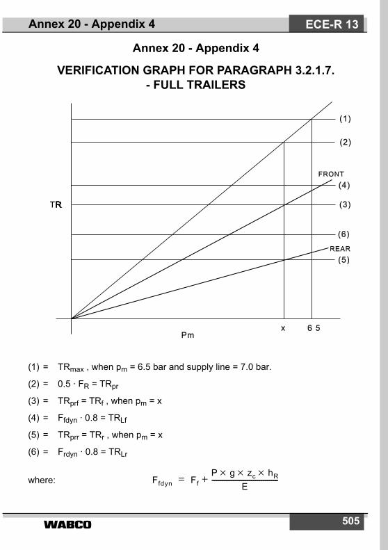
505
Annex 20 - Appendix 4
VERIFICATION GRAPH FOR PARAGRAPH 3.2.1.7. - FULL TRAILERS
(1) = TRmax , when pm = 6.5 bar and supply line = 7.0 bar.
(2) = 0.5 · FR = TRpr
(3) = TRprf = TRf , when pm = x
(4) = Ffdyn · 0.8 = TRLf
(5) = TRprr = TRr , when pm = x
(6) = Frdyn · 0.8 = TRLr
where: Ffdyn FfP g zc hR×××
E----------------------------------+=
Annex 20 - Appendix 4 ECE-R 13
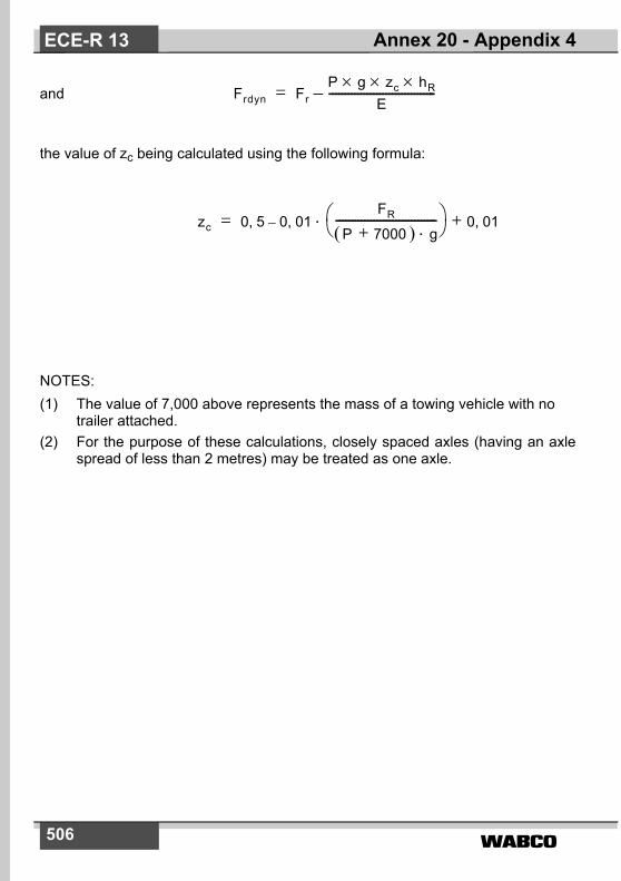
506
and
the value of zc being calculated using the following formula:
NOTES:(1) The value of 7,000 above represents the mass of a towing vehicle with no
trailer attached.(2) For the purpose of these calculations, closely spaced axles (having an axle
spread of less than 2 metres) may be treated as one axle.
Frdyn FrP g zc hR×××
E----------------------------------–=
zc 0 5, 0 01,–FR
P( 7000 )+ g⋅--------------------------------
0 01,+⋅=
Annex 20 - Appendix 4ECE-R 13
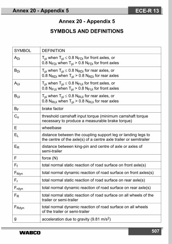
507
Annex 20 - Appendix 5
SYMBOLS AND DEFINITIONS
SYMBOL DEFINITION
ADi Tpi when Tpi ≤ 0.8 NFDi for front axles, or 0.8 NFDi when Tpi > 0.8 NFDi for front axles
BDi Tpi when Tpi ≤ 0.8 NRDi for rear axles, or 0.8 NRDi when Tpi > 0.8 NRDi for rear axles
AUi Tpi when Tpi ≤ 0.8 NFUi for front axles, or 0.8 NFUi when Tpi > 0.8 NFUi for front axles
BUi Tpi when Tpi ≤ 0.8 NRUi for rear axles, or 0.8 NRUi when Tpi > 0.8 NRUi for rear axles
BF brake factor
Co threshold camshaft input torque (minimum camshaft torque necessary to produce a measurable brake torque)
E wheelbase
EL distance between the coupling support leg or landing legs to the centre of the axle(s) of a centre axle trailer or semitrailer
ER distance between king-pin and centre of axle or axles of semi-trailer
F force (N)
Ff total normal static reaction of road surface on front axle(s)
Ffdyn total normal dynamic reaction of road surface on front axles(s)
Fr total normal static reaction of road surface on rear axle(s)
Frdyn total normal dynamic reaction of road surface on rear axle(s)
FR total normal static reaction of road surface on all wheels of the trailer or semi-trailer
FRdyn total normal dynamic reaction of road surface on all wheels of the trailer or semi-trailer
g acceleration due to gravity (9.81 m/s2)
Annex 20 - Appendix 5 ECE-R 13
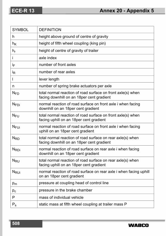
�����508
SYMBOL DEFINITION
h height above ground of centre of gravity
hK height of fifth wheel coupling (king pin)
hr height of centre of gravity of trailer
i axle index
iF number of front axles
iR number of rear axles
l lever length
n number of spring brake actuators per axle
NFD total normal reaction of road surface on front axle(s) when facing downhill on an 18per cent gradient
NFDi normal reaction of road surface on front axle i when facing downhill on an 18per cent gradient
NFU total normal reaction of road surface on front axle(s) when facing uphill on an 18per cent gradient
NFUi normal reaction of road surface on front axle i when facing uphill on an 18per cent gradient
NRD total normal reaction of road surface on rear axle(s) when facing downhill on an 18per cent gradient
NRDi normal reaction of road surface on rear axle i when facing downhill on an 18per cent gradient
NRU total normal reaction of road surface on rear axle(s) when facing uphill on an 18per cent gradient
NRUi normal reaction of road surface on rear axle i when facing uphill on an 18per cent gradient
pm pressure at coupling head of control line
pc pressure in the brake chamber
P mass of individual vehicle
Ps static mass at fifth wheel coupling at trailer mass P
Annex 20 - Appendix 5ECE-R 13
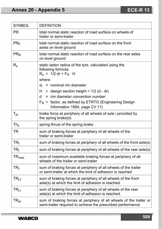
����� 509
SYMBOL DEFINITION
PR total normal static reaction of road surface on wheels of trailer or semi-trailer
PRF total normal static reaction of road surface on the front axles on level ground
PRR total normal static reaction of road surface on the rear axles on level ground
Rs static laden radius of the tyre, calculated using the following formula:Rs = 1/2 dr + FR · Hwhere:dr = nominal rim diameterH = design section height = 1/2 (d - dr)d = rim diameter convention numberFR = factor, as defined by ETRTO (Engineering Design
Information 1994, page CV.11)
Tpi brake force at periphery of all wheels of axle i provided by the spring brake(s)
Ths spring thrust of the spring brake
TR sum of braking forces at periphery of all wheels of the trailer or semi-trailer
TRf sum of braking forces at periphery of all wheels of the front axle(s)
TRr sum of braking forces at periphery of all wheels of the rear axle(s)
TRmax sum of maximum available braking forces at periphery of allwheels of the trailer or semi-trailer
TRL sum of braking forces at periphery of all wheels of the trailer or semi-trailer at which the limit of adhesion is reached
TRLf sum of braking forces at periphery of all wheels of the front axle(s) at which the limit of adhesion is reached
TRLr sum of braking forces at periphery of all wheels of the rear axle(s) at which the limit of adhesion is reached.
TRpr sum of braking forces at periphery of all wheels of the trailer orsemi-trailer required to achieve the prescribed performance
Annex 20 - Appendix 5 ECE-R 13

�����510
SYMBOL DEFINITION
TRprf sum of braking forces at periphery of all wheels of the front axle(s) required to achieve the prescribed performance
TRprr sum of braking forces at periphery of all wheels of the rear axle(s) required to achieve the prescribed performance
zc braking rate of the vehicle combination, with the trailer only braked
cos P cosine of angle subtended by slope of 18per cent and horizontal plane = 0.98418
tan P tangent of angle subtended by slop of 18per cent and horizontal plane = 0.18
Annex 20 - Appendix 5ECE-R 13