
ECE 4853: Optical Fiber Communication Waveguide/Fiber Modes (Slides and figures courtesy of Saleh &...
45
ECE 4853: Optical Fiber Communication Waveguide/Fiber Modes (Slides and figures courtesy of Saleh & Teich) (Modified, amended and adapted by R. Winton) From the movie Warriors of the Net
-
Upload
kenneth-dawson -
Category
Documents
-
view
224 -
download
0
Transcript of ECE 4853: Optical Fiber Communication Waveguide/Fiber Modes (Slides and figures courtesy of Saleh &...
ECE 4853: Optical Fiber Communication Waveguide/Fiber Modes
(Slides and figures courtesy of Saleh & Teich)(Modified, amended and adapted by R. Winton)
From the movieWarriors of the Net
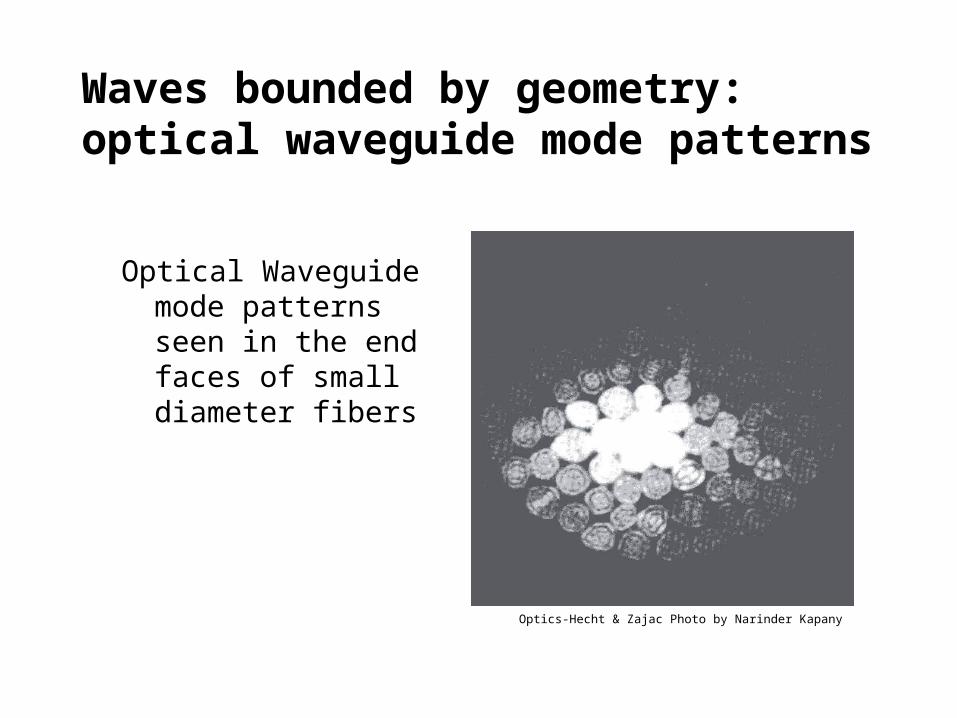
Waves bounded by geometry: optical waveguide mode patterns
Optical Waveguide mode patterns seen in the end faces of small diameter fibers
Optics-Hecht & Zajac Photo by Narinder Kapany
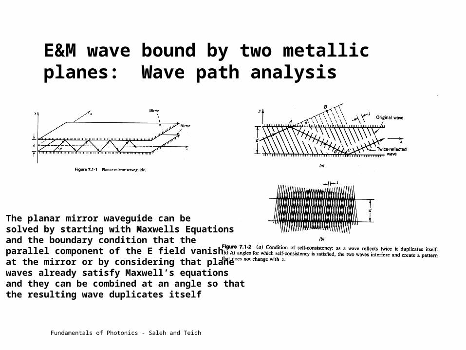
E&M wave bound by two metallic planes: Wave path analysis
The planar mirror waveguide can be solved by starting with Maxwells Equationsand the boundary condition that the parallel component of the E field vanishat the mirror or by considering that plane waves already satisfy Maxwell’s equationsand they can be combined at an angle so thatthe resulting wave duplicates itself
Fundamentals of Photonics - Saleh and Teich

Mode number and wave context (metallic reflections)
Fundamentals of Photonics - Saleh and Teich
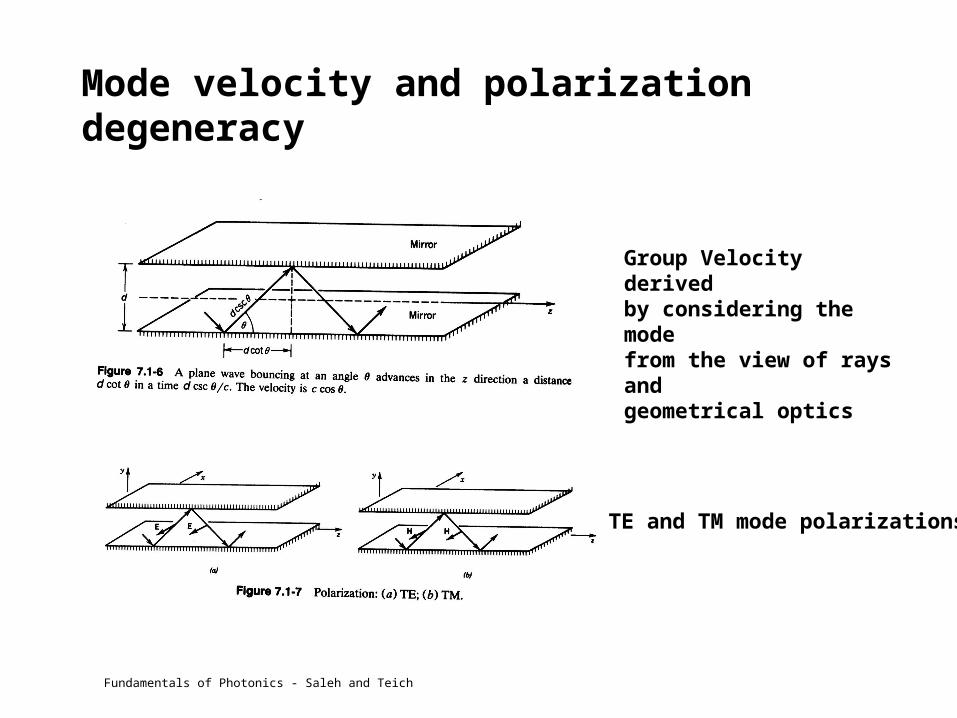
Mode velocity and polarization degeneracy
Group Velocity derivedby considering the modefrom the view of rays and geometrical optics
TE and TM mode polarizations
Fundamentals of Photonics - Saleh and Teich

Planar slab dielectric wave guide
Characteristic equation and self-consistency condition for identifying allowed values of m
Geometry of planar dielectric guide
Fundamentals of Photonics - Saleh and Teich
(Characteristic equation = consequence of either geometrical or E&M wave propagation analysis)

Planar slab dielectric wave guide modes
Propagation Constants
Number of modes vs frequency
The m must be between that expected for a plane wave in the core and that expected for a plane wave in the cladding
Note: For a sufficiently low frequency only 1 mode can propagate
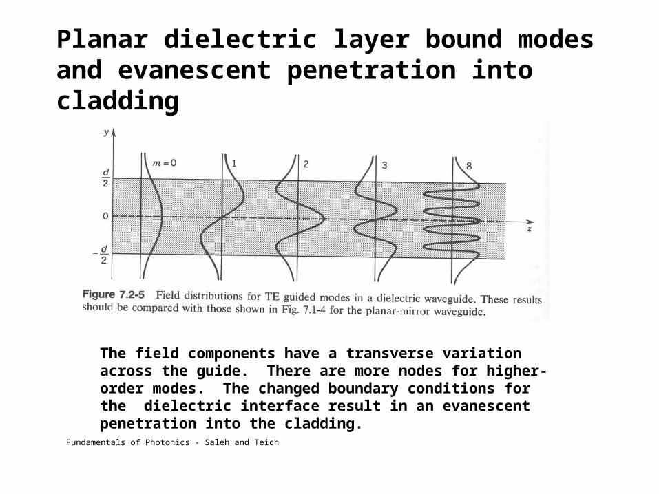
Planar dielectric layer bound modes and evanescent penetration into cladding
The field components have a transverse variation across the guide. There are more nodes for higher-order modes. The changed boundary conditions for the dielectric interface result in an evanescent penetration into the cladding.
Fundamentals of Photonics - Saleh and Teich
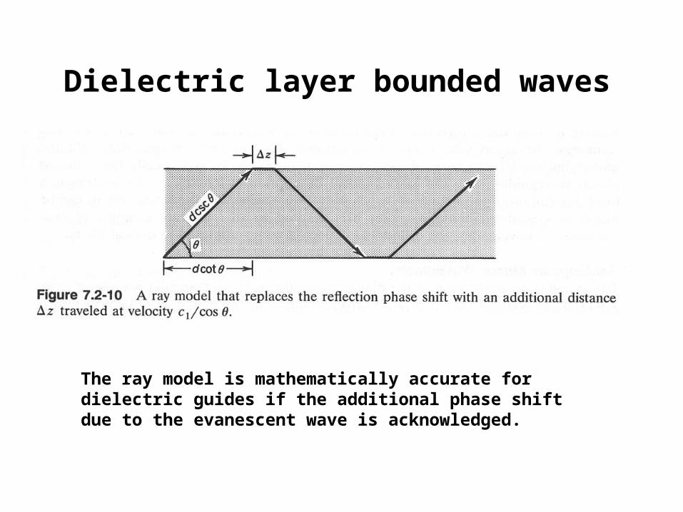
Dielectric layer bounded waves
The ray model is mathematically accurate for dielectric guides if the additional phase shift due to the evanescent wave is acknowledged.

Waveguides obey Maxwell equations, which for simple, isotropic dielectric material with no free charges are:
(Faraday law, Gauss law)
(Ampere law, Gauss law)

And the relationships between field types (for simple, isotropic dielectric material with no free charges) are:
And if we put all of these equations together (vector analysis) we end up with the wave equation:
which is the same for the magnetic field:

The rectangular cross-section has the simplest mathematics. The wave equation in rectangular coordinates is
Which, using becomes
or
or (simpler)
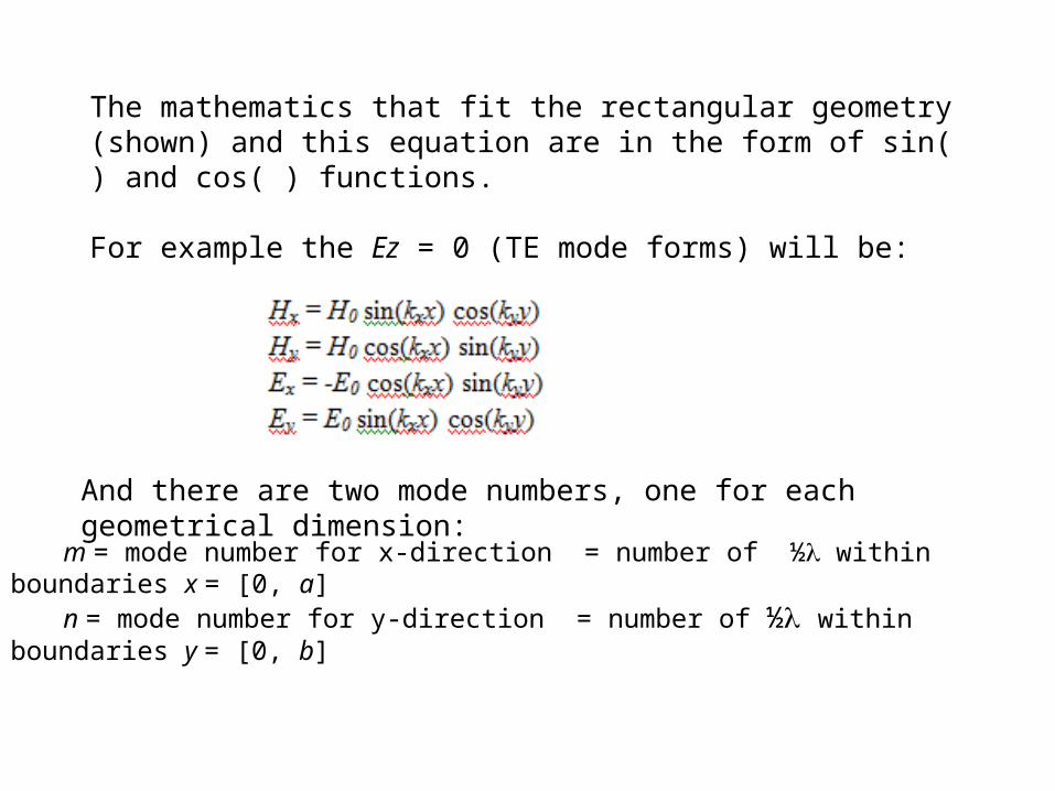
The mathematics that fit the rectangular geometry (shown) and this equation are in the form of sin( ) and cos( ) functions.
For example the Ez = 0 (TE mode forms) will be:
And there are two mode numbers, one for each geometrical dimension:
m = mode number for x-direction = number of ½ within boundaries x = [0, a]n = mode number for y-direction = number of ½ within boundaries y = [0, b]

Typical end-view representations of some of these modes

Two Dimensional Rectangular Planar Guide
In two dimensions the transverse field depends on both kx and ky and the number of modes goes as the square of d/
The number of modes is limited by the maximum angle c that can propagate
Fundamentals of Photonics - Saleh and Teich
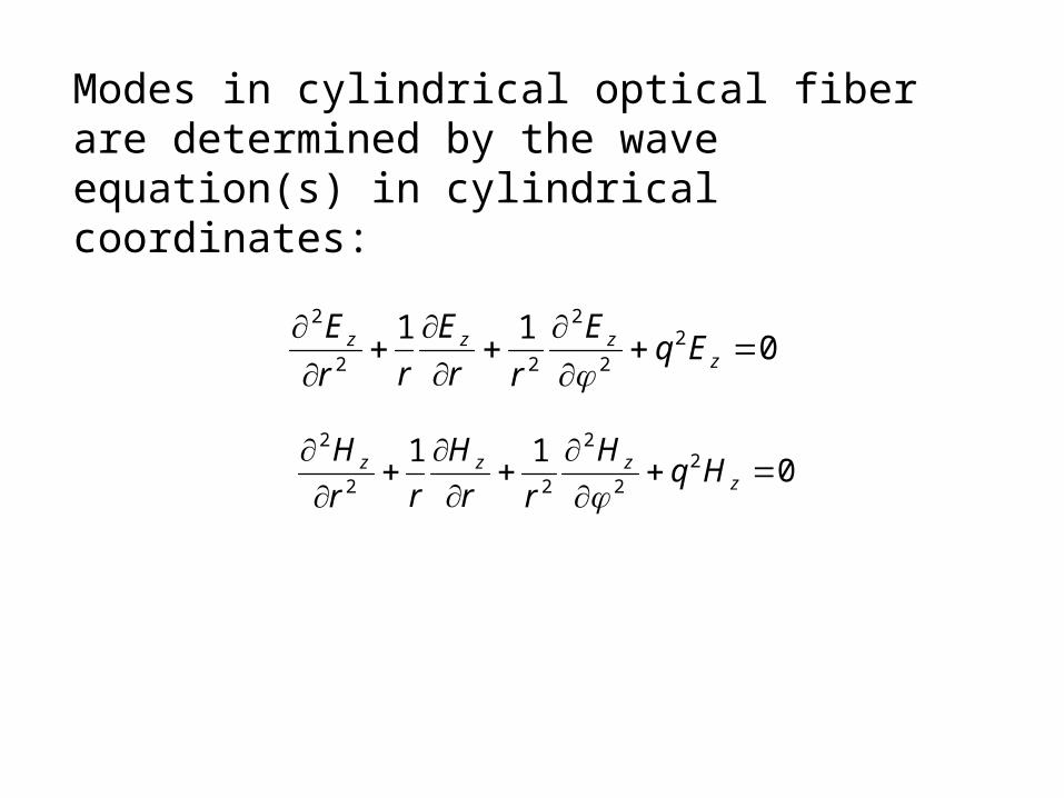
Modes in cylindrical optical fiber are determined by the wave equation(s) in cylindrical coordinates:
011 2
2
2
22
2
zzzz EqE
rr
E
rr
E
011 2
2
2
22
2
zzzz Hq
H
rr
H
rr
H
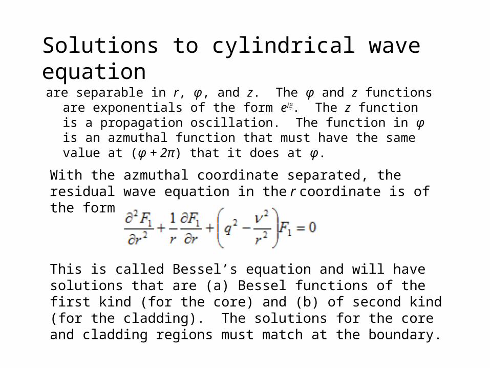
Solutions to cylindrical wave equation
are separable in r, φ, and z. The φ and z functions are exponentials of the form ei. The z function is a propagation oscillation. The function in φ is an azmuthal function that must have the same value at (φ + 2π) that it does at φ.
This is called Bessel’s equation and will have solutions that are (a) Bessel functions of the first kind (for the core) and (b) of second kind (for the cladding). The solutions for the core and cladding regions must match at the boundary.
With the azmuthal coordinate separated, the residual wave equation in the r coordinate is of the form
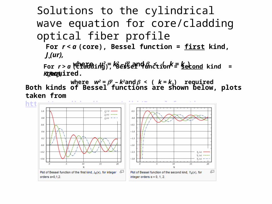
Solutions to the cylindrical wave equation for core/cladding optical fiber profile
Both kinds of Bessel functions are shown below, plots taken from http://en.wikipedia.org/wiki/Bessel_function
For r < a (core), Bessel function = first kind, J(ur), where u2 = k2 –2 and < ( k = k1) required.
For r > a (cladding), Bessel function = second kind = K(wr), where w2 = 2 – k2and < ( k = k2) required
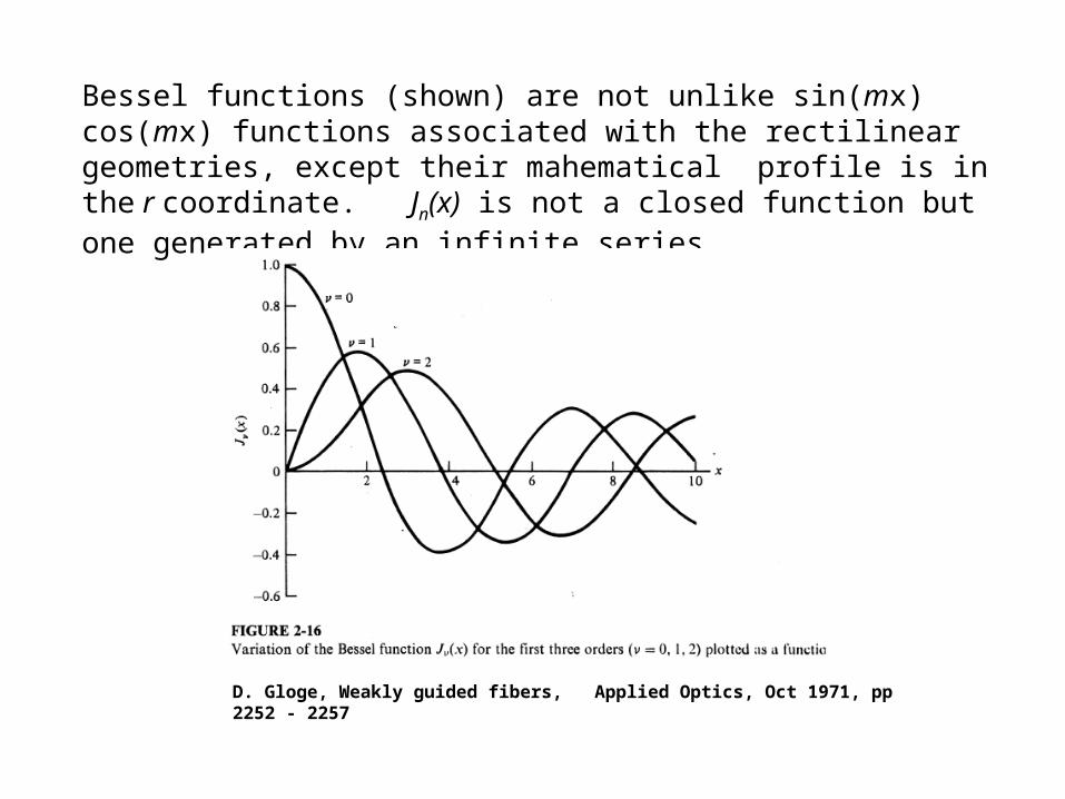
Bessel functions (shown) are not unlike sin(mx) cos(mx) functions associated with the rectilinear geometries, except their mahematical profile is in the r coordinate. Jn(x) is not a closed function but one generated by an infinite series.
D. Gloge, Weakly guided fibers, Applied Optics, Oct 1971, pp 2252 - 2257

Step index cylindrical waveguide: Bessel function boundary matching
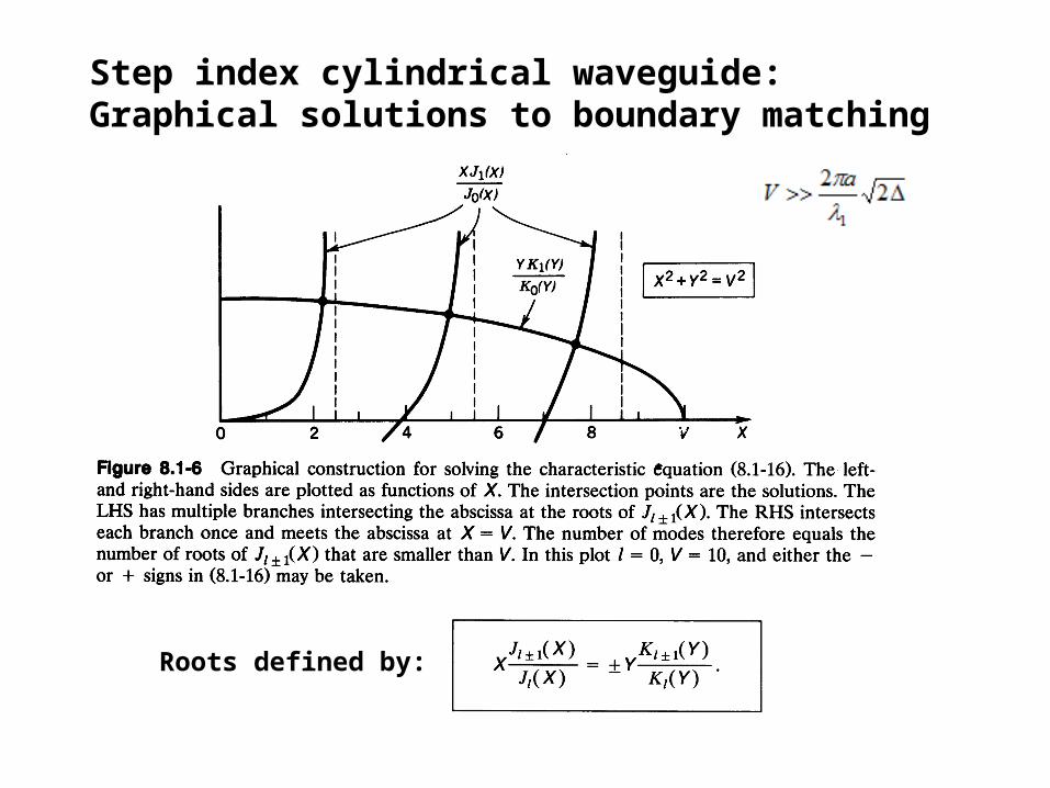
Step index cylindrical waveguide: Graphical solutions to boundary matching
Roots defined by:

Defining parameters for cylindrical functions
• For the Bessel equation q2 = ω2εμ – β2 = k2 – β2.
q2 is defined as u2 for r < a. q2 is defined as -w2 for r > a.
• β = Z is the z component of the propagation constant k = 2π/λ. The boundary conditions for the Bessel equations can be solved only for certain values of β, so only certain modes exist.
• A mode is guided if (n2k = k2) < β < (k2 = n2k) where n1, n2 = refractive indices of core and cladding, respectively.
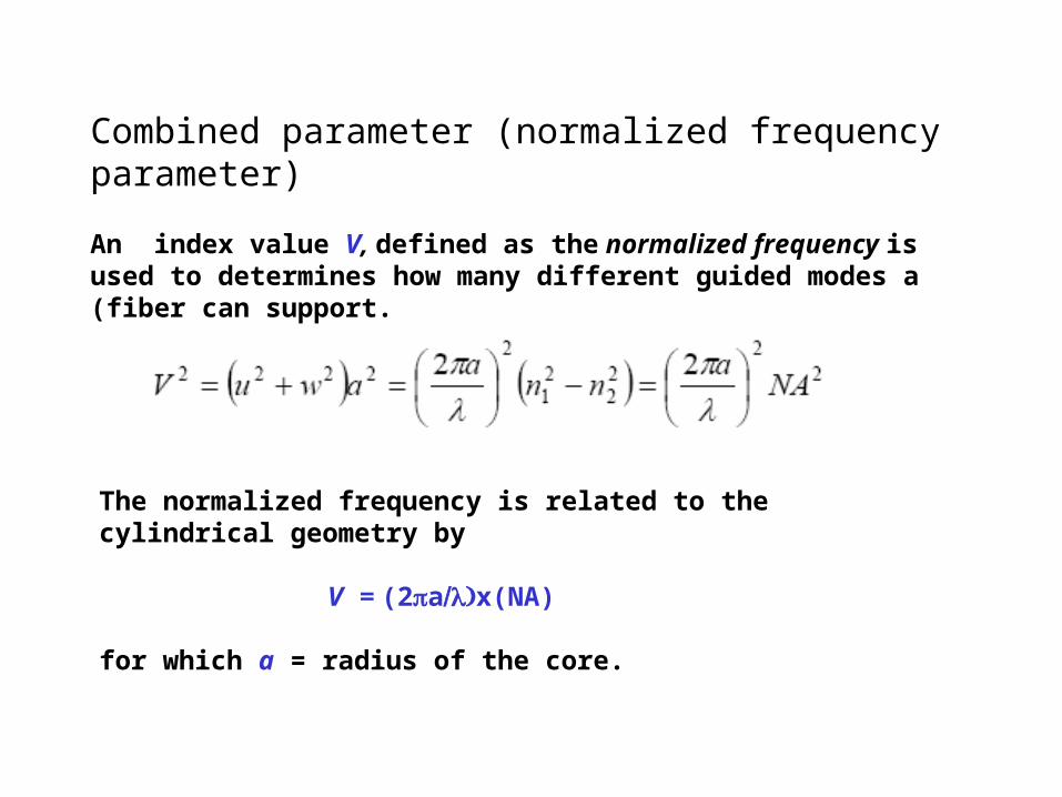
Combined parameter (normalized frequency parameter)
An index value V, defined as the normalized frequency is used to determines how many different guided modes a (fiber can support.
The normalized frequency is related to the cylindrical geometry by
V = (2ax(NA)
for which a = radius of the core.
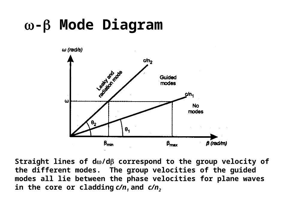
- Mode Diagram
Straight lines of d/d correspond to the group velocity of the different modes. The group velocities of the guided modes all lie between the phase velocities for plane waves in the core or cladding c/n1 and c/n2
Types of cylindrical modes defined by the cylindrical Bessel functions
• The E field component is transverse to the z direction. Ez = 0 and it is a TEm mode.
• The H field component is transverse to the z direction. Hz = 0 and it is a
TMm mode.
• If neither Ez nor Hz = 0 then it is a hybrid mode. If transverse H field is larger, Hz < Ez and it is an HEm mode. If transverse E field is larger, Ez < Hz and it is an EHm mode.
• For weakly guided fibers (small ), these type of modes become degenerate and combine into linearly polarized LPjm modes.
• Each mode has a subscript of two numbers, and m. The first is the order of the Bessel function and the second identifies which of the various roots meets the boundary condition. If the first subscript = 0, the mode is meridional. Otherwise, it is skew.
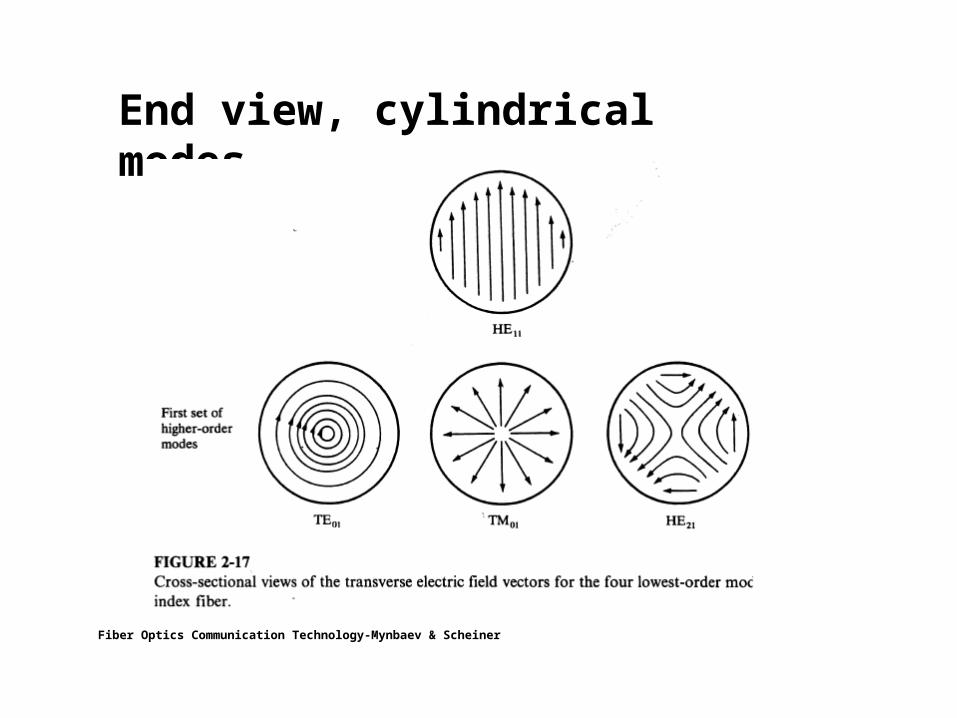
End view, cylindrical modes
Fiber Optics Communication Technology-Mynbaev & Scheiner

Cylindrical mode characteristics
Each mode has a specific
– Propagation constant β (=z)– Spatial field distribution– Polarization
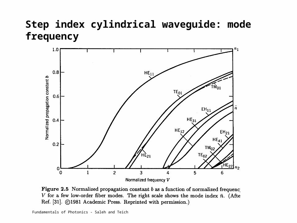
Step index cylindrical waveguide: mode frequency
Fundamentals of Photonics - Saleh and Teich

Oblique view, cylindrical modes
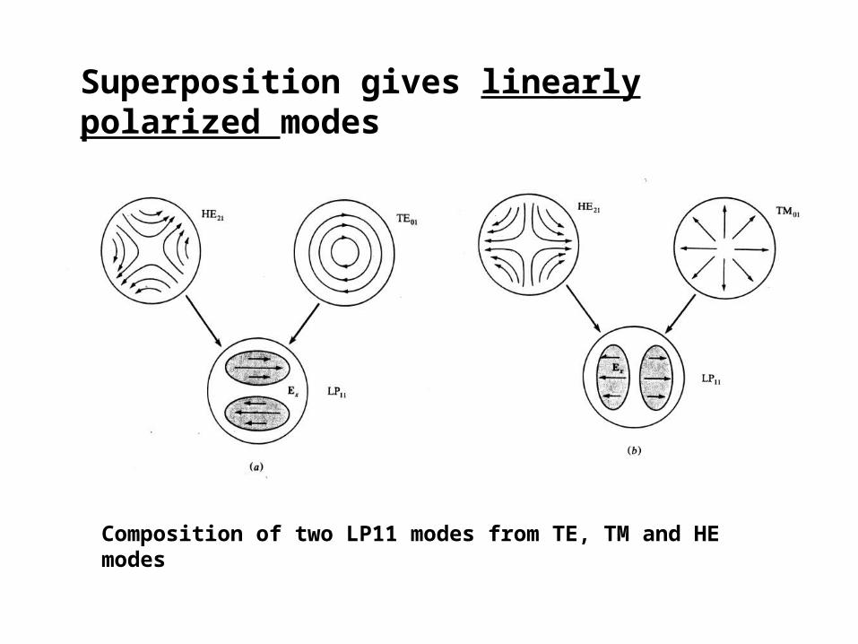
Superposition gives linearly polarized modes
Composition of two LP11 modes from TE, TM and HE modes
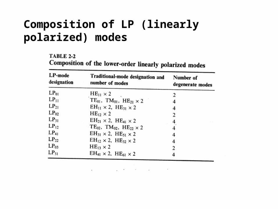
Composition of LP (linearly polarized) modes

Mode degeneracy = modes that can exist concurrently and independently
LP01 degeneracy:
LP11 degeneracy:
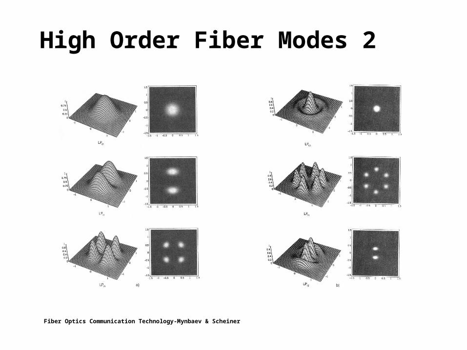
High Order Fiber Modes 2
Fiber Optics Communication Technology-Mynbaev & Scheiner

Below V=2.405, only one mode (= HE11) can be guided; the fiber is then single-mode.

Number of Modes
Graphical Constructionto estimate the total number of Modes
Propagation constant of the lowest mode vs. V number
2 20 1 2 1
0 0
a 2πV=k a(n -n )=2 an 2Δ
λ λNAp
æ ö÷ç ÷» ç ÷ç ÷çè ø
Fundamentals of Photonics - Saleh and Teich
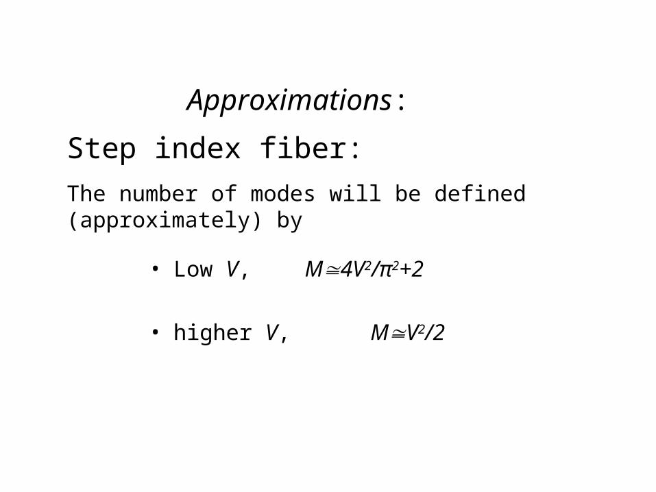
Approximations:
• Low V, M4V2/π2+2
• higher V, MV2/2
Step index fiber:
The number of modes will be defined (approximately) by

Behavior of modes vs normalized propagation constant /k and cutoff.

Cutoff conditions and evanescent content.
• For each mode, there is some value of the normalized frequency V below which the mode will not be contained (and guided) because the Bessel function (of the second kind) for the cladding does not go to zero with increasing r. The evanescent content of the mode is increased as the boundary condition is approached.
• Below V = 2.405, only one mode (= HE11) can exist in the fiber.
It is then called a single-mode fiber.
• Based on V, the number of modes can be reduced by decreasing the core radius and by decreasing the relative refractive index ∆ between core and cladding.

Single-mode fibers: V < 2.405
The only mode that can exist is the HE11 mode.
Birefringence if n1x and n1y are different.
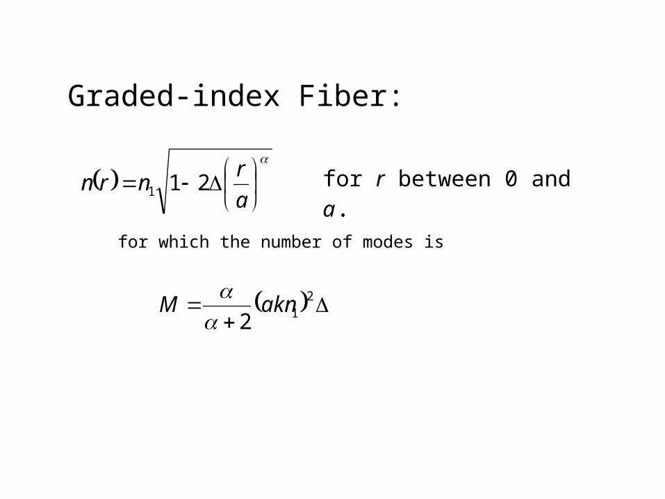
Graded-index Fiber:
for which the number of modes is
a
rnrn 211
212
aknM
for r between 0 and a.

Summary: comparison of the number of modes
2-D: Cylindrical Dielectric Guide
0
aV=2
λNAp
The V parameter characterizes the number of wavelengths that can fit across the core guiding region in a fiber.
For the metallic guide the number of modes is just the number of ½ wavelengths that can fit.
For dielectric guides it is the number that can fit but now limited by the angular cutoff characterized by the NA of the guide
1-D: reflecting metallic planes
1-D: Dielectric slab planes
2-D: Rectangular Metallic guide
2-D: Rectangular dielectric guide
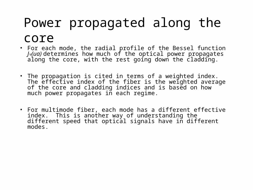
Power propagated along the core• For each mode, the radial profile of the Bessel function J(ua)
determines how much of the optical power propagates along the core, with the rest going down the cladding.
• The propagation is cited in terms of a weighted index. The effective index of the fiber is the weighted average of the core and cladding indices and is based on how much power propagates in each regime.
• For multimode fiber, each mode has a different effective index. This is another way of understanding the different speed that optical signals have in different modes.
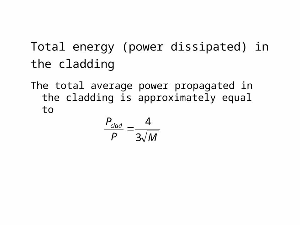
Total energy (power dissipated) in the cladding
The total average power propagated in the cladding is approximately equal to
MP
Pclad3
4

Power Confinement vs V-Number
This shows the fraction of the power that is propagating in the cladding vs the V number for different modes.
V for constant wavelength, and material indices of refraction is proportional to the core diameter a
As the core diameter is decreased, moreand more of each mode propagates in the cladding. Eventually it all propagates in the cladding and the mode is no longerguided
(Note misleading ordinate label)
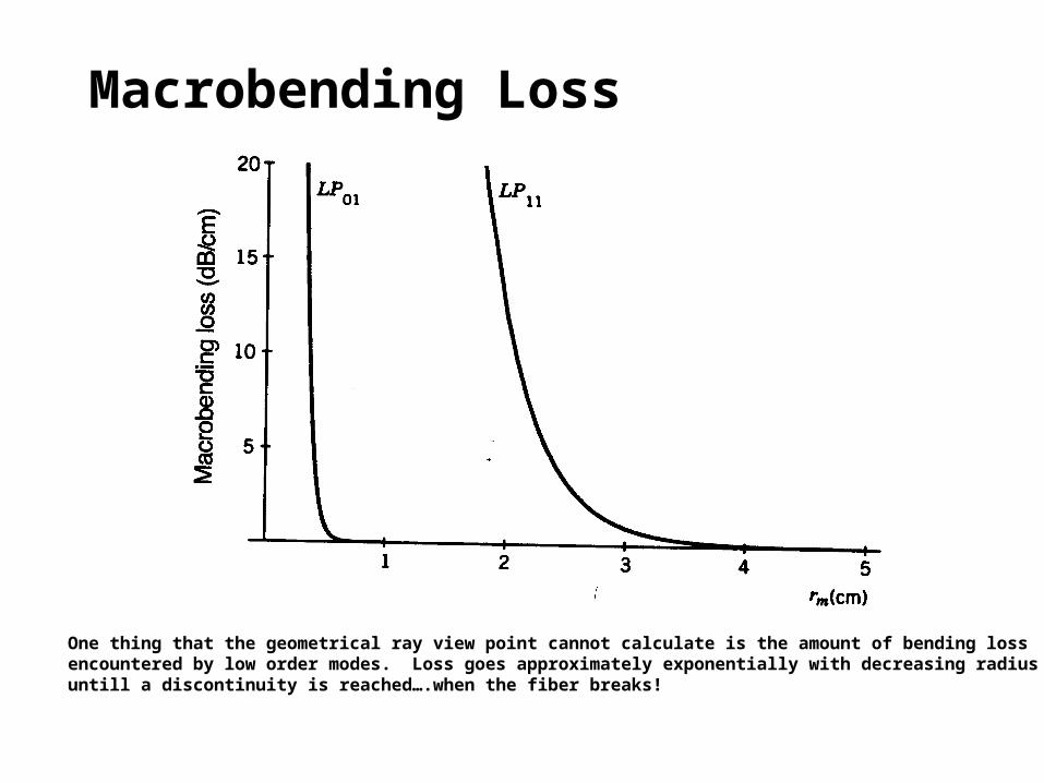
Macrobending Loss
One thing that the geometrical ray view point cannot calculate is the amount of bending lossencountered by low order modes. Loss goes approximately exponentially with decreasing radiusuntill a discontinuity is reached….when the fiber breaks!


![[Teich] amdis](https://static.fdocuments.net/doc/165x107/54581ee3af795998788b5361/teich-amdis.jpg)