ECE 477 Design Review Group 1 Spring 2005
52
ECE 477 Design Review ECE 477 Design Review Group 1 Group 1 Spring 2005 Spring 2005
description
ECE 477 Design Review Group 1 Spring 2005. Outline. Project overview Project-specific success criteria Block diagram Component selection rationale Packaging design Schematic and theory of operation Preliminary PCB layout Software design/development status Project completion timeline - PowerPoint PPT Presentation
Transcript of ECE 477 Design Review Group 1 Spring 2005

ECE 477 Design Review ECE 477 Design Review Group 1 Group 1 Spring 2005 Spring 2005

OutlineOutline• Project overview Project overview • Project-specific success criteriaProject-specific success criteria• Block diagramBlock diagram• Component selection rationaleComponent selection rationale• Packaging designPackaging design• Schematic and theory of operationSchematic and theory of operation• Preliminary PCB layoutPreliminary PCB layout• Software design/development statusSoftware design/development status• Project completion timelineProject completion timeline• Questions / discussionQuestions / discussion

Project OverviewProject Overview
• Receive input from three types of sensors: a Receive input from three types of sensors: a universal flame detector, directional universal flame detector, directional temperature sensors, and directional temperature sensors, and directional distance sensors distance sensors
• Inputs processed by microcontrollerInputs processed by microcontroller• Microcontroller drives maneuvering motors Microcontroller drives maneuvering motors
and servos to trigger the fire extinguisherand servos to trigger the fire extinguisher• Sounds a siren in the presence of a fireSounds a siren in the presence of a fire• Software to operate in three modes: off, “one Software to operate in three modes: off, “one
eye open” and patrol eye open” and patrol

Project-Specific Success CriteriaProject-Specific Success Criteria
• Ability for the software to maneuver the robot on an arbitrary indoor surface, avoiding walls or other objects while maneuvering.
• Ability to detect a nearby fire with minimal false positives (from non-flame heat sources) and determine the fire’s position relative to the robot.
• Ability to maneuver the robot into position to extinguish a fire based on data from the sensors.
• Ability to activate a fire extinguisher to extinguish a fire when the robot is already in the correct position.
• Ability to display state information to a user through an LCD interface

FIREBot Block DiagramFIREBot Block DiagramPower Supply
Universal Flame Detector
Wide Angle Flame Detectors
Narrow Angle Flame Detectors
Distance Sensors
Push Buttons
Siren
Sensor Platform
Servo
Microcontroller
Motor Drivers
LCD Output
Debug Port
Extinguisher Trigger
Servo

Component Selection RationaleComponent Selection RationaleMicrocontroller
The microcontroller must have sufficient peripherals to interface to all of the external components as well as sufficient FLASH and SRAM to store all the code and the data in operation. It must be inexpensive, easily available, and easy to prototype
• The Atmel ATMega32 – 4 PWMs, 8 Analog-To-Digital Converters, one UART– 32k FLASH, 2K SRAM, 1K EEPROM– Easily available in a PDIP Package
• The Motorola MC9S08GT32CFB– 4 PWMs, 8 Analog-To-Digital Converters, one UART, one IR UART– 32K FLASH and 2K SRAM. – Also available in a DIP package.
• We have tentatively chosen the Atmel ATMega32 because of low cost and good development package. The Motorola MC9S08GT32CFB-ND is a workable alternative.

Component Selection RationaleComponent Selection RationaleWide Angle Flame Detector
Wide Angle Flame Detectors find flames at a long distance and at a (relatively) wide-angle, and provide angular position location to the flame
• Hamamatsu UVTron – UV Detector which is very sensitive but with strong discrimination. Detects a candle at 5m.– Unacceptable: Updates every 3s
• UV Photodiode: Less sensative and less discrimination, but analog– Very low output current– Unacceptable: Didn’t detect flames in experiments, but reacted to
flourescent lights
• IR Photodiode: Much less discrimination, also analog– Reacts some to flourescent lights, but more to flames
• IR photodiode chosen to be better option since no way to get around problem of a UV photodiode under florescent lighting

Packaging DesignPackaging Design
• Packaging carefully designed to protect delicate parts without sacrificing operation
• Due to large amounts of heat, need a heat shield to protect the micro and some sensors
• Structure intended to be simple, easily accessible and easily modified
• Electronic components need to be protected from the chemical released by fire extinguisher to put out fire
• Robot powered by an onboard rechargeable battery• Onboard 4 lb fire extinguisher used to extinguish fires

Schematic/Theory of OperationSchematic/Theory of OperationThe FIREbot Electrical Schematics are built in a hierarchical structure, with
blocks performing the following functions:
• Power Supply• Universal Flame Detector• Wide Angle Flame Detector• Narrow Angle Flame Detector• Distance Sensors• Push Buttons• Microcontroller• Motor Drivers• Sensor Platform Driver• Extinguisher Trigger• Siren• LCD Outputs• Debug Port

Power Supply UnitPower Supply Unit
• The power supply block outputs 4 voltage rails• A 5V rail for digital components (Switching
Regulator)• A 5V rail for analog sensors (Linear Regulator)• A 5V rail for servos (Switching Regulator)• A 12V rail for analog components• Three separate 5V rails isolate the noise caused
by each type of component• p-channel power MOSFETs used so
microcontroller can turn off all but Digital rail
Sheet 15

Power Supply Unit Top LevelPower Supply Unit Top Level

Switching Power SupplySwitching Power Supply
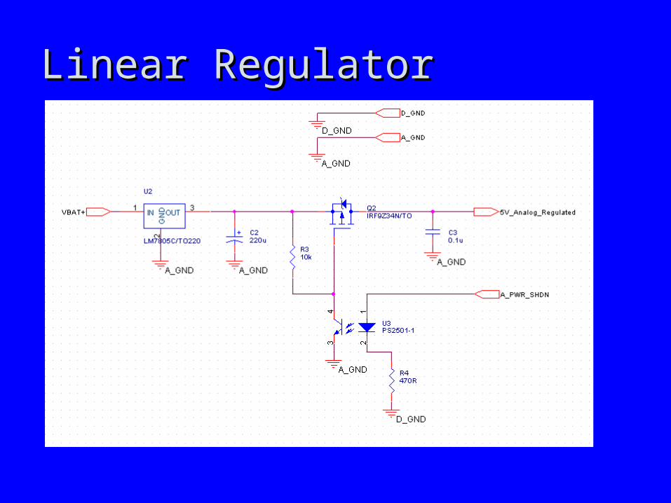
Linear RegulatorLinear Regulator
Universal Flame DetectorUniversal Flame Detector
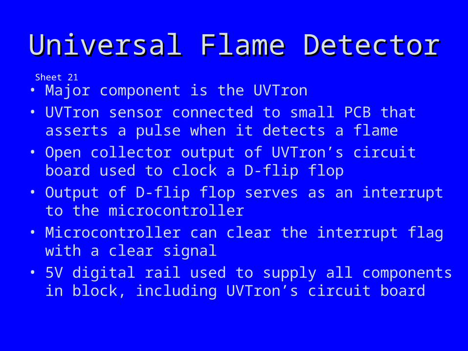
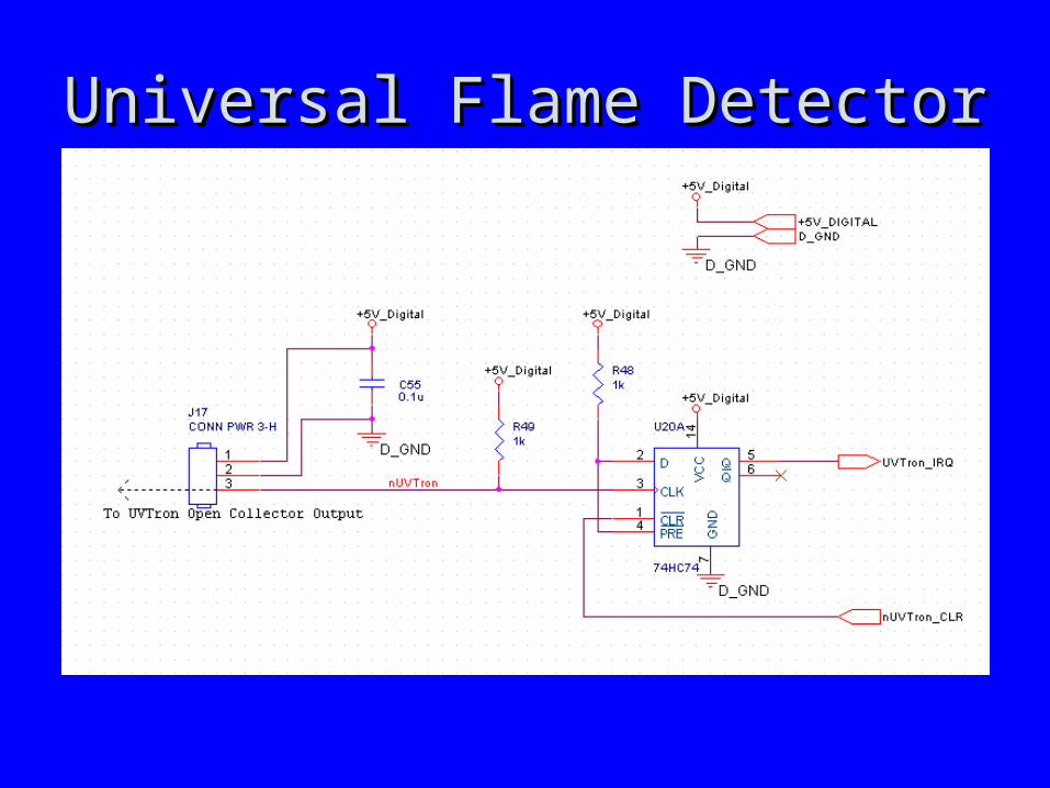
• Major component is the UVTron• UVTron sensor connected to small PCB that asserts a
pulse when it detects a flame• Open collector output of UVTron’s circuit board used to
clock a D-flip flop• Output of D-flip flop serves as an interrupt to the
microcontroller• Microcontroller can clear the interrupt flag with a clear
signal• 5V digital rail used to supply all components in block,
including UVTron’s circuit board
Sheet 21
Universal Flame DetectorUniversal Flame Detector
Wide Angle Flame DetectorWide Angle Flame Detector
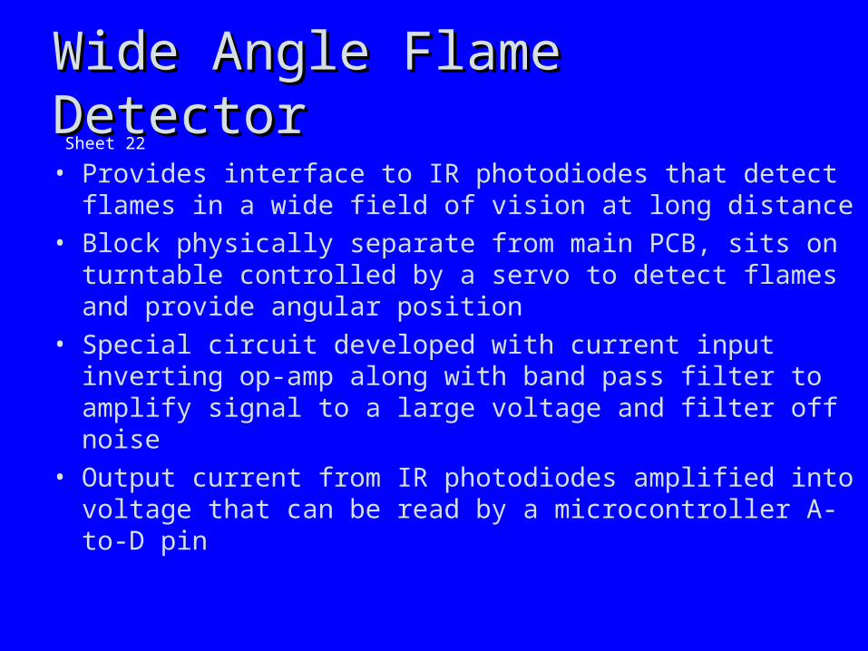
• Provides interface to IR photodiodes that detect flames in a wide field of vision at long distance
• Block physically separate from main PCB, sits on turntable controlled by a servo to detect flames and provide angular position
• Special circuit developed with current input inverting op-amp along with band pass filter to amplify signal to a large voltage and filter off noise
• Output current from IR photodiodes amplified into voltage that can be read by a microcontroller A-to-D pin
Sheet 22

Wide Angle Flame DetectorsWide Angle Flame Detectors
Narrow Angle Flame DetectorNarrow Angle Flame Detector
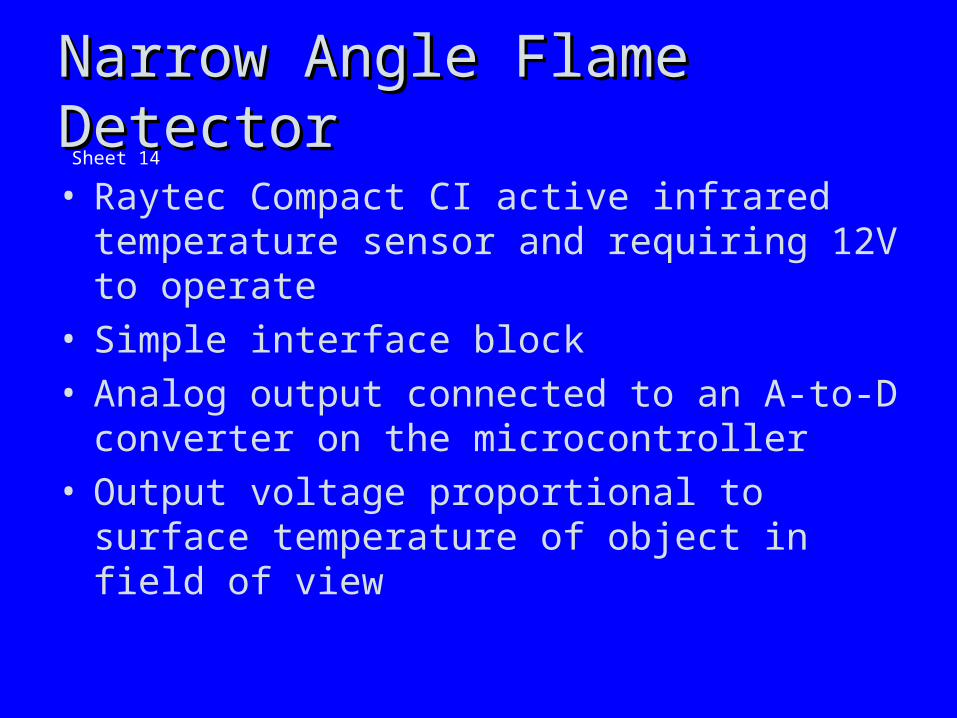
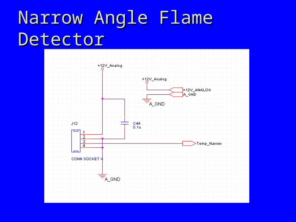
• Raytec Compact CI active infrared temperature sensor and requiring 12V to operate
• Simple interface block• Analog output connected to an A-to-D converter on
the microcontroller• Output voltage proportional to surface temperature
of object in field of view
Sheet 14
Narrow Angle Flame DetectorNarrow Angle Flame Detector
Proximity SensorsProximity Sensors
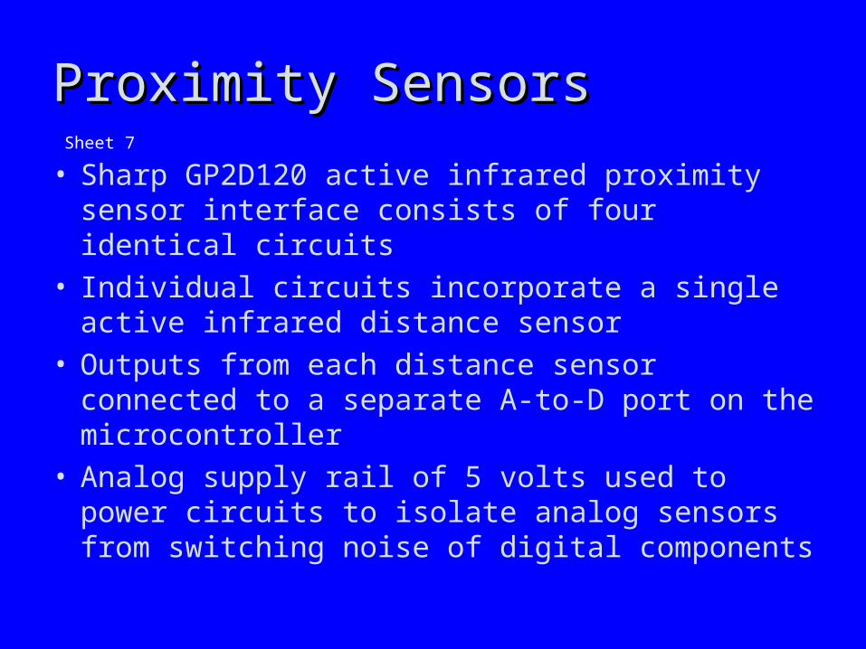
• Sharp GP2D120 active infrared proximity sensor interface consists of four identical circuits
• Individual circuits incorporate a single active infrared distance sensor
• Outputs from each distance sensor connected to a separate A-to-D port on the microcontroller
• Analog supply rail of 5 volts used to power circuits to isolate analog sensors from switching noise of digital components
Sheet 7

Proximity SensorsProximity Sensors
MicrocontrollerMicrocontroller
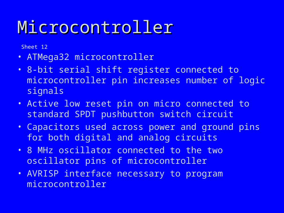
• ATMega32 microcontroller• 8-bit serial shift register connected to microcontroller pin
increases number of logic signals• Active low reset pin on micro connected to standard
SPDT pushbutton switch circuit• Capacitors used across power and ground pins for both
digital and analog circuits• 8 MHz oscillator connected to the two oscillator pins of
microcontroller• AVRISP interface necessary to program microcontroller
Sheet 12

MicrocontrollerMicrocontroller

Servo Motor DriversServo Motor Drivers
• Extinguisher Trigger and Sensor Platform Drive blocks identical, controlling similar servos
• Optical isolation for PWM signals• Decoupling capacitors for power• Dedicated 5V rail for servos to prevent noise on
other power lines
Sheets 8 and 19
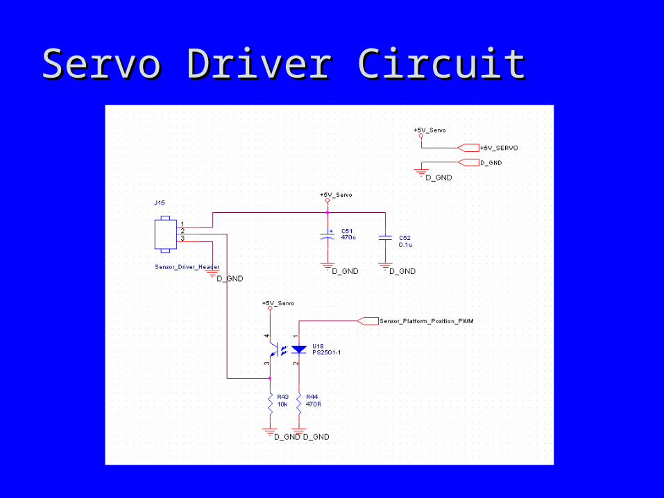
Servo Driver CircuitServo Driver Circuit

DC Motor DriversDC Motor Drivers
• Block responds to signals from microcontroller to drive the two power motors of FIREBot
• PWM used to control speed of each motor• Inputs are 8 digital signals from micro 4 for each
motor• Signals are Forward, Reverse, Brake, and PWM• Outputs are analog drive voltages connecting
directly to positive and negative terminals of the power motors
• 3 parts: glue logic, H-bridges, snubbers
Sheets 13 and 10
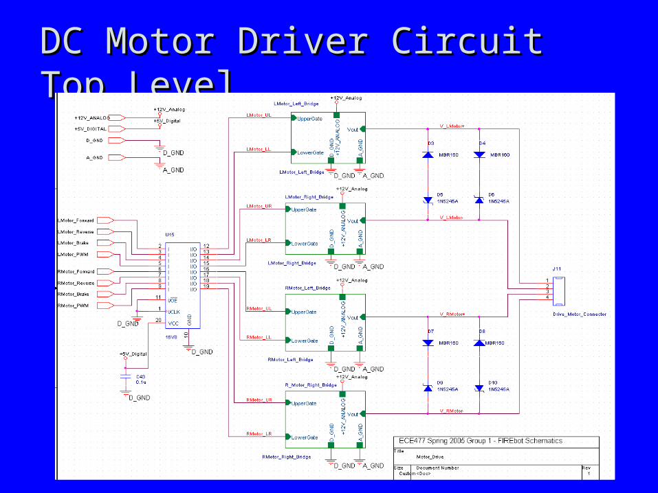
DC Motor Driver Circuit Top LevelDC Motor Driver Circuit Top Level
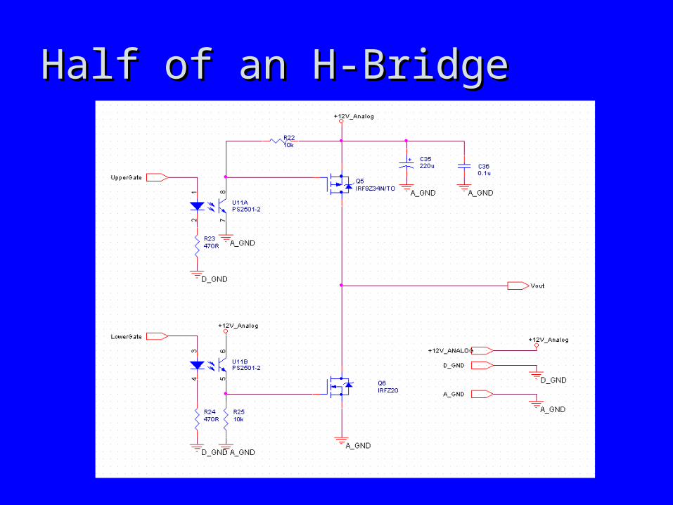
Half of an H-BridgeHalf of an H-Bridge

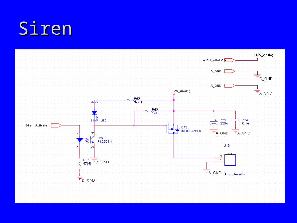
Siren InterfaceSiren Interface
• Interfaces a 12V siren to a pin of the micro• Input is Siren_Activate signal from the micro• Output is positive and negative terminals of siren• Optically isolated Siren_Activate signal controls
gate of FET to switch positive terminal of siren.• Activated LED is alternative to siren if necessary
Sheet 20
SirenSiren

Serial Debug Port InterfaceSerial Debug Port Interface
• Provides an RS-232 interface through which external PC can connect to FIREBot
• Can also be used to send simple commands• TX and RX are 5V digital signals connected
directly to micro• TX and RX signals optically isolated from analog
circuitry• TX and RX signals level-shifted to +/-12V logic
levels on RS-232• Outputs to pins of DB9 serial connector
Sheet 6

Serial Debug InterfaceSerial Debug Interface
Push ButtonsPush Buttons
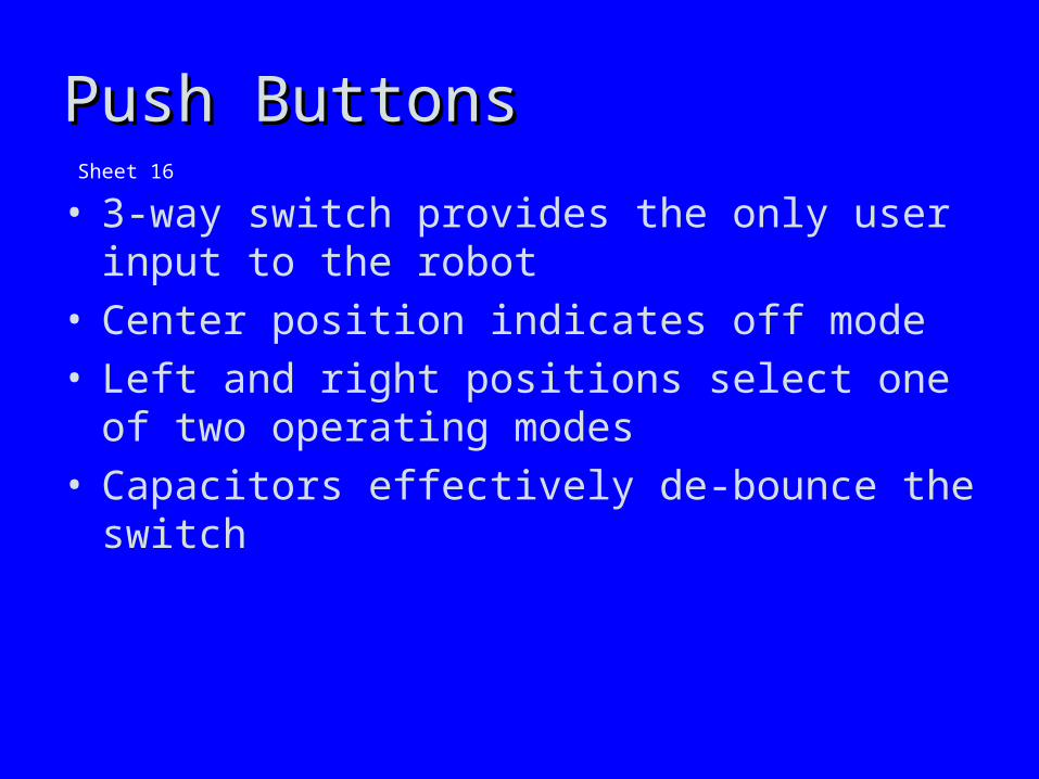
• 3-way switch provides the only user input to the robot
• Center position indicates off mode• Left and right positions select one of two
operating modes• Capacitors effectively de-bounce the switch
Sheet 16

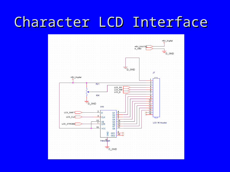
Character LCD InterfaceCharacter LCD Interface
• 20x4 Character LCD for status feedback20x4 Character LCD for status feedback• LCD interface based on 74HC74 8-bit serial shift
register• Shift register input driven by port pin on micro• Shift register reduces number of port pins
required send data LCD from eight to one• Other LCD control signals (i.e. LCD_STROBE)
driven directly by port pins on micro• Potentiometer to control contrast of LCD
Sheet 9
Character LCD InterfaceCharacter LCD Interface

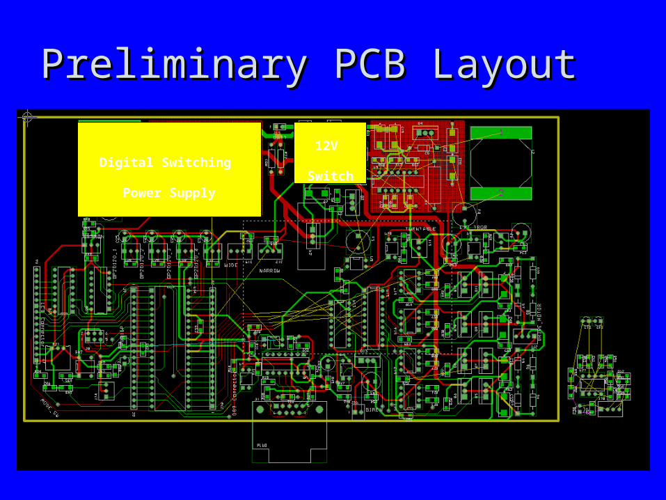
Preliminary PCB LayoutPreliminary PCB Layout

Preliminary PCB LayoutPreliminary PCB Layout
Digital Switching
Power Supply
Preliminary PCB LayoutPreliminary PCB Layout
Digital Switching
Power Supply
12V
Switch
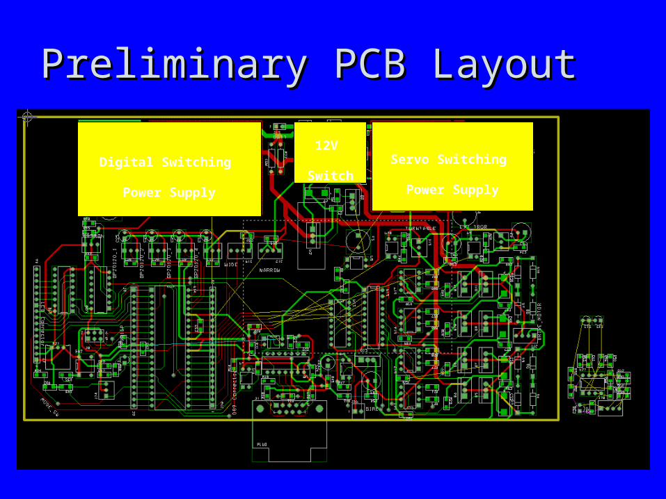
Preliminary PCB LayoutPreliminary PCB Layout
Digital Switching
Power Supply
Servo Switching
Power Supply
12V
Switch

Preliminary PCB LayoutPreliminary PCB Layout
Digital Switching
Power Supply
Servo Switching
Power Supply
Analog Flame &
Proximity Sensors`
12V
Switch

Preliminary PCB LayoutPreliminary PCB Layout
Digital Switching
Power Supply
Servo Switching
Power Supply
Analog Flame &
Proximity Sensors`
12V
Switch
5V Linear
Regulator

Preliminary PCB LayoutPreliminary PCB Layout
Digital Switching
Power Supply
Servo Switching
Power Supply
Analog Flame &
Proximity Sensors`
Servo Motor Drivers
12V
Switch
5V Linear
Regulator

Preliminary PCB LayoutPreliminary PCB Layout
Digital Switching
Power Supply
Servo Switching
Power Supply
Analog Flame &
Proximity Sensors`
Servo Motor Drivers
12V
Switch
5V Linear
Regulator
LCD
Display

Preliminary PCB LayoutPreliminary PCB Layout
ATMega32
Digital Switching
Power Supply
Servo Switching
Power Supply
Analog Flame &
Proximity Sensors`
Servo Motor Drivers
12V
Switch
5V Linear
Regulator
LCD
Display

Preliminary PCB LayoutPreliminary PCB Layout
ATMega32
Digital Switching
Power Supply
Servo Switching
Power Supply
Serial Debug
Port
Analog Flame &
Proximity Sensors`
Servo Motor Drivers
12V
Switch
5V Linear
Regulator
LCD
Display
Preliminary PCB LayoutPreliminary PCB Layout
ATMega32
Digital Switching
Power Supply
Servo Switching
Power Supply
Serial Debug
Port Siren
Analog Flame &
Proximity Sensors`
Servo Motor Drivers
12V
Switch
5V Linear
Regulator
LCD
Display

Preliminary PCB LayoutPreliminary PCB Layout
ATMega32
Digital Switching
Power Supply
Servo Switching
Power Supply
Serial Debug
Port Siren
Analog Flame &
Proximity Sensors`
Servo Motor Drivers
12V
Switch
5V Linear
Regulator
DC Motor
H-Bridges
LCD
Display

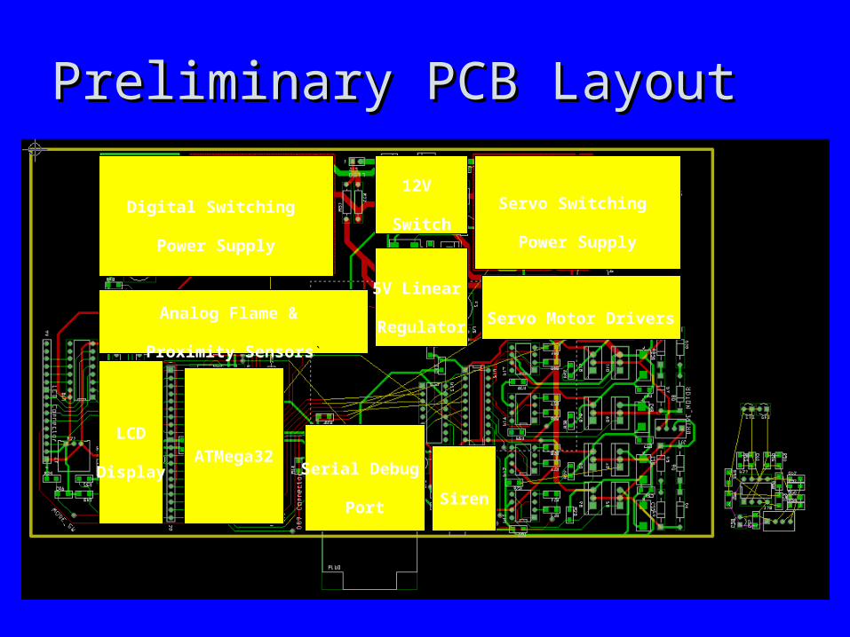
Preliminary PCB LayoutPreliminary PCB Layout
ATMega32
Digital Switching
Power Supply
Servo Switching
Power Supply
Serial Debug
Port Siren
Analog Flame &
Proximity Sensors`
Servo Motor Drivers
12V
Switch
5V Linear
Regulator
DC Motor
H-Bridges
LCD
Display
Turntable
Mounted
PCB

Software Design/Development StatusSoftware Design/Development Status
Control State Machine
Patrol Mode Functions
Approach Mode Functions
One-Eye-Open Mode Functions
Extinguish ModeFunctions
Drive Module Obstacle Module Scanner Module
Wide Angle Flame Detector
Module
Narrow Angle Flame Detector
Module
Universal Flame Detector Module
Extinguish Module
Drive MotorsIR Range Sensors
Scanner PlatformServo
IR Photodiode Circuits
Scanner Temperature Sensor
Extinguish ServoUVTron Board
ECE477 Group 1Spring 2005Software Block Diagram
Software
Hardware

Patrol Mode
Approach Fire Mode
One Eye Open
Mode
Extinguish Fire Mode
OFF Mode Detect Fire
No Fire
Detect Fire
No Fire
OEO Mode Button Pressed
Patrol Mode Button Pressed
OFF Mode Button Pressed
OFF Mode Button Pressed
OFF Mode Button Pressed
OFF Mode Button Pressed
OEO Mode Button Pressed
OEO Mode Button Pressed
Patrol Mode Button Pressed Patrol Mode
Button Pressed
OFF Mode Button Pressed
ECE477 Group 1 Spring 2005 Software State Diagram
Software Design/Development StatusSoftware Design/Development Status

Project Completion TimelineProject Completion Timeline• Week of March 7Week of March 7
– Complete PCB layout Complete PCB layout – Learn AVR development environment.Learn AVR development environment.
• Week of March 21Week of March 21– Populate PCBPopulate PCB– Install all sensors and parts on structureInstall all sensors and parts on structure– Begin writing hardware control state machinesBegin writing hardware control state machines
• Week of March 28Week of March 28– Complete Writing and Verify hardware control state machinesComplete Writing and Verify hardware control state machines
• Week of April 4Week of April 4– Write and verify One-Eye-Open and Extinguish software State MachinesWrite and verify One-Eye-Open and Extinguish software State Machines
• Week of April 11Week of April 11– Write and verify Patrol Mode software state machineWrite and verify Patrol Mode software state machine
• Week of April 18Week of April 18– Write and verify Approach Mode software state machineWrite and verify Approach Mode software state machine
• Week of April 25Week of April 25– Verify system functionalityVerify system functionality
• Week of May 2Week of May 2– Demonstrate system functionalityDemonstrate system functionality– Write Final documentationWrite Final documentation

Questions / DiscussionQuestions / Discussion