
ECE 4411 Voltage Regulation. ECE 4412 Voltage Regulation (continued) E nl = no-load output voltage...
17
ECE 441 1 Voltage Regulation % 100% nl rated rated E V reg per unit regulation V regulation per unit
-
date post
20-Dec-2015 -
Category
Documents
-
view
222 -
download
0
Transcript of ECE 4411 Voltage Regulation. ECE 4412 Voltage Regulation (continued) E nl = no-load output voltage...

ECE 441 1
Voltage Regulation
% 100%
nl rated
rated
E Vreg per unit regulation
V
regulation per unit

ECE 441 2
Voltage Regulation (continued)
• Enl = no-load output voltage– Measure with a voltmeter when no load is
connected to the transformer
• Vrated = voltmeter reading at the output terminals when the transformer
is supplying the rated apparent power
• These voltages are all either High-side or Low-side voltages!
ECE 441 3
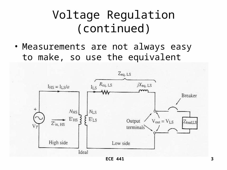
Voltage Regulation (continued)
• Measurements are not always easy to make, so use the equivalent circuit.

ECE 441 4
When the breaker is open, no current flows in Req,LS , jXeq,LS , or ZLOAD,LS , therefore
Vout = VLS = E’LS = Enl

ECE 441 5
With rated load on the secondary, E’LS = ILSZeq,LS + VLS
ILS = rated low-side current at a specified power factor
VLS = rated low-side voltage
Zeq,LS = equivalent impedance of the transformer referred to the low-side
E’LS = no-load low-side voltage

ECE 441 6
Example 2.7
• The equivalent low-side parameters of a 250kVA, 4160 – 480V, 60 Hz transformer areReq,LS = 0.00920 Ω and Xeq,LS = 0.0433 Ω. The transformer is operated in the step-down mode and is delivering rated current at rated voltage to a 0.840 power-factor lagging load.
• Determine

ECE 441 7
– the no-load voltage – The actual input voltage on the high-side– The high-side current– The input impedance– The voltage regulation– The voltage regulation if the power factor of
the load is 0.840 leading– Sketch the tip-to-tail phasor diagram of the
secondary circuit for the 0.840 power factor lagging load. Show all voltage drops.

ECE 441 8
1
250,000520.83
480
cos (0.840) 32.86 32.86 ( )
480 0
520.83 32.86
LS
LS
LS
kVAI A
V
lagging
V V
I A

ECE 441 9
Low-Side Output

ECE 441 10
', ,
'
'
'
'
520.83 32.86 (0.0092) 520.83 32.86 ( 0.0433) 480 0
4.79 32.86 22.55 57.14 480 0
4.024 2.599 12.235 18.94 480 0
496.53 1.886
LS LS eq LS LS eq LS LS
LS
LS
LS
LS
E I R I jX V
E j
E
E j j j
E V

ECE 441 11
'
'
' '
41608.667
480
8.667(496.53 1.886 )
4303.4 1.886
HS HS
LS LS
T HS LS
T
E Va
E V
V E aE
V V
ECE 441 12
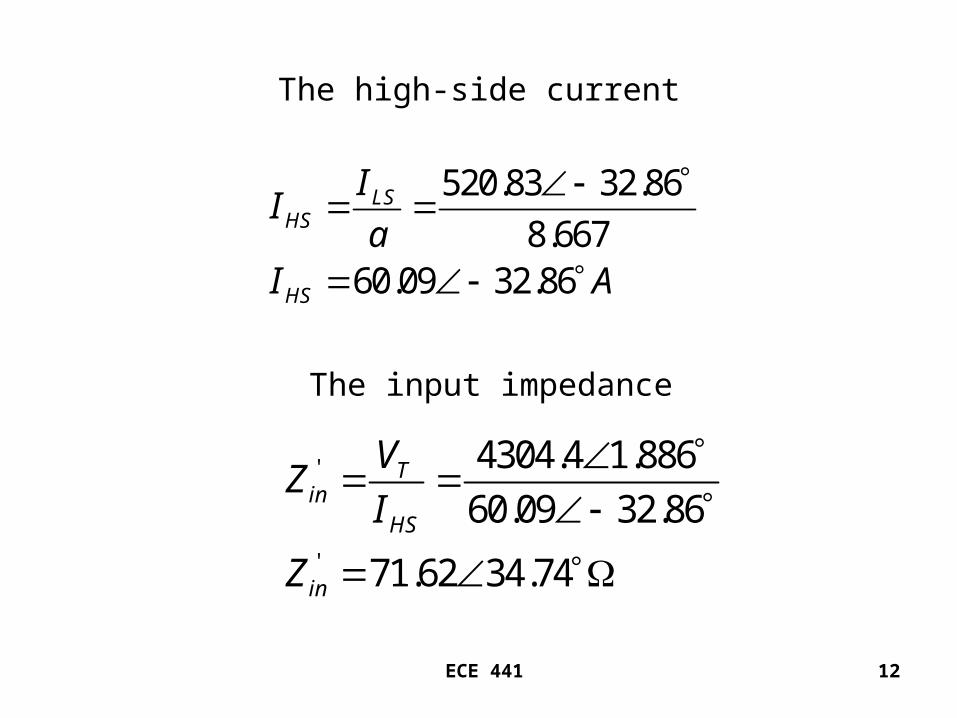
The high-side current
520.83 32.86
8.66760.09 32.86
LSHS
HS
II
aI A
The input impedance
'
'
4304.4 1.886
60.09 32.86
71.62 34.74
Tin
HS
in
VZ
I
Z

ECE 441 13
The voltage regulation
496.53 4800.0344 3.44%
480nl rated
rated
E Vreg
V
ECE 441 14
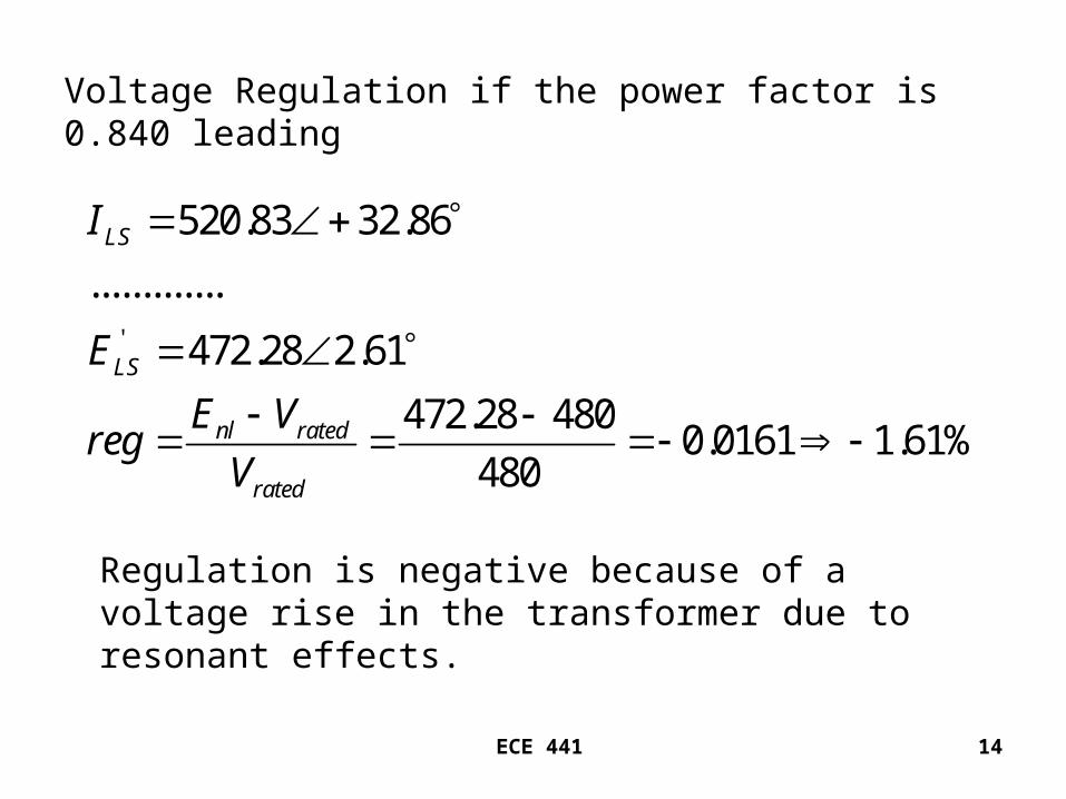
Voltage Regulation if the power factor is 0.840 leading
'
520.83 32.86
.............
472.28 2.61
472.28 4800.0161 1.61%
480
LS
LS
nl rated
rated
I
E
E Vreg
V
Regulation is negative because of a voltage rise in the transformer due to resonant effects.

ECE 441 15
The “tip-to-tail” phasor diagram for the 0.840 power factor lagging load.
,
,
520.83 32.86 (0.0092) 4.79 32.86
520.83 32.86 ( 0.0433) 22.6 57.14
LS eq LS
LS eq LS
I R V
I X j V

ECE 441 16
Component Phasors

ECE 441 17
Tip-to-Tail Addition


