
EC Systems Status & Prospects - Nucleus Meeting Proceedings/4th DEMO... · “pen point” a spot...
54
EC Systems Status & Prospects 4th IAEA DEMO Programme Workshop 15–18 November 2016 Karlsruhe, Germany Presented by G.G. Denisov Institute of Applied Physics, Nizhny Novgorod, 603950, Russia Gycom Ltd, Nizhny Novgorod, 603155 Russia
-
Upload
nguyendien -
Category
Documents
-
view
214 -
download
0
Transcript of EC Systems Status & Prospects - Nucleus Meeting Proceedings/4th DEMO... · “pen point” a spot...

EC Systems Status & Prospects
4th IAEA DEMO
Programme Workshop
15–18 November 2016
Karlsruhe, Germany
Presented by G.G. Denisov
Institute of Applied Physics, Nizhny Novgorod, 603950, Russia
Gycom Ltd, Nizhny Novgorod, 603155 Russia

2
• M.Henderson. ITER IO
• EU team (S. Garavaglia, W. Bin, A. Bruschi, G. Granucci,
G.Grossetti, J.Jelonnek, A. Moro N. Rispoli D. Strauss,
M.Thumm, Q.M. Tran and T. Franke, …)
• R. Ikeda. QST, Naka, Japan
• T. Kariya. University of Tsukuba, Japan
Russian colleagues from
• Institute of Applied Physics
• Gycom Ltd,
• Kurchatov Institute
• ITER DA
• RT Soft
Contributions:

3
OUTLINE
• First steps and main events
• List of running and near future EC systems
• EC systems: aims and content
• ITER EC system
• Necessary steps from ITER to DEMO
• New developments for future EC systems
o Higher gyrotron frequency
o Multi-frequency operation
o Broad band window
o Remote steering launcher
Summary

4
• First steps and main events
• List of running and near future EC
systems
• EC systems: aims and content
• ITER EC system
• Necessary steps from ITER to DEMO
• New developments for future EC
systems
o Higher gyrotron frequency
o Multi-frequency operation
o Broad band window
o Remote steering launcher

Some dates from “ancient” history
1964 – first experiments with gyrotrons
70s – 100 GHz/1MW/ 100 mks/ TE22.2
28 GHz/100kW/CW
first use to heat plasma at TM-3, TUMAN-2
80s – 100GHz/2.1MW/10mks/coax./
0.5 MW/sec
wide use in plasma experiments

Main Events
1990-2006
First depressed collectors in megawatt gyrotrons
First CVD diamond gyrotron windows
Demonstration of CW operation of MW power gyrotrons
Remote steering antenna concept
MW gyrotron complexes at major fusion installations
Last decade 2007-2016
Great progress in ITER system development
• Demonstrated required gyrotron parameters/Reliability tests
• Manufacturing began
Results on 1.5-2 MW gyrotron models
Multi-frequency gyrotrons
Higher frequency gyrotrons (first steps)
New ideas

ECW systems (examples)
Future installations:
ITER 24 1MW/170GHz/3600 sec 2025
JT-60SA 7 110/138 GHz/100 sec 2019
DEMO 50 MW/ 230 GHz/ CW
Running installations with ECW systems:
DIII-D, FTU, TCV, JT-60U, LHD, ASDEX-Upgrade, T-10, W7-AS, …
80-170 GHz/ 2-5 MW/1-10 sec
Developments for running machines:
EAST 140 GHz/ 5 MW/ 1000 sec
KSTAR 105/140 GHz/ * MW/ 300 sec
W7-X 10 1MW/140GHz/ 1800 sec
JET just discussions since 2000

8
• First steps and main events
• List of running and near future EC systems
• EC systems: aims and content
• ITER EC system
• Necessary steps from ITER to DEMO
• New developments for future EC systems o Higher gyrotron frequency
o Multi-frequency operation
o Broad band window
o Remote steering launcher

How ECH works
9
Beam steering from external system
(mirrors in upper port)
mm-wave beams launched from
either the upper or equatorial ports
Power absorbed locally,
where B satisfies:
Microwaves give energy to electrons when
electron cyclotron resonance occurs

10
Heating and Current drive source
that is both localized and steerable
Barrier(window) is possible
Localized: 4cm to 20cm deposition width
Useful for:
ECH is a surgical tool that can
“pen point” a spot in the plasma cross section
to heat plasma and/or drive current
Current Profile Tailoring
deposit ˜0.8MA from center to mid radius
edge center
EL
MHD Control
deposit ˜0.2MA inside rotating 4cm island
UL

EC system includes
Main components
• Gyrotrons (many)
• Transmission lines (many) HE11 waveguide or mirrors
• Barrier windows (many)
• Launchers (several)
Aix components
• HV and LV power supplies
• Control system
• Cooling system
• Safety

Ramp-down Helps to ramp-down plasma softly
Tailors current profile to avoid instabilities
EC is used through out the Plasma Discharge
12
EC Power
Plasma Current
Start-up “Provides “spark” to initiate plasma
Ramp-up Good absorption when plasma is not “hot”
Helps to build up temperature and current
Tailors current profile for stabilising plasma
Helps to achieve High confinement mode
Burn Tailors Current profile
Controls sawtooth and NTMs
maintains “hot” plasma
Ramp
down Startup Ramp
up Burn

Based on existing practices (AUG, DIII-D, JT-60U, TCV, etc)
TID: Targeted and Impacts Design // TND Targeted and Not impacting Design
EC “App” Matrix
ITER EC Targeted Physics Functions
13

14
• First steps and main events
• EC systems: aims and content
• List of running and near future EC systems
• ITER EC system
• Necessary steps from ITER to DEMO
• New developments for future EC systems o Higher gyrotron frequency
o Multi-frequency operation
o Broad band window
o Remote steering launcher

ITER Electron Cyclotron System
15
Method Advantage Disadvantage
EC Couples high power
microwaves to e
Extremely localized heating
and current deposition
Uses external actuators to
change deposition location
Effectively 100% coupling
- Indirect heating of ions
- Limited long pulse high
power experience
Power Supplies (50MW)
24 sources (24MW)
24 Transmission
lines
5 Launchers (20MW)

NTM control
16
Upper Launcher optics designed for:
Deposition 4 to 8cm
Power can modulate up to 5kHz
24 beams overlap in plasma (very narrow profiles)
Upper Launcher is like a ‘predator drone’:
it watches plasma from above and hits each island as they rotate in sight
Last mirror steers deposition over 50% of plasma

Equatorial Launcher
17
Primary Role
Note that beams now steer in poloidal direction

Nuclear
Occupational
Safety
EC Functional Requirements
18
Compliance with Load Specifications
Nuclear
Seismic
Plasma
Vacuum
Over pressure events
Seismic
Environmental
Fire
Combined loads
Integration
RAMI (reliability, availability, maintainability, inspectability)
EC HCD Applications (Baseline and Power Upgrades)
First Plasma Operations (inject 6.7MW)
Second Plasma Operations (inject 20MW)
Upgrade Operations (inject additional ≤20MW)

EU IN JA RF US
PS 8 sets 4 main 8 APS/BPS
RF Source 6MW 2MW 8MW 8MW
TL 24
Launchers 4 (UL) 1 (EL)
DAs have chosen the EC System Procurements Divisions
19
5 Parties provide in-kind procurement
of the 4 EC subsystems

Requirement: >39%
Achieving: between 39 and 44%
(does not include services)
Electrical Efficient from Grid to Plasma
Plug to Plasma Efficiency
20

Actuators: Launchers
21
Upper launcher 4 ports, 8 entries each
Control of MHD activity (NTMs)
Equatorial launcher: 1 Port, 24 entries
Central heating and current drive
20MW
Switch
(≤3 sec)

EC Transmission Line
22
Microwave Sources
Tokamak
Transmission Line Path
Length ˜160m
Power Handling 1.4MW
Pulse length 3’600s (25% duty cycle)
Power Transmission Efficiency ≥90%
Mode conversion efficiency ≥95%
Transmission Line Overview:

Universal Polarizer (>99% O or X mode coupling)
Actuators: Transmission Line
23
24 switches directing power to either EL or UL
8 switches directing power to UL “upper” or “lower” Steering mirrors
Switching speed ≤3 sec
Polarization change ≤2 sec

EC system has to comply with Tritium Confinement
Safety
24
Diamond window
All-metal valve
Shutter Valve

Cathode (~-60kV)
@~1’000 C
Body (~+30kV)
Collector (ground)
electron beam
SC magnet
RF power
(~1MW)
Resonator
mm-waves
mode convertor
JA RF EU IN
TBD
1MW
1000s
50-55%
1MW
1000s
53%
0.8MW
100s
pulse length of 3’600sec
1MW at window with ≥95% TEM00 mode purity
LHe free cryomagnets
>50% efficiency (Pout/Pin)
170GHz Gyrotrons are rated for:
RF Sources (Gyrotrons)
25
Challenges:
Mass production
High Reliability
Higher Power (≥1.0MW)
Long life (≥5 years)
High mode purity (≥98%)
Partial Power modulation
5kHz
0.1mT < |Br| < 0.25mT (or
less)

HVPS: Main and Body for EU and RF gyrotrons
26
Main High Voltage Power Supply
(PSM based)
Parameter Value
Voltage ∼55kV
Current ∼110A
Pulse Length 3’600 sec
Duty cycle 25%
Body Power Supply
(PSM based)
Parameter Value
Voltage ∼35kV
Current <100mA
Pulse Length 3’600 sec
Duty cycle 25%
EU contract signed with
Ampegon
Current increased for
1.2 to 1.4 MW Gyrotrons

2025: first plasma (1 UL, 8MW EC for plasma initiation and maybe EL)
2028: second plasma and full 24MW EC system
<2035: D-T phase
General ITER EC Planning
Schedule: Objective at System Level
27
EC manufacturing, assembly and Operation Schedule
2018: Access to RF Building
2018-9: Start installation of PS, Gyrotrons, TL
2023-24: 1 UL plug and 8MW ready for operation
2024: All ex-vessel installed, ≥1 year commissioning for First Plasma
2027: All launchers installed
2028: Full system operating
2031: (Full NB and IC operating)

28
Current activities. Russian team. IAP/GYCOM
Gyrotrons/TL components for plasma fusion (2015-2016)
• ITER activity
• EAST (first ECW experiment) +1
• KSTAR (first delivery in 2015, acceptance test
completed) +1
• Asdex Upgrade
• TCV
• EU DA….
• New developments

ITER RF Source prototype
False floor
removed
Ion Pump Power Supply
Collector Sweep coil
Power Supply
Cathode Filament
Power Supply
Super Conductive
Magnet Power Supply
Gun Coil Power Supply
Collector DC coil Power
Supply
X and Y Correction coils Power
Supplies
Temperature Monitor

PROTOTYPE OF RF-DA RF POWER SOURCE, TEST REPORT
May 11 – 15, 2015, Nizhny Novgorod, Russia
Gyrotron together with
SCM, MOU and relief load
in the support structure
left picture
Waveguide with terminal
load and cooling manifolds
top right
Operator console with
control &protection cubicles
bottom right

Russian ITER RF Source pre-prototype
0
100
200
300
400
500
600
700
800
900
1000
1100
1 51 101 151 201 251
pulse sequencial number
pu
lse
du
rati
on
, s
regular cut-off internal arc
Gyrotron run test (2014) at 1MW output power
with pulse duration 500s and 1000s
Reliability > 95%
500s – 160 pulses
1000s – 55 pulses
New tube
conditioning

PROTOTYPE OF RF-DA RF POWER SOURCE TEST REPORT (Section 5)
May 11 – 15, 2015, Nizhny Novgorod, Russia
5. PRFS main output parameters
measurement and verification for
compliance for specified ones:
- operation frequency,
- power at the MOU output,
- generation efficiency
- НЕ11 mode content at MOU output
- pulse length
- duty factor
Required
170±0.25 GHz
≥0.96 MW
≥50%
≥95%
≥1000s
≤1/4
Measured
170.07 GHz
0.96 MW (±5%)
58%
97±1%
1000s
1/4
PRFS testing was carried out on Factory site following RF source prototype FAT Program
IDM_NCNC85 v.1.0 in presence of ITER organization (IO) representatives: C. Darbos, F. Gandini
and P. Vertongen.
FDR, October 2015; Manufacturing began in 2016

Two-frequency 140 / 105 GHz gyrotron with 1 MW output power and maximum pulse
duration 300 s. The parameters were successfully demonstrated at the customer site – NFRI /
Korea. At present time gyrotron operates at plasma machine KSTAR. Second two-frequency
gyrotron is planned for delivery to NFRI at the end of 2017.
140 GHz / 1 MW / 1000 s gyrotron operates at EAST machine / ASIPP / China since
mid of 2015 year. Second tube passed factory tests at July, 2016 and delivered to China.
The deliveries besides the gyrotrons include other components: cryomagnets
(JASTEC, Japan), matching optic units, elements of evacuated transmission lines and full
power evacuated dummy load.
Gyrotrons at factory and customer sites
Other gyrotrons for fusion installations (2/6)

34
• First steps and main events
• EC systems: aims and content
• List of running and near future EC systems
• ITER EC system
• Necessary steps from ITER to DEMO
• New developments for future EC systems o Higher gyrotron frequency
o Multi-frequency operation
o Broad band window
o Remote steering launcher

35
Necessary steps from ITER to DEMO
• Frequency increase 170 −−−> 230 GHz
• Module power increase 1.0 −−−> 1.5 MW
• Eff./reliability enhancement 50 −−−> 60 % / 95 --> 98%
• Multi-frequency operation avoid wide angle scanning
• Remote steering remove mirrors from magnetic field
and plasma
Mutual contradictions in goals
e.g.
- Higher frequency and higher power require bigger gyrotron cavity,
higher operating mode (affect gyrotron efficiency)
- More critical transmission line alignment (for higher f and P)

36
• First steps and main events
• List of running and near future EC systems
• EC systems: aims and content
• ITER EC system
• Necessary steps from ITER to DEMO
• New developments for future EC systems
o Higher gyrotron frequency
o Multi-frequency operation
o Broad band window
o Remote steering launcher

37
New developments, Russian team
• higher power and higher frequency gyrotrons
• phase locking of gyro-oscillator by external signal
Aim:
• Provide single mode gyrotron operation at very high-order modes
• Stabilize frequency while e-beam parameters are not stable
• Enhance efficiency
• Lock frequency and phase / Make several gyrotrons coherent

38

39

40

41

42

T. Kariya, T. Imai, R. Minami, T. Numakura, K. Tsumura, Y. Ebashi, Y. Endo, R. Ikezoe, Y. Nakashima : Plasma Research Center (PRC), University of Tsukuba
K. Sakamoto, Y. Oda, R. Ikeda, K. Takahashi, T. Kobayashi, S. Moriyama : National Institutes for Quantum and Radiological Science and Technology (QST)
T. Shimozuma, S. Kubo, Y. Yoshimura, H. Takahashi, H. Igami, S. Ito, K. Okada, S. Kobayashi, T. Mutoh : National Institute for Fusion Science (NIFS)
H. Idei, K. Hanada : Research Institute for Applied Mechanics, Kyushu University
K. Nagasaki : Institute of Advanced Energy, Kyoto University
M. Ono : Princeton University Plasma Physics Laboratory (PPPL)
T. Eguchi, Y. Mitunaka : Toshiba Electron Tubes and Devices Co., Ltd (TETD)
Univ. of Tsukuba is developing over 1 MW gyrotrons of
14GHz to sub-THz for Fusion Devices and for Demo-Reactor
in collaboration with
QST, NIFS, Kyushu Univ., Kyoto Univ., PPPL and TETD, based on 2 MW level result on the LHD 77 GHz gyrotron tube
FIP1-6Rcz
Development of Over MW Gyrotrons for Fusion at Frequencies from 14 GHz to Sub-terahertz
Presented by T. Kariya (Univ. Tsukuba)

Develop. of Sub-Terahertz (300 GHz) Gyrotron For ECH and ECCD at the DEMO reactor (Collabo. with QST)
Achieved 299.8 GHz, 522 kW, 2 ms with TE32,18 single-mode
Output Window Reflectance : 0% for TE32,18, 23% for TE30,19
With SiO2 disk 20% for TE32,18,2% for TE30,19
Window reflection affects the oscillation mode characteristics, which can be removed by installing a built-in mode converter. The aimed design single mode would be realized. M
ain
Co
il C
urr
en
t [A
]
Mai
n C
oil
Cu
rre
nt
[A] Gun Coil Current [A] Gun Coil Current [A]
Mode maps (cavity vs. gun coil current) 295.65 GHz, 542 kW (TE31,18) 301.8 GHz, 528 kW (TE30,19)

220 - 240 GHz Oscillation by 300 GHz GyrotronMagnetic Field
at Cavity [T]
Beam Radius
[mm]
Estimated
Oscillation Mode
Estimated
Frequency [GHz]
10.11 5.57 TE28,15(-) 253.99
9.80 5.58 TE27,15(-) 250.04
9.60 5.59 TE28,14(-) 243.9
9.54 5.59 TE25,15(+) 242.1
9.43 5.6 ? ?
9.07 5.61 TE24,14(+) 228.13
8.90 5.62 TE26,13(-) 225.96
It was found that designed ultra-high volume mode of sub-THz would be stably obtained with conventional cylindrical cavity. Step tunable single mode oscillations were also confirmed. These result contributes greatly to the step frequency tunable gyrotron in the sub-THz region for the DEMO-Reactor.
300kW
Stable single mode oscillation at each tuned freq. in 225–254 GHz band
Develop. of Sub-Terahertz (300 GHz) Gyrotron For ECH and ECCD at the DEMO reactor (Collabo. with QST)
short pulse, efficiency

Design study of 154/116 GHz Dual-frequency gyrotron -----
For ECH and EBW heating at LHD (Collab. With NIFS)
Three 77 GHz and two 154 GHz gyrotrons have contributed greatly to extending the LHD plasma performance with their total plasma injection power of 5.4 MW. • High Te plasma : Te = 20 keV • Steady-state plasma : line averaged ne = 1.1× 10¹⁹ m-3 Te = 2.5 keV was sustained for 2351 s.
Based on the above and the 2 MW level 77 GHz gyrotron development results, a new 154/116 GHz dual-frequency gyrotron is desired for expanding the LHD plasma parameters.
Best matching of cavity, Mode convertor and window was obtained with combination of Cavity oscillation modes
TE28,9 at 154 GHz and TE21,7 at 116 GHz.
Oscillations with the power exceeding 1.5 MW are expected at 154 and 116 GHz.
The simulation of the MIG indicates the operation at α = 1–1.2 with Δα/α < 5 %, implying high efficient oscillations in the cavity.
1.5MW 1.5MW

DEMO EC System Conceptual Design by EUROfusion
EC Task Power (MW) Localization (ρ) Mode
Assisted Break-down 6-10 < 0.3 Heating
Ramp up and L-H transition 50 < 0.3 Heating/CD
Main Heating 50 < 0.3 Heating/CD
Sawtooth Control 2 0.3 CD
NTM control (2,1) and (3,2) 10-15 0.85; 0.75 CD
Ramp down 40 0.3 - 0.5 Heating
Main DEMO EC tasks with corresponding power required and deposition location, assuming the design value of 50 MW. For all these functions, a 100 % reliability is expected.
The Conceptual Design of the EC System bases on:
Physical requirements
Considerations for RAMI
100 % reliability
maximum availability
50
40
10
EC [MW]*
Ramp-down
BKD
Flat top
~10s ~200-300s
~2h ~200-300s
Ip
Main Heating/CD if requested
Ramp-up & L-H
transition
+ NTM stabilization
Sketch of DEMO1 Pulse * EC power required - w/o NBI, IC
G. Granucci et al., “Conceptual Design of the DEMO EC-System: Main Developments and R&D Achievements”, 26th IAEA FEC, Kyoto, 2016

EC System Architecture and Concept Studies
The EC DEMO system architecture is organized in identical CLUSTERs (6), allowing
modularity, reducing requirement for special components.
In each CLUSTER there is one gyrotron in stand-by to enter in case of fault.
HVPS Gy1
Gy2
Gy3
Gy4
Gy5
Gy6
Gy7
Gy8
RSA lower row
RSA upper row
Number of clusters: 4 + 1 for Equatorial Port + 1 for Upper Port To guaranty 100 % of reliability for 50 MW at any time of DEMO pulse
Each CLUSTER is composed by: 8 gyrotrons /2 MW total power 16 MW 14 MW injected 1 multi-beam EQO TL 1 HVPS with 8 outputs + 8 anode PSs +8 series switches 1 plug-in launcher with 8 launching points
G. Granucci et al., “Conceptual Design of the DEMO EC-System: Main Developments and R&D Achievements”, 26th IAEA FEC, Kyoto, 2016

Conceptual Studies on Transmission Line + Antenna
Main requirements for transmission lines:
- Efficiency target: 90 %
- Power handling capability: 2MW cw
- Multi-frequency (or broadband)
- Tritium compatibility
Proposal of Evacuated Quasi-Optical Multiple beam TL
Multi-Beam QO TL enclosed in a vacuum vessel
Reference design: mirror confocal layout
Vacuum duct: straight tubes with constant diameter
Mirrors (1 curved + 1 Plane) forming doglegs for TL bend
Pumping system at each unit length
L=distance between 2 focusing mirrors
Main requirements for antennas:
• Different tasks to be addressed (Heating, Off-axis CD…)
• No movable parts in the proximity of plasma
• Several Identical plug-in launchers
RSA feasibility study aims for:
• Wide steering for deposition control
• Optimal range for CD efficiency maximization
• Multi-frequency operation
G. Granucci et al., “Conceptual Design of the DEMO EC-System: Main Developments and R&D Achievements”, 26th IAEA FEC, Kyoto, 2016

Targets for EC Gyrotron R&D
• Operate at heating and at optimum current drive frequency
Frequency for current drive: >200 GHz (up to 240 GHz)
• Keep the number of gyrotrons as low as possible
Output power: >1 MW (target: 2 MW @ >200 GHz)
• Keep a high energy gain for the power plant
Total efficiency for a gyrotron >60 %
• Allow multi-purpose operation at optimum heating and current drive
frequencies (including a possible compatibility to ITER frequency)
Multi-purpose at n·l/2 of window resonances
Leaps of about ~34 GHz (e. g. at 136/170/204/238 GHz)
• Allow fast frequency step-tunability (2-3 GHz, ±10 GHz total bandwidth)
Broadband window technologies

Gyrotron Concepts under Consideration to Achieve the Target of 2 MW Output Power at >200 GHz
Conventional hollow-cavity design + simpler construction - more dense mode spectrum lower possible operating mode less output power
Coaxial-cavity design + Less dense spectrum of competing modes operation at very high-order mode higher output power + Reduced voltage depression - Risk of misalignment and too high thermal loading of inner conductor
TE43,15-mode TE49,29-mode

Towards >60 % Efficiency: Fundamental Studies on Possible Multi-Stage Collector Concepts
Two concepts under consideration:
Non-adiabatic concept
using axial symmetric
E- and B-field components
ExB drift concept
using non-axial symmetric field
components as proposed by
I. Pagonakis, 2008
Example for a collector using advanced ExB drift concept:
E- and B-field profiles
Electron trajectories
A gyrotron interaction efficiency of
35 % requires a concept for a depressed
collector which consists
of minimum 2-stages (𝜂𝑐𝑜𝑙 > 74 %).
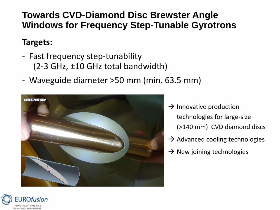
Targets:
- Fast frequency step-tunability (2-3 GHz, ±10 GHz total bandwidth)
- Waveguide diameter >50 mm (min. 63.5 mm)
Towards CVD-Diamond Disc Brewster Angle Windows for Frequency Step-Tunable Gyrotrons
Innovative production
technologies for large-size
(>140 mm) CVD diamond discs
Advanced cooling technologies
New joining technologies

54
Summary • DEMO requirements much more stronger than ITER
• But great progress in gyrotrons in last 20 years
1 MJ (0.5MW/1 sec) 1 GJ (1MW/1000 sec), eff. 30 55%
this brings some optimism
• Lack of long pulse operation experience with TL and
launchers
the experience will come soon
• Aims of the new developments are:
• Reliability of the system operation
• Higher power and higher frequency
• Multi-frequency operation
• Remote steering antenna
Thank you!