光源装置 MHAA-100W-D - MORITEXmoritex.com/assets/user_manual/manual_mhaa-100-d_series.pdf · 1...
28
光源装置 MHAA -100W-D (MHAA -100W-D -SC/SO :オプション) 取扱説明書 ご使用になる前に必ずお読みください。 Light Source Unit INSTRUCTION MANUAL Please read this instruction carefully, be 本製品を正しく安全にご使用いただき、お客様や他の方々への危害や財産への損害を未然に防止するために、この取 扱説明書では次のような表示をしています。表示の意味をよくご理解いただいてから本書をお読みください。 注意 この表示を無視して誤った取扱をすると、人が障害を負う可能性が想定される内容、および物 理的損害のみの発生が想定される内容を示しています。 高温 この表示を無視して誤った取扱をすると、人が障害を負う可能性が想定される内容を示してい ます。 使用上の注意 注意 ●本説明書に記載のない使用方法にてご使用の場合、性能が損なわれる場合があり ます。 ● AC 入力電圧は、AC 100/200系の各入力電圧範囲外で使用しない でください。 ● 点灯中は移動、振動、衝撃を与えない でください。 ● 点灯中は、溶剤や燃えやすいもの を本機の近くに置かないでください。 ● 点灯中は、冷却ファンの回転を確認し、ファンが止まった状態や吸気口、排気口がふ さがった状態で使用しない でください。 ● ランプの交換は、ランプ交換の方法をご確認のうえ行ってください 。 ● ランプハウスのフタは、必ず電源を切ってファンが止まっていることを確認してから開 ける ようにしてください。 ● 点灯中は光を直視しない でください。 高温 ● 点灯中や消灯直後はライトガイドロ金部分および本体上面が高温になっていますの で、触れないでください。 目次 使用上の注意..................表紙 用途・各部の名称および機能説明...... 1 主な機能..................... 2 設置方法.....................3 外部信号接続コネクタについて...... 4~5 ランプの交換................... 6 オプション.....................7~8 お手入れ.....................8 故障かなと思ったら............... 9 保証・アフターサービスについて....... 9 仕様........................10~11
Transcript of 光源装置 MHAA-100W-D - MORITEXmoritex.com/assets/user_manual/manual_mhaa-100-d_series.pdf · 1...
光源装置
MHAA-100W-D (MHAA-100W-D-SC/SO:オプション)
取扱説明書
ご使用になる前に必ずお読みください。
Light Source Unit
INSTRUCTION MANUAL
Please read this instruction carefully, before starting operation.
本製品を正しく安全にご使用いただき、お客様や他の方々への危害や財産への損害を未然に防止するために、この取扱説明書では次のような表示をしています。表示の意味をよくご理解いただいてから本書をお読みください。
注意
この表示を無視して誤った取扱をすると、人が障害を負う可能性が想定される内容、および物
理的損害のみの発生が想定される内容を示しています。
高温 この表示を無視して誤った取扱をすると、人が障害を負う可能性が想定される内容を示してい
ます。
使用上の注意
注意
● 本説明書に記載のない使用方法にてご使用の場合、性能が損なわれる場合があります。
● AC入力電圧は、AC100/200系の各入力電圧範囲外で使用しないでください。 ● 点灯中は移動、振動、衝撃を与えないでください。 ● 点灯中は、溶剤や燃えやすいものを本機の近くに置かないでください。 ● 点灯中は、冷却ファンの回転を確認し、ファンが止まった状態や吸気口、排気口がふ
さがった状態で使用しないでください。 ● ランプの交換は、ランプ交換の方法をご確認のうえ行ってください。 ● ランプハウスのフタは、必ず電源を切ってファンが止まっていることを確認してから開
けるようにしてください。 ● 点灯中は光を直視しないでください。
高温 ● 点灯中や消灯直後はライトガイドロ金部分および本体上面が高温になっていますの
で、触れないでください。
目次 使用上の注意.................. 表紙 用途・各部の名称および機能説明...... 1 主な機能..................... 2 設置方法..................... 3 外部信号接続コネクタについて...... 4~5
ランプの交換................... 6 オプション.....................7~8 お手入れ..................... 8 故障かなと思ったら............... 9 保証・アフターサービスについて....... 9 仕様........................10~11

1
用途 本装置は、ファイバ照明用の光源装置としてご使用いただけます。
各部の名称および機能説明
D-SUBVOLTAGE SELECTOR
AC INPUT
115
① ライトガイド口金
光ファイバのライトガイドを接続します。 ② ローレットビス
光ファイバのライトガイドを固定するためのビスです。 ③ 調光ツマミ
ランプの光量を可変するためのツマミです。⑤MANU/REMO切り
換えスイッチが「MANU」になっているときに、このつまみを回す
とランプの光量が変化します。 ④ 電源スイッチ
電源を入/切するためのスイッチです。「 l 」側に倒すと電源が
入ります。 ⑤ MANU/REMO 切り換えスイッチ
マニュアル調光と、外部信号による調光とを切り替えるスイッチ
です。外部信号で調光をする場合は「REMO」の位置にします。調
光ツマミでランプの光量を変える場合は「MANU」の位置にしてく
ださい。 ⑥ 電源表示灯
AC プラグに電源が供給された状態で、電源スイッチが ON にな
ると点灯します。 ⑦ LAMP ALARM 表示灯
ランプ切れ、またはランプ異常時に点灯します。 ⑧ 外部信号接続コネクタ
各種アラームモニタ信号や REMO 用信号入力用のコネクタです。
⑨ ファン排気口 冷却用ファンの排気口です。通風に十分注意してください。
⑩ ランプハウスフタ ランプ交換用のフタです。この中にハロゲンランプが収納されてい
ます。開閉前にランプ交換の注意を良くお読み下さい。 ⑪ ランプハウスフタ固定ラッチ
「OPEN」側に回すことでランプハウスフタを開くことができます。ラ
ンプ交換時以外はランプハウスフタを確実に閉め、固定ラッチを必
ず「CLOSE」側にして下さい。 ⑫ AC 電源インレット
AC 電源供給用プラグの差込です。 ⑬ 電圧切り替えスイッチ
AC 入力電圧の AC100/200 系の入力切り替えスイッチです。 ※【115】スイッチ表示:AC100-120V で使用してください。
※【230】スイッチ表示:AC200-240V で使用してください。 ※入力電圧設定を切り替えて使用される場合は、使用する国の法
律及び規格対応のACケーブルを使用してください ※ケーブル仕様として以下の条件のものを御使用ください。
・長さ3m以下、3線(L,N,PE)のケーブル、クラスⅠ TYPEの主
電源コードプラグ。
・光源装置の仕様にあった電圧、電流、温度範囲の物。

2
主な機能 ● マニュアル調光機能
前面にある調光つまみを使って、0~MAXまで連続に光量が調節できます。ただし、前面のMANU/REMO切り換えスイッチが「MANU」になっているときのみ有効です。
● リモート調光機能 前面のMANU/REMO切り換えスイッチが「REMO」のとき、後面の外部信号接続コネクタに8bitのデジタル信号を入カすることで、0~MAXまでの調光が可能です。接続のしかたについては5ページおよび8ページをご覧ください。
● ランプON/OFF機能 外部信号接続コネクタのランプON/OFF入力にDC5V-DC24Vの信号を入力することで、ランプを消灯できます。MANU/REMO切り換えスイッチに関係なく消灯できます。
● ランプ過電流検出機能※ ランプの過電流を検出し、電源を保護します。過電流が一定時間以上続いた場合、ランプ出力を遮断し、外部に信号を出力します。異常を検出した信号は、後面の外部信号接続コネクタに出力されます。
● 内部温度上昇の検出機能※ ランプ周辺の温度異常上昇を検知し、ランプへの電源供給を遮断し、外部に信号を出力します。異常を検出した信号は、後面の外部信号接続コネクタに出力されます。
● ランプ切れ検出機能※ ランプが切れたときなど、ランプに異常が発生した場合に外部に信号を出力します。
● ランプ異常表示※ ランプ過電流および、ランプ切れを検出した場合フロントパネルのLAMP ALARM表示灯が点灯します。
● シャッタ機能(オプション) 外部信号接続コネクタのシャッタON/OFF入力に DC24Vを入力することで、シャッタを動作できます。 MANU/REMO切り換えスイッチに関係なく動作できます。
「※」印の付いた機能が働いた場合、本機の電源を一度切って、
2~3秒後に再度電源を入れてください。

3
設置方法
注意
●本機は電源プラグがメイン遮断器となっておりますので、電源プラグの抜き差しが容易に行える場所に設
置してください。また電源スイッチがOFF状態で機械がスタンバイになっている場合、危険な充電部はござ
いません。
●本機の通風孔をふさがないで下さい。通風スペースを十分に確保しないと、本機の内部に熱がこもり、火
災の原因となることがあります。
水平な場所に設置し、本機周辺の通風スペースを以下のようにしてください。
※本体ゴム足を下にした水平設置。
水平な場所に設置し、周囲の通風スペースを充分に取るようにして下さい。
※ 最適スペース
※電源スイッチのON/OFFが容易に行える場所、あるいはインレットまたはプラグが容易に取り外せる場所に設置してく
ださい。
※感電保護:クラスⅠ機器(IEC60950-1)
※必ず接地して御使用ください。
ファンのエア方向 50mm 以上
本体上面の空気孔 30mm 以上
本体側面の空気孔 10mm 以上
本体底面の空気孔 9mm 以上

4
外部信号接続コネクタについて
注意
●外部信号接続コネクタには、コネクタに接続する機器の1次側(入力 AC)と完全に切り離された
信号線以外は接続しないでください。(IEC60950-1 による Class I I 機 器 )
●各接続ピンへの過大な入力や負荷は、光源の故障の原因となりますので十分ご注意ください。
●外部ケーブルはシールド線を使用してください。また、ケーブルの長さは2m 以下を推奨します。
●光源装置の電源 ON 時には、パネル VR 及び外部入力を最小にしておいてください。ランプへの
突入電流を防止することによりランプの劣化防止及びランプの寿命を緩和できます。
■インターフェース仕様
ピン番号 名 称 ピン番号 名 称
1 bit 0 (LSB) 9 COMMON(+)※1※2
2 bit 1 10 ランプON/OFF信号入力
3 bit 2 11 ランプ切れ (オープンエミッタ)
4 bit 3 12 ランプ過電流モニタ (オープンエミッタ)
5 bit 4 13 温度異常モニタ (オープンエミッタ)
6 bit 5 14 シャッタ ON/OFF入力※3 (DC24V)
7 bit 6 15 シャッタ ON/OFF入力※3 (GND)
8 bit 7 (MSB)
※ 1 DC5V - DC24Vでお使いいただけます。
※ 2 使用中の入力変動は行わないでください。
※ 3 オプション
■ ケーブル側コネクタ
光量を外部でコントロールする場合、コネクタ及びコネクタケースは下記のものをおすすめします。
● コネクタ(メス):HDAB-15S(05)(HRS 製)または相当品
● コネクタケース :HDA-CTH(HRS 製)または相当品
5
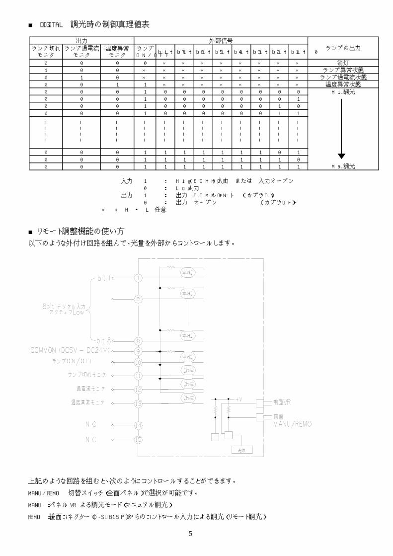
■ DIGITAL 調光時の制御真理値表
■リモート調整機能の使い方
以下のような外付け回路を組んで、光量を外部からコントロールします。
上記のような回路を組むと、次のようにコントロールすることができます。
MANU/REMO 切替スイッチ(全面パネル)で選択が可能です。
MANU:パネル VR よる調光モード(マニュアル調光)
REMO:後面コネクター(D-SUB15P)からのコントロール入力による調光(リモート調光)
ランプ切れモニタ
ランプ過電流モニタ
温度異常モニタ
ランプON/OFF bit 7 bit 6 bit 5 bit 4 bit 3 bit 2 bit 1 bit 0
0 0 0 0 × × × × × × × × 消灯1 0 0 × × × × × × × × × ランプ異常状態0 1 0 × × × × × × × × × ランプ過電流状態0 0 1 1 × × × × × × × × 温度異常状態0 0 0 1 0 0 0 0 0 0 0 0 Min.調光0 0 0 1 0 0 0 0 0 0 0 10 0 0 1 0 0 0 0 0 0 1 00 0 0 1 0 0 0 0 0 0 1 1
――
――
――
――
――
――
――
――
――
――
――
――
――
――
――
――
――
――
――
――
――
――
――
――
0 0 0 1 1 1 1 1 1 1 0 10 0 0 1 1 1 1 1 1 1 1 00 0 0 1 1 1 1 1 1 1 1 1 Max.調光
入力 1 : High(COMMON)入力 または 入力オープン0 : Low 入力
出力 1 : 出力 COMMONショート (カプラON)0 : 出力 オープン (カプラOFF)
× : H ・ L 任意
出力 外部信号ランプの出力

6
ランプの交換 ランプが切れたら新しいランプと交換します。
高温 ●以下のランプ交換作業前に、電源 ON の状態でランプを消灯させ、10分以上のファンによる強
制空冷を行ってください。点灯中または消灯直後のランプは大変高温になっていますので、手
をふれるとやけどの原因となることがあります。
注意
●ランプハウスフタを開ける前に必ず電源を切り、ファンが回転していないことを確認してくださ
い。また、ランプハウスフタを開けた状態では、絶対に電源を入れないでください。やけどや感
電あるいはファン接触によるけがの原因となることがあります。
●交換するランプは必ず指定のもの(LM-100)をお使いください。指定以外のものを使うと、火
災や使用ファイバの劣化等の原因となることがあります。
●交換ランプは落としたりしないでください。けがの原因となることがあります。
●ランプの内側を絶対にさわらないでください。もし誤ってさわった場合は、きれいな布やティッシ
ュペーパーでさわった部分をふいてください。アルコールを少し含ませると、よりきれいにふくこ
とができます。
1 本機上面にあるフタ固定ラッチを「OPEN」側に回
しフタを開けます。
2 レバーを矢印の方向に引くと、ランプが上に押し
上がります。
3 ランプを真上方向に持ち上げ、ランプホルダーか
ら外します。
4 ソケットを持ち、ランプをソケットから引き抜きま
す。
5 ランプホルダーのレバーを元の位置に戻してか
ら、新しいランプをホルダーに差し込みます。ラン
プの突起部分とランプホルダーのくぼみが合うよ
うに装着してください。
6 ランプにソケットを装着します。
7 ランプハウスのフタを元の状態に戻し、フタ固定
ラッチを「CLOSE」側に回します。
ランプソケットは古くなると接触抵抗が増加するために、新しいランプに交換しても十分な光量が得られなく
なることがあります。ランプソケットは、定期的に交換することをおすすめします。
交換する場合は、お買い上げの販売店または弊社営業所にご相談ください。

7
オプション 1. シャッタのタイプについて
シャッタには外部信号接続コネクタを使用しない時の状態により下記の2種類のものがあります。
SOタイプ・・・・・・光を遮りません(オープン)。
SCタイプ・・・・・・光を遮ります(クローズ)。
※製品がSOタイプかSCタイプかご確認の上、以下をお読みください。
2. シャッタの動作方法
オプションシャッタは、外部信号接続コネクタにDC0V またはDC24V を印加する事によりON/OFF 動作を行いま
す。
入力電圧 DC0V(OFF) DC24V(ON)
SO タイプ オープン クローズ SC タイプ クローズ オープン
3. 接続例
■参考ダイオード
ダイオード型番 :D1N60 (新電元工業株式会社)
定格 せん頭逆電圧:600 V
順電圧 :MAX 1.05 V
逆電流 :MAX 10 μA
出力電流 :1 A
または上記定格同等品。
⑭
⑮
光源装置
シャッター
24V
サージ吸収用ダイオードは接続されておりません。外付で接続する場合には点線内で示すようにダイオードを接続して使用してください。
b
a

8
4. 仕様
シャッタ仕様
開閉方式 メカニカル式(ロータリーソレノイド)
定格電圧/電流 DC 24 V / 0.32 A(Typ.)
シャッタ寿命 5000万回 ※1
連続通電時間 1時間以下 (20 ℃にて) ※2
反応時間 SO SC ON時間 25 mSec(max.) 開→閉 閉→開
OFF時間 30 mSec(max.) 閉→開 開→閉
ダイオードを接続した場合、シャッタ反応時間は仕様よりも遅くなります。
ダイオード接続時の反応時間(参考値) SO SC ON時間 30 mSec 開→閉 閉→開 OFF時間 45 mSec 閉→開 開→閉
注意 DC24 V 以上の過電圧を加えないでください。故障および劣化の原因となります。
お手入れ お手入れは定期的に行ってください
注意 ●お手入れをするときは必ず本機の電源を切り、光ファイバを外した状態で行なってください。
●中性洗剤以外はご使用にならないでください。シンナー・ベンジン・クレンザー・ナイロンたわし・
化学ぞうきんなどは、本体の表面を痛める原因となります。
● 吸気口やファンにほこりがたまった場合は、掃除
機のすきまノズルで吸い取ると簡単にきれいにな
ります。
● 本体の汚れは、乾いた布でふき取ってください。
汚れがひどいときは、布に薄めた中性洗剤を含
ませ、堅くしぼってから汚れをふき取ります。
※1. 当社平均寿命。 ※2. 1時間の連続通電後は、10分程度の間隔を置いてから再通電してください。

9
故障かなと思ったら 修理に出す前に、もう一度次の項目を確認してください。
症 状 原 因 対 策
電源を入れても動作しない。
(ランプがつかず、ファンも回らな
い)
● 電源プラグがコンセントから外
れていませんか?
● プラグをしっかりとコンセントに
差し込んでください。
電源を入れてもランプがつかない。
(ファンは回転する)
● ランプが切れていませんか?
● MANU/REMO 切り換えスイッチ
が「MANU」になっているとき
に、調光ツマミが0になっていま
せんか?
● ランプを交換してください。
● 調光ツマミを回して調光してくだ
さい。
ランプの光量が変化しない。 ● MANU/REMO 切り換えスイッチ
が「REMO」になっていません
か?
● スイッチを「MANU」にすると、調
光ツマミで調光できるようになり
ます。
ランプが一瞬(約3秒間)点灯して
消える。
● ランプが劣化していませんか? ● 新しいランプと交換してくださ
い。
保証・アフターサービスについて
● 本製品の保証期間はご購入日より1年間です。万
一、正常なご使用状態で保証期間中に故障が生じ
たときに限り、無償修理致します。(ただしランプは
除きます。)
● 保証期間後の修理は有償となります。修理によって
本製品の機能維持が可能と判断される場合は、お
客様のご要望により有償で修理いたします。
● 不明な点はご相談ください。
補修用品の詳細・アフターサービスについてご不明
な点は、お買い求めの販売店または弊社営業所に
遠慮なくお問い合わせください。
※ 修理を依頼される場合は、まず次のことをお知らせ
ください。
● 機 種 MHAA-100W-D
● 製造番号 本機上面に記載
● ご購入日 年 月 日
● 故障状態 できるだけ詳しく
● お名前(法人または個人名)、ご住所、電話番号

10
仕様 仕様および外観は、改良のため予告なく変更することがありますが、ご了承ください。
形 式 MHAA-100W-D MHAA-100W-D-SC/SO
回 路 方 式 PWM式スイッチングレギュレータ
入 力 電 圧 AC 100-120V/200-240V 50/60Hz
入力電圧切替方式※6
(光源背面パネルのスイッチ)
AC 100V系入力時:115表示側に設定。
AC 200V系入力時:230表示側に設定。
出 荷 時 設 定
AC 100V仕様 ・ 入力電圧切替スイッチ:115表示 ・ ACケーブル:MC-AC100A-2.0M
AC 200V仕様 ・ 入力電圧切替スイッチ:230表示 ・ ACケーブル:MC-AC200A-2.0M
入 力 電 流 (T y p i c a l ) 2.4A(AC 100 V系入力時) 1.2A(AC 200 V系入力時)
突 入 電 流 30A以下(AC100V入力、外気温25℃ コールドスタート時) 69A以下(AC230V入力、外気温25℃ コールドスタート時)
環 境 条 件
屋内使用、最大高度2000m 温度 0℃ ~ 45℃
31℃まで80% RH、40℃で50% RH に線形に低下 汚染度 2
設置カテゴリ Ⅱ
使 用 ラ ン プ ダイクロイックミラー付ハロゲンランプ
ラ ン プ 形 式 LM-100(12V、100W)
点 灯 方 式 直流点灯方式
ラ ン プ 電 圧 (標 準 ) DC 11.7V ±0.2V (Max時)
平 均 ラ ン プ 寿 命 公称 1000時間 (12.0V)
照 度 ※ 1 約30000 lx
色 温 度 ※ 2 約 3100 K
調 光 方 式 電圧可変式
外 部 調 光 機 能 有 (8bitデジタル信号入力)
保 護 機 能 ※ 3 過電流及び温度検知による出力カット 内臓ヒューズによる異常AC入力の遮断
シ ャ ッ タ ー 機 能 ( オ プ シ ョ ン )
- 有り
冷 却 方 式 ファンによる強制冷却
設 置 方 法 本体底部のゴム足を下にした水平設置
外 形 寸 法 ※ 4 74(W) × 118(H) × 244(D) mm
質 量 約2Kg
保 護 等 級 IP20 (IEC60529による)
マ ー キ ン グ ※ 5 EN61010-1:2001
EN61000-6-2:2001/EN55011:1998,A1:1999,A2:2002 によるCEマーキング
(注)仕様および外観は、改良のため予告なく変更することがありますが、ご了承ください。
※1 モリテックス標準ライトガイドを装着したとき、端面より50mm の位置での最大照度です。
※2 最大照度時のランプの色温度です。
※3 モニタ用外部出力が背面の外部信号接続コネクタに出力されます。

11
※4 突起部を含まない寸法です。
※5 本製品は光源装置単体での CE マーキング品です。その為、設置時に CE マーキング取得の AC ケーブルと
組み合わせて御使用下さい。
※6 入力電圧切替スイッチを【115】表示の設定でAC200V系入力を印加すると電源が破損するので絶対に避け
て下さい。また、AC230V表示側での設定でAC100V系入力を印加しても動作しません。
※7 使用環境温度が 40 ℃ 以上の場合、プラスチックファイバライトガイドは使用できません。また、40 ℃ 以下
の場合もライトガイドのファイバ結束径により石英アダプタ(KA-03)が必要になります。詳しいことはお問い
合わせ下さい。
■付属品
● 取扱説明書・・・・・・・・・・・・・・・・・・・・・・・・・・・・・・・・・・・1 部(本書)
● AC コードセット・・・・・・・・・・・・・・・・・・・・・・・・・・・・・・・・1 本 ※
※ 入力電圧仕様により添付ケーブルが異なります。
※ 使用する国や地域の規格への適合をご確認下さい。
※ 添付の AC コードセットは本光源装置専用の AC コードセット
です。本光源装置以外には、使用しないで下さい。
■ AC100V 仕様
● 適用 ① プラグ付き電源コードセット:電気用品安全法及び UL 規格、CSA 規格に適合。 ② アダプタ:電気用品安全法に適応。日本国以外では使用できません。
日本国以外の国で使用する場合はアダプタを取り外して下さい。 ● 型式:MC‐AC100A‐2.0M ● 外観図
1
2
■ AC200V 仕様
● 適用:欧州向けに使用するプラグ付き電源コードセット。 ● 注意事項:このプラグ付き電源コードセットは日本国内では使用できません。 ● 型式:MC‐AC200A‐2.0M ● 外観図

12
Memo

13
MHAA-100W-D
(incl. optional MHAA-100W-D-SC/SO)
Light Source Unit
INSTRUCTION MANUAL
Please read this instruction manual carefully, before starting operation.
Please carefully read the following information before using the unit. Following warning markings on the light source unit are explained in this instruction manual. The operator has to understand fully the meanings of the markings and the risks indicated through the markings, before starting operation.
CAUTION This warning marking indicates a condition that can result in hazard to the
operator or damage to the unit.
HOT This warning marking indicates a hot surface, which can lead to
burnings to the operator.
Precautions for use (CAUTION)
CAUTION
● The unit may be damaged if the equipment is used in a manner not specified in the instruction manual.
● Do not connect the unit to an input voltage outside the specified voltage ranges of AC100-120 V or AC200-240 V respectively.
● When the lamp is ON, be careful to protect the unit from vibration and hard impacts.
● When the lamp is ON, do not leave flammable materials or liquids around the unit.
● When the lamp is ON, confirm that the cooling fan is working and the air inlets are free and open.
● Before replacing the lamp, read carefully page 16 of this instruction manual: “Replacing the Lamp”.
● Before opening the lamp housing cover, be sure to switch the unit OFF and confirm that the fan has stopped.
● Do not look directly at the light source when it is ON. The high density-light can damage your eyes.
HOT
● Never touch the light guide connector, the ferrule and the upper part of the unit when the lamp is ON or short time after turning OFF. You might get burned as the lamp operates extremely hot.
Table of contents
Precautions for use ................13 Statement to intended use of the equipment
Name and Function of Each Part .......14 Features ...................... 15 Installation Method ................16
External Signal Connector ......... 17~19
Replacing the Lamp ...............20 Option .................... 21~22
Cleaning the equipment ............ 22 Troubleshooting ..................23 Warranty and Service...............23
General Specification............ 24~26

14
Statement to intended use of the equipment This unit is designed for use as a light source for fiber illumination.
Name and Function of Each Part
D-SUB
115
AC INPUT
VOLTAGE SELECTOR
① Light guide connector: Connection to the optical fiber light guide.
② Light guide ferrule fixing screw: Turn this knurled screw to fasten the light guide ferrule.
③ Intensity control: For adjusting the light intensity.
④ Power switch: ON/OFF. If the power switch is OFF, no hazardous voltage parts are touchable when opening the lamp room door for replacing the lamp. Before opening the lamp room door, read carefully page 16 of this manual (Replacing the lamp).
⑤ MANU / REMO selector switch: Using this switch, you can chose if the light intensity is adjusted manually or by an external signal. Select REMO for controlling the light intensity by an external signal. Select MANU for controlling it manually.
⑥ Power indicator: The light is ON when the power switch is ON.
⑦ Lamp alarm indicator: The light is ON when the lamp is blown, or in case of any other abnormality.
⑧ External signal connector (D-SUB): Connector for the REMO signal and the alarm signal. Be careful to switch the MANU / REMO switch to REMO if you want to use the connector for REMO signal.
⑨ Cooling fan: Be careful to keep at least 50mm of space to the rear of the equipment for adequate ventilation.
⑩ Lamp room (box) door: Only open this cover when replacing the lamp. Read page 16 of the instruction manual “Replacing the lamp” carefully.
⑪ Latch for lamp room door: Turn this latch to “OPEN”, for opening the lamp room (box) door (⑩).
⑫ AC power supply inlet: Connection to the AC power supply via power supply cord.
⑬ Voltage selection switch Switch for selecting the equipment supply voltage range (AC100/200)
※【 115 】 switch indication : Use it with AC100-120V. ※【 230 】 switch indication : Use it with AC200-240V. ※In case the input voltage setting different from the
initial setting is selected, use AC cable complying the regulations and standards of the country where the unit will be used.
※ Use the cable specifications conforming to the follwing conditions.
・ Three-wire (L, N and PE) cable with the length of 3m or less, and Class I Type main power code plug.
・ The cable with the voltage, current and temperature range conforming to the specifications of the Light Source Unit.

15
Features l Manual adjustment function of light intensity
The light intensity can be adjusted from 0 to MAX, by turning the light intensity control (3) on the front panel of the unit. This function is only activated, if the MANU / REMO selector switch (5) on the front panel of the unit is set to MANU.
l Adjustment of the light intensity by remote
control The light intensity can be adjusted from 0 to MAX, by inputting the relevant Bit sequence at the external signal connector on the rear panel of the unit (Pins 1-8). This function is only activated, if the MANU / REMO selector switch (5) on the front panel of the unit is set to REMO. See page 14-15 for detailed description of the external signal connector.
l Lamp ONIOFF function
The lamp can be turned ON / OFF by an external signal. When connecting a DC5V-24V signal to the external signal connector (8) the lamp turns OFF, regardless of the MANU / REMO setting. See page 14-15 for detailed description of the external signal connector.
l Detection of lamp-overcurrent * (Monitor available as option.) This function detects an overcurrent through the lamp and shuts down the power to the lamp, if this overcurrent flows continuously. Additionally, Pin
12 of the external signal connector (open circuit in normal condition) is internally short-circuited to COMMON (Interface to user).
l Detection of internal temperature rise *
(Monitor available as option.) This function detects an abnormal temperature rise in the vicinity of the lamp, and shuts down the power to the lamp. Additionally, Pin 13 of the external signal connector (open circuit in normal condition) is internally short-circuited to COMMON (Interface to user).
l Monitoring function for abnormal lamp-state *
This function sets a signal in case of an abnormal lamp-state, for example if the lamp goes open circuit. This signal is put out at the external signal connector (8) at the rear panel of the unit. (Pin 11 of the external signal connector (open circuit in normal condition) is internally short-circuited to COMMON). The power to the lamp is not shut down.
l Shutter function (option)
The (optional) shutter function (MHAA-100W-DSC/DSO) does operate when a DC24V signal is connected to the Shutter ON/OFF input of the external signal connector. This function does operate regardless of the MANU / REMO setting.
(*) indicates that the unit will stop operating. For
resetting the unit, switch it OFF, wait for 3 seconds and then switch it ON again.

16
Installation Method
Caution
●The power plug breaks the mains supply to the unit. Be sure to connect the plug
in such a way that it can be pulled out easily, in case of emergency.
●Provide adequate space for ventilation because otherwise the light source may
malfunction or cause fire.
Install the unit in such a way, that adequate space is left free for ventilation.
※Horizontal installation with the rubber feet of the unit at the bottom
Install the unit at a horizontal place and secure enough peripheral space for ventilation.
※ Optimum Space
※ Install the unit at such a place where the power switch can be easily turned on or off,or where the inlet or
the plug can be easily removed.
※Protection from electric shock:Class I Equipment(iec60950-1)
※Always connect the unit to ground before use.
Direction of air flow: Keep at least 50 mm Air holes at top of unit: Keep at least 30 mm Air holes at side of unit: Keep at least 10 mm
Air holes at bottom of unit: Keep at least 9 mm

17
External Signal Connector
Caution
●Only SELV circuits, which have reinforced insulation to their equipment primary
circuit may be connected to the external signal connector. (SELV according to
EN60950-1)
●Be careful not to apply an excessively large input or load to the connection pins,
because otherwise the light source might get damaged.
●Use a shielded cable with a length not exceeding 2m for external connection.
●Make sure that the panel VR and the external inputs are at their minimum
settings when the light source unit is ON. This extends lamp life and prevents
deterioration of the lamp performance.
■ Interface Specifications
Pin No. Function Pin No. Function
1 Bit 1 (LSB) 9 COMMON (+) input※1※2
2 Bit 2 10 Lamp ON/OFF signal input
3 Bit 3 11 Lamp off signal (Open Emitter)
4 Bit 4 12 Over current monitor (Open Emitter)
5 Bit 5 13 Abnormal temperature signal (Open Emitter)
6 Bit 6 14 Shutter ON/OFF input ※3 (DC24V)
7 Bit 7 15 Shutter ON/OFF input ※3
(GND)
8 Bit 8 (MSB)
※ 1 Supply 5 Vdc – 24 Vdc to this pin
※ 2 Do not change the input voltage during use
※ 3 Option
■ External Cable (side) connector When controlling the light intensity of the lamp by external signal, only use connector types, which are indicated on below.
l Connector (female): HDAB-15S (made by HRS) or equivalent
l Connector case: HDA-CTH (made by HRS) or equivalent

18
■ How to use the remote control function For controlling the light intensity of the lamp by external signal, please follow the instructions as shown below.
Following kinds of controls are possible when connecting like shown above. Use the MANU / REMO switch
on the front panel of the unit.
MANU: Adjust the light intensity by using the panel VR.
REMO: Adjust the light intensity by external signal, connected to the external signal connector at the rear
panel of the unit. (D-SUB 15P)
NC
NC
19
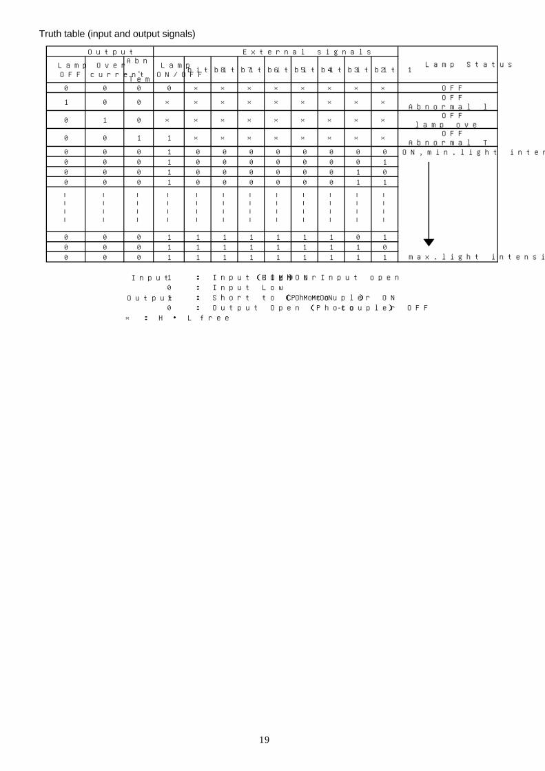
Truth table (input and output signals)
LampOFF
Overcurrent
Abnorm.
Temp.
LampON/OFF
bit 8 bit 7 bit 6 bit 5 bit 4 bit 3 bit 2 bit 1
0 0 0 0 × × × × × × × × OFF
1 0 0 × × × × × × × × × OFFAbnormal lamp state
0 1 0 × × × × × × × × × OFFlamp overcurrent
0 0 1 1 × × × × × × × × OFFAbnormal Temp. Rise
0 0 0 1 0 0 0 0 0 0 0 0 ON,min.light intensity0 0 0 1 0 0 0 0 0 0 0 10 0 0 1 0 0 0 0 0 0 1 00 0 0 1 0 0 0 0 0 0 1 1
――
――
――
――
――
――
――
――
――
――
――
――
――
――
――
――
――
――
――
――
――
――
――
――
0 0 0 1 1 1 1 1 1 1 0 10 0 0 1 1 1 1 1 1 1 1 00 0 0 1 1 1 1 1 1 1 1 1 max.light intensity
Input 1 : Input High(COMMON) or Input open0 : Input Low
Output 1 : Short to COMMON (Photo-coupler ON)0 : Output Open (Photo-coupler OFF)
× : H ・ L free
Output External signals
Lamp Status

20
Replacing the Lamp If the lamp is blown, replace it only with the same type of lamp.
HOT
●Before replacing the lamp, be sure that the lamp is OFF and the power
switch is ON for at least 10 minutes before replacing the lamp. The lamp is
very hot, and touching it before it has cooled down sufficiently can cause you
burns.
CAUTION
●Before opening the lamp room door, be sure to switch the unit OFF (power
switch) and confirm that the fan stops. Never turn ON the power switch when
the lamp room door is opened. Danger of electric shock, burns and injury
due to moving fan.
●Confirm to use the specified lamp (LM-100) before replacement, because
otherwise the fiber characteristics will change to the worse.
●Be careful not to drop the lamp when replacing it.
●Never touch the lamp bulb with bare hands. Even small amounts of grease
or other impurities can cause failure of the lamp as it heats up.
1 Turn the latch of the lamp room door to “OPEN”,
then open the lamp housing cover.
2 Gently pull the lever following the arrow to slide
the lamp fixed in the lamp holder.
3 Carefully remove the blown lamp from the holder.
4 Pull out the lamp from the socket.
5 Carefully slide the new lamp down into the
lamp holder and set the lever to the original
position. Before fixing the lamp, ensure that the
projection on lamp coincides with the
depression in holder.
6 Keep pushing the socket to the lamp until it fixes
in firmly.
7 Return the lamp room door to its original position,
and then turn the latch to “CLOSE”.
NOTE:
When the lamp socket becomes old, the contact resistance increases and the light intensity may
get reduced. For this reason, the lamp socket should be replaced at regular intervals. Have this
work be done by the shop where you purchased the unit or by the nearest Moritex sales office.
Lamp Projection on lamp
Depression in holder
Lamp holder
Socket Lamp
Lamp holder Lever

21
Option 1. MHAA-100W-SC/SO
There are two kinds of shutters, which have following states, when the signal at the external signal
connector is LOW.
SO type ・・・・・・ Shutter Open, the light projection is not shut.
SC type ・・・・・・ Shutter Close, the light projection is shut.
※ Please read the following information after confirming the type of the shutter (SO or SC).
2. Shutter operation The optional shutter is operated by putting in a voltage of 24V/0V to the Shutter ON/OFF input of the
external signal connector.
Input voltage 0 V(OFF) 24 V(ON) SO type Open Close SC type Close Open
3. Connection example
■ Diode specifications (example) l Diode: D1N60 (made by SHINDENGEN) or equivalent
Reverse Voltage: 600 V
Forward Voltage: MAX 1.05 V
Reverse Current: MAX 10 µA
Forward Current: 1 A
4. Specifications 4.1. Interface specifications (External Signal Connector)
Pin number Name 14 Shutter ON/OFF signal (+24 V) 15 Shutter ON/OFF signal (GND)
⑭
⑮ 24V
b
a
Lighting Unit
Shutter
There is no diode for surge protection connected internally. For connecting an external diode, please refer to the schematic above and to diode specifications below.
Connection example

22
4. 2. Shutter specifications
Opening and closing method Mechanical type (rotary solenoid) Standard voltage / current DC 24 V / 0.32 A (typ.) Operating temperature / humidity 0-40 ℃ / 20-80 % RH
Lifetime 50.000.000 times ※1 Max. continuous operation 1 hour (at 20 ℃) ※2
Response time SO SC ON time 25 ms (max.) open→close close→open OFF time 30 ms (max.) close→open open→close
The shutter response time becomes longer (the shutter speed becomes slower) when the diode for
surge protection is installed.
Response time with diode connection (reference value) SO SC
ON time 30 ms open→close close→open OFF time 45 ms close→open open→close
※1. Average lifetime (according to our experience)
※2. Please turn OFF the shutter for about 10 minutes after the shutter is continuously ON for an hour.
Caution ● Please do not input a voltage above 24V because it causes troubles and
deteriorations.
Cleaning the equipment Clean the unit periodically.
Caution
●Before cleaning the unit, be sure to switch OFF the unit and disconnect the
optical fiber.
●Do not use anything else than a neutral detergent for cleaning the device.
Thinner, benzene and household cleaner may damage the unit.
l If dust accumulates at the air inlet or on the fan, use the crevice nozzle of a vacuum cleaner.
l If the contamination is worse, wipe it off with a cloth that has been lightly immersed in a weak solution of
neutral detergent.

23
Troubleshooting Before requesting repair, check the following items.
Symptom Cause Remedy
The lamp does not switch ON.
(Neither lamp nor fan do work.)
● Check the power plug, for
correct plug-in.
● Insert the plug correctly into
the power outlet.
The lamp does not light when the
unit is switched ON.
(The fan does work.)
● The lamp might be blown.
● Check the light intensity
control.
● Replace the lamp according to
the instruction manual.
● Rotate the light intensity
control to adjust the light
intensity.
The light intensity of the lamp does
not change.
● Check the MANU / REMO
selector switch.
● The light intensity can be
adjusted manually, only if the
MANU / REMO selector switch
is set to MANU.
The lamp lights only momentarily
(about 3 seconds) and then goes
out again.
● The lamp may have blown ● Replace the lamp with a new
one. Refer to the instruction
manual for the lamp replacing
procedure.
Warranty and Service
● The warranty of this product lasts for one year
from the date of purchase. In case of product
failure within one year from the date of purchase,
and there is no doubt on the correct utilization of
the product, according to this instruction manual
the unit will be repaired at no charge. The lamp
is excluded from this service.
● Repairs on the product, later than one year from
the date of purchase will be charged. In case of
maintenance, the product will be repaired for
any defective parts, if the customer requests it.
These repairs will be charged.
● Please feel free to contact Moritex, if anything
remains unclear.
If you have any questions regarding parts or
service, please contact your dealer or an
authorized MORITEX service center.
※ Please provide following information when
requesting service.
● Model: MHAA-100W-D
● Manufacturing number: Indicated on the top
of the unit.
● Date of purchase:
● Breakdown state: Please provide
detailed information
● Your name (company name and/or individual
name), address, telephone/FAX number

ES0570AE.doc 24
General Specification The specifications of this unit may be changed without prior notice.
I tem MHAA-100W-D MHAA-100W-D-SC/SO
Circuit method PWM regulated switching type
Input source AC 100-120V / 200-240V 50/60Hz Input voltage range
select ion※6 (Voltage selector switch on the rear
panel)
Voltage selection switch indicates “115”: Input Voltage Range: AC 100-120V
Voltage selection switch indicates “230”: Input Voltage Range: AC 200-240V
Factory Setting
Specification of AC 100V ・ Input Voltage Selection Switch: “115”is indicated. ・ AC Cable:MC-AC100A-2.0M
Specification of AC 200V ・ Input Voltage Selection Switch: “230”is indicated. ・ AC Cable:MC-AC200A-2.0M
Input current
(Typical)
2.4A ( in AC 100 V mode)
1.2A ( in AC 200 V mode)
Rush current Less than 30A (Input Voltage: AC100V, air temperature 25℃, cold start)
Less than 69A (Input Voltage: AC230V, air temperature 25℃, cold start)
Environmental conditions
Indoor use
Altitude up to 2000m Temperature 0℃ to 45℃
Maximum relative humidity 80% for temperatures up to 31℃ decreasing linearly to 50% relative humidity at 40℃
Pol lut ion degree 2 Instal lat ion category 2
Operat ing lamp Halogen lamp with dichroic ref lector
LM-100 (12V, 100W)
Lamp method DC voltage
Lamp source (standard) 11.7 Vdc ±0.2V (Max.)
Lamp l i fe Normal: 1000 hours (12.0V)
I l luminance※1 Approx. 30000 lx
Color temp.※2 Approx. 3100 K
Light intensity method Variable voltage type
External light intensity Adjustment function Yes ( 8bit digital signal )
Protection function※3 Output cutoff : Overload detector, temperature fuse
Input cutoff : Overload detector, internal fuse
Shutter funct ion Option - Yes
Cool ing method Forced cool ing, using fan (forced air cool ing)
Instal lat ion method Instal l horizontal ly on the rubber feet at the bottom of the unit
Dimensions※4 74(W) x 118(H) x 244(D) mm
Weight Approx. 2kg IP code IP20 (By IEC60529)
CE marking※5 Harmonized : EN61000-6-2:2001/EN55011:1998,A1:1999,A2:2002
EN61010-1: 2001

ES0570AE.doc 25
NOTE:
※1 Measured value, 50mm from the edge of the unit. Standard Moritex light guide is installed; color
temperature is at maximum value.
※2 Maximum color temperature of the lamp.
※3 Output signals to external signal connector.
※4 Dimensions do not include the projection part.
※5 The MHAA-100W-D, MHAA-100W-D-SC/DSO are CE marked according to the Low Voltage Directive, EMC
Directive. The user has to make sure that all external equipment (incl. the power supply cable), connected
to this device also do conform to the relevant EU Directives and are adequately tested to applicable, valid
EN standards.
※6 Be careful to connect the right voltage to the relevant Input Voltage Range determined by the position of the
Voltage Selection Switch. If you connect a wrong voltage the equipment might be damaged because of
overvoltage or might not work because of undervoltage.
※7 In the operating temperature exceeds 40℃, the plastic fiber light guide cannot be used. Even if the
temperature is lower than 40℃, the quartz adopter (KA-03) is required depending on the fiber bundle
diameter of the light guide. For the details, please contact us.
■ Accessories ● Instruction Manual ・・・・・・・・・・・・・・・・・・・・・・・・・・・1 (This book) ● AC Code Set ・・・・・・・・・・・・・・・・・・・・・・・・・・・・・・・・1 ※
※ The attached cable varies depending on the input voltage specification.
※You are requested to confirm the compliance with the standard applicable to a country or region where the unit will be used.
※ An attached AC cord set is an AC cord set for exclusive use of this source of Light Source Unit. Other than this source of Light Source Unit, please do not use it.
■ Specification of AC100V
● Application ① Power Code Set with Plug: Complies with the Electrical Appliance and Material Safety Law and UL
and CSA Standards. ② Adapter: Complies with Complies with the Electrical Appliance and Material Safety Law. Unusable
outside Japan. If the unit is used in any nation other than Japan, remove the adapter. ● Type:MC-AC100A-2.0M ● External View
1
2
ES0570AE.doc 26
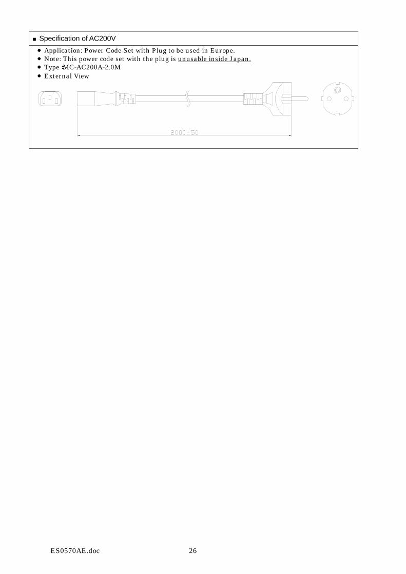
■Specification of AC200V
● Application: Power Code Set with Plug to be used in Europe. ● Note: This power code set with the plug is unusable inside Japan. ● Type:MC-AC200A-2.0M ● External View

ES0570AE.doc 27
カスタマーサービスセンター TEL: 045-909-4705 FAX: 045-909-4707
東京支店TEL: 03-3401-9756 FAX: 03-3401-9757
京都支店TEL: 075-223-3801 FAX: 075-223-3807
Head office international division(International Grp.)
TEL: +81-3-3401-9717 FAX: +81-3-3401-8063
MORITEX U.S.A. INC.TEL: +1-408-363-2100 FAX: +1-408-363-9980
MORITEX EUROPE LTD.TEL: +44-01223-301148 FAX: +44-01223-301149
MORITEX(Hong Kong)Co. Ltd. TEL: +852-2439-0968 FAX: +852-2439-0377
株式会社モリテックスhttp://www.moritex.co.jp
6862 Santa Teresa Blvd., San Jose, CA 95119, USA
14 Signet Court, Swanns Road, Cambridge CB5 8LA, United Kingdom
3F Richwealth Industrial Bldg., 77-87 Wang Lung Street Tsuen Wan,New Territories, Hong Kong
3-1-14Jingu-mae, Shibuya-ku, Tokyo, 115-0001 Japan
〒150-0001 東京都渋谷区神宮前3-1-14 モリテックス本社ビル
〒604-8277 京都府京都市中京区西洞院通姉小路上ル
MORITEX CORPORATION
株式会社 モリテックス


![非常用ディーゼル 発電装置 - dhtd.co.jp · 2 3 非常時における安定した電源供給に備える 地球にやさしいダイハツディーゼル発電装置 [陸用]非常用ディーゼル発電装置](https://static.fdocuments.net/doc/165x107/5b729c0b7f8b9aa04c8cde26/-dhtdcojp-2-3-.jpg)