Eaton 9395 UPS 225 - 275 kVA / 300kVAPF0.8 User's and ...
133
Eaton 9395 UPS 225 - 275 kVA / 300kVAPF0.8 User’s and Installation Guide
Transcript of Eaton 9395 UPS 225 - 275 kVA / 300kVAPF0.8 User's and ...

Eaton 9395 UPS
225 - 275 kVA / 300kVAPF0.8
User’s and Installation Guide

IMPORTANT SAFETY INSTRUCTIONSSAVE THESE INSTRUCTIONS
This manual contains important instructions that you should follow during installation and maintenance of the UPS and batteries. Please read all instructions before operating the equipment and save this manual for future reference.
This is a product for commercial and industrial application in the second environment.
Installation restrictions or additional measures may be needed to prevent disturbances.
©2010 Eaton Corporation
All Rights Reserved
The contents of this manual are the copyright of the publisher and may not be reproduced (even extracts) unless permission granted.Every care has been taken to ensure the accuracy of the information contained in this manual, but no liability can be accepted for any errors or omission. The right to make design modifications is reserved.
1 Introduction . . . . . . . . . . . . . . . . . . . . . . . . . . . . . . . . . . . . . . . . . . . . . . . . . . . . . . . . . . . . . . . . . . . . . . . . . . . . . . . . . . . . . . . . . . 11.1 UPS standard features . . . . . . . . . . . . . . . . . . . . . . . . . . . . . . . . . . . . . . . . . . . . . . . . . . . . . . . . . . . . . . . . . . . . . . . . . . . . . . . 1
1.1.1 Installation features . . . . . . . . . . . . . . . . . . . . . . . . . . . . . . . . . . . . . . . . . . . . . . . . . . . . . . . . . . . . . . . . . . . . . . . . . 11.1.2 Control panel . . . . . . . . . . . . . . . . . . . . . . . . . . . . . . . . . . . . . . . . . . . . . . . . . . . . . . . . . . . . . . . . . . . . . . . . . . . . . . . 11.1.3 Customer Interface . . . . . . . . . . . . . . . . . . . . . . . . . . . . . . . . . . . . . . . . . . . . . . . . . . . . . . . . . . . . . . . . . . . . . . . . . . 31.1.4 Advanced Battery Management . . . . . . . . . . . . . . . . . . . . . . . . . . . . . . . . . . . . . . . . . . . . . . . . . . . . . . . . . . . . . . . . 31.1.5 Power Management Software . . . . . . . . . . . . . . . . . . . . . . . . . . . . . . . . . . . . . . . . . . . . . . . . . . . . . . . . . . . . . . . . . 3
1.2 Options and accessories . . . . . . . . . . . . . . . . . . . . . . . . . . . . . . . . . . . . . . . . . . . . . . . . . . . . . . . . . . . . . . . . . . . . . . . . . . . . . . 31.2.1 Integrated battery cabinet . . . . . . . . . . . . . . . . . . . . . . . . . . . . . . . . . . . . . . . . . . . . . . . . . . . . . . . . . . . . . . . . . . . . 31.2.2 Field Installed UPM. . . . . . . . . . . . . . . . . . . . . . . . . . . . . . . . . . . . . . . . . . . . . . . . . . . . . . . . . . . . . . . . . . . . . . . . . . 31.2.3 Maintenance Bypass Module . . . . . . . . . . . . . . . . . . . . . . . . . . . . . . . . . . . . . . . . . . . . . . . . . . . . . . . . . . . . . . . . . . 31.2.4 Sync Control . . . . . . . . . . . . . . . . . . . . . . . . . . . . . . . . . . . . . . . . . . . . . . . . . . . . . . . . . . . . . . . . . . . . . . . . . . . . . . . 41.2.5 Single-feed kit . . . . . . . . . . . . . . . . . . . . . . . . . . . . . . . . . . . . . . . . . . . . . . . . . . . . . . . . . . . . . . . . . . . . . . . . . . . . . . 41.2.6 Distributed Bypass System . . . . . . . . . . . . . . . . . . . . . . . . . . . . . . . . . . . . . . . . . . . . . . . . . . . . . . . . . . . . . . . . . . . . 41.2.7 Input Output Module configuration . . . . . . . . . . . . . . . . . . . . . . . . . . . . . . . . . . . . . . . . . . . . . . . . . . . . . . . . . . . . . 41.2.8 Inherent redundancy . . . . . . . . . . . . . . . . . . . . . . . . . . . . . . . . . . . . . . . . . . . . . . . . . . . . . . . . . . . . . . . . . . . . . . . . . 41.2.9 Energy Saver and High Alert modes . . . . . . . . . . . . . . . . . . . . . . . . . . . . . . . . . . . . . . . . . . . . . . . . . . . . . . . . . . . . . 51.2.10 Variable Module Management System and High Alert modes . . . . . . . . . . . . . . . . . . . . . . . . . . . . . . . . . . . . . . . . 51.2.11 Optional X-Slot cards . . . . . . . . . . . . . . . . . . . . . . . . . . . . . . . . . . . . . . . . . . . . . . . . . . . . . . . . . . . . . . . . . . . . . . . . 5
1.3 Basic system configurations . . . . . . . . . . . . . . . . . . . . . . . . . . . . . . . . . . . . . . . . . . . . . . . . . . . . . . . . . . . . . . . . . . . . . . . . . . . 51.4 Using this manual . . . . . . . . . . . . . . . . . . . . . . . . . . . . . . . . . . . . . . . . . . . . . . . . . . . . . . . . . . . . . . . . . . . . . . . . . . . . . . . . . . . 61.5 Conventions used in this manual . . . . . . . . . . . . . . . . . . . . . . . . . . . . . . . . . . . . . . . . . . . . . . . . . . . . . . . . . . . . . . . . . . . . . . . 61.6 Symbols, controls, and indicators . . . . . . . . . . . . . . . . . . . . . . . . . . . . . . . . . . . . . . . . . . . . . . . . . . . . . . . . . . . . . . . . . . . . . . . 71.7 For more information. . . . . . . . . . . . . . . . . . . . . . . . . . . . . . . . . . . . . . . . . . . . . . . . . . . . . . . . . . . . . . . . . . . . . . . . . . . . . . . . . 71.8 Getting help. . . . . . . . . . . . . . . . . . . . . . . . . . . . . . . . . . . . . . . . . . . . . . . . . . . . . . . . . . . . . . . . . . . . . . . . . . . . . . . . . . . . . . . . 7
2 Safety warnings. . . . . . . . . . . . . . . . . . . . . . . . . . . . . . . . . . . . . . . . . . . . . . . . . . . . . . . . . . . . . . . . . . . . . . . . . . . . . . . . . . . . . . . 83 UPS installation plan and unpacking . . . . . . . . . . . . . . . . . . . . . . . . . . . . . . . . . . . . . . . . . . . . . . . . . . . . . . . . . . . . . . . . . . . 10
3.1 Creating an installation plan. . . . . . . . . . . . . . . . . . . . . . . . . . . . . . . . . . . . . . . . . . . . . . . . . . . . . . . . . . . . . . . . . . . . . . . . . . 103.2 Preparing the site . . . . . . . . . . . . . . . . . . . . . . . . . . . . . . . . . . . . . . . . . . . . . . . . . . . . . . . . . . . . . . . . . . . . . . . . . . . . . . . . . . 10
3.2.1 Environmental and installation considerations . . . . . . . . . . . . . . . . . . . . . . . . . . . . . . . . . . . . . . . . . . . . . . . . . . . 113.2.2 UPS system power wiring preparation . . . . . . . . . . . . . . . . . . . . . . . . . . . . . . . . . . . . . . . . . . . . . . . . . . . . . . . . . . 163.2.3 UPS system interface wiring preparation. . . . . . . . . . . . . . . . . . . . . . . . . . . . . . . . . . . . . . . . . . . . . . . . . . . . . . . . 203.2.4 Distributed bypass power wiring preparation . . . . . . . . . . . . . . . . . . . . . . . . . . . . . . . . . . . . . . . . . . . . . . . . . . . . 21
3.3 Inspecting and unpacking the UPS cabinet . . . . . . . . . . . . . . . . . . . . . . . . . . . . . . . . . . . . . . . . . . . . . . . . . . . . . . . . . . . . . . 224 UPS system installation . . . . . . . . . . . . . . . . . . . . . . . . . . . . . . . . . . . . . . . . . . . . . . . . . . . . . . . . . . . . . . . . . . . . . . . . . . . . . . . 24
4.1 Preliminary installation information . . . . . . . . . . . . . . . . . . . . . . . . . . . . . . . . . . . . . . . . . . . . . . . . . . . . . . . . . . . . . . . . . . . . 244.2 Unloading the UPS cabinet from the pallet and mechanical installation . . . . . . . . . . . . . . . . . . . . . . . . . . . . . . . . . . . . . . . 244.3 Field installed UPM (FI-UPM) installation. . . . . . . . . . . . . . . . . . . . . . . . . . . . . . . . . . . . . . . . . . . . . . . . . . . . . . . . . . . . . . . . 274.4 Battery cabinet installation. . . . . . . . . . . . . . . . . . . . . . . . . . . . . . . . . . . . . . . . . . . . . . . . . . . . . . . . . . . . . . . . . . . . . . . . . . . 274.5 Distributed bypass tie cabinet installation. . . . . . . . . . . . . . . . . . . . . . . . . . . . . . . . . . . . . . . . . . . . . . . . . . . . . . . . . . . . . . . 274.6 Installing UPS external and battery power wiring . . . . . . . . . . . . . . . . . . . . . . . . . . . . . . . . . . . . . . . . . . . . . . . . . . . . . . . . . 29
4.6.1 External power wiring installation . . . . . . . . . . . . . . . . . . . . . . . . . . . . . . . . . . . . . . . . . . . . . . . . . . . . . . . . . . . . . 294.6.2 Battery wiring . . . . . . . . . . . . . . . . . . . . . . . . . . . . . . . . . . . . . . . . . . . . . . . . . . . . . . . . . . . . . . . . . . . . . . . . . . . . . 32
4.7 Installing interface connections . . . . . . . . . . . . . . . . . . . . . . . . . . . . . . . . . . . . . . . . . . . . . . . . . . . . . . . . . . . . . . . . . . . . . . . 334.7.1 TB1, TB2, and TB3 connections (other than TB1 battery interface connections) . . . . . . . . . . . . . . . . . . . . . . . . . . 334.7.2 TB1 battery interface connections . . . . . . . . . . . . . . . . . . . . . . . . . . . . . . . . . . . . . . . . . . . . . . . . . . . . . . . . . . . . . 384.7.3 X-Slot connections . . . . . . . . . . . . . . . . . . . . . . . . . . . . . . . . . . . . . . . . . . . . . . . . . . . . . . . . . . . . . . . . . . . . . . . . . 39
4.8 Installing a remote EPO switch. . . . . . . . . . . . . . . . . . . . . . . . . . . . . . . . . . . . . . . . . . . . . . . . . . . . . . . . . . . . . . . . . . . . . . . . 414.9 Installing options, accessories, and distributed bypass control wiring . . . . . . . . . . . . . . . . . . . . . . . . . . . . . . . . . . . . . . . . . 444.10 Initial startup. . . . . . . . . . . . . . . . . . . . . . . . . . . . . . . . . . . . . . . . . . . . . . . . . . . . . . . . . . . . . . . . . . . . . . . . . . . . . . . . . . . . . . 444.11 Completing the installation checklist . . . . . . . . . . . . . . . . . . . . . . . . . . . . . . . . . . . . . . . . . . . . . . . . . . . . . . . . . . . . . . . . . . . 44
5 Installing options and accessories . . . . . . . . . . . . . . . . . . . . . . . . . . . . . . . . . . . . . . . . . . . . . . . . . . . . . . . . . . . . . . . . . . . . . 455.1 Installing an optional HotSync CAN Bridge Card . . . . . . . . . . . . . . . . . . . . . . . . . . . . . . . . . . . . . . . . . . . . . . . . . . . . . . . . . . 455.2 Installing distributed bypass control wiring . . . . . . . . . . . . . . . . . . . . . . . . . . . . . . . . . . . . . . . . . . . . . . . . . . . . . . . . . . . . . . 47
6 Understanding UPS operation. . . . . . . . . . . . . . . . . . . . . . . . . . . . . . . . . . . . . . . . . . . . . . . . . . . . . . . . . . . . . . . . . . . . . . . . . . 526.1 Looking inside the UPS system. . . . . . . . . . . . . . . . . . . . . . . . . . . . . . . . . . . . . . . . . . . . . . . . . . . . . . . . . . . . . . . . . . . . . . . . 526.2 Single UPS. . . . . . . . . . . . . . . . . . . . . . . . . . . . . . . . . . . . . . . . . . . . . . . . . . . . . . . . . . . . . . . . . . . . . . . . . . . . . . . . . . . . . . . . 53
6.2.1 Modes . . . . . . . . . . . . . . . . . . . . . . . . . . . . . . . . . . . . . . . . . . . . . . . . . . . . . . . . . . . . . . . . . . . . . . . . . . . . . . . . . . . 536.2.2 Normal mode. . . . . . . . . . . . . . . . . . . . . . . . . . . . . . . . . . . . . . . . . . . . . . . . . . . . . . . . . . . . . . . . . . . . . . . . . . . . . . 536.2.3 Bypass mode . . . . . . . . . . . . . . . . . . . . . . . . . . . . . . . . . . . . . . . . . . . . . . . . . . . . . . . . . . . . . . . . . . . . . . . . . . . . . . 556.2.4 Variable Module Management System . . . . . . . . . . . . . . . . . . . . . . . . . . . . . . . . . . . . . . . . . . . . . . . . . . . . . . . . . 566.2.5 Energy Saver System (ESS) . . . . . . . . . . . . . . . . . . . . . . . . . . . . . . . . . . . . . . . . . . . . . . . . . . . . . . . . . . . . . . . . . . . 566.2.6 Battery mode. . . . . . . . . . . . . . . . . . . . . . . . . . . . . . . . . . . . . . . . . . . . . . . . . . . . . . . . . . . . . . . . . . . . . . . . . . . . . . 57
6.3 UPS system oneline configurations . . . . . . . . . . . . . . . . . . . . . . . . . . . . . . . . . . . . . . . . . . . . . . . . . . . . . . . . . . . . . . . . . . . . 596.4 Multiple UPS distributed bypass system . . . . . . . . . . . . . . . . . . . . . . . . . . . . . . . . . . . . . . . . . . . . . . . . . . . . . . . . . . . . . . . . 62
6.4.1 Multiple UPS parallel system modes . . . . . . . . . . . . . . . . . . . . . . . . . . . . . . . . . . . . . . . . . . . . . . . . . . . . . . . . . . . 62
1027212 UPS 225 - 275 kVA/300kVAPF0.8 iRevision E User’s and Installation Guide

6.4.2 Normal mode – distributed bypass. . . . . . . . . . . . . . . . . . . . . . . . . . . . . . . . . . . . . . . . . . . . . . . . . . . . . . . . . . . . . 636.4.3 Bypass mode – distributed bypass . . . . . . . . . . . . . . . . . . . . . . . . . . . . . . . . . . . . . . . . . . . . . . . . . . . . . . . . . . . . . 646.4.4 Battery mode – distributed bypass. . . . . . . . . . . . . . . . . . . . . . . . . . . . . . . . . . . . . . . . . . . . . . . . . . . . . . . . . . . . . 65
6.5 Multiple UPS distributed bypass system oneline configurations. . . . . . . . . . . . . . . . . . . . . . . . . . . . . . . . . . . . . . . . . . . . . . 667 UPS operating instructions . . . . . . . . . . . . . . . . . . . . . . . . . . . . . . . . . . . . . . . . . . . . . . . . . . . . . . . . . . . . . . . . . . . . . . . . . . . . 70
7.1 UPS controls and indicators . . . . . . . . . . . . . . . . . . . . . . . . . . . . . . . . . . . . . . . . . . . . . . . . . . . . . . . . . . . . . . . . . . . . . . . . . . 707.1.1 Control panel . . . . . . . . . . . . . . . . . . . . . . . . . . . . . . . . . . . . . . . . . . . . . . . . . . . . . . . . . . . . . . . . . . . . . . . . . . . . . . 707.1.2 Circuit breakers . . . . . . . . . . . . . . . . . . . . . . . . . . . . . . . . . . . . . . . . . . . . . . . . . . . . . . . . . . . . . . . . . . . . . . . . . . . . 71
7.2 Using the control panel . . . . . . . . . . . . . . . . . . . . . . . . . . . . . . . . . . . . . . . . . . . . . . . . . . . . . . . . . . . . . . . . . . . . . . . . . . . . . . 717.2.1 Status indicators . . . . . . . . . . . . . . . . . . . . . . . . . . . . . . . . . . . . . . . . . . . . . . . . . . . . . . . . . . . . . . . . . . . . . . . . . . . 717.2.2 System events . . . . . . . . . . . . . . . . . . . . . . . . . . . . . . . . . . . . . . . . . . . . . . . . . . . . . . . . . . . . . . . . . . . . . . . . . . . . . 727.2.3 Using the LCD and pushbuttons . . . . . . . . . . . . . . . . . . . . . . . . . . . . . . . . . . . . . . . . . . . . . . . . . . . . . . . . . . . . . . . 727.2.4 Using the menu . . . . . . . . . . . . . . . . . . . . . . . . . . . . . . . . . . . . . . . . . . . . . . . . . . . . . . . . . . . . . . . . . . . . . . . . . . . . 737.2.5 Mimic screen. . . . . . . . . . . . . . . . . . . . . . . . . . . . . . . . . . . . . . . . . . . . . . . . . . . . . . . . . . . . . . . . . . . . . . . . . . . . . . 747.2.6 Display menu operation . . . . . . . . . . . . . . . . . . . . . . . . . . . . . . . . . . . . . . . . . . . . . . . . . . . . . . . . . . . . . . . . . . . . . 747.2.7 System Status Screen and Controls . . . . . . . . . . . . . . . . . . . . . . . . . . . . . . . . . . . . . . . . . . . . . . . . . . . . . . . . . . . . 797.2.8 Load off screen . . . . . . . . . . . . . . . . . . . . . . . . . . . . . . . . . . . . . . . . . . . . . . . . . . . . . . . . . . . . . . . . . . . . . . . . . . . . 81
7.3 Single UPS operation . . . . . . . . . . . . . . . . . . . . . . . . . . . . . . . . . . . . . . . . . . . . . . . . . . . . . . . . . . . . . . . . . . . . . . . . . . . . . . . 827.3.1 Starting the UPS in Normal mode. . . . . . . . . . . . . . . . . . . . . . . . . . . . . . . . . . . . . . . . . . . . . . . . . . . . . . . . . . . . . . 827.3.2 Starting the UPS in Bypass mode . . . . . . . . . . . . . . . . . . . . . . . . . . . . . . . . . . . . . . . . . . . . . . . . . . . . . . . . . . . . . . 827.3.3 Starting the UPMs. . . . . . . . . . . . . . . . . . . . . . . . . . . . . . . . . . . . . . . . . . . . . . . . . . . . . . . . . . . . . . . . . . . . . . . . . . 837.3.4 Starting a single UPM. . . . . . . . . . . . . . . . . . . . . . . . . . . . . . . . . . . . . . . . . . . . . . . . . . . . . . . . . . . . . . . . . . . . . . . 847.3.5 Enable Variable Module Management System mode from the UPS command menu. . . . . . . . . . . . . . . . . . . . . . 847.3.6 Disable Variable Module Management System mode from the UPS command menu . . . . . . . . . . . . . . . . . . . . . 857.3.7 Start Variable Module Management System High Alert mode from the UPS command menu . . . . . . . . . . . . . . 857.3.8 Enable Variable Module Management System mode from the bypass command menu . . . . . . . . . . . . . . . . . . . 867.3.9 Disable Variable Module Management System mode from the bypass command menu. . . . . . . . . . . . . . . . . . . 867.3.10 Start Variable Module Management System High Alert mode from the bypass command menu . . . . . . . . . . . . 877.3.11 Transfer from Normal to Bypass mode. . . . . . . . . . . . . . . . . . . . . . . . . . . . . . . . . . . . . . . . . . . . . . . . . . . . . . . . . . 877.3.12 Transfer from Bypass to Normal mode. . . . . . . . . . . . . . . . . . . . . . . . . . . . . . . . . . . . . . . . . . . . . . . . . . . . . . . . . . 887.3.13 Transfer from Normal to Energy Saver System . . . . . . . . . . . . . . . . . . . . . . . . . . . . . . . . . . . . . . . . . . . . . . . . . . . 887.3.14 Transfer from Energy Saver System to Normal mode . . . . . . . . . . . . . . . . . . . . . . . . . . . . . . . . . . . . . . . . . . . . . . 887.3.15 Transfer from Normal to High Alert mode . . . . . . . . . . . . . . . . . . . . . . . . . . . . . . . . . . . . . . . . . . . . . . . . . . . . . . . 897.3.16 Transfer from High Alert to Normal mode . . . . . . . . . . . . . . . . . . . . . . . . . . . . . . . . . . . . . . . . . . . . . . . . . . . . . . . 897.3.17 Transfer from Bypass to Energy Saver System. . . . . . . . . . . . . . . . . . . . . . . . . . . . . . . . . . . . . . . . . . . . . . . . . . . . 907.3.18 Transfer from Energy Saver System to Bypass mode. . . . . . . . . . . . . . . . . . . . . . . . . . . . . . . . . . . . . . . . . . . . . . . 907.3.19 Transfer from Bypass to High Alert mode . . . . . . . . . . . . . . . . . . . . . . . . . . . . . . . . . . . . . . . . . . . . . . . . . . . . . . . 907.3.20 Transfer from High Alert to Bypass mode . . . . . . . . . . . . . . . . . . . . . . . . . . . . . . . . . . . . . . . . . . . . . . . . . . . . . . . 917.3.21 Transfer from Energy Saver System to High Alert mode . . . . . . . . . . . . . . . . . . . . . . . . . . . . . . . . . . . . . . . . . . . . 917.3.22 Transfer from High Alert to Energy Saver System . . . . . . . . . . . . . . . . . . . . . . . . . . . . . . . . . . . . . . . . . . . . . . . . . 927.3.23 Transfer from Normal to Bypass mode and shut down UPS . . . . . . . . . . . . . . . . . . . . . . . . . . . . . . . . . . . . . . . . . 927.3.24 Single UPM shutdown . . . . . . . . . . . . . . . . . . . . . . . . . . . . . . . . . . . . . . . . . . . . . . . . . . . . . . . . . . . . . . . . . . . . . . 927.3.25 Single UPM restart . . . . . . . . . . . . . . . . . . . . . . . . . . . . . . . . . . . . . . . . . . . . . . . . . . . . . . . . . . . . . . . . . . . . . . . . . 937.3.26 UPS and critical load shutdown . . . . . . . . . . . . . . . . . . . . . . . . . . . . . . . . . . . . . . . . . . . . . . . . . . . . . . . . . . . . . . . 937.3.27 Charger control . . . . . . . . . . . . . . . . . . . . . . . . . . . . . . . . . . . . . . . . . . . . . . . . . . . . . . . . . . . . . . . . . . . . . . . . . . . . 947.3.28 Using the UPS LOAD OFF pushbutton. . . . . . . . . . . . . . . . . . . . . . . . . . . . . . . . . . . . . . . . . . . . . . . . . . . . . . . . . . . 947.3.29 Using the Remote Emergency Power-off switch . . . . . . . . . . . . . . . . . . . . . . . . . . . . . . . . . . . . . . . . . . . . . . . . . . 957.3.30 Using Mechanical Bypass Switch. . . . . . . . . . . . . . . . . . . . . . . . . . . . . . . . . . . . . . . . . . . . . . . . . . . . . . . . . . . . . . 95
7.4 Multiple UPS distributed bypass operation . . . . . . . . . . . . . . . . . . . . . . . . . . . . . . . . . . . . . . . . . . . . . . . . . . . . . . . . . . . . . . 987.4.1 Starting the distributed bypass system in normal mode . . . . . . . . . . . . . . . . . . . . . . . . . . . . . . . . . . . . . . . . . . . . 987.4.2 Starting the distributed bypass system in Bypass mode . . . . . . . . . . . . . . . . . . . . . . . . . . . . . . . . . . . . . . . . . . . . 987.4.3 Enable Variable Module Management System mode from the UPS command menu. . . . . . . . . . . . . . . . . . . . . . 997.4.4 Disable Variable Module Management System mode from the UPS command menu . . . . . . . . . . . . . . . . . . . . . 997.4.5 Start Variable Module Management System High Alert mode from the UPS command menu . . . . . . . . . . . . . . 997.4.6 Enable Variable Module Management System mode from the bypass command menu . . . . . . . . . . . . . . . . . . . 997.4.7 Disable Variable Module Management System Mode from the bypass command menu . . . . . . . . . . . . . . . . . . 997.4.8 Start Variable Module Management System High Alert mode from the bypass command menu . . . . . . . . . . . 1007.4.9 Starting the UPS UPMs. . . . . . . . . . . . . . . . . . . . . . . . . . . . . . . . . . . . . . . . . . . . . . . . . . . . . . . . . . . . . . . . . . . . . 1007.4.10 Starting a single UPM. . . . . . . . . . . . . . . . . . . . . . . . . . . . . . . . . . . . . . . . . . . . . . . . . . . . . . . . . . . . . . . . . . . . . . 1017.4.11 Transfer from Normal to Bypass mode. . . . . . . . . . . . . . . . . . . . . . . . . . . . . . . . . . . . . . . . . . . . . . . . . . . . . . . . . 1017.4.12 Transfer from Bypass to Normal mode. . . . . . . . . . . . . . . . . . . . . . . . . . . . . . . . . . . . . . . . . . . . . . . . . . . . . . . . . 1027.4.13 Transfer from Normal to Energy Saver System . . . . . . . . . . . . . . . . . . . . . . . . . . . . . . . . . . . . . . . . . . . . . . . . . . 1027.4.14 Transfer from Energy Saver System to Normal mode . . . . . . . . . . . . . . . . . . . . . . . . . . . . . . . . . . . . . . . . . . . . . 1037.4.15 Transfer from Normal to High Alert mode . . . . . . . . . . . . . . . . . . . . . . . . . . . . . . . . . . . . . . . . . . . . . . . . . . . . . . 1037.4.16 Transfer from High Alert to Normal mode . . . . . . . . . . . . . . . . . . . . . . . . . . . . . . . . . . . . . . . . . . . . . . . . . . . . . . 1047.4.17 Transfer from Bypass to Energy Saver System. . . . . . . . . . . . . . . . . . . . . . . . . . . . . . . . . . . . . . . . . . . . . . . . . . . 1047.4.18 Transfer from Energy Saver System to Bypass mode. . . . . . . . . . . . . . . . . . . . . . . . . . . . . . . . . . . . . . . . . . . . . . 1047.4.19 Transfer from Bypass to High Alert mode . . . . . . . . . . . . . . . . . . . . . . . . . . . . . . . . . . . . . . . . . . . . . . . . . . . . . . 1057.4.20 Transfer from High Alert to Bypass mode . . . . . . . . . . . . . . . . . . . . . . . . . . . . . . . . . . . . . . . . . . . . . . . . . . . . . . 105
ii UPS 225 - 275 kVA/300kVAPF0.8 1027212User’s and Installation Guide Revision E
7.4.21 Transfer from Energy Saver System to High Alert mode . . . . . . . . . . . . . . . . . . . . . . . . . . . . . . . . . . . . . . . . . . . 1067.4.22 Transfer from High Alert to Energy Saver System . . . . . . . . . . . . . . . . . . . . . . . . . . . . . . . . . . . . . . . . . . . . . . . . 1067.4.23 Transfer from Normal to Bypass mode and shut down all UPMs . . . . . . . . . . . . . . . . . . . . . . . . . . . . . . . . . . . . 1077.4.24 Single UPM shutdown . . . . . . . . . . . . . . . . . . . . . . . . . . . . . . . . . . . . . . . . . . . . . . . . . . . . . . . . . . . . . . . . . . . . . 1077.4.25 Single UPM restart . . . . . . . . . . . . . . . . . . . . . . . . . . . . . . . . . . . . . . . . . . . . . . . . . . . . . . . . . . . . . . . . . . . . . . . . 1087.4.26 Single UPS shutdown using load off . . . . . . . . . . . . . . . . . . . . . . . . . . . . . . . . . . . . . . . . . . . . . . . . . . . . . . . . . . 1087.4.27 Single UPS shutdown using UPM shutdown . . . . . . . . . . . . . . . . . . . . . . . . . . . . . . . . . . . . . . . . . . . . . . . . . . . . 1097.4.28 Single UPS restart . . . . . . . . . . . . . . . . . . . . . . . . . . . . . . . . . . . . . . . . . . . . . . . . . . . . . . . . . . . . . . . . . . . . . . . . . 1107.4.29 UPS and critical load shutdown . . . . . . . . . . . . . . . . . . . . . . . . . . . . . . . . . . . . . . . . . . . . . . . . . . . . . . . . . . . . . . 1117.4.30 Charger control . . . . . . . . . . . . . . . . . . . . . . . . . . . . . . . . . . . . . . . . . . . . . . . . . . . . . . . . . . . . . . . . . . . . . . . . . . . 1117.4.31 Using the UPS LOAD OFF pushbutton or command . . . . . . . . . . . . . . . . . . . . . . . . . . . . . . . . . . . . . . . . . . . . . . . 1127.4.32 Using the Remote Emergency Power-off Switch . . . . . . . . . . . . . . . . . . . . . . . . . . . . . . . . . . . . . . . . . . . . . . . . . 113
8 Communication . . . . . . . . . . . . . . . . . . . . . . . . . . . . . . . . . . . . . . . . . . . . . . . . . . . . . . . . . . . . . . . . . . . . . . . . . . . . . . . . . . . . . 1158.1 X-Slot cards . . . . . . . . . . . . . . . . . . . . . . . . . . . . . . . . . . . . . . . . . . . . . . . . . . . . . . . . . . . . . . . . . . . . . . . . . . . . . . . . . . . . . . 1158.2 LanSafe Power Management Software . . . . . . . . . . . . . . . . . . . . . . . . . . . . . . . . . . . . . . . . . . . . . . . . . . . . . . . . . . . . . . . . 1158.3 Terminal mode . . . . . . . . . . . . . . . . . . . . . . . . . . . . . . . . . . . . . . . . . . . . . . . . . . . . . . . . . . . . . . . . . . . . . . . . . . . . . . . . . . . 116
8.3.1 Display UPS control panel. . . . . . . . . . . . . . . . . . . . . . . . . . . . . . . . . . . . . . . . . . . . . . . . . . . . . . . . . . . . . . . . . . . 1168.3.2 Event History Log . . . . . . . . . . . . . . . . . . . . . . . . . . . . . . . . . . . . . . . . . . . . . . . . . . . . . . . . . . . . . . . . . . . . . . . . . 116
8.4 Building alarm monitoring. . . . . . . . . . . . . . . . . . . . . . . . . . . . . . . . . . . . . . . . . . . . . . . . . . . . . . . . . . . . . . . . . . . . . . . . . . . 1188.5 General purpose relay contact . . . . . . . . . . . . . . . . . . . . . . . . . . . . . . . . . . . . . . . . . . . . . . . . . . . . . . . . . . . . . . . . . . . . . . . 118
9 UPS maintenance . . . . . . . . . . . . . . . . . . . . . . . . . . . . . . . . . . . . . . . . . . . . . . . . . . . . . . . . . . . . . . . . . . . . . . . . . . . . . . . . . . . 1199.1 Important safety instructions . . . . . . . . . . . . . . . . . . . . . . . . . . . . . . . . . . . . . . . . . . . . . . . . . . . . . . . . . . . . . . . . . . . . . . . . 1199.2 Performing preventive maintenance. . . . . . . . . . . . . . . . . . . . . . . . . . . . . . . . . . . . . . . . . . . . . . . . . . . . . . . . . . . . . . . . . . . 120
9.2.1 DAILY maintenance. . . . . . . . . . . . . . . . . . . . . . . . . . . . . . . . . . . . . . . . . . . . . . . . . . . . . . . . . . . . . . . . . . . . . . . . 1209.2.2 MONTHLY maintenance . . . . . . . . . . . . . . . . . . . . . . . . . . . . . . . . . . . . . . . . . . . . . . . . . . . . . . . . . . . . . . . . . . . . 1209.2.3 PERIODIC maintenance . . . . . . . . . . . . . . . . . . . . . . . . . . . . . . . . . . . . . . . . . . . . . . . . . . . . . . . . . . . . . . . . . . . . . 1209.2.4 ANNUAL maintenance . . . . . . . . . . . . . . . . . . . . . . . . . . . . . . . . . . . . . . . . . . . . . . . . . . . . . . . . . . . . . . . . . . . . . 1209.2.5 BATTERY maintenance . . . . . . . . . . . . . . . . . . . . . . . . . . . . . . . . . . . . . . . . . . . . . . . . . . . . . . . . . . . . . . . . . . . . . 120
9.3 Installing batteries . . . . . . . . . . . . . . . . . . . . . . . . . . . . . . . . . . . . . . . . . . . . . . . . . . . . . . . . . . . . . . . . . . . . . . . . . . . . . . . . 1219.4 Recycling the used UPS or batteries. . . . . . . . . . . . . . . . . . . . . . . . . . . . . . . . . . . . . . . . . . . . . . . . . . . . . . . . . . . . . . . . . . . 1219.5 Maintenance training . . . . . . . . . . . . . . . . . . . . . . . . . . . . . . . . . . . . . . . . . . . . . . . . . . . . . . . . . . . . . . . . . . . . . . . . . . . . . . 121
10 Product specifications . . . . . . . . . . . . . . . . . . . . . . . . . . . . . . . . . . . . . . . . . . . . . . . . . . . . . . . . . . . . . . . . . . . . . . . . . . . . . . . 12210.1 Model numbers . . . . . . . . . . . . . . . . . . . . . . . . . . . . . . . . . . . . . . . . . . . . . . . . . . . . . . . . . . . . . . . . . . . . . . . . . . . . . . . . . . . 12210.2 Single module specifications . . . . . . . . . . . . . . . . . . . . . . . . . . . . . . . . . . . . . . . . . . . . . . . . . . . . . . . . . . . . . . . . . . . . . . . . 122
10.2.1 UPS system input . . . . . . . . . . . . . . . . . . . . . . . . . . . . . . . . . . . . . . . . . . . . . . . . . . . . . . . . . . . . . . . . . . . . . . . . . 12210.2.2 UPS system output . . . . . . . . . . . . . . . . . . . . . . . . . . . . . . . . . . . . . . . . . . . . . . . . . . . . . . . . . . . . . . . . . . . . . . . . 12210.2.3 Environmental . . . . . . . . . . . . . . . . . . . . . . . . . . . . . . . . . . . . . . . . . . . . . . . . . . . . . . . . . . . . . . . . . . . . . . . . . . . . 123
11 Warranty . . . . . . . . . . . . . . . . . . . . . . . . . . . . . . . . . . . . . . . . . . . . . . . . . . . . . . . . . . . . . . . . . . . . . . . . . . . . . . . . . . . . . . . . . . . 12412 Installation checklist . . . . . . . . . . . . . . . . . . . . . . . . . . . . . . . . . . . . . . . . . . . . . . . . . . . . . . . . . . . . . . . . . . . . . . . . . . . . . . . . 125
1027212 UPS 225 - 275 kVA/300kVAPF0.8 iiiRevision E User’s and Installation Guide
i UPS 225 - 275 kVA/300kVAPF0.8 1027212User’s and Installation Guide Revision E
List of Tables
Table 3-1: UPS cabinet weights . . . . . . . . . . . . . . . . . . . . . . . . . . . . . . . . . . . . . . . . . . . . . . . . . . . . . . . . . . . . . . . . . . . . . . . . . . . . . . . . . . . . . . . 11Table 3-2: UPS cabinet clearances . . . . . . . . . . . . . . . . . . . . . . . . . . . . . . . . . . . . . . . . . . . . . . . . . . . . . . . . . . . . . . . . . . . . . . . . . . . . . . . . . . . . . 11Table 3-3: Air conditioning or ventilation requirements during full load operation. . . . . . . . . . . . . . . . . . . . . . . . . . . . . . . . . . . . . . . . . . . . . . . . 12Table 3-4: Input/output ratings and external wiring requirements for the Eaton 9395-275/225, 9395-275/275 and 9395-300 . . . . . . . . . . . . . 16Table 3-5: UPS cabinet power cable terminations for the Eaton 9395-275/225, 9395-275/275 and 9395-300 . . . . . . . . . . . . . . . . . . . . . . . . . . 17Table 3-6: Recommended installation parts (not supplied by Eaton Corporation). . . . . . . . . . . . . . . . . . . . . . . . . . . . . . . . . . . . . . . . . . . . . . . . . 18Table 3-7: Recommended input circuit breaker ratings . . . . . . . . . . . . . . . . . . . . . . . . . . . . . . . . . . . . . . . . . . . . . . . . . . . . . . . . . . . . . . . . . . . . . 18Table 3-8: Recommended bypass and output circuit breaker ratings . . . . . . . . . . . . . . . . . . . . . . . . . . . . . . . . . . . . . . . . . . . . . . . . . . . . . . . . . . 18Table 3-9: Recommended DC input circuit breaker ratings . . . . . . . . . . . . . . . . . . . . . . . . . . . . . . . . . . . . . . . . . . . . . . . . . . . . . . . . . . . . . . . . . . 19Table 4-1: TB1, TB2, and TB3 interface connections . . . . . . . . . . . . . . . . . . . . . . . . . . . . . . . . . . . . . . . . . . . . . . . . . . . . . . . . . . . . . . . . . . . . . . . 38Table 4-2: Remote EPO wire terminations . . . . . . . . . . . . . . . . . . . . . . . . . . . . . . . . . . . . . . . . . . . . . . . . . . . . . . . . . . . . . . . . . . . . . . . . . . . . . . . 42Table 5-1: HotSync CAN Bridge Card interface connections . . . . . . . . . . . . . . . . . . . . . . . . . . . . . . . . . . . . . . . . . . . . . . . . . . . . . . . . . . . . . . . . . 46Table 5-2: CAN Bridge Card wiring terminations . . . . . . . . . . . . . . . . . . . . . . . . . . . . . . . . . . . . . . . . . . . . . . . . . . . . . . . . . . . . . . . . . . . . . . . . . . 48Table 5-3: Pull-Chain wiring terminations . . . . . . . . . . . . . . . . . . . . . . . . . . . . . . . . . . . . . . . . . . . . . . . . . . . . . . . . . . . . . . . . . . . . . . . . . . . . . . . 49Table 5-4: Pull-Chain wiring terminations with MOBs. . . . . . . . . . . . . . . . . . . . . . . . . . . . . . . . . . . . . . . . . . . . . . . . . . . . . . . . . . . . . . . . . . . . . . 51Table 7-1: Status indicators . . . . . . . . . . . . . . . . . . . . . . . . . . . . . . . . . . . . . . . . . . . . . . . . . . . . . . . . . . . . . . . . . . . . . . . . . . . . . . . . . . . . . . . . . . 72Table 7-2: Display function menu map . . . . . . . . . . . . . . . . . . . . . . . . . . . . . . . . . . . . . . . . . . . . . . . . . . . . . . . . . . . . . . . . . . . . . . . . . . . . . . . . . . 74Table 7-3: Display menu operation. . . . . . . . . . . . . . . . . . . . . . . . . . . . . . . . . . . . . . . . . . . . . . . . . . . . . . . . . . . . . . . . . . . . . . . . . . . . . . . . . . . . . 79Table 7-4: Typical system status messages . . . . . . . . . . . . . . . . . . . . . . . . . . . . . . . . . . . . . . . . . . . . . . . . . . . . . . . . . . . . . . . . . . . . . . . . . . . . . . 80Table 7-5: Command menu operation. . . . . . . . . . . . . . . . . . . . . . . . . . . . . . . . . . . . . . . . . . . . . . . . . . . . . . . . . . . . . . . . . . . . . . . . . . . . . . . . . . . 81
List of Figures
Figure 1-1. Eaton 9395 UPS (225-275 kVA/300kVA) cabinet . . . . . . . . . . . . . . . . . . . . . . . . . . . . . . . . . . . . . . . . . . . . . . . . . . . . . . . . . . . . . . . . . . 2Figure 1-2. Eaton 9395 UPS (225-275 kVA/300kVA) typical single-module system . . . . . . . . . . . . . . . . . . . . . . . . . . . . . . . . . . . . . . . . . . . . . . . . 2Figure 3-1. UPS cabinet dimensions (front view) . . . . . . . . . . . . . . . . . . . . . . . . . . . . . . . . . . . . . . . . . . . . . . . . . . . . . . . . . . . . . . . . . . . . . . . . . . 12Figure 3-2. UPS cabinet dimensions (right side view) . . . . . . . . . . . . . . . . . . . . . . . . . . . . . . . . . . . . . . . . . . . . . . . . . . . . . . . . . . . . . . . . . . . . . . 13Figure 3-3. UPS cabinet dimensions (top view) . . . . . . . . . . . . . . . . . . . . . . . . . . . . . . . . . . . . . . . . . . . . . . . . . . . . . . . . . . . . . . . . . . . . . . . . . . . 13Figure 3-4. UPS cabinet dimensions (bottom view) . . . . . . . . . . . . . . . . . . . . . . . . . . . . . . . . . . . . . . . . . . . . . . . . . . . . . . . . . . . . . . . . . . . . . . . . 14Figure 3-5. UPS cabinet dimensions (bottom view with mounting brackets). . . . . . . . . . . . . . . . . . . . . . . . . . . . . . . . . . . . . . . . . . . . . . . . . . . . . 14Figure 3-6. UPS cabinet center of gravity . . . . . . . . . . . . . . . . . . . . . . . . . . . . . . . . . . . . . . . . . . . . . . . . . . . . . . . . . . . . . . . . . . . . . . . . . . . . . . . . 15Figure 3-7. Remote EPO switch dimensions . . . . . . . . . . . . . . . . . . . . . . . . . . . . . . . . . . . . . . . . . . . . . . . . . . . . . . . . . . . . . . . . . . . . . . . . . . . . . . 15Figure 3-8. Eaton 9395 UPS (225-275 kVA/300kVA) cabinet as shipped on pallet . . . . . . . . . . . . . . . . . . . . . . . . . . . . . . . . . . . . . . . . . . . . . . . . 23Figure 4-1. Removing left side shipping bracket . . . . . . . . . . . . . . . . . . . . . . . . . . . . . . . . . . . . . . . . . . . . . . . . . . . . . . . . . . . . . . . . . . . . . . . . . . 26Figure 4-2. Removing right side shipping bracket . . . . . . . . . . . . . . . . . . . . . . . . . . . . . . . . . . . . . . . . . . . . . . . . . . . . . . . . . . . . . . . . . . . . . . . . . 26Figure 4-3. Distributed bypass wire length. . . . . . . . . . . . . . . . . . . . . . . . . . . . . . . . . . . . . . . . . . . . . . . . . . . . . . . . . . . . . . . . . . . . . . . . . . . . . . . 28Figure 4-4. Conduit and wire entry locations . . . . . . . . . . . . . . . . . . . . . . . . . . . . . . . . . . . . . . . . . . . . . . . . . . . . . . . . . . . . . . . . . . . . . . . . . . . . . 30Figure 4-5. UPS power terminal locations . . . . . . . . . . . . . . . . . . . . . . . . . . . . . . . . . . . . . . . . . . . . . . . . . . . . . . . . . . . . . . . . . . . . . . . . . . . . . . . 31Figure 4-6. UPS power terminal detail AA . . . . . . . . . . . . . . . . . . . . . . . . . . . . . . . . . . . . . . . . . . . . . . . . . . . . . . . . . . . . . . . . . . . . . . . . . . . . . . . 31Figure 4-7. Typical alarm relay connection. . . . . . . . . . . . . . . . . . . . . . . . . . . . . . . . . . . . . . . . . . . . . . . . . . . . . . . . . . . . . . . . . . . . . . . . . . . . . . . 34Figure 4-8. Interface terminal locations . . . . . . . . . . . . . . . . . . . . . . . . . . . . . . . . . . . . . . . . . . . . . . . . . . . . . . . . . . . . . . . . . . . . . . . . . . . . . . . . . 35Figure 4-9. Interface terminal detail AA . . . . . . . . . . . . . . . . . . . . . . . . . . . . . . . . . . . . . . . . . . . . . . . . . . . . . . . . . . . . . . . . . . . . . . . . . . . . . . . . . 36Figure 4-10. Terminal blocks TB1, TB2, and TB3 connector assignments . . . . . . . . . . . . . . . . . . . . . . . . . . . . . . . . . . . . . . . . . . . . . . . . . . . . . . . 36Figure 4-11. Typical battery interface connection . . . . . . . . . . . . . . . . . . . . . . . . . . . . . . . . . . . . . . . . . . . . . . . . . . . . . . . . . . . . . . . . . . . . . . . . . 39Figure 4-12. X-Slot communication bays . . . . . . . . . . . . . . . . . . . . . . . . . . . . . . . . . . . . . . . . . . . . . . . . . . . . . . . . . . . . . . . . . . . . . . . . . . . . . . . . 40Figure 4-13. Remote EPO switch. . . . . . . . . . . . . . . . . . . . . . . . . . . . . . . . . . . . . . . . . . . . . . . . . . . . . . . . . . . . . . . . . . . . . . . . . . . . . . . . . . . . . . . 41Figure 4-14. Normally-open remote EPO switch wiring . . . . . . . . . . . . . . . . . . . . . . . . . . . . . . . . . . . . . . . . . . . . . . . . . . . . . . . . . . . . . . . . . . . . . 42Figure 4-15. Normally-closed remote EPO switch wiring. . . . . . . . . . . . . . . . . . . . . . . . . . . . . . . . . . . . . . . . . . . . . . . . . . . . . . . . . . . . . . . . . . . . 43Figure 4-16. Normally closed and normally open remote EPO switch wiring . . . . . . . . . . . . . . . . . . . . . . . . . . . . . . . . . . . . . . . . . . . . . . . . . . . . 43Figure 5-1. HotSync CAN Bridge Card . . . . . . . . . . . . . . . . . . . . . . . . . . . . . . . . . . . . . . . . . . . . . . . . . . . . . . . . . . . . . . . . . . . . . . . . . . . . . . . . . . 45Figure 5-2. HotSync CAN Bridge Card connections . . . . . . . . . . . . . . . . . . . . . . . . . . . . . . . . . . . . . . . . . . . . . . . . . . . . . . . . . . . . . . . . . . . . . . . . 46Figure 5-3. Distributed bypass system CAN and Pull-Chain simplified interface wiring. . . . . . . . . . . . . . . . . . . . . . . . . . . . . . . . . . . . . . . . . . . . 48Figure 5-4. Distributed bypass system UPS CAN wiring without MOBs . . . . . . . . . . . . . . . . . . . . . . . . . . . . . . . . . . . . . . . . . . . . . . . . . . . . . . . . 48Figure 5-5. Distributed bypass Pull-Chain wiring without MOBs. . . . . . . . . . . . . . . . . . . . . . . . . . . . . . . . . . . . . . . . . . . . . . . . . . . . . . . . . . . . . . 49Figure 5-6. Distributed bypass Pull-Chain wiring with MOBs . . . . . . . . . . . . . . . . . . . . . . . . . . . . . . . . . . . . . . . . . . . . . . . . . . . . . . . . . . . . . . . . 50Figure 6-1. Main elements of the UPS system . . . . . . . . . . . . . . . . . . . . . . . . . . . . . . . . . . . . . . . . . . . . . . . . . . . . . . . . . . . . . . . . . . . . . . . . . . . . 52Figure 6-2. Path of current through the UPS in normal mode. . . . . . . . . . . . . . . . . . . . . . . . . . . . . . . . . . . . . . . . . . . . . . . . . . . . . . . . . . . . . . . . . 54Figure 6-3. Path of current through the UPS in bypass mode. . . . . . . . . . . . . . . . . . . . . . . . . . . . . . . . . . . . . . . . . . . . . . . . . . . . . . . . . . . . . . . . . 55Figure 6-4. Path of current through the UPS in Energy Saver System . . . . . . . . . . . . . . . . . . . . . . . . . . . . . . . . . . . . . . . . . . . . . . . . . . . . . . . . . . 57Figure 6-5. Path of current through the UPS in battery mode . . . . . . . . . . . . . . . . . . . . . . . . . . . . . . . . . . . . . . . . . . . . . . . . . . . . . . . . . . . . . . . . 58Figure 6-6. Eaton 9395 225-275 kVA/300 kVAPF0.8 UPS system, 400 V input and 400 V output dual-feed. . . . . . . . . . . . . . . . . . . . . . . . . . . . . 60Figure 6-7. Typical maintenance bypass panel. . . . . . . . . . . . . . . . . . . . . . . . . . . . . . . . . . . . . . . . . . . . . . . . . . . . . . . . . . . . . . . . . . . . . . . . . . . . 61Figure 6-8. Path of current through the UPSs in normal mode – distributed bypass. . . . . . . . . . . . . . . . . . . . . . . . . . . . . . . . . . . . . . . . . . . . . . . 63Figure 6-9. Path of current through the UPSs in bypass mode – distributed bypass. . . . . . . . . . . . . . . . . . . . . . . . . . . . . . . . . . . . . . . . . . . . . . . 64Figure 6-10. Path of current through the UPSs in battery mode – distributed bypass. . . . . . . . . . . . . . . . . . . . . . . . . . . . . . . . . . . . . . . . . . . . . . 65Figure 6-11. Typical distributed bypass system (1+1 and 2+0 configurations) . . . . . . . . . . . . . . . . . . . . . . . . . . . . . . . . . . . . . . . . . . . . . . . . . . . 67Figure 6-12. Typical distributed bypass system (2+1 and 3+0 configurations) . . . . . . . . . . . . . . . . . . . . . . . . . . . . . . . . . . . . . . . . . . . . . . . . . . . 68Figure 6-13. Typical distributed bypass system (3+1 and 4+0 configurations) . . . . . . . . . . . . . . . . . . . . . . . . . . . . . . . . . . . . . . . . . . . . . . . . . . . 69Figure 7-1. Eaton 9395 225-275/300 kVA UPS controls and indicators . . . . . . . . . . . . . . . . . . . . . . . . . . . . . . . . . . . . . . . . . . . . . . . . . . . . . . . . . 70Figure 7-2. UPS control panel . . . . . . . . . . . . . . . . . . . . . . . . . . . . . . . . . . . . . . . . . . . . . . . . . . . . . . . . . . . . . . . . . . . . . . . . . . . . . . . . . . . . . . . . . 71Figure 7-3. Parts of the LCD . . . . . . . . . . . . . . . . . . . . . . . . . . . . . . . . . . . . . . . . . . . . . . . . . . . . . . . . . . . . . . . . . . . . . . . . . . . . . . . . . . . . . . . . . . 73Figure 7-4. Main menu and Mimic screen (normal mode) . . . . . . . . . . . . . . . . . . . . . . . . . . . . . . . . . . . . . . . . . . . . . . . . . . . . . . . . . . . . . . . . . . . 74Figure 7-5. Typical System Status screen. . . . . . . . . . . . . . . . . . . . . . . . . . . . . . . . . . . . . . . . . . . . . . . . . . . . . . . . . . . . . . . . . . . . . . . . . . . . . . . . 79Figure 7-6. Load off screen . . . . . . . . . . . . . . . . . . . . . . . . . . . . . . . . . . . . . . . . . . . . . . . . . . . . . . . . . . . . . . . . . . . . . . . . . . . . . . . . . . . . . . . . . . . 81Figure 7-7. The normal positions of the MBS switches and rectifier disconnect switch (must be located in the site wiring). . . . . . . . . . . . . . . 96Figure 8-1. Optional X-Slot cards . . . . . . . . . . . . . . . . . . . . . . . . . . . . . . . . . . . . . . . . . . . . . . . . . . . . . . . . . . . . . . . . . . . . . . . . . . . . . . . . . . . . . 115
1027212 UPS 225 - 275 kVA/300kVAPF0.8 iRevision E User’s and Installation Guide

ii UPS 225 - 275 kVA/300kVAPF0.8 1027212User’s and Installation Guide Revision E
1 Introduction
The Eaton® 9395 uninterruptible power supply (UPS) is a true online, continuous-duty, transformerless, double-conversion, solid-state, three-phase system, providing conditioned and uninterruptible AC power to protect the customer’s load from power failures.
The Eaton 9395 UPS (225–275 kVA and 300kVAPF0.8) contains two sections: a section configured either as an integrated system bypass module (ISBM) or an Input Output Module (IOM) rated for a maximum of 275kVA/300kVA and an Uninterruptible Power Module (UPM) rated for a maximum of 275 kVA/300kVA.
The UPS is available as a single unit or as an optional multiple unit distributed bypass system (see Section 1.2.6).
The Eaton online power protection system is used to prevent loss of valuable electronic information, minimize equipment downtime, and minimize the adverse effect on production equipment due to unexpected power problems.
The Eaton 9395 UPS continually monitors incoming electrical power and removes the surges, spikes, sags, and other irregularities that are inherent in commercial utility power. Working with a building’s electrical system, the UPS system supplies clean, consistent power that sensitive electronic equipment requires for reliable operation. During brownouts, blackouts, and other power interruptions, batteries provide emergency power to safeguard operation.
The UPS system is housed in a single, free-standing cabinet with safety shields behind the door for hazardous voltage protection. The cabinet matches the battery and distribution cabinets in style and color and can be installed in line-up-and-match or standalone configurations. Figure 1-1 shows the Eaton 9395 UPS (225-275 kVA/300KVA) and Figure 1-2 shows a typical single-module system.
NOTE
Startup and operational checks must be performed by an authorized Eaton Customer Service
Engineer, or the warranty terms specified on page 124 become void. This service is offered as
part of the sales contract for the UPS. Contact service in advance (usually a two-week notice is
required) to reserve a preferred startup date.
1.1 UPS standard features
The UPS has many standard features that provide cost-effective and consistently reliable power protection. The descriptions in this section provide a brief overview of the UPS standard features.
1.1.1 Installation features
Cabinets can be permanently bolted to the floor. Power and control wiring can be routed through the top or bottom of the cabinet with connections made to easily accessible terminals. Line-up-and-match battery cabinets are wired through the side panels of the units. Optional X-Slot connectivity cards are quickly installed at the front of the unit and are hot-pluggable.
1.1.2 Control panel
The control panel, located on the UPS front door, contains an LCD and pushbutton switches to control the operation of the UPS, and to display the status of the UPS system. See Chapter 7: “UPS operating instructions” for additional information.
1027212 UPS 225 - 275 kVA/300kVAPF0.8 1Revision E User’s and Installation Guide
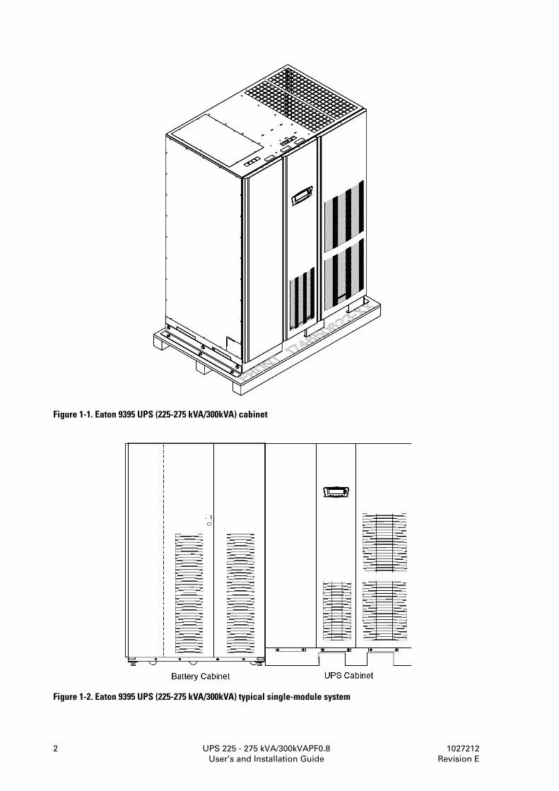
Figure 1-1. Eaton 9395 UPS (225-275 kVA/300kVA) cabinet
Figure 1-2. Eaton 9395 UPS (225-275 kVA/300kVA) typical single-module system
2 UPS 225 - 275 kVA/300kVAPF0.8 1027212User’s and Installation Guide Revision E
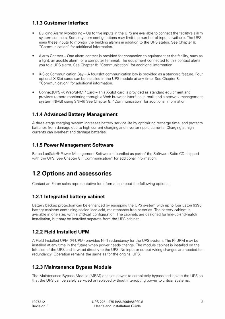
1.1.3 Customer Interface
• Building Alarm Monitoring – Up to five inputs in the UPS are available to connect the facility’s alarm system contacts. Some system configurations may limit the number of inputs available. The UPS uses these inputs to monitor the building alarms in addition to the UPS status. See Chapter 8: “Communication” for additional information.
• Alarm Contact – One alarm contact is provided for connection to equipment at the facility, such as a light, an audible alarm, or a computer terminal. The equipment connected to this contact alerts you to a UPS alarm. See Chapter 8: “Communication” for additional information.
• X-Slot Communication Bay – A four-slot communication bay is provided as a standard feature. Four optional X-Slot cards can be installed in the UPS module at any time. See Chapter 8: “Communication” for additional information.
• ConnectUPS -X Web/SNMP Card – This X-Slot card is provided as standard equipment and provides remote monitoring through a Web browser interface, e-mail, and a network management system (NMS) using SNMP. See Chapter 8: “Communication” for additional information.
1.1.4 Advanced Battery Management
A three-stage charging system increases battery service life by optimizing recharge time, and protects batteries from damage due to high current charging and inverter ripple currents. Charging at high currents can overheat and damage batteries.
1.1.5 Power Management Software
Eaton LanSafe® Power Management Software is bundled as part of the Software Suite CD shipped with the UPS. See Chapter 8: “Communication” for additional information.
1.2 Options and accessories
Contact an Eaton sales representative for information about the following options.
1.2.1 Integrated battery cabinet
Battery backup protection can be enhanced by equipping the UPS system with up to four Eaton 9395 battery cabinets containing sealed lead-acid, maintenance-free batteries. The battery cabinet is available in one size, with a 240-cell configuration. The cabinets are designed for line-up-and-match installation, but may be installed separate from the UPS cabinet.
1.2.2 Field Installed UPM
A Field Installed UPM (FI-UPM) provides N+1 redundancy for the UPS system. The FI-UPM may be installed at any time in the future when power needs change. The module cabinet is installed on the left side of the UPS and is wired directly to the UPS. No input or output wiring changes are needed for redundancy. Operation remains the same as for the original UPS.
1.2.3 Maintenance Bypass Module
The Maintenance Bypass Module (MBM) enables power to completely bypass and isolate the UPS so that the UPS can be safely serviced or replaced without interrupting power to critical systems.
1027212 UPS 225 - 275 kVA/300kVAPF0.8 3Revision E User’s and Installation Guide
1.2.4 Sync Control
An optional Eaton 9395 Sync Control maintains the critical load outputs of two separate single module Eaton 9395 UPS systems in synchronization. This option facilitates the uninterrupted transfer of the load from one load bus to another by means of a transfer switch. The Sync Control is housed in a wall-mounted panel that can be located between the UPS units for easy wiring.
1.2.5 Single-feed kit
An optional kit is available for converting the dual-feed rectifier and bypass inputs to a single-feed configuration. The kit consists of jumpers and bus bar extenders for each phase, and the hardware required for installation.
1.2.6 Distributed Bypass System
There are two types of redundancy: UPS based (based on the number of UPSs) and UPM based (based on the number of UPMs). Each UPS can contain one or two UPMs.
A distributed bypass UPS system with two to five UPS units can be installed to provide a capacity and/or redundant system. This load sharing system provides more capacity than a single UPS, and can provide redundancy, depending on the load and configuration. In addition, when one UPM or UPS is taken out of service for maintenance or is not operating properly, a redundant UPM or UPS continues to supply uninterrupted power to the critical load. An Eaton HotSync® Controller Area Network (CAN) provides connectivity and operational mode control. The distributed bypass system consists of two to five UPS units each with a CAN card (for paralleling the UPSs), and a customer-supplied tie cabinet or load distribution panel to act as a tie point.
The tie cabinet must contain Module Output Breakers (MOBs) with dual auxiliary contacts for control of the system. Without dual auxiliary MOBs, UPSs are not allowed to go to bypass individually during servicing. All UPSs will go to bypass instead of just the UPS needing service, decreasing critical load protection. With dual auxiliary MOBs, one UPS can be bypassed while the remaining UPSs support the load as long as the remaining UPMs have the capacity to do so.
1.2.7 Input Output Module configuration
The UPS can be supplied in an Input Output Module (IOM) configuration without the bypass input connections, the static switch, and the backfeed protection contactor. This configuration is primarily used in multiple UPS parallel systems that do not need a bypass for each UPS and use a separate System Bypass Module (SBM) to provide system bypass capabilities.
1.2.8 Inherent redundancy
To deliver greater reliability, the Eaton 9395 UPS can be configured by an authorized Eaton Customer Service Engineer for inherent redundancy. When configured, the UPS automatically becomes redundant if the load is at or below the capacity of the UPMs minus the capacity of one UPM. Under normal conditions the UPMs in the UPS share the load equally. If one or more UPMs becomes unavailable and the load is at or below the capacity of remaining UPMs, the remaining UPMs supply the load instead of transferring to bypass.
If the capacity of the UPMs falls below the redundancy level or the load increases above redundancy level, but is still able to maintain the load, a loss of redundancy alarm is sounded. If the load exceeds the capacity of remaining UPMs, the UPS transfers to bypass.
4 UPS 225 - 275 kVA/300kVAPF0.8 1027212User’s and Installation Guide Revision E

1.2.9 Energy Saver and High Alert modes
NOTE
The Variable Module Management System and Energy Saver System modes are mutually
exclusive.
Energy Saver mode allows the UPS to operate in Bypass mode. In this mode, the UPS is operating on bypass, with the UPMs in standby, ready to automatically transfer to Normal mode if a commercial electrical power brownout, blackout, overvoltage, undervoltage, or out-of-tolerance frequency condition occurs. In High Alert mode the unit transfers from Energy Saver mode to Normal mode (inverter online) or if in Normal mode remains in Normal mode for a default time period of one hour. The High Alert mode time period is configurable by an Eaton Customer Service Engineer. The High Alert mode allows the user to place the unit online with full protection when outside conditions could cause a power disturbance. At the end of the time period, the unit defaults back to Energy Saver mode. If the High Alert mode is reactivated during the time period, the timer will be restarted.
1.2.10 Variable Module Management System and High Alert modes
NOTE
The Variable Module Management System and Energy Saver System modes are mutually
exclusive.
The Variable Module Management System (VMMS) mode maintains UPM redundancy and achieves higher efficiencies by intelligently controlling the UPM’s load level. The efficiency rating for each UPM is highest when loads are greater than 50% of its rating. Therefore, shifting the load to fewer UPMs can achieve higher efficiencies when the UPS load is lighter.
In VMMS mode, the UPS is actively monitoring the critical bus and UPMs are available to assume load in less than 2 ms to respond to load changes.
The VMMS feature has three configurable modes of operation: Online mode, Online mode with VMMS, and High Alert mode. All modes are selectable from the front panel.
VMMS mode supports both distributed bypass and SBM parallel configurations.
In High Alert mode, all idle UPMs go online for one hour. At the end of the hour, the UPS defaults back to VMMS mode. If the High Alert mode is reactivated during the one hour, the one hour timer will be restarted.
1.2.11 Optional X-Slot cards
The optional X-Slot cards support several protocols, such as SNMP, HTTP, AS/400®, and Modbus®. See Chapter 8: “Communication” for additional information.
1.3 Basic system configurations
The following basic UPS system configurations are possible:
• Single UPS with one UPM and two to four battery cabinets for the UPM
1027212 UPS 225 - 275 kVA/300kVAPF0.8 5Revision E User’s and Installation Guide
• Single UPS with one UPM with a common battery, an FI-UPM with a common battery, and two to four battery cabinets for the UPMs
• Single UPS with one UPM with a separate battery, an FI-UPM with a separate battery, and two to three battery cabinets per UPM
• Single UPS with one UPM and a standalone battery rack system
• Single UPS with one UPM with a common battery, an FI-UPM with a common battery, and one standalone battery rack system for the UPMs
• Single UPS with one UPM with a separate battery, an FI-UPM with a separate battery, and one standalone battery rack system per UPM
• Distributed bypass system with two to five UPSs and a customer-supplied tie cabinet
The UPS system configuration can be enhanced by adding optional accessories such as a Remote Emergency Power-off (REPO) control, RMP II, or X-Slot communication cards.
1.4 Using this manual
This manual describes how to install and operate the Eaton 9395 UPS (225-275 kVA/300kVA) cabinet. Read and understand the procedures described in this manual to ensure trouble-free installation and operation. In particular, be thoroughly familiar with the REPO procedure (see Section “Using the Remote Emergency Power-off switch” on page 95).
The information in this manual is divided into sections and chapters. The system, options, and accessories being installed dictate which parts of this manual should be read. At a minimum, Chapters 1 through 4 and Chapter 7 should be examined.
Read through each procedure before beginning the procedure. Perform only those procedures that apply to the UPS system being installed or operated.
1.5 Conventions used in this manual
This manual uses these type conventions:
• Bold type highlights important concepts in discussions, key terms in procedures, and menu options, or represents a command or option that you type or enter at a prompt.
• Italic type highlights notes and new terms where they are defined.
• Screen type represents information that appears on the screen or LCD.
In this manual, the term UPS refers only to the UPS cabinet and its internal elements.The term UPS system refers to the entire power protection system – the UPS cabinet, the battery cabinet, and options or accessories installed.
Icon Description
Information notes call attention to important features or instructions.
[Keys] Brackets are used when referring to a specific key, such as [Enter] or [Ctrl].
6 UPS 225 - 275 kVA/300kVAPF0.8 1027212User’s and Installation Guide Revision E
1.6 Symbols, controls, and indicators
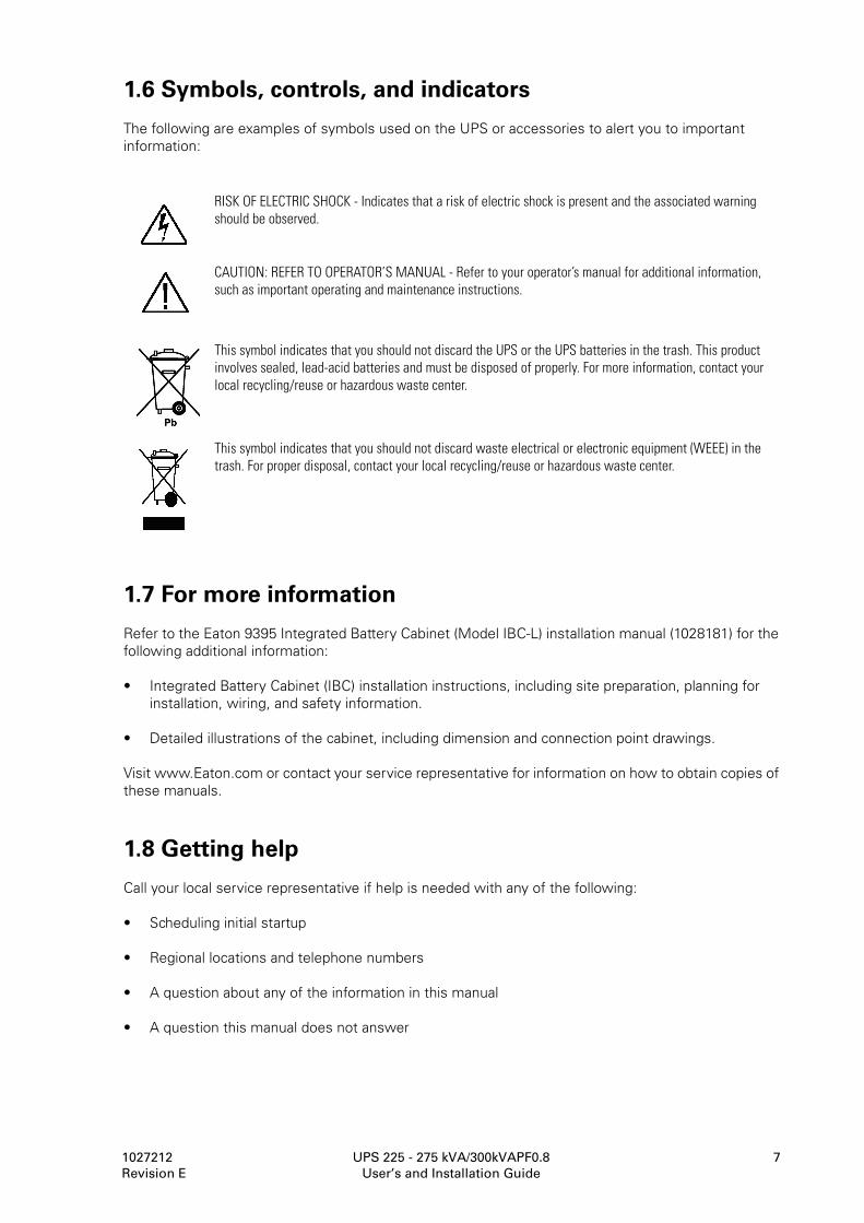
The following are examples of symbols used on the UPS or accessories to alert you to important information:
1.7 For more information
Refer to the Eaton 9395 Integrated Battery Cabinet (Model IBC-L) installation manual (1028181) for the following additional information:
• Integrated Battery Cabinet (IBC) installation instructions, including site preparation, planning for installation, wiring, and safety information.
• Detailed illustrations of the cabinet, including dimension and connection point drawings.
Visit www.Eaton.com or contact your service representative for information on how to obtain copies of these manuals.
1.8 Getting help
Call your local service representative if help is needed with any of the following:
• Scheduling initial startup
• Regional locations and telephone numbers
• A question about any of the information in this manual
• A question this manual does not answer
RISK OF ELECTRIC SHOCK - Indicates that a risk of electric shock is present and the associated warning should be observed.
CAUTION: REFER TO OPERATOR’S MANUAL - Refer to your operator’s manual for additional information, such as important operating and maintenance instructions.
This symbol indicates that you should not discard the UPS or the UPS batteries in the trash. This product involves sealed, lead-acid batteries and must be disposed of properly. For more information, contact your local recycling/reuse or hazardous waste center.
This symbol indicates that you should not discard waste electrical or electronic equipment (WEEE) in the trash. For proper disposal, contact your local recycling/reuse or hazardous waste center.
1027212 UPS 225 - 275 kVA/300kVAPF0.8 7Revision E User’s and Installation Guide
2 Safety warnings
IMPORTANT SAFETY INSTRUCTIONS
SAVE THESE INSTRUCTIONS
This manual contains important instructions that should be followed during installation and maintenance of the UPS and batteries. Please read all instructions before operating the equipment and save this manual for future reference. The UPS is designed for computer room applications, and contains safety shields behind the door and front panels. However, the UPS is a sophisticated power system and should be handled with appropriate care.
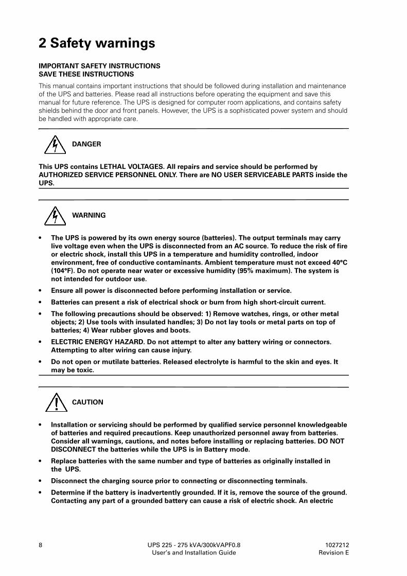
DANGER
This UPS contains LETHAL VOLTAGES. All repairs and service should be performed by
AUTHORIZED SERVICE PERSONNEL ONLY. There are NO USER SERVICEABLE PARTS inside the
UPS.
WARNING
• The UPS is powered by its own energy source (batteries). The output terminals may carry
live voltage even when the UPS is disconnected from an AC source. To reduce the risk of fire
or electric shock, install this UPS in a temperature and humidity controlled, indoor
environment, free of conductive contaminants. Ambient temperature must not exceed 40°C
(104°F). Do not operate near water or excessive humidity (95% maximum). The system is
not intended for outdoor use.
• Ensure all power is disconnected before performing installation or service.
• Batteries can present a risk of electrical shock or burn from high short-circuit current.
• The following precautions should be observed: 1) Remove watches, rings, or other metal
objects; 2) Use tools with insulated handles; 3) Do not lay tools or metal parts on top of
batteries; 4) Wear rubber gloves and boots.
• ELECTRIC ENERGY HAZARD. Do not attempt to alter any battery wiring or connectors.
Attempting to alter wiring can cause injury.
• Do not open or mutilate batteries. Released electrolyte is harmful to the skin and eyes. It
may be toxic.
CAUTION
• Installation or servicing should be performed by qualified service personnel knowledgeable
of batteries and required precautions. Keep unauthorized personnel away from batteries.
Consider all warnings, cautions, and notes before installing or replacing batteries. DO NOT
DISCONNECT the batteries while the UPS is in Battery mode.
• Replace batteries with the same number and type of batteries as originally installed in
the UPS.
• Disconnect the charging source prior to connecting or disconnecting terminals.
• Determine if the battery is inadvertently grounded. If it is, remove the source of the ground.
Contacting any part of a grounded battery can cause a risk of electric shock. An electric
8 UPS 225 - 275 kVA/300kVAPF0.8 1027212User’s and Installation Guide Revision E

shock is less likely if you disconnect the grounding connection before you work on the
batteries.
• Proper disposal of batteries is required. Refer to local codes for disposal requirements.
• Do not dispose of batteries in a fire. Batteries may explode when exposed to flame.
• Keep the UPS door closed and front panels installed to ensure proper cooling airflow and to
protect personnel from dangerous voltages inside the unit.
• Do not install or operate the UPS system close to gas or electric heat sources.
• The operating environment should be maintained within the parameters stated in this
manual.
• Keep surroundings uncluttered, clean, and free from excess moisture.
• Observe all DANGER, CAUTION, and WARNING notices affixed to the inside and outside of
the equipment.
CAUTION
To prevent damage to the wiring channel and wiring in the UPS cabinet base when lifting or
moving the cabinet:
• Lift and move the cabinet using only the front or rear forklift slots.
• Verify that the forklift forks are in a horizontal position before inserting them into the forklift
slots. DO NOT angle fork tips upward.
• Insert the forks all the way through the base. DO NOT insert forks partially into the base to
move the cabinet.
• Forks may be partially inserted into the front or rear forklift slots for minor positioning if the
forks are kept in a horizontal position with no upward angling.
• DO NOT use the forklift slots on the end of the cabinet to move the cabinet.
• End forklift slots may be used for minor positioning if the forks are kept in a horizontal
position with no upward angling.
If these instructions are not followed, damage to the wiring channel and wiring will occur.
1027212 UPS 225 - 275 kVA/300kVAPF0.8 9Revision E User’s and Installation Guide
10 UPS 225 - 275 kVA/300kVAPF0.8 1027212User’s and Installation Guide Revision E
3 UPS installation plan and unpacking
Use the following basic sequence of steps to install the UPS:
1. Create an installation plan for the UPS system (Chapter 3).2. Prepare your site for the UPS system (Chapter 3).3. Inspect and unpack the UPS cabinet (Chapter 3).4. Unload and install the UPS cabinet, and wire the system (Chapter 4: “UPS system installation”).5. Complete the installation checklist at the end of this manual.6. Have authorized service personnel perform preliminary operational checks and startup.
NOTE
Startup and operational checks must be performed by an authorized Eaton Customer Service
Engineer, or the warranty terms specified on page 124 become void. This service is offered as
part of the sales contract for the UPS. Contact service in advance (usually a two-week notice is
required) to reserve a preferred startup date.
3.1 Creating an installation plan
Before installing the UPS system, read and understand how this manual applies to the system being installed. Use the procedures and illustrations in Section 3.2 and Chapter 4: “UPS system installation” to create a logical plan for installing the system.
3.2 Preparing the site
For the UPS system to operate at peak efficiency, the installation site should meet the environmental parameters outlined in this manual. If the UPS is to be operated at an altitude higher than 1000 m, contact your service representative for important information about high altitude operation. The operating environment must meet the weight, clearance, and environmental requirements specified.
3.2.1 Environmental and installation considerations
The UPS system installation must meet the following guidelines:
• The system must be installed on a level floor suitable for computer or electronic equipment.
• The system must be installed in a temperature and humidity controlled indoor area free of conductive contaminants.
• The cabinet can be installed in line-up-and-match or standalone configurations.
Failure to follow guidelines may void your warranty.
The UPS equipment operating environment must meet the weight requirements shown in Table 3-1 and the size requirements shown in Figure 3-1 through Figure 3-7. Dimensions are in millimeters.
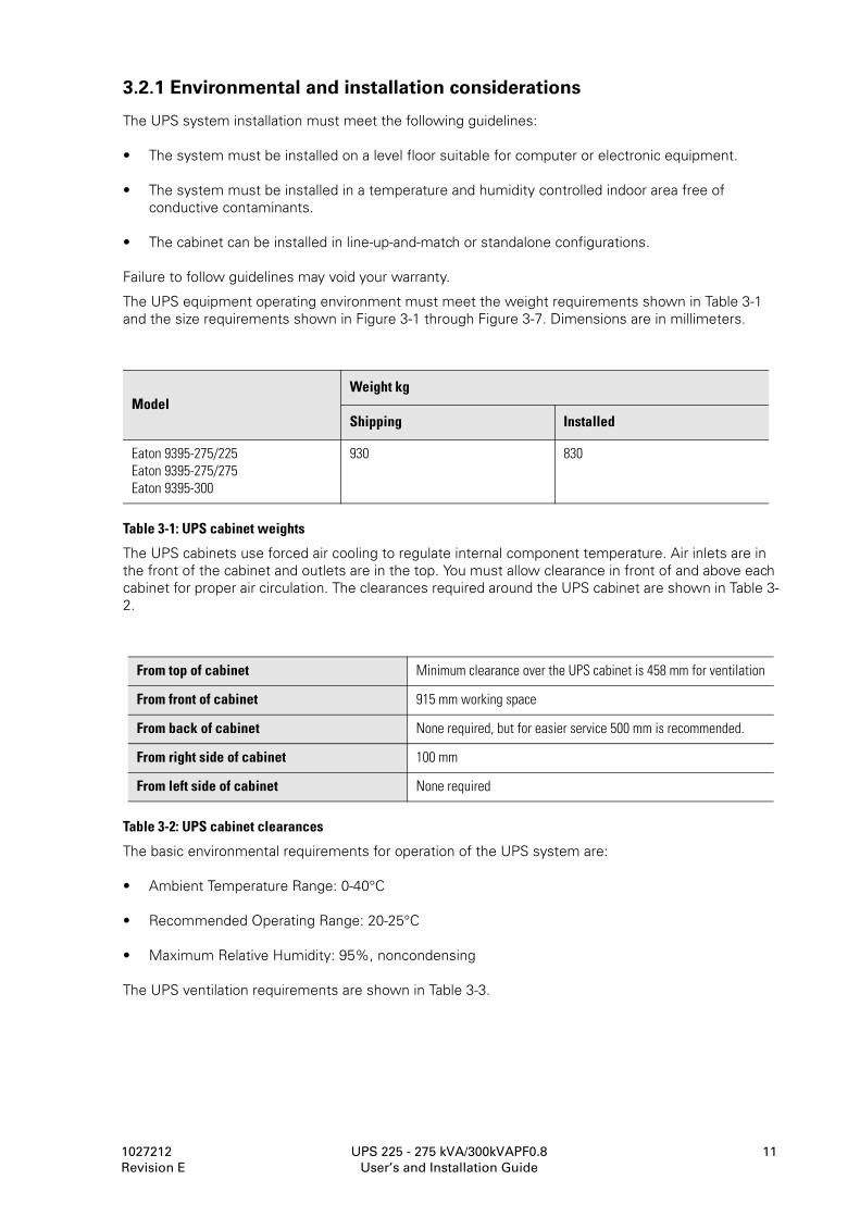
Table 3-1: UPS cabinet weights
The UPS cabinets use forced air cooling to regulate internal component temperature. Air inlets are in the front of the cabinet and outlets are in the top. You must allow clearance in front of and above each cabinet for proper air circulation. The clearances required around the UPS cabinet are shown in Table 3-2.
Table 3-2: UPS cabinet clearances
The basic environmental requirements for operation of the UPS system are:
• Ambient Temperature Range: 0-40°C
• Recommended Operating Range: 20-25°C
• Maximum Relative Humidity: 95%, noncondensing
The UPS ventilation requirements are shown in Table 3-3.
ModelWeight kg
Shipping Installed
Eaton 9395-275/225Eaton 9395-275/275Eaton 9395-300
930 830
From top of cabinet Minimum clearance over the UPS cabinet is 458 mm for ventilation
From front of cabinet 915 mm working space
From back of cabinet None required, but for easier service 500 mm is recommended.
From right side of cabinet 100 mm
From left side of cabinet None required
1027212 UPS 225 - 275 kVA/300kVAPF0.8 11Revision E User’s and Installation Guide
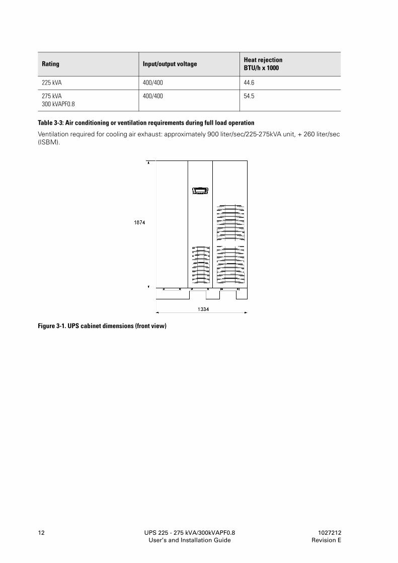
Table 3-3: Air conditioning or ventilation requirements during full load operation
Ventilation required for cooling air exhaust: approximately 900 liter/sec/225-275kVA unit, + 260 liter/sec (ISBM).
Figure 3-1. UPS cabinet dimensions (front view)
Rating Input/output voltage Heat rejectionBTU/h x 1000
225 kVA 400/400 44.6
275 kVA300 kVAPF0.8
400/400 54.5
12 UPS 225 - 275 kVA/300kVAPF0.8 1027212User’s and Installation Guide Revision E
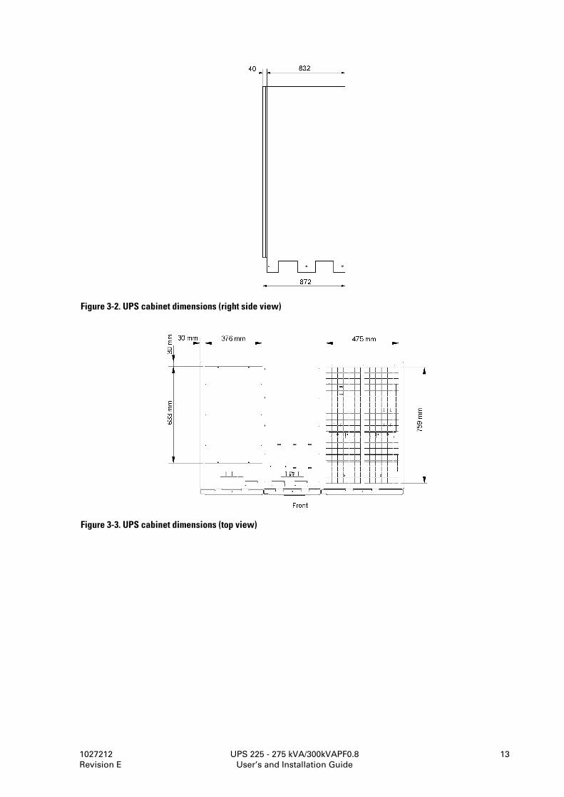
Figure 3-2. UPS cabinet dimensions (right side view)
Figure 3-3. UPS cabinet dimensions (top view)
1027212 UPS 225 - 275 kVA/300kVAPF0.8 13Revision E User’s and Installation Guide
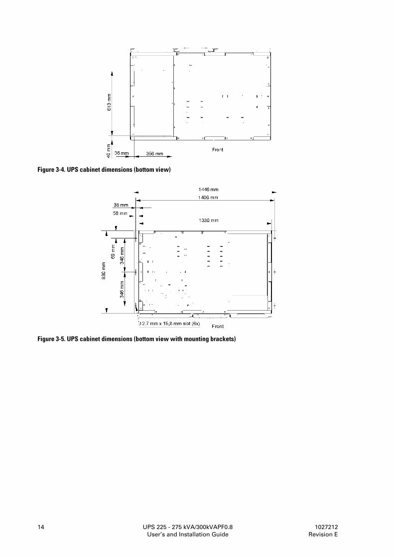
Figure 3-4. UPS cabinet dimensions (bottom view)
Figure 3-5. UPS cabinet dimensions (bottom view with mounting brackets)
14 UPS 225 - 275 kVA/300kVAPF0.8 1027212User’s and Installation Guide Revision E
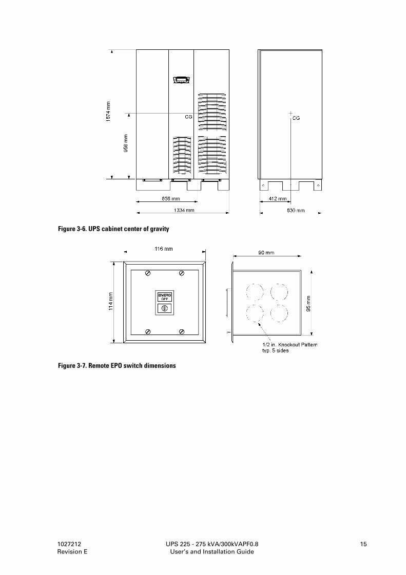
Figure 3-6. UPS cabinet center of gravity
Figure 3-7. Remote EPO switch dimensions
1027212 UPS 225 - 275 kVA/300kVAPF0.8 15Revision E User’s and Installation Guide
3.2.2 UPS system power wiring preparation
NOTE
If installing, as part of the UPS system, a maintenance bypass without a rectifier input breaker, a
minimum of two separate feeds with upstream feeder breakers, or one feed with two upstream
feeder breakers, must be provided: one for the UPS and one for the maintenance bypass input.
DO NOT use one feed or a single feeder breaker to supply both the UPS and the maintenance
bypass.
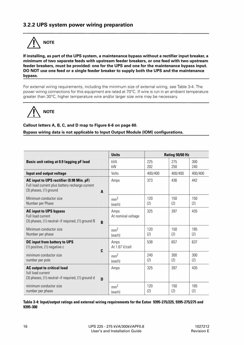
For external wiring requirements, including the minimum size of external wiring, see Table 3-4. The power wiring connections for this equipment are rated at 70°C. If wire is run in an ambient temperature greater than 30°C, higher temperature wire and/or larger size wire may be necessary.
NOTE
Callout letters A, B, C, and D map to Figure 6-6 on page 60.
Bypass wiring data is not applicable to Input Output Module (IOM) configurations.
Table 3-4: Input/output ratings and external wiring requirements for the Eaton 9395-275/225, 9395-275/275 and 9395-300
Units Rating 50/60 Hz
Basic unit rating at 0.9 lagging pF load kVAkW
225202
275250
300240
Input and output voltage Volts 400/400 400/400 400/400
AC input to UPS rectifier (0.98 Min. pF)Full load current plus battery recharge current(3) phases, (1) ground A
Amps 373 436 442
Minimum conductor sizeNumber per Phase
mm2 (each)
120(2)
150(2)
150(2)
AC input to UPS bypassFull load current(3) phases, (1) neutral–if required, (1) ground B B
AmpsAt nominal voltage
325 397 435
Minimum conductor sizeNumber per phase
mm2 (each)
120(2)
150(2)
185(2)
DC input from battery to UPS(1) positive, (1) negative c
C
AmpsAt 1.67 V/cell
538 657 637
minimum conductor sizenumber per pole
mm2 (each)
240(2)
300(2)
300(2)
AC output to critical loadfull load current(3) phases, (1) neutral–if required, (1) ground d D
Amps 325 397 435
minimum conductor sizenumber per phase
mm2 (each)
120(2)
150(2)
185(2)
16 UPS 225 - 275 kVA/300kVAPF0.8 1027212User’s and Installation Guide Revision E

Read and understand the following notes while planning and performing the installation:
• Refer to national and local electrical codes for acceptable external wiring practices.
• Material and labor for external wiring requirements are to be provided by designated personnel.
• For external wiring, use 70°C copper wire. See the appropriate information in Table 3-4. Wire sizes are based on using the specified breakers.
• The bypass feed into this equipment uses three or four wires. The rectifier feed into this equipment uses three wires. The phases must be symmetrical about ground (from a Wye source) for proper equipment operation.
• If the load requires a neutral, a bypass source neutral must be provided. If the load does not require a neutral and there is no neutral conductor connected at the bypass input, an optional neutral forming kit must be used.
• The UPS cabinet is shipped with a debris shield covering the ventilation grill on top of the unit. Do not remove the debris shield until installation is complete. However, remove the shield before operating the UPS. Once the debris shield is removed, do not place objects on the ventilation grill.
Terminals E1 through E12 are 2-hole bus bar mountings. See Table 3-5 for power cable terminations and Table 3-6 for recommended installation parts not supplied by Eaton Corporation. Figure 4-5 on page 31 and Figure 4-6 on page 31 show the location of the power cable terminals inside the UPS.
Table 3-5: UPS cabinet power cable terminations for the Eaton 9395-275/225, 9395-275/275 and 9395-300
NOTE
Bypass terminations are not applicable to IOM configurations.
Terminal function Terminal Function Bus landing Tightening torque Nm Bolt size
AC input to UPS rectifier E1 Phase L1 4-2 bolt mounting 76 M12
E2 Phase L2 4-2 bolt mounting 76 M12
E3 Phase L3 4-2 bolt mounting 76 M12
AC input to bypass E6 Phase L1 4-2 bolt mounting 76 M12
E7 Phase L2 4-2 bolt mounting 76 M12
E8 Phase L3 4-2 bolt mounting 76 M12
AC output to critical load E9 Phase L1 4-2 bolt mounting 76 M12
E10 Phase L2 4-2 bolt mounting 76 M12
E11 Phase L3 4-2 bolt mounting 76 M12
DC input from battery to UPS E4 Battery (+) 4-2 bolt mounting 76 M12
E5 Battery (-) 4-2 bolt mounting 76 M12
Input and output neutral E12 Neutral 8-2 bolt mounting 22 M10
Customer ground Ground Ground 7-1 bolt mounting 22 M10
1027212 UPS 225 - 275 kVA/300kVAPF0.8 17Revision E User’s and Installation Guide
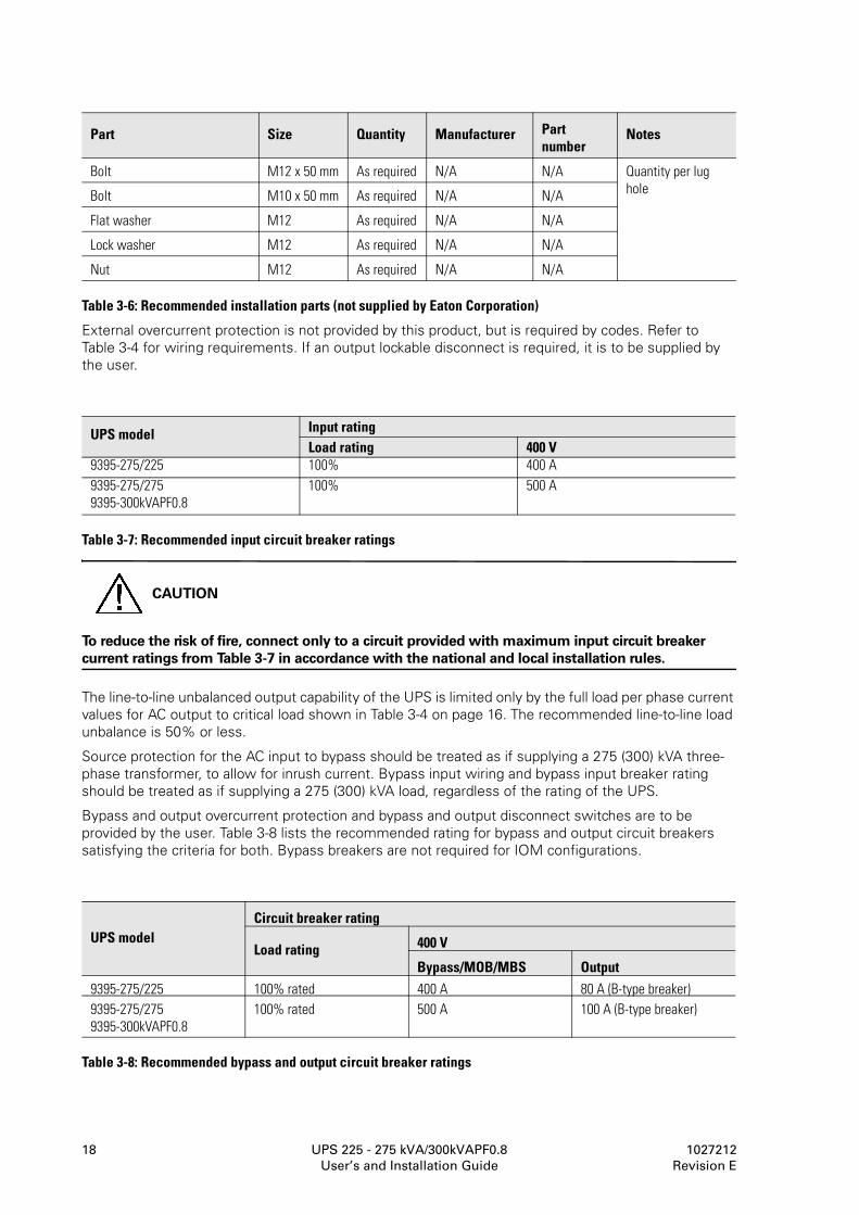
Table 3-6: Recommended installation parts (not supplied by Eaton Corporation)
External overcurrent protection is not provided by this product, but is required by codes. Refer to Table 3-4 for wiring requirements. If an output lockable disconnect is required, it is to be supplied by the user.
Table 3-7: Recommended input circuit breaker ratings
CAUTION
To reduce the risk of fire, connect only to a circuit provided with maximum input circuit breaker
current ratings from Table 3-7 in accordance with the national and local installation rules.
The line-to-line unbalanced output capability of the UPS is limited only by the full load per phase current values for AC output to critical load shown in Table 3-4 on page 16. The recommended line-to-line load unbalance is 50% or less.
Source protection for the AC input to bypass should be treated as if supplying a 275 (300) kVA three-phase transformer, to allow for inrush current. Bypass input wiring and bypass input breaker rating should be treated as if supplying a 275 (300) kVA load, regardless of the rating of the UPS.
Bypass and output overcurrent protection and bypass and output disconnect switches are to be provided by the user. Table 3-8 lists the recommended rating for bypass and output circuit breakers satisfying the criteria for both. Bypass breakers are not required for IOM configurations.
Table 3-8: Recommended bypass and output circuit breaker ratings
Part Size Quantity Manufacturer Part number
Notes
Bolt M12 x 50 mm As required N/A N/A Quantity per lug holeBolt M10 x 50 mm As required N/A N/A
Flat washer M12 As required N/A N/A
Lock washer M12 As required N/A N/A
Nut M12 As required N/A N/A
UPS model Input ratingLoad rating 400 V
9395-275/225 100% 400 A9395-275/2759395-300kVAPF0.8
100% 500 A
UPS modelCircuit breaker rating
Load rating 400 V
Bypass/MOB/MBS Output9395-275/225 100% rated 400 A 80 A (B-type breaker)9395-275/2759395-300kVAPF0.8
100% rated 500 A 100 A (B-type breaker)
18 UPS 225 - 275 kVA/300kVAPF0.8 1027212User’s and Installation Guide Revision E
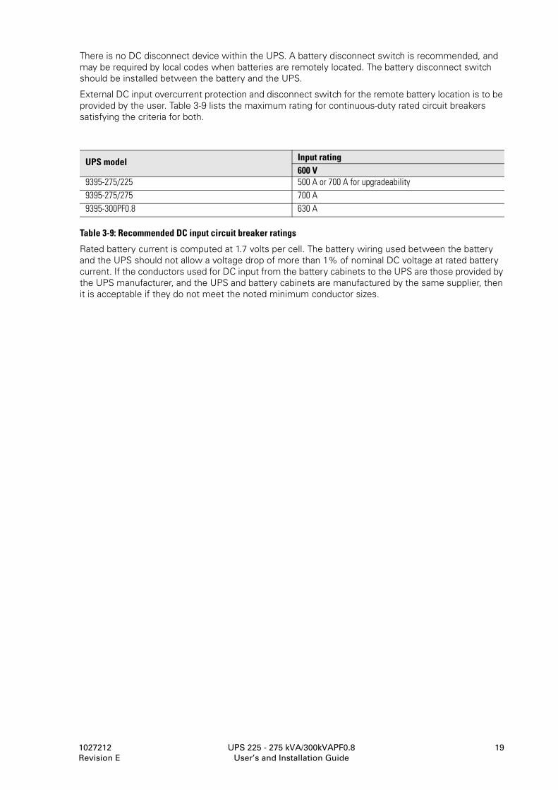
There is no DC disconnect device within the UPS. A battery disconnect switch is recommended, and may be required by local codes when batteries are remotely located. The battery disconnect switch should be installed between the battery and the UPS.
External DC input overcurrent protection and disconnect switch for the remote battery location is to be provided by the user. Table 3-9 lists the maximum rating for continuous-duty rated circuit breakers satisfying the criteria for both.
Table 3-9: Recommended DC input circuit breaker ratings
Rated battery current is computed at 1.7 volts per cell. The battery wiring used between the battery and the UPS should not allow a voltage drop of more than 1% of nominal DC voltage at rated battery current. If the conductors used for DC input from the battery cabinets to the UPS are those provided by the UPS manufacturer, and the UPS and battery cabinets are manufactured by the same supplier, then it is acceptable if they do not meet the noted minimum conductor sizes.
UPS model Input rating600 V
9395-275/225 500 A or 700 A for upgradeability9395-275/275 700 A9395-300PF0.8 630 A
1027212 UPS 225 - 275 kVA/300kVAPF0.8 19Revision E User’s and Installation Guide
20 UPS 225 - 275 kVA/300kVAPF0.8 1027212User’s and Installation Guide Revision E
3.2.3 UPS system interface wiring preparation
Control wiring for features and options should be connected at the customer interface terminal blocks located inside the UPS as described in Chapter 5: “Installing options and accessories”.
WARNING
Do not directly connect relay contacts to the mains related circuits. Reinforced insulation to the
mains is required.
Read and understand the following notes while planning and performing the installation:
• Install the interface wiring (for example, building alarm, relay output, battery breaker trip, and X-Slot) separate from the power wiring. The wiring should have double insulation and rated at Uo/U = 300/500 Volts.
• All interface wiring is to be provided by the customer.
• When installing internal interface wiring to X-Slot terminals, route the wiring through the internal opening in the X-Slot communication bay.
• All building alarm inputs or remote features require an isolated normally-open contact or switch (rated at 24 Vdc, 20 mA minimum) connected between the alarm input and common terminal. All control wiring and relay and switch contacts are customer-supplied. Use twisted-pair wires for each alarm input and common.
• The building alarms can be programmed to display the alarm functional name.
• LAN and telephone drops for use with X-Slot cards must be provided by facility planners or the customer.
• The UPS Battery Aux and 48 Vdc Shunt Trip signal wiring from the UPS must be connected to the DC source disconnect device.
• Battery Aux and 48 Vdc Shunt Trip wiring should be a minimum of 1.5 mm2.
• The Remote EPO feature opens all contactors in the UPS cabinet and isolates power from your critical load. Local electrical codes may also require tripping upstream protective devices to the UPS.
• The Remote EPO switch must be a dedicated switch not tied to any other circuits.
• A jumper wire must be connected between pins 1 and 2 on TB1, if the normally-closed Remote EPO contact is not used.
• Remote EPO wiring should be a minimum of 0.75 mm2 and a maximum of 2.5 mm2.
• The maximum distance between the Remote EPO and the UPS cannot exceed 150 meters.
• Alarm relay contacts have a maximum current rating of 5A and a switched voltage rating of 30 Vac and 28 Vdc.
• Alarm relay wiring should be a minimum of 0.75 mm2.
1027212 UPS 225 - 275 kVA/300kVAPF0.8 21Revision E User’s and Installation Guide
3.2.4 Distributed bypass power wiring preparation
Read and understand the following notes while planning and performing the installation:
• All distributed bypass UPS rectifier inputs must come from one source and all bypass input feeds must come from one source.
• Distributed bypass UPS input wiring size requirements and output wiring size requirements from the UPSs to the tie cabinet or distribution panel are the same as listed in Table 3-4 on page 16.
• The UPS can be installed in a high-resistance ground application only by using a factory-installed neutral forming kit.
• MOBs with dual auxiliary contacts are to be provided by the customer. Table 3-8 on page 18 lists the recommended rating for the MOBs.
The tie cabinet must contain Module Output Breakers (MOBs) with dual auxiliary contacts for control of the system. Without dual auxiliary MOBs, UPSs are not allowed to go to bypass individually during servicing. All UPSs will go to bypass instead of the just the UPS needing service, decreasing critical load protection. With dual auxiliary MOBs, one UPS can be bypassed while the remaining UPSs support the load as long as the remaining UPMs have the capacity to do so.
3.3 Inspecting and unpacking the UPS cabinet
The UPS cabinet is palleted separately for shipping. The cabinet is shipped bolted to a wooden pallet and protected with outer protective packaging material (see Figure 3-8).
WARNING
The UPS cabinet is heavy (see Table 3-1 on page 11). If unpacking instructions are not closely
followed, the cabinet may tip and cause serious injury and equipment damage.
Do not install a damaged cabinet. Report any damage to the carrier and contact your service
representative immediately.
1. Carefully inspect the outer packaging for evidence of damage during transit.
NOTE
For the following step, verify that the forklift or pallet jack is rated to handle the weight of the
cabinet (see Table 3-1 on page 11 for cabinet weight).
2. Use a forklift or pallet jack to move the packaged cabinet to the installation site, or as close as possible, before unpacking. Insert the forklift or pallet jack forks from the right side of the cabinet, between the supports on the bottom of the pallet (see Figure 3-6 on page 15 for the location of the UPS center of gravity).
WARNING
Do not tilt the UPS cabinet more than 10° from vertical or the cabinet may tip over.
3. Set the pallet on a firm, level surface, allowing a minimum clearance of 3 m on each side for removing the cabinet from the pallet.
NOTE
The UPS cabinet is shipped with a debris shield covering the ventilation grill on top of the unit.
Do not remove the debris shield until installation is complete.
4. Remove the protective covering from the cabinet.5. Remove the packing material, and discard or recycle in a responsible manner.6. After removing the protective covering, inspect the contents for any evidence of physical damage,
and compare each item with the Bill of Lading. If damage has occurred or shortages are evident, contact your service representative immediately to determine the extent of the damage and its impact upon further installation.
22 UPS 225 - 275 kVA/300kVAPF0.8 1027212User’s and Installation Guide Revision E

NOTE
While waiting for installation, protect the unpacked cabinet from moisture, dust, and other
harmful contaminants. Failure to store and protect the UPS properly may void your warranty.
Figure 3-8. Eaton 9395 UPS (225-275 kVA/300kVA) cabinet as shipped on pallet
1027212 UPS 225 - 275 kVA/300kVAPF0.8 23Revision E User’s and Installation Guide
4 UPS system installation
4.1 Preliminary installation information
WARNING
Installation should be performed only by qualified personnel.
Refer to the following while installing the UPS system:
• Chapter 3: “UPS installation plan and unpacking” for cabinet dimensions, equipment weight, wiring and terminal data, and installation notes.
• Do not tilt the cabinet more than ±10° during installation.
• The landing plates can be removed to add cable entry holes as required. Plate material is 16 gauge steel (1.5 mm/0.06” thick).
• If perforated floor tiles are required for ventilation, place them in front of the UPS.
4.2 Unloading the UPS cabinet from the pallet and
mechanical installation
The UPS cabinet is bolted to a wooden pallet supported by wood skids. To remove the pallet and mechanically install the UPS, perform the following procedure:
WARNING
The UPS cabinet is heavy. See Table 3-1 on page 11 for weight of cabinets. If unloading
instructions are not closely followed, the cabinet may cause serious injury and equipment
damage.
Do not tilt cabinets more than 10° from vertical.
Lift the cabinet only with a forklift or damage may occur.
CAUTION
To prevent damage to the wiring channel and wiring in the UPM section base when lifting or
moving the cabinet:
• Lift and move the UPS cabinet using only the front or rear fork lift slots.
• Verify that the fork lift forks are in a horizontal position before inserting them into the fork
lift slots. DO NOT angle fork slots upward.
24 UPS 225 - 275 kVA/300kVAPF0.8 1027212User’s and Installation Guide Revision E
• Insert the forks all the way through the base. DO NOT insert forks partially into the base to
move the cabinet.
• Fork may be partially inserted into the front or rear fork lift slots for minor positioning if the
forks are kept in a horizontal position with no upward angling.
• DO NOT use the forklift slots on the end of the cabinet to move the cabinet.
If these instructions are not followed, damage to the wiring channel and wiring will occur.
NOTE
For the following steps, verify that the forklift or pallet jack is rated to handle the weight of the
cabinet (see Table 3-1 on page 11 for cabinet weight).
1. If not already accomplished, use a forklift or pallet jack to move the cabinet to the installation area,or as close as possible, before unloading from the pallet. Insert the forklift or pallet jack forks fromthe right side of the cabinet, between the supports on the bottom of the pallet (see Figure 3-6 onpage 15 for the location of the UPS cabinet center of gravity).
2. Remove the three bolts securing the left side shipping bracket to the cabinet and three bolts securing the bracket to the pallet (see Figure 4-1). Remove the left shipping bracket. If permanently mounting the cabinet, retain the shipping bracket and securing hardware for later use.
3. Remove the three bolts securing the right side shipping bracket to the cabinet and three bolts securing the bracket to the pallet (see Figure 4-2). Remove the right shipping bracket. If permanently mounting the cabinet, retain the shipping bracket and securing hardware for later use.
4. Using the forklift, raise the UPS cabinet section until the cabinet bottom clears the pallet by approximately 3 mm.
5. Once the UPS cabinet is clear of the pallet, pull the pallet from under the UPS cabinet. Discard or recycle the pallet in a responsible manner.
6. Using the forklift, move the UPS cabinet to the final installation location.7. Carefully lower the UPS cabinet until the cabinet base contacts the floor.8. If permanently mounting the system, proceed to the next step; otherwise, continue to Step 11.9. Using the retained hardware, reinstall the shipping brackets removed in Steps 2 and 3 to the left
and right side of the UPS cabinet with the angle facing outward (see Figure 4-1 and Figure 4-2). 10. Secure the cabinet to the floor with customer-supplied hardware.11. If installing a field-installed UPM (FI-UPM), proceed to Section 4.3; otherwise, proceed to Step 12.12. If installing a battery system, proceed to Section 4.4; otherwise, proceed to Step 13.13. If installing a tie cabinet or distribution panel for a distributed bypass system, proceed to Section
4.5; otherwise, proceed to Section 4.6.
1027212 UPS 225 - 275 kVA/300kVAPF0.8 25Revision E User’s and Installation Guide
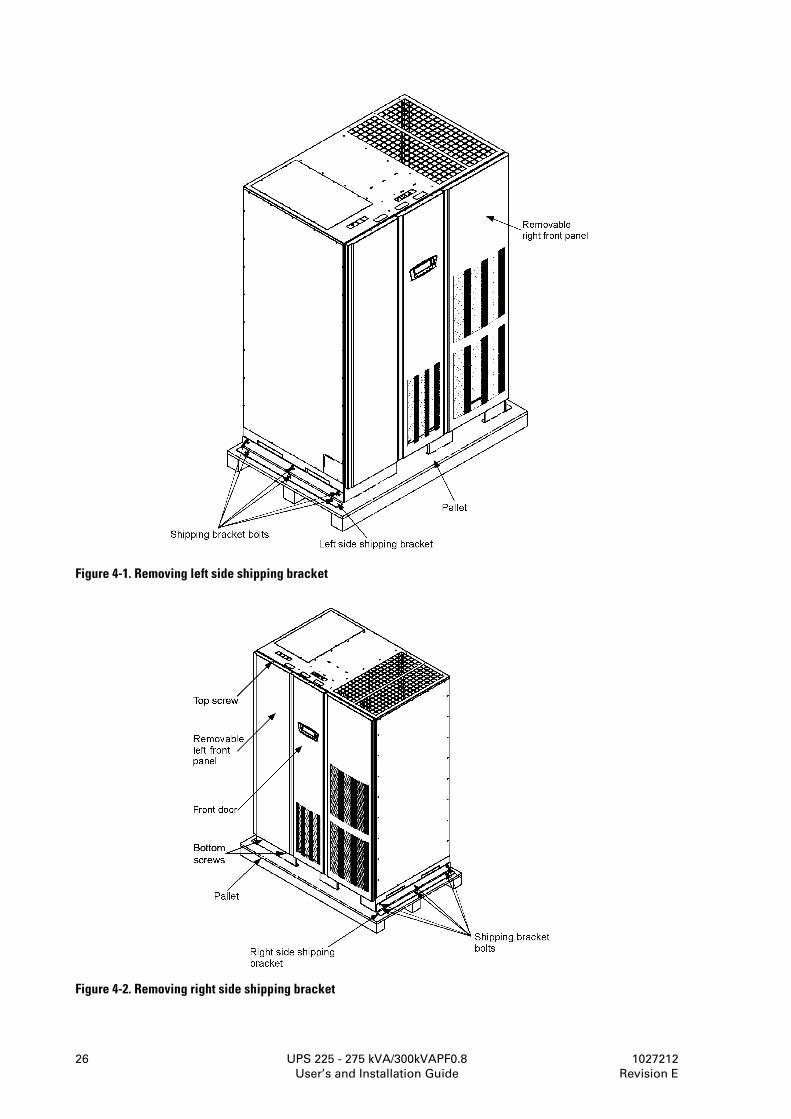
Figure 4-1. Removing left side shipping bracket
Figure 4-2. Removing right side shipping bracket
26 UPS 225 - 275 kVA/300kVAPF0.8 1027212User’s and Installation Guide Revision E
4.3 Field installed UPM (FI-UPM) installation
If installing a system with Field Upgrade UPM, install the FI-UPM using the instructions in the Eaton 9395 Field Installed UPM Mechanical Installation Manual, listed in section 1.8 on page 10. After the FI-UPM is installed, proceed to Section 4.4 if installing a battery system; otherwise, proceed to Section 4.5.
4.4 Battery cabinet installation
To install the battery cabinet, refer to the Eaton 9395 Integrated Battery Cabinet (Model IBC-L) installation manual. If installing a customer-supplied battery system, install the battery system according to the battery and battery system manufacturer’s instructions and all applicable codes and regulations.
After the battery system is installed, proceed to Section 4.5 if installing a distributed bypass tie cabinet; otherwise, proceed to Section 4.6 to complete the wiring of the UPS and battery cabinet.
4.5 Distributed bypass tie cabinet installation
NOTE
The tie cabinet must contain Module Output Breakers (MOBs) with dual auxiliary contacts for
control of the system. Without dual auxiliary MOBs, UPSs are not allowed to go to bypass
individually during servicing. All UPSs will go to bypass instead of just the UPS needing service,
decreasing critical load protection. With dual auxiliary MOBs, one UPS can be bypassed while
the remaining UPSs support the load as long as the remaining UPMs have the capacity to do so.
If installing a distributed bypass system, install the customer-supplied tie cabinet or distribution panel according to the tie cabinet or distribution panel manufacturer’s instructions and all applicable codes and regulations. After the tie cabinet is installed, proceed to Section 4.6 to complete the wiring of the UPS.
1027212 UPS 225 - 275 kVA/300kVAPF0.8 27Revision E User’s and Installation Guide
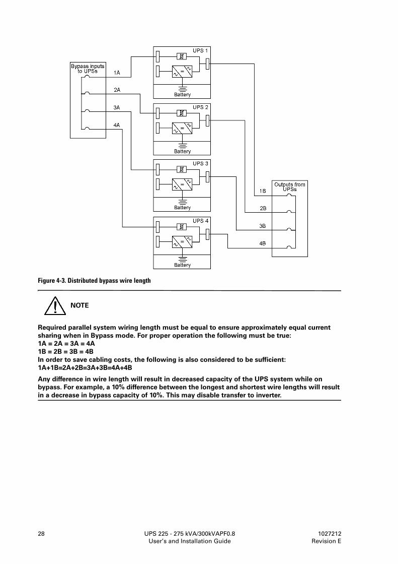
Figure 4-3. Distributed bypass wire length
NOTE
Required parallel system wiring length must be equal to ensure approximately equal current
sharing when in Bypass mode. For proper operation the following must be true:
1A = 2A = 3A = 4A
1B = 2B = 3B = 4B
In order to save cabling costs, the following is also considered to be sufficient:
1A+1B=2A+2B=3A+3B=4A+4B
Any difference in wire length will result in decreased capacity of the UPS system while on
bypass. For example, a 10% difference between the longest and shortest wire lengths will result
in a decrease in bypass capacity of 10%. This may disable transfer to inverter.
28 UPS 225 - 275 kVA/300kVAPF0.8 1027212User’s and Installation Guide Revision E
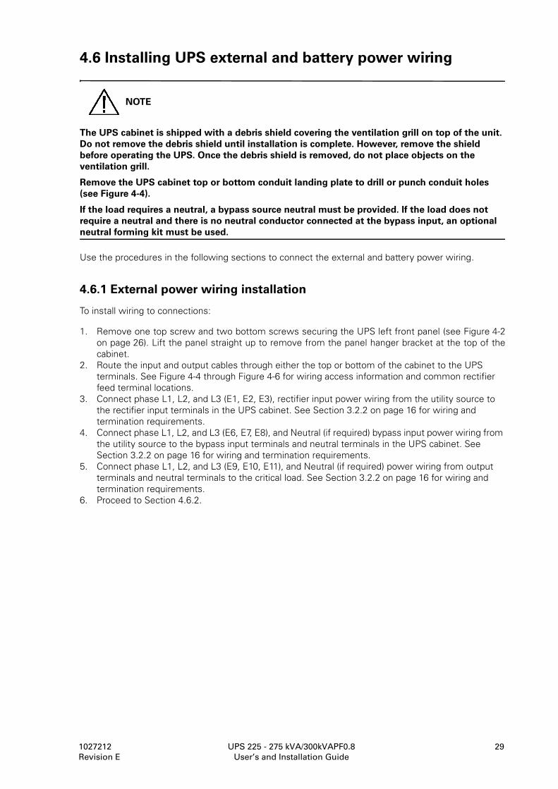
4.6 Installing UPS external and battery power wiring
NOTE
The UPS cabinet is shipped with a debris shield covering the ventilation grill on top of the unit.
Do not remove the debris shield until installation is complete. However, remove the shield
before operating the UPS. Once the debris shield is removed, do not place objects on the
ventilation grill.
Remove the UPS cabinet top or bottom conduit landing plate to drill or punch conduit holes
(see Figure 4-4).
If the load requires a neutral, a bypass source neutral must be provided. If the load does not
require a neutral and there is no neutral conductor connected at the bypass input, an optional
neutral forming kit must be used.
Use the procedures in the following sections to connect the external and battery power wiring.
4.6.1 External power wiring installation
To install wiring to connections:
1. Remove one top screw and two bottom screws securing the UPS left front panel (see Figure 4-2on page 26). Lift the panel straight up to remove from the panel hanger bracket at the top of thecabinet.
2. Route the input and output cables through either the top or bottom of the cabinet to the UPS terminals. See Figure 4-4 through Figure 4-6 for wiring access information and common rectifier feed terminal locations.
3. Connect phase L1, L2, and L3 (E1, E2, E3), rectifier input power wiring from the utility source to the rectifier input terminals in the UPS cabinet. See Section 3.2.2 on page 16 for wiring and termination requirements.
4. Connect phase L1, L2, and L3 (E6, E7, E8), and Neutral (if required) bypass input power wiring from the utility source to the bypass input terminals and neutral terminals in the UPS cabinet. See Section 3.2.2 on page 16 for wiring and termination requirements.
5. Connect phase L1, L2, and L3 (E9, E10, E11), and Neutral (if required) power wiring from output terminals and neutral terminals to the critical load. See Section 3.2.2 on page 16 for wiring and termination requirements.
6. Proceed to Section 4.6.2.
1027212 UPS 225 - 275 kVA/300kVAPF0.8 29Revision E User’s and Installation Guide
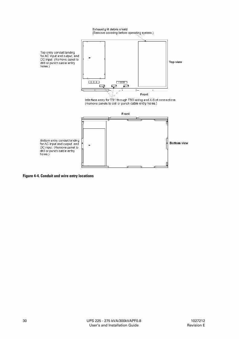
Figure 4-4. Conduit and wire entry locations
30 UPS 225 - 275 kVA/300kVAPF0.8 1027212User’s and Installation Guide Revision E
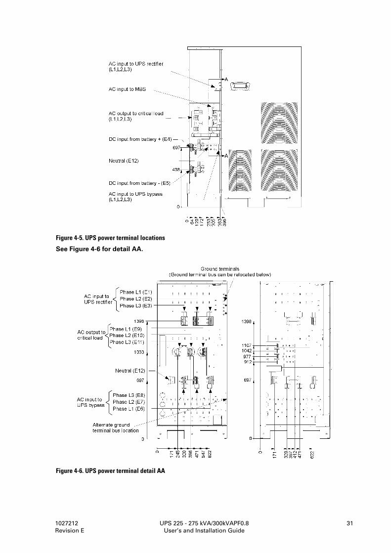
Figure 4-5. UPS power terminal locations
See Figure 4-6 for detail AA.
Figure 4-6. UPS power terminal detail AA
1027212 UPS 225 - 275 kVA/300kVAPF0.8 31Revision E User’s and Installation Guide
4.6.2 Battery wiring
CAUTION
When sizing the battery system, do not exceed the internal battery charger capabilities. See
Chapter 10: “Product specifications” for maximum battery charger current.
To install wiring to connections:
1. If using an Eaton battery cabinet, proceed to Step 2; otherwise, proceed to Step 5.2. Route and connect the battery cables between the UPS and the battery cabinets in accordance
with the instructions in the Eaton 9395 Integrated Battery Cabinet (Model IBC-L) installation manual. See Figure 4-4 through Figure 4-6 for wiring access information and terminal locations.
3. Connect the positive, negative, and ground DC power wiring from the battery cabinet to the UPS cabinet battery and ground terminals. See Section 3.2.2 on page 16 for wiring and termination requirements.
4. Proceed to Step 7.5. Route and connect the battery cables between the UPS and the battery system. See Figure 4-4
through Figure 4-6 for wiring access information and terminal locations.6. Connect the positive, negative, and ground DC power wiring from the battery system to the UPS
cabinet battery and ground terminals. See Section 3.2.2 on page 16 for wiring and termination requirements.
7. After wiring the UPS system to the facility power and critical load, be sure to ground the system according to local and/or national electrical wiring codes.
8. If wiring interface connections, proceed to Section 4.7; otherwise, proceed to Step 9.9. When all wiring is complete, reinstall the left front panel removed in Section 4.6.1 and secure with
the retained hardware.
32 UPS 225 - 275 kVA/300kVAPF0.8 1027212User’s and Installation Guide Revision E
4.7 Installing interface connections
WARNING
Hazardous voltages are present near the user interface terminal area if the UPS is not totally
disconnected.
4.7.1 TB1, TB2, and TB3 connections (other than TB1 battery interface
connections)
NOTE
Interface wiring must be installed from the top of the UPS cabinet.
To install wiring to connections:
1. Verify the UPS system is turned off and all power sources are disconnected. See Chapter 7: “UPSoperating instructions” for shutdown instructions.
2. Unfasten the front door latch and swing the door open (see Figure 4-2 on page 26).3. Remove the door. Remove the retaining screw located inside the door at the bottom hinge pivot
point, then lift the door off. Retain the hardware for later use.4. If installing interface wiring through the left interface entry conduit landing, proceed to Step 5;
otherwise, proceed to Step 7.5. If not already accomplished, remove one top screw and two bottom screws securing the UPS left
front panel (see Figure 4-2 on page 26). Lift the panel straight up to remove it from the panel hanger bracket at the top of the cabinet.
6. Remove the screws securing the protective cover panel and remove the panel. Retain the hardware for later use.
7. Terminal block TB3 is accessible on the left side of the X-Slot communication bay. To gain access to terminal blocks TB1 and TB2 and the interface entry plates, loosen the screws securing the protective cover panel and remove the panel. This panel is to the right of the X-Slot Communication Bay (see Figure 4-8 on page 35).
8. Remove the UPS cabinet top interface entry plates to drill or punch holes (see Figure 4-4 on page 30).
9. Reinstall the entry plates.
WARNING
Do not directly connect relay contacts to the mains related circuits. Reinforced insulation to the
mains is required.
10. To locate the appropriate terminals and review the wiring and termination requirements, see Section 3.2.3 on page 20, Table 4-1 on page 38, and Figure 4-7 through Figure 4-10.
11. Route and connect the wiring.12. If wiring TB1 battery interface connections, proceed to Section 4.7.2; if wiring the X-Slot
connections only, proceed to Section 4.7.3; otherwise, proceed to Step 10.13. When all wiring is complete, reinstall the protective cover panel and secure with the cabinet
mounted screws.14. Reinstall the front door and secure with the retained hardware.
1027212 UPS 225 - 275 kVA/300kVAPF0.8 33Revision E User’s and Installation Guide
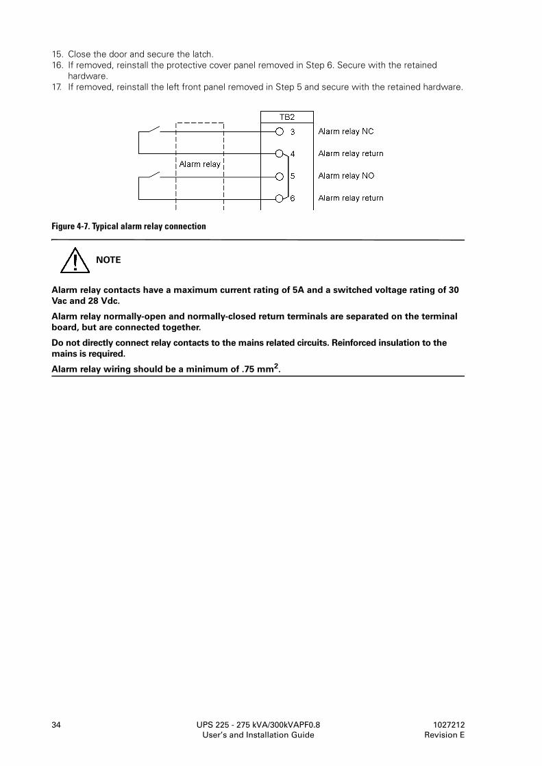
15. Close the door and secure the latch.16. If removed, reinstall the protective cover panel removed in Step 6. Secure with the retained
hardware.17. If removed, reinstall the left front panel removed in Step 5 and secure with the retained hardware.
Figure 4-7. Typical alarm relay connection
NOTE
Alarm relay contacts have a maximum current rating of 5A and a switched voltage rating of 30
Vac and 28 Vdc.
Alarm relay normally-open and normally-closed return terminals are separated on the terminal
board, but are connected together.
Do not directly connect relay contacts to the mains related circuits. Reinforced insulation to the
mains is required.
Alarm relay wiring should be a minimum of .75 mm2.
34 UPS 225 - 275 kVA/300kVAPF0.8 1027212User’s and Installation Guide Revision E
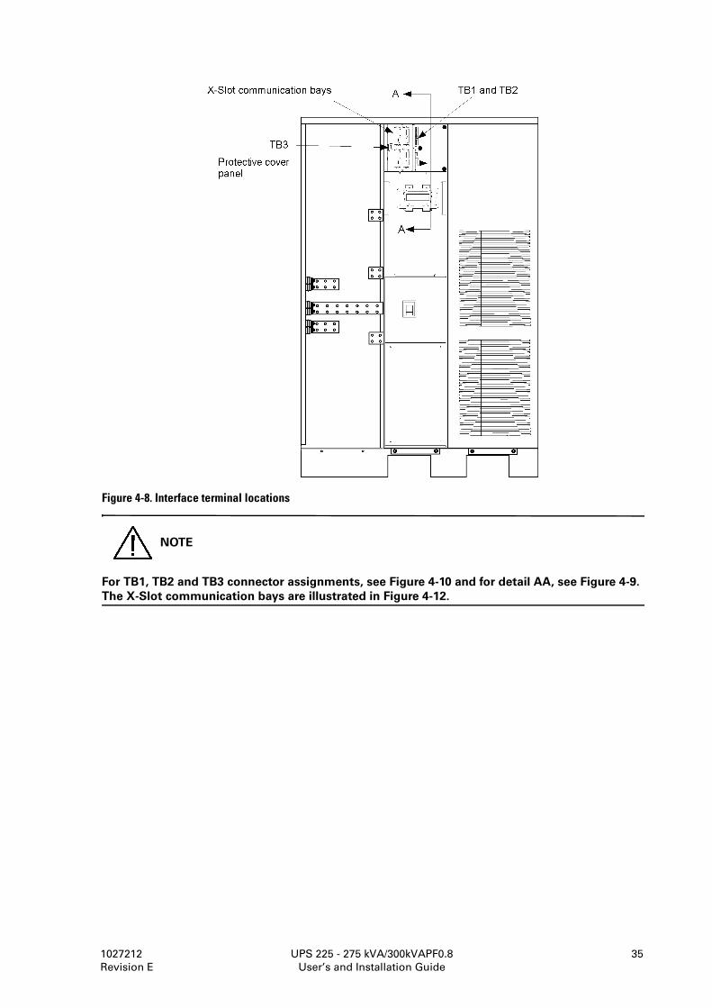
Figure 4-8. Interface terminal locations
NOTE
For TB1, TB2 and TB3 connector assignments, see Figure 4-10 and for detail AA, see Figure 4-9.
The X-Slot communication bays are illustrated in Figure 4-12.
1027212 UPS 225 - 275 kVA/300kVAPF0.8 35Revision E User’s and Installation Guide
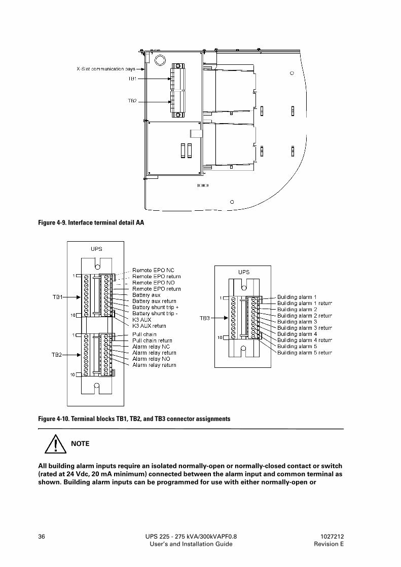
Figure 4-9. Interface terminal detail AA
Figure 4-10. Terminal blocks TB1, TB2, and TB3 connector assignments
NOTE
All building alarm inputs require an isolated normally-open or normally-closed contact or switch
(rated at 24 Vdc, 20 mA minimum) connected between the alarm input and common terminal as
shown. Building alarm inputs can be programmed for use with either normally-open or
36 UPS 225 - 275 kVA/300kVAPF0.8 1027212User’s and Installation Guide Revision E
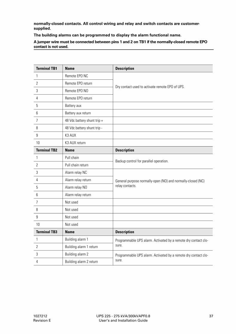
normally-closed contacts. All control wiring and relay and switch contacts are customer-
supplied.
The building alarms can be programmed to display the alarm functional name.
A jumper wire must be connected between pins 1 and 2 on TB1 if the normally-closed remote EPO
contact is not used.
Terminal TB1 Name Description
1 Remote EPO NC
Dry contact used to activate remote EPO of UPS.2 Remote EPO return
3 Remote EPO NO
4 Remote EPO return
5 Battery aux
6 Battery aux return
7 48 Vdc battery shunt trip +
8 48 Vdc battery shunt trip -
9 K3 AUX
10 K3 AUX return
Terminal TB2 Name Description
1 Pull chainBackup control for parallel operation.
2 Pull chain return
3 Alarm relay NC
General purpose normally-open (NO) and normally-closed (NC) relay contacts.
4 Alarm relay return
5 Alarm relay NO
6 Alarm relay return
7 Not used
8 Not used
9 Not used
10 Not used
Terminal TB3 Name Description
1 Building alarm 1 Programmable UPS alarm. Activated by a remote dry contact clo-sure.2 Building alarm 1 return
3 Building alarm 2 Programmable UPS alarm. Activated by a remote dry contact clo-sure.4 Building alarm 2 return
1027212 UPS 225 - 275 kVA/300kVAPF0.8 37Revision E User’s and Installation Guide
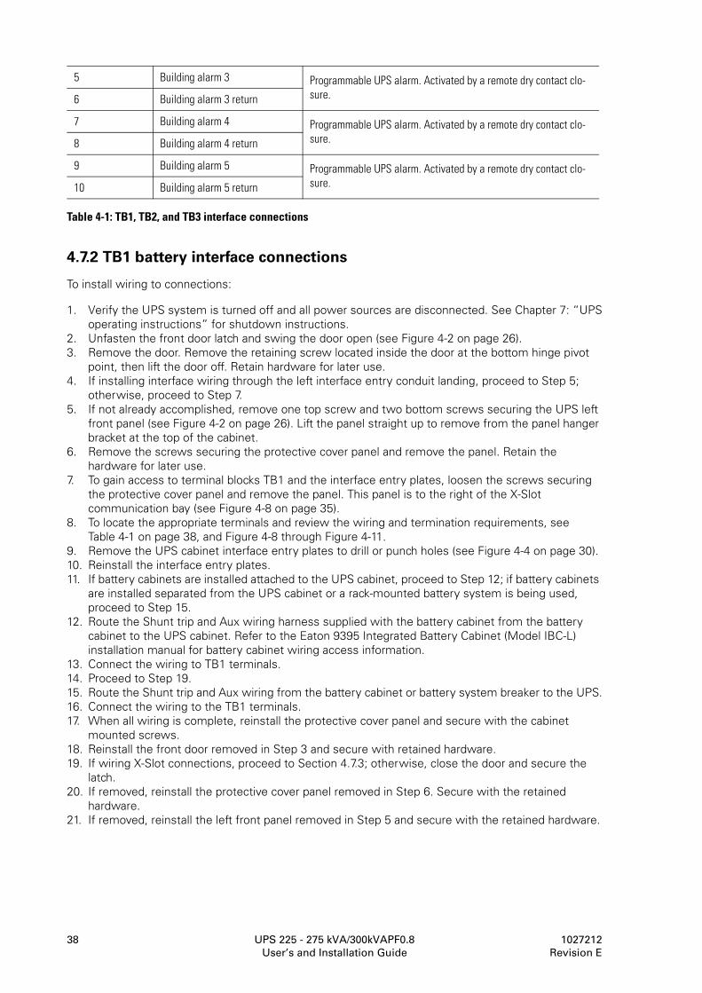
Table 4-1: TB1, TB2, and TB3 interface connections
4.7.2 TB1 battery interface connections
To install wiring to connections:
1. Verify the UPS system is turned off and all power sources are disconnected. See Chapter 7: “UPSoperating instructions” for shutdown instructions.
2. Unfasten the front door latch and swing the door open (see Figure 4-2 on page 26).3. Remove the door. Remove the retaining screw located inside the door at the bottom hinge pivot
point, then lift the door off. Retain hardware for later use.4. If installing interface wiring through the left interface entry conduit landing, proceed to Step 5;
otherwise, proceed to Step 7.5. If not already accomplished, remove one top screw and two bottom screws securing the UPS left
front panel (see Figure 4-2 on page 26). Lift the panel straight up to remove from the panel hanger bracket at the top of the cabinet.
6. Remove the screws securing the protective cover panel and remove the panel. Retain the hardware for later use.
7. To gain access to terminal blocks TB1 and the interface entry plates, loosen the screws securing the protective cover panel and remove the panel. This panel is to the right of the X-Slot communication bay (see Figure 4-8 on page 35).
8. To locate the appropriate terminals and review the wiring and termination requirements, see Table 4-1 on page 38, and Figure 4-8 through Figure 4-11.
9. Remove the UPS cabinet interface entry plates to drill or punch holes (see Figure 4-4 on page 30).10. Reinstall the interface entry plates.11. If battery cabinets are installed attached to the UPS cabinet, proceed to Step 12; if battery cabinets
are installed separated from the UPS cabinet or a rack-mounted battery system is being used, proceed to Step 15.
12. Route the Shunt trip and Aux wiring harness supplied with the battery cabinet from the battery cabinet to the UPS cabinet. Refer to the Eaton 9395 Integrated Battery Cabinet (Model IBC-L) installation manual for battery cabinet wiring access information.
13. Connect the wiring to TB1 terminals.14. Proceed to Step 19.15. Route the Shunt trip and Aux wiring from the battery cabinet or battery system breaker to the UPS.16. Connect the wiring to the TB1 terminals.17. When all wiring is complete, reinstall the protective cover panel and secure with the cabinet
mounted screws.18. Reinstall the front door removed in Step 3 and secure with retained hardware.19. If wiring X-Slot connections, proceed to Section 4.7.3; otherwise, close the door and secure the
latch.20. If removed, reinstall the protective cover panel removed in Step 6. Secure with the retained
hardware.21. If removed, reinstall the left front panel removed in Step 5 and secure with the retained hardware.
5 Building alarm 3 Programmable UPS alarm. Activated by a remote dry contact clo-sure.6 Building alarm 3 return
7 Building alarm 4 Programmable UPS alarm. Activated by a remote dry contact clo-sure.8 Building alarm 4 return
9 Building alarm 5 Programmable UPS alarm. Activated by a remote dry contact clo-sure.10 Building alarm 5 return
38 UPS 225 - 275 kVA/300kVAPF0.8 1027212User’s and Installation Guide Revision E
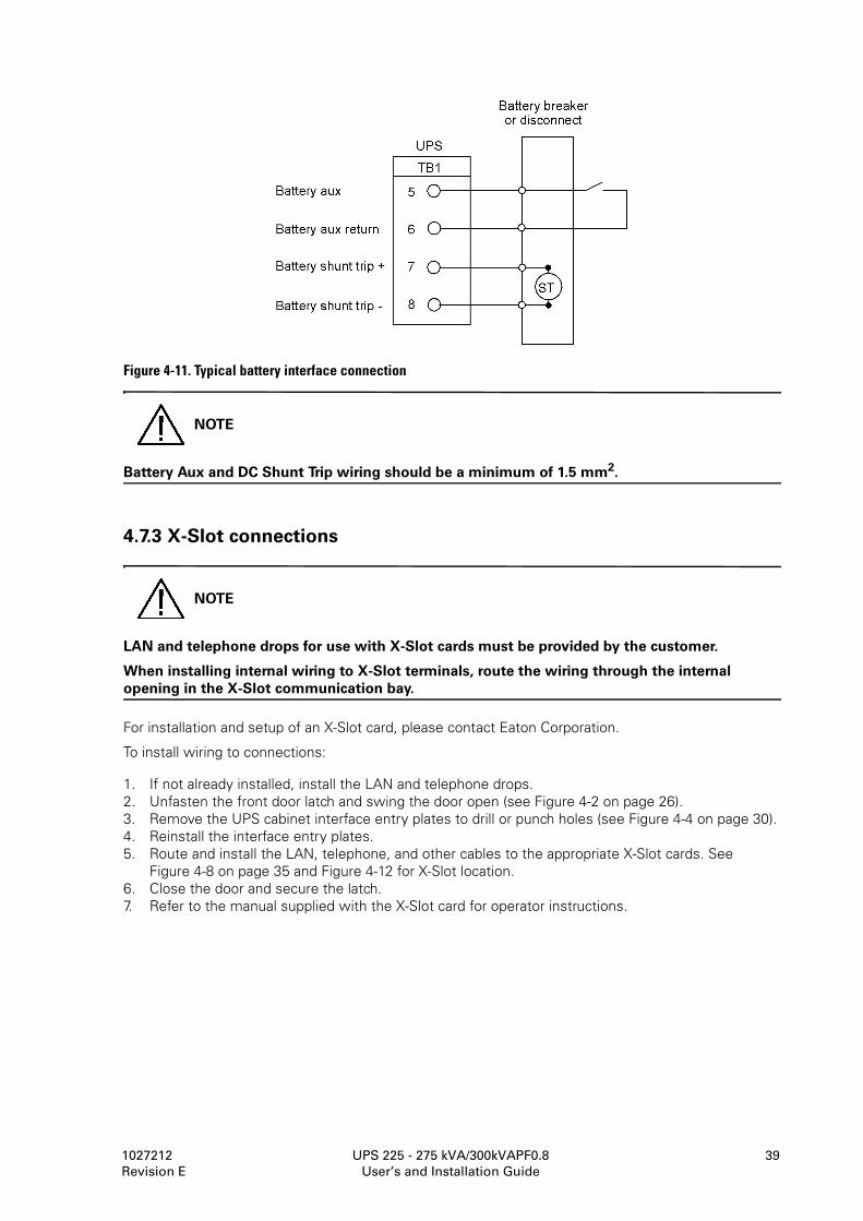
Figure 4-11. Typical battery interface connection
NOTE
Battery Aux and DC Shunt Trip wiring should be a minimum of 1.5 mm2.
4.7.3 X-Slot connections
NOTE
LAN and telephone drops for use with X-Slot cards must be provided by the customer.
When installing internal wiring to X-Slot terminals, route the wiring through the internal
opening in the X-Slot communication bay.
For installation and setup of an X-Slot card, please contact Eaton Corporation.
To install wiring to connections:
1. If not already installed, install the LAN and telephone drops.2. Unfasten the front door latch and swing the door open (see Figure 4-2 on page 26).3. Remove the UPS cabinet interface entry plates to drill or punch holes (see Figure 4-4 on page 30).4. Reinstall the interface entry plates.5. Route and install the LAN, telephone, and other cables to the appropriate X-Slot cards. See
Figure 4-8 on page 35 and Figure 4-12 for X-Slot location.6. Close the door and secure the latch.7. Refer to the manual supplied with the X-Slot card for operator instructions.
1027212 UPS 225 - 275 kVA/300kVAPF0.8 39Revision E User’s and Installation Guide
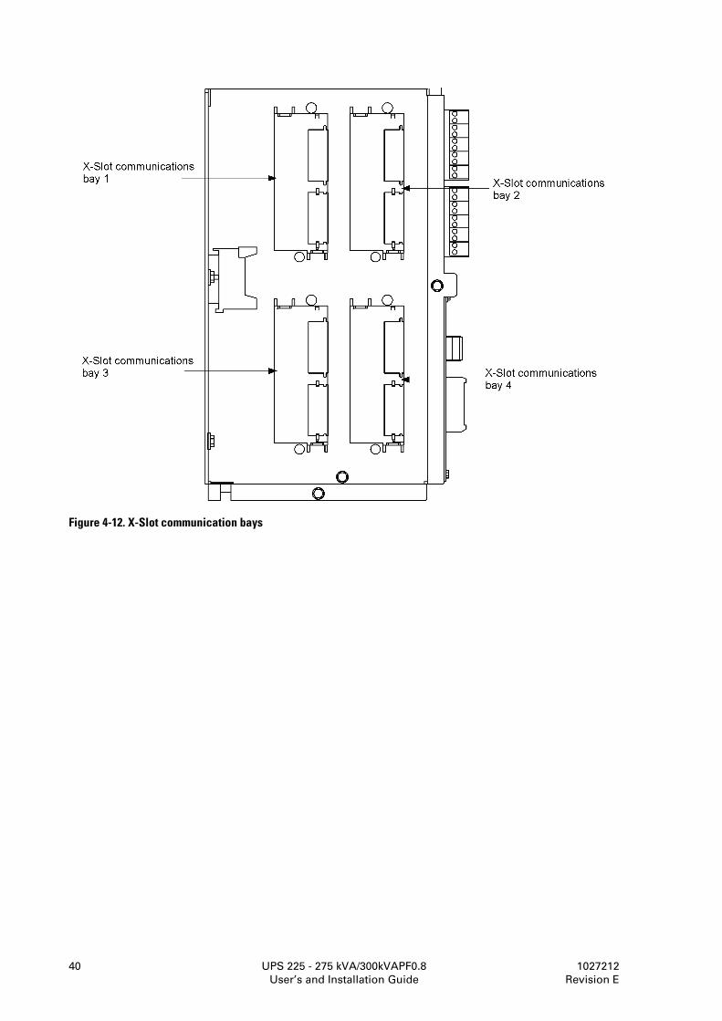
Figure 4-12. X-Slot communication bays
40 UPS 225 - 275 kVA/300kVAPF0.8 1027212User’s and Installation Guide Revision E
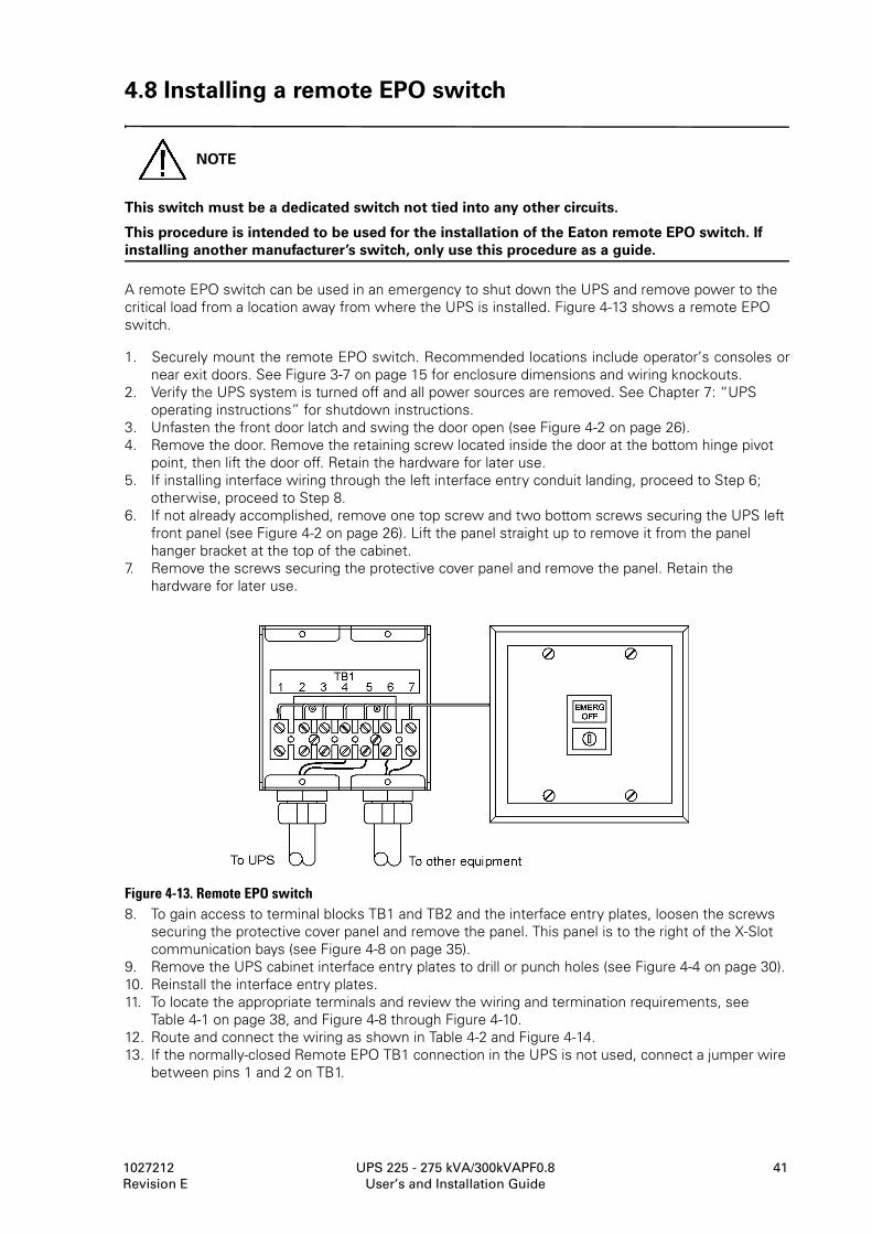
4.8 Installing a remote EPO switch
NOTE
This switch must be a dedicated switch not tied into any other circuits.
This procedure is intended to be used for the installation of the Eaton remote EPO switch. If
installing another manufacturer’s switch, only use this procedure as a guide.
A remote EPO switch can be used in an emergency to shut down the UPS and remove power to the critical load from a location away from where the UPS is installed. Figure 4-13 shows a remote EPO switch.
1. Securely mount the remote EPO switch. Recommended locations include operator’s consoles ornear exit doors. See Figure 3-7 on page 15 for enclosure dimensions and wiring knockouts.
2. Verify the UPS system is turned off and all power sources are removed. See Chapter 7: “UPS operating instructions” for shutdown instructions.
3. Unfasten the front door latch and swing the door open (see Figure 4-2 on page 26).4. Remove the door. Remove the retaining screw located inside the door at the bottom hinge pivot
point, then lift the door off. Retain the hardware for later use.5. If installing interface wiring through the left interface entry conduit landing, proceed to Step 6;
otherwise, proceed to Step 8.6. If not already accomplished, remove one top screw and two bottom screws securing the UPS left
front panel (see Figure 4-2 on page 26). Lift the panel straight up to remove it from the panel hanger bracket at the top of the cabinet.
7. Remove the screws securing the protective cover panel and remove the panel. Retain the hardware for later use.
Figure 4-13. Remote EPO switch8. To gain access to terminal blocks TB1 and TB2 and the interface entry plates, loosen the screws
securing the protective cover panel and remove the panel. This panel is to the right of the X-Slot communication bays (see Figure 4-8 on page 35).
9. Remove the UPS cabinet interface entry plates to drill or punch holes (see Figure 4-4 on page 30).10. Reinstall the interface entry plates.11. To locate the appropriate terminals and review the wiring and termination requirements, see
Table 4-1 on page 38, and Figure 4-8 through Figure 4-10.12. Route and connect the wiring as shown in Table 4-2 and Figure 4-14.13. If the normally-closed Remote EPO TB1 connection in the UPS is not used, connect a jumper wire
between pins 1 and 2 on TB1.
1027212 UPS 225 - 275 kVA/300kVAPF0.8 41Revision E User’s and Installation Guide
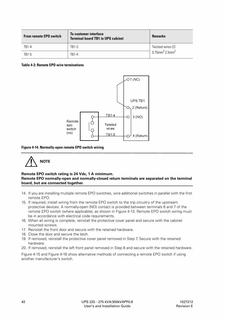
Table 4-2: Remote EPO wire terminations
Figure 4-14. Normally-open remote EPO switch wiring
NOTE
Remote EPO switch rating is 24 Vdc, 1 A minimum.
Remote EPO normally-open and normally-closed return terminals are separated on the terminal
board, but are connected together.
14. If you are installing multiple remote EPO switches, wire additional switches in parallel with the first remote EPO.
15. If required, install wiring from the remote EPO switch to the trip circuitry of the upstream protective devices. A normally-open (NO) contact is provided between terminals 6 and 7 of the remote EPO switch (where applicable), as shown in Figure 4-13. Remote EPO switch wiring must be in accordance with electrical code requirements.
16. When all wiring is complete, reinstall the protective cover panel and secure with the cabinet mounted screws.
17. Reinstall the front door and secure with the retained hardware.18. Close the door and secure the latch.19. If removed, reinstall the protective cover panel removed in Step 7. Secure with the retained
hardware.20. If removed, reinstall the left front panel removed in Step 6 and secure with the retained hardware.
Figure 4-15 and Figure 4-16 show alternative methods of connecting a remote EPO switch if using another manufacturer’s switch.
From remote EPO switch To customer interfaceTerminal board TB1 in UPS cabinet Remarks
TB1-4 TB1-3 Twisted wires (2)0.75mm2 2.5mm2
TB1-5 TB1-4
42 UPS 225 - 275 kVA/300kVAPF0.8 1027212User’s and Installation Guide Revision E

Figure 4-15. Normally-closed remote EPO switch wiring
NOTE
Remote EPO switch rating is 24 Vdc, 1 A minimum.
Remote EPO normally-open and normally-closed return terminals are separated on the terminal
board, but are connected together.
Figure 4-16. Normally closed and normally open remote EPO switch wiring
NOTE
Remote EPO switch rating is 24 Vdc, 1 A minimum.
Remote EPO normally-open and normally-closed return terminals are separated on the terminal
board, but are connected together.
1027212 UPS 225 - 275 kVA/300kVAPF0.8 43Revision E User’s and Installation Guide
44 UPS 225 - 275 kVA/300kVAPF0.8 1027212User’s and Installation Guide Revision E
4.9 Installing options, accessories, and distributed bypass
control wiring
To install options, accessories, and distributed bypass control wiring, see Chapter 5: “Installing options and accessories”.
4.10 Initial startup
Startup and operational checks must be performed by an authorized Eaton Customer Service Engineer, or the warranty terms specified on page 124 become void. This service is offered as part of the sales contract for the UPS. Contact service in advance (usually a two-week notice is required) to reserve a preferred startup date.
4.11 Completing the installation checklist
The final step in installing the UPS system is completing the installation checklist at the end of this manual. This checklist ensures that you have completely installed all hardware, cables, and other equipment. Complete all items listed on the checklist to ensure a smooth installation. Make a copy of the installation checklist before filling it out, and retain the original. If installing a parallel system, complete the parallel system installation checklist in addition to the installation checklist.
After the installation is complete, your service representative must verify the operation of the UPS system and commission it to support the critical load. The service representative does not perform any installation tasks other than verifying software and operating setup parameters. Service personnel may request a copy of the completed installation checklist to verify all applicable equipment installations have been completed.
NOTE
The installation checklist MUST be completed prior to starting the UPS system for the first time.
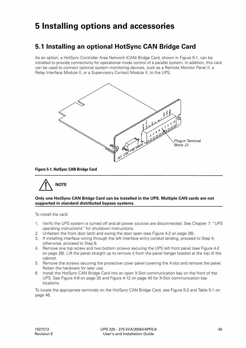
5 Installing options and accessories
5.1 Installing an optional HotSync CAN Bridge Card
As an option, a HotSync Controller Area Network (CAN) Bridge Card, shown in Figure 5-1, can be installed to provide connectivity for operational mode control of a parallel system. In addition, this card can be used to connect optional system monitoring devices, such as a Remote Monitor Panel II, a Relay Interface Module II, or a Supervisory Contact Module II, to the UPS.
Figure 5-1. HotSync CAN Bridge Card
NOTE
Only one HotSync CAN Bridge Card can be installed in the UPS. Multiple CAN cards are not
supported in standard distributed bypass systems.
To install the card:
1. Verify the UPS system is turned off and all power sources are disconnected. See Chapter 7: “UPSoperating instructions” for shutdown instructions.
2. Unfasten the front door latch and swing the door open (see Figure 4-2 on page 26).3. If installing interface wiring through the left interface entry conduit landing, proceed to Step 4;
otherwise, proceed to Step 6.4. Remove one top screw and two bottom screws securing the UPS left front panel (see Figure 4-2
on page 26). Lift the panel straight up to remove it from the panel hanger bracket at the top of the cabinet.
5. Remove the screws securing the protective cover panel covering the X-slot and remove the panel. Retain the hardware for later use.
6. Install the HotSync CAN Bridge Card into an open X-Slot communication bay on the front of the UPS. See Figure 4-8 on page 35 and Figure 4-12 on page 40 for X-Slot communication bay locations.
To locate the appropriate terminals on the HotSync CAN Bridge Card, see Figure 5-2 and Table 5-1 on page 46.
1027212 UPS 225 - 275 kVA/300kVAPF0.8 45Revision E User’s and Installation Guide
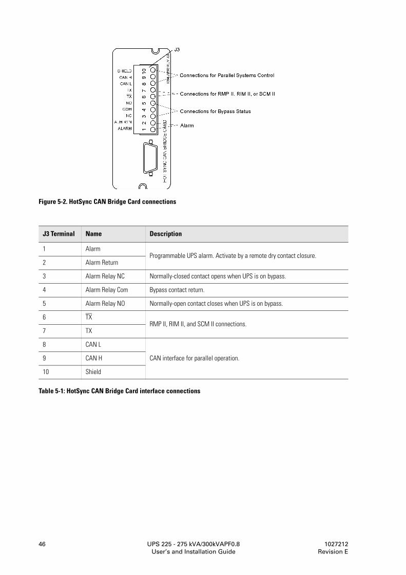
Figure 5-2. HotSync CAN Bridge Card connections
Table 5-1: HotSync CAN Bridge Card interface connections
J3 Terminal Name Description
1 AlarmProgrammable UPS alarm. Activate by a remote dry contact closure.
2 Alarm Return
3 Alarm Relay NC Normally-closed contact opens when UPS is on bypass.
4 Alarm Relay Com Bypass contact return.
5 Alarm Relay NO Normally-open contact closes when UPS is on bypass.
6 TXRMP II, RIM II, and SCM II connections.
7 TX
8 CAN L
CAN interface for parallel operation.9 CAN H
10 Shield
46 UPS 225 - 275 kVA/300kVAPF0.8 1027212User’s and Installation Guide Revision E
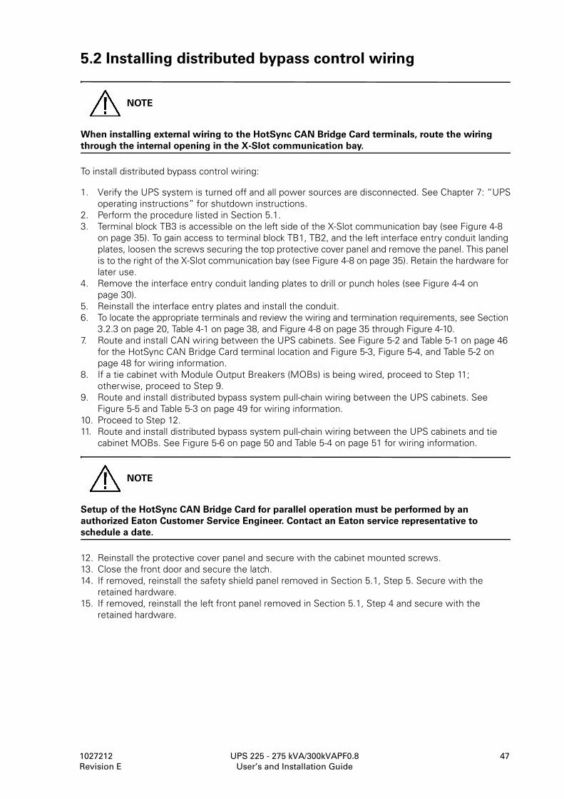
5.2 Installing distributed bypass control wiring
NOTE
When installing external wiring to the HotSync CAN Bridge Card terminals, route the wiring
through the internal opening in the X-Slot communication bay.
To install distributed bypass control wiring:
1. Verify the UPS system is turned off and all power sources are disconnected. See Chapter 7: “UPSoperating instructions” for shutdown instructions.
2. Perform the procedure listed in Section 5.1.3. Terminal block TB3 is accessible on the left side of the X-Slot communication bay (see Figure 4-8
on page 35). To gain access to terminal block TB1, TB2, and the left interface entry conduit landing plates, loosen the screws securing the top protective cover panel and remove the panel. This panel is to the right of the X-Slot communication bay (see Figure 4-8 on page 35). Retain the hardware for later use.
4. Remove the interface entry conduit landing plates to drill or punch holes (see Figure 4-4 on page 30).
5. Reinstall the interface entry plates and install the conduit.6. To locate the appropriate terminals and review the wiring and termination requirements, see Section
3.2.3 on page 20, Table 4-1 on page 38, and Figure 4-8 on page 35 through Figure 4-10.7. Route and install CAN wiring between the UPS cabinets. See Figure 5-2 and Table 5-1 on page 46
for the HotSync CAN Bridge Card terminal location and Figure 5-3, Figure 5-4, and Table 5-2 on page 48 for wiring information.
8. If a tie cabinet with Module Output Breakers (MOBs) is being wired, proceed to Step 11; otherwise, proceed to Step 9.
9. Route and install distributed bypass system pull-chain wiring between the UPS cabinets. See Figure 5-5 and Table 5-3 on page 49 for wiring information.
10. Proceed to Step 12.11. Route and install distributed bypass system pull-chain wiring between the UPS cabinets and tie
cabinet MOBs. See Figure 5-6 on page 50 and Table 5-4 on page 51 for wiring information.
NOTE
Setup of the HotSync CAN Bridge Card for parallel operation must be performed by an
authorized Eaton Customer Service Engineer. Contact an Eaton service representative to
schedule a date.
12. Reinstall the protective cover panel and secure with the cabinet mounted screws.13. Close the front door and secure the latch.14. If removed, reinstall the safety shield panel removed in Section 5.1, Step 5. Secure with the
retained hardware.15. If removed, reinstall the left front panel removed in Section 5.1, Step 4 and secure with the
retained hardware.
1027212 UPS 225 - 275 kVA/300kVAPF0.8 47Revision E User’s and Installation Guide
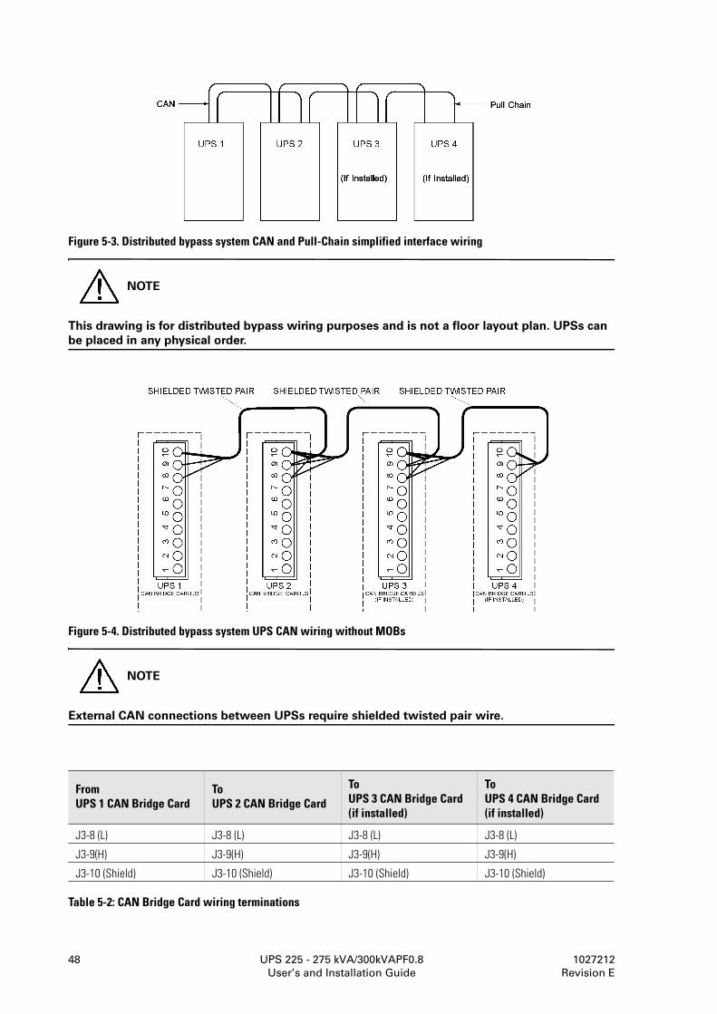
Figure 5-3. Distributed bypass system CAN and Pull-Chain simplified interface wiring
NOTE
This drawing is for distributed bypass wiring purposes and is not a floor layout plan. UPSs can
be placed in any physical order.
Figure 5-4. Distributed bypass system UPS CAN wiring without MOBs
NOTE
External CAN connections between UPSs require shielded twisted pair wire.
Table 5-2: CAN Bridge Card wiring terminations
FromUPS 1 CAN Bridge Card
ToUPS 2 CAN Bridge Card
ToUPS 3 CAN Bridge Card(if installed)
ToUPS 4 CAN Bridge Card(if installed)
J3-8 (L) J3-8 (L) J3-8 (L) J3-8 (L)
J3-9(H) J3-9(H) J3-9(H) J3-9(H)
J3-10 (Shield) J3-10 (Shield) J3-10 (Shield) J3-10 (Shield)
48 UPS 225 - 275 kVA/300kVAPF0.8 1027212User’s and Installation Guide Revision E
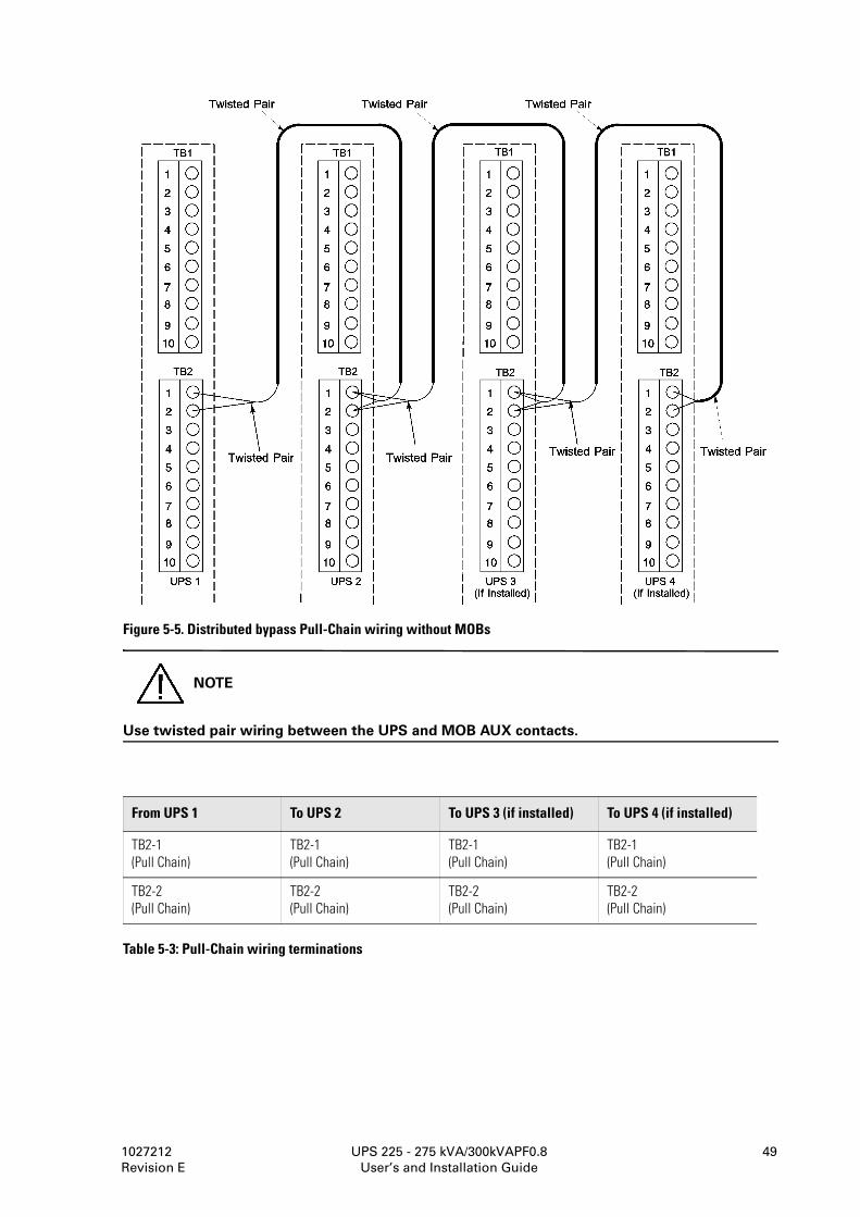
Figure 5-5. Distributed bypass Pull-Chain wiring without MOBs
NOTE
Use twisted pair wiring between the UPS and MOB AUX contacts.
Table 5-3: Pull-Chain wiring terminations
From UPS 1 To UPS 2 To UPS 3 (if installed) To UPS 4 (if installed)
TB2-1(Pull Chain)
TB2-1(Pull Chain)
TB2-1(Pull Chain)
TB2-1(Pull Chain)
TB2-2(Pull Chain)
TB2-2(Pull Chain)
TB2-2(Pull Chain)
TB2-2(Pull Chain)
1027212 UPS 225 - 275 kVA/300kVAPF0.8 49Revision E User’s and Installation Guide
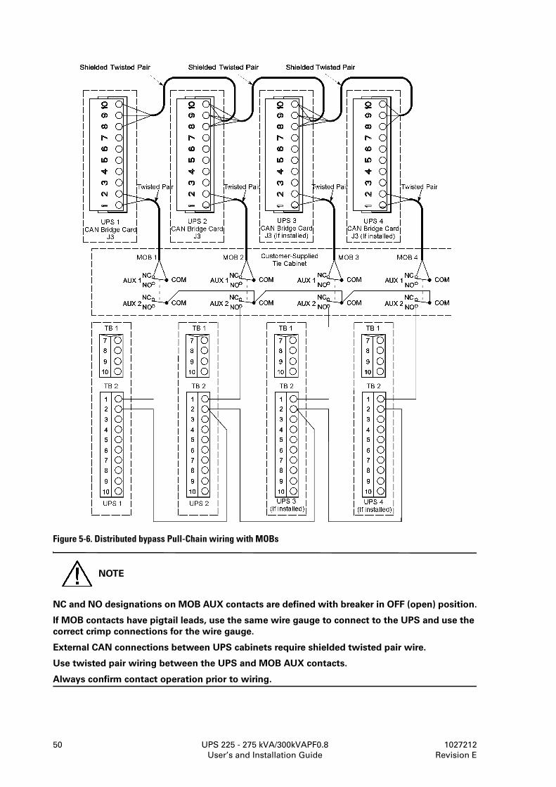
Figure 5-6. Distributed bypass Pull-Chain wiring with MOBs
NOTE
NC and NO designations on MOB AUX contacts are defined with breaker in OFF (open) position.
If MOB contacts have pigtail leads, use the same wire gauge to connect to the UPS and use the
correct crimp connections for the wire gauge.
External CAN connections between UPS cabinets require shielded twisted pair wire.
Use twisted pair wiring between the UPS and MOB AUX contacts.
Always confirm contact operation prior to wiring.
50 UPS 225 - 275 kVA/300kVAPF0.8 1027212User’s and Installation Guide Revision E
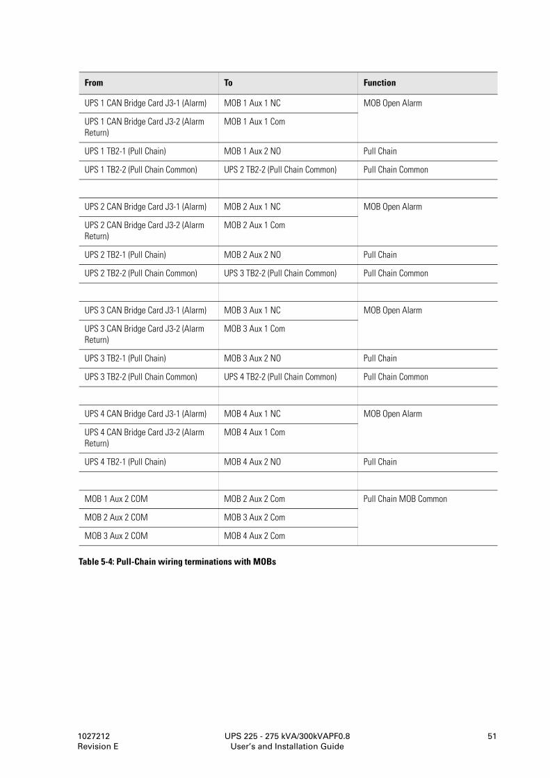
Table 5-4: Pull-Chain wiring terminations with MOBs
From To Function
UPS 1 CAN Bridge Card J3-1 (Alarm) MOB 1 Aux 1 NC MOB Open Alarm
UPS 1 CAN Bridge Card J3-2 (Alarm Return)
MOB 1 Aux 1 Com
UPS 1 TB2-1 (Pull Chain) MOB 1 Aux 2 NO Pull Chain
UPS 1 TB2-2 (Pull Chain Common) UPS 2 TB2-2 (Pull Chain Common) Pull Chain Common
UPS 2 CAN Bridge Card J3-1 (Alarm) MOB 2 Aux 1 NC MOB Open Alarm
UPS 2 CAN Bridge Card J3-2 (Alarm Return)
MOB 2 Aux 1 Com
UPS 2 TB2-1 (Pull Chain) MOB 2 Aux 2 NO Pull Chain
UPS 2 TB2-2 (Pull Chain Common) UPS 3 TB2-2 (Pull Chain Common) Pull Chain Common
UPS 3 CAN Bridge Card J3-1 (Alarm) MOB 3 Aux 1 NC MOB Open Alarm
UPS 3 CAN Bridge Card J3-2 (Alarm Return)
MOB 3 Aux 1 Com
UPS 3 TB2-1 (Pull Chain) MOB 3 Aux 2 NO Pull Chain
UPS 3 TB2-2 (Pull Chain Common) UPS 4 TB2-2 (Pull Chain Common) Pull Chain Common
UPS 4 CAN Bridge Card J3-1 (Alarm) MOB 4 Aux 1 NC MOB Open Alarm
UPS 4 CAN Bridge Card J3-2 (Alarm Return)
MOB 4 Aux 1 Com
UPS 4 TB2-1 (Pull Chain) MOB 4 Aux 2 NO Pull Chain
MOB 1 Aux 2 COM MOB 2 Aux 2 Com Pull Chain MOB Common
MOB 2 Aux 2 COM MOB 3 Aux 2 Com
MOB 3 Aux 2 COM MOB 4 Aux 2 Com
1027212 UPS 225 - 275 kVA/300kVAPF0.8 51Revision E User’s and Installation Guide
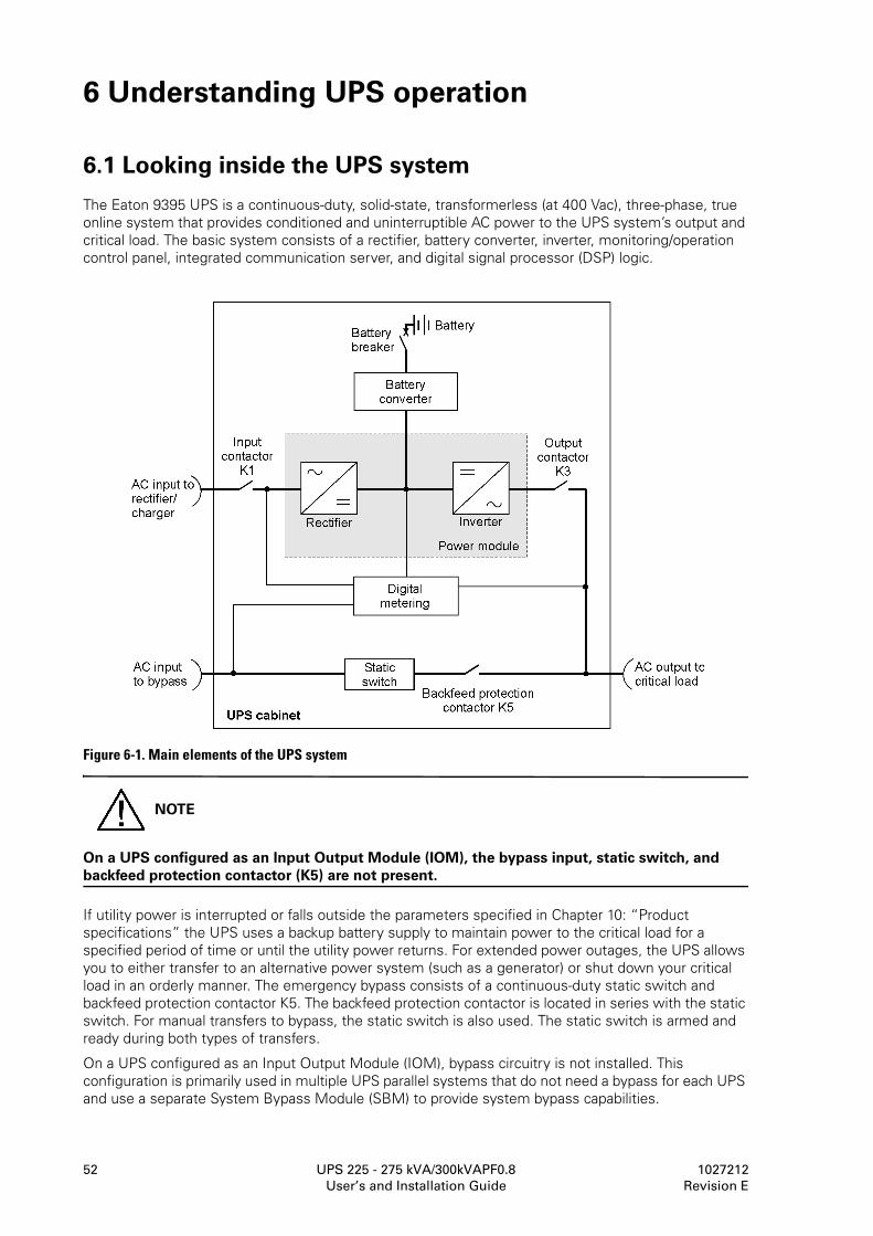
52 UPS 225 - 275 kVA/300kVAPF0.8 1027212User’s and Installation Guide Revision E
6 Understanding UPS operation
6.1 Looking inside the UPS system
The Eaton 9395 UPS is a continuous-duty, solid-state, transformerless (at 400 Vac), three-phase, true online system that provides conditioned and uninterruptible AC power to the UPS system’s output and critical load. The basic system consists of a rectifier, battery converter, inverter, monitoring/operation control panel, integrated communication server, and digital signal processor (DSP) logic.
Figure 6-1. Main elements of the UPS system
NOTE
On a UPS configured as an Input Output Module (IOM), the bypass input, static switch, and
backfeed protection contactor (K5) are not present.
If utility power is interrupted or falls outside the parameters specified in Chapter 10: “Product specifications” the UPS uses a backup battery supply to maintain power to the critical load for a specified period of time or until the utility power returns. For extended power outages, the UPS allows you to either transfer to an alternative power system (such as a generator) or shut down your critical load in an orderly manner. The emergency bypass consists of a continuous-duty static switch and backfeed protection contactor K5. The backfeed protection contactor is located in series with the static switch. For manual transfers to bypass, the static switch is also used. The static switch is armed and ready during both types of transfers.
On a UPS configured as an Input Output Module (IOM), bypass circuitry is not installed. This configuration is primarily used in multiple UPS parallel systems that do not need a bypass for each UPS and use a separate System Bypass Module (SBM) to provide system bypass capabilities.
6.2 Single UPS
A single UPS operates independently to support an applied load from the inverter, providing conditioned and uninterruptible AC power to the critical load from the output of the module. During an outage, the inverter continues to operate, supporting power to the load from the battery supply. If the unit requires service, applied loads are transferred to the internal bypass via the continuous-duty static switch either automatically or manually. With the exception of a battery cabinet, no other cabinets or equipment are required for the single UPS to successfully support its applied loads.
6.2.1 Modes
The Eaton 9395 UPS supports a critical load in five different modes of operation. The UPS can automatically use all five modes, as required.
NOTE
The Variable Module Management System and Energy Saver System modes are mutually
exclusive.
The standard operation modes are:
• In Normal mode, the critical load is supplied by the inverter, which derives its power from rectified utility AC power. In this mode, the battery charger also provides charging current for the battery, if needed.
• In Battery mode, the battery provides DC power, which maintains inverter operation. The battery supports the critical load.
• In Bypass mode, the critical load is directly supported by utility power.
• In Variable Module Management System (VMMS) mode, the UPS operates as a traditional double-conversion UPS, but selectively shifts the load to fewer UPMs to increase the efficiency of the UPS.
• In Energy Saver System (ESS) mode, the critical load is directly supported by utility power, but with the ability to automatically switch to Normal mode if an abnormal condition is detected.
The following sections describe the differences in the five UPS operating modes, using block diagrams to show the power flow during each mode of operation.
6.2.2 Normal mode
Figure 6-2 shows the path of electrical power through the UPS system when the UPS is operating in normal mode.
NOTE
On a UPS configured as an IOM, the bypass input, static switch, and K5 are not present.
1027212 UPS 225 - 275 kVA/300kVAPF0.8 53Revision E User’s and Installation Guide
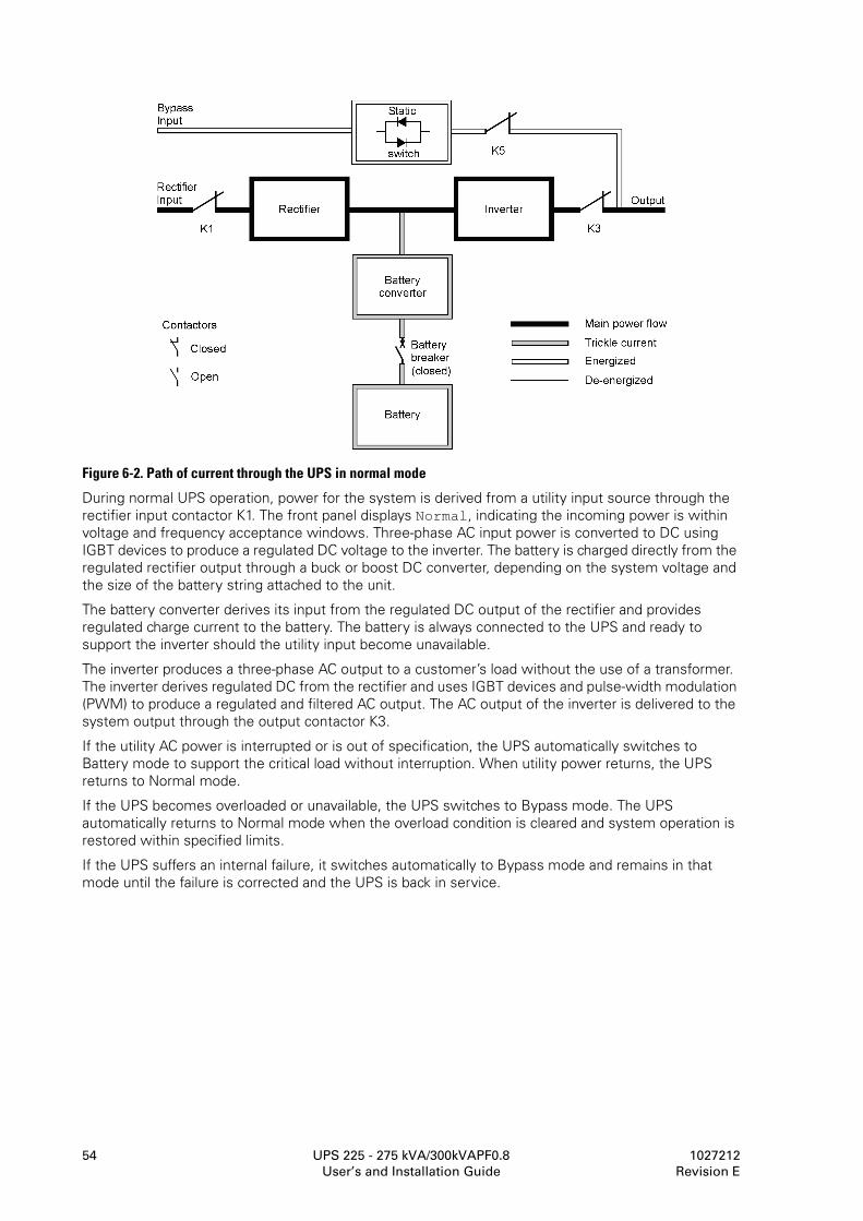
Figure 6-2. Path of current through the UPS in normal mode
During normal UPS operation, power for the system is derived from a utility input source through the rectifier input contactor K1. The front panel displays Normal, indicating the incoming power is within voltage and frequency acceptance windows. Three-phase AC input power is converted to DC using IGBT devices to produce a regulated DC voltage to the inverter. The battery is charged directly from the regulated rectifier output through a buck or boost DC converter, depending on the system voltage and the size of the battery string attached to the unit.
The battery converter derives its input from the regulated DC output of the rectifier and provides regulated charge current to the battery. The battery is always connected to the UPS and ready to support the inverter should the utility input become unavailable.
The inverter produces a three-phase AC output to a customer’s load without the use of a transformer. The inverter derives regulated DC from the rectifier and uses IGBT devices and pulse-width modulation (PWM) to produce a regulated and filtered AC output. The AC output of the inverter is delivered to the system output through the output contactor K3.
If the utility AC power is interrupted or is out of specification, the UPS automatically switches to Battery mode to support the critical load without interruption. When utility power returns, the UPS returns to Normal mode.
If the UPS becomes overloaded or unavailable, the UPS switches to Bypass mode. The UPS automatically returns to Normal mode when the overload condition is cleared and system operation is restored within specified limits.
If the UPS suffers an internal failure, it switches automatically to Bypass mode and remains in that mode until the failure is corrected and the UPS is back in service.
54 UPS 225 - 275 kVA/300kVAPF0.8 1027212User’s and Installation Guide Revision E
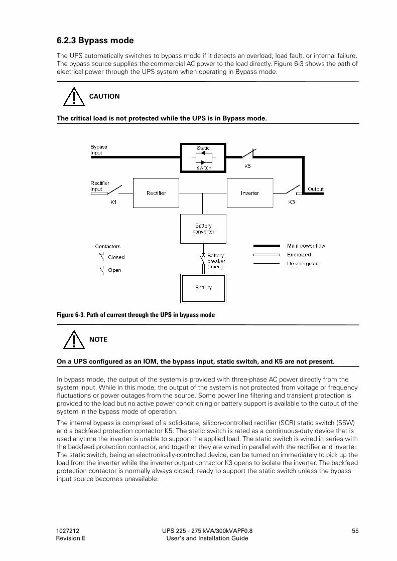
6.2.3 Bypass mode
The UPS automatically switches to bypass mode if it detects an overload, load fault, or internal failure. The bypass source supplies the commercial AC power to the load directly. Figure 6-3 shows the path of electrical power through the UPS system when operating in Bypass mode.
CAUTION
The critical load is not protected while the UPS is in Bypass mode.
Figure 6-3. Path of current through the UPS in bypass mode
NOTE
On a UPS configured as an IOM, the bypass input, static switch, and K5 are not present.
In bypass mode, the output of the system is provided with three-phase AC power directly from the system input. While in this mode, the output of the system is not protected from voltage or frequency fluctuations or power outages from the source. Some power line filtering and transient protection is provided to the load but no active power conditioning or battery support is available to the output of the system in the bypass mode of operation.
The internal bypass is comprised of a solid-state, silicon-controlled rectifier (SCR) static switch (SSW) and a backfeed protection contactor K5. The static switch is rated as a continuous-duty device that is used anytime the inverter is unable to support the applied load. The static switch is wired in series with the backfeed protection contactor, and together they are wired in parallel with the rectifier and inverter. The static switch, being an electronically-controlled device, can be turned on immediately to pick up the load from the inverter while the inverter output contactor K3 opens to isolate the inverter. The backfeed protection contactor is normally always closed, ready to support the static switch unless the bypass input source becomes unavailable.
1027212 UPS 225 - 275 kVA/300kVAPF0.8 55Revision E User’s and Installation Guide
6.2.4 Variable Module Management System
NOTE
VMMS and ESS modes are mutually exclusive. If VMMS mode is enabled, ESS mode is
disabled.
In VMMS mode, the UPS operates as a traditional double-conversion UPS. However, the UPS will selectively shift the load to fewer UPMs based on the required load in order to force the remaining UPMs to carry a higher load. The efficiency rating for each UPM is highest when loads are greater than 50% of the UPM rating. Therefore, with multiple UPMs, a UPS can achieve higher efficiencies for lighter loads.
When a UPM is inactivated by VMMS mode, the UPM will stop gating the inverter and rectifier and keep the output contactor closed in order to maintain voltage match and phase lock to the critical bus. In this mode the UPS actively monitors the critical bus, keeping the UPM input contactor closed in order to keep the DC link primed (through the rectifier diodes) and also to allow the UPM to immediately return to active mode in the event of a disturbance or load step on the critical bus.
VMMS limits the maximum power available from a UPM when in VMMS mode. The default setting is 80% of the UPM full power rating. If the limit is exceeded, additional UPMs are activated to take on the increased load. The VMMS redundancy setting sets the number of redundant UPMs that the customer requires. Both the VMMS UPM load limit and UPM redundancy are user-configurable.
In High Alert mode, the UPS defaults to double-conversion Online mode and all UPMs go active for one hour (user-configurable). At the end of the hour, the UPS defaults back to VMMS mode. If the High Alert mode is reactivated during the one hour, the one hour timer will be restarted.
6.2.5 Energy Saver System (ESS)
NOTE
VMMS and ESS modes are mutually exclusive. If ESS mode is enabled, VMMS mode is
disabled.
When the UPS is operating in Energy Saver System, the bypass source supplies the commercial AC power to the load directly through the static switch. Some power line filtering and transient protection is provided to the load but no active power conditioning or battery support is available. All power converters are off and are in the ready state (in case a forward transfer is needed). During this mode, the output contactor is closed and the link is maintained through the diode bridge. Figure 6-4 shows the path of electrical power through the UPS system when operating in Energy Saver System.
56 UPS 225 - 275 kVA/300kVAPF0.8 1027212User’s and Installation Guide Revision E
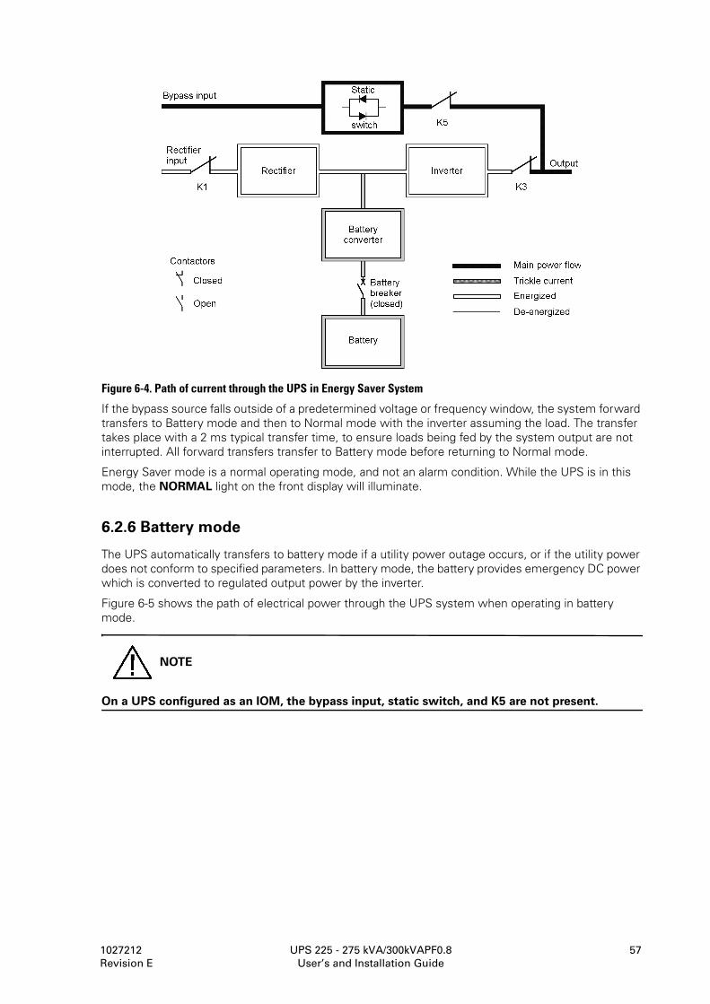
Figure 6-4. Path of current through the UPS in Energy Saver System
If the bypass source falls outside of a predetermined voltage or frequency window, the system forward transfers to Battery mode and then to Normal mode with the inverter assuming the load. The transfer takes place with a 2 ms typical transfer time, to ensure loads being fed by the system output are not interrupted. All forward transfers transfer to Battery mode before returning to Normal mode.
Energy Saver mode is a normal operating mode, and not an alarm condition. While the UPS is in this mode, the NORMAL light on the front display will illuminate.
6.2.6 Battery mode
The UPS automatically transfers to battery mode if a utility power outage occurs, or if the utility power does not conform to specified parameters. In battery mode, the battery provides emergency DC power which is converted to regulated output power by the inverter.
Figure 6-5 shows the path of electrical power through the UPS system when operating in battery mode.
NOTE
On a UPS configured as an IOM, the bypass input, static switch, and K5 are not present.
1027212 UPS 225 - 275 kVA/300kVAPF0.8 57Revision E User’s and Installation Guide
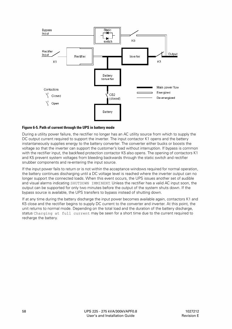
Figure 6-5. Path of current through the UPS in battery mode
During a utility power failure, the rectifier no longer has an AC utility source from which to supply the DC output current required to support the inverter. The input contactor K1 opens and the battery instantaneously supplies energy to the battery converter. The converter either bucks or boosts the voltage so that the inverter can support the customer’s load without interruption. If bypass is common with the rectifier input, the backfeed protection contactor K5 also opens. The opening of contactors K1 and K5 prevent system voltages from bleeding backwards through the static switch and rectifier snubber components and re-entering the input source.
If the input power fails to return or is not within the acceptance windows required for normal operation, the battery continues discharging until a DC voltage level is reached where the inverter output can no longer support the connected loads. When this event occurs, the UPS issues another set of audible and visual alarms indicating SHUTDOWN IMMINENT. Unless the rectifier has a valid AC input soon, the output can be supported for only two minutes before the output of the system shuts down. If the bypass source is available, the UPS transfers to bypass instead of shutting down.
If at any time during the battery discharge the input power becomes available again, contactors K1 and K5 close and the rectifier begins to supply DC current to the converter and inverter. At this point, the unit returns to normal mode. Depending on the total load and the duration of the battery discharge, status Charging at full current may be seen for a short time due to the current required to recharge the battery.
58 UPS 225 - 275 kVA/300kVAPF0.8 1027212User’s and Installation Guide Revision E
6.3 UPS system oneline configurations
The system oneline drawings in this section show the simplified internal structure of the UPS, battery supply, and basic maintenance bypass.
NOTE
Callout letters A, B, C, and D map to Table 3-4 on page 16.
Oneline drawing UPS model
VoltageSystem type
Input Output
Figure 6-6 on page 60
9395-275/225300kVAPF0.8
400 400 Single module - Reverse transfer dual-feed
Figure 6-7 on page 61
9395-275/275300kVAPF0.8
400 400 Single module - Reverse transfer dual-feed with typical maintenance bypass panel
1027212 UPS 225 - 275 kVA/300kVAPF0.8 59Revision E User’s and Installation Guide
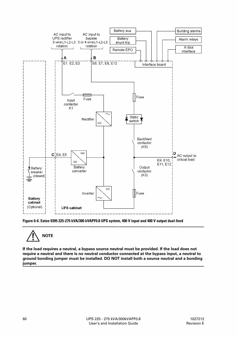
Figure 6-6. Eaton 9395 225-275 kVA/300 kVAPF0.8 UPS system, 400 V input and 400 V output dual-feed
NOTE
If the load requires a neutral, a bypass source neutral must be provided. If the load does not
require a neutral and there is no neutral conductor connected at the bypass input, a neutral to
ground bonding jumper must be installed. DO NOT install both a source neutral and a bonding
jumper.
60 UPS 225 - 275 kVA/300kVAPF0.8 1027212User’s and Installation Guide Revision E
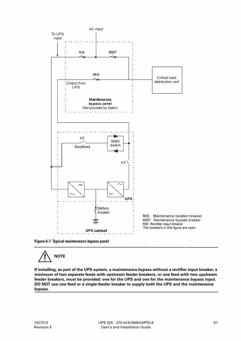
Figure 6-7. Typical maintenance bypass panel
NOTE
If installing, as part of the UPS system, a maintenance bypass without a rectifier input breaker, a
minimum of two separate feeds with upstream feeder breakers, or one feed with two upstream
feeder breakers, must be provided: one for the UPS and one for the maintenance bypass input.
DO NOT use one feed or a single-feeder breaker to supply both the UPS and the maintenance
bypass.
1027212 UPS 225 - 275 kVA/300kVAPF0.8 61Revision E User’s and Installation Guide
6.4 Multiple UPS distributed bypass system
Distributed bypass parallel operation extends the normal operation of Eaton 9395 UPSs by offering increased capacity and/or redundant capability.
The output of the system is normally supplied by Uninterruptible Power Modules (UPMs) contained in each UPS. Multiple UPMs are connected with their outputs in parallel (tied together) to provide a load level greater than the rating of one UPM, for redundancy, or both. The paralleled UPMs supply the output load with protected power as long as the load does not exceed the combined rating of the paralleled UPMs.
The power system is redundant as long as one of the UPMs can be disconnected from the output bus and the remaining UPMs can continue to supply power to the load without exceeding their ratings.
When the load is being supplied by the UPMs, the system output bus is continuously monitored for an overvoltage or undervoltage condition. If an out of limits condition is detected, the paralleled UPSs transfer the load to bypass using the UPS static switches.
Communication is required between the UPSs for system metering and mode control. System level communication and control are accomplished using a Controller Area Network (CAN). A pull chain signal in each UPS, connected to the other UPSs in parallel and tied to the bypass Status Relay in each UPS, is used for a secondary communication path. This arrangement ensures bypass control even if the CAN bus is lost.
The system is paralleled for (N+1) redundancy, as long as there is always one or more UPMs online than required to support the load. The system is paralleled for capacity if all UPMs in a system are required to support the load.
6.4.1 Multiple UPS parallel system modes
Similar to the single UPS system, the Eaton 9395 UPS parallel system supports a critical load in five different modes of operation. The standard operation modes are:
NOTE
The Variable Module Management System and Energy Saver System modes are mutually
exclusive.
• In Normal mode, the paralleled UPMs supply the critical load with clean, filtered power. Each UPM battery charger also provides charging current for the battery if needed.
• In Energy Saver System (ESS) mode, commercial AC power is supplied directly to the critical load through the continuous static switch and transfers automatically to Normal mode if an abnormal condition is detected. ESS mode in a parallel system operates the same as it does in a single UPS system (see Section 6.2.5).
• In Variable Module Management System (VMMS) mode, the UPS operates as a traditional double-conversion UPS, but selectively shifts the load to fewer UPMs to increase the efficiency of the UPS. VMMS mode operates the same as it does in a single UPS system (see Section 6.2.4).
• In Bypass mode, the critical load is directly supported by utility power through the bypass circuits in each UPS.
• In Battery mode, the battery provides DC power, which maintains UPM operation. The UPM batteries support the critical load.
62 UPS 225 - 275 kVA/300kVAPF0.8 1027212User’s and Installation Guide Revision E
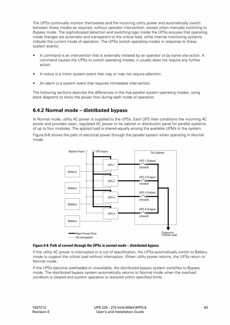
The UPSs continually monitor themselves and the incoming utility power and automatically switch between these modes as required, without operator intervention, except when manually switching to Bypass mode. The sophisticated detection and switching logic inside the UPSs ensures that operating mode changes are automatic and transparent to the critical load, while internal monitoring systems indicate the current mode of operation. The UPSs switch operating modes in response to these system events:
• A command is an intervention that is externally initiated by an operator or by some site action. A command causes the UPSs to switch operating modes; it usually does not require any further action.
• A notice is a minor system event that may or may not require attention.
• An alarm is a system event that requires immediate intervention.
The following sections describe the differences in the five parallel system operating modes, using block diagrams to show the power flow during each mode of operation.
6.4.2 Normal mode – distributed bypass
In Normal mode, utility AC power is supplied to the UPSs. Each UPS then conditions the incoming AC power and provides clean, regulated AC power to tie cabinet or distribution panel for parallel systems of up to four modules. The applied load is shared equally among the available UPMs in the system.
Figure 6-8 shows the path of electrical power through the parallel system when operating in Normal mode.
Figure 6-8. Path of current through the UPSs in normal mode – distributed bypass
If the utility AC power is interrupted or is out of specification, the UPSs automatically switch to Battery mode to support the critical load without interruption. When utility power returns, the UPSs return to Normal mode.
If the UPSs become overloaded or unavailable, the distributed bypass system switches to Bypass mode. The distributed bypass system automatically returns to Normal mode when the overload condition is cleared and system operation is restored within specified limits.
Main Power Flow Output to Critical Load
UPS Input Tie Cabinet
UPS 1 Output
(closed)
(closed)
(closed)
(closed)
Bypass Input
UPS 2 Output
UPS 3 Output
UPS 4 Output
De-energized
Battery
Battery
Battery
Battery
UPS 1
UPS 2
UPS 3
UPS 4
1027212 UPS 225 - 275 kVA/300kVAPF0.8 63Revision E User’s and Installation Guide
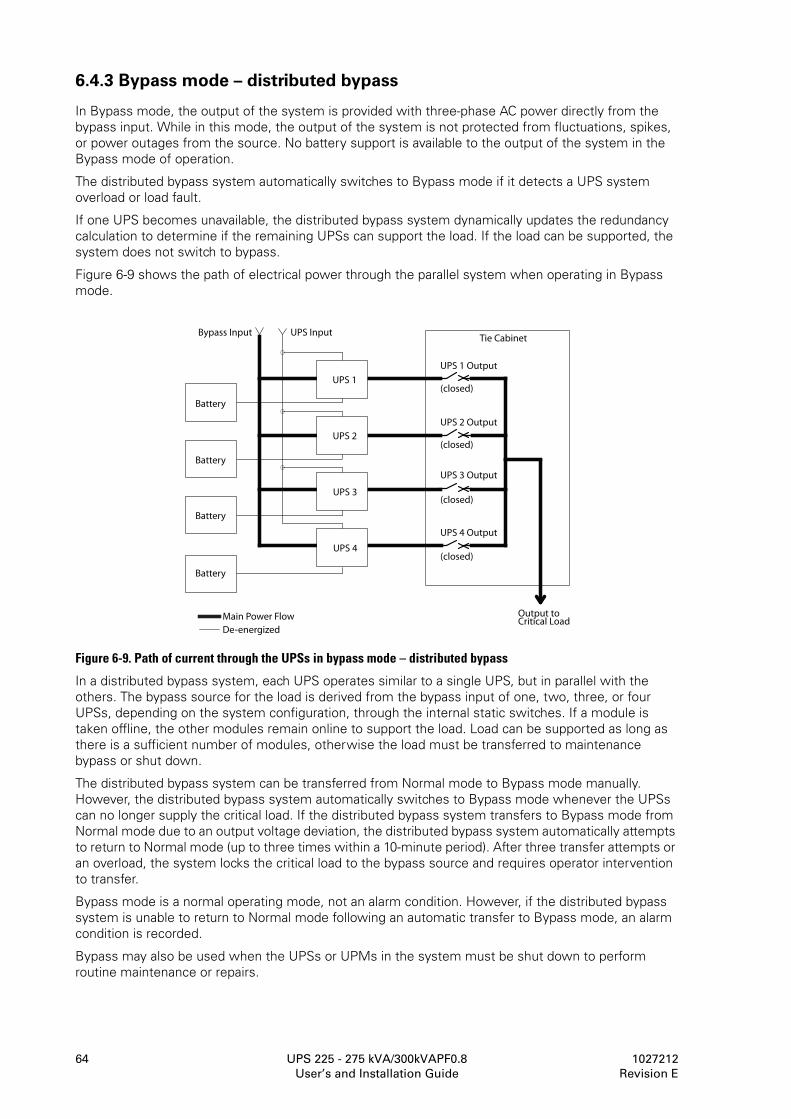
6.4.3 Bypass mode – distributed bypass
In Bypass mode, the output of the system is provided with three-phase AC power directly from the bypass input. While in this mode, the output of the system is not protected from fluctuations, spikes, or power outages from the source. No battery support is available to the output of the system in the Bypass mode of operation.
The distributed bypass system automatically switches to Bypass mode if it detects a UPS system overload or load fault.
If one UPS becomes unavailable, the distributed bypass system dynamically updates the redundancy calculation to determine if the remaining UPSs can support the load. If the load can be supported, the system does not switch to bypass.
Figure 6-9 shows the path of electrical power through the parallel system when operating in Bypass mode.
Figure 6-9. Path of current through the UPSs in bypass mode – distributed bypass
In a distributed bypass system, each UPS operates similar to a single UPS, but in parallel with the others. The bypass source for the load is derived from the bypass input of one, two, three, or four UPSs, depending on the system configuration, through the internal static switches. If a module is taken offline, the other modules remain online to support the load. Load can be supported as long as there is a sufficient number of modules, otherwise the load must be transferred to maintenance bypass or shut down.
The distributed bypass system can be transferred from Normal mode to Bypass mode manually. However, the distributed bypass system automatically switches to Bypass mode whenever the UPSs can no longer supply the critical load. If the distributed bypass system transfers to Bypass mode from Normal mode due to an output voltage deviation, the distributed bypass system automatically attempts to return to Normal mode (up to three times within a 10-minute period). After three transfer attempts or an overload, the system locks the critical load to the bypass source and requires operator intervention to transfer.
Bypass mode is a normal operating mode, not an alarm condition. However, if the distributed bypass system is unable to return to Normal mode following an automatic transfer to Bypass mode, an alarm condition is recorded.
Bypass may also be used when the UPSs or UPMs in the system must be shut down to perform routine maintenance or repairs.
Main Power Flow Output to Critical Load
UPS Input Tie Cabinet
UPS 1 Output
(closed)
(closed)
(closed)
(closed)
Bypass Input
UPS 2 Output
UPS 3 Output
UPS 4 Output
De-energized
Battery
Battery
Battery
Battery
UPS 1
UPS 2
UPS 3
UPS 4
64 UPS 225 - 275 kVA/300kVAPF0.8 1027212User’s and Installation Guide Revision E
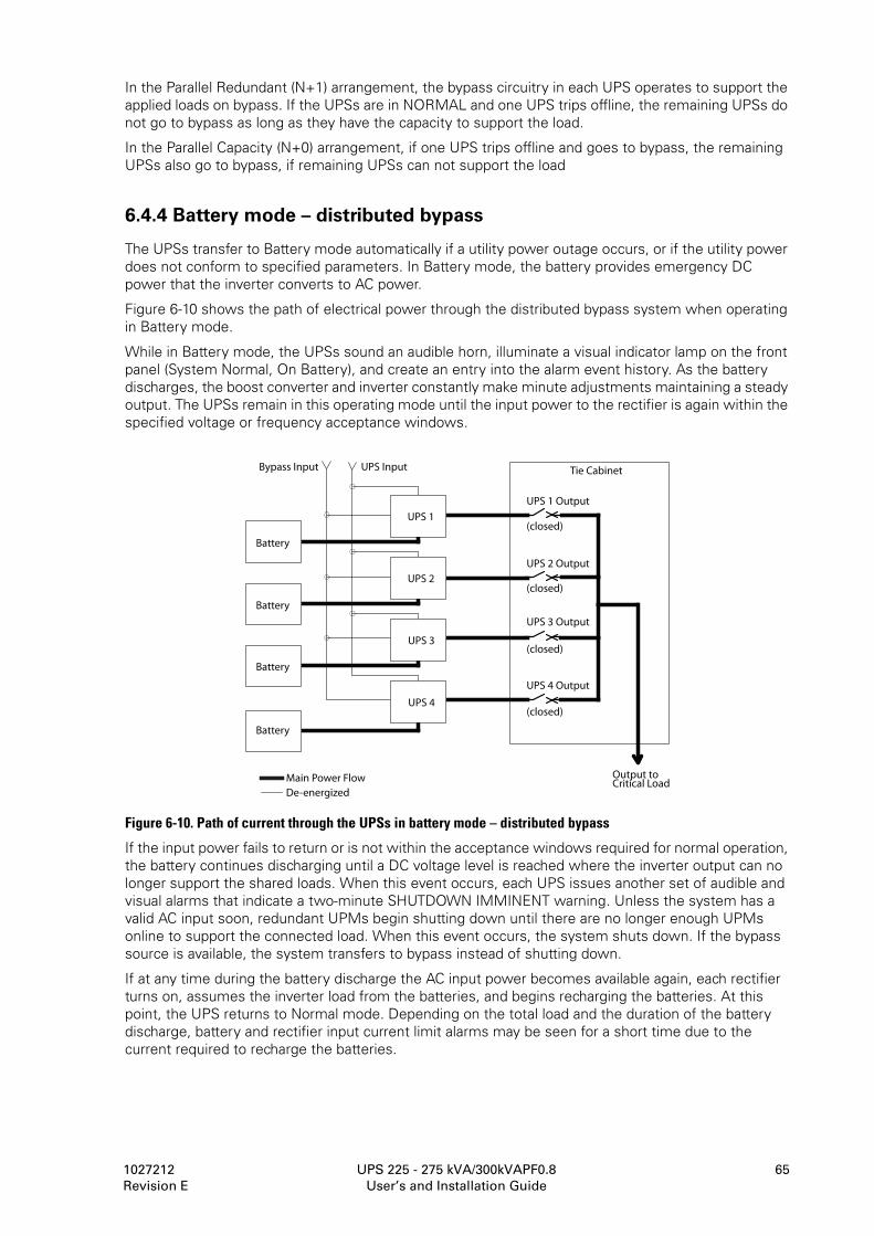
In the Parallel Redundant (N+1) arrangement, the bypass circuitry in each UPS operates to support the applied loads on bypass. If the UPSs are in NORMAL and one UPS trips offline, the remaining UPSs do not go to bypass as long as they have the capacity to support the load.
In the Parallel Capacity (N+0) arrangement, if one UPS trips offline and goes to bypass, the remaining UPSs also go to bypass, if remaining UPSs can not support the load
6.4.4 Battery mode – distributed bypass
The UPSs transfer to Battery mode automatically if a utility power outage occurs, or if the utility power does not conform to specified parameters. In Battery mode, the battery provides emergency DC power that the inverter converts to AC power.
Figure 6-10 shows the path of electrical power through the distributed bypass system when operating in Battery mode.
While in Battery mode, the UPSs sound an audible horn, illuminate a visual indicator lamp on the front panel (System Normal, On Battery), and create an entry into the alarm event history. As the battery discharges, the boost converter and inverter constantly make minute adjustments maintaining a steady output. The UPSs remain in this operating mode until the input power to the rectifier is again within the specified voltage or frequency acceptance windows.
Figure 6-10. Path of current through the UPSs in battery mode – distributed bypass
If the input power fails to return or is not within the acceptance windows required for normal operation, the battery continues discharging until a DC voltage level is reached where the inverter output can no longer support the shared loads. When this event occurs, each UPS issues another set of audible and visual alarms that indicate a two-minute SHUTDOWN IMMINENT warning. Unless the system has a valid AC input soon, redundant UPMs begin shutting down until there are no longer enough UPMs online to support the connected load. When this event occurs, the system shuts down. If the bypass source is available, the system transfers to bypass instead of shutting down.
If at any time during the battery discharge the AC input power becomes available again, each rectifier turns on, assumes the inverter load from the batteries, and begins recharging the batteries. At this point, the UPS returns to Normal mode. Depending on the total load and the duration of the battery discharge, battery and rectifier input current limit alarms may be seen for a short time due to the current required to recharge the batteries.
Main Power Flow Output to Critical Load
UPS Input Tie Cabinet
UPS 1 Output
(closed)
(closed)
(closed)
(closed)
Bypass Input
UPS 2 Output
UPS 3 Output
UPS 4 Output
De-energized
Battery
Battery
Battery
Battery
UPS 1
UPS 2
UPS 3
UPS 4
1027212 UPS 225 - 275 kVA/300kVAPF0.8 65Revision E User’s and Installation Guide
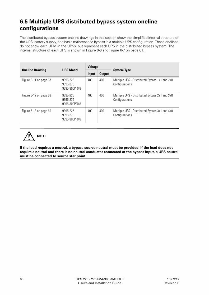
6.5 Multiple UPS distributed bypass system oneline
configurations
The distributed bypass system oneline drawings in this section show the simplified internal structure of the UPS, battery supply, and basic maintenance bypass in a multiple UPS configuration. These onelines do not show each UPM in the UPSs, but represent each UPS in the distributed bypass system. The internal structure of each UPS is shown in Figure 6-6 and Figure 6-7 on page 61.
NOTE
If the load requires a neutral, a bypass source neutral must be provided. If the load does not
require a neutral and there is no neutral conductor connected at the bypass input, a UPS neutral
must be connected to source star point.
Oneline Drawing UPS ModelVoltage
System TypeInput Output
Figure 6-11 on page 67 9395-2259395-2759395-300PF0.8
400 400 Multiple UPS - Distributed Bypass 1+1 and 2+0 Configurations
Figure 6-12 on page 68 9395-2259395-2759395-300PF0.8
400 400 Multiple UPS - Distributed Bypass 2+1 and 3+0 Configurations
Figure 6-13 on page 69 9395-2259395-2759395-300PF0.8
400 400 Multiple UPS - Distributed Bypass 3+1 and 4+0 Configurations
66 UPS 225 - 275 kVA/300kVAPF0.8 1027212User’s and Installation Guide Revision E
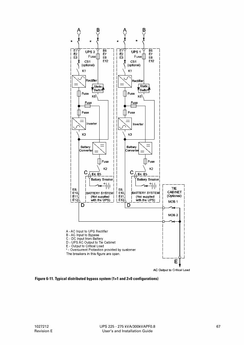
Figure 6-11. Typical distributed bypass system (1+1 and 2+0 configurations)
1027212 UPS 225 - 275 kVA/300kVAPF0.8 67Revision E User’s and Installation Guide
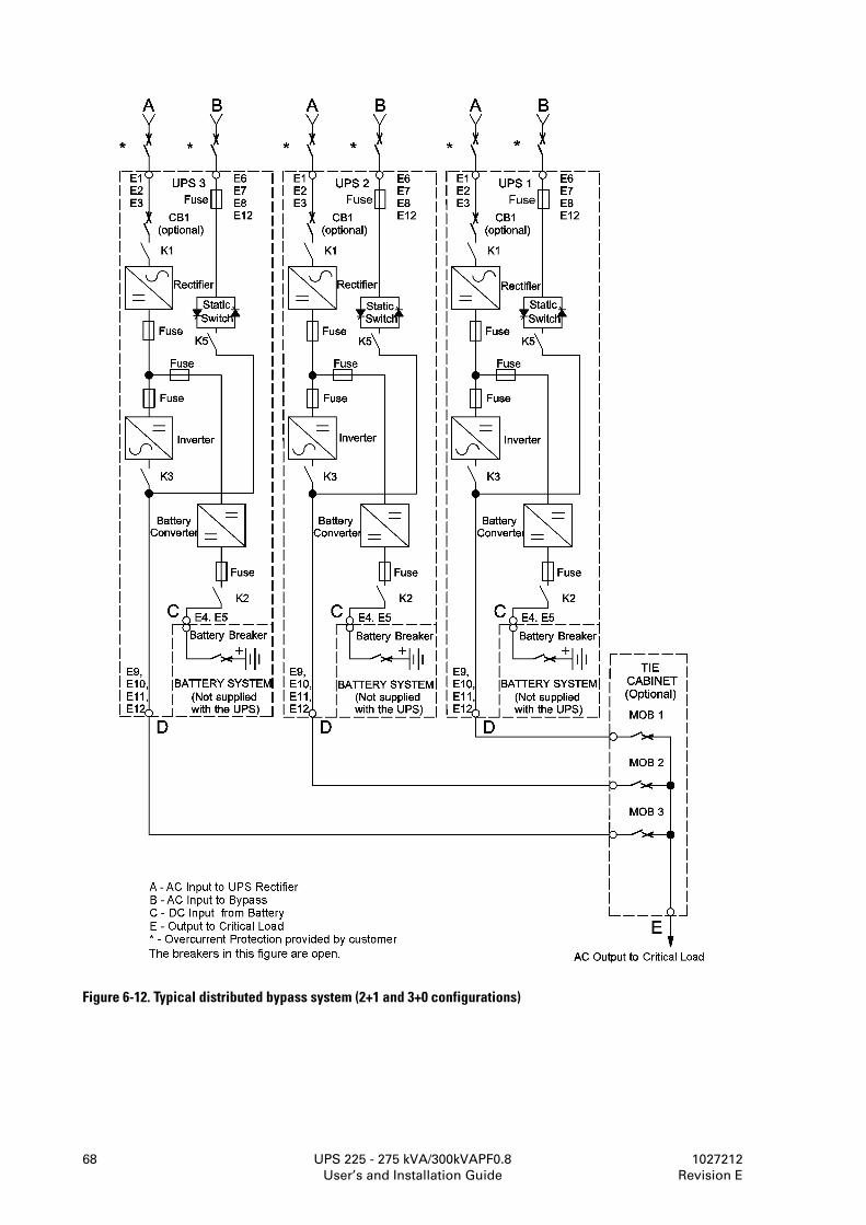
Figure 6-12. Typical distributed bypass system (2+1 and 3+0 configurations)
68 UPS 225 - 275 kVA/300kVAPF0.8 1027212User’s and Installation Guide Revision E
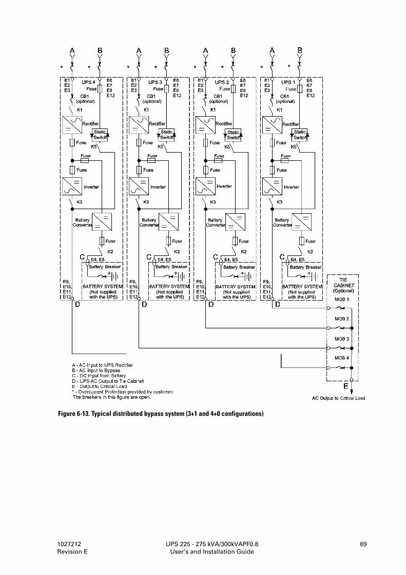
Figure 6-13. Typical distributed bypass system (3+1 and 4+0 configurations)
1027212 UPS 225 - 275 kVA/300kVAPF0.8 69Revision E User’s and Installation Guide
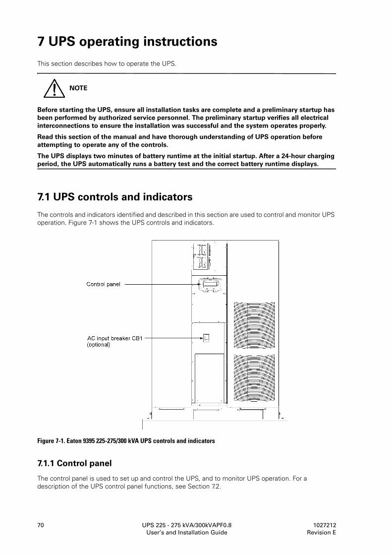
7 UPS operating instructions
This section describes how to operate the UPS.
NOTE
Before starting the UPS, ensure all installation tasks are complete and a preliminary startup has
been performed by authorized service personnel. The preliminary startup verifies all electrical
interconnections to ensure the installation was successful and the system operates properly.
Read this section of the manual and have thorough understanding of UPS operation before
attempting to operate any of the controls.
The UPS displays two minutes of battery runtime at the initial startup. After a 24-hour charging
period, the UPS automatically runs a battery test and the correct battery runtime displays.
7.1 UPS controls and indicators
The controls and indicators identified and described in this section are used to control and monitor UPS operation. Figure 7-1 shows the UPS controls and indicators.
Figure 7-1. Eaton 9395 225-275/300 kVA UPS controls and indicators
7.1.1 Control panel
The control panel is used to set up and control the UPS, and to monitor UPS operation. For a description of the UPS control panel functions, see Section 7.2.
70 UPS 225 - 275 kVA/300kVAPF0.8 1027212User’s and Installation Guide Revision E
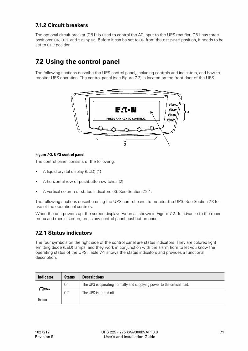
7.1.2 Circuit breakers
The optional circuit breaker (CB1) is used to control the AC input to the UPS rectifier. CB1 has three positions: ON, OFF and tripped. Before it can be set to ON from the tripped position, it needs to be set to OFF position.
7.2 Using the control panel
The following sections describe the UPS control panel, including controls and indicators, and how to monitor UPS operation. The control panel (see Figure 7-2) is located on the front door of the UPS.
Figure 7-2. UPS control panel
The control panel consists of the following:
• A liquid crystal display (LCD) (1)
• A horizontal row of pushbutton switches (2)
• A vertical column of status indicators (3). See Section 7.2.1.
The following sections describe using the UPS control panel to monitor the UPS. See Section 7.3 for use of the operational controls.
When the unit powers up, the screen displays Eaton as shown in Figure 7-2. To advance to the main menu and mimic screen, press any control panel pushbutton once.
7.2.1 Status indicators
The four symbols on the right side of the control panel are status indicators. They are colored light emitting diode (LED) lamps, and they work in conjunction with the alarm horn to let you know the operating status of the UPS. Table 7-1 shows the status indicators and provides a functional description.
Indicator Status Descriptions
Green
On The UPS is operating normally and supplying power to the critical load.
Off The UPS is turned off.
1027212 UPS 225 - 275 kVA/300kVAPF0.8 71Revision E User’s and Installation Guide
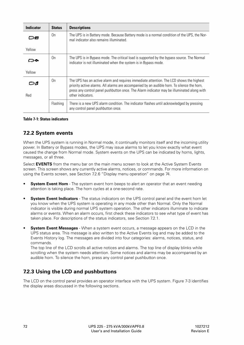
Table 7-1: Status indicators
7.2.2 System events
When the UPS system is running in Normal mode, it continually monitors itself and the incoming utility power. In Battery or Bypass modes, the UPS may issue alarms to let you know exactly what event caused the change from Normal mode. System events on the UPS can be indicated by horns, lights, messages, or all three.
Select EVENTS from the menu bar on the main menu screen to look at the Active System Events screen. This screen shows any currently active alarms, notices, or commands. For more information on using the Events screen, see Section 7.2.6 “Display menu operation” on page 74.
• System Event Horn - The system event horn beeps to alert an operator that an event needing attention is taking place. The horn cycles at a one-second rate.
• System Event Indicators - The status indicators on the UPS control panel and the event horn let you know when the UPS system is operating in any mode other than Normal. Only the Normal indicator is visible during normal UPS system operation. The other indicators illuminate to indicate alarms or events. When an alarm occurs, first check these indicators to see what type of event has taken place. For descriptions of the status indicators, see Section 7.2.1.
• System Event Messages - When a system event occurs, a message appears on the LCD in the UPS status area. This message is also written to the Active Events log and may be added to the Events History log. The messages are divided into four categories: alarms, notices, status, and commands.The top line of the LCD scrolls all active notices and alarms. The top line of display blinks while scrolling when the system needs attention. Some notices and alarms may be accompanied by an audible horn. To silence the horn, press any control panel pushbutton once.
7.2.3 Using the LCD and pushbuttons
The LCD on the control panel provides an operator interface with the UPS system. Figure 7-3 identifies the display areas discussed in the following sections.
Yellow
On The UPS is in Battery mode. Because Battery mode is a normal condition of the UPS, the Nor-mal indicator also remains illuminated.
Yellow
On The UPS is in Bypass mode. The critical load is supported by the bypass source. The Normal indicator is not illuminated when the system is in Bypass mode.
Red
On The UPS has an active alarm and requires immediate attention. The LCD shows the highest priority active alarms. All alarms are accompanied by an audible horn. To silence the horn, press any control panel pushbutton once. The Alarm indicator may be illuminated along with other indicators.
Flashing There is a new UPS alarm condition. The indicator flashes until acknowledged by pressing any control panel pushbutton once.
Indicator Status Descriptions
72 UPS 225 - 275 kVA/300kVAPF0.8 1027212User’s and Installation Guide Revision E
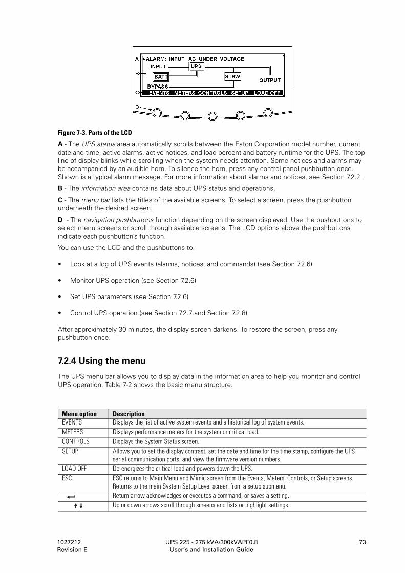
Figure 7-3. Parts of the LCD
A - The UPS status area automatically scrolls between the Eaton Corporation model number, current date and time, active alarms, active notices, and load percent and battery runtime for the UPS. The top line of display blinks while scrolling when the system needs attention. Some notices and alarms may be accompanied by an audible horn. To silence the horn, press any control panel pushbutton once. Shown is a typical alarm message. For more information about alarms and notices, see Section 7.2.2.
B - The information area contains data about UPS status and operations.
C - The menu bar lists the titles of the available screens. To select a screen, press the pushbutton underneath the desired screen.
D - The navigation pushbuttons function depending on the screen displayed. Use the pushbuttons to select menu screens or scroll through available screens. The LCD options above the pushbuttons indicate each pushbutton’s function.
You can use the LCD and the pushbuttons to:
• Look at a log of UPS events (alarms, notices, and commands) (see Section 7.2.6)
• Monitor UPS operation (see Section 7.2.6)
• Set UPS parameters (see Section 7.2.6)
• Control UPS operation (see Section 7.2.7 and Section 7.2.8)
After approximately 30 minutes, the display screen darkens. To restore the screen, press any pushbutton once.
7.2.4 Using the menu
The UPS menu bar allows you to display data in the information area to help you monitor and control UPS operation. Table 7-2 shows the basic menu structure.
Menu option DescriptionEVENTS Displays the list of active system events and a historical log of system events.METERS Displays performance meters for the system or critical load.CONTROLS Displays the System Status screen.SETUP Allows you to set the display contrast, set the date and time for the time stamp, configure the UPS
serial communication ports, and view the firmware version numbers.LOAD OFF De-energizes the critical load and powers down the UPS.ESC ESC returns to Main Menu and Mimic screen from the Events, Meters, Controls, or Setup screens.
Returns to the main System Setup Level screen from a setup submenu.Return arrow acknowledges or executes a command, or saves a setting.Up or down arrows scroll through screens and lists or highlight settings.
1027212 UPS 225 - 275 kVA/300kVAPF0.8 73Revision E User’s and Installation Guide
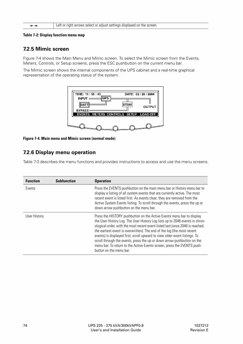
Table 7-2: Display function menu map
7.2.5 Mimic screen
Figure 7-4 shows the Main Menu and Mimic screen. To select the Mimic screen from the Events, Meters, Controls, or Setup screens, press the ESC pushbutton on the current menu bar.
The Mimic screen shows the internal components of the UPS cabinet and a real-time graphical representation of the operating status of the system.
Figure 7-4. Main menu and Mimic screen (normal mode)
7.2.6 Display menu operation
Table 7-3 describes the menu functions and provides instructions to access and use the menu screens.
Left or right arrows select or adjust settings displayed on the screen.
Function Subfunction Operation
Events Press the EVENTS pushbutton on the main menu bar or History menu bar to display a listing of all system events that are currently active. The most recent event is listed first. As events clear, they are removed from the Active System Events listing. To scroll through the events, press the up or down arrow pushbutton on the menu bar.
User History Press the HISTORY pushbutton on the Active Events menu bar to display the User History Log. The User History Log lists up to 2048 events in chron-ological order, with the most recent event listed last (once 2048 is reached, the earliest event is overwritten). The end of the log (the most recent events) is displayed first; scroll upward to view older event listings. To scroll through the events, press the up or down arrow pushbutton on the menu bar. To return to the Active Events screen, press the EVENTS push-button on the menu bar.
74 UPS 225 - 275 kVA/300kVAPF0.8 1027212User’s and Installation Guide Revision E
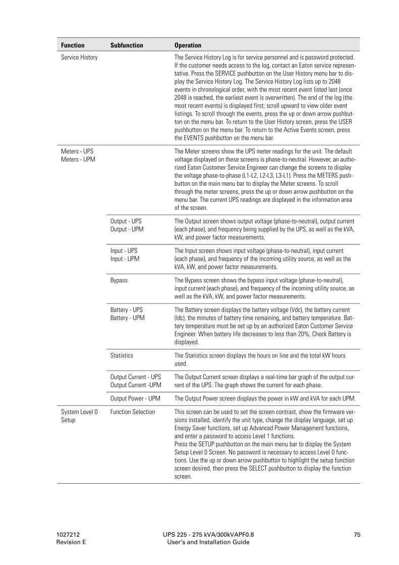
Service History The Service History Log is for service personnel and is password protected. If the customer needs access to the log, contact an Eaton service represen-tative. Press the SERVICE pushbutton on the User History menu bar to dis-play the Service History Log. The Service History Log lists up to 2048 events in chronological order, with the most recent event listed last (once 2048 is reached, the earliest event is overwritten). The end of the log (the most recent events) is displayed first; scroll upward to view older event listings. To scroll through the events, press the up or down arrow pushbut-ton on the menu bar. To return to the User History screen, press the USER pushbutton on the menu bar. To return to the Active Events screen, press the EVENTS pushbutton on the menu bar.
Meters - UPSMeters - UPM
The Meter screens show the UPS meter readings for the unit. The default voltage displayed on these screens is phase-to-neutral. However, an autho-rized Eaton Customer Service Engineer can change the screens to display the voltage phase-to-phase (L1-L2, L2-L3, L3-L1). Press the METERS push-button on the main menu bar to display the Meter screens. To scroll through the meter screens, press the up or down arrow pushbutton on the menu bar. The current UPS readings are displayed in the information area of the screen.
Output - UPSOutput - UPM
The Output screen shows output voltage (phase-to-neutral), output current (each phase), and frequency being supplied by the UPS, as well as the kVA, kW, and power factor measurements.
Input - UPSInput - UPM
The Input screen shows input voltage (phase-to-neutral), input current (each phase), and frequency of the incoming utility source, as well as the kVA, kW, and power factor measurements.
Bypass The Bypass screen shows the bypass input voltage (phase-to-neutral), input current (each phase), and frequency of the incoming utility source, as well as the kVA, kW, and power factor measurements.
Battery - UPSBattery - UPM
The Battery screen displays the battery voltage (Vdc), the battery current (Idc), the minutes of battery time remaining, and battery temperature. Bat-tery temperature must be set up by an authorized Eaton Customer Service Engineer. When battery life decreases to less than 20%, Check Battery is displayed.
Statistics The Statistics screen displays the hours on line and the total kW hours used.
Output Current - UPSOutput Current -UPM
The Output Current screen displays a real-time bar graph of the output cur-rent of the UPS. The graph shows the current for each phase.
Output Power - UPM The Output Power screen displays the power in kW and kVA for each UPM.
System Level 0 Setup
Function Selection This screen can be used to set the screen contrast, show the firmware ver-sions installed, identify the unit type, change the display language, set up Energy Saver functions, set up Advanced Power Management functions, and enter a password to access Level 1 functions.Press the SETUP pushbutton on the main menu bar to display the System Setup Level 0 Screen. No password is necessary to access Level 0 func-tions. Use the up or down arrow pushbutton to highlight the setup function screen desired, then press the SELECT pushbutton to display the function screen.
Function Subfunction Operation
1027212 UPS 225 - 275 kVA/300kVAPF0.8 75Revision E User’s and Installation Guide
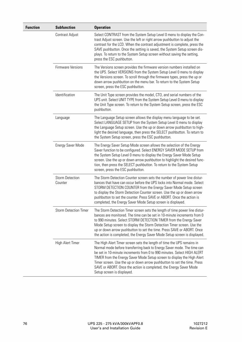
Contrast Adjust Select CONTRAST from the System Setup Level 0 menu to display the Con-trast Adjust screen. Use the left or right arrow pushbutton to adjust the contrast for the LCD. When the contrast adjustment is complete, press the SAVE pushbutton. Once the setting is saved, the System Setup screen dis-plays. To return to the System Setup screen without saving the setting, press the ESC pushbutton.
Firmware Versions The Versions screen provides the firmware version numbers installed on the UPS. Select VERSIONS from the System Setup Level 0 menu to display the Versions screen. To scroll through the firmware types, press the up or down arrow pushbutton on the menu bar. To return to the System Setup screen, press the ESC pushbutton.
Identification The Unit Type screen provides the model, CTO, and serial numbers of the UPS unit. Select UNIT TYPE from the System Setup Level 0 menu to display the Unit Type screen. To return to the System Setup screen, press the ESC pushbutton.
Language The Language Setup screen allows the display menu language to be set. Select LANGUAGE SETUP from the System Setup Level 0 menu to display the Language Setup screen. Use the up or down arrow pushbutton to high-light the desired language, then press the SELECT pushbutton. To return to the System Setup screen, press the ESC pushbutton.
Energy Saver Mode The Energy Saver Setup Mode screen allows the selection of the Energy Saver function to be configured. Select ENERGY SAVER MODE SETUP from the System Setup Level 0 menu to display the Energy Saver Mode Setup screen. Use the up or down arrow pushbutton to highlight the desired func-tion, then press the SELECT pushbutton. To return to the System Setup screen, press the ESC pushbutton.
Storm DetectionCounter
The Storm Detection Counter screen sets the number of power line distur-bances that have can occur before the UPS locks into Normal mode. Select STORM DETECTION COUNTER from the Energy Saver Mode Setup screen to display the Storm Detection Counter screen. Use the up or down arrow pushbutton to set the counter. Press SAVE or ABORT. Once the action is completed, the Energy Saver Mode Setup screen is displayed.
Storm Detection Timer The Storm Detection Timer screen sets the length of time power line distur-bances are monitored. The time can be set in 10-minute increments from 0 to 990 minutes. Select STORM DETECTION TIMER from the Energy Saver Mode Setup screen to display the Storm Detection Timer screen. Use the up or down arrow pushbutton to set the time. Press SAVE or ABORT. Once the action is completed, the Energy Saver Mode Setup screen is displayed.
High Alert Timer The High Alert Timer screen sets the length of time the UPS remains in Normal mode before transferring back to Energy Saver mode. The time can be set in 10-minute increments from 0 to 990 minutes. Select HIGH ALERT TIMER from the Energy Saver Mode Setup screen to display the High Alert Timer screen. Use the up or down arrow pushbutton to set the time. Press SAVE or ABORT. Once the action is completed, the Energy Saver Mode Setup screen is displayed.
Function Subfunction Operation
76 UPS 225 - 275 kVA/300kVAPF0.8 1027212User’s and Installation Guide Revision E
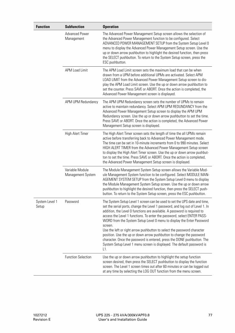
Advanced PowerManagement
The Advanced Power Management Setup screen allows the selection of the Advanced Power Management function to be configured. Select ADVANCED POWER MANAGEMENT SETUP from the System Setup Level 0 menu to display the Advanced Power Management Setup screen. Use the up or down arrow pushbutton to highlight the desired function, then press the SELECT pushbutton. To return to the System Setup screen, press the ESC pushbutton.
APM Load Limit The APM Load Limit screen sets the maximum load that can be when drawn from a UPM before additional UPMs are activated. Select APM LOAD LIMIT from the Advanced Power Management Setup screen to dis-play the APM Load Limit screen. Use the up or down arrow pushbutton to set the counter. Press SAVE or ABORT. Once the action is completed, the Advanced Power Management screen is displayed.
APM UPM Redundancy The APM UPM Redundancy screen sets the number of UPMs to remain active to maintain redundancy. Select APM UPM REDUNDANCY from the Advanced Power Management Setup screen to display the APM UPM Redundancy screen. Use the up or down arrow pushbutton to set the time. Press SAVE or ABORT. Once the action is completed, the Advanced Power Management Setup screen is displayed.
High Alert Timer The High Alert Timer screen sets the length of time the all UPMs remain active before transferring back to Advanced Power Management mode. The time can be set in 10-minute increments from 0 to 990 minutes. Select HIGH ALERT TIMER from the Advanced Power Management Setup screen to display the High Alert Timer screen. Use the up or down arrow pushbut-ton to set the time. Press SAVE or ABORT. Once the action is completed, the Advanced Power Management Setup screen is displayed.
Variable ModuleManagement System
The Module Management System Setup screen allows the Variable Mod-ule Management System function to be configured. Select MODULE MAN-AGEMENT SYSTEM SETUP from the System Setup Level 0 menu to display the Module Management System Setup screen. Use the up or down arrow pushbutton to highlight the desired function, then press the SELECT push-button. To return to the System Setup screen, press the ESC pushbutton.
System Level 1 Setup
Password The System Setup Level 1 screen can be used to set the UPS date and time, set the serial ports, change the Level 1 password, and log out of Level 1. In addition, the Level 0 functions are available. A password is required to access the Level 1 functions. To enter the password, select ENTER PASS-WORD from the System Setup Level 0 menu to display the Enter Password screen.Use the left or right arrow pushbutton to select the password character position. Use the up or down arrow pushbutton to change the password character. Once the password is entered, press the DONE pushbutton. The System Setup Level 1 menu screen is displayed. The default password is L1.
Function Selection Use the up or down arrow pushbutton to highlight the setup function screen desired, then press the SELECT pushbutton to display the function screen. The Level 1 screen times out after 60 minutes or can be logged out at any time by selecting the LOG OUT function from the menu screen.
Function Subfunction Operation
1027212 UPS 225 - 275 kVA/300kVAPF0.8 77Revision E User’s and Installation Guide
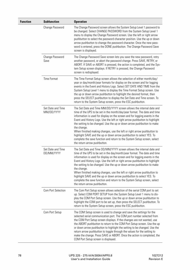
Change Password The Change Password screen allows the System Setup Level 1 password to be changed. Select CHANGE PASSWORD from the System Setup Level 1 menu to display the Change Password screen. Use the left or right arrow pushbutton to select the password character position. Use the up or down arrow pushbutton to change the password character. Once the new pass-word is entered, press the DONE pushbutton. The Change Password Save screen is displayed.
Change Password Save
The Change Password Save screen lets you save the new password, retry another password, or abort the password change. Press SAVE, RETRY, or ABORT. If SAVE or ABORT is pressed, the action is completed, and the Sys-tem Setup screen displays. If RETRY is pressed, the Change Password screen is redisplayed.
Time Format The Time Format Setup screen allows the selection of either month/day/year or day/month/year formats for display on the screen and for logging events in the Event and History Logs. Select SET DATE AND TIME from the System Setup Level 1 menu to display the Time Format Setup screen. Use the up or down arrow pushbutton to highlight the desired format, then press the SELECT pushbutton to display the Set Date and Time screen. To return to the System Setup screen, press the ESC pushbutton.
Set Date and Time MM/DD/YYYY
The Set Date and Time MM/DD/YYYY screen allows the internal date and time of the UPS to be set in the month/day/year format. The date and time information is used for display on the screen and for logging events in the Event and History Logs. Use the left or right arrow pushbutton to highlight the setting to be changed. Use the up or down arrow pushbutton to make the change.When finished making changes, use the left or right arrow pushbutton to highlight SAVE and the up or down arrow pushbutton to select YES. To complete the save function and return to the System Setup screen, select the return arrow pushbutton.
Set Date and TimeDD/MM/YYYY
The Set Date and Time DD/MM/YYYY screen allows the internal date and time of the UPS to be set in the day/month/year format. The date and time information is used for display on the screen and for logging events in the Event and History Logs. Use the left or right arrow pushbutton to highlight the setting to be changed. Use the up or down arrow pushbutton to make the change.When finished making changes, use the left or right arrow pushbutton to highlight SAVE and the up or down arrow pushbutton to select YES. To complete the save function and return to the System Setup screen, select the return arrow pushbutton.
Com Port Selection The Com Port Setup screen allows selection of the serial COM port to set up. Select COM PORT SETUP from the System Setup Level 1 menu to dis-play the COM Port Setup screen. Use the up or down arrow pushbutton to highlight the COM port to be set up, then press the SELECT pushbutton. To return to the System Setup screen, press the ESC pushbutton.
Com Port Setup The COM Setup screen is used to change and save the settings for the selected serial communication port. The COM port number selected from the COM Port Setup screen displays. If the changes are not wanted, use the ABORT pushbutton to return to the COM Port Setup screen. Use the up or down arrow pushbutton to highlight the setting to be changed. Use the return arrow pushbutton to toggle through the values for the setting to make the change. Press SAVE or ABORT. Once the action is completed, the COM Port Setup screen is displayed.
Function Subfunction Operation
78 UPS 225 - 275 kVA/300kVAPF0.8 1027212User’s and Installation Guide Revision E
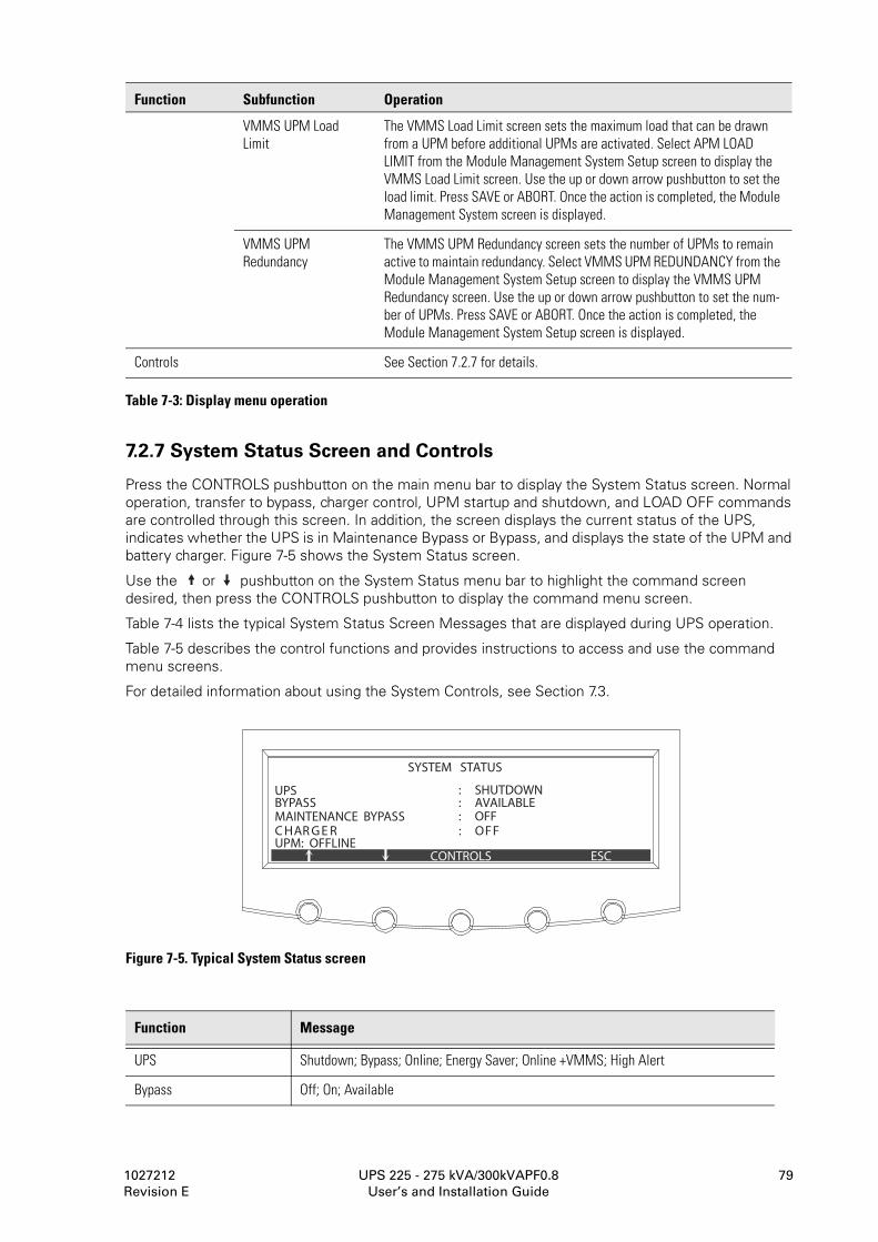
Table 7-3: Display menu operation
7.2.7 System Status Screen and Controls
Press the CONTROLS pushbutton on the main menu bar to display the System Status screen. Normal operation, transfer to bypass, charger control, UPM startup and shutdown, and LOAD OFF commands are controlled through this screen. In addition, the screen displays the current status of the UPS, indicates whether the UPS is in Maintenance Bypass or Bypass, and displays the state of the UPM and battery charger. Figure 7-5 shows the System Status screen.
Use the or pushbutton on the System Status menu bar to highlight the command screen desired, then press the CONTROLS pushbutton to display the command menu screen.
Table 7-4 lists the typical System Status Screen Messages that are displayed during UPS operation.
Table 7-5 describes the control functions and provides instructions to access and use the command menu screens.
For detailed information about using the System Controls, see Section 7.3.
Figure 7-5. Typical System Status screen
VMMS UPM Load Limit
The VMMS Load Limit screen sets the maximum load that can be drawn from a UPM before additional UPMs are activated. Select APM LOAD LIMIT from the Module Management System Setup screen to display the VMMS Load Limit screen. Use the up or down arrow pushbutton to set the load limit. Press SAVE or ABORT. Once the action is completed, the Module Management System screen is displayed.
VMMS UPMRedundancy
The VMMS UPM Redundancy screen sets the number of UPMs to remain active to maintain redundancy. Select VMMS UPM REDUNDANCY from the Module Management System Setup screen to display the VMMS UPM Redundancy screen. Use the up or down arrow pushbutton to set the num-ber of UPMs. Press SAVE or ABORT. Once the action is completed, the Module Management System Setup screen is displayed.
Controls See Section 7.2.7 for details.
Function Message
UPS Shutdown; Bypass; Online; Energy Saver; Online +VMMS; High Alert
Bypass Off; On; Available
Function Subfunction Operation
MAINTENANCE BYPASSBYPASS
UPM: OFFLINE
SHUTDOWN:AVAILABLE:OFF:
SYSTEM STATUS
CONTROLS ESC
FFOREGRAHC :
UPS
1027212 UPS 225 - 275 kVA/300kVAPF0.8 79Revision E User’s and Installation Guide
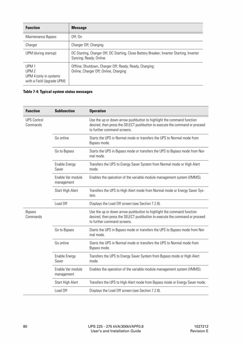
Table 7-4: Typical system status messages
Maintenance Bypass Off; On
Charger Charger Off; Charging
UPM (during startup) DC Starting, Charger Off; DC Starting, Close Battery Breaker; Inverter Starting; Inverter Syncing; Ready; Online
UPM 1UPM 2UPM 4 (only in systems with a Field Upgrade UPM)
Offline; Shutdown, Charger Off; Ready; Ready, Charging;Online, Charger Off; Online, Charging
Function Subfunction Operation
UPS ControlCommands
Use the up or down arrow pushbutton to highlight the command function desired, then press the SELECT pushbutton to execute the command or proceed to further command screens.
Go online Starts the UPS in Normal mode or transfers the UPS to Normal mode from Bypass mode.
Go to Bypass Starts the UPS in Bypass mode or transfers the UPS to Bypass mode from Nor-mal mode.
Enable Energy Saver
Transfers the UPS to Energy Saver System from Normal mode or High Alert mode.
Enable Var module management
Enables the operation of the variable module management system (VMMS).
Start High Alert Transfers the UPS to High Alert mode from Normal mode or Energy Saver Sys-tem.
Load Off Displays the Load Off screen (see Section 7.2.8).
BypassCommands
Use the up or down arrow pushbutton to highlight the command function desired, then press the SELECT pushbutton to execute the command or proceed to further command screens.
Go to Bypass Starts the UPS in Bypass mode or transfers the UPS to Bypass mode from Nor-mal mode.
Go online Starts the UPS in Normal mode or transfers the UPS to Normal mode from Bypass mode.
Enable Energy Saver
Transfers the UPS to Energy Saver System from Bypass mode or High Alert mode.
Enable Var module management
Enables the operation of the variable module management system (VMMS).
Start High Alert Transfers the UPS to High Alert mode from Bypass mode or Energy Saver mode.
Load Off Displays the Load Off screen (see Section 7.2.8).
Function Message
80 UPS 225 - 275 kVA/300kVAPF0.8 1027212User’s and Installation Guide Revision E
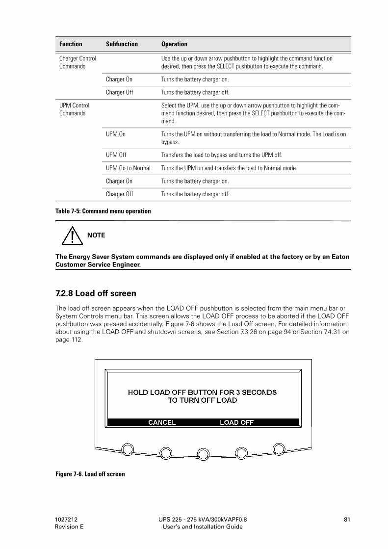
Table 7-5: Command menu operation
NOTE
The Energy Saver System commands are displayed only if enabled at the factory or by an Eaton
Customer Service Engineer.
7.2.8 Load off screen
The load off screen appears when the LOAD OFF pushbutton is selected from the main menu bar or System Controls menu bar. This screen allows the LOAD OFF process to be aborted if the LOAD OFF pushbutton was pressed accidentally. Figure 7-6 shows the Load Off screen. For detailed information about using the LOAD OFF and shutdown screens, see Section 7.3.28 on page 94 or Section 7.4.31 on page 112.
Figure 7-6. Load off screen
Charger Control Commands
Use the up or down arrow pushbutton to highlight the command function desired, then press the SELECT pushbutton to execute the command.
Charger On Turns the battery charger on.
Charger Off Turns the battery charger off.
UPM ControlCommands
Select the UPM, use the up or down arrow pushbutton to highlight the com-mand function desired, then press the SELECT pushbutton to execute the com-mand.
UPM On Turns the UPM on without transferring the load to Normal mode. The Load is on bypass.
UPM Off Transfers the load to bypass and turns the UPM off.
UPM Go to Normal Turns the UPM on and transfers the load to Normal mode.
Charger On Turns the battery charger on.
Charger Off Turns the battery charger off.
Function Subfunction Operation
1027212 UPS 225 - 275 kVA/300kVAPF0.8 81Revision E User’s and Installation Guide
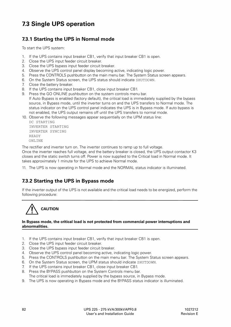
7.3 Single UPS operation
7.3.1 Starting the UPS in Normal mode
To start the UPS system:
1. If the UPS contains input breaker CB1, verify that input breaker CB1 is open.2. Close the UPS input feeder circuit breaker.3. Close the UPS bypass input feeder circuit breaker.4. Observe the UPS control panel display becoming active, indicating logic power.5. Press the CONTROLS pushbutton on the main menu bar. The System Status screen appears.6. On the System Status screen, the UPS status should indicate SHUTDOWN.7. Close the battery breaker.8. If the UPS contains input breaker CB1, close input breaker CB1.9. Press the GO ONLINE pushbutton on the system controls menu bar.
If Auto Bypass is enabled (factory default), the critical load is immediately supplied by the bypass source, in Bypass mode, until the inverter turns on and the UPS transfers to Normal mode. The status indicator on the UPS control panel indicates the UPS is in Bypass mode. If auto bypass is not enabled, the UPS output remains off until the UPS transfers to normal mode.
10. Observe the following messages appear sequentially on the UPM status line:DC STARTINGINVERTER STARTINGINVERTER SYNCINGREADYONLINE
The rectifier and inverter turn on. The inverter continues to ramp up to full voltage. Once the inverter reaches full voltage, and the battery breaker is closed, the UPS output contactor K3 closes and the static switch turns off. Power is now supplied to the Critical load in Normal mode. It takes approximately 1 minute for the UPS to achieve Normal mode.
11. The UPS is now operating in Normal mode and the NORMAL status indicator is illuminated.
7.3.2 Starting the UPS in Bypass mode
If the inverter output of the UPS is not available and the critical load needs to be energized, perform the following procedure:
CAUTION
In Bypass mode, the critical load is not protected from commercial power interruptions and
abnormalities.
1. If the UPS contains input breaker CB1, verify that input breaker CB1 is open.2. Close the UPS input feeder circuit breaker.3. Close the UPS bypass input feeder circuit breaker.4. Observe the UPS control panel becoming active, indicating logic power.5. Press the CONTROLS pushbutton on the main menu bar. The System Status screen appears.6. On the System Status screen, the UPM status should indicate SHUTDOWN.7. If the UPS contains input breaker CB1, close input breaker CB1.8. Press the BYPASS pushbutton on the System Controls menu bar.
The critical load is immediately supplied by the bypass source, in Bypass mode.9. The UPS is now operating in Bypass mode and the BYPASS status indicator is illuminated.
82 UPS 225 - 275 kVA/300kVAPF0.8 1027212User’s and Installation Guide Revision E
7.3.3 Starting the UPMs
To start the power module without transferring the critical load to Normal mode:
1. Unfasten the front door latch and swing the door open (see Figure 4-2 on page 26).2. If the UPS contains input breaker CB1, verify that input breaker CB1 is open.3. Close the UPS input feeder circuit breaker.4. Close the UPS Bypass input feeder circuit breaker.5. If the UPS contains input breaker CB1, close input breaker CB1.6. Close the door and secure the latch.7. Observe the UPS control panel becoming active, indicating logic power.8. Press the CONTROLS pushbutton on the main menu bar. The System Status screen is displayed.9. On the System Status screen, the UPS status should indicate SHUTDOWN and the UPM status
should indicate OFFLINE.10. Verify no alarms are active.11. On the System Status screen, select the UPM command. The UPS Control Command screen is
displayed.12. On the UPS Control Command screen, select the UPM 1 command.13. Press the CONTROLS pushbutton on the UPS Control Command menu bar. The UPM 1 Control
Command screen is displayed.14. On the UPM 1 Control Command screen, select UPM ON.15. Press the SELECT pushbutton on the UPM 1 Command menu bar.16. Verify the following messages display sequentially on the UPM status line:
DC STARTING, CHARGER OFFINVERTER STARTINGINVERTER SYNCINGREADY
The UPM 1 rectifier and inverter turn on. If the Inherent Redundancy option is enabled, a loss of redundancy alarm will be issued. Silence the alarm and continue to Step 17.
17. Repeat Steps 12 through 15 selecting UPM 2 to start UPM 2.18. Verify the following messages display sequentially on the UPM status line:
DC STARTING, CHARGER OFFINVERTER STARTINGINVERTER SYNCINGREADY
The UPM 2 rectifier and inverter turn on. When the inverter reaches full voltage, the UPS is ready to transfer to the Normal mode and supply the critical load.
19. If the UPS is equipped with a Field Upgrade UPM, repeat Steps 12 through 15 selecting UPM 4 to start UPM 4.Verify the following messages display sequentially on the UPM status line:DC STARTING, CHARGER OFFINVERTER STARTINGINVERTER SYNCINGREADY
The UPM 4 rectifier and inverter turn on. When the inverter reaches full voltage, the UPS is ready to transfer to the Normal mode and supply the critical load.
NOTE
To transfer to Normal mode after starting individual UPMs, follow the procedure in Section
7.3.12.
1027212 UPS 225 - 275 kVA/300kVAPF0.8 83Revision E User’s and Installation Guide
7.3.4 Starting a single UPM
To start a single UPM:
1. Unfasten the front door latch and swing the door open (see Figure 4-2 on page 26).2. If the UPS contains input breaker CB1, verify that input breaker CB1 is open.3. Close the UPS input feeder circuit breaker.4. Close the UPS Bypass input feeder circuit breaker.5. If the UPS contains input breaker CB1, close input breaker CB1.6. Close the door and secure the latch.7. Observe the UPS control panel becoming active, indicating logic power.8. Press the CONTROLS pushbutton on the main menu bar. The System Status screen is displayed.9. On the System Status screen, the UPS status should indicate SHUTDOWN and the UPM status
should indicate OFFLINE.10. Verify no alarms are active.11. On the System Status screen, select the UPM command. The UPS Control Command screen is
displayed.12. On the UPS Control Command screen, select the UPM to start.13. Press the CONTROLS pushbutton on the UPS Control Command menu bar. The UPM Control
Command screen is displayed.14. On the UPM Control Command screen, select UPM ON.15. Press the SELECT pushbutton on the UPM Command menu bar.16. Verify the following messages display sequentially on the UPM status line:
DC STARTING, CHARGER OFFINVERTER STARTINGINVERTER SYNCINGREADYThe UPM rectifier and inverter turn on.
17. To transfer the UPM to Normal mode, press the CONTROLS pushbutton on the UPS Control Command menu bar. The UPM Control Command screen is displayed.
18. On the UPM Control Command screen, select UPM GO TO NORMAL.19. Press the SELECT pushbutton on the UPM Command menu bar.
The UPM transfers to Normal mode. The UPM status indicates ONLINE.
7.3.5 Enable Variable Module Management System mode from the UPS
command menu
To enable Variable Module Management System mode:
NOTE
The Variable Module Management System mode commands are displayed only if enabled at the
factory or by an Eaton Customer Service Engineer.
The Variable Module Management System and Energy Saver System modes are mutually
exclusive. If the Energy Saver System mode is enabled, the Variable Module Management
System mode commands will not be displayed.
1. Press the CONTROLS pushbutton on the main menu bar. The System Status screen is displayed.2. On the System Status screen, select the UPS command.3. Press the CONTROLS pushbutton on the System Status menu bar. The UPS Control Command
screen is displayed.4. On the UPS Control Command screen, select ENABLE VAR MODULE MANAGEMENT.
84 UPS 225 - 275 kVA/300kVAPF0.8 1027212User’s and Installation Guide Revision E
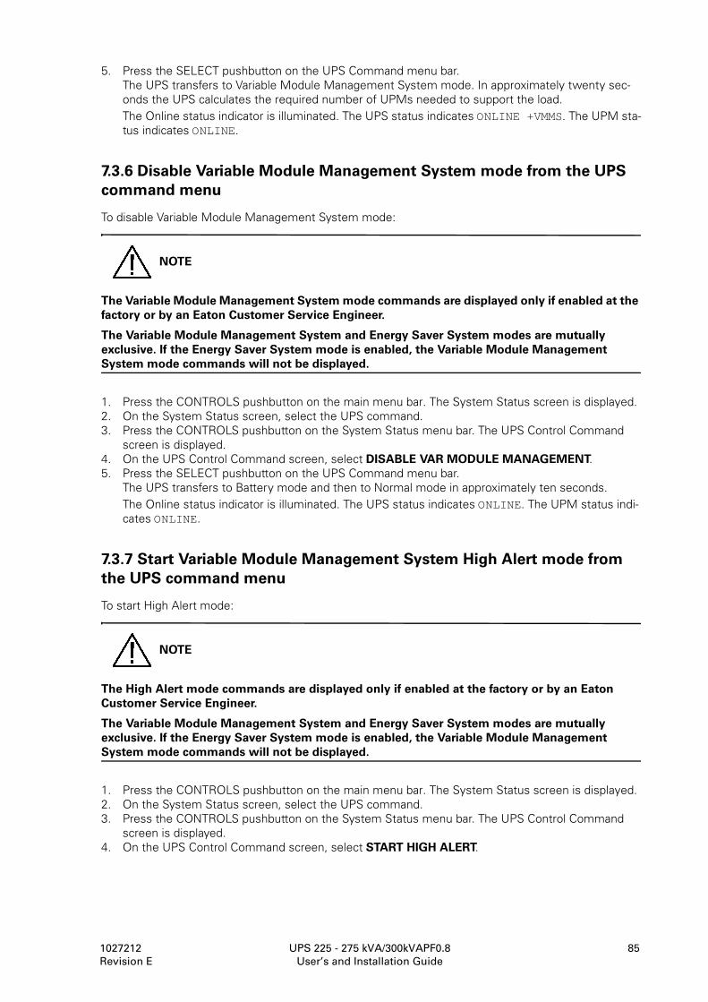
5. Press the SELECT pushbutton on the UPS Command menu bar.The UPS transfers to Variable Module Management System mode. In approximately twenty sec-onds the UPS calculates the required number of UPMs needed to support the load.The Online status indicator is illuminated. The UPS status indicates ONLINE +VMMS. The UPM sta-tus indicates ONLINE.
7.3.6 Disable Variable Module Management System mode from the UPS
command menu
To disable Variable Module Management System mode:
NOTE
The Variable Module Management System mode commands are displayed only if enabled at the
factory or by an Eaton Customer Service Engineer.
The Variable Module Management System and Energy Saver System modes are mutually
exclusive. If the Energy Saver System mode is enabled, the Variable Module Management
System mode commands will not be displayed.
1. Press the CONTROLS pushbutton on the main menu bar. The System Status screen is displayed.2. On the System Status screen, select the UPS command.3. Press the CONTROLS pushbutton on the System Status menu bar. The UPS Control Command
screen is displayed.4. On the UPS Control Command screen, select DISABLE VAR MODULE MANAGEMENT.5. Press the SELECT pushbutton on the UPS Command menu bar.
The UPS transfers to Battery mode and then to Normal mode in approximately ten seconds.The Online status indicator is illuminated. The UPS status indicates ONLINE. The UPM status indi-cates ONLINE.
7.3.7 Start Variable Module Management System High Alert mode from
the UPS command menu
To start High Alert mode:
NOTE
The High Alert mode commands are displayed only if enabled at the factory or by an Eaton
Customer Service Engineer.
The Variable Module Management System and Energy Saver System modes are mutually
exclusive. If the Energy Saver System mode is enabled, the Variable Module Management
System mode commands will not be displayed.
1. Press the CONTROLS pushbutton on the main menu bar. The System Status screen is displayed.2. On the System Status screen, select the UPS command.3. Press the CONTROLS pushbutton on the System Status menu bar. The UPS Control Command
screen is displayed.4. On the UPS Control Command screen, select START HIGH ALERT.
1027212 UPS 225 - 275 kVA/300kVAPF0.8 85Revision E User’s and Installation Guide
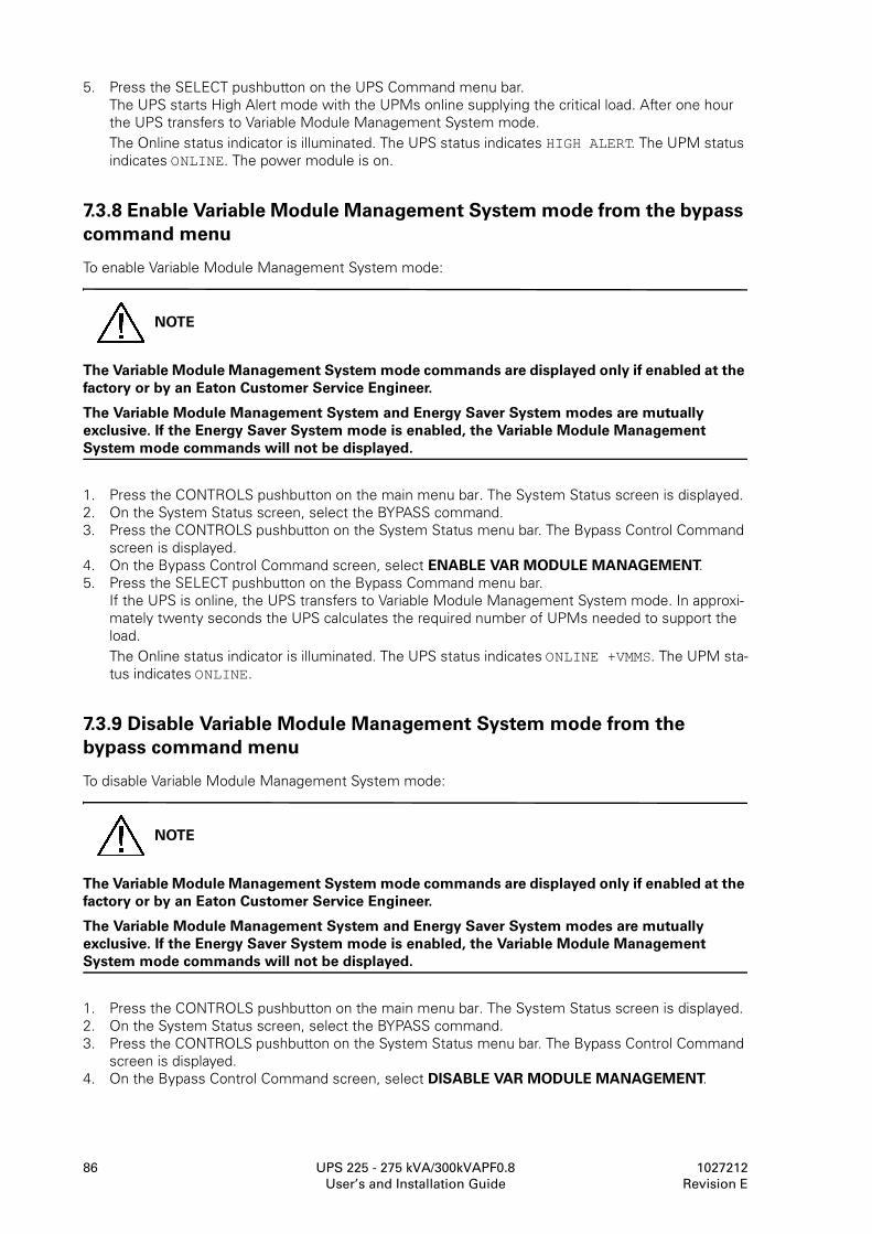
5. Press the SELECT pushbutton on the UPS Command menu bar.The UPS starts High Alert mode with the UPMs online supplying the critical load. After one hour the UPS transfers to Variable Module Management System mode.The Online status indicator is illuminated. The UPS status indicates HIGH ALERT. The UPM status indicates ONLINE. The power module is on.
7.3.8 Enable Variable Module Management System mode from the bypass
command menu
To enable Variable Module Management System mode:
NOTE
The Variable Module Management System mode commands are displayed only if enabled at the
factory or by an Eaton Customer Service Engineer.
The Variable Module Management System and Energy Saver System modes are mutually
exclusive. If the Energy Saver System mode is enabled, the Variable Module Management
System mode commands will not be displayed.
1. Press the CONTROLS pushbutton on the main menu bar. The System Status screen is displayed.2. On the System Status screen, select the BYPASS command.3. Press the CONTROLS pushbutton on the System Status menu bar. The Bypass Control Command
screen is displayed.4. On the Bypass Control Command screen, select ENABLE VAR MODULE MANAGEMENT.5. Press the SELECT pushbutton on the Bypass Command menu bar.
If the UPS is online, the UPS transfers to Variable Module Management System mode. In approxi-mately twenty seconds the UPS calculates the required number of UPMs needed to support the load.The Online status indicator is illuminated. The UPS status indicates ONLINE +VMMS. The UPM sta-tus indicates ONLINE.
7.3.9 Disable Variable Module Management System mode from the
bypass command menu
To disable Variable Module Management System mode:
NOTE
The Variable Module Management System mode commands are displayed only if enabled at the
factory or by an Eaton Customer Service Engineer.
The Variable Module Management System and Energy Saver System modes are mutually
exclusive. If the Energy Saver System mode is enabled, the Variable Module Management
System mode commands will not be displayed.
1. Press the CONTROLS pushbutton on the main menu bar. The System Status screen is displayed.2. On the System Status screen, select the BYPASS command.3. Press the CONTROLS pushbutton on the System Status menu bar. The Bypass Control Command
screen is displayed.4. On the Bypass Control Command screen, select DISABLE VAR MODULE MANAGEMENT.
86 UPS 225 - 275 kVA/300kVAPF0.8 1027212User’s and Installation Guide Revision E
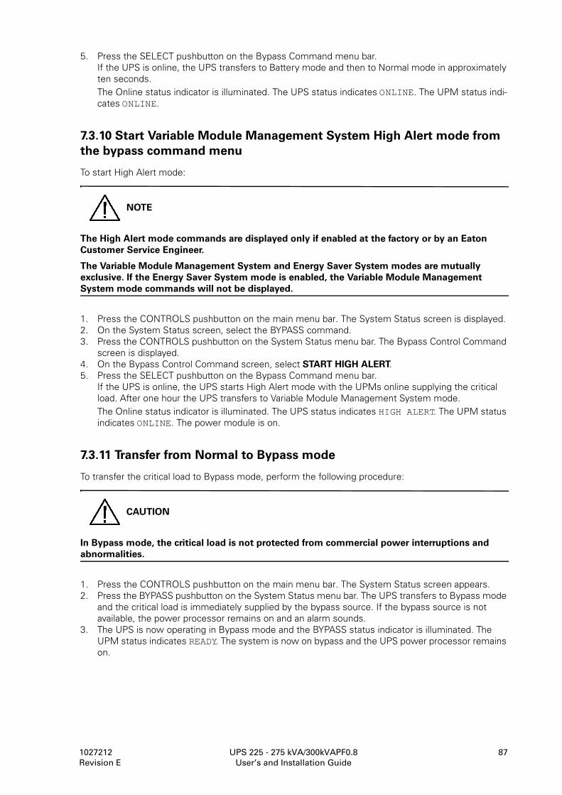
5. Press the SELECT pushbutton on the Bypass Command menu bar.If the UPS is online, the UPS transfers to Battery mode and then to Normal mode in approximately ten seconds.The Online status indicator is illuminated. The UPS status indicates ONLINE. The UPM status indi-cates ONLINE.
7.3.10 Start Variable Module Management System High Alert mode from
the bypass command menu
To start High Alert mode:
NOTE
The High Alert mode commands are displayed only if enabled at the factory or by an Eaton
Customer Service Engineer.
The Variable Module Management System and Energy Saver System modes are mutually
exclusive. If the Energy Saver System mode is enabled, the Variable Module Management
System mode commands will not be displayed.
1. Press the CONTROLS pushbutton on the main menu bar. The System Status screen is displayed.2. On the System Status screen, select the BYPASS command.3. Press the CONTROLS pushbutton on the System Status menu bar. The Bypass Control Command
screen is displayed.4. On the Bypass Control Command screen, select START HIGH ALERT.5. Press the SELECT pushbutton on the Bypass Command menu bar.
If the UPS is online, the UPS starts High Alert mode with the UPMs online supplying the critical load. After one hour the UPS transfers to Variable Module Management System mode.The Online status indicator is illuminated. The UPS status indicates HIGH ALERT. The UPM status indicates ONLINE. The power module is on.
7.3.11 Transfer from Normal to Bypass mode
To transfer the critical load to Bypass mode, perform the following procedure:
CAUTION
In Bypass mode, the critical load is not protected from commercial power interruptions and
abnormalities.
1. Press the CONTROLS pushbutton on the main menu bar. The System Status screen appears.2. Press the BYPASS pushbutton on the System Status menu bar. The UPS transfers to Bypass mode
and the critical load is immediately supplied by the bypass source. If the bypass source is not available, the power processor remains on and an alarm sounds.
3. The UPS is now operating in Bypass mode and the BYPASS status indicator is illuminated. The UPM status indicates READY. The system is now on bypass and the UPS power processor remains on.
1027212 UPS 225 - 275 kVA/300kVAPF0.8 87Revision E User’s and Installation Guide
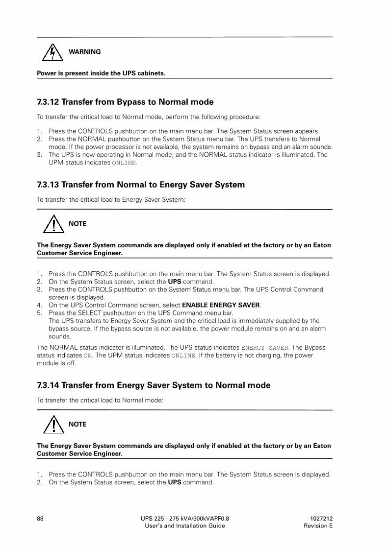
WARNING
Power is present inside the UPS cabinets.
7.3.12 Transfer from Bypass to Normal mode
To transfer the critical load to Normal mode, perform the following procedure:
1. Press the CONTROLS pushbutton on the main menu bar. The System Status screen appears.2. Press the NORMAL pushbutton on the System Status menu bar. The UPS transfers to Normal
mode. If the power processor is not available, the system remains on bypass and an alarm sounds.3. The UPS is now operating in Normal mode, and the NORMAL status indicator is illuminated. The
UPM status indicates ONLINE.
7.3.13 Transfer from Normal to Energy Saver System
To transfer the critical load to Energy Saver System:
NOTE
The Energy Saver System commands are displayed only if enabled at the factory or by an Eaton
Customer Service Engineer.
1. Press the CONTROLS pushbutton on the main menu bar. The System Status screen is displayed.2. On the System Status screen, select the UPS command.3. Press the CONTROLS pushbutton on the System Status menu bar. The UPS Control Command
screen is displayed.4. On the UPS Control Command screen, select ENABLE ENERGY SAVER.5. Press the SELECT pushbutton on the UPS Command menu bar.
The UPS transfers to Energy Saver System and the critical load is immediately supplied by the bypass source. If the bypass source is not available, the power module remains on and an alarm sounds.
The NORMAL status indicator is illuminated. The UPS status indicates ENERGY SAVER. The Bypass status indicates ON. The UPM status indicates ONLINE. If the battery is not charging, the power module is off.
7.3.14 Transfer from Energy Saver System to Normal mode
To transfer the critical load to Normal mode:
NOTE
The Energy Saver System commands are displayed only if enabled at the factory or by an Eaton
Customer Service Engineer.
1. Press the CONTROLS pushbutton on the main menu bar. The System Status screen is displayed.2. On the System Status screen, select the UPS command.
88 UPS 225 - 275 kVA/300kVAPF0.8 1027212User’s and Installation Guide Revision E
3. Press the CONTROLS pushbutton on the System Status menu bar. The UPS Control Command screen is displayed.
4. On the UPS Control Command screen, select GO ONLINE.5. Press the SELECT pushbutton on the UPS Command menu bar.
The UPS transfers to Battery mode and then to Normal mode. If the power module is not available, the system remains on bypass and an alarm sounds.
The NORMAL status indicator is illuminated. The UPS status indicates ONLINE. The UPM status indicates ONLINE.
7.3.15 Transfer from Normal to High Alert mode
To transfer the critical load to High Alert mode:
NOTE
The High Alert mode commands are displayed only if enabled at the factory or by an Eaton
Customer Service Engineer.
1. On any UPS, press the CONTROLS pushbutton on the main menu bar. The System Status screenis displayed.
2. On the System Status screen, select the UPS command.3. Press the CONTROLS pushbutton on the System Status menu bar. The UPS Control Command
screen is displayed.4. On the UPS Control Command screen, select START HIGH ALERT.5. Press the SELECT pushbutton on the UPS Command menu bar.
The UPS transfers to High Alert mode, but remains online. After one hour the UPS transfers to Energy Saver System and the critical load is immediately supplied by the bypass source. If the bypass source is not available, the power module remains on and an alarm sounds.The NORMAL status indicator is illuminated. The UPS status indicates HIGH ALERT. The UPM sta-tus indicates ONLINE. The power module is on.
7.3.16 Transfer from High Alert to Normal mode
To transfer the critical load to Normal mode:
NOTE
The High Alert mode commands are displayed only if enabled at the factory or by an Eaton
Customer Service Engineer.
1. Press the CONTROLS pushbutton on the main menu bar. The System Status screen is displayed.2. On the System Status screen, select the UPS command.3. Press the CONTROLS pushbutton on the System Status menu bar. The UPS Control Command
screen is displayed.4. On the UPS Control Command screen, select GO ONLINE.5. Press the SELECT pushbutton on the UPS Command menu bar.
The UPS transfers to Normal mode. The NORMAL status indicator is illuminated. The UPS status indicates ONLINE. The UPM status indicates ONLINE.
1027212 UPS 225 - 275 kVA/300kVAPF0.8 89Revision E User’s and Installation Guide
7.3.17 Transfer from Bypass to Energy Saver System
To transfer the critical load to Energy Saver System:
NOTE
The Energy Saver System commands are displayed only if enabled at the factory or by an Eaton
Customer Service Engineer.
1. Press the CONTROLS pushbutton on the main menu bar. The System Status screen is displayed.2. On the System Status screen, select the BYPASS command.3. Press the CONTROLS pushbutton on the System Status menu bar. The Bypass Control Command
screen is displayed.4. On the Bypass Control Command screen, select ENABLE ENERGY SAVER.5. Press the SELECT pushbutton on the Bypass Command menu bar.
The UPS transfers to Normal mode and then to Energy Saver System. The critical load is supplied by the bypass source.The NORMAL status indicator is illuminated. The UPS status indicates ENERGY SAVER. The Bypass status indicates ON. The UPM status indicates ONLINE. If the battery is not charging, the power module is off.
7.3.18 Transfer from Energy Saver System to Bypass mode
To transfer the critical load to Bypass mode:
NOTE
The Energy Saver System commands are displayed only if enabled at the factory or by an Eaton
Customer Service Engineer.
1. Press the CONTROLS pushbutton on the main menu bar. The System Status screen is displayed.2. On the System Status screen, select the BYPASS command.3. Press the CONTROLS pushbutton on the System Status menu bar. The Bypass Control Command
screen is displayed.4. On the Bypass Control Command screen, select GO TO BYPASS.5. Press the SELECT pushbutton on the Bypass Command menu bar.
The UPS transfers to Battery mode and then to Bypass mode.The BYPASS status indicator is illuminated. The UPS status indicates READY. The Bypass status indicates ON. The UPM status indicates READY. The power module remains on.
7.3.19 Transfer from Bypass to High Alert mode
To transfer the critical load to High Alert mode:
NOTE
The High Alert mode commands are displayed only if enabled at the factory or by an Eaton
Customer Service Engineer.
90 UPS 225 - 275 kVA/300kVAPF0.8 1027212User’s and Installation Guide Revision E
1. Press the CONTROLS pushbutton on the main menu bar. The System Status screen is displayed.2. On the System Status screen, select the BYPASS command.3. Press the CONTROLS pushbutton on the System Status menu bar. The Bypass Control Command
screen is displayed.4. On the Bypass Control Command screen, select START HIGH ALERT.5. Press the SELECT pushbutton on the Bypass Command menu bar.
The UPS transfers to High Alert mode, but remains online. After one hour the UPS transfers to Energy Saver System and the critical load is immediately supplied by the bypass source. If the bypass source is not available, the power module remains on and an alarm sounds.The NORMAL status indicator is illuminated. The UPS status indicates HIGH ALERT. The UPM sta-tus indicates ONLINE. The power module is on.
7.3.20 Transfer from High Alert to Bypass mode
To transfer the critical load to Bypass mode:
NOTE
The High Alert mode commands are displayed only if enabled at the factory or by an Eaton
Customer Service Engineer.
1. Press the CONTROLS pushbutton on the main menu bar. The System Status screen is displayed.2. On the System Status screen, select the BYPASS command.3. Press the CONTROLS pushbutton on the System Status menu bar. The Bypass Control Command
screen is displayed.4. On the Bypass Control Command screen, select GO TO BYPASS.5. Press the SELECT pushbutton on the Bypass Command menu bar.
The UPS transfers to Bypass mode and the critical load is immediately supplied by the bypass source. If the bypass source is not available, the power module remains on and an alarm sounds.The BYPASS status indicator is illuminated. The UPS status indicates BYPASS. The Bypass status indicates ON. The UPM status indicates READY. The power module remains on.
7.3.21 Transfer from Energy Saver System to High Alert mode
To transfer the critical load to High Alert mode:
NOTE
The Energy Saver System and High Alert mode commands are displayed only if enabled at the
factory or by an Eaton Customer Service Engineer.
1. Press the CONTROLS pushbutton on the main menu bar. The System Status screen is displayed.2. On the System Status screen, select the UPS command.3. Press the CONTROLS pushbutton on the System Status menu bar. The UPS Control Command
screen is displayed.4. On the UPS Control Command screen, select START HIGH ALERT.
1027212 UPS 225 - 275 kVA/300kVAPF0.8 91Revision E User’s and Installation Guide
5. Press the SELECT pushbutton on the UPS Command menu bar.The UPS transfers to Battery mode and then to High Alert mode. After one hour the UPS transfers to Energy Saver System and the critical load is immediately supplied by the bypass source. If the bypass source is not available, the power module remains on and an alarm sounds.The NORMAL status indicator is illuminated. The UPS status indicates HIGH ALERT. The UPM sta-tus indicates ONLINE. The power module is on.
7.3.22 Transfer from High Alert to Energy Saver System
To transfer the critical load to Energy Saver System:
NOTE
The High Alert and Energy Saver System commands are displayed only if enabled at the factory
or by an Eaton Customer Service Engineer.
1. Press the CONTROLS pushbutton on the main menu bar. The System Status screen is displayed.2. On the System Status screen, select the UPS command.3. Press the CONTROLS pushbutton on the System Status menu bar. The UPS Control Command
screen is displayed.4. On the UPS Control Command screen, select ENABLE ENERGY SAVER.5. Press the SELECT pushbutton on the UPS Command menu bar.
The UPS transfers to Energy Saver System and the critical load is immediately supplied by the bypass source. If the bypass source is not available, the power module remains on and an alarm sounds.The NORMAL status indicator is illuminated. The UPS status indicates ENERGY SAVER. The Bypass status indicates ON. The UPM status indicates ONLINE. If the battery is not charging, the power module is off.
7.3.23 Transfer from Normal to Bypass mode and shut down UPS
To transfer the critical load to Bypass mode and shut down the UPS, perform the following procedure:
1. Transfer the critical load to bypass by performing the procedure in Section 7.3.11.2. Press the CONTROLS pushbutton on the main menu bar. The System Status screen appears.3. Press the pushbutton to display System Controls Screen 2.4. Press the UPM OFF pushbutton on the System Controls menu bar.
The UPM status indicates SHUTDOWN. The input and output contactors open, the battery breaker or disconnect is tripped, and the power module is turned off. The bypass source supplies the critical load.
WARNING
Power is present inside the UPS cabinets.
7.3.24 Single UPM shutdown
To shutdown a single UPM:
1. Press the CONTROLS pushbutton on the main menu bar. The System Status screen is displayed.
92 UPS 225 - 275 kVA/300kVAPF0.8 1027212User’s and Installation Guide Revision E
2. On the System Status screen, select the UPM Command. The UPS Control Command screen is displayed.
3. On the UPS Control Command screen, select the UPM to shutdown.4. Press the CONTROLS pushbutton on the UPS Control Command menu bar. The UPM Control
Command screen is displayed.5. On the UPM Control Command screen, select UPM OFF.6. Press the SELECT pushbutton on the UPM Command menu bar.
The UPM status indicates READY. The output contactor opens. The power module remains on. The remaining UPMs supply the critical load.
7. To turn off the power module, press the CONTROLS pushbutton on the UPS Control Command menu bar. The UPM Control Command screen is displayed.
8. On the UPM Control Command screen, select UPM OFF.9. Press the SELECT pushbutton on the UPM Command menu bar.
The UPM status indicates SHUTDOWN. The power module is turned off. The remaining UPMs con-tinue to supply the critical load.
Logic power remains on.
7.3.25 Single UPM restart
To restart a single UPM from a shutdown state:
1. Press the CONTROLS pushbutton on the main menu bar. The System Status screen is displayed.2. On the System Status screen, select the UPM command. The UPS Control Command screen is
displayed.3. On the UPS Control Command screen, select the UPM to restart.4. Press the CONTROLS pushbutton on the UPS Control Command menu bar. The UPM Control
Command screen is displayed.5. On the UPM Control Command screen, select UPM ON.6. Press the SELECT pushbutton on the UPM Command menu bar.7. Verify the following messages display sequentially on the UPM status line:
DC STARTING, CHARGER OFFINVERTER STARTINGINVERTER SYNCINGREADYThe UPM rectifier and inverter turn on.
8. To transfer the UPM to Normal mode, press the CONTROLS pushbutton on the UPS Control Command menu bar. The UPM Control Command screen is displayed.
9. On the UPM Control Command screen, select UPM GO TO NORMAL.10. Press the SELECT pushbutton on the UPM Command menu bar.
The UPM transfers to Normal mode. The UPM status indicates ONLINE.
7.3.26 UPS and critical load shutdown
To perform maintenance or service on the critical load, shut down power to the load by performing the following procedure:
1. Turn off all equipment that is being powered by the UPS.2. Perform the LOAD OFF procedure in Section 7.3.28. The input, output, and bypass backfeed
contactors open, the battery breaker or disconnect is tripped, and the power module is turned off.
1027212 UPS 225 - 275 kVA/300kVAPF0.8 93Revision E User’s and Installation Guide
WARNING
Power is present inside the UPS cabinet until the upstream input feeder circuit breaker is
opened.
3. If the UPS contains input breaker CB1, open the UPS input breaker CB1.4. Open the UPS input and bypass feeder circuit breakers.
7.3.27 Charger control
To turn the battery charger on or off, perform the following procedure:
1. Press the CONTROLS pushbutton on the main menu bar. The System Status screen appears.2. Scroll down to the charger.3. Press the CONTROLS pushbutton on the System Controls menu bar to enter the charger
command menu.
7.3.28 Using the UPS LOAD OFF pushbutton
A UPS Load Off is initiated by the LOAD OFF pushbutton from the main menu bar or the System Controls menu bar. This pushbutton can be pressed to control the UPS output. The UPS LOAD OFF pushbutton de-energizes the critical load and powers down the UPS.
The UPS (including Bypass) remains off until restarted.
To use the LOAD OFF pushbutton:
1. Press the LOAD OFF pushbutton.The Load Off screen appears, providing a choice to proceed or abort the shutdown.
CAUTION
All power to the critical load is lost when the LOAD OFF is selected in the following step. You
should use this feature only when you want to de-energize the critical load.
2. To shut down the UPS, press LOAD OFF from the Load Off menu bar, and hold for three seconds. To abort the shutdown, press CANCEL. When LOAD OFF is selected and held for three seconds, the input, output, and bypass backfeed contactors open, the battery breaker or disconnect is tripped, and all the UPMs are turned off.
CAUTION
Do not attempt to restart the system after Load Off until the cause of the shutdown has been
identified and cleared.
3. To restart the UPS after pressing the LOAD OFF pushbutton, follow the procedure in Section 7.3.1 or Section 7.3.2.
94 UPS 225 - 275 kVA/300kVAPF0.8 1027212User’s and Installation Guide Revision E
7.3.29 Using the Remote Emergency Power-off switch
A UPS emergency power-off is initiated by the REPO pushbutton switch. In an emergency, you can use this switch to control the UPS output. The REPO switch de-energizes the critical load and powers down the UPS immediately, without asking for verification. The UPS, including Bypass, remains off until restarted.
CAUTION
All power to the critical load is lost when the REPO switch is activated in the following step. You
should use this feature only when you want to de-energize the critical load.
NOTE
The following instructions are for the Eaton Corporation-supplied REPO switch. If a customer-
supplied REPO switch is used, it may not activate in the same manner; refer to the operating
instructions provided with the switch.
To use the REPO switch:
1. Press the REPO pushbutton switch.
The input, output, and bypass backfeed contactors open, the battery breaker or disconnect is tripped, and the power module is turned off immediately, without asking for verification.
CAUTION
Do not attempt to restart the system after Load Off until the cause of the shutdown has been
identified and cleared.
2. To restart the UPS after using the REPO pushbutton, reset the REPO switch and then follow the procedure in Section 7.3.1 or Section 7.3.2.
7.3.30 Using Mechanical Bypass Switch
The operation of the integral MBS is allowed for a trained person only who is familiar with the UPS behaviour and functions. The full UPS wiring diagram with a MBS switch is presented in the installation part of the manual.
NOTE
The integral MBS and Static Bypass need to supplied by the same source.
1027212 UPS 225 - 275 kVA/300kVAPF0.8 95Revision E User’s and Installation Guide
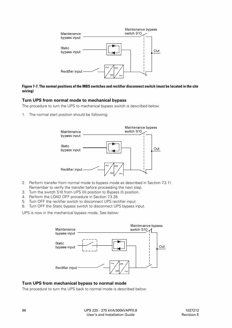
Figure 7-7. The normal positions of the MBS switches and rectifier disconnect switch (must be located in the site wiring)
Turn UPS from normal mode to mechanical bypass
The procedure to turn the UPS to mechanical bypass switch is described below.
1. The normal start position should be following:
2. Perform transfer from normal mode to bypass mode as described in Section 7.3.11.Remember to verify the transfer before proceeding the next step.
3. Turn the switch S10 from UPS (II) position to Bypass (I) position.4. Perform the LOAD OFF procedure in Section 7.3.28. 5. Turn OFF the rectifier switch to disconnect UPS rectifier input.6. Turn OFF the Static bypass switch to disconnect UPS bypass input.
UPS is now in the mechanical bypass mode, See below:
Turn UPS from mechanical bypass to normal mode
The procedure to turn the UPS back to normal mode is described below.
96 UPS 225 - 275 kVA/300kVAPF0.8 1027212User’s and Installation Guide Revision E
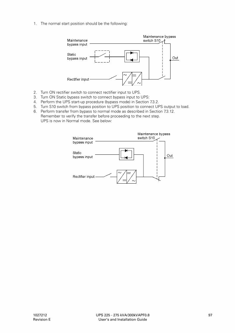
1. The normal start position should be the following:
2. Turn ON rectifier switch to connect rectifier input to UPS.3. Turn ON Static bypass switch to connect bypass input to UPS:4. Perform the UPS start-up procedure (bypass mode) in Section 7.3.2.5. Turn S10 switch from bypass position to UPS position to connect UPS output to load.6. Perform transfer from bypass to normal mode as described in Section 7.3.12.
Remember to verify the transfer before proceeding to the next step.UPS is now in Normal mode. See below:
1027212 UPS 225 - 275 kVA/300kVAPF0.8 97Revision E User’s and Installation Guide
7.4 Multiple UPS distributed bypass operation
7.4.1 Starting the distributed bypass system in normal mode
To start the distributed bypass system:
1. Unfasten the front door latches and swing the doors open on all of the UPSs (see Figure 4-2 onpage 26).
2. If the UPSs contain input breakers (CB1), verify that all input breakers are open.3. Close all Module Output Breakers (MOBs).4. Close all UPS input feeder circuit breakers. 5. If the UPSs contain input breakers (CB1), close all input breakers.6. Close all UPS Bypass input feeder circuit breakers.7. Close the doors and secure the latches.8. Observe the UPS control panel displays becoming active, indicating logic power.9. On any UPS, press the CONTROLS pushbutton on the main menu bar. The System Status screen
is displayed.10. On the System Status screen, verify the UPS status is SHUTDOWN and the UPM status is
SHUTDOWN.11. Close all battery breakers.12. Verify no alarms are active.13. On the System Status screen, select the UPS command.14. Press the CONTROLS pushbutton on the System Status menu bar. The UPS Control Command
screen is displayed.15. On the UPS Control Command screen, select GO ONLINE.16. Press the SELECT pushbutton on the UPS Command menu bar.
If Auto Bypass is enabled (factory default), the critical load is immediately supplied by the bypass source in Bypass mode from all UPSs, until the inverter turns on and the UPSs transfer to Normal mode. The status indicator on the UPS control panel indicates the UPS is in Bypass mode. If Auto Bypass is not enabled, the UPS outputs remain off until the UPSs transfer to Normal mode.
17. Verify the following messages display sequentially on the UPS status line:DC STARTING, CHARGER OFFINVERTER STARTINGINVERTER SYNCINGONLINE, CHARGER ON
The rectifier and inverter turn on. The inverter continues to ramp up to full voltage.
Once the inverter reaches full voltage, all UPS output contactors (K3) close and the bypass circuits open. Power is now supplied to the critical load in Normal mode from all UPSs. It takes approximately one minute for the UPSs to achieve Normal mode.
The NORMAL status indicator is illuminated. The UPS status indicates ONLINE. The UPM status indicates ONLINE, CHARGER ON.
7.4.2 Starting the distributed bypass system in Bypass mode
If the inverter output of the distributed bypass system is not available and the critical load needs to be energized:
CAUTION
In Bypass mode, the critical load is not protected from commercial power interruptions and
abnormalities.
98 UPS 225 - 275 kVA/300kVAPF0.8 1027212User’s and Installation Guide Revision E
1. Unfasten the front door latches and swing the doors open on all of the UPSs (see Figure 4-2 onpage 26).
2. If the UPSs contain input breakers (CB1), verify that all input breakers are open.3. Close all MOBs.4. Close all UPS input feeder circuit breakers.5. If the UPSs contain input breakers (CB1), close all input breakers.6. Close all UPS Bypass input feeder circuit breakers.7. Close the doors and secure the latches.8. Observe the UPS control panel displays becoming active, indicating logic power.9. On any UPS, press the CONTROLS pushbutton on the main menu bar. The System Status screen
is displayed.10. On the System Status screen, verify that the status of the UPS and UPM is SHUTDOWN.11. On the System Status screen, select the BYPASS command.12. Press the CONTROLS pushbutton on the System Status menu bar. The Bypass Control Command
screen is displayed.13. On the Bypass Control Command screen, select GO TO BYPASS.14. Press the SELECT pushbutton on the Bypass Command menu bar.
The critical load is immediately supplied by the bypass source in Bypass mode from all UPSs.The BYPASS status indicator is illuminated. The Bypass status indicates ON. The UPM status indi-cates SHUTDOWN, CLOSE BATTERY.
7.4.3 Enable Variable Module Management System mode from the UPS
command menu
For instructions, see Section 7.3.5 “Enable Variable Module Management System mode from the UPS command menu” on page 84.
7.4.4 Disable Variable Module Management System mode from the UPS
command menu
For instructions, see Section 7.3.6 “Disable Variable Module Management System mode from the UPS command menu” on page 85.
7.4.5 Start Variable Module Management System High Alert mode from
the UPS command menu
For instructions, see Section 7.3.7 “Start Variable Module Management System High Alert mode from the UPS command menu” on page 85.
7.4.6 Enable Variable Module Management System mode from the bypass
command menu
For instructions, see Section 7.3.8 “Enable Variable Module Management System mode from the bypass command menu” on page 86.
7.4.7 Disable Variable Module Management System Mode from the
bypass command menu
For instructions, see Section 7.3.9 “Disable Variable Module Management System mode from the bypass command menu” on page 86.
1027212 UPS 225 - 275 kVA/300kVAPF0.8 99Revision E User’s and Installation Guide
7.4.8 Start Variable Module Management System High Alert mode from
the bypass command menu
For instructions, see Section 7.3.10 “Start Variable Module Management System High Alert mode from the bypass command menu” on page 87.
7.4.9 Starting the UPS UPMs
To start the power modules without transferring the critical load to Normal mode:
1. Unfasten the front door latches and swing the doors open on all of the UPSs (see Figure 4-2 onpage 26).
2. If the UPSs contain input breakers (CB1), verify that all input breakers are open.3. Close all UPS input feeder circuit breakers.4. If the UPSs contain input breakers (CB1), close all input breakers.5. Close all UPS Bypass input feeder circuit breakers.6. Close the doors and secure the latches.7. Observe the UPS control panel displays becoming active, indicating logic power.8. On any UPS, press the CONTROLS pushbutton on the main menu bar. The System Status screen
is displayed.9. On the System Status screen, verify the UPS status is SHUTDOWN and the UPM status is OFFLINE.10. Verify no alarms are active.11. On the System Status screen, select the UPM command. The UPS Control Command screen is
displayed.12. On the UPS Control Command screen, select the UPM 1 command.13. Press the CONTROLS pushbutton on the UPS Control Command menu bar. The UPM 1 Control
Command screen is displayed.14. On the UPM 1 Control Command screen, select UPM ON.15. Press the SELECT pushbutton on the UPM 1 Command menu bar.16. Verify the following messages display sequentially on the UPM status line:
DC STARTING, CHARGER OFFINVERTER STARTINGINVERTER SYNCINGREADYThe UPM 1 rectifier and inverter turn on.If the Inherent Redundancy option is enabled, a loss of redundancy alarm will be issued. Silence the alarm and continue to Step 17.
17. Repeat Steps 12 through 15 selecting UPM 2 to start UPM 2.18. Verify the following messages display sequentially on the UPM status line:
DC STARTING, CHARGER OFFINVERTER STARTINGINVERTER SYNCINGREADYThe UPM 2 rectifier and inverter turn on.
19. If the UPS is a equipped with a field upgrade UPM, repeat Steps 12 through 15 selecting UPM 4 to start UPM 4.
20. Verify the following messages display sequentially on the UPM status line:DC STARTING, CHARGER OFFINVERTER STARTINGINVERTER SYNCINGREADYThe UPM 4 rectifier and inverter turn on. When the inverter reaches full voltage, the UPS is ready to transfer to the Normal mode and supply the critical load.
21. Repeat Steps 1 through 20 for each UPS in the distributed bypass system.
100 UPS 225 - 275 kVA/300kVAPF0.8 1027212User’s and Installation Guide Revision E
NOTE
To transfer to Normal mode after starting individual UPMs, follow the procedure in Section
7.4.12.
7.4.10 Starting a single UPM
To start a single UPM:
1. Unfasten the front door latch and swing the door open (see Figure 4-2 on page 26).2. If the UPS contains input breaker CB1, verify that input breaker CB1 is open.3. Close the UPS input feeder circuit breaker.4. If the UPSs contain input breakers (CB1), close all input breakers.5. Close the UPS Bypass input feeder circuit breaker.6. Close the door and secure the latch.7. Observe the UPS control panel becoming active, indicating logic power.8. Press the CONTROLS pushbutton on the main menu bar. The System Status screen is displayed.
On the System Status screen, the UPS status and the UPM status should indicate SHUTDOWN.9. Verify no alarms are active.10. On the System Status screen, select the UPM command. The UPS Control Command screen is
displayed.11. On the UPS Control Command screen, select the UPM to start.12. Press the CONTROLS pushbutton on the UPS Control Command menu bar. The UPM Control
Command screen is displayed.13. On the UPM Control Command screen, select UPM ON.14. Press the SELECT pushbutton on the UPM Command menu bar.15. Verify the following messages display sequentially on the UPM status line:
DC STARTING, CHARGER OFFINVERTER STARTINGINVERTER SYNCINGREADYThe UPM rectifier and inverter turn on.
16. To transfer the UPM to Normal mode, press the CONTROLS pushbutton on the UPS Control Command menu bar. The UPM Control Command screen is displayed.
17. On the UPM Control Command screen, select UPM GO TO NORMAL.18. Press the SELECT pushbutton on the UPM Command menu bar.
The UPM transfers to Normal mode. The UPM status indicates ONLINE.
7.4.11 Transfer from Normal to Bypass mode
To transfer the critical load to Bypass mode:
CAUTION
In Bypass mode, the critical load is not protected from commercial power interruptions and
abnormalities.
1. On any UPS, press the CONTROLS pushbutton on the main menu bar. The System Status screenis displayed.
2. On the System Status screen, select the BYPASS command.
1027212 UPS 225 - 275 kVA/300kVAPF0.8 101Revision E User’s and Installation Guide
3. Press the CONTROLS pushbutton on the System Status menu bar. The Bypass Control Command screen is displayed.
4. On the Bypass Control Command screen, select GO TO BYPASS.5. Press the SELECT pushbutton on the Bypass Command menu bar.
All of the UPSs transfer to Bypass mode and the critical load is immediately supplied by the bypass source. If the bypass source is not available, the power module remains on and an alarm sounds.The BYPASS status indicator is illuminated. The Bypass status indicates ON. The UPM status indi-cates READY. The power module remains on.
WARNING
Power is present inside the UPS cabinet.
7.4.12 Transfer from Bypass to Normal mode
To transfer the critical load to Normal mode:
1. If not already closed, close the battery breaker.2. On any UPS, press the CONTROLS pushbutton on the main menu bar. The System Status screen
is displayed.3. On the System Status screen, select the UPS command.4. Press the CONTROLS pushbutton on the System Status menu bar. The UPS Control Command
screen is displayed.5. On the UPS Control Command screen, select GO ONLINE.6. Press the SELECT pushbutton on the UPS Command menu bar.
All of the UPSs transfer to Normal mode. If the power module is not available, the system remains on bypass and an alarm sounds.The NORMAL status indicator is illuminated. The UPS status indicates ONLINE.The UPM status indicates ONLINE.
7.4.13 Transfer from Normal to Energy Saver System
To transfer the critical load to Energy Saver System:
NOTE
The Energy Saver System commands are displayed only if enabled at the factory or by an Eaton
Customer Service Engineer.
1. On any UPS, press the CONTROLS pushbutton on the main menu bar. The System Status screenis displayed.
2. On the System Status screen, select the UPS command.3. Press the CONTROLS pushbutton on the System Status menu bar. The UPS Control Command
screen is displayed.4. On the UPS Control Command screen, select ENABLE ENERGY SAVER.5. Press the SELECT pushbutton on the UPS Command menu bar.
All of the UPSs transfer to Energy Saver System and the critical load is immediately supplied by the bypass source. If the bypass source is not available, the power module remains on and an alarm sounds.The NORMAL status indicator is illuminated. The UPS status indicates ENERGY SAVER. The Bypass status indicates ON. The UPM status indicates ONLINE.
102 UPS 225 - 275 kVA/300kVAPF0.8 1027212User’s and Installation Guide Revision E
7.4.14 Transfer from Energy Saver System to Normal mode
To transfer the critical load to Normal mode:
NOTE
The Energy Saver System commands are displayed only if enabled at the factory or by an Eaton
Customer Service Engineer.
1. On any UPS, press the CONTROLS pushbutton on the main menu bar. The System Status screenis displayed.
2. On the System Status screen, select the UPS command.3. Press the CONTROLS pushbutton on the System Status menu bar. The UPS Control Command
screen is displayed.4. On the UPS Control Command screen, select GO ONLINE.5. Press the SELECT pushbutton on the UPS Command menu bar.
All of the UPSs transfer to Battery mode and then to Normal mode. If the power module is not available, the system remains on bypass and an alarm sounds.The NORMAL status indicator is illuminated. The UPS status indicates ONLINE. The UPM status indicates ONLINE.
7.4.15 Transfer from Normal to High Alert mode
To transfer the critical load to High Alert mode:
NOTE
The High Alert mode commands are displayed only if enabled at the factory or by an Eaton
Customer Service Engineer.
1. On any UPS, press the CONTROLS pushbutton on the main menu bar. The System Status screenis displayed.
2. On the System Status screen, select the UPS command.3. Press the CONTROLS pushbutton on the System Status menu bar. The UPS Control Command
screen is displayed.4. On the UPS Control Command screen, select START HIGH ALERT.5. Press the SELECT pushbutton on the UPS Command menu bar.
All of the UPSs transfer to High Alert mode, but remain online. After one hour the UPSs transfer to Energy Saver System and the critical load is immediately supplied by the bypass source. If the bypass source is not available, the power module remains on and an alarm sounds.The NORMAL status indicator is illuminated. The UPS status indicates HIGH ALERT. The UPM sta-tus indicates ONLINE. The power module is on.
1027212 UPS 225 - 275 kVA/300kVAPF0.8 103Revision E User’s and Installation Guide
7.4.16 Transfer from High Alert to Normal mode
To transfer the critical load to Normal mode:
NOTE
The High Alert mode commands are displayed only if enabled at the factory or by an Eaton
Customer Service Engineer.
1. On any UPS, press the CONTROLS pushbutton on the main menu bar. The System Status screenis displayed.
2. On the System Status screen, select the UPS command.3. Press the CONTROLS pushbutton on the System Status menu bar. The UPS Control Command
screen is displayed.4. On the UPS Control Command screen, select GO ONLINE.5. Press the SELECT pushbutton on the UPS Command menu bar.
All of the UPSs transfer to Normal mode. The NORMAL status indicator is illuminated. The UPS status indicates ONLINE. The UPM status indicates ONLINE.
7.4.17 Transfer from Bypass to Energy Saver System
To transfer the critical load to Energy Saver System:
NOTE
The Energy Saver mode commands are displayed only if enabled at the factory or by an Eaton
Customer Service Engineer.
1. On any UPS, press the CONTROLS pushbutton on the main menu bar. The System Status screenis displayed.
2. On the System Status screen, select the BYPASS command.3. Press the CONTROLS pushbutton on the System Status menu bar. The Bypass Control Command
screen is displayed.4. On the Bypass Control Command screen, select ENABLE ENERGY SAVER.5. Press the SELECT pushbutton on the Bypass Command menu bar.
All of the UPSs transfer to Normal mode and then to Energy Saver System. The critical load is sup-plied by the bypass source.The NORMAL status indicator is illuminated. The UPS status indicates ENERGY SAVER. The Bypass status indicates ON. The UPM status indicates ONLINE. If the battery is not charging, the power module is off.
7.4.18 Transfer from Energy Saver System to Bypass mode
To transfer the critical load to Bypass mode:
NOTE
The Energy Saver System commands are displayed only if enabled at the factory by an Eaton
Customer Service Engineer.
104 UPS 225 - 275 kVA/300kVAPF0.8 1027212User’s and Installation Guide Revision E
1. On any UPS, press the CONTROLS pushbutton on the main menu bar. The System Status screenis displayed.
2. On the System Status screen, select the BYPASS command.3. Press the CONTROLS pushbutton on the System Status menu bar. The Bypass Control Command
screen is displayed.4. On the Bypass Control Command screen, select GO TO BYPASS.5. Press the SELECT pushbutton on the Bypass Command menu bar.
All the UPSs transfer to Battery mode and then to Bypass mode.The BYPASS status indicator is illuminated. The UPS status indicates READY. The Bypass status indicates ON. The UPM status indicates READY. The power module remains on.
7.4.19 Transfer from Bypass to High Alert mode
To transfer the critical load to High Alert mode:
NOTE
The High Alert mode commands are displayed only if enabled at the factory or by an Eaton
Customer Service Engineer.
1. On any UPS, press the CONTROLS pushbutton on the main menu bar. The System Status screenis displayed.
2. On the System Status screen, select the BYPASS command.3. Press the CONTROLS pushbutton on the System Status menu bar. The Bypass Control Command
screen is displayed.4. On the Bypass Control Command screen, select START HIGH ALERT.
5. Press the SELECT pushbutton on the Bypass Command menu bar.All the UPSs transfer to High Alert mode, but remain online. After one hour the UPSs transfer to Energy Saver System and the critical load is immediately supplied by the bypass source. If the bypass source is not available, the power module remains on and an alarm sounds.The NORMAL status indicator is illuminated. The UPS status indicates HIGH ALERT. The UPM sta-tus indicates ONLINE. The power module is on.
7.4.20 Transfer from High Alert to Bypass mode
To transfer the critical load to Bypass mode:
NOTE
The High Alert mode commands are displayed only if enabled at the factory or by an Eaton
Customer Service Engineer.
1. On any UPS, press the CONTROLS pushbutton on the main menu bar. The System Status screenis displayed.
2. On the System Status screen, select the BYPASS command.3. Press the CONTROLS pushbutton on the System Status menu bar. The Bypass Control Command
screen is displayed.4. On the Bypass Control Command screen, select GO TO BYPASS.
1027212 UPS 225 - 275 kVA/300kVAPF0.8 105Revision E User’s and Installation Guide
5. Press the SELECT pushbutton on the Bypass Command menu bar.All the UPSs transfer to Bypass mode and the critical load is immediately supplied by the bypass source. If the bypass source is not available, the power module remains on and an alarm sounds.The BYPASS status indicator is illuminated. The UPS status indicates BYPASS. The Bypass status indicates ON. The UPM status indicates READY. The power module remains on.
7.4.21 Transfer from Energy Saver System to High Alert mode
To transfer the critical load to High Alert mode:
NOTE
The Energy Saver System and High Alert mode commands are displayed only if enabled at the
factory or by an Eaton Customer Service Engineer.
1. On any UPS, press the CONTROLS pushbutton on the main menu bar. The System Status screenis displayed.
2. On the System Status screen, select the UPS command.3. Press the CONTROLS pushbutton on the System Status menu bar. The UPS Control Command
screen is displayed.4. On the UPS Control Command screen, select START HIGH ALERT.5. Press the SELECT pushbutton on the UPS Command menu bar.
All the UPSs transfer to Battery mode and then to High Alert mode. After one hour the UPSs trans-fer to Energy Saver System and the critical load is immediately supplied by the bypass source. If the bypass source is not available, the power module remains on and an alarm sounds.The NORMAL status indicator is illuminated. The UPS status indicates HIGHALERT. The UPM sta-tus indicates ONLINE. The power module is on.
7.4.22 Transfer from High Alert to Energy Saver System
To transfer the critical load to Energy Saver System:
NOTE
The High Alert and Energy Saver System commands are displayed only if enabled at the factory
or by an Eaton Customer Service Engineer.
1. On any UPS, press the CONTROLS pushbutton on the main menu bar. The System Status screenis displayed.
2. On the System Status screen, select the UPS command.3. Press the CONTROLS pushbutton on the System Status menu bar. The UPS Control Command
screen is displayed.4. On the UPS Control Command screen, select ENABLE ENERGY SAVER.5. Press the SELECT pushbutton on the UPS Command menu bar.
All the UPSs transfer to Energy Saver System and the critical load is immediately supplied by the bypass source. If the bypass source is not available, the power module remains on and an alarm sounds.The NORMAL status indicator is illuminated. The UPS status indicates ENERGY SAVER. The Bypass status indicates ON. The UPM status indicates ONLINE.
106 UPS 225 - 275 kVA/300kVAPF0.8 1027212User’s and Installation Guide Revision E
7.4.23 Transfer from Normal to Bypass mode and shut down all UPMs
To transfer the critical load to Bypass mode and shut down all UPMs:
1. Transfer the critical load to bypass by performing the procedure in Figure 7.4.11 on page 101.2. Press the CONTROLS pushbutton on the main menu bar. The System Status screen is displayed.3. On the System Status screen, select the UPM command. The UPS Control Command screen is
displayed.4. On the UPS Control Command screen, select the UPM 1 command.5. Press the CONTROLS pushbutton on the UPS Control Command menu bar. The UPM 1 Control
Command screen is displayed.6. On the UPM 1 Control Command screen, select UPM OFF.7. Press the SELECT pushbutton on the UPM 1 Command menu bar.
The UPM status indicates READY. The input, output, and battery contactors open, and the power module remains on.
8. To turn off the power module, press the CONTROLS pushbutton on the UPS Control Command menu bar. The UPM 1 Control Command screen is displayed.
9. On the UPM 1 Control Command screen, select UPM OFF.10. Press the SELECT pushbutton on the UPM 1 Command menu bar.
The UPM status indicates SHUTDOWN. The power module is turned off.Logic power remains on.
11. If the UPS is a multimodule UPM model, repeat Steps 4 through 10 selecting UPMs 2, 3 and 4 to shut down UPMs 2, 3 and 4.
12. Repeat Steps 2 through 11 for each UPS in the distributed bypass system.
WARNING
Power is present inside the UPS cabinet.
7.4.24 Single UPM shutdown
To shutdown a single UPM:
1. Press the CONTROLS pushbutton on the main menu bar. The System Status screen is displayed.2. On the System Status screen, select the UPM Command. The UPS Control Command screen is
displayed.3. On the UPS Control Command screen, select the UPM to shutdown.4. Press the CONTROLS pushbutton on the UPS Control Command menu bar. The UPM Control
Command screen is displayed.5. On the UPM Control Command screen, select UPM OFF.6. Press the SELECT pushbutton on the UPM Command menu bar.
The UPM status indicates READY. The input, output, and battery contactors open, and the power module remains on. The remaining UPMs supply the critical load.
7. To turn off the power module, press the CONTROLS pushbutton on the UPS Control Command menu bar. The UPM Control Command screen is displayed.
8. On the UPM Control Command screen, select UPM OFF.9. Press the SELECT pushbutton on the UPM Command menu bar.
The UPM status indicates SHUTDOWN. The power module is turned off. The remaining UPMs con-tinue to supply the critical load.Logic power remains on.
1027212 UPS 225 - 275 kVA/300kVAPF0.8 107Revision E User’s and Installation Guide
7.4.25 Single UPM restart
To restart a single UPM from a shutdown state:
1. Press the CONTROLS pushbutton on the main menu bar. The System Status screen is displayed.2. On the System Status screen, select the UPM command. The UPS Control Command screen is
displayed.3. On the UPS Control Command screen, select the UPM to restart.4. Press the CONTROLS pushbutton on the UPS Control Command menu bar. The UPM Control
Command screen is displayed.5. On the UPM Control Command screen, select UPM ON.6. Press the SELECT pushbutton on the UPM Command menu bar.7. Verify the following messages display sequentially on the UPM status line:
DC STARTING, CHARGER OFFINVERTER STARTINGINVERTER SYNCINGREADYThe UPM rectifier and inverter turn on.
8. To transfer the UPM to Normal mode, press the CONTROLS pushbutton on the UPS Control Command menu bar. The UPM Control Command screen is displayed.
9. On the UPM Control Command screen, select UPM GO TO NORMAL.10. Press the SELECT pushbutton on the UPM Command menu bar.
The UPM transfers to Normal mode. The UPM status indicates ONLINE.
7.4.26 Single UPS shutdown using load off
NOTE
To shut down a single UPS, MOBs with dual auxiliary contacts must be installed and connected
according to the procedure in Section 5.2 on page 47.
To shut down a single UPS:
1. Open the MOB for the UPS being shut down.2. On the UPS to shut down, press the CONTROLS pushbutton on the main menu bar. The System
Status screen is displayed.3. On the System Status screen, select the BYPASS command.4. Press the CONTROLS pushbutton on the System Status menu bar. The Bypass Control Command
screen is displayed.5. On the Bypass Control Command screen, select GO TO BYPASS. If the MOB of the UPS is not
open, do not bypass.6. Press the SELECT pushbutton on the Bypass Command menu bar.
The UPS being shut down transfer to Bypass mode.The BYPASS status indicator is illuminated. The Bypass status indicates ON. The UPM status indi-cates READY. The power module remains on.
NOTE
Load Off will turn off only the UPS being shut down. The remaining UPSs will remain online
suppling power to the critical load.
108 UPS 225 - 275 kVA/300kVAPF0.8 1027212User’s and Installation Guide Revision E
7. Perform the LOAD OFF procedure in Section 7.4.31 on the UPS being shut down.The input, output, battery, and bypass backfeed contactors open, and the power module is turned off on the UPS being shut down.Logic power remains on.
8. Verify the battery breaker or disconnect for the UPS being shut down is open. If not, open the breaker.
WARNING
Power is present inside the UPS cabinet until the upstream input feeder circuit breaker is
opened.
NOTE
If the UPS contains an input breaker (CB1), DO NOT open the breaker unless no input feeder
breaker is installed.
9. Open the input and bypass feeder circuit breakers for the UPS being shut down.The UPS is now completely shut down.External Communications Failure alarm is active on remaining online UPSs. This is an expected event and will clear upon UPS restart.
7.4.27 Single UPS shutdown using UPM shutdown
NOTE
To shut down a single UPS, MOBs with dual auxiliary contacts must be installed and connected
according to the procedure in Section 5.2 on page 47.
To shut down a single UPS:
1. Open the MOB for the UPS being shut down.2. On the UPS being shut down, press the CONTROLS pushbutton on the main menu bar. The
System Status screen is displayed.3. On the System Status screen, select the BYPASS command.4. Press the CONTROLS pushbutton on the System Status menu bar. The Bypass Control Command
screen is displayed.5. On the Bypass Control Command screen, select GO TO BYPASS. If the MOB of the UPS is not
open, do not bypass.6. Press the SELECT pushbutton on the Bypass Command menu bar.
The UPS being shut down transfer to Bypass mode.The BYPASS status indicator is illuminated. The Bypass status indicates ON. The UPM status indi-cates READY. The power module remains on.
7. On the System Status screen, select the UPM command. The UPS Control Command screen is displayed.
8. On the UPS Control Command screen, select the UPM 1 command.9. Press the CONTROLS pushbutton on the UPS Control Command menu bar.10. On the UPM 1 Control Command screen, select UPM OFF.
1027212 UPS 225 - 275 kVA/300kVAPF0.8 109Revision E User’s and Installation Guide
11. Press the SELECT pushbutton on the UPM 1 Command menu bar.The UPM status indicates SHUTDOWN. The input, output, and battery contactors open, and the power module is turned off. The remaining UPMs supply the critical load. If remaining UPMs can not support the load, selected UPM will not turn off.Logic power remains on.
12. If the UPS is a multimodule UPM model, repeat Steps 8 through 11 selecting UPMs 2, 3 and 4 to shut down UPMs 2, 3 and 4.
13. Verify the battery breaker or disconnect for the UPS being shut down is open. If not, open the breaker.
WARNING
Power is present inside the UPS cabinet until the upstream input feeder circuit breaker is
opened.
NOTE
If the UPS contains an input breaker (CB1), DO NOT open the breaker unless no input feeder
breaker is installed.
14. Open the input and bypass feeder circuit breakers for the UPS being shut down.The UPS is now completely shut down.External Communications Failure alarm is active on remaining online UPSs. This is an expected event and will clear upon UPS restart.
7.4.28 Single UPS restart
To restart a single UPS from a shutdown state:
1. Close the MOB for the UPS being restarted.2. Close UPS input and bypass feeder circuit breakers for the UPS being restarted.3. Unfasten the front door latch and swing the door open on the UPS being restarted (see Figure 4-2
on page 26).4. If input breaker (CB1) is installed on the UPS being restarted and is open, close the breaker.5. Close the door and secure the latch.6. On the UPS being restarted, observe the UPS control panel display becoming active, indicating
logic power.7. On the UPS being restarted, press the CONTROLS pushbutton on the main menu bar. The System
Status screen is displayed.8. On the System Status screen, verify that the status of the UPS and the UPM is SHUTDOWN.9. Close the battery breaker for the UPS being restarted.10. Verify no alarms are active on UPS being restarted.11. Verify External Communications Failure alarm has cleared and no other alarms are active on the
online UPSs.12. On the System Status screen, select the UPS command.13. Press the CONTROLS pushbutton on the System Status menu bar. The UPS Control Command
screen is displayed.14. On the UPS Control Command screen, select GO ONLINE.15. Press the SELECT pushbutton on the UPS Command menu bar.
110 UPS 225 - 275 kVA/300kVAPF0.8 1027212User’s and Installation Guide Revision E
NOTE
If the UPS is starting on a bus with other online paralleled UPSs, the UPS will not go to bypass
during startup. The UPS will start, sync to the other UPSs online, and go online.
16. Verify the following messages display sequentially on the UPS status line:DC STARTING, CHARGER OFFINVERTER STARTINGINVERTER SYNCINGONLINE, CHARGER ONThe rectifier and inverter turn on. The inverter continues to ramp to full voltage. Once the inverter reaches full voltage, the UPS output contactors (K3) close. Power is now supplied to the critical load in Normal mode along with the other UPSs online. It takes approximately one minute for the UPS to achieve Normal mode.The NORMAL status indicator is illuminated. The UPS status indicates ONLINE.The UPM status indicates ONLINE, CHARGER ON.
7.4.29 UPS and critical load shutdown
To perform maintenance or service on the critical load, shut down power to the load:
1. Turn off all equipment that is being powered by the distributed bypass system.2. Transfer the UPSs to bypass by performing the procedure in Section 7.4.11 on page 101.3. Perform the LOAD OFF procedure in Section 7.4.31.
The input, output, battery, and bypass backfeed contactors open, and the power module is turned off.
WARNING
Power is present inside the UPS cabinet until the upstream input feeder circuit breaker is
opened.
4. If the UPSs contain input breakers (CB1), open all UPS input breakers.5. Open the input and bypass feeder circuit breakers on all UPSs.
7.4.30 Charger control
To turn the battery charger on:
1. Press the CONTROLS pushbutton on the main menu bar. The System Status screen is displayed.2. On the System Status screen, select the CHARGER command.3. Press the CONTROLS pushbutton on the System Status menu bar. The Charger Control Command
screen is displayed.4. On the Charger Control Command screen, select CHARGER ON.5. Press the SELECT pushbutton on the Charger Command menu bar.
To turn the battery charger off:
1. Press the CONTROLS pushbutton on the main menu bar. The System Status screen is displayed.2. On the System Status screen, select the CHARGER command.3. Press the CONTROLS pushbutton on the System Status menu bar. The Charger Control Command
screen is displayed.
1027212 UPS 225 - 275 kVA/300kVAPF0.8 111Revision E User’s and Installation Guide
4. On the Charger Control Command screen, select CHARGER OFF.5. Press the SELECT pushbutton on the Charger Command menu bar.
7.4.31 Using the UPS LOAD OFF pushbutton or command
A UPS Load Off is initiated by the LOAD OFF pushbutton from the main menu bar, the Load Off command on the UPS Control Command screen, or Load Off command on the Bypass Control Command screen. The UPS LOAD OFF controls the UPSs outputs by powering down the UPS and de-energizing the critical load.
The UPSs (including Bypass) remain off until restarted.
NOTE
The UPS Load Off controls each UPS independently and does not shut down the whole
distributed bypass system unless all UPSs have been transferred to bypass. To immediately shut
down the whole system, use the REPO switch (see Section 7.4.32).
To use the LOAD OFF pushbutton:
1. Press the LOAD OFF pushbutton on the UPS to shut down.The Load Off screen is displayed, providing a choice to proceed or abort the shutdown.
CAUTION
All power to the critical load is lost when the LOAD OFF is selected in the following step. You
should use this feature only when you want to de-energize the critical load.
2. To shut down the UPS, press LOAD OFF from the Load Off menu bar, and hold for three seconds. To abort the shutdown, press CANCEL.When LOAD OFF is selected and held for three seconds, the input, output, battery, and bypass backfeed contactors open, and the power module is turned off on the UPS.
3. If another UPS is to be shut down, proceed to that UPS and repeat Steps 1 and 2.
CAUTION
Do not attempt to restart the system after Load Off until the cause of the shutdown has been
identified and cleared.
4. Restart the UPS after pressing the LOAD OFF pushbutton by following the procedure in Section 7.4.1 or Section 7.4.2 on page 98.
WARNING
Power is present inside the UPS cabinet until the upstream input feeder circuit breaker is
opened and the MOB is opened.
To use the LOAD OFF command:
1 Press the CONTROLS pushbutton on the main menu bar of the UPS to be shut down. The System
112 UPS 225 - 275 kVA/300kVAPF0.8 1027212User’s and Installation Guide Revision E
Status screen is displayed.2. On the System Status screen, select either the UPS or the BYPASS command.3. Press the CONTROLS pushbutton on the System Status menu bar. The UPS or Bypass Control
Command screen is displayed.4. On the Control Command screen, select LOAD OFF.5. Press the SELECT pushbutton on the Command menu bar.
The Load Off screen is displayed, providing a choice to proceed or abort the shutdown.
CAUTION
All power to the critical load is lost when LOAD OFF is selected in the following step. You should
use this feature only when you want to de-energize the critical load.
6. To shut down the UPS, press LOAD OFF from the Load Off menu bar, and hold for three seconds. To abort the shutdown, press CANCEL.When LOAD OFF is selected and held for three seconds, the input, output, battery, and bypass backfeed contactors open, and the power module is turned off on the UPS.
7. If another UPS is to be shut down, proceed to that UPS and repeat Steps 1 through 6.
CAUTION
Do not attempt to restart the system after the Load Off until the cause of the shutdown has
been identified and cleared.
8. Restart the UPS after pressing the LOAD OFF pushbutton by following the procedure in Section 7.4.1 or Section 7.4.2 on page 98.
WARNING
Power is present inside the UPS cabinet until the upstream input feeder circuit breaker is
opened.
7.4.32 Using the Remote Emergency Power-off Switch
A UPS emergency power-off is initiated by the REPO pushbutton switch. In an emergency, you can use this switch to control the UPS output. The REPO switch de-energizes the critical load and powers down the UPSs immediately, without asking for verification.
The UPS, including Bypass, remains off until restarted.
CAUTION
All power to the critical load is lost when the REPO switch is activated in the following step. You
should use this feature only when you want to de-energize the critical load.
1027212 UPS 225 - 275 kVA/300kVAPF0.8 113Revision E User’s and Installation Guide

NOTE
The following instructions are for the Eaton-supplied REPO switch. If a customer-supplied REPO
switch is used, it may not activate in the same manner; refer to the operating instructions
provided with the switch.
To use the REPO switch:
1. Firmly push the red pushbutton until it locks into place. The switch latches into the activated state.The input, output, and bypass backfeed contactors open, the battery breaker or disconnect is tripped, and the power module is turned off immediately, without asking for verification on all UPSs.
CAUTION
Do not attempt to restart the system after the REPO until the cause of the shutdown has been
identified and cleared.
2. To deactivate the REPO switch in preparation for restarting the UPS, insert the supplied key and rotate clockwise until the red pushbutton releases. To remove the key, rotate the key back to the vertical position.
3. Restart the UPSs by following the procedure in Section 7.4.1 or Section 7.4.2 on page 98.
WARNING
Power is present inside the UPS cabinet until the upstream input feeder circuit breaker is
opened.
114 UPS 225 - 275 kVA/300kVAPF0.8 1027212User’s and Installation Guide Revision E
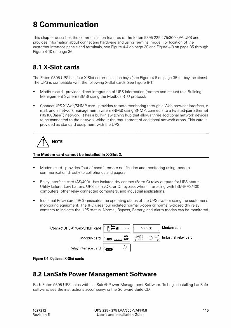
8 Communication
This chapter describes the communication features of the Eaton 9395 225-275/300 kVA UPS and provides information about connecting hardware and using Terminal mode. For location of the customer interface panels and terminals, see Figure 4-4 on page 30 and Figure 4-8 on page 35 through Figure 4-10 on page 36.
8.1 X-Slot cards
The Eaton 9395 UPS has four X-Slot communication bays (see Figure 4-8 on page 35 for bay locations). The UPS is compatible with the following X-Slot cards (see Figure 8-1):
• Modbus card - provides direct integration of UPS information (meters and status) to a Building Management System (BMS) using the Modbus RTU protocol.
• ConnectUPS-X Web/SNMP card - provides remote monitoring through a Web browser interface, e-mail, and a network management system (NMS) using SNMP; connects to a twisted-pair Ethernet (10/100BaseT) network. It has a built-in switching hub that allows three additional network devices to be connected to the network without the requirement of additional network drops. This card is provided as standard equipment with the UPS.
NOTE
The Modem card cannot be installed in X-Slot 2.
• Modem card - provides “out-of-band” remote notification and monitoring using modem communication directly to cell phones and pagers.
• Relay Interface card (AS/400) - has isolated dry contact (Form-C) relay outputs for UPS status: Utility failure, Low battery, UPS alarm/OK, or On bypass when interfacing with IBM® AS/400 computers, other relay connected computers, and industrial applications.
• Industrial Relay card (IRC) - indicates the operating status of the UPS system using the customer’s monitoring equipment. The IRC uses four isolated normally-open or normally-closed dry relay contacts to indicate the UPS status. Normal, Bypass, Battery, and Alarm modes can be monitored.
Figure 8-1. Optional X-Slot cards
8.2 LanSafe Power Management Software
Each Eaton 9395 UPS ships with LanSafe® Power Management Software. To begin installing LanSafe software, see the instructions accompanying the Software Suite CD.
1027212 UPS 225 - 275 kVA/300kVAPF0.8 115Revision E User’s and Installation Guide
LanSafe software uses an RS-232 serial link to communicate with the UPS. The software provides up-to-date graphics of UPS power and system data and power flow, a complete record of critical power events, and notification of important UPS or power information. With custom views for monitoring status and metering information, various user groups can select the most useful view for their specific needs. LanSafe Power Management Software
8.3 Terminal mode
Terminal mode is supported by all RS-232 serial communication ports of the UPS. The following settings should be used:
• Baud rate:19200
• 8 data bits
• no parity
• 1 stop bit
NOTE
The brackets ([ ]) in the following bullets indicate standard keyboard characters. To use a key
combination, hold down the Escape key and press the indicated letter key.
In Terminal mode, the user can request the following:
• [ESC] [A] displays the Active Alarms.
• [ESC] [H] displays the Event History.
• [ESC] [N] displays the Node Bits Setup.
• [ESC] [V] displays the UPS control panel.
• [ESC] [Q] Quit.
8.3.1 Display UPS control panel
When this function is invoked, a facsimile of the UPS control panel is displayed on the terminal screen. All controls are functional and can control the UPS remotely. The only exception is the Load Off control which requires the operator to press and hold the local control for three seconds to shut down the UPS.
To remotely control the UPS or view UPS information, use the escape key legend to control the function normally controlled by the control panel softkeys. See Section 7.2 on page 71 for instructions on navigating the control panel.
8.3.2 Event History Log
This key sequence prints the entire Event History Log of the UPS at the time the data is requested. The printout begins with the oldest alarm entry in the queue and ends with the most recent. Any alarms that occur while the Event History Log is printing are included in chronological order.
116 UPS 225 - 275 kVA/300kVAPF0.8 1027212User’s and Installation Guide Revision E
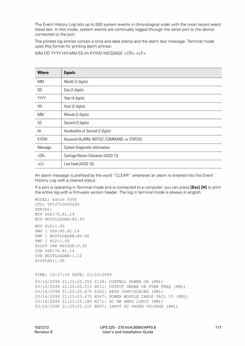
The Event History Log lists up to 500 system events in chronological order with the most recent event listed last. In this mode, system events are continually logged through the serial port to the device connected to the port.
The printed log entries contain a time and date stamp and the alarm text message. Terminal mode uses this format for printing alarm entries:
MM DD YYYY HH:MM:SS.hh KYWD MESSAGE <CR> <LF>
An alarm message is prefixed by the word “CLEAR” whenever an alarm is entered into the Event History Log with a cleared status.
If a port is operating in Terminal mode and is connected to a computer, you can press [Esc] [H] to print the entire log with a firmware version header. The log in terminal mode is always in english.
MODEL: Eaton 9395CTO: TF12710000000SERIAL:MCU DSP:70.81.14MCU BOOTLOADER:80.40
MCU PLD:1.00PMF 1 DSP:80.81.14PMF 1 BOOTLOADER:80.40PMF 1 PLD:1.00XSLOT CAN BRIDGE:0.00CSB DSP:70.81.14CSB BOOTLOADER:1.12DISPLAY:1.06
TIME: 19:17:16 DATE: 03/23/2099
03/16/2099 21:25:20.355 S138: CONTROL POWER ON (PM1)03/16/2099 21:25:20.515 N011: OUTPUT UNDER OR OVER FREQ (PM1)03/16/2099 21:25:20.675 S302: EEPS CONFIGURING (PM1)03/16/2099 21:25:23.475 N267: POWER MODULE CABLE FAIL 15 (PM1)03/16/2099 21:25:25.180 N271: DC HW AMPS LIMIT (PM1)03/16/2099 21:25:25.215 N007: INPUT AC UNDER VOLTAGE (PM1)
Where Equals
MM Month (2 digits)
DD Day (2 digits)
YYYY Year (4 digits)
HH Hour (2 digits)
MM Minute (2 digits)
SS Second (2 digits)
hh Hundredths of Second (2 digits)
KYDW Keyword (ALARM, NOTICE, COMMAND, or STATUS)
Message System Diagnostic Information
<CR> Carriage Return Character (ASCII 13)
<LF> Line Feed (ASCII 10)
1027212 UPS 225 - 275 kVA/300kVAPF0.8 117Revision E User’s and Installation Guide
03/16/2099 21:25:25.850 N011: OUTPUT UNDER OR OVER FREQ OK (PM1)...
03/23/2099 18:59:20.450 A199: BATTERIES DISCONNECTED (PM1)ACTIVE ALARMS:11 NOTICE: OUTPUT UNDER OR OVER FREQ (PM1)12 ALARM: REMOTE EMERGENCY POWER OFF (MCU)102 NOTICE: INVERTER L1 CURRENT LIMIT (PM1)103 NOTICE: INVERTER L2 CURRENT LIMIT (PM1)104 NOTICE: INVERTER L3 CURRENT LIMIT (PM1)
8.4 Building alarm monitoring
This standard feature lets you connect the UPS to your building alarms, such as smoke detectors or overtemperature alarms. The customer interface terminals for external connections are located inside the UPS. You should use twisted-pair wires for each alarm input and common.
The building alarms can be programmed to display the alarm functional name.
8.5 General purpose relay contact
One general purpose relay contact is provided as a standard feature on the UPS. The alarm contact is located inside the UPS on the customer interface terminal board.
You can use a normally-closed or normally-open contact. If the state of the contact changes from the state you specify as normal, a signal is issued. You can connect this contact to equipment at your facility (such as a light or an alarm bell) to let you know when an alarm is active on the UPS. This feature is useful if the UPS is located in a remote area where the UPS horn may not be heard immediately.
CAUTION
Contacts should not be operated in excess of 30 Vac @ 5A maximum.
118 UPS 225 - 275 kVA/300kVAPF0.8 1027212User’s and Installation Guide Revision E
9 UPS maintenance
The components inside the UPS cabinet are secured to a sturdy metal frame. All repairable parts and assemblies are located for easy removal, with very little disassembly. This design allows authorized service personnel to perform routine maintenance and servicing quickly.
You must schedule periodic performance checks of your UPS system to keep it running properly. Regular routine checks of operation and system parameters enable your system to function efficiently for many trouble-free years.
9.1 Important safety instructions
Remember that your UPS system is designed to supply power EVEN WHEN DISCONNECTED FROM THE UTILITY POWER. The UPS module interiors are unsafe until the DC power source is disconnected and the electrolytic capacitors are discharged. After disconnecting the utility power and the DC power, authorized service personnel should wait at least five minutes for capacitor bleedoff before attempting internal access to the UPS module.
WARNING
• Servicing and maintenance should be performed by qualified service personnel only.
• LETHAL VOLTAGE PRESENT. This unit should not be operated with the cabinet doors open
or protective panels removed. Do not make any assumptions about the electrical state of
any cabinet in the UPS system.
Since each battery string is an energy source in itself, opening the battery circuit breaker does not de-energize the voltage within the battery string. DO NOT ATTEMPT TO ACCESS ANY INTERNAL AREA OF THE BATTERY STRING YOURSELF. VOLTAGES ARE ALWAYS PRESENT IN THE BATTERY STRING. If you suspect that a battery string needs service, you should contact your service representative.
If the string requires service, refer to the battery manufacturer’s operating manual for instructions on battery maintenance or contact your service representative.
Observe these precautions when working on or around batteries:
• Remove watches, rings, or other metal objects.
• Use tools with insulated handles.
• Wear rubber gloves and boots.
• Do not lay tools or metal parts on top of batteries or battery cabinets.
• Disconnect the charging source prior to connecting or disconnecting terminals.
• Determine if the battery is inadvertently grounded. If it is, remove the source of the ground. Contact with any part of a grounded battery can result in electrical shock. The likelihood of such shock is reduced if such grounds are removed during installation and maintenance.
• When replacing batteries, use the same number of sealed, lead-acid batteries.
• Proper disposal of batteries is required. Refer to your local codes for disposal requirements.
1027212 UPS 225 - 275 kVA/300kVAPF0.8 119Revision E User’s and Installation Guide
9.2 Performing preventive maintenance
The UPS system requires very little preventive maintenance. However, the system should be inspected periodically to verify that the units are operating normally and that the batteries are in good condition.
9.2.1 DAILY maintenance
Perform the following steps daily:
1. Check the area surrounding the UPS system. Ensure the area is not cluttered, allowing free accessto the unit.
2. Ensure the air intakes (vents on the front doors) and exhaust opening (on top of the UPS cabinet sections) are not blocked.
3. Ensure the operating environment is within the parameters specified in Section 3.2.1 on page 11 and Chapter 10: “Product specifications”.
4. Ensure the UPS is in Normal mode (Normal status indicator is illuminated). If an alarm lamp is illuminated or the Normal status indicator is not illuminated, contact your service representative.
9.2.2 MONTHLY maintenance
Perform the following steps monthly:
1. Monitor system parameters as described in Section 7.2 on page 71.2. Check the air filters (located behind the front doors) and wash or replace as necessary. The left
(ISBM) filter size is 12”×20”×1” and the right (UPM) filter sizes are 19.5”×21.5”×0.5”. Contact your service representative for replacement filters. To remove the filters:
a. Open the front door latch and swing the doors open.b. Remove the filters from the cabinet-mounted studs.c. Push the new filters onto the cabinet-mounted studs until seated against the cabinet.d. Close the doors and secure the latch.
3. Record the check results and any corrective actions in a suitable log.
9.2.3 PERIODIC maintenance
Periodic inspections of the UPS should be made to determine if components, wiring, and connections exhibit evidence of overheating. Particular attention should be given to bolted connections. Maintenance procedures should specify that the bolted connections be retorqued to values listed in this manual (see Table 3-5 on page 17).
9.2.4 ANNUAL maintenance
Annual preventive maintenance should be performed only by authorized service personnel familiar with maintenance and servicing of the UPS system. Contact your service representative for more information about service offerings.
9.2.5 BATTERY maintenance
Contact your service representative for battery maintenance. Battery replacement and maintenance should be performed only by authorized service personnel.
120 UPS 225 - 275 kVA/300kVAPF0.8 1027212User’s and Installation Guide Revision E
9.3 Installing batteries
NOTE
There is no DC disconnect device within the UPS.
Install batteries in accordance with the battery and battery cabinet or battery rack manufacturer’s instructions.
9.4 Recycling the used UPS or batteries
Before scrapping UPS or its battery cabinet, the battery bank must be removed. Local requirements must be followed in battery recycling or discard. The removal of batteries is allowed only by authorised service personnel due to high energy and voltage.
Do not discard waste electrical or electronic equipment in the trash.For proper disposal, contact your local collecting/recycling/reuse or hazardous waste center and follow the local legislation.
These symbols indicate on a product:
Use proper local collecting centers meeting local legislation when handling waste of electrical and electronic equipment.
WARNING
HAZARDOUS MATERIALS. Batteries may contain HIGH VOLTAGES, and
CAUSTIC, TOXIC and FLAMMABLE substances. Batteries can injure or kill people
and damage equipment if used improperly. DO NOT DISCARD unwanted batteries
or battery material in the public waste disposal system. Follow ALL applicable,
local regulations for storage, handling and disposal of batteries and battery
materials.
9.5 Maintenance training
A basic training course, available from Eaton Corporation, gives you a competent working knowledge of the UPS system operation and teaches you how to perform first level corrective maintenance. For more information about training and other services, contact the Eaton Help Desk for Eaton products.
1027212 UPS 225 - 275 kVA/300kVAPF0.8 121Revision E User’s and Installation Guide
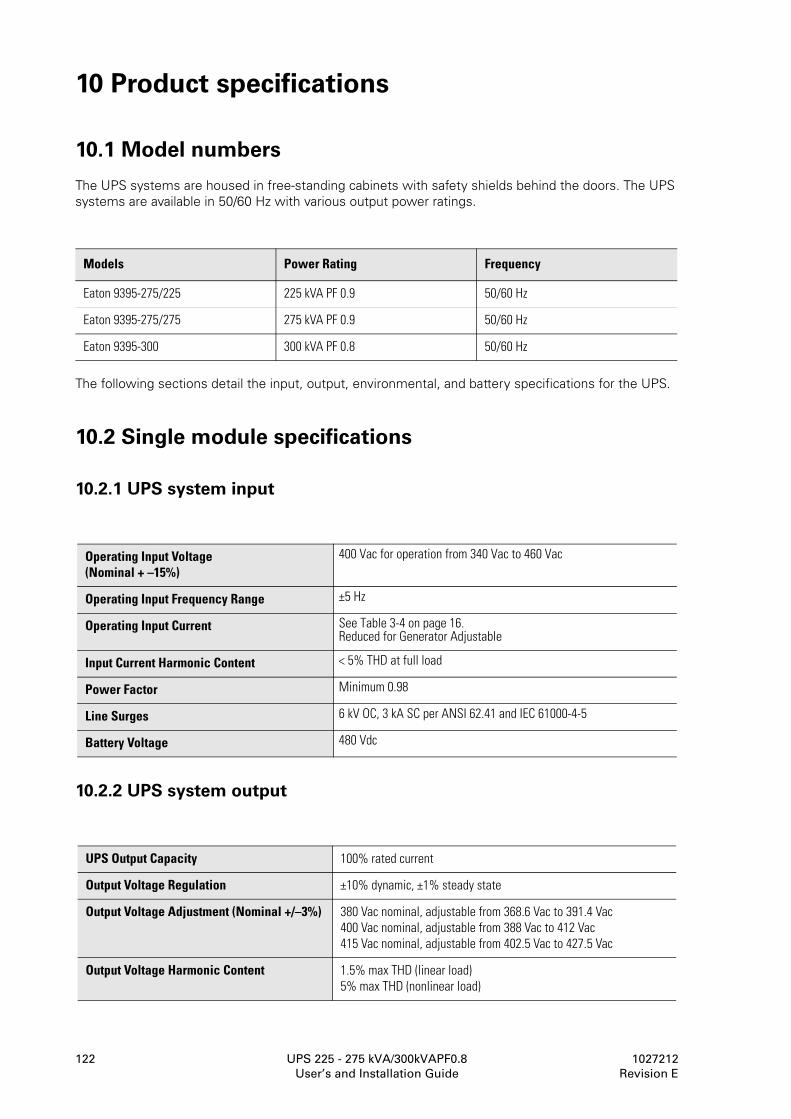
10 Product specifications
10.1 Model numbers
The UPS systems are housed in free-standing cabinets with safety shields behind the doors. The UPS systems are available in 50/60 Hz with various output power ratings.
The following sections detail the input, output, environmental, and battery specifications for the UPS.
10.2 Single module specifications
10.2.1 UPS system input
10.2.2 UPS system output
Models Power Rating Frequency
Eaton 9395-275/225 225 kVA PF 0.9 50/60 Hz
Eaton 9395-275/275 275 kVA PF 0.9 50/60 Hz
Eaton 9395-300 300 kVA PF 0.8 50/60 Hz
Operating Input Voltage(Nominal + –15%)
400 Vac for operation from 340 Vac to 460 Vac
Operating Input Frequency Range ±5 Hz
Operating Input Current See Table 3-4 on page 16.Reduced for Generator Adjustable
Input Current Harmonic Content < 5% THD at full load
Power Factor Minimum 0.98
Line Surges 6 kV OC, 3 kA SC per ANSI 62.41 and IEC 61000-4-5
Battery Voltage 480 Vdc
UPS Output Capacity 100% rated current
Output Voltage Regulation ±10% dynamic, ±1% steady state
Output Voltage Adjustment (Nominal +/–3%) 380 Vac nominal, adjustable from 368.6 Vac to 391.4 Vac400 Vac nominal, adjustable from 388 Vac to 412 Vac415 Vac nominal, adjustable from 402.5 Vac to 427.5 Vac
Output Voltage Harmonic Content 1.5% max THD (linear load)5% max THD (nonlinear load)
122 UPS 225 - 275 kVA/300kVAPF0.8 1027212User’s and Installation Guide Revision E
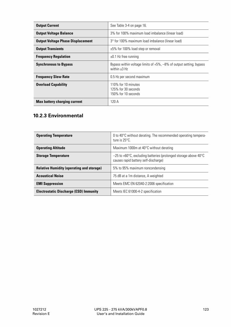
10.2.3 Environmental
Output Current See Table 3-4 on page 16.
Output Voltage Balance 3% for 100% maximum load imbalance (linear load)
Output Voltage Phase Displacement 3° for 100% maximum load imbalance (linear load)
Output Transients ±5% for 100% load step or removal
Frequency Regulation ±0.1 Hz free running
Synchronous to Bypass Bypass within voltage limits of +5%, –8% of output setting; bypass within ±3 Hz
Frequency Slew Rate 0.5 Hz per second maximum
Overload Capability 110% for 10 minutes125% for 30 seconds150% for 10 seconds
Max battery charging current 120 A
Operating Temperature 0 to 40°C without derating. The recommended operating tempera-ture is 25°C.
Operating Altitude Maximum 1000m at 40°C without derating
Storage Temperature –25 to +60°C, excluding batteries (prolonged storage above 40°C causes rapid battery self-discharge)
Relative Humidity (operating and storage) 5% to 95% maximum noncondensing
Acoustical Noise 75 dB at a 1m distance, A weighted
EMI Suppression Meets EMC EN 62040-2:2006 specification
Electrostatic Discharge (ESD) Immunity Meets IEC 61000-4-2 specification
1027212 UPS 225 - 275 kVA/300kVAPF0.8 123Revision E User’s and Installation Guide
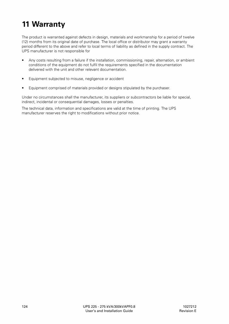
124 UPS 225 - 275 kVA/300kVAPF0.8 1027212User’s and Installation Guide Revision E
11 Warranty
The product is warranted against defects in design, materials and workmanship for a period of twelve (12) months from its original date of purchase. The local office or distributor may grant a warranty period different to the above and refer to local terms of liability as defined in the supply contract. The UPS manufacturer is not responsible for
• Any costs resulting from a failure if the installation, commissioning, repair, alternation, or ambient conditions of the equipment do not fulfil the requirements specified in the documentation delivered with the unit and other relevant documentation.
• Equipment subjected to misuse, negligence or accident
• Equipment comprised of materials provided or designs stipulated by the purchaser.
Under no circumstances shall the manufacturer, its suppliers or subcontractors be liable for special, indirect, incidental or consequential damages, losses or penalties.
The technical data, information and specifications are valid at the time of printing. The UPS manufacturer reserves the right to modifications without prior notice.
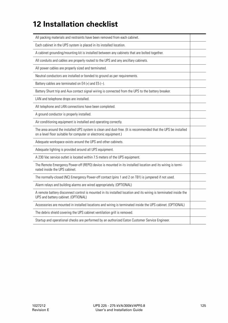
1027212 UPS 225 - 275 kVA/300kVAPF0.8 125Revision E User’s and Installation Guide
12 Installation checklist
All packing materials and restraints have been removed from each cabinet.
Each cabinet in the UPS system is placed in its installed location.
A cabinet grounding/mounting kit is installed between any cabinets that are bolted together.
All conduits and cables are properly routed to the UPS and any ancillary cabinets.
All power cables are properly sized and terminated.
Neutral conductors are installed or bonded to ground as per requirements.
Battery cables are terminated on E4 (+) and E5 (–).
Battery Shunt trip and Aux contact signal wiring is connected from the UPS to the battery breaker.
LAN and telephone drops are installed.
All telephone and LAN connections have been completed.
A ground conductor is properly installed.
Air conditioning equipment is installed and operating correctly.
The area around the installed UPS system is clean and dust-free. (It is recommended that the UPS be installed on a level floor suitable for computer or electronic equipment.)
Adequate workspace exists around the UPS and other cabinets.
Adequate lighting is provided around all UPS equipment.
A 230 Vac service outlet is located within 7.5 meters of the UPS equipment.
The Remote Emergency Power-off (REPO) device is mounted in its installed location and its wiring is termi-nated inside the UPS cabinet.
The normally-closed (NC) Emergency Power-off contact (pins 1 and 2 on TB1) is jumpered if not used.
Alarm relays and building alarms are wired appropriately. (OPTIONAL)
A remote battery disconnect control is mounted in its installed location and its wiring is terminated inside the UPS and battery cabinet. (OPTIONAL)
Accessories are mounted in installed locations and wiring is terminated inside the UPS cabinet. (OPTIONAL)
The debris shield covering the UPS cabinet ventilation grill is removed.
Startup and operational checks are performed by an authorized Eaton Customer Service Engineer.