Easy Cooling Row Chilled Water
44
Easy Cooling Row Chilled Water Operation and Maintenance ERC301BS1CGS, ERC301BD1CPS, ERC301BD1HPS, ERC601DS1CGS, ERC601DD1CPS, ERC601DD1HPS 12/2019 www.schneider-electric.com
Transcript of Easy Cooling Row Chilled Water

Easy Cooling Row Chilled WaterOperation and MaintenanceERC301BS1CGS, ERC301BD1CPS, ERC301BD1HPS, ERC601DS1CGS, ERC601DD1CPS,ERC601DD1HPS
12/2019
www.schneider-electric.com

Legal InformationThe Schneider Electric brand and any trademarks of Schneider Electric SE and itssubsidiaries referred to in this guide are the property of Schneider Electric SE or itssubsidiaries. All other brands may be trademarks of their respective owners.
This guide and its content are protected under applicable copyright laws andfurnished for informational use only. No part of this guide may be reproduced ortransmitted in any form or by any means (electronic, mechanical, photocopying,recording, or otherwise), for any purpose, without the prior written permission ofSchneider Electric.
Schneider Electric does not grant any right or license for commercial use of the guideor its content, except for a non-exclusive and personal license to consult it on an "asis" basis. Schneider Electric products and equipment should be installed, operated,serviced, and maintained only by qualified personnel.
As standards, specifications, and designs change from time to time, informationcontained in this guide may be subject to change without notice.
To the extent permitted by applicable law, no responsibility or liability is assumed bySchneider Electric and its subsidiaries for any errors or omissions in the informationalcontent of this material or consequences arising out of or resulting from the use of theinformation contained herein.

Table of Contents
Important Safety Instructions — SAVE THESEINSTRUCTIONS.........................................................................................5
Safety Precautions......................................................................................6Product Overview........................................................................................7
Benefits .....................................................................................................7
Commissioning............................................................................................8Inspection Checklists ..................................................................................8
Initial Inspection Checklist .....................................................................8Electrical Inspection Checklist................................................................8Mechanical Inspection Checklist ............................................................9Display Interface Inspection Checklist ....................................................9Start-Up Inspection Checklist ...............................................................10User Interface Checklist ......................................................................10Final Inspection Checklist ....................................................................10
Display Interface ....................................................................................... 11Communication Ports................................................................................12Using the Display......................................................................................12
Overview Screen ................................................................................12Main Menu Screen..............................................................................13Logging In/Password Entry ..................................................................13About .................................................................................................14
Operation Procedures ..............................................................................15Start Up the Cooling Unit...........................................................................15Shut Down the Cooling Unit.......................................................................15
Configure the Cooling Unit ......................................................................16Configure the Parameter Settings ..............................................................16Configure the Alarm Settings .....................................................................16Set the Configuration Settings ...................................................................17Configure the Control Parameter Settings...................................................18Configure the Network Settings .................................................................19Configure the Display Settings...................................................................19Change the PIN........................................................................................20
Configure the Service Settings ...............................................................21Configure the Control Parameter Settings...................................................21Reset the Run Hours ................................................................................21Configure the Sensors ..............................................................................22Configure the Group Control Settings.........................................................23Configure the Unit Features.......................................................................24Reset User Parameters to Factory Settings ................................................25Configure the Control Parameter Settings...................................................25Configure the Fan Settings ........................................................................27Configure the Water Valve Settings ............................................................28Configure the Alarm Settings .....................................................................28Configure the Switch Status Settings..........................................................30Configure the Manual Mode Settings..........................................................31Set the Maintenance Intervals ...................................................................31Reset the PIN...........................................................................................32
990-91304A-001 3

View the Operation Status.......................................................................33View Basic Status Information ...................................................................33View Detailed Status Information ...............................................................33View Group Status Information ..................................................................34View Active Alarms ...................................................................................34View Information on Run Hours .................................................................35View Temperature and Humidity Curve.......................................................35
Troubleshooting ........................................................................................36View the Log ............................................................................................36View the Data Log ....................................................................................36Perform a Firmware Update ......................................................................37Alarm List.................................................................................................38Troubleshooting and Recommended Actions ..............................................39
4 990-91304A-001

Important Safety Instructions — SAVE THESEINSTRUCTIONS
Important Safety Instructions — SAVE THESEINSTRUCTIONS
Read these instructions carefully and look at the equipment to become familiarwith it before trying to install, operate, service or maintain it. The following safetymessages may appear throughout this manual or on the equipment to warn ofpotential hazards or to call attention to information that clarifies or simplifies aprocedure.
The addition of this symbol to a “Danger” or “Warning” safetymessage indicates that an electrical hazard exists which will result inpersonal injury if the instructions are not followed.
This is the safety alert symbol. It is used to alert you to potentialpersonal injury hazards. Obey all safety messages with this symbolto avoid possible injury or death.
DANGERDANGER indicates a hazardous situation which, if not avoided, will result indeath or serious injury.
Failure to follow these instructions will result in death or serious injury.
WARNINGWARNING indicates a hazardous situation which, if not avoided, could resultin death or serious injury.
Failure to follow these instructions can result in death, serious injury, orequipment damage.
CAUTIONCAUTION indicates a hazardous situation which, if not avoided, could result inminor or moderate injury.
Failure to follow these instructions can result in injury or equipmentdamage.
NOTICENOTICE is used to address practices not related to physical injury. The safetyalert symbol shall not be used with this type of safety message.
Failure to follow these instructions can result in equipment damage.
Please NoteElectrical equipment should only be installed, operated, serviced, and maintainedby qualified personnel. No responsibility is assumed by Schneider Electric for anyconsequences arising out of the use of this material.
A qualified person is one who has skills and knowledge related to the construction,installation, and operation of electrical equipment and has received safety trainingto recognize and avoid the hazards involved.
990-91304A-001 5

Safety Precautions
Safety Precautions
DANGERHAZARD OF ELECTRIC SHOCK, EXPLOSION, OR ARC FLASH• The cooling unit must be installed, operated, serviced, and maintained only
by qualified personnel.• Apply appropriate personal protective equipment (PPE) and follow safe
electrical work practices.• Turn off all power supplying the cooling unit before working on the cooling
unit.• All electrical work must be performed by licensed electricians.• Follow lockout/tagout procedures.• Remove watches, rings, and other metal object before working on the
cooling unit.Failure to follow these instructions will result in death or serious injury.
WARNINGMOVING PARTS• Keep hands and clothing away from moving parts. Check the cooling unit for
foreign objects before closing the doors and starting up the cooling unit.• Do not remove rear panels during operation.Failure to follow these instructions can result in death, serious injury, orequipment damage.
WARNINGTIP HAZARD• Two persons are required for any movement of the cooling unit.• Always push, pull, or turn while facing the front and rear of this equipment.• Slowly move this equipment across uneven surfaces or door thresholds.• Lower the leveling feet when the equipment is at rest.• Lower the leveling feet and attach the joining brackets to adjacent racks
when the equipment is in its final position.Failure to follow these instructions can result in death, serious injury, orequipment damage.
6 990-91304A-001
Product Overview
Product OverviewThe Easy Cooling Row Chilled Water cooling unit can provide a cooling capacityof up to 30 kW based on a half-rack platform of 300 mm, whereas a full-rack of600 mm can provide a cooling capacity of up to 60 kW. An actuator works with thefans and a fin-tube exchanger to provide the best cooling efficiency.
This modular, row-based computer room cooling unit offers efficient, predictable,and value for money cooling. Critical environmental requirements reach farbeyond the confines of the traditional data center or computer room to encompassa larger suite of applications, referred to as technology rooms.
Critical environment applications include the following:• Computer rooms• Telecommunication facilities• Clean rooms• Power equipment• Medical equipment rooms• LAN/WAN environments
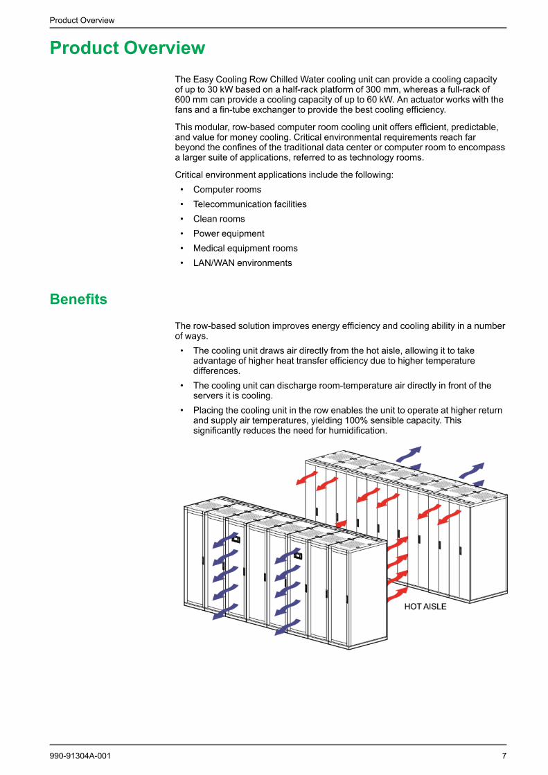
BenefitsThe row-based solution improves energy efficiency and cooling ability in a numberof ways.• The cooling unit draws air directly from the hot aisle, allowing it to take
advantage of higher heat transfer efficiency due to higher temperaturedifferences.
• The cooling unit can discharge room-temperature air directly in front of theservers it is cooling.
• Placing the cooling unit in the row enables the unit to operate at higher returnand supply air temperatures, yielding 100% sensible capacity. Thissignificantly reduces the need for humidification.
990-91304A-001 7

Commissioning
Commissioning
Inspection Checklists
Initial Inspection Checklist
WARNINGUNEXPECTED EQUIPMENT OPERATION
Do not route service equipment in front of the fans.
Failure to follow these instructions can result in death, serious injury, orequipment damage.
The initial inspection helps to ensure that the cooling unit has been properlyinstalled, the location of the cooling unit has been properly prepared, and thecooling unit is free of damage.
NOTE: The vapor barrier minimizes the moisture in filtration. Without a vaporbarrier, it is difficult to maintain the humidity in the room. Do not introduceunconditioned outside air into the space.
Make sure that the following checkpoints are adhered to:• The installation procedure is completed according to the requirements of the
installation manual and the local codes.• The walls, floor, and ceiling of the room, where the cooling unit is located, are
sealed with a vapor barrier.• There is no damage to the cooling unit.• The clearance around the cooling unit is in accordance with CE, local, and
national codes as well as the installation manual.• The cooling unit is leveled and interconnected with adjacent racks.• The cooling unit is not installed at the open end of a row.
Electrical Inspection Checklist
DANGERHAZARD OF ELECTRIC SHOCK, EXPLOSION, OR ARC FLASH• Apply appropriate personal protective equipment (PPE) and follow safe
electrical work practices.• All electrical work must be performed by licensed electricians.• Turn off all power supplying this cooling unit before working on the cooling
unit.• Install all devices, doors, and covers before turning on power to this cooling
unit.Failure to follow these instructions will result in death or serious injury.
WARNINGELECTRICAL HAZARD• Electrical service must conform to local and national electrical codes and
regulations.• The cooling unit must be grounded.Failure to follow these instructions can result in death, serious injury, orequipment damage.
8 990-91304A-001

Commissioning
The electrical inspection verifies that all electrical connections are correct and thatthe cooling unit is properly grounded.
Make sure that the following checkpoints are adhered to:• Incoming voltages match the phase and voltage rating on the nameplate.• Electrical wiring complies with local and national codes and regulations.• The cooling unit is properly earthed.• Front and rear doors are properly grounded.• Internal electrical components and terminal blocks do not have any loose
connections.• Electrical connections are tight, including contactors, terminal blocks,
controllers, switches, relays, auxiliary devices, and field connections.• The input and bypass (if applicable) sources are properly connected.• The circuit breakers are suitable and properly attached to the DIN rail.• The rack temperature sensors are installed correctly for the cooling unit.• The optional rope water detection device is installed correctly.• The temperature and humidity sensors are connected correctly.
Mechanical Inspection Checklist
CAUTIONPERSONAL INJURYAND EQUIPMENT DAMAGE• The cooling unit is shipped with a nitrogen holding charge. Remove the
nitrogen holding charge using the service ports located on the internalrefrigerant piping.
• Improperly installed piping may result in improper operation and possibledamage to the cooling unit or surrounding equipment.
Failure to follow these instructions can result in injury or equipmentdamage.
The mechanical inspection verifies that all mechanical components andconnections are tight and ready for start-up. The inspection helps to ensure thatthe field piping is installed correctly.
Make sure that the following checkpoints are adhered to:• The condensate drain line is the size of the drain connection and has proper
slope away from the cooling unit.• The mechanical connections are tight, including the refrigerant piping and the
condensate drain line.• Vertical, horizontal, and total lengths are recorded for liquid and gas lines.• Field-installed trap sand piping are in accordance with the installation manual
and follow proper piping practices.• The number of 45- and 90-degree bends in the refrigerant piping are
recorded.• The room conditions comply with the operating guidelines. Covers and
guards are in place.• Piping is adequately supported and isolated where necessary.• Piping in the building and on the roof is insulated adequately.• Piping has been leak tested.
Display Interface Inspection Checklist
The display interface inspection verifies that the sensor and internalcommunication links are installed correctly.
990-91304A-001 9
Commissioning
Make sure that the following checkpoints are adhered to:• The cooling unit is connected to the other cooling units in the room if cooling
group controls are used.• The input contacts and output relays are connected correctly.• The building management system is connected correctly and a terminator is
wired into the final cooling unit correctly.• The network port is connected correctly and a communication address has
been assigned to the cooling unit.
Start-Up Inspection Checklist
The start-up inspection helps to ensure that the equipment is operating correctlyafter the initial start-up. This inspection verifies that all modes of operation areworking correctly and that the cooling unit is ready for normal operation.
While the cooling unit is operating, make sure that the following checkpoints areadhered to:• The cooling unit is free from malfunctions, including water leaks, unusual
vibrations, or other irregularities in each mode of operation.• The cooling unit has the proper refrigerant charge for year-round operation.• The air filters are clean and free of debris. Replace air filters if necessary.• If applicable, air balance is done to verify that the fans are set to the desired
fan speed.• The temperature and humidity sensors are working correctly.
User Interface Checklist
User interface checks are done to verify that the cooling unit sensors and theinterior communication connections are in good working condition.
Verify that:• RS485 communication connections between all the cooling units are correct.• The input contact and the output relay connections are correct.• The building management system connections are correct. If Remote
communication control function is displayed on the screen, selectMODBUS. The baud rate is 9600.
• In group control function, the group mode of each cooling unit is set to GroupControl, and the IP address does not conflict.
Final Inspection Checklist
The final inspection verifies that the system is clean, the installed options workcorrectly, and the start-up form is sent to Schneider Electric.
Make sure that the following checkpoints are adhered to:• Interior and exterior of the cooling unit are clean and free from debris and
loose hardware.• Internal protective covers and hardware are installed.• Packaging materials are disposed off correctly.• There are no active alarms.• The user is trained to use the user display and is able to view active alarms
and status readings.• The user is given the technical support contact number that is applicable for
their region.• The user is given the unit documentation.• Start-up form is filled in and sent to Schneider Electric.
10 990-91304A-001
Display Interface
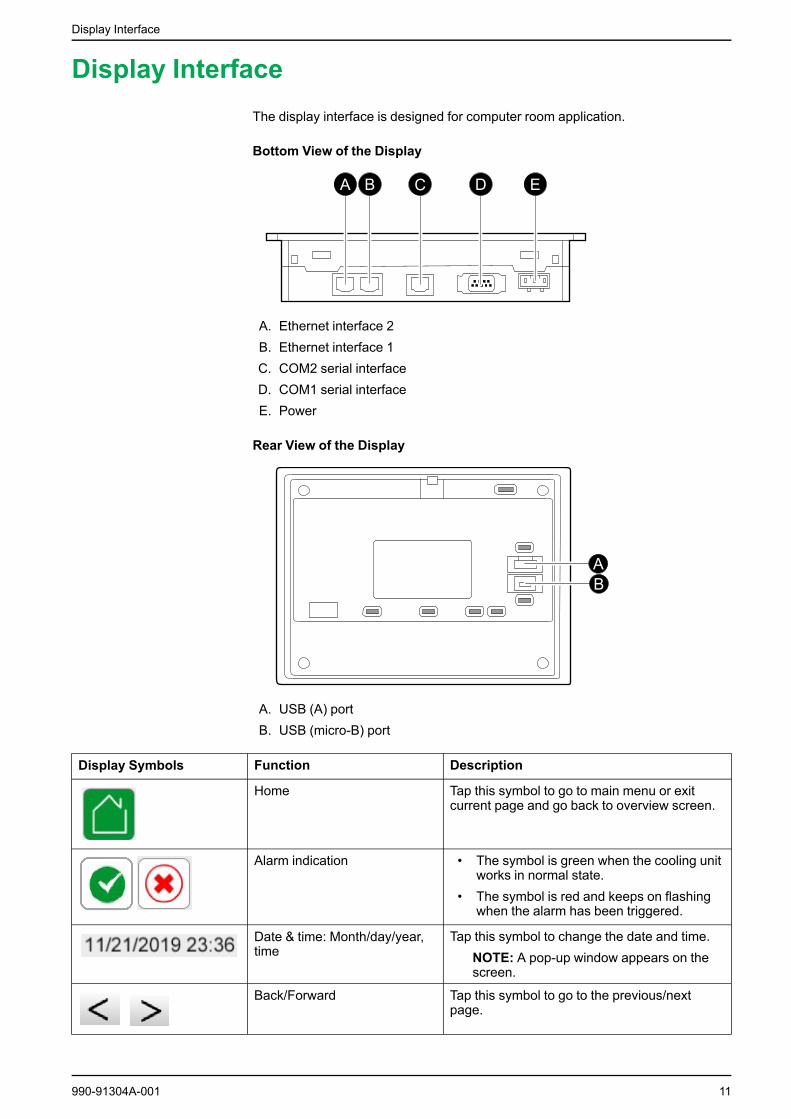
Display InterfaceThe display interface is designed for computer room application.
Bottom View of the Display
A. Ethernet interface 2B. Ethernet interface 1C. COM2 serial interfaceD. COM1 serial interfaceE. Power
Rear View of the Display
A. USB (A) portB. USB (micro-B) port
Display Symbols Function Description
Home Tap this symbol to go to main menu or exitcurrent page and go back to overview screen.
Alarm indication • The symbol is green when the cooling unitworks in normal state.
• The symbol is red and keeps on flashingwhen the alarm has been triggered.
Date & time: Month/day/year,time
Tap this symbol to change the date and time.NOTE: A pop-up window appears on thescreen.
Back/Forward Tap this symbol to go to the previous/nextpage.
990-91304A-001 11

Display Interface
Display Symbols Function Description
First/Last Tap this symbol to turn to the first page or lastpage.
Confirmation Tap this symbol to confirm selection or displayvalue.
Exit Tap this symbol to exit without accepting theparameter changes.
Communication Ports
Label Parameter Description Connection
COM1,COM2 Main control boardcommunication port
Main control boardcommunication
RS-485
RS-232C
USB Data interface Software upgrade USB
Using the DisplayWhen power is applied to the cooling unit, the control system initializes and thedisplay starts up.
Overview Screen
After start-up, the display shows an overview screen containing basic status
information. Tap to go to the main menu screen. After a period of inactivity, thedisplay reverts to the overview screen.
12 990-91304A-001
Display Interface
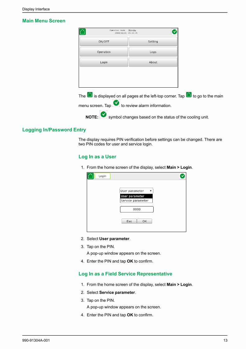
Main Menu Screen
The is displayed on all pages at the left-top corner. Tap to go to the main
menu screen. Tap to review alarm information.
NOTE: symbol changes based on the status of the cooling unit.
Logging In/Password Entry
The display requires PIN verification before settings can be changed. There aretwo PIN codes for user and service login.
Log In as a User
1. From the home screen of the display, select Main > Login.
2. Select User parameter.
3. Tap on the PIN.A pop-up window appears on the screen.
4. Enter the PIN and tap OK to confirm.
Log In as a Field Service Representative
1. From the home screen of the display, select Main > Login.
2. Select Service parameter.
3. Tap on the PIN.A pop-up window appears on the screen.
4. Enter the PIN and tap OK to confirm.
990-91304A-001 13

Display Interface
About
From the home screen of the display, select Main > About.
In the About page, information about the model and software version of thecooling unit is available.
NOTE: The above image is a typical sample. The actual cooling unit mayshow different information.
14 990-91304A-001

Operation Procedures
Operation Procedures
Start Up the Cooling Unit
1. From the home screen of the display, select Main > ON/OFF.
2. Tap ON.A pop-up window appears on the screen.
3. Tap OK to confirm start up of the cooling unit.
Shut Down the Cooling Unit
DANGERHAZARD OF ELECTRIC SHOCK, EXPLOSION, OR ARC FLASH
The Off option does not completely remove power from the cooling unit.Disconnect the input and bypass (if available) sources to completely removepower from the cooling unit.
Failure to follow these instructions will result in death or serious injury.
1. From the home screen of the display, select Main > ON/OFF
2. Tap OFF.A pop-up window appears on the screen.
3. Tap OK to confirm power off of the cooling unit.
990-91304A-001 15

Configure the Cooling Unit
Configure the Cooling Unit
Configure the Parameter Settings
1. From the home screen of the display, select Main > Setting > User >Parameter settings.
2. Set the Supply air setpoint. Choose a value between 5 and 50℃ and tapOK to save the settings. The default value is 22 °C.
3. Set the Return air setpoint. Choose a value between 5 and 50℃ and tapOK to save the settings. The default value is 35 °C.
4. Set the Rack inlet setpoint. Choose a value between 5 and 50℃ and tapOK to save the settings. The default value is 22 °C.
5. Set the Supply and return air temperature difference. Choose a valuebetween 0 and 25℃ and tap OK to save the settings. The default value is 13°C.
6. Set the Return air humidity setpoint. Choose a value between 10 and 95%and tap OK to save the settings. The default value is 25%.
7. Set the Startup delay. Choose a value between 0 and 240 seconds and tapOK to save the settings. The default value is 2.
Configure the Alarm Settings
1. From the home screen of the display, select Main > Setting > User > Alarmthresholds.
2. Set the Return air high temperature threshold. Choose a value between 10and 50℃ and tap OK to save the settings.
16 990-91304A-001

Configure the Cooling Unit
3. Set the Return air low temperature threshold. Choose a value between 0and 40℃ and tap OK to save the settings.
4. Set the Supply air high temperature threshold. Choose a value between 1and 35℃ and tap OK to save the settings.
5. Set the Supply air low temperature threshold. Choose a value between 1and 30℃ and tap OK to save the settings.
6. Set the Rack inlet high temperature threshold. Choose a value between 1and 35℃ and tap OK to save the settings.
7. Set the Rack inlet low temperature threshold. Choose a value between 1and 30℃ and tap OK to save the settings.
8. Set the Room high humidity threshold. Choose a value between 10 and95% and tap OK to save the settings.
9. Set the Room low humidity threshold. Choose a value between 10 and95% and tap OK to save the settings.
10. Set the Chilled water inlet high temperature threshold. Choose a valuebetween 0 and 30℃ and tap OK to save the settings.
11. Set the Chilled water inlet low temperature threshold. Choose a valuebetween 0 and 30℃ and tap OK to save the settings.
12. Set the Chilled water outlet high temperature threshold. Choose a valuebetween 0 and 30℃ and tap OK to save the settings.
13. Set the Chilled water outlet low temperature threshold. Choose a valuebetween 0 and 30℃ and tap OK to save the settings.
14. Set the Chilled water inlet low pressure threshold. Choose a valuebetween 0 and 5 bar and tap OK to save the settings.
Set the Configuration Settings
1. From the home screen of the display, select Main > Setting > User >Configuration.
2. Set the Rack inlet temperature 1 to Enable or Disable as per therequirement and tap OK to save the settings.
3. Set the Rack inlet temperature 2 to Enable or Disable as per therequirement and tap OK to save the settings.
4. Set the Rack inlet temperature 3 to Enable or Disable as per therequirement and tap OK to save the settings.
5. Set the Leak detection alarm to Enable or Disable as per the requirementand tap OK to save the settings.
990-91304A-001 17
Configure the Cooling Unit
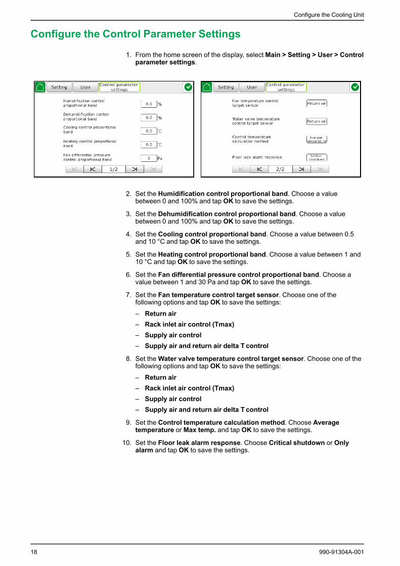
Configure the Control Parameter Settings
1. From the home screen of the display, select Main > Setting > User > Controlparameter settings.
2. Set the Humidification control proportional band. Choose a valuebetween 0 and 100% and tap OK to save the settings.
3. Set the Dehumidification control proportional band. Choose a valuebetween 0 and 100% and tap OK to save the settings.
4. Set the Cooling control proportional band. Choose a value between 0.5and 10 °C and tap OK to save the settings.
5. Set the Heating control proportional band. Choose a value between 1 and10 °C and tap OK to save the settings.
6. Set the Fan differential pressure control proportional band. Choose avalue between 1 and 30 Pa and tap OK to save the settings.
7. Set the Fan temperature control target sensor. Choose one of thefollowing options and tap OK to save the settings:
– Return air– Rack inlet air control (Tmax)– Supply air control– Supply air and return air delta T control
8. Set theWater valve temperature control target sensor. Choose one of thefollowing options and tap OK to save the settings:
– Return air– Rack inlet air control (Tmax)– Supply air control– Supply air and return air delta T control
9. Set the Control temperature calculation method. Choose Averagetemperature orMax temp. and tap OK to save the settings.
10. Set the Floor leak alarm response. Choose Critical shutdown or Onlyalarm and tap OK to save the settings.
18 990-91304A-001

Configure the Cooling Unit
Configure the Network Settings
1. From the home screen of the display, select Main > Setting > User >Network.
2. Set the Remote communication control option. Choose one of the followingoptions and tap OK to save the settings:
– Disable– Modbus– YDT
3. Set the Remote communication address. Choose a value between 1 and240 and tap OK to save the settings.
4. Set the Remote communication inoperable delay. Choose a valuebetween 0 and 10 min and tap OK to save the settings.
5. Set the Remote communication baud rate. Choose a value between 0 and5 and tap OK to save the settings.
Configure the Display Settings
1. From the home screen of the display, select Main > Setting > User >Display.
2. Tap on the Date/Time button and set the time.
3. Set the Buzzer to Enable or Disable (default is Enable).
4. Tap the + and - buttons to set the brightness of the display.
990-91304A-001 19

Configure the Cooling Unit
Change the PIN
1. From the home screen of the display, select Main > Setting > User >Change PIN.
2. Type in the Original PIN.
3. Type in the New PIN.
4. Confirm the new PIN.
5. Tap OK to save the settings.
20 990-91304A-001
Configure the Service Settings
Configure the Service Settings
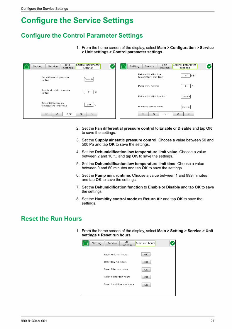
Configure the Control Parameter Settings
1. From the home screen of the display, select Main > Configuration > Service> Unit settings > Control parameter settings.
2. Set the Fan differential pressure control to Enable or Disable and tap OKto save the settings.
3. Set the Supply air static pressure control. Choose a value between 50 and500 Pa and tap OK to save the settings.
4. Set the Dehumidification low temperature limit value. Choose a valuebetween 2 and 10℃ and tap OK to save the settings.
5. Set the Dehumidification low temperature limit time. Choose a valuebetween 0 and 60 minutes and tap OK to save the settings.
6. Set the Pump min. runtime. Choose a value between 1 and 999 minutesand tap OK to save the settings.
7. Set the Dehumidification function to Enable or Disable and tap OK to savethe settings.
8. Set the Humidity control mode as Return Air and tap OK to save thesettings.
Reset the Run Hours
1. From the home screen of the display, select Main > Setting > Service > Unitsettings > Reset run hours.
990-91304A-001 21
Configure the Service Settings
2. Tap OK for each part below to reset the run hours.
a. Reset the unit run hours.
b. Reset the fan run hours.
c. Reset the filter run hours.
d. Reset the heater run hours.
e. Reset the humidifier run hours.
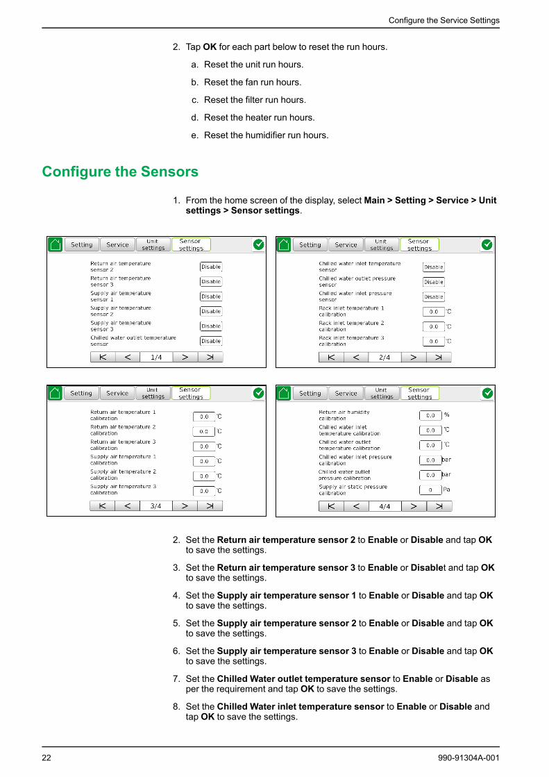
Configure the Sensors
1. From the home screen of the display, select Main > Setting > Service > Unitsettings > Sensor settings.
2. Set the Return air temperature sensor 2 to Enable or Disable and tap OKto save the settings.
3. Set the Return air temperature sensor 3 to Enable or Disablet and tap OKto save the settings.
4. Set the Supply air temperature sensor 1 to Enable or Disable and tap OKto save the settings.
5. Set the Supply air temperature sensor 2 to Enable or Disable and tap OKto save the settings.
6. Set the Supply air temperature sensor 3 to Enable or Disable and tap OKto save the settings.
7. Set the Chilled Water outlet temperature sensor to Enable or Disable asper the requirement and tap OK to save the settings.
8. Set the Chilled Water inlet temperature sensor to Enable or Disable andtap OK to save the settings.
22 990-91304A-001

Configure the Service Settings
9. Set the Chilled water outlet pressure sensor to Enable or Disable and tapOK to save the settings.
10. Set the Chilled water inlet pressure sensor to Enable or Disable and tapOK to save the settings.
11. Set the Rack inlet temperature 1 calibration. Choose a value between -9.9and 9.9℃ and tap OK to save the settings.
12. Set the Rack inlet temperature 2 calibration. Choose a value between -9.9and 9.9℃ and tap OK to save the settings.
13. Set the Rack inlet temperature 3 calibration. Choose a value between -9.9and 9.9℃ and tap OK to save the settings.
14. Set the Return air temperature 1 calibration. Choose a value between -9.9and 9.9℃ and tap OK to save the settings.
15. Set the Return air temperature 2 calibration. Choose a value between -9.9and 9.9℃ and tap OK to save the settings.
16. Set the Supply air temperature 1 calibration. Choose a value between -9.9and 9.9℃ and tap OK to save the settings.
17. Set the Supply air temperature 2 calibration. Choose a value between -9.9and 9.9℃ and tap OK to save the settings.
18. Set the Supply air temperature 3 calibration. Choose a value between -9.9and 9.9℃ and tap OK to save the settings.
19. Set the Supply air humidity calibration. Choose a value between -30 and30% and tap OK to save the settings.
20. Set the Chilled water inlet temperature calibration. Choose a valuebetween -9.9 and 9.9℃ and tap OK to save the settings.
21. Set the Chilled water outlet temperature calibration. Choose a valuebetween -9.9 and 9.9℃ and tap OK to save the settings.
22. Set the Chilled water inlet pressure calibration. Choose a value between-9.9 and 9.9℃ and tap OK to save the settings.
23. Set the Chilled water outlet pressure calibration. Choose a value between-9.9 and 9.9℃ and tap OK to save the settings.
24. Set the Supply air static pressure calibration. Choose a value between -30and 30 Pa and tap OK to save the settings.
Configure the Group Control Settings
1. From the home screen of the display, select Main > Setting > Service >Group control settings.
2. Set the Local communication address. Choose a value between 0 and 31and tap OK to save the settings.
990-91304A-001 23

Configure the Service Settings
3. Set the Group control. Choose Single unit or Group control and tap OK tosave the settings.
4. Set the Number of units in group. Choose a value between 0 and 32 andtap OK to save the settings.
5. Set the Number of standby units in group. Choose a value between 0 and31 and tap OK to save the settings.
6. Set the Unit rotation mode. Choose By online time or By address and tapOK to save the settings.
7. Set the Unit rotation period. Choose a value between 1 and 240 hours andtap OK to save the settings.
8. Set the Group control parameter type. Choose one of the following optionsand tap OK to save the settings:
– Host– Slave– Slave average
Configure the Unit Features
1. From the home screen of the display, select Main > Setting > Service > Unitfeatures.
2. Set the Unit model and tap OK to save the settings.The model number of the cooling unit is available in the About page.
3. Set theModel number suffix and tap OK to save the settings.The model suffix supplement number of the cooling unit is available in theAbout page.
4. Enter serial number and tap OK to save the settings.The serial number of the cooling unit is available in the About page.
5. Set the Humidifier type. Choose one of the following options and tap OK tosave the settings:
– Disable– Electrode humidifier
6. Set the Heater type. Choose one of the following options and tap OK to savethe settings:
– Disable– 1– 2
24 990-91304A-001
Configure the Service Settings
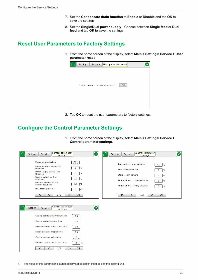
7. Set the Condensate drain function to Enable or Disable and tap OK tosave the settings.
8. Set the Single/Dual power supply1. Choose between Single feed or Dualfeed and tap OK to save the settings.
Reset User Parameters to Factory Settings
1. From the home screen of the display, select Main > Setting > Service > Userparameter reset.
2. Tap OK to reset the user parameters to factory settings.
Configure the Control Parameter Settings
1. From the home screen of the display, select Main > Setting > Service >Control parameter settings.
990-91304A-001 25
1. The value of this parameter is automatically set based on the model of the cooling unit.

Configure the Service Settings
2. Set the Power input selection. Choose Single phase or Three phase andtap OK to save the settings.
3. Set the Power supply undervoltage threshold2. Choose a value between150 and 300 V and tap OK to save the settings.
4. Set the Power supply overvoltage threshold2. Choose a value between150 and 300 V and tap OK to save the settings.
5. Set the Cooling output control deadband. Choose a value between 0.5 and5 °C and tap OK to save the settings.
6. Set the Dehumidification output control deadband. Choose a valuebetween 0 and 10% and tap OK to save the settings.
7. Set theMin. cooling runtime. Choose a value between 1 and 30 minutesand tap OK to save the settings.
8. Set the Temperature corrected value3. Choose a value between 0 and 5 °Cand tap OK to save the settings.
9. Set the Stop cooling demand. Choose a value between –100 and 0% andtap OK to save the settings.
10. Set the Start cooling demand. Choose a value between 0 and 100% and tapOK to save the settings.
11. Set the Airflow at max. cooling capacity. Choose a value between 1 and100% and tap OK to save the settings.
12. Set the Airflow at min. cooling capacity. Choose a value between 0 and100% and tap OK to save the settings.
13. Set the Cooling control proportional band. Choose a value between 1 and100 and tap OK to save the settings.
14. Set the Cooling control integral time. Choose a value between 0 and 100and tap OK to save the settings.
15. Set the Heating control proportional band. Choose a value between 1 and100 and tap OK to save the settings.
16. Set the Heating control integral time. Choose a value between 0 and 100and tap OK to save the settings.
17. Set the Cooling demand calculation. Choose P or PI and tap OK to savethe settings.
18. Set the Demand control calculation cycle. Choose a value between 5 and600 seconds and tap OK to save the settings.
26 990-91304A-001
2. Power supply undervoltage/overvoltage is for single power supply.3. Actual temp. setting control value = Supply air temp. settings (display value) - temp. corrected value.

Configure the Service Settings
Configure the Fan Settings
1. From the home screen of the display, select Main > Configuration > Service> Fan settings.
2. Set the Fan type. Choose EC FAN and tap OK to save the settings.
3. Set the Dehumidification fan speed and tap OK to save the settings.
4. Set the Number of fans and tap OK to save the settings.
5. Set Fan start delay. Choose a value between 1 and 255 seconds and tap OKto save the settings.
6. Set Fan off delay. Choose a value between 1 and 255 seconds and tap OKto save the settings.
7. Set the Fan rated speed. Choose a value between 0 and 100% and tap OKto save the settings.
8. Set theMin. fan speed. Choose a value between 0 and 100% and tap OK tosave the settings.
9. Set the Fan model. Choose between RH22V and RH35V and tap OK to savethe settings.
10. Set the Fan speed control step. Choose a value between 1 and 10% andtap OK to save the settings.
11. Set the Fan start-up and maintenance interval. Choose a value between 0and 600 seconds and tap OK to save the settings.
12. Set the Fan speed control ratio. Choose a value between 1 and 10 and tapOK to save the settings.
13. Set the EC fan pulse number per revolution. Choose a value between 1and 20 and tap OK to save the settings.
14. Set the Dehumidification air pressure differential. Choose a valuebetween 1 and 100% and tap OK to save the settings.
15. Set the Heater startup delay. Choose a value between 1 and 10 minutesand tap OK to save the settings.
990-91304A-001 27

Configure the Service Settings
Configure the Water Valve Settings
1. From the home screen of the display, select Main > Setting > Service >Water valve settings.
2. Set the Chilled water valve max. opening. Choose a value betweenminimum setting and 100% and tap OK to save the settings. Default value is100.
3. Set the Chilled water valve min. opening. Choose a value between 0% andthe maximum setting and tap OK to save the settings. Default value is 10.
4. Set the Chilled water valve speed control ratio. Choose a value between 0and 10 and tap OK to save the settings. Default value is 10.
5. Set the Chilled water valve speed control step. Choose a value between 1and 100% per second and tap OK to save the settings. Default value is 1.
Configure the Alarm Settings
1. From the home screen of the display, select Main > Setting > Service >Alarm setting.
28 990-91304A-001

Configure the Service Settings
2. Set the Fan alarm. Choose one of the following options and tap OK to savethe settings:
– Disable. If this option is selected, the alarm will not be triggered when thefan is inoperable.
– Check overload/air flow. If this option is selected, the fan overload alarmwill be triggered when the fan is inoperable.
– Check feedback/air flow. If this option is selected, the fan feedbackalarm will be triggered when the fan is inoperable.
• For the 300 mm wide cooling units, the default alarm setting is Checkfeedback/air flow.
• For the 600 mm wide cooling units, the default alarm setting is Checkoverload/air flow.
3. Set the Power supply missing phase alarm to Enable or Disable and tapOK to save the settings.
4. Set the Overvoltage/undervoltage alarm to Enable or Disable and tap OKto save the settings.
5. Set the Line A power supply alarm to Enable or Disable and tap OK tosave the settings.
6. Set the Line B power supply alarm to Enable or Disable and tap OK tosave the settings.
7. Set the Rack inlet high temperature alarm to Enable or Disable and tapOK to save the settings.
8. Set the Rack inlet low temperature alarm to Enable or Disable and tap OKto save the settings.
9. Set the Heater high temperature alarm to Enable or Disable and tap OK tosave the settings.
10. Set the Smoke detection alarm to Enable or Disable and tap OK to savethe settings.
11. Set the Filter clogged alarm to Enable or Disable and tap OK to save thesettings.
12. Set the Humidification inoperable alarm to Enable or Disable and tap OKto save the settings.
13. Set the Chilled water inlet low pressure alarm to Enable or Disable andtap OK to save the settings.
14. Set the Return air high temperature alarm to Enable or Disable and tapOK to save the settings.
15. Set the Return air low temperature alarm to Enable or Disable and tap OKto save the settings.
16. Set the Supply air high temperature alarm to Enable or Disable and tapOK to save the settings.
17. Set the Supply air low temperature alarm to Enable or Disable and tap OKto save the settings.
18. Set the High humidity alarm to Enable or Disable and tap OK to save thesettings.
19. Set the Low humidity alarm to Enable or Disable and tap OK to save thesettings.
20. Set the Chilled water inlet high temperature alarm to Enable or Disableand tap OK to save the settings.
21. Set the Chilled water inlet low temperature alarm to Enable or Disableand tap OK to save the settings.
990-91304A-001 29

Configure the Service Settings
22. Set the Chilled water outlet water high temperature alarm to Enable orDisable and tap OK to save the settings.
23. Set the Chilled water outlet water low temperature alarm to Enable orDisable and tap OK to save the settings.
Configure the Switch Status Settings
1. From the home screen of the display, select Main > Setting > Service >Switch status settings.
NOTICEINOPERABLE EQUIPMENT
Only qualified service personnel must make changes to these settings.
Failure to follow these instructions can result in equipment damage.
2. Set the Fan alarm switch status. Choose Normally open or Normallyclosed and tap OK to save the settings.
3. Set the Filter clogged switch status. Choose Normally open or Normallyclosed and tap OK to save the settings.
4. Set the Heater alarm switch status. Choose Normally open or Normallyclosed and tap OK to save the settings.
5. Set the Smoke alarm switch status. Choose Normally open or Normallyclosed and tap OK to save the settings.
6. Set the Remote shutdown switch status. Choose Normally open orNormally closed and tap OK to save the settings.
7. Set the Floor leaking switch status. Choose Normally open or Normallyclosed and tap OK to save the settings.
8. Set the Humidification alarm switch status. Choose Normally open orNormally closed and tap OK to save the settings.
9. Set the Condensate high level switch status. Choose Normally open orNormally closed and tap OK to save the settings.
30 990-91304A-001
Configure the Service Settings
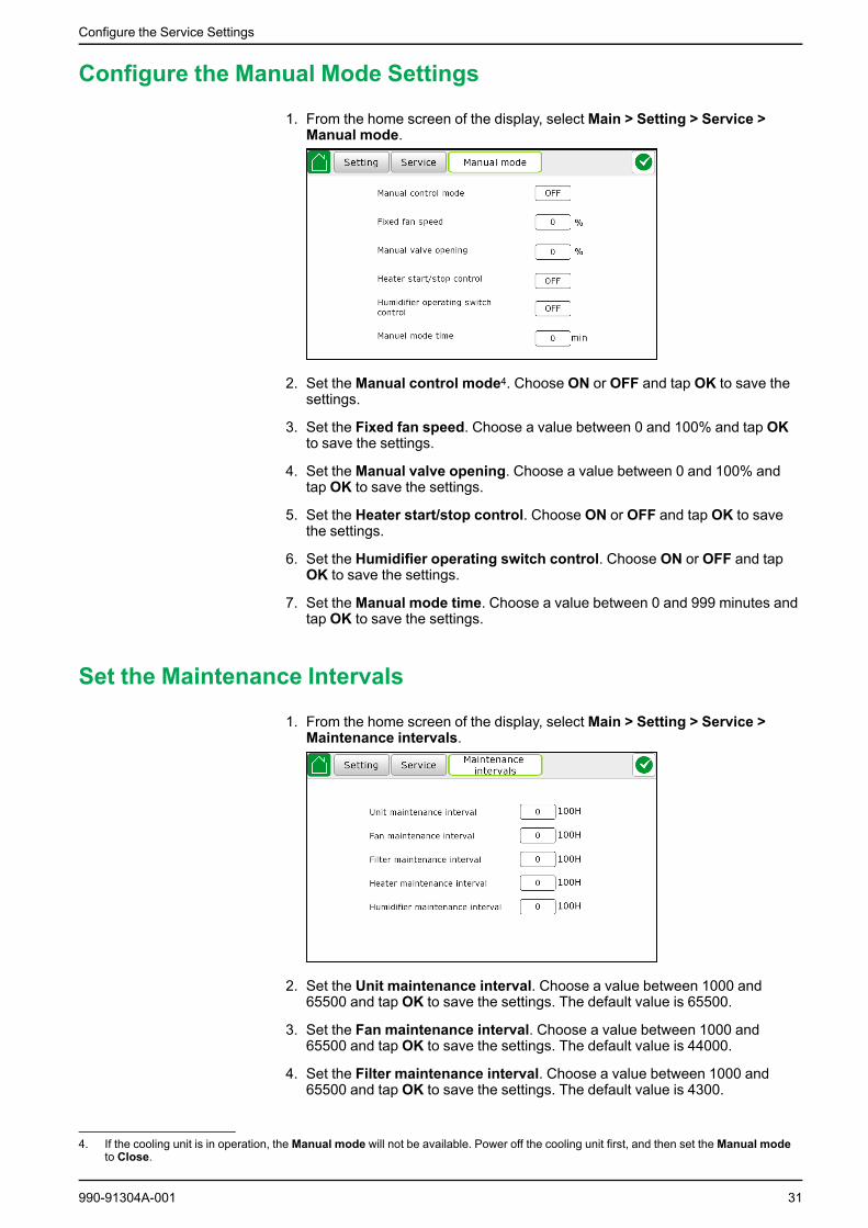
Configure the Manual Mode Settings
1. From the home screen of the display, select Main > Setting > Service >Manual mode.
2. Set theManual control mode4. Choose ON or OFF and tap OK to save thesettings.
3. Set the Fixed fan speed. Choose a value between 0 and 100% and tap OKto save the settings.
4. Set theManual valve opening. Choose a value between 0 and 100% andtap OK to save the settings.
5. Set the Heater start/stop control. Choose ON or OFF and tap OK to savethe settings.
6. Set the Humidifier operating switch control. Choose ON or OFF and tapOK to save the settings.
7. Set theManual mode time. Choose a value between 0 and 999 minutes andtap OK to save the settings.
Set the Maintenance Intervals
1. From the home screen of the display, select Main > Setting > Service >Maintenance intervals.
2. Set the Unit maintenance interval. Choose a value between 1000 and65500 and tap OK to save the settings. The default value is 65500.
3. Set the Fan maintenance interval. Choose a value between 1000 and65500 and tap OK to save the settings. The default value is 44000.
4. Set the Filter maintenance interval. Choose a value between 1000 and65500 and tap OK to save the settings. The default value is 4300.
990-91304A-001 31
4. If the cooling unit is in operation, the Manual mode will not be available. Power off the cooling unit first, and then set the Manual modeto Close.
Configure the Service Settings
5. Set the Heater maintenance interval. Choose a value between 1000 and65500 and tap OK to save the settings. The default value is 44000.
6. Set the Humidifier maintenance interval. Choose a value between 1000and 65500 and tap OK to save the settings. The default value is 44000.
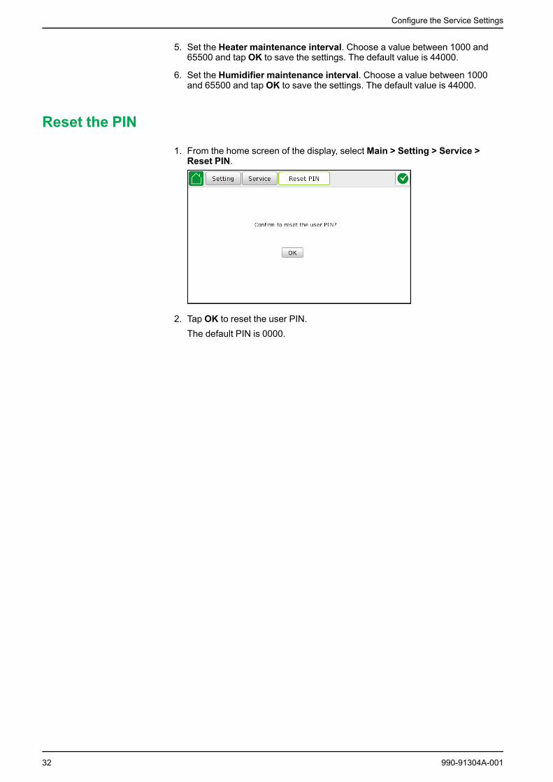
Reset the PIN
1. From the home screen of the display, select Main > Setting > Service >Reset PIN.
2. Tap OK to reset the user PIN.The default PIN is 0000.
32 990-91304A-001

View the Operation Status
View the Operation Status
View Basic Status InformationFrom the home screen of the display, select Main > Operation > Basic status.
View Detailed Status InformationFrom the home screen of the display, select Main > Operation > Detailed status.
On the detailed status screens you can check temperature and humidity, waterinlet/outlet temperature and pressure, actual value of supply fan speed, watervalve timely opening, and other components’ on/off status.
990-91304A-001 33

View the Operation Status
View Group Status InformationFrom the home screen of the display, select Main > Operation > Group status.
The role of the current cooling unit is shown on the screen.
The group status of the group, that the cooling unit is included in, is displayed onthe screen. There are four different group statuses:Master, Online, Backup, andSingle.
NOTE: In group control mode:• When local communication address is zero, the cooling unit always
displays Master.• When local communication address is not zero and the cooling unit is
in operation, it displays Online. If the cooling unit is not in operation, itdisplays Backup.
View Active AlarmsFrom the home screen of the display, select Main > Operation > Active Alarms.
34 990-91304A-001

View the Operation Status
Tap Clear alarm button to clear all the records.
Tap or symbol at the top-right corner on any screen to go to the ActiveAlarms page. Most of the alarms are automatically reset once the alarm iscleared.
NOTE: Some alarms such as inoperable fan needs to be cleared manually.Tap Clear alarm to manually clear the alarm.
View Information on Run HoursFrom the home screen of the display, select Main > Operation > Unit run hours.
On the Unit run hours screen you can get see how many hours the parts in thesystem have been running.
For information on how to reset these parameters, see Reset the Run Hours, page21.
View Temperature and Humidity CurveFrom the home screen of the display, select Main > Operation > Temperature-humidity curve.
NOTE:• The left ordinate is temperature value (℃), the right ordinate is humidity
value (%), the abscissa is time ( 5 minutes as a grid).• The yellow curve is temperature and the blue curve is humidity.
990-91304A-001 35

Troubleshooting
Troubleshooting
View the LogFrom the home screen of the display, select Main > Logs.
In the Logs page, the history of alarm information is available.
View the Data LogFrom the home screen of the display, select Main > Operation > Data log.
The display shows history data such as information on temperature and humidity,water inlet/outlet temperature and pressure, and valve opening.
To export the data log, insert a USB device in the bottom of the display and tapData export.
36 990-91304A-001
Troubleshooting
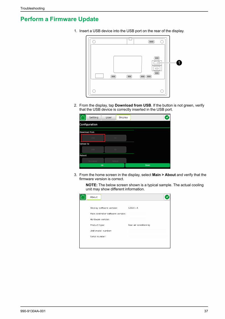
Perform a Firmware Update
1. Insert a USB device into the USB port on the rear of the display.
2. From the display, tap Download from USB. If the button is not green, verifythat the USB device is correctly inserted in the USB port.
3. From the home screen in the display, select Main > About and verify that thefirmware version is correct.
NOTE: The below screen shown is a typical sample. The actual coolingunit may show different information.
990-91304A-001 37
Troubleshooting
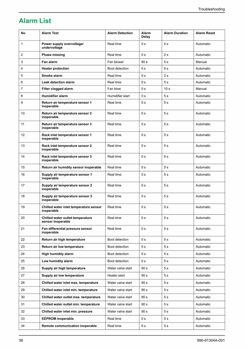
Alarm ListNo Alarm Text Alarm Detection Alarm
DelayAlarm Duration Alarm Reset
1 Power supply overvoltage/undervoltage
Real time 0 s 5 s Automatic
2 Phase missing Real time 0 s 2 s Automatic
3 Fan alarm Fan blower 60 s 5 s Manual
4 Heater protection Boot detection 0 s 5 s Automatic
5 Smoke alarm Real time 0 s 2 s Automatic
6 Leak detection alarm Real time 0 s 5 s Automatic
7 Filter clogged alarm Fan blow 0 s 10 s Manual
8 Humidifier alarm Humidifier start 0 s 5 s Automatic
9 Return air temperature sensor 1inoperable
Real time 0 s 5 s Automatic
10 Return air temperature sensor 2inoperable
Real time 0 s 5 s Automatic
11 Return air temperature sensor 3inoperable
Real time 0 s 5 s Automatic
12 Rack inlet temperature sensor 1inoperable
Real time 0 s 5 s Automatic
13 Rack inlet temperature sensor 2inoperable
Real time 0 s 5 s Automatic
14 Rack inlet temperature sensor 3inoperable
Real time 0 s 5 s Automatic
15 Return air humidity sensor inoperable Real time 0 s 5 s Automatic
16 Supply air temperature sensor 1inoperable
Real time 0 s 5 s Automatic
17 Supply air temperature sensor 2inoperable
Real time 0 s 5 s Automatic
18 Supply air temperature sensor 3inoperable
Real time 0 s 5 s Automatic
19 Chilled water inlet temperature sensorinoperable
Real time 0 s 5 s Automatic
20 Chilled water outlet temperaturesensor inoperable
Real time 0 s 5 s Automatic
21 Fan differential pressure sensorinoperable
Real time 0 s 5 s Automatic
22 Return air high temperature Boot detection 0 s 5 s Automatic
23 Return air low temperature Boot detection 0 s 5 s Automatic
24 High humidity alarm Boot detection 0 s 5 s Automatic
25 Low humidity alarm Boot detection 0 s 5 s Automatic
26 Supply air high temperature Water valve start 90 s 5 s Automatic
27 Supply air low temperature Heater start 90 s 5 s Automatic
28 Chilled water inlet max. temperature Water valve start 90 s 5 s Automatic
29 Chilled water inlet min. temperature Water valve start 90 s 5 s Automatic
30 Chilled water outlet max. temperature Water valve start 90 s 5 s Automatic
31 Chilled water outlet min. temperature Water valve start 90 s 5 s Automatic
32 Chilled water inlet min. pressure Water valve start 90 s 5 s Automatic
33 EEPROM inoperable Real time 0 s 0 s Automatic
34 Remote communication inoperable Real time 0 s 0 s Automatic
38 990-91304A-001

Troubleshooting
No Alarm Text Alarm Detection AlarmDelay
Alarm Duration Alarm Reset
35 Touch screen communicationinoperable
Real time 0 s 0 s Automatic
36 Local network communicationinoperable
Group control 0 s 0 s Automatic
37 Extension board communicationinoperable
Real time 0 s 3 s Automatic
38 Line A power supply inoperable Real time 0 s 0 s Automatic
39 Line B power supply inoperable Real time 0 s 0 s Automatic
40 Unit operating timeout Real time 0 s 0 s Manual
41 Fan operating timeout Real time 0 s 0 s Manual
42 Filter operating timeout Real time 0 s 0 s Manual
43 Heater timeout Real time 0 s 0 s Manual
44 Humidifier timeout Real time 0 s 0 s Manual
45 Rack inlet high temperature Water valve start 90 s 5 s Automatic
46 Rack inlet low temperature Heater start 90 s 5 s Automatic
47 High water level alarm Real time 0 s 5 s Automatic
48 Condensate management alarm Minimum runtime ofcondensation pump
0 s 5 s Automatic
Troubleshooting and Recommended Actions
Description Possible cause Components to check Recommended actions
Supply fan is inoperable. No input power to the system. Verify the power supply at theinput breaker.
Turn on the breaker/powersupply.
No input power to the supplyfan.
• Verify the power supplyfor the supply fan.
• Verify the working of thesupply fan.
• Correct the wiring.• Replace the fan relay or
the contactor, if inoperable.
Controller fails to signal therunning condition of the supplyfan.
• View the current supplyfan command in thedisplay.
• Check the supply fansignal wiring.
• Check the power on/offswitch of the supply fan.
• Replace the inoperablecomponents.
• Correct or tighten thewiring according to thewiring diagram.
Incorrect feedback wiring. Verify the feedback wiring. • Fasten the wires.• Correct the wiring.
Inoperable fan. Supply fan. Replace the inoperable supplyfan.
Water flow valve is inoperable. No input power to the watervalve.
Verify the power supply for thewater flow valve.
Correct the wiring.
Incorrect signal value Y set forthe water flow valve.
View the current signal value inthe display.
Correct to default value: Y1.
No humidification. No water charged. • Water supply• Solenoid valve• Water filter• Water pump
• Correct the operation of thecomponents.
• Clean the water filter.• Replace the inoperable
components.
Incorrect value set for thehumidifier to turn on.
In the display, view the currentsettings for humidification.
Correct the humidifier settings.
No heating. Incorrect value set for the heaterto turn on.
In the display, view the currentsettings for the heater to turnon.
Correct the heater settings.
990-91304A-001 39

Troubleshooting
Description Possible cause Components to check Recommended actions
Heater circuit failure. • Heater.• Heater contactor.• Heater protection device
(fused, located inside theheater).
Replace the inoperablecomponents.
Correct or tighten the wiringaccording to wiring diagram.
Temperature control is notaccurate.
Wrong location of remotetemperature sensor.
Sensors. Relocate the sensors in coldaisle.
Water leakage in the coolingunit.
The hose of condensation wateris not connected correctly.
Improper piping work.
Hose. Tighten the hose and configure itout of the cooling unit.
Piping system leakage. Pipe connections. Find the leakage and repair it.
The cooling unit is not leveledproperly.
Level the cooling unit byadjusting the leveling foot.
The thermal insulation isbroken.
Thermal insulation aroundpipes.
Replace the broken part or repairit.
Display does not work, but thecooling unit is in operation.
Display circuit inoperable. Display.
Connection cable.
• Tighten the wiringaccording to the wiringdiagram
• Replace the inoperablecomponents.
Air filter clogged. Air filter is too dirty. Air filter. Clean the air filter or replace itwith a new one.
Incorrect air pressure differentialswitch setting.
Arrow on the dial of the airpressure differential switchshould be at 350.
Correct the setting to 350.
Inoperable air pressuredifferential switch.
Air pressure differential switch. If the switch is open while thefilter is clean and the setting iscorrect, replace the switch.
Alarms do not display on themonitoring equipment.
The exterior monitoringequipment is not powered on.
Incorrect communication.
The wiring is correct and haveoutput.
• Correct the wiring.• Inform that the equipment
is functioning correctly andask them to check themonitoring equipment.
40 990-91304A-001


Schneider Electric35 rue Joseph Monier92500 Rueil MalmaisonFrance
+ 33 (0) 1 41 29 70 00
*990-91304A-001*As standards, specifications, and design change from time to time,please ask for confirmation of the information given in this publication.
© 2019 – 2019 Schneider Electric. All rights reserved.
990-91304A-001