EASTOVER SANITARY DISTRICT STANDARD SPECIFICATION & GENERAL PROVISIONS...
68
General Guidelines -1 EASTOVER SANITARY DISTRICT STANDARD SPECIFICATION & GENERAL PROVISIONS FOR THE EXTENSTION OF WATER & SEWER UTILITIES General Provisions 1. General The availability of water and or sewer from a public system is recognized as a factor which significantly influences land development. Therefore, it is the policy of the System to expand its production capacity and distribution network to support the implementation of Cumberland County and the Town of Eastover’s Land Development/Use Plan consistent with those adopted plans and policies. Eastover Sanitary District is a Unit of Local Government that operates under its independent governing body with policies and procedures that have been adopted with the intent of providing water and sewer service to existing residents and landowners. The availability of water and sewer from the System should not be accepted as justification for changing or granting exceptions to land uses prescribed in the development plan(s) in any instance where more intensive uses of the parcel are precluded by factors other than the availability of utilities. These Standard Specifications are intended to serve as a technical guide for the design and installation of water and sewer utilities to serve residents and landowners that are located within the geographical boundaries of Eastover Sanitary District and in such cases where residents and property can be served within the parameters of Local and State Guidelines and rules as they address utility service. Eastover Sanitary District Policies and Ordinances can be found at the following locations: www.Eastoversanitarydistrict.com Cross Connection Control Ordinance Ordinance Requiring Mandatory Water & Sewer Connection Under Certain Conditions Water System Rules & Regulations Fats, Oil & Grease (FOG) Control Ordinance Sanitary Sewer Specifications - www.faypwc.com/design_standards.aspx . ESD sewer extensions shall follow the Public Works Commission of Fayetteville Design Standards found at the afore mentioned web- site. 2. Expansion of the System’s Water Distribution and Sanitary Sewer Networks: Developer Extensions – Planning and Design Guidelines: 1. The Developer shall supply a request for utility service including a preliminary site plan include the location of the site relative to existing utilities, proposed water and or sewer flows and fire flow analysis request specifically for the site. 2. Assuming that the site can be served by existing utilities and adequate capacity is available and that the site has or will obtain all necessary approvals from Cumberland County or the appropriate planning jurisdiction the developer shall submit a formal application for service with the Eastover Sanitary District and agrees to pay all applicable fees and rates. 3. When service is requested for newly developed site the Developer must obtain all planning approvals for the land use with the appropriate jurisdiction. 4. Once planning approvals have been obtained the developer shall meet the following submittal requirements.
Transcript of EASTOVER SANITARY DISTRICT STANDARD SPECIFICATION & GENERAL PROVISIONS...

General Guidelines -1
EASTOVER SANITARY DISTRICT STANDARD SPECIFICATION & GENERAL PROVISIONS FOR THE EXTENSTION OF WATER & SEWER UTILITIES
General Provisions
1. General The availability of water and or sewer from a public system is recognized as a factor which significantly influences land development. Therefore, it is the policy of the System to expand its production capacity and distribution network to support the implementation of Cumberland County and the Town of Eastover’s Land Development/Use Plan consistent with those adopted plans and policies. Eastover Sanitary District is a Unit of Local Government that operates under its independent governing body with policies and procedures that have been adopted with the intent of providing water and sewer service to existing residents and landowners. The availability of water and sewer from the System should not be accepted as justification for changing or granting exceptions to land uses prescribed in the development plan(s) in any instance where more intensive uses of the parcel are precluded by factors other than the availability of utilities. These Standard Specifications are intended to serve as a technical guide for the design and installation of water and sewer utilities to serve residents and landowners that are located within the geographical boundaries of Eastover Sanitary District and in such cases where residents and property can be served within the parameters of Local and State Guidelines and rules as they address utility service. Eastover Sanitary District Policies and Ordinances can be found at the following locations: www.Eastoversanitarydistrict.com
Cross Connection Control Ordinance Ordinance Requiring Mandatory Water & Sewer Connection Under Certain Conditions Water System Rules & Regulations Fats, Oil & Grease (FOG) Control Ordinance Sanitary Sewer Specifications - www.faypwc.com/design_standards.aspx . ESD sewer extensions shall
follow the Public Works Commission of Fayetteville Design Standards found at the afore mentioned web-site.
2. Expansion of the System’s Water Distribution and Sanitary Sewer Networks: Developer Extensions – Planning and Design Guidelines:
1. The Developer shall supply a request for utility service including a preliminary site plan include the location of the site relative to existing utilities, proposed water and or sewer flows and fire flow analysis request specifically for the site.
2. Assuming that the site can be served by existing utilities and adequate capacity is available and that the site has or will obtain all necessary approvals from Cumberland County or the appropriate planning jurisdiction the developer shall submit a formal application for service with the Eastover Sanitary District and agrees to pay all applicable fees and rates.
3. When service is requested for newly developed site the Developer must obtain all planning approvals for the land use with the appropriate jurisdiction.
4. Once planning approvals have been obtained the developer shall meet the following submittal requirements.

General Guidelines -2
a. Site plan indicating and showing all on-site utilities along with a summary of required water and sewer flows for the entire site including current and future phases. ESD shall review and provide a statement of ability to serve.
b. Provided that the site can be serviced by ESD the developer or his agent shall provide detailed engineering plans for the site. A minimum of two sets of plans shall be provided for review. The plans shall be minimum 24” x 36” drawings and one CD with a PDF of the design plans.
c. ESD and their engineering representative shall have two weeks to review the subject plans and provide comments or approvals to the Developer. The Developer shall be responsible for paying and applicable review fees that ESD incurs from outside parties not to exceed $1,000 based upon and hourly rate of $100/hour.
d. Upon approval of development plans by ESD relating to utility construction the Developer and or their Engineer shall submit all applicable permit applications to ESD including two files copies for ESD. The Developer shall be responsible for all applicable cost associated with permitting and approvals.
e. Any and all required easements for utilities shall be a minimum of 20ft in width and shall be recorded in the name of Eastover Sanitary District.
f. Any required off-site utility design, fees and construction shall be the sole responsibility of the Developer. No off-site utility sizing and design shall be done without the input, review and approval of ESD. ESD shall review off-site utility construction with regard to future expansions within the boundaries of the District and any determination of size or capacity of the off-site utilities shall be at the sole discretion of ESD within reasonable planning parameters.
g. ESD may also require that off-site utilities depending on the magnitude, scope and complexity are designed by ESD’s Consulting Engineer with those fees being paid by the developer unless agreement is made to share those fees between ESD and the Developer.
5. Construction Phase: a. Once permits have been obtained a pre-construction conference shall be held relating to the
site utility construction shall be held at the ESD office. b. The Developer shall provide ESD with all copies of regulatory and planning approvals prior to
the commencement of construction. c. The Developer shall provide ESD with two copies approved construction plans (24”x36”),
construction shop drawings and construction schedules. d. The Developer shall provide ESD with all contractor points of contacts during the course of
construction. e. Upon the completion of construction phases ESD shall witness all testing of the utility and any
required regulatory certifications prior to placing the utility into service. f. The post construction phase shall include the submission of As-Built or Record Drawings to
ESD indicating the location of all components of the utility(s) installed. As-Builts shall include two 22x36 paper copies and a PDF of the signed drawings submitted electronically on a CD or “flash drive”. As-Builts shall include physical references as follows:
i. Water Mains – locations to edge of pavement and pavement centerlines at 50-ft intervals.
ii. Valves and Hydrants – locations to permanent features (minimum three reference points) such as storm drainage features, power poles, pavement centerlines, fire hydrants and any other appropriate permanent above-ground feature.
iii. Fittings – Locations to permanent features (minimum two reference points). iv. Provide field located GPS points (sub-meter accuracy) to all valves, hydrants, fittings in an
electronic format. v. Water Service Locations - Provide field located GPS points (sub-meter accuracy) to all
meter boxes. vi. Sewer Force Mains shall follow the same procedure as water mains shown above.
General Guidelines -3
vii. Gravity Sewer – Mapping shall be provide by a Licensed Land Surveyor showing the manhole rim locations vertical and horizontal, invert elevations, size and material of the sewer main as well as the calculated as-built slope of the sewer mains.
viii. Sewer Pump Stations - as-built survey of the built conditions as well as two copies of complete Operation and Maintenance Manuals and certified pump station start-up reports verifying that the operating conditions meet the designed and permitted conditions of the pump stations.
3. Ownership: Upon the completion of the construction phase and acceptance of the work the developer/owner shall transfer ownership to Eastover Sanitary District with the written statement of a One-year warranty on products and installation. ESD shall become the owner/operator of the utility. All real property associated with the utility installation (eg. pump station sites, master meter locations and utility easements) shall be deeded or established in the name of Eastover Sanitary District. ESD shall not assume responsibility of streets, storm drainage or stormwater management facilities but only those components associated with the potable water and sanitary sewer systems. 4. Non-Conforming Utilities: ESD shall not assume ownership of any non-conforming component of the utility installation, eg. those not meeting the intent of the approved plan or not in accordance with the specifications and also those that do not meet the applicable State/Local or Federal Standards. 5. Fees: The Developer/Customer shall pay all applicable development fees and monthly fees incurred as necessary to become a customer of the Eastover Sanitary District. 6. Eastover Sanitary District Contact Information Eastover Sanitary District Ms. Connie Spell, General Manager [email protected] 3876 Dunn Road Eastover, NC 28312 (910) 229-3716 – Phone Mr. Dave Strum, ORC Envirolink, Inc. – Contracted Operations [email protected] (252) 235-8763 Web-Site: www.eastoversanitarydistrict.com
DS SECTION 1 - Water Distribution Page 1 -1
DETAILED SPECIFICATIONS
SECTION 1 - WATER DISTRIBUTION
PART 1 GENERAL REFERENCES The publications listed below form a part of this specification to the extent referenced. The publications are referred to in the text by the basic designation only. Latest Revisions shall be applicable to all references.
AMERICAN NATIONAL STANDARDS INSTITUTE (ANSI)
ANSI B18.5.2.1M (1981; R 1995) Metric Round Head Short Square Neck Bolts
AMERICAN SOCIETY OF MECHANICAL ENGINEERS (ASME)
ASME/ANSI B16.1 (1989) Cast Iron Pipe Flanges and Flanged Fittings
AMERICAN SOCIETY FOR TESTING AND MATERIALS (ASTM)
ASTM A 48 (1994) Standard Specification for Grey Iron Castings
ASTM A 47 (1990) Ferritic Malleable Iron Castings ASTM A 126 (1995) Standard Specification for Grey Iron Castings for
Valves, Flanges and Pipe Fittings ASTM A 276 (2003) Standard Specification for Stainless Steel Bars and
Shapes
ASTM A 307 (1994) Carbon Steel Bolts and Studs, 60,000 psi Tensile Strength
ASTM A 536 (1984; R 1993) Ductile Iron Castings
ASTM A 563 (1994) Carbon and Alloy Steel Nuts
ASTM C 94 (1994) Ready-Mixed Concrete ASTM D 429 (1999) Standard Specification for Rubber-Property
Adhesion to Rigid Substrates
DS SECTION 1 - Water Distribution Page 1 -2
AMERICAN WATER WORKS ASSOCIATION (AWWA)
AWWA B300 (2010) Hypochlorites AWWA B301 (2010) Liquid Chlorine AWWA C104/A21.4 (2008) Cement-Mortar Lining for Ductile-Iron Pipe and
Fittings for Water
AWWA C110/A21.10-12 (2012) Ductile-Iron and Gray-Iron Fittings, 3 in. Through 48 in. (75 mm Through 1200 mm), for Water and Other Liquids
AWWA C111/A21.11.12 (2007) Rubber-Gasket Joints for Ductile-Iron Pressure
Pipe and Fittings
AWWA C115/A21.15 (2011) Flanged Ductile-Iron Pipe with Ductile-Iron or Gray-Iron Threaded Flanges
ANSI/AWWA C151/A21.51 (2009) Ductile-Iron Pipe, Centrifugally Cast, for Water or
Other Liquids AWWA C207 (2007) Steel Pipe Flanges for Waterworks Service
AWWA C502 (2005) Dry-Barrel Fire Hydrants AWWA C504 (2010) Rubber Sealed Butterfly Valves
AWWA C508 (2009) Swing-Check Valves for Waterworks Service, 2 in.
(50 mm) Through 24 in. (600 mm) NPS
AWWA C509 (2009) Resilient-Seated Gate Valves for Water and Sewerage Systems
AWWA C512 (2001) Air Release, Air/Vacuum, and Combination Air
Valves for Waterworks Service AWWA C515 (2001) Reduced Wall, Resilient Seated Gate Valves for
Waterworks Service AWWA C550 (2001) Protective Epoxy Coatings for Valves and
Hydrants
AWWA C600 (2010) Installation of Ductile-Iron Water Mains and Their Appurtenances

DS SECTION 1 - Water Distribution Page 1 -3
AWWA C605 (2006) Underground Installation of PVC Pressure Pipe and Fittings for Water
AWWA C651 (1992) Disinfecting Water Mains
AWWA C900 (2007)PVC Pipe and Fabricated Fittings, 4 In. Through 12 In. (100 mm Through 300 mm), for Water Transmission and Distribution
AWWA C901 (2008)Polyethylene (PE) Pressure Pipe and Tubing, 3/4
In. CTS (13 mm) Through 3 In. (76 mm), for Water Service
AWWA C905 (2010)Polyvinyl Chloride (PVC) Pressure Pipe and
Fabricated Fittings, 14 In. Through 48 In. (350 mm Through 1,200 mm)
AWWA C906 (2007) Polyethylene (PE) Pressure Pipe and Fittings, 4 In.
(100 mm) Through 63 In. (1600 mm), for Water Distribution and Transmission.
AWWA C909 (2009) Molecularly Oriented Polyvinyl Chloride (PVCO)
Pressure Pipe, 4 In. Through 24 In. (100 mm Through 600 mm), for Water, Wastewater, and Reclaimed Water Service
NATIONAL SANITATION FOUNDATION
NSF 61 (2003) Drinking Water System, Health Effects
NCAC, TITLE 15A, DENR SUBCHAPTER 18C, WATER SUPPLIES
Par. .0906 Relation of Water Mains to Sewers Par. .1003 Disinfection of Storage Tanks and Distribution Systems
UNDERWRITERS LABORATORIES INC. (UL)
UL 312 (2004) Standards for Check Valves for Fire Protection Service
UL 789 (1993; R 1994) Indicator Posts for Fire-Protection Service
DESIGN REQUIREMENTS
General A full hydraulic analysis utilizing computer modeling techniques will be required for all improvements to the ESD water system. Proposed improvement operating pressures shall meet all North Carolina regulatory requirements including a minimum fire hydrant flow of 500 gpm at a
DS SECTION 1 - Water Distribution Page 1 -4
residual pressure of 20 psi system wide. The following general guidelines for design and materials shall be adhered to.
1. Water Main pipe material shall be Ductile Iron or PVC. Requirements for ductile iron pipe class can be found in the paragraphs below. All PVC pipe 4” through 12” shall be a minimum classification of AWWA C900 DR 18 (Class 150). 2” PVC pipe shall be SDR 21.
2. Fire hydrants shall be located no more than 1,000 feet apart and at a maximum of 500 feet from any lot or unit within a subdivision.
3. Valves shall be installed on all distribution mains and hydrants according to the following schedule: 3 valves at crosses; 2 valves at tees; and 1 valve on each hydrant branch. A main line valve shall be installed at every 100 feet per 1-inch diameter main up to a distance of 2000 feet between valves. ESD at their discretion may require the installation of additional valves.
4. Locate fire hydrants along R/W line and at lot corners where possible. 5. Minimum depth of bury for water mains shall be 3.5’. 6. All water main crossing under storm drain shall be ductile iron. 7. Water main shall not be installed under pavement section, curb and gutter, or sidewalk
except when crossing perpendicular to those surfaces. All water mains installed under paved or roadway surfaces shall be installed as Ductile Iron Pipe.
8. ESD may require stub outs for future expansion, including valves, piping, and fittings. Water Distribution Mains The Contractor shall furnish all types of pipe and other incidentals required for the construction of a complete water system as shown on the drawings and as specified herein. Unless otherwise noted, the materials listed below are acceptable to ESD for use in water distribution systems. Should the Contractor desire to use other materials not listed in these specifications, written permission must be obtained from ESD. All material shall be free from defects impairing strength and durability and be of the best commercial quality for the purposes specified. It shall have structural properties sufficient to safely sustain or withstand strains and stresses to which it is normally subjected and be true to detail. Connect to existing water mains as indicated. Provide water main accessories, gate valves, fire hydrants, combination air valves, service laterals, water meters, and backflow preventers as specified and where indicated. All materials being stored shall be stored and protected from the elements to the satisfaction of ESD. Water Service Lines The Contractor shall furnish all materials and all other incidentals required for the installation of a complete water service connection as shown on the detail drawings and as specified herein. Unless otherwise noted, the materials listed below are acceptable to ESD for use in water services. Should the Contractor desire to use other materials not listed in these specifications, written permission must be obtained from ESD. All material shall be free from defects impairing strength and durability and be of the best commercial quality for the purposes specified. It shall have structural properties sufficient to safely sustain or withstand strains or stresses to which it is normally subjected and be true to detail. Materials supplied shall be of the designations and description indicated on the plans or described herein. Provide water service lines indicated as 1” lines from the new water distribution main through the meter box to be located at the boundary of the existing street right-of-way. Water service lines shall be 1” PE pipe-CTS pipe rated at 200 psi and shall include a 12GA tracer wire extended into the meter box. Provide water service line appurtenances as specified. Irrigation connections shall be metered separately. Meter boxes shall be installed shall be installed at the property lines of the service addresses.

DS SECTION 1 - Water Distribution Page 1 -5
PRODUCT SUBMITTALS Submit two (2) copies of the following to ESD for review and approval before beginning construction. Product Data Submit manufacturer’s standard drawings or catalog cuts, except submit both drawings and cuts for push-on joints. Include information concerning gaskets with submittal for joints and couplings.
A. Water distribution main piping, fittings, joints, valves, valve boxes and couplings. B. Water service line piping and appurtenances (saddles, corporation stops, compression
fittings, meter setters, meter boxes, etc.). C. Fire Hydrants D. Combination Air Valves and Precast Concrete Manholes.
E. Backflow Devices
Instructions
A. Installation procedures for water piping. Certificates Certificates shall attest that tests set forth in each applicable referenced publication have been performed, whether specified in that publication to be mandatory or otherwise and that production control tests have been performed at the intervals or frequency specified in the publication. Other tests shall have been performed within 3 years of the date of submittal of certificates on the same type, class, grade, and size of material as is being provided for the project.
A. Water distribution main piping, fittings, joints, valves, and couplings. B. Water service line piping, fittings, joints, valves, and couplings.
C. Shop-applied lining and coating D. Fire Hydrants F. Backflow Devices
DELIVERY, STORAGE, AND HANDLING Delivery and Storage Inspect materials delivered to site for damage. Unload and store with minimum handling. Store materials on site in enclosures or under protective covering. Store plastic piping, jointing materials

DS SECTION 1 - Water Distribution Page 1 -6
and rubber gaskets under cover out of direct sunlight. Do not store materials directly on the ground. Keep inside of pipes, fittings, valves and hydrants free of dirt and debris. Handling Handle pipe, fittings, valves, hydrants, and other accessories in a manner to ensure delivery to the trench in sound undamaged condition. Take special care to avoid injury to coatings and linings on pipe and fittings; make satisfactory repairs if coatings or linings are damaged. Carry, do not drag pipe to the trench. Store plastic piping, jointing materials and rubber gaskets that are not to be installed immediately, under cover out of direct sunlight. PART 2 PRODUCTS
WATER DISTRIBUTION MAIN MATERIALS
Polyvinyl Chloride Pipe (PVC) Dimension Ratio 18 PVC pipe shall conform to ANSI/AWWA C900 latest revision for polyvinyl chloride pressure pipe sizes 4 inch through 12 inch. Class 150, DR 18 pipe or as called for on the plans or in the schedule bid items shall be furnished. The pipe shall be plainly marked with the following information: manufacturer’s name, size, material (PVC) type and grade or compound, NSF seal, pressure class and reference to appropriate product standards. Pipe shall be furnished in 20 ft. laying lengths. Random lengths shall be a minimum of 10 feet long and shall comprise no more than 15 percent of the length of the piping system. Pipe shall be furnished in factory-packaged units. Pipe shall be furnished in cast iron pipe equivalent outside diameters with rubber-gasketed separate couplings or push-on joints. Pipe shall not fail when subjected to the following tests; (1) sustained pressure (2) burst pressure (3) flattening and extrusion quality. Tests shall be conducted as outlined in ANSI/AWWA C900-07. Each length of PVC pipe shall pass a hydrostatic integrity test at the factory of 4 times the pressure class of the pipe for 5 seconds. PVC Resin shall meet the requirements of ASTM D1784. Standard Dimension Ratio 21: PVC pipe shall be SDR 21 as called for on the plans or in the schedule bid items shall be furnished. The pipe shall be plainly marked with the following information: manufacturer's name, size, material (PVC) type and grade or compound, NSF Seal, pressure rating and reference to appropriate product standards.
1. Standards: PVC Pipe shall conform to the following:
a. Material: Virgin PVC resin, ASTM D1784 b. Standard Dimension Ratio : SDR 21 c. Pressure Rating: 200 psi @ 2.0 factor of safety d. Sustained Pressure Requirement: 420 psi for 1,000 hrs., ASTM D1598, ASTM D2241 e. Quick Burst Pressure: 630 psi for 60 sec., ASTM D1599
Pipe that conforms to ASTM-F1483 for Molecular Oriented Pipe (MOP), with a Hydrostatic design basis (HDB) of 7100 psi and pressure rating of 200 psi with an IPS OD is an acceptable alternative to SDR21 pipe.
DS SECTION 1 - Water Distribution Page 1 -7
Joints for pipe shall be push-on joints. Joints at fittings shall be mechanical joints unless otherwise indicated.
High Density Polyethylene Pipe (HDPE):
A. General: Materials used for the manufacturing of polyethylene pipe and fittings shall be PE 3408 High Density Polyethylene (HDPE) meeting the ASTM D3350 cell classification of 345434C. All HDPE pipe shall have a minimum pressure rating of 200psi and shall be Dimension Ratio (DR) 9.
The material used in the production of potable water pipe shall be approved by the National Sanitation Foundation (NSF).
B. Pipe Thickness: The material shall have a minimum Hydrostatic Design Basis
(HDB) of 1600 psi at 73F when tested in accordance with PPI TR-3 and shall be listed in the name of the pipe and fitting manufacturer in PPI TR-4.
Polyethylene pipe shall be manufactured in accordance with AWWA C906 for sizes 4” through 54”.
Permanent identification of piping service shall be provided by co-extruding longitudinal blue stripes into the pipes outside surface. The striping material shall be the same material as the pipe material except for color.
C. Joints: Butt fusion or Electrofusion welded in accordance with ASTM D3261.
D. Marking: The net weight, pressure class or nominal thickness, sampling period and
manufacturer shall be marked on each pipe. The Dimension Ratio of DR9 shall be plainly marked on the pipe.
Ductile Iron Pipe
Ductile-Iron Pipe, except flanged pipe, ANSI/AWWA C151/A21.51, NSF 61 certified, Pressure Class 350 for pipe up to 12” diameter. All larger pipe shall be minimum Pressure Class 250 unless otherwise required due to design considerations. Flanged pipe, AWWA C115/A21.15. Ends of pipe and fittings shall be suitable for the specified joints. Pipe and fittings shall have cement-mortar lining, AWWA C104/A21.4, standard thickness. Ductile iron shall conform to ASTM A-536, latest revision, Grade 70-50-05. Ductile Iron Pipe Joints Joints for pipe shall be push-on joints unless otherwise indicated. Joints for fittings shall be mechanical joints unless otherwise indicated. All transitions from PVC to DIP shall require a Mechanical Joint Sleeve.

DS SECTION 1 - Water Distribution Page 1 -8
A. Push-On Joints: Shape of pipe ends and fitting ends, gaskets, and lubricant for joint assembly, AWWA C111/A21.11.
1. Restrained Push-On Joints: Restrained push-on joints for pipe where indicated shall be
designed for a working pressure of 350 psi for 4”-24” pipe. Restrained push-on joints shall be capable of being deflected a minimum of 4 degrees after assembly for pipe through 12” and 3 degrees for pipe 14” – 24”. Restrained push-on joints shall be manufactured, not by specialized gripping segment gasket installation.
B. Mechanical Joints: Dimensional and material requirements for pipe ends, glands, bolts and nuts, and gaskets, AWWA C111/A21.11.
1. Restrained Flexible Bolted Joints: Restrained mechanical joint pipe (and connections to
MJ fittings and valves) shall utilize a flexible bolted joint designed for a working pressure of 350 psi for 4” –24” pipe. Restrained flexible bolted joints shall be capable of being deflected a minimum of 4 degrees for pipe through 12”, 3 degrees for 14” and 16” pipe, 2.5 degrees for 18” and 20” pipe and 2 degrees for pipe 24” through 36”.
C. Flanged Joints: Bolts, nuts, and gaskets for flanged connections as recommended in the
Appendix to AWWA C115/A21.15. Flange for setscrewed flanges shall be of ductile iron, ASTM A 536, Grade 65-45-12, and conform to the applicable requirements of ASME/ANSI B16.1, Class 250. Setscrews for setscrewed flanges shall be 190,000-psi tensile strength, heat treated and zinc-coated steel. Gasket for setscrewed flanges shall conform to applicable requirements for mechanical-joint gaskets specified in AWWA C111/A21.11. Design of setscrewed gasket shall provide for confinement and compression of gasket when joint to adjoining flange is made. Flanged joints shall only be permitted in above ground of vault installations. Flanged joints shall not be used in direct bury applications.
D. Sleeve-Type Mechanical Couplings
Couplings shall be designed to couple plain-end piping by compression of a ring gasket at each end of the adjoining pipe sections. The coupling shall consist of one middle ring flared or beveled at each end to provide a gasket seat; two follower rings; two resilient tapered rubber gaskets; and bolts and nuts to draw the follower rings toward each other to compress the gaskets. The middle ring and the follower rings shall be true circular sections free from irregularities, flat spots, and surface defects; the design shall provide for confinement and compression of the gaskets. For ductile iron and PVC plastic pipe, the middle ring shall be of cast-iron or steel; and the follower rings shall be of malleable or ductile iron. Cast iron, ASTM Malleable and ductile iron shall, conform to ASTM A 47 and ASTM A 536, respectively. Steel shall have a strength not less than that of the pipe. Gaskets shall be designed for resistance to set after installation and shall meet the applicable requirements specified for gaskets for mechanical joint in AWWA C111/A21.11. Bolts shall be track-head type, ASTM A 307, Grade A, with nuts, ASTM A 563, Grade A; or round-head square-neck type bolts, ANSI B18.5.2.1M and ANSI/ASME B18.5.2.2M with hex nuts, ASME/ANSI B18.2.2. Bolts shall be 5/8 inch in diameter; minimum number of bolts for each coupling shall be 8 for 12-inch pipe, 8 for 8-inch pipe, and 6 for 6-inch pipe. Boltholes in follower rings shall be of a shape to hold fast the necks of the bolts used. Mechanically coupled
DS SECTION 1 - Water Distribution Page 1 -9
joints using a sleeve-type mechanical coupling shall not be used as an optional method of jointing except where pipeline is adequately anchored to resist tension pull across the joint.
Ductile Iron Pipe Fittings Ductile iron fittings shall conform to ANSI A 21.10 (AWWA C-110), latest revision with the exception of the manufacturer’s design dimensions and thickness and be NSF 61 certified. Fittings shall have a working pressure rating of 350 psi for fittings, 12 inch and under and 250 psi for fittings over 12 inch. Ductile iron shall conform to ASTM A-536, latest revision, Grade 70-50-05.
A. Thickness Design: Nominal thickness of the fittings shall be equal to Class 51 ductile iron
pipe as specified in ANSI A 21.51 (AWWA C-151).
B. Lining: Fittings shall have a cement mortar lining and seal coating conforming with ASNI A 21.4 (AWWA C-104), latest revision.
C. Exterior Coating: Fittings shall have an outside coating of bituminous material in
accordance with the manufacturer’s specifications. The final coat shall be continuous and smooth being neither brittle when subjected to low temperatures nor sticky when exposed to hot sun. The coating shall be strongly adherent to the pipe at all temperatures.
D. Fitting Joints: Fittings shall have mechanical or flanged joints as indicated and specified
herein.
1. Mechanical Joint: ANSI Specification A 21.11 (AWWA C-111), latest revision, for three inch pipe and larger. Bolted mechanical joint fittings shall be used with ductile iron pipe, PVC pipe, for all hydrant tees, and where specifically called for on the plans or in the Schedule of Bid Items.
a. Restrained Flexible Bolted Joint: Restrained MJ fittings shall be designed for a
working pressure of 350 psi for 4”-24” ductile iron pipe. Fittings such as these shall be part of a manufactured flexible bolted pipe restraint system as described above for MJ ductile iron pipe.
b. Mega Lug Restraint for D.I.P.: Mega Lugs may be used for restraint of mechanical
joint fittings. The restraint mechanism shall consist of a plurality of individually actuated gripping surfaces to maximize restraint capability. Glands shall be manufactured of ductile iron conforming to ASTM A536-80. The gland shall be such that it can replace the standardized mechanical joint gland and can be used with the standardized mechanical joint bell. Twist off nuts, sized the same as tee-head bolts shall be used to insure proper actuating of restraining devices. The restraining glands shall have a pressure rating equal to that of the pipe on which it is used. When mechanical thrust restraints are used concrete thrust blocking shall be deleted from the installation.
DS SECTION 1 - Water Distribution Page 1 -10
2. Flanged Joint: Flanged fittings shall be constructed of ductile iron with flanges drilled and faced per ANSI B 16.1 for both 125 Lb. working pressure.
Valves, Hydrants, and Other Water Main Accessories Resilient-Seated Gate Valves for Buried Piping Resilient-Seated Gate Valves for buried piping shall conform to AWWA C509 or AWWA C515 unless otherwise specified and shall be NSF 61 certified. 24” valves shall have bevel gearing for horizontal installation. Valves smaller than 24” shall be configured for vertical installation. Valves shall be nonrising stem type with mechanical-joint ends and shall open by counterclockwise rotation of the valve stem. Stuffing boxes shall have 0-ring stem seals, except for those valves for which gearing is specified, in which case use conventional packing in place of o-ring seal. Stuffing boxes shall be bolted and constructed so as to permit easy removal of parts for repair. The wedge shall be cast iron, completely encapsulated with resilient material. The resilient sealing material shall be permanently bonded to the cast iron wedge with a rubber-tearing bond to meet ASTM D429. The gate valve stem and stem nut shall be copper alloy. The body and bonnet shall be coated both interior and exterior with a fusion bonded heat cured thermo setting material meeting all application and performance requirements of AWWA C550. The minimum design working pressure shall be for valves up to 12” and 200 psi for valves larger than 12”. Resilient seated gate valves shall be manufactured by American Flow Control or Mueller. Valves shall be of one manufacturer per project. Resilient-Seated Gate Valves in Valve Pit(s) and Aboveground Locations Resilient-Seated Gate Valves for installation in vaults or above ground shall conform to AWWA C509 or AWWA C515 unless otherwise specified and shall be NSF 61 certified. Valves shall be nonrising stem type with flanged ends. Valves shall be of one manufacturer. Check Valves Swing-check type, AWWA C508 or UL 312. Valves conforming to: (1) AWWA C508 shall have iron or steel body and cover and flanged ends, and (2) UL 312 shall have cast iron or steel body and cover, flanged ends, and designed for a working pressure of 200 psi. Materials for UL 312 valves shall conform to the reference standards specified in AWWA C508. Valves shall have clear port opening. Valves shall be weight-loaded where indicated. Valves shall be of one manufacturer. Butterfly Valves for Buried Piping (Larger than 12”) Butterfly valves shall be manufactured in accordance with the latest revision of AWWA C504 for Class 150B service and shall be NSF 61 certified. Valve bodies shall be constructed of cast iron ASTM A-126 Class B and conform to AWWA C504 for laying lengths and minimum body shell thickness. End connections shall be mechanical joint. Valve discs shall also be made from cast iron ASTM A-126 Class B or ASTM A-48 Class 40 in sizes 24" and smaller. Disc shall be furnished with 316 stainless steel seating edge to mate with the rubber seat on the body. Valve seat shall be Buna-N rubber located on the valve body. Valves 20" and smaller shall have bonded seats that meet test procedures outlined in ASTM D-429 Method B. Sizes 24" and larger shall be retained in the valve body by mechanical means without use of metal retainers or other devices located in the flow stream. Valve shafts shall be 18-8 type 304 stainless steel conforming to ASTM A-276. Shaft seals shall be standard self-adjusting split V packing. Shaft seals shall be of a design allowing replacement

DS SECTION 1 - Water Distribution Page 1 -11
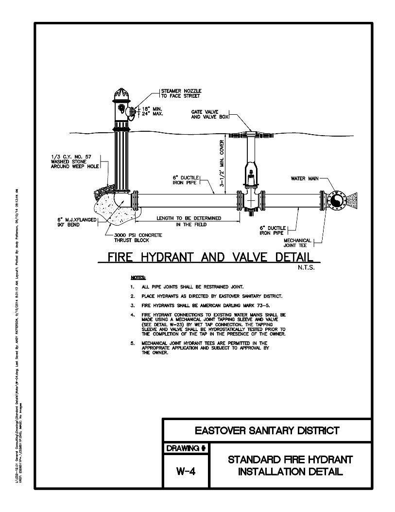
without removing the valve shaft. Valve bearings shall be sleeve type that are corrosion resistant and self-lubricating. Valve actuators shall be fully grease packed and have stops in the open/close position. The actuator shall have a mechanical stop which will withstand an input torque of 450 ft. lbs. against the stop. The traveling nut shall engage alignment grooves in the housing. The actuators shall have a built in packing leak bypass to eliminate possible packing leakage into the actuator housing. All internal and/or external surfaces shall be covered with a polyamide cured epoxy coating applied over a sand blasted "new white metal surface" per SSPC-SP10 to a minimum of 6 mils in compliance with AWWA C550. Butterfly valves shall be manufactured by Mueller, Pratt, or an approved equal. Fire Hydrants Dry-Barrel Fire hydrants shall be manufactured to meet or exceed ANSI/AWWA C502-94. Fire hydrants shall be of the compression type with 4-1/2” valve opening designed to close against line pressure. Fire hydrants shall be furnished with a sealed oil or grease reservoir located in the bonnet, so that all threaded and bearing surfaces are automatically lubricated. Teflon washers shall be used for ease of operation. The seat ring shall be bronze and threaded into a drain ring located between the lower barrel and shoe. The hose and pumper nozzles shall be threaded. The threads for nozzles shall be National Standard. The hydrants shall have two (2) 2-1/2” hose nozzles with cap, and one (1) 4-1/2” pumper nozzle and cap. Hydrants shall have a minimum 36” bury and shall stand approximately 30” above ground elevation. Hydrants shall be designed with a breakaway feature that will break cleanly upon impact. This shall consist of a two-part breakable safety flange. The operating nut shall be 1-1/2” pentagonal and shall open counterclockwise. All hydrants shall be cast marked on the outside such that visible identification can me made as to type and design. All hydrants shall receive two (2) exterior shop coats of OSHA safety color “Red” with all caps in a high gloss enamel as specified by ANSI/AWWA C502-94. In addition, one finish exterior coat, as described, shall be applied after construction operations are complete, as deemed necessary by ESD. The paint used shall be as manufactured by Tnemec or equal. Fire Hydrants shall be American Darling Mark 73-5. All hydrants shall receive two (2) exterior shop coats of fire hydrant paint as specified by AWWA C-502. In addition, one finish exterior coat of fire engine red paint shall be applied after construction operations are complete. The paint shall comply with the following schedule: MANUFACTURER SHOP PRIMER FINISH COAT Tnemec 37-77 Tneme-Coat Tapping Sleeves and Tapping Valves
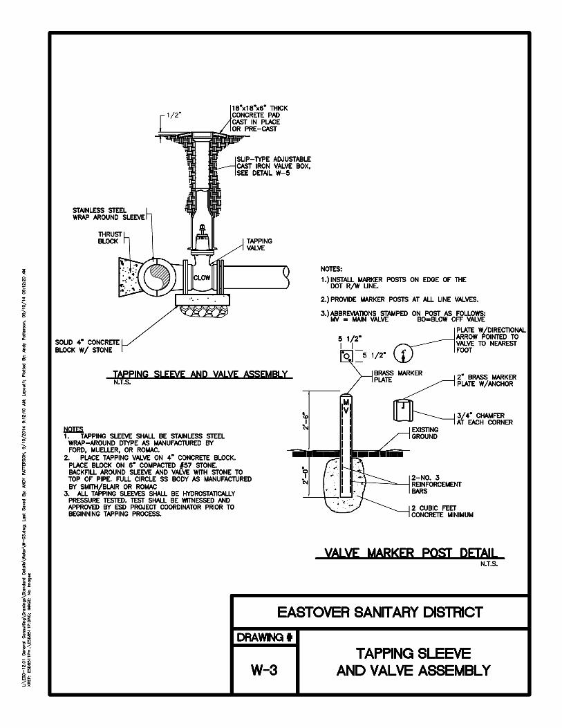
A. Stainless Steel Fully Gasketed Wrap Around Tapping Sleeve: Tapping sleeve body, strap, flange, lifter bar studs, nuts and washers shall all be constructed of 18-8 Type 304 stainless steel. Welds shall be fully passivated. Nuts and washers shall be fluorocarbon coated. Outlet pipe shall be constructed of Schedule 5, 18-8 Type 304 stainless steel. Tapping Sleeve flange shall conform to AWWA C207 Class D-ANSI 150 lb. drilling. Boltholes shall straddle pipe centerline. Tapping sleeve shall be equipped with a ¾” brass test plug. The outlet gasket shall be gridded virgin Buna-N compounded for water service per ASTM D2000. Tapping sleeve full gasket shall be gridded virgin SBR compounded for water service per ASTM D2000 and shall give 360-degree pipe coverage. Tapping Sleeves shall be NSF 61 certified. Stainless Steel Tapping Sleeves 4” through 8” shall have a minimum 200-psi working pressure rating. Sleeves

DS SECTION 1 - Water Distribution Page 1 -12
10” to 24” shall have a minimum 200-psi working pressure rating. Stainless Steel Wrap Around Tapping Sleeves shall be manufactured by Smith-Blair, ROMAC, or approved equal.
B. Mechanical Joint Tapping Sleeves: Tapping sleeve to be manufactured from gray cast iron meeting or exceeding ASTM A126 Grade B or ductile iron meeting ASTM A536 Grade 65-45-12 (outlet sizes 14" and larger). Side flange seals shall be of the O-ring type of either round, oval or rectangular cross-sectional shape. Tapping sleeves to be used in conjunction with a mating tapping valve from same manufacturer. Outlet flange of sleeve to be counterbored per MSS SP-60 for true alignment of tapping valve and tapping machine. Sizes of outlet to be available through equal opening of sleeve diameters up to 24". Tapping sleeves shall be Mueller mechanical joint, Mueller Outlet Seal, American Uniseal or Kennedy Square Seal. All sleeves shall have a minimum of 200-psi working pressure. All taps shall be of 200 psi working pressure. All taps shall be machine drilled – no burned taps will be allowed. All sleeves are to include the end joint accessories and split glands necessary to assemble sleeve to pipe. MJ bolts and nuts are to conform to ANSI/AWWA C111/A21.11-95. No special tools other than standard socket wrench to be required for assembly of sleeve to main. Sleeve shall be coated with asphaltic varnish per Federal Specification TT-V-51, Military Specification MIL C-450, or equal.
C. Resilient Seated Tapping Valves: Tapping Valves shall be resilient-seated gate valves
conforming to AWWA C509 and shall be NSF 61 certified. The body and bonnet shall be coated both interior and exterior with a fusion bonded heat cured thermo setting material meeting all application and performance requirements of AWWA C550. The minimum design working pressure shall be 200 psi for tapping valves up to 12” and 150 psi for valves larger than 12”. Resilient seated gate valves shall be manufactured by Mueller, or an approved equal.
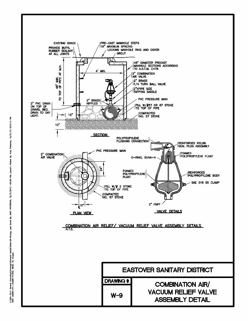
Combination Air Valves Combination air release valves shall be installed at high points in the water main as indicated by the plans in order to release air in the main as the main is filling and allow air to enter the system when draining or subject to negative pressure. The valve shall also release an accumulation of air when the system is under pressure. Combination air release valves shall be manufactured to meet or exceed the requirements of ANSI/AWWA C512-07 or latest revision and shall be NSF 61 certified. The valve shall operate through a compound lever system that will seal both the pressure orifice and the air vacuum orifice simultaneously. This lever system shall permit a ¼” orifice to release an accumulation of air from the valve body at a capacity of 98 cfm of air and pressure of 200 psig. The function of the lever system shall also permit a positive disengagement of the main valve from the large orifice. As the float drops and pressure decreases, the disengagement shall be immediate and not be limited to the initial draw of a vacuum. The valves shall be 2” NPT screwed or ANSI Class 125 flanged inlet connection and shall be cast iron body, top and inlet flange (where required), stainless steel float and trim with Buna-n seat. Valves, which operate the pressure plunger via a single lever and fulcrum, will not be acceptable. A protectop shall be supplied to prevent debris from entering the
DS SECTION 1 - Water Distribution Page 1 -13
outlet of the valve. Each valve assembly shall include a 2” NRS, solid disc, inside screw bonnet gate valve with a 200 WOG pressure rating and conforming to Federal Specification MSS SP-80. Each valve assembly shall be installed in a manhole as shown on the detail sheet in the plans. The Combination Air Valves shall be manufactured by Crispin, Cla-Val, or Val-Matic. Indicator Posts UL 789 and as detailed on the project drawings. Provide for gate valves where indicated. Valve Boxes Valve boxes shall be "slip-type" made of close-grained, gray cast iron metal painted with a protective asphaltic coating. Construction shall be in three pieces as follows: The lower of base pieces, which shall be flanged at the bottom, the upper part which shall be flanged on the lower end, and of such size as to telescope over the lower part, the upper end being constructed in the form of a socket to receive the cap or cover; and the cover or cap shall have cast on the upper surface, in raised letters, the word "WATER". All valve boxes shall be equal in quality and workmanship to those manufactured by Sigma Corporation (VB-462), Tyler Union (6855 Series), Star Pipe Products (VB-0004), or an approved equal. Valve box shall have a 3/8" hole drilled in the upper part 4” to 6” from the top of the box to accommodate 1/4" x 1-1/2" galvanized bolt for securing tracer wire. Valve box protector rings shall be installed to protect valve boxes located outside pavements (i.e. roadway shoulders). Tracer Wire for Nonmetallic Piping A continuous "detectable" identification wire shall be installed of all non-ferrous piping. The wire shall be 12 gauge single strand, copper coated wire that is suitable for underground use. Attach wire to top of pipe in such manner that it will not be displaced during construction operations. All wire splices shall use a Snake Bite (SCB-01SR) corrosion proof connector. The wire shall be "stubbed" into valve boxes and secured such that a "direct"/conductive metal detector may be used to trace the pipe. Detectable Underground Warning Tape Warning tap shall be installed above all water mains 12-18” below finished grade. The Warning Tape shall be 3” wide aluminum core, 5mil low density polyethylene, APWA Blue and read “CAUTION BUIRED WATER LINE BELOW”. WATER SERVICES (1-INCH)

DS SECTION 1 - Water Distribution Page 1 -14
Tapping Saddles Tapping saddles shall be 1” cc double strap stainless steel and provide full support around the circumference of the pipe with a designed in safeguard against over-tightening to prevent deforming the pipe. All parts of the saddle shall be constructed of corrosive resistant bronze or galvanized malleable iron including bolts and nuts required to assemble. Only saddles designed specifically for the type water main pipe used shall be allowed. Threads shall be AWWA standard cc tapered. Tapping saddles shall be manufactured by Ford. Direct taps to the water main shall not be allowed and there shall be not less than 5-feet of separation between taps where multiple taps are made. Corporation Stops Keyed or Ball Corporation stops shall be of bronze construction with AWWA inlets by Compression CTS in SS insert and a minimum 1” (inlet and outlet). Inlet threads shall be AWWA Standard Taper cc. Outlets will be IP threads with a brass compression-fitting adapter for PE (CTS) service tubing. Corporation stops shall be manufactured by Ford. Polyethylene (PE) Pipe for Service Laterals 1” pipe for service lines shall be PE Pipe of Copper Tubing Size (CTS) with a 200 psi pressure rating. Fittings shall be compression type brass fittings. A 12 gauge tracer wire shall be laid with the service piping and extend into the meter box with a minimum of 6” of wire wrapped around the meter valve.
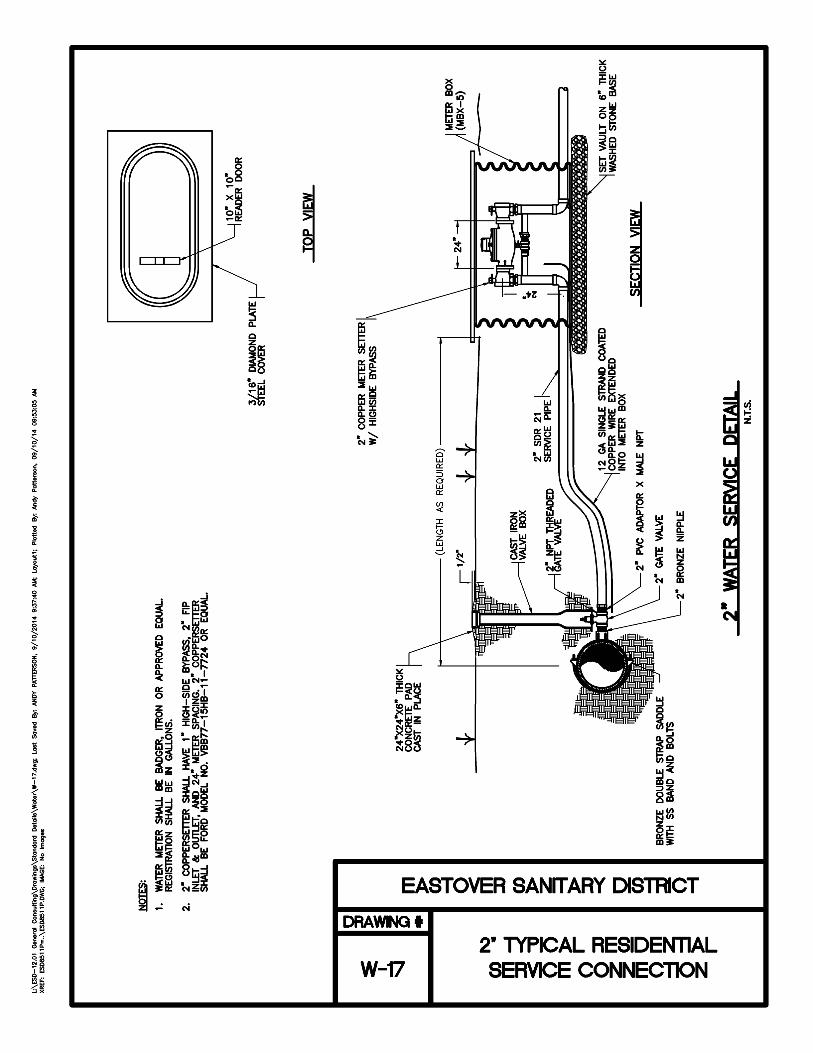
Copper Meter Yokes Copper Meter Yokes shall be 5/8” x 3/4” x 9” in height and shall include an integral Ball Angle Meter Valve and dual check valve. Copper Meter Yokes shall be manufactured by Ford. Meter Boxes Meter Boxes shall be constructed of cast iron. Cast Iron Boxes shall be made in two pieces, i.e. box and cover. The box shall be a minimum of 18" deep by 20" long by 10" wide. The meter boxes shall rest on a brick base on all four sides of the box with a minimum of 3” of washed stone in the bottom of the meter box. The meter box shall be equipped with a pre-drilled 1-7/8” hole drilled in the top of the box and shall be compatible with AMR Meters. Meter boxes shall be MBX-1 for ¾” or 1” services and MBX-5 for 1 ½” or 2” services. Cast iron boxes shall be Dewey Brothers, Ford Meter Box Company, Opelike Foundry Company or equal. Cut-off Valve On the Customer side of the meter box a 200 psi rated ball valve shall be supplied and enclosed in a separate box for the purpose of the customer’s ability to cut off water to the customer. The customer shall not have access to ESD’s meter box. Teflon Tape Teflon tape shall be used on all threaded connections to reduce the possibility of leaking joints.
Water Meters Water Meters shall be supplied by Eastover Sanitary District. Spacers for domestic/iRR will be provided by ESD. Meter 2” and larger shall be supplied by the contractors/developer and shall be approved by ESD prior to installation. Meters and registers shall be compatible with the ITRON remote read system.

DS SECTION 1 - Water Distribution Page 1 -15
PART 3 EXECUTION INSTALLATION OF PIPELINES General Requirements for Installation of Pipelines These requirements shall apply to all pipeline installation except where specific exception is made in the "Special Requirements..." paragraphs. The Contractor shall furnish all labor, tools, equipment and other incidentals required for the construction of the water distribution system as shown on the drawings and as specified herein. The work shall include laying pipe and setting fittings, valves, hydrants, and services, pressure testing and sterilization of the water distribution system. Materials shall be as specified in previous sections of these specifications.
Location of Water Lines Terminate the work covered by this section at the edge of the existing NCDOT or street right of way, unless otherwise indicated. Do not lay water lines in the same trench with gas lines, fuel lines or electric wiring. Minimum requirements for proximity of new water mains with sanitary sewer piping shall be as per NCAC Title 15A, Subchapter 18C “Water Supplies”, Section .0906 and as follows:
A. Water Piping Installation Parallel With Sewer Piping
1. Normal Conditions: Lay water piping at least 10 feet horizontally from a sewer or sewer
manhole whenever possible. Measure the distance edge-to-edge.
2. Unusual Conditions: When local conditions prevent a horizontal separation of 10 feet, the water piping may be laid closer to a sewer or sewer manhole provided that:
(a) The bottom (invert) of the water piping shall be at least 18 inches above the top
(crown) of the sewer piping. (b) Where this vertical separation cannot be obtained, the sewer piping shall be
constructed of AWWA-approved water ductile iron pipe and pressure tested in place without leakage prior to backfilling.
(c) The sewer manhole shall be of watertight construction and tested in place.
B. Installation of Water Piping Crossing
1. Normal Conditions: Water piping crossing above sewer piping shall be laid to provide a
separation of at least 18 inches between the bottom of the water piping and the top of the sewer piping.
2. Unusual Conditions: When local conditions prevent a vertical separation described
above, use the following construction:
DS SECTION 1 - Water Distribution Page 1 -16
(a) Sewer piping passing over or under water piping shall be constructed of AWWA-approved ductile iron water piping, pressure tested in place without leakage prior to backfilling.
(b) Water piping passing under sewer piping and storm sewer piping shall, in addition,
be protected by providing a vertical separation of at least 18 inches between the bottom of the sewer piping and the top of the water piping; adequate structural support for the sewer piping to prevent excessive deflection of the joints and the settling on and breaking of the water piping; and that the length, minimum 20 feet, of the water piping be centered at the point of the crossing so that joints shall be equidistant and as far as possible from the sewer piping and needs to be Ductile Iron.
(c) Sewer Piping or Sewer Manholes: No water piping shall pass through or come in contact with any part of a sewer manhole.
Earthwork Perform earthwork operations in accordance with Section 3, “Earthwork and Borings for Utilities.” All Ductile Iron and Polyvinyl Chloride (PVC) pipe shall be installed in Type 3 embedment. The pipe shall be bedded in 4” of loose soil. Backfill shall be lightly consolidated to the top of the pipe. Loose soil is defined as native soil excavated from the trench, free of rocks, foreign materials and frozen earth. Compaction test shall be performed at 500lf intervals. Results of the compaction test shall be provided to ESD.
Pipe Laying and Jointing Remove fins and burrs from pipe and fittings. Before placing in position, clean pipe, fittings, valves, and accessories, and maintain in a clean condition. Provide proper facilities for lowering sections of pipe into trenches. Do not under any circumstances drop or dump pipe, fittings, valves, or any other water line material into trenches. Cut pipe accurately to length established at the site and work into place without springing or forcing. Replace by one of the proper length any pipe or fitting that does not allow sufficient space for proper installation of jointing material. Blocking or wedging between bells and spigots will not be permitted. Lay bell-and-spigot pipe with the bell end pointing in the direction of laying. Grade the pipeline in straight lines; avoid the formation of dips and low points. Support pipe at proper elevation and grade. Secure firm, uniform support. Wood support blocking will not be permitted. Lay pipe so that the full length of each section of pipe and each fitting will rest solidly on the pipe bedding; excavate recesses to accommodate bells, joints, and couplings. Provide anchors and supports where necessary for fastening work into place. Make proper provision for expansion and contraction of pipelines. Keep trenches free of water until joints have been properly made. At the end of each workday, close open ends of pipe temporarily with wood blocks or bulkheads. Do not lay pipe when conditions of trench or weather prevent installation. Depth of cover over top of pipe shall not be less than 3.5 feet.

DS SECTION 1 - Water Distribution Page 1 -17
Installation of Tracer Wire Install a continuous length of tracer wire for the full length of each run of nonmetallic pipe. Attach wire to top of pipe in such manner that it will not be displaced during construction operations. Tracer wire should be fixed to pipe. Warning Tape shall also installed above the pipe installation from 12-18” below finished grade. The Warning Tape will indicate the presence of the utility. Connections to Existing Water Lines Make connections to existing water lines after approval is obtained and with a minimum interruption of service on the existing line. Make connections to existing lines under pressure as indicated. In no case shall the Contractor shut off the water or operate the fire hydrants or gate valves of the existing distribution system without the expressed permission of ESD and coordination with ESD. In case it becomes necessary to delay the cut-off, such instructions shall be given and obeyed without recourse. In making connections to the existing distribution system, valves shall be set as shown on the plan, or at such designated place as ESD may direct. If due to unforeseen conditions, these locations have to be changed or additional valves or fittings added, the Contractor shall install the valves or fittings at the new locations at the unit price scheduled in the bid items. ESD shall be present at all connections to existing water main, notice shall be provided prior to connections at least 48 hours in advance of the connections.
Special Requirements for Installation of Water Mains Installation of Ductile-Iron Piping Unless otherwise specified, install pipe and fittings in accordance with paragraph entitled "General Requirements for Installation of Pipelines" and with the requirements of AWWA C600 for pipe installation, joint assembly, valve-and-fitting installation, and thrust restraint.
Pipe Deflection Table for Push On Joint DIP
Nominal Pipe Size
O.D. (inches)
Maximum Deflection
Angle (degrees)
Maximum Deflection per Joint (inches)
18 ft joint 20 ft joint
3 3.96 5 19 21
4 4.8 5 19 21
6 6.9 5 19 21
8 9.05 5 19 21
10 11.1 5 19 21
12 13.2 5 19 21
* Source - Griffin Pipe Products Co.

DS SECTION 1 - Water Distribution Page 1 -18
A. Push-On Joints: Make push-on joints with the gaskets and lubricant specified for this type joint; assemble in accordance with the applicable requirements of AWWA C600 for joint assembly. Clean gasket and spigot and inside of bell thoroughly to remove all dirt and other foreign matter. Insert gasket furnished by the pipe manufacturer into the gasket seat in the bell. Gasket shall be properly seated in the grooves provided in the pipe bell. Using a non-toxic vegetable soap, apply a film by hand to the inside surface of the gasket that comes into contact with the entering pipe and to the first 1" of the spigot end of the entering pipe. Use only lubricant specified by the pipe manufacturer. Align entering pipe with the bell to which it is to be joined. Enter the spigot end into the bell until it just makes contact with the gasket. Apply sufficient pressure to force the spigot end past the gasket up to solid contact with the bell. When it is necessary to field cut pipe with rubber gaskets, chamfer the cut end 1/8 inch x 30 degrees before inserting into a rubber gasket bell.
B. Mechanical Joints: Make mechanical joints with the gaskets, glands, bolts, and nuts specified
for this type joint; assemble in accordance with the applicable requirements of AWWA C600 for joint assembly and the recommendations of Appendix A to AWWA C111/A21.11. Clean last 8" outside the spigot, and the inside of the bell of mechanical joint pipe or fitting to remove oil, grit, tar (other than standard coating) and other foreign matter from the joint and then paint area clean with an approved lubricating solution. The ductile iron gland shall then be slipped on the spigot end of the pipe with the extension of the gland toward the socket or bell end. The rubber gasket shall be painted with the soap solution and placed on the spigot end with thick edge toward the gland. Push entire section of pipe forward to seat spigot end in the bell. Press gasket into place within the bell, being careful to have the gasket evenly located around the entire joint. Move ductile iron gland along the pipe into position for bolting, insert all bolts, and screw nuts up tightly with fingers. Tighten all nuts with a suitable (preferably torque-limiting) wrench. Tighten nuts that are spaced 180 degrees apart alternately in order to produce equal pressure on all parts of the gland.
C. Flanged Joints: Make flanged joints with the gaskets, bolts, and nuts specified for this type
joint. Make flanged joints up tight; avoid undue strain on flanges, fittings, valves, and other accessories. Align bolt holes for each flanged joint. Use full size bolts for the boltholes; use of undersized bolts to make up for misalignment of boltholes or for any other purpose will not be permitted. Do not allow adjoining flange faces to be out of parallel to such degree that the flanged joint cannot be made watertight without overstraining the flange. When flanged pipe or fitting has dimensions that do not allow the making of a proper-flanged joint as specified, replace it by one of proper dimensions. Use set screwed flanges to make flanged joints where conditions prevent the use of full-length flanged pipe and assemble in accordance with the recommendations of the setscrewed flange manufacturer.
D. Sleeved Joints: Assemble joints made with sleeve-type mechanical couplings in accordance
with the recommendations of the coupling manufacturer.
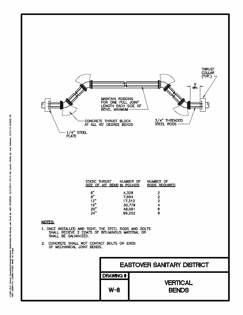
E. Fittings: Fittings shall be installed where and as shown on the plans or as directed by ESD. All bends (1/16 to 1/4), y-branches, plugs and all other fittings requiring such shall be sufficiently backed, blocked, or braced to preclude the possibility of their blowing off the main.

DS SECTION 1 - Water Distribution Page 1 -19
F. Pipe Anchorage: Provide concrete thrust blocks (reaction backing) for pipe anchorage. Thrust blocks shall be in accordance with the requirements of AWWA C600 for thrust restraint. Use concrete, ASTM C 94, having a minimum compressive strength of 2,500 psi at 28 days; or use concrete of a mix not leaner than one part cement, 2 1/2 parts sand, and 5 parts gravel, having the same minimum compressive strength. Blocking shall be formed and placed in such a manner that the pressure to be exerted at the point of blocking shall be transferred to firm, undisturbed earth at a maximum load of 2,000 lbs, per square foot. The Contractor shall insure that blocking at all tees, bends, plugs, etc., shall be sufficient to contain all pressure exerted by the pipe up to 200 psi hydraulic pressure within the pipe, e.g., pressure at plug = 200 x (area of pipe in inches). Blocking shall be constructed as shown on the detail sheet contained in the project plans. The Contractor shall also be responsible for any damage or repairs caused by blowouts of any insufficiently blocked pipe.
Installation of Valves and Hydrants
A. Installation of Valves: Install gate valves, AWWA C500 and UL 262, in accordance with the requirements of AWWA C600 for valve-and-fitting installation and with the recommendations of the Appendix ("Installation, Operation, and Maintenance of Gate Valves") to AWWA C509. Make and assemble joints to gate valves and check valves as specified for making and assembling the same type joints between pipe and fittings. Valves shall be set and anchored with steel bars and concrete as shown on the detail sheet contained in the project detailed drawings. All valves set by the Contractor shall include a cast iron or ductile iron valve box set to grade encircled and protected by a precast concrete donut.
B. Installation of Hydrants: Install hydrants in accordance with AWWA C600 for hydrant
installation and as indicted. Make and assemble joints as specified for making and assembling the same type joints between pipe and fittings. Install hydrants with 4 1/2 inch connections facing the adjacent paved surface. Fire hydrants shall be set where shown on the plans or as directed by ESD. The hydrants shall be set upon a bed of compacted crushed stone at least thirty-inches (30”) square by ten inches (10”) in depth. Each hydrant and hydrant valve and associated piping shall be restrained by the use of a MJ retaining gland (Mega Lug or approved equal) from the hydrant tee to the hydrant barrel. There shall be no concrete or threaded rods used in the hydrant installations. All components shall be securely restrained and anchored detail contained in the project drawing details. When the hydrant is backfilled, seven cubic feet of #57 stone shall be placed around the hydrant to a point just above the drain holes of the hydrant.
C. Location of Hydrants: All fire hydrants shall be installed on a minimum 6-inch waterline. . Generally, fire hydrants should be located at street intersections and property corners. Intermediate fire hydrant placement shall be located at property corners along the R/W line. Fire hydrants shall be located no more than 1,000 feet apart and at a maximum of 500 feet from any lot or unit within a subdivision. Fire Hydrants shall be installed in locations that maximize water quality operations as directed by ESD.
Installation of Water Service Piping Location
DS SECTION 1 - Water Distribution Page 1 -20
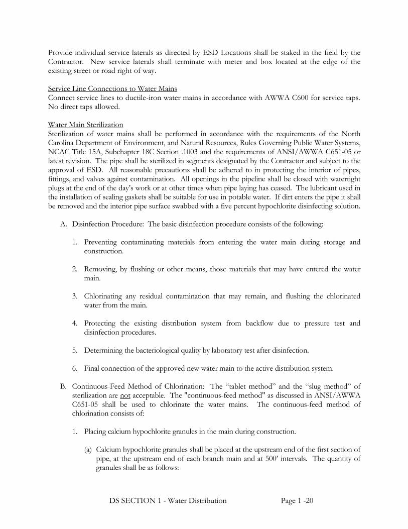
Provide individual service laterals as directed by ESD Locations shall be staked in the field by the Contractor. New service laterals shall terminate with meter and box located at the edge of the existing street or road right of way. Service Line Connections to Water Mains Connect service lines to ductile-iron water mains in accordance with AWWA C600 for service taps. No direct taps allowed. Water Main Sterilization Sterilization of water mains shall be performed in accordance with the requirements of the North Carolina Department of Environment, and Natural Resources, Rules Governing Public Water Systems, NCAC Title 15A, Subchapter 18C Section .1003 and the requirements of ANSI/AWWA C651-05 or latest revision. The pipe shall be sterilized in segments designated by the Contractor and subject to the approval of ESD. All reasonable precautions shall be adhered to in protecting the interior of pipes, fittings, and valves against contamination. All openings in the pipeline shall be closed with watertight plugs at the end of the day’s work or at other times when pipe laying has ceased. The lubricant used in the installation of sealing gaskets shall be suitable for use in potable water. If dirt enters the pipe it shall be removed and the interior pipe surface swabbed with a five percent hypochlorite disinfecting solution.
A. Disinfection Procedure: The basic disinfection procedure consists of the following: 1. Preventing contaminating materials from entering the water main during storage and
construction.
2. Removing, by flushing or other means, those materials that may have entered the water main.
3. Chlorinating any residual contamination that may remain, and flushing the chlorinated
water from the main.
4. Protecting the existing distribution system from backflow due to pressure test and disinfection procedures.
5. Determining the bacteriological quality by laboratory test after disinfection.
6. Final connection of the approved new water main to the active distribution system.
B. Continuous-Feed Method of Chlorination: The “tablet method” and the “slug method” of
sterilization are not acceptable. The "continuous-feed method" as discussed in ANSI/AWWA C651-05 shall be used to chlorinate the water mains. The continuous-feed method of chlorination consists of: 1. Placing calcium hypochlorite granules in the main during construction.
(a) Calcium hypochlorite granules shall be placed at the upstream end of the first section of pipe, at the upstream end of each branch main and at 500’ intervals. The quantity of granules shall be as follows:

DS SECTION 1 - Water Distribution Page 1 -21
Pipe Diameter (Inches) Calcium Hypochlorite Granules (Ounces) 4 0.5 6 1.0 8 2.0 12 4.0 16 & Larger 8.0
2. Completely filling the main to eliminate air pockets.
(a) The initial filling shall be at a rate such that water within the main will flow at a velocity no greater than 1 foot per second (fps). Precautions shall be taken to insure that air pockets are eliminated.
3. Flushing the main to remove particulates.
(a) Once the main has been completely filled with potable water and all air expelled, the main shall be flushed to remove particulates at a rate of not less than 2.5 fps. The discharge point for the flushing operation shall be coordinated with ESD. In lieu of flushing the Contractor may choose this time to clean the water main as described in the following paragraph (b) entitled “Cleaning of Water Mains”
(b) Cleaning of Water Mains: The Contractor shall clean all new water mains installed in this project by using a flexible polyurethane swab (“pig”). The pig shall be of 5 lb/cf density polyurethane of the proper size for the water mains being cleaned. The pig shall be inserted into the first section of pipe and shall remain there until construction of that line segment is completed. Cleaning shall be accomplished by propelling the pig down the water main by system pressure to the exit point as determined by the Contractor. After the pig exits the pipe, flushing shall be performed until the water is completely clear and the turbidity level is less than 1.0 NTU. Cleaning of water mains with diameters larger than 12 inches or water mains that utilize butterfly valves shall be performed in the same manner excepting that the Contractor will be required to pig the main from valve to valve or in a manner acceptable to the Engineer and the Owner. Flushing on small diameter and shorter line segments may be allowed at the approval of ESD.
4. Filling the main with super-chlorinated potable water so that after a 24-hour holding period
in the main there will be a free chlorine residual of not less than 20 parts per million (ppm).
(a) The procedure for chlorinating the main shall begin with water being made to flow into the newly installed water main at a constant, measured rate. In the absence of a meter the rate may be approximated by a method approved by ESD (A hydrant meter is recommended). At a point not more than 10’ downstream from the beginning of the new main, water entering the new main shall receive a dose of chlorine fed at a constant rate such that the water will have not less than 50-ppm free chlorine. The chlorine concentration should be measured at regular intervals using appropriate chlorine test kits. Chlorine application shall not cease until the entire main (or isolated portion

DS SECTION 1 - Water Distribution Page 1 -22
thereof) is filled with heavily chlorinated water. The chlorinated water shall be retained in the main for at least 24 hours during which time all valves and hydrants in the treated section shall be operated to ensure disinfection of the appurtenances. At the end of this 24-hour period, the treated water in all portions of the main shall have a residual of not less than 20-ppm free chlorine.
(1) Chlorine Application: The forms of chlorine that may be used in the disinfection
operations are liquid chlorine conforming to ANSI/AWWA B301, sodium hypochlorite solution conforming to ANSI/AWWA B300 and calcium hypochlorite granules or tablets conforming to ANSI/AWWA B300. Liquid Chlorine shall be used only in combination with appropriate gas-flow chlorinators and ejectors and under the direct supervision of a person who is familiar with the physiological, chemical, and physical properties of liquid chlorine. Liquid chlorine may be used only when appropriate safety practices are observed to protect working personnel and the public. Sodium Hypochlorite Solution and Calcium Hypochlorite Granules used to form a solution may be applied to the water to be chlorinated with a gasoline or electrically powered chemical-feed pump designed for feeding chlorine solutions. Feed lines shall be able to withstand the corrosion caused by the concentrated chlorine solutions and the maximum pressures created by the pump.
5. Final flushing of the water main to remove super-chlorinated water.
(a) After the applicable retention period, heavily chlorinated water should not remain in
prolonged contact with pipe. In order to prevent damage to the pipe lining or corrosion damage to the pipe itself, the heavily chlorinated water shall be flushed from the main until chlorine measurements show that the concentration in the water leaving the main is no higher than that generally prevailing in the system or is acceptable for domestic use. The environment to which the chlorinated water is to be discharged shall be inspected. If there is any question that the chlorinated discharge will cause damage to the environment, then a reducing agent shall be applied to the water to be wasted to neutralize thoroughly the chlorine residual remaining in the water. (See AWWA C-651 Appendix B for neutralizing chemicals). Where necessary, Federal, State and local regulatory agencies should be contacted to determine special provisions for the disposal of heavily chlorinated water. This effort shall be coordinated fully by the by Contractor.
C. Bacteriological Tests: Twenty-four hours after final flushing to remove excess chlorine,
representative water samples shall be taken from each water line segment for bacteriological quality tests in accordance with "Standard Methods for the Examination of Water and Wastewater". At least one sample shall be collected from every water main segment including one set from the end of the line and at least one set from each branch and sampling shall not exceed 1,000 ft of straight run of pipe. No portion of the system shall be placed in operation until the tests are approved. If the presence of coliform bacteria is detected in the water samples, the section of pipe shall be re-sterilized and additional samples shall be taken. If, during construction, trench water has entered the main, or if in the opinion of ESD, excessive quantities of dirt or debris have entered the main, bacteriological samples may be required at more frequent intervals. Furthermore at the discretion of ESD samples shall be taken of water that has stood in the main for at least 72

DS SECTION 1 - Water Distribution Page 1 -23
hours after final flushing has been completed. If the initial disinfection fails to produce satisfactory bacteriological samples, the main may be re-flushed and shall be resampled. If check samples show the presence of coliform organisms, then the main shall be re-chlorinated by the continuous-feed of chlorination until satisfactory results are obtained.
All bacteriological tests from each tested segment of water main shall be delivered to
and tested by a NC Department of Health and Human Service Approved Laboratory. Approved or Certified municipal and private laboratories can be found on the following web-address.
http://slphreporting.ncpublichealth.com/EnvironmentalSciences/Certification/CertifiedLaboratory.asp .
FIELD QUALITY CONTROL Field Tests and Inspections ESD will conduct field inspections and witness field tests specified in this section. The Contractor shall perform field tests, and provide labor, equipment, and incidentals required for testing. The Contractor shall produce evidence, when required, that any item of work has been constructed in accordance with the drawings and specifications. Do not begin testing on any section of a pipeline where concrete thrust blocks have been provided until at least 5 days after placing of the concrete. Water for testing and sterilization may be purchased from ESD. Pressure and Leakage Testing Hydrostatic pressure and leakage testing for water mains and water service lines shall conform to ANSI/AWWA C600-10 or latest revision for ductile iron water main and ANSI/AWWA C605-11 or latest revision for polyvinyl chloride pipe. Leakage test may be performed at the same time and at the same test pressure as the pressure test. Pressure testing shall be performed on all pipe, valves, hydrants, and fittings. The test shall be conducted on line segments from shut valve to shut valve in segments not exceeding 2,000 linear feet. The Contractor shall provide a suitable pump for applying pressure and an accurate gauge for measuring the pressure and an Engineer approved method of determining volume of water used. All newly laid pipe and any isolated sections thereof shall be subject to a hydrostatic pressure of at least 1.5 times the working pressure at the point of testing or 200 psi (whichever is greater). At the same time the test pressure shall not be less than 1.25 times the working pressure at the highest point along the test section. The hydrostatic test shall be of at least two-hour duration. Removal of air shall be performed to the satisfaction of ESD through use of the air release valve assemblies (automatic and manual) and the fire hydrants. Prior to the pressure test, fill that portion of the pipeline being tested with water for a soaking period of not less than 24 hours. If determined necessary by ESD, the Contractor shall install additional air taps to be abandoned after all air removal at no additional cost to ESD. Leakage shall be defined as the quantity of water that must be supplied into the newly laid pipe or any isolated section thereof to maintain pressure within 5 psi (35 MPa or 0.35 bar) of the specified test pressure after the pipe has been filled with water and the air has been expelled. Leakage shall not be measured by a drop in pressure in a test section over a period of time. No installation will be accepted if the leakage is greater than that determined by the following formulas: When testing Ductile Iron Pipe:
DS SECTION 1 - Water Distribution Page 1 -24
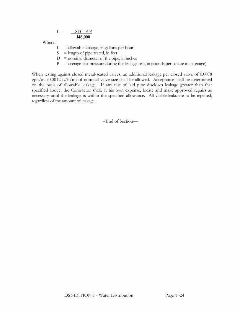
L = SD P 148,000
Where: L = allowable leakage, in gallons per hour S = length of pipe tested, in feet D = nominal diameter of the pipe, in inches P = average test pressure during the leakage test, in pounds per square inch gauge)
When testing against closed metal-seated valves, an additional leakage per closed valve of 0.0078 gph/in. (0.0012 L/h/m) of nominal valve size shall be allowed. Acceptance shall be determined on the basis of allowable leakage. If any test of laid pipe discloses leakage greater than that specified above, the Contractor shall, at his own expense, locate and make approved repairs as necessary until the leakage is within the specified allowance. All visible leaks are to be repaired, regardless of the amount of leakage.
--End of Section—

DS - SECTION 2 – Earthwork and Borings for Utilities Page 3 - 1
DETAILED SPECIFICATIONS
SECTION 2: EARTHWORK AND BORINGS FOR UTILITIES
PART 1 GENERAL REFERENCES
The publications listed below form a part of this specification to the extent referenced. The publications are referred to in the text by the basic designation only and Latest Revisions shall be applicable to all references.
AMERICAN SOCIETY FOR TESTING AND MATERIALS (ASTM)
ASTM A139 Standard Specification for Electric-Fusion (Arc)-Welded Steel Pipe
ASTM D698 Laboratory Compaction Characteristics of Soil Using
Standard Effort (12,400 ft-lbf/ft (600 kN-m/m))
ASTM D1140 Amount of Material in Soils Finer Than the No. 200 (75-Micrometer) Sieve
ASTM D1557 Laboratory Compaction Characteristics of Soil Using
Modified Effort (56,000 ft-lbf/ft (2,700 kN-m/m))
ASTM D2487 Standard Classification of Soils for Engineering Purposes (Unified Soil Classification System)
ASTM D4253 Maximum Index Density of Soils Using a Vibratory Table
ASTM D4254 Minimum Index Density and Unit Weight of Soils and
Calculation of Relative Density
ASTM D4318 Liquid Limit, Plastic Limit, and Plasticity Index of Soils
ASTM F1962 Standard Guide for Use of Maxi-Horizontal Directional
Drilling for Placement of Polyethylene Pipe or Conduit
Under Obstacles, Including River Crossings
CORPS OF ENGINEERS (COE)
COE EM-385-1-1 Safety and Health Requirements Manual

DS - SECTION 2 – Earthwork and Borings for Utilities Page 3 - 2
DESIGN REQUIREMENTS Trenching The trench shall be dug to the required alignment and depth as shown on the plans or directed by ESD, and only so far in advance of the pipe laying as ESD shall permit. The width of the trench shall be kept at a minimum. The depth of the trench shall generally be sufficient to allow a minimum of four feet of cover over the top of the pipe. The bottom of the trench shall be shaped by hand and shall support the pipe for the entire length. It shall be the responsibility of the Contractor to provide adequate bearing for all pipe lines laid in uncertain soil conditions. If flooding, rain or other causes should soften the trench bottom, the unsuitable material shall be removed and replaced with suitable material properly shaped and tamped to grade. Horizontal Borings for Steel Casing Installation Procedures for boring shall be in accordance with the best-accepted methods of the construction and as shown on the plans and described in these specifications. Steel casing pipes installed under highways and railroads shall be bored as shown on the detail drawings. Casings will be installed of the type, size, and thickness as specified herein or on the detail drawings. Under Highways Contractor shall be responsible for notifying the Department of Transportation at least five days prior to any contemplated work and for securing any required permits for performing the work. All work shall be accomplished under the supervision of ESD and the District Engineer of the Department of Transportation or his authorized representative. Under Railroads All work on railroad rights of way shall be done under the supervision of the Chief Engineer of the railroad, or his authorized representative, who shall be notified at least 15 days before construction is begun. In addition, this work shall only be done in the presence of the authorized representative of the Chief Engineer, and no methods shall be used that, in the opinion of the representative, could be hazardous to the railway. Directional Borings Utilizing HDPE Pipe Directional boring is a method of trenchless construction using a surface launched steerable drilling tool controlled from a mobile drilling frame, and includes a field power unit, mud mixing system and mobile spoils extraction system. The drilling frame is sited and aligned to bore a pilot borehole that conforms to the planned installation of the main. The drilling frame is set back from an access pit that has been dug (typically at the location of a proposed manhole or other appurtenance) and a high-pressure fluidjet toolhead that uses a mixture of bentonite clay and water is launched. Pits are normally dug at the start point and endpoint of the proposed pipe installation and are used to align the toolhead, attach other equipment, and to collect and remove excess spoils. Using an electronic guidance system, the toolhead is guided through the soil to create a pilot borehole. Upon reaching the endpoint joint, the toolhead is removed and a reamer with the product pipe attached is joined to the drill string and pulled back through the borehole. In large diameter installations, pre-reaming of the borehole will usually be done prior to attaching the product pipe for the final pullback. A vacuum spoils extraction system removes any excess spoils generated during the installation. The connections, manholes or other appurtenances are then completed at both the start point and endpoint locations and the surface restored to its original condition.

DS - SECTION 2 – Earthwork and Borings for Utilities Page 3 - 3
Site Conditions for Directional Borings Drilling operations must not interfere with, interrupt or endanger surface and activity upon the surface. Contractor must comply with all applicable jurisdictional codes and OSHA requirements. When rock stratum, boulders, underground obstructions, or other soil conditions that impede the progress of drilling operations are encountered, the Contractor and Engineer shall review the situation and jointly determine the feasibility of continuing drilling operations. EARTHWORK DEFINITIONS Backfill Material used in refilling a cut, trench or other excavation. Cohesive Materials Soils classified by ASTM D2487 as GC, SC, ML, CL, MH, and CH. Materials classified as GM and SM will be identified as cohesive only when fines have a plasticity index greater than zero.
Cohesionless Materials Soils classified by ASTM D2487 as GW, GP, SW, and SP. Materials classified as GM and SM will be identified as cohesionless only when the fines have a plasticity index of zero. Compaction The process of mechanically stabilizing a material by increasing its density at a controlled moisture condition. "Degree of Compaction" is expressed as a percentage of the maximum density obtained by the test procedure described in ASTM D698 or ASTM D1557 for general soil types or ASTM D4253 or ASTM D4254 (Relative Density) for isolated cohesionless materials, abbreviated in this specification as "95 percent ASTM D698 maximum density." Granular Pipe Bedding A dense, well-graded aggregate mixture of sand, gravel, or crushed stone (mixed individually, in combination with each other, or with suitable binder soil) placed on a subgrade to provide a suitable foundation for pipe (NCDOT #57 or #67). Granular bedding material may also consist of poorly graded sands or gravels where fast draining soil characteristics are desired. Hard Material Weathered rock, dense consolidated deposits, or conglomerate materials (excluding man made materials such as concrete) which are not included in the definition of "rock" but which usually require the use of heavy excavation equipment, ripper teeth, or jack hammers for removal. In-Situ Soil Existing in place soil. Lift A layer (or course) of soil placed on top of subgrade or a previously prepared or placed soil in a fill or backfill.

DS - SECTION 2 – Earthwork and Borings for Utilities Page 3 - 4
Porous Fill A granular soil material having a large void ratio when placed and compacted, allowing a free flow of fluid to or from the surrounding soil, with no more than 5 percent of the material passing the No. 100 Sieve. Refill Material placed in excavation to correct overcut in depth. Rock Solid homogeneous interlocking crystalline material with firmly cemented, laminated, or foliated masses or conglomerate deposits, neither of which can be removed without systematic drilling and blasting, drilling and the use of expansion jacks or feather wedges, or the use of backhoe-mounted pneumatic hole punchers or rock breakers; also large boulders, buried masonry, or concrete other than pavement exceeding 1/2 cubic yard in volume. Removal of "hard material" will not be considered rock excavation because of intermittent drilling and blasting that is performed merely to increase production. Satisfactory Backfill Material Non-plastic soils as defined by ASTM D2487 such as SW, SM and SC free of rock or gravel larger than 3 inches in any dimension, debris, organic matter, waste, frozen material, muck, roots, vegetation, and other deleterious matter. Select Backfill (Borrow) Satisfactory material obtained from borrows areas or commercial sources used as backfill. Topsoil In natural or undisturbed soil formations, the fine-grained, weathered material on the surface or directly below any loose or partially decomposed organic matter. Topsoil may be a dark-colored, fine, silty, or sandy material with a high content of well-decomposed organic matter, often containing traces of the parent rock material. Gradation and material requirements specified herein apply to all topsoil references in this contract. The material shall be representative of productive soils in the vicinity. Unyielding Material Rock rib, ridge, rock protrusion, or soil with cobbles in the trench bottom requiring a covering of finer grain material or special bedding to avoid bridging in the pipe or conduit. Unsatisfactory Backfill Material In-Situ soil or other material, which can be identified as having insufficient strength characteristics or stability to carry intended loads in the trench without excessive consolidation or loss of stability. Also backfill material, which contains refuse, frozen material, large rocks, debris, soluble particles, and other material, which could damage the pipe or cause the backfill not to compact. Materials classified as PT, OH, or OL by ASTM D 2487 are unsatisfactory.
Unstable Material Material in the trench bottom, which lacks firmness to maintain alignment and prevent joints from separating in the pipe, conduit, or appurtenance structure during backfilling. This may be material otherwise identified as satisfactory which has been disturbed or saturated.

DS - SECTION 2 – Earthwork and Borings for Utilities Page 3 - 5
SUBMITTALS
Submit two (2) copies of the following to ESD for approval before beginning construction. Product Data
A. Steel Casings B. Carrier Pipe Support and Spacer C. Casing End Seals
D. Bentonite drilling mud products (for Directional Boring) information (MSDS); special
precautions necessary; method of mixing and application; and method of removing spoils.
E. HDPE pipe for Directional Boring shall conform to the requirements in Section 1 & 2 “WATER DISTRIBUTION” & “SANITARY SEWERAGE”.
Shoring and Sheeting Plan Describe materials of shoring system to be used. Indicate whether or not components will remain after filling or backfilling. Provide plans, sketches, or details along with calculations by a professional engineer registered in any jurisdiction. Indicate sequence and method of installation and removal. Dewatering Plan Describe methods for removing collected water from open trenches and diverting surface water or piped flow away from work area. Describe the basic components of the dewatering system proposed for use and its planned method of operation. Dewatering plan, as a minimum, shall address those requirements outlined in paragraph entitled "Drainage and Dewatering." Qualifications
Directional Boring Contractors Directional boring Contractors will have actively engaged in the installation of pipe using directional boring techniques for a minimum of three years. Field supervisory personnel employed by the Directional Boring Contractor will have at least three years experience in the performance of the work and tasks. Submit documentation indicating experience. Information must include, but not be limited to, date and duration of work, location, pipe information (i.e., length, diameter, depth of installation, pipe material, etc.), project owner information, (i.e., name, address, telephone number, contact person), and the contents handled by the pipeline (water, wastewater, etc.). Submit a list of field supervisory personnel and their experience with directional boring operations. At least one of the field supervisors listed must be at the site and be responsible for all work at all times when directional boring operations are in progress. Directional boring operations will not proceed until the resume(s) of the Contractor’s field supervisory personnel have been received and reviewed by ESD.
DS - SECTION 2 – Earthwork and Borings for Utilities Page 3 - 6
Drawings Directional Boring Working drawings and written procedure describing in detail the proposed method of installation. This will include, but not be limited to, size, capacity and setup requirements of equipment; location and siting of drilling and receiving pits; dewatering if applicable; method of fusion and type of equipment for joining pipe; type of cutting tool head; and method of monitoring and controlling line and depth. If the Contractor determines that modifications to the method and equipment as stated in the submittal is necessary during construction, the contractor will submit a plan describing such modifications, including the reasons for the modification. Test Reports Maximum Density and Compaction Tests Compaction Tests Submit within 5 days of test date.
REGULATORY REQUIREMENTS Materials and workmanship specified herein with reference to NC DOT State Standard shall be in accordance with the referenced articles, sections, and paragraphs of the standard except that contractual and payment provisions do not apply. DELIVERY, STORAGE, AND HANDLING Deliver and store materials in a manner to prevent contamination, segregation, freezing, and other damage. Store synthetic fiber filter fabric to prevent exposure to direct sunlight. CRITERIA FOR BIDDING Base bids on the following criteria:
A. Surface elevations are as indicated.
B. No pipes or other man-made obstructions, except those indicated, will be encountered. C. No prior subsurface investigation has been performed for this project. However, in
preparing the bid, the Contractor shall assume that "Rock" or "Hard Material" as defined in the paragraph entitled "Definitions", will likely be encountered.
D. The Contractor should be aware of the possibility of encountering material not suitable for
foundation or backfill material in the excavation for this project, defined as either "Unsatisfactory Material" or "Unstable Material" in the paragraph entitled "Definitions". Compensation for removal and replacement of an estimated volume of material not suitable for foundation or backfill is detailed in Part 4 of this specification.

DS - SECTION 2 – Earthwork and Borings for Utilities Page 3 - 7
Rock Excavation Rock excavation consists of the blasting and excavation and disposal of rock material in cut areas. Rock excavation shall be labeled as material that cannot be removed with normal construction equipment such as pan scrapers or bulldozers with “rippers”, and requires the construction practice of blasting.
A. Classification: Rock shall be defined as sandstone, limestone, flint, granite, quartzite, slate, or similar material in masses more than ½ cubic yard in volume or in ledges 4 inches or more in thickness that cannot be excavated with a 25 metric ton hydraulic excavator equipped with rock teeth on a 24-inch wide bucket. Should rock be encountered in two or more ledges, each ledge being not less than 3-inches thick and with interlaying strata of earth, clay or gravel not more than 12-inches thick in each stratum, the entire volume between the top ledge and the bottom of the bottom ledge will be classified as rock.
B. Construction Requirements: Blasting: The use of explosives shall be performed in strict
accordance with all Federal, State, County and local regulation and only after the approval of ESD. The Contractor shall be responsible for all damage caused by blasting operations. Suitable methods shall bee employed to confine all materials that may be displaced by blasting; i.e., prevent projectiles. When rock is encountered, all lines and grades will be held in accordance with the plans or adjusted only after approval of ESD. Rock shall be excavated within the same limits as that of earth except that the trench shall be made 6-inches deeper than if no rock were encountered. The lower 6-inches shall be filled with #67 stone or other equivalent material approved by ESD and compacted prior to installing pipe. When rock is encountered within the limits of construction, the Contractor shall notify ESD’s representative prior to any removal. Upon ESD’s authorization, the Contractor shall remove the rock. The Contractor shall not be paid for rock removed without prior approval from ESD.
PROTECTION Dewatering Plan Base site surface and subsurface conditions, available soil and hydrological data. Utilities Movement of construction machinery and equipment over pipes and utilities during construction shall be at the Contractor's risk. For work immediately adjacent to or for excavations exposing a utility or other buried obstruction, excavate by hand. Start hand excavation on each side of the indicated obstruction and continue until the obstruction is uncovered or until clearance for the new grade is assured. Support uncovered lines or other existing work affected by the contract excavation until ESD grants approval for backfill. Report damage to utility lines or subsurface construction immediately to ESD.

DS - SECTION 2 – Earthwork and Borings for Utilities Page 3 - 8
PRODUCTS SOIL MATERIALS Provide soil materials as specified below free of debris, roots, wood, scrap material, vegetable matter, refuse, soft unsound particles, ice, or other deleterious and objectionable materials. Backfill Bring trenches to grade as indicated on the drawings using material excavated on the site of this project unless deemed unfit for use as backfill by ESD. Replace unsuitable material with suitable material as defined in Paragraph 1.3.12 “Satisfactory Backfill Material”. This material will be considered unclassified and no testing other than for compaction will be required before use as backfill except that the liquid limit of the material cannot exceed 35 percent when tested in accordance with ASTM D4318, the plasticity index cannot exceed 12 percent when tested in accordance with ASTM D4318, and not more than 35 percent by weight can be finer that the No. 200 sieve when tested in accordance with ASTM D1140.
Pipe Bedding Ductile Iron and PVC Water Mains and Force Mains Pipe bedding shall be the same backfill using material excavated on site unless deemed unfit for use as backfill by ESD. Replace unsuitable material with suitable material as defined in Paragraph 1.3.12 “Satisfactory Backfill Material”. Material surrounding pipe shall have ½” maximum particle size. Ductile Iron and PVC Gravity Sewer Mains Pipe bedding shall consist of a 4” NCDOT #57 or #67 stone gravel base with stone continuing as backfill to a minimum of 6” over top of the pipe. Gravel Clean, coarsely graded natural gravel, crushed stone or a combination thereof identified as NCDOT #57 or NCDOT #67.
Topsoil Material Free of subsoil, stumps, rocks larger than 3/4 inch in diameter (with maximum 3 percent retained on 1/4 inch sieve), brush, weeds, toxic substances, and other material or substance detrimental to plant growth. Topsoil shall be a natural, friable soil representative of productive soils in the vicinity. Borrow (Select Backfill Material) Where excavated material is deemed unfit for use backfill, provide select backfill material meeting the definition described in Paragraph 1.2.12 “Satisfactory Backfill Material”. Obtain borrow materials in excess of those unfit from excavations specified herein from borrow areas specified by the Contractor and approved by ESD.
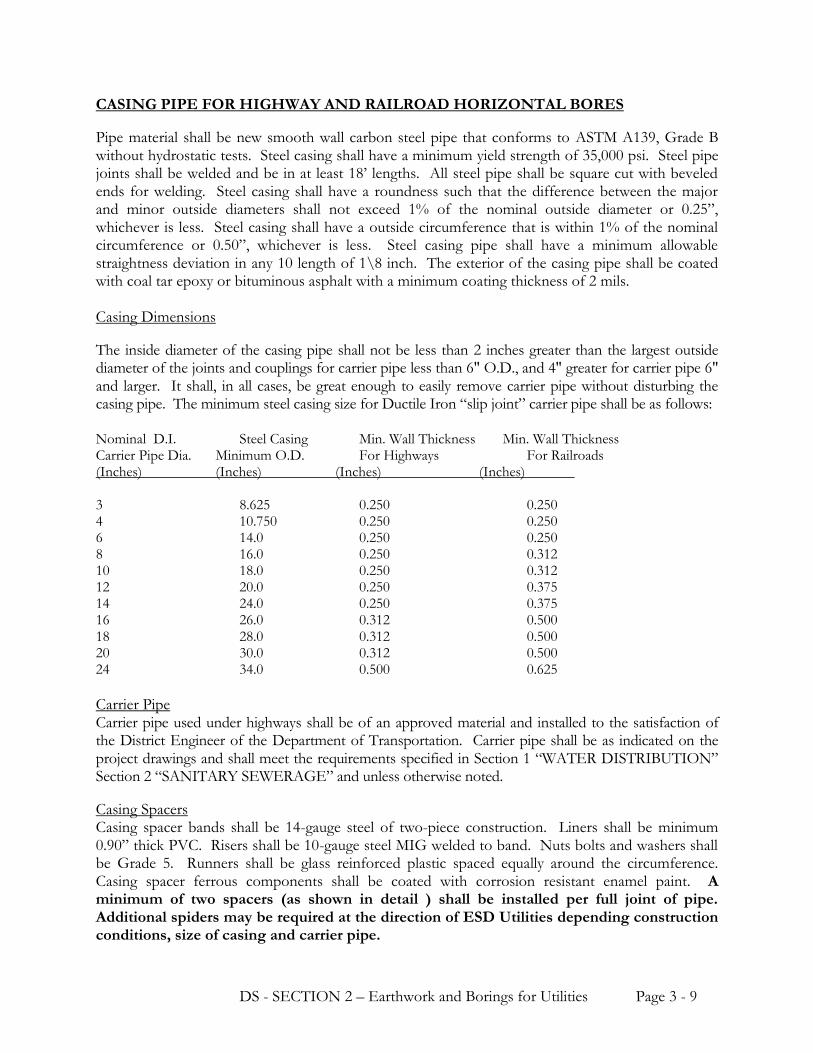
DS - SECTION 2 – Earthwork and Borings for Utilities Page 3 - 9
CASING PIPE FOR HIGHWAY AND RAILROAD HORIZONTAL BORES
Pipe material shall be new smooth wall carbon steel pipe that conforms to ASTM A139, Grade B without hydrostatic tests. Steel casing shall have a minimum yield strength of 35,000 psi. Steel pipe joints shall be welded and be in at least 18’ lengths. All steel pipe shall be square cut with beveled ends for welding. Steel casing shall have a roundness such that the difference between the major and minor outside diameters shall not exceed 1% of the nominal outside diameter or 0.25”, whichever is less. Steel casing shall have a outside circumference that is within 1% of the nominal circumference or 0.50”, whichever is less. Steel casing pipe shall have a minimum allowable straightness deviation in any 10 length of 1\8 inch. The exterior of the casing pipe shall be coated with coal tar epoxy or bituminous asphalt with a minimum coating thickness of 2 mils. Casing Dimensions
The inside diameter of the casing pipe shall not be less than 2 inches greater than the largest outside diameter of the joints and couplings for carrier pipe less than 6" O.D., and 4" greater for carrier pipe 6" and larger. It shall, in all cases, be great enough to easily remove carrier pipe without disturbing the casing pipe. The minimum steel casing size for Ductile Iron “slip joint” carrier pipe shall be as follows: Nominal D.I. Steel Casing Min. Wall Thickness Min. Wall Thickness Carrier Pipe Dia. Minimum O.D. For Highways For Railroads (Inches) (Inches) (Inches) (Inches) 3 8.625 0.250 0.250 4 10.750 0.250 0.250 6 14.0 0.250 0.250 8 16.0 0.250 0.312 10 18.0 0.250 0.312 12 20.0 0.250 0.375 14 24.0 0.250 0.375 16 26.0 0.312 0.500 18 28.0 0.312 0.500 20 30.0 0.312 0.500 24 34.0 0.500 0.625
Carrier Pipe Carrier pipe used under highways shall be of an approved material and installed to the satisfaction of the District Engineer of the Department of Transportation. Carrier pipe shall be as indicated on the project drawings and shall meet the requirements specified in Section 1 “WATER DISTRIBUTION” Section 2 “SANITARY SEWERAGE” and unless otherwise noted.
Casing Spacers Casing spacer bands shall be 14-gauge steel of two-piece construction. Liners shall be minimum 0.90” thick PVC. Risers shall be 10-gauge steel MIG welded to band. Nuts bolts and washers shall be Grade 5. Runners shall be glass reinforced plastic spaced equally around the circumference. Casing spacer ferrous components shall be coated with corrosion resistant enamel paint. A minimum of two spacers (as shown in detail ) shall be installed per full joint of pipe. Additional spiders may be required at the direction of ESD Utilities depending construction conditions, size of casing and carrier pipe.
DS - SECTION 2 – Earthwork and Borings for Utilities Page 3 - 10
Casing End Seals Casing End Seals shall be 1/8” thick synthetic rubber designed to withstand the weight of the backfill material. Stainless steel bands shall be used to attach the seals to the carrier and casing pipes. HDPE PIPE FOR DIRECTIONAL BORES HDPE pipe shall be accordance with requirements specified in Section 1, “WATER DISTRIBUTION” and “SANITARY SEWERAGE”. DRILLING FLUID FOR DIRECTIONAL BORES Drilling fluid will be a mixture of water and bentonite clay. The fluid will be inert.
PART 3 EXECUTION PROTECTION Shoring and Sheeting Provide shoring trench boxes and sheeting where required, according to subsurface conditions and depth of trench. In addition to Section 25 A and B of COE EM-385-1-1, include provisions in the shoring and sheeting plan that will accomplish the following:
a. Prevent undermining of pavements, foundations and slabs. b. Prevent slippage or movement in banks or slopes adjacent to the excavation.
c. Allow for the abandonment of shoring and sheeting materials in place in critical areas as the work is completed. In these areas, backfill the excavation to within 3 feet of the finished grade and remove the remaining exposed portion of the shoring before completing the backfill.
Drainage and Dewatering Plan for and provide the structures, equipment, and construction for the collection and disposal of surface and subsurface water encountered in the course of construction. Drainage Surface water shall be directed away from excavation and construction sites so as to prevent erosion and undermining of foundations. Diversion ditches, dikes and grading shall be provided and maintained as necessary during construction. Excavated slopes and backfill surfaces shall be protected to prevent erosion and sloughing. Excavation shall be performed so that the site and the area immediately surrounding the site and affecting operations at the site shall be continually and effectively drained.

DS - SECTION 2 – Earthwork and Borings for Utilities Page 3 - 11
Dewatering Groundwater flowing toward or into excavations shall be controlled to prevent sloughing of excavation slopes and walls, boils, uplift and heave in the excavation and to eliminate interference with orderly progress of construction. French drains, sumps, ditches or trenches will not be permitted within 3 feet of the foundation of any structure, except with specific written approval, and after specific contractual provisions for restoration of the foundation area have been made. Control measures shall be taken by the time the excavation reaches the water level in order to maintain the integrity of the in-situ material. While the excavation is open, the water level shall be maintained continuously, at least 3 feet below the working level. Operate the dewatering system until construction work below existing water levels is complete. Measure and record the performance of the dewatering system. Have a back-up pump and system available for immediate use.
Underground Utilities Location of the existing utilities indicated is approximate. The Contractor shall physically verify the location and elevation of the existing utilities indicated prior to starting construction. The Contractor shall contact the ESD Water and Sewer Department regarding location of existing utilities. Structures and Surface
Protect newly backfilled areas and adjacent structures, slopes, or grades from traffic, erosion settlement, or any other damage. Repair and reestablish damaged or eroded grades and slopes and restore surface construction prior to acceptance. Protect existing streams, ditches, and storm drain inlets from water-borne soil by means of as indicated on the contract drawings. Disposal of Excavated Material Dispose of excavated material so that it will not obstruct the flow of runoff, streams, endanger a partly finished structure, impair the efficiency or appearance of any facilities, or be detrimental to the completed work. SURFACE PREPARATION Stockpiling Topsoil Strip suitable soil from the site where excavation or grading is indicated and stockpile separately from other excavated material. Material unsuitable for use as topsoil shall be stockpiled and used for backfilling. Locate topsoil so that the material can be used readily for the finished grading. Where sufficient existing topsoil conforming to the material requirements is not available on site, provide borrow materials suitable for use as topsoil. Protect topsoil and keep in segregated piles until needed. Cutting Pavement, Curbs, and Gutters Saw cut with neat, parallel, straight lines one foot wider than trench width on each side of trenches and one foot beyond each edge of pits. When the saw cut is within 5 feet of an existing joint, remove pavement to the existing joint.
DS - SECTION 2 – Earthwork and Borings for Utilities Page 3 - 12
GENERAL EXCAVATION AND TRENCHING Keep excavations free from water while construction is in progress. Notify ESD immediately in writing if it becomes necessary to remove rock or hard, unstable, or otherwise unsatisfactory material to a depth greater than indicated. Make trench sides as nearly vertical as practicable except where sloping of sides is allowed. Sides of trenches shall not be sloped from the bottom of the trench up to the elevation of the top of the pipe. Over excavate soft, weak, or wet excavations. Use bedding material placed in 6-inch maximum layers to refill overdepths to the proper grade. At the Contractor's option, the excavations may be cut to an overdepth of not less than 4 inches and refilled to required grade as specified. Grade bottom of trenches accurately to provide uniform bearing and support for each section of pipe on undisturbed soil, or bedding material as indicated or specified at every point along its entire length except for portions where it is necessary to excavate for bell holes and for making proper joints. Dig bell holes and depressions for joints after trench has been graded. Dimension of bell holes shall be as required for properly making the particular type of joint to ensure that the bell does not bear on the bottom of the excavation. Trench dimensions shall be as indicated. Shoring and Sheeting Shore and sheet excavations as described in the plan submitted with various member sizes arranged to prevent injury to persons and damage to structures. Arrange shoring and sheeting to preclude injurious caving during removal. Obtain approval from ESD prior to removing shoring, sheeting, or bracing in excavations adjacent to on-grade slabs, foundations, or other structural elements. BEDDING
Ductile Iron and PVC Water Main and Force Mains For water main and sewer force main construction, all Ductile Iron and Polyvinyl Chloride (PVC) pipe shall be installed in Type 3 embedment. The pipe shall be bedded in 4” of loose soil. Backfill shall be lightly consolidated to the top of the pipe. Loose soil is defined as native soil excavated from the trench, free of rocks, foreign materials and frozen earth. Bedding shall be material excavated from the trench unless otherwise directed by ESD. Place bedding in 6-inch maximum loose lifts. Provide uniform and continuous support for each section of structure except at bell holes or depressions necessary for making proper joints. Where rock is encountered in the bottom of the trench the pipe shall be bedded in 4” of #67 stone. Ductile Iron and PVC Gravity Sewer Mains For gravity sewer main construction, all Ductile Iron and Polyvinyl Chloride (PVC) pipe shall be installed in Type 5 embedment. The pipe shall be placed on a 4” stone gravel base. Stone shall continue as backfill to the top of the pipe. BACKFILLING Construct backfill in two operations (initial and final) as indicated and specified in this section. Place initial backfill in 6-inch maximum loose lifts to one foot above pipe unless otherwise specified. Ensure that initially placed material is tamped firmly under pipe haunches. Bring up evenly on each side and along the full length of the pipe, structure. Ensure that no damage is done to the utility or its protective coating. Place the remainder of the backfill (final backfill) in 12-inch maximum loose lifts unless otherwise specified. Compact each loose lift as specified in the paragraph entitled
DS - SECTION 2 – Earthwork and Borings for Utilities Page 3 - 13
"General Compaction" before placing the next lift. Do not backfill in freezing weather or where the material in the trench is already frozen or is muddy, except as authorized. Provide a minimum cover from final grade of 2 feet for sewer mains and storm drains. Where settlements greater than the tolerance allowed herein for grading occur in trenches and pits due to improper compaction, excavate to the depth necessary to rectify the problem, then backfill and compact the excavation as specified herein and restore the surface to the required elevation. Coordinate backfilling with testing of utilities.
COMPACTION Use hand-operated, plate-type, vibratory, or other suitable hand tampers in areas not accessible to larger rollers or compactors. Avoid damaging pipes and protective pipe coatings. Compact material in accordance with the following unless otherwise specified. If necessary, alter, change, or modify selected equipment or compaction methods to meet specified compaction requirements. Compaction Test shall be required every 500 lf of water main. Results of the compaction tests shall be provided to ESD. Compaction of Material in Subcuts or Overexcavations In soft, weak, or wet soils, tamp refill material to consolidate to density of adjacent material in trench wall. In stable soils, compact to 95 percent of maximum density at optimum water content as determined by the Standard Proctor Test, ASTM D698. Compaction of Pipe Bedding Compact to 95 percent of ASTM D698 maximum density. Compaction of Backfill Compact initial backfill material surrounding pipes to 95 percent of ASTM D698 maximum density. Under areas to be seeded or sodded, compact succeeding layers of final backfill to 85 percent of ASTM D698 maximum density. For utilities under structures, pavements and road shoulders compact succeeding layers of final backfill as specified under paragraph entitled "Special Earthwork Installation Requirements SPECIAL EARTHWORK INSTALLATION REQUIREMENTS Manholes and Other Appurtenances Provide at least 12 inches clear from outer surfaces to the embankment or shoring. Remove rock as specified herein. Remove unstable soil that is incapable of supporting the structure to an overdepth of one foot and refill with gravel to the proper elevation. Stabilize soft, weak, or wet excavations as indicated. Refill overdepths with gravel to the required grade and compact as specified.
Compaction for Structures, Pavements and Road Shoulders Place final backfill in 6-inch maximum loose lifts. If a vibratory roller is used for compaction of final backfill, the lift thickness can be increased to 9 inches. Compact all backfill surrounding pipes, ducts, conduits, and other structures to 95 percent of ASTM D698 maximum density except compact the top 12 inches of subgrade to 98 percent of ASTM D698 maximum density. Backfill to permit the rolling and compacting of the completed excavation with the adjoining material, providing the specified density necessary to enable paving of the area immediately after backfilling has been completed.
DS - SECTION 2 – Earthwork and Borings for Utilities Page 3 - 14
CASING PIPE INSTALLATION FOR HORIZONTAL BORES
Procedures for casing pipe installation shall be in accordance with the best-accepted methods of the construction and as shown on the plans and specified and detailed in these specifications. Borings Under Paved Roads and Highways The minimum depth from the roadway surface to the top of the casing pipe at its closest point shall be three feet. The casing pipe ends shall be sealed to the carrier pipe as described in the paragraph above entitled “Casing End Seals”. The casing pipe shall extend a minimum of 5’ beyond the edge of pavement on either side unless otherwise noted on the plans or specified herein. Contractors shall be required to provide shoring of boring pits and trenches more than 6 feet deep in accordance with the North Carolina Department of Transportation and Federal Occupational Health and Safety Act.
Borings under Railroads The depth from the base of the railway rail to the top of the casing at the closest point shall not be less than 5-1/2 feet. Also, there should not be less than 3 feet from the bottom of the side ditches to the top of the casing pipe. The casing pipe ends shall be protected from the entrance of foreign materials. The casing shall extend a minimum of 25 feet either side of the centerline of the railroad track unless otherwise noted on the plans or specified herein. Contractors shall be required to shore all pits used for boring if it is over 6 feet deep. DIRECTIONAL BORING FOR HDPE PIPE INSTALLATION General This section includes the installation of HDPE pipe by directional boring, including connecting to the existing main. Directional Boring shall conform to ASTM F1962. The Contractor will furnish all labor, components, materials, tools and appurtenances necessary or proper for the performance and completion of the contract. ESD shall be notified immediately if any obstruction is encountered that stops the forward progress of drilling operations. Preparation Excavate required pits in accordance with the working drawings. The drilling procedures and equipment shall provide protection of workers, particularly against electrical shock. As a minimum, grounding mats, grounded equipment, hot boots, hot gloves, safety glasses and hard hats shall be used by crewmembers. The drilling equipment shall have an audible alarm system capable of detecting electrical current. Removal of trees, landscaping, pavement or concrete shall be performed as specified.
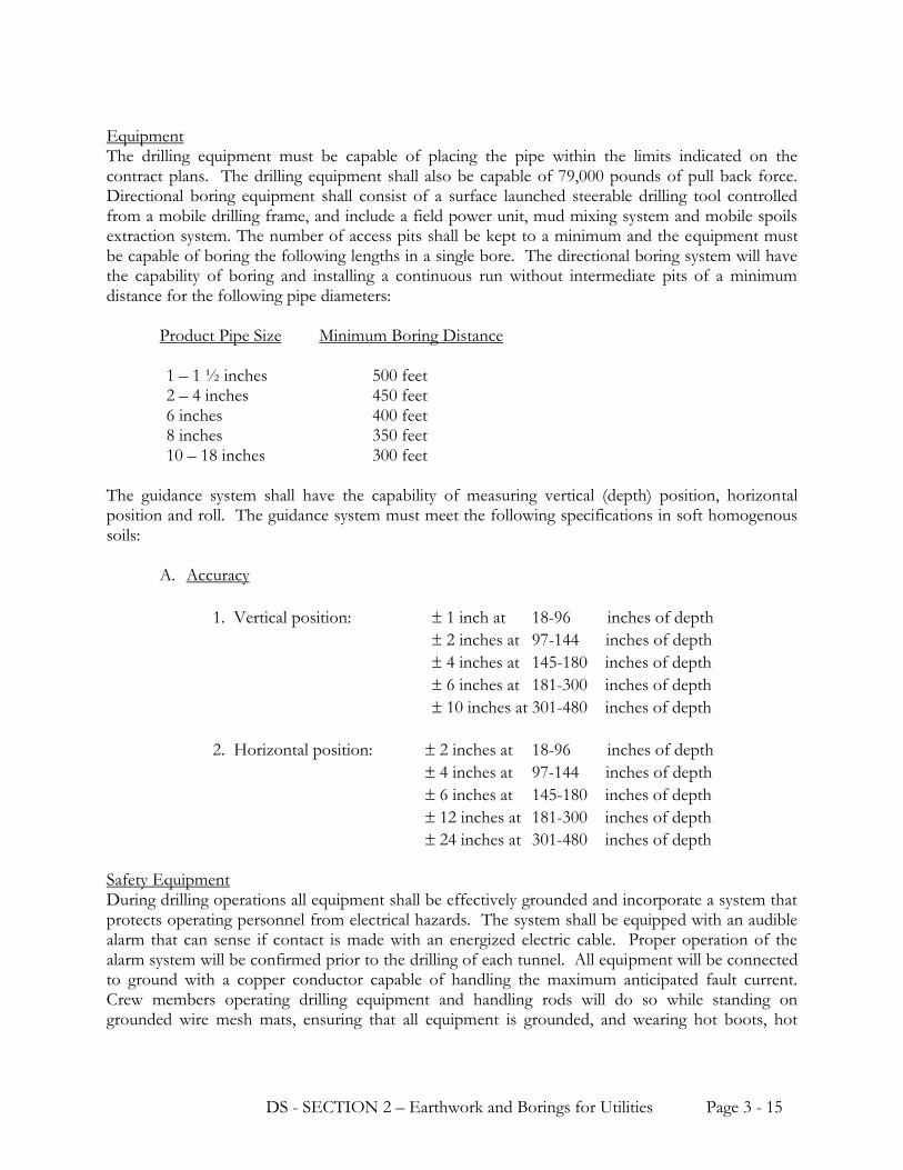
DS - SECTION 2 – Earthwork and Borings for Utilities Page 3 - 15
Equipment The drilling equipment must be capable of placing the pipe within the limits indicated on the contract plans. The drilling equipment shall also be capable of 79,000 pounds of pull back force. Directional boring equipment shall consist of a surface launched steerable drilling tool controlled from a mobile drilling frame, and include a field power unit, mud mixing system and mobile spoils extraction system. The number of access pits shall be kept to a minimum and the equipment must be capable of boring the following lengths in a single bore. The directional boring system will have the capability of boring and installing a continuous run without intermediate pits of a minimum distance for the following pipe diameters:
Product Pipe Size Minimum Boring Distance 1 – 1 ½ inches 500 feet 2 – 4 inches 450 feet 6 inches 400 feet 8 inches 350 feet 10 – 18 inches 300 feet
The guidance system shall have the capability of measuring vertical (depth) position, horizontal position and roll. The guidance system must meet the following specifications in soft homogenous soils: A. Accuracy
1. Vertical position: 1 inch at 18-96 inches of depth
2 inches at 97-144 inches of depth
4 inches at 145-180 inches of depth
6 inches at 181-300 inches of depth
10 inches at 301-480 inches of depth
2. Horizontal position: 2 inches at 18-96 inches of depth
4 inches at 97-144 inches of depth
6 inches at 145-180 inches of depth
12 inches at 181-300 inches of depth
24 inches at 301-480 inches of depth Safety Equipment During drilling operations all equipment shall be effectively grounded and incorporate a system that protects operating personnel from electrical hazards. The system shall be equipped with an audible alarm that can sense if contact is made with an energized electric cable. Proper operation of the alarm system will be confirmed prior to the drilling of each tunnel. All equipment will be connected to ground with a copper conductor capable of handling the maximum anticipated fault current. Crew members operating drilling equipment and handling rods will do so while standing on grounded wire mesh mats, ensuring that all equipment is grounded, and wearing hot boots, hot

DS - SECTION 2 – Earthwork and Borings for Utilities Page 3 - 16
gloves, safety glasses and hard hats. Crewmembers operating handheld locating equipment will wear hot boots. Pilot Hole Boring / Adjustments / Restarts The entry angle of the pilot hole and the boring process will maintain a curvature that does not exceed the allowable bending radii of the product pipe. The Contractor shall follow the pipeline alignment as shown on the Drawings, within the specifications stated. If adjustments are required, the Contractor shall notify ESD for approval prior to making the adjustments. Product Pipe Installation After the pilot hole is completed, the Contractor shall install a swivel to the reamer and commence pullback operations. Pre-reaming of the tunnel may be necessary and is at the option of the Contractor.
a. Reaming diameter will not exceed 1.5 times the diameter of the product pipe being installed. b. The product pipe being pulled into the tunnel will be protected and supported so that it
moves freely and is not damaged by stones and debris on the ground during installation. The drilling fluid should remain in the tunnel to ensure the stability of the tunnel, reduce drag on the pulled pipe, and provide backfill with the annulus of the pipe and tunnel.
b. Pullback forces will not exceed the allowable pulling forces for the product pipe.
c. The Contractor shall allow sufficient lengths of product pipe to extend past the termination
point to allow connections to the diffuser assembly. Pulled pipe will be allowed 24 hours of stabilization prior to making tie-ins. The length of extra product pipe will be at the Contractor’s discretion.
d. The contractor shall allow at a minimum of 20 linear feet of directional-drilled pipe on each
end of the installation. The additional pipe lengths shall be on a parallel plane with the existing grade at the point of connection to the Ductile Iron or PVC main.
Cleanup and Disposal of Drilling Fluid The Contractor shall maintain the work site in a neat and orderly condition throughout the period of work and after completing the work at each site, remove debris, surplus material and temporary structures erected by the Contractor. The site shall be restored to a condition equal to the existing condition prior to being disturbed. Disposal of excess drilling fluid and spoils will be the responsibility of the Contractor who must comply with all relevant regulations, right-of-way, work space and permit agreements. Excess drilling fluid and spoils will be disposed at an approved location. The Contractor is responsible for transporting all excess drilling fluid and spoils to the disposal site and paying any disposal costs. Excess drilling fluid and spoils will be transported in a manner that prevents accidental spillage onto roadways. Excess drilling fluid and spoils will not be discharged into sanitary or storm drain systems, ditches or waterways.
a. Drilling fluid returns (caused by fracturing of formations) at locations other than the entry
and exit points will be minimized. The Contractor will immediately clean up any drilling fluid that surfaces through fracturing. Clean up of excess drilling fluid shall be accomplished by the means mobile spoils removal equipment.

DS - SECTION 2 – Earthwork and Borings for Utilities Page 3 - 17
b. Mobile spoils removal equipment capable of quickly removing spoils from entry or exit pits
and areas with returns caused by fracturing will be present during drilling operations to fulfill the requirements of paragraphs b and c above. The Contractor shall not commence drilling operations without the presence of drilling fluid removal equipment. All excess drilling fluid shall be removed from the site(s).
c. The Contractor will be responsible for making provisions for a clean water supply for the mixing of drilling fluid.
d. The contractor shall contain all drilling fluids from the site until such time that the excess
fluid may be removed from the site by mobile spoils removal equipment. e. At no time shall the contractor allow excess drilling fluids to drain into water bodies such as
streams, rivers, lakes, wetlands etc.. As-Builts The Contractor shall provide to ESD a bore plan (boring log) to provide the as-built condition of the bore. This information shall include the pipe depth at intervals of 50 lf, which shall indicate the horizontal alignment with respect to a horizontal baseline. FINISH OPERATIONS Grading Finish to grades indicated within one-tenth of a foot. Provide sod or topsoil in areas to be seeded or sodded in accordance with requirements specified in Section 4, "SITEWORK FOR PIPELINES." Grade areas to drain water away from structures and to provide suitable surfaces for mowing machines. Grade existing grades that are to remain but have been disturbed by the Contractor's operations. Spreading Topsoil Clear areas to receive topsoil for the finished surface of materials that would interfere with planting and maintenance operations. Scarify subgrade to a depth of 2 inches. Do not place topsoil when the subgrade is frozen, extremely wet or dry, or in other conditions detrimental to seeding, planting, or grading Spread topsoil to a uniform depth of 4 inches over the designated areas.
Borrow Area Grade to drain properly. Maintain and restore borrow pits.
Disposition of Surplus Material Surplus or other soil material not required or suitable for filling, backfilling, or grading shall be disposed of by the contractor. Protection of Surfaces Protect newly graded areas from traffic, erosion, and settlements that may occur. Repair or reestablish damaged grades, elevations, or slopes.

DS - SECTION 2 – Earthwork and Borings for Utilities Page 3 - 18
Pavement Repair Repair pavement, curbs, and gutters as specified in Section 4, "SITEWORK FOR PIPELINES." Do not repair pavement until trench or pit has been backfilled and compacted as specified herein. Provide a temporary road surface of gravel crushed stone over backfilled portion until permanent pavement is repaired. Remove and dispose of temporary road surface material when permanent pavement is placed. As a minimum, maintain one-way traffic on roads and streets crossed by trenches. Fully open roads and streets to traffic within 14 days. FIELD QUALITY CONTROL Test backfill for moisture-density relations in accordance with ASTM D698 as specified herein. Perform density and moisture tests in randomly selected locations and in accordance with ASTM D 1556 as follows:
A. Backfill in Road Shoulders: One test per 2500 linear feet in each lift. B. Backfill in Pavement Cuts: One test per 250 linear feet in each lift.
-- END OF SECTION --