Bamboo Reinforced Concrete in Earthquake Resistant Housing Interim Report

This paper was published in the Proceedings, Pacific Conference on Earthquake Engineering, Wairakei, New Zealand, August 5 - 8, 1987, Vol. 1, pp. 315 - 326.
EARTHQUAKE RESISTANT DESIGN CRITERIA FOR REINFORCED CONCRETE INTERIOR BEAM-COLUMN JOINTS
Kazuhiro Kitayama, Shunsuke Otani and Hiroyuki Aoyama
University of Tokyo, JAPAN
SUMMARY A set of earthquake resistant design criteria are proposed for reinforced concrete interior beam-to-column connections taking into account the expected deformation limits of a building. Although the shear failure in the beam-column connection is associated with the change in the shear transfer mechanism caused by the bond deterioration of beam bars within the connection, it is not feasible to prevent the deterioration. Therefore, some bond deterioration should be permitted, the criteria of which were determined on the basis of nonlinear earthquake response analyses of buildings with good and poor hysteresis energy dissipation. At the same time, the input shear to a beam-column joint is restricted in proportion to concrete compressive strength. The role of the lateral reinforcement is considered to confine the connection rather than to resist shear.
INTRODUCTION A reinforced concrete (R/C) building in Japan has been designed for a large earthquake load, which normally results in wide columns. Hence, the shear stress in a beam-column connection and bond stress along the beam longitudinal reinforcement are kept low even in case of a large earthquake. The damage of beam-column sub-assemblages was scarcely observed in the past earthquakes. Therefore, the design of R/C beam-column joints has not been required in the Architectural Institute of Japan Standard for Structural Calculation of Reinforced Concrete Structures[1]. The rationalization of the design calculation, the use of higher strength materials might make it possible to construct new types of buildings with smaller column sections, especially by the adoption of an ultimate strength design procedure relying on the ductility. Then beam-column joints may be proven to be a weak point, and seismic design provisions may become necessary for R/C beam-column joints in Japan. This paper discusses the earthquake resistant design of an interior beam-column joint in a weak-beam strong-column plane frame structure.
PERFORMANCE REQUIREMENTS OF BEAM-COLUMN JOINTS A beam-column joint should not fail during a strong earthquake because a) the gravity load must be sustained in the joint, b) a large ductility and energy dissipation can not be expected in the joint, and c) a joint is difficult to repair after an earthquake. However, some damage should be tolerated if the damage does not cause ill effects on the overall behaviour of the structure. The design of a joint against the gravity load and flexure is automatically satisfied if the column reinforcement is continued through the joint. However, the shear in a joint can be significantly different from that in the column nor the beam, and the joint should be designed against a brittle shear failure although some shear cracking may be accepted. At the same time, the anchorage of beam bars should be properly maintained to develop the weak-beam strong-column earthquake resistance mechanism. The shear failure of a joint panel and significant slippage of beam bars within a joint should be prevented up to a usable limit of structural deformation, which this paper arbitrarily defines as a beam ductility of four or a

story drift angle of 1/50, whichever is smaller.
SHEAR MECHANISMS IN BEAM-COLUMN JOINT Actions on an interior joint from connecting beams and columns are shown in Fig. 1. Shear transfer mechanisms in a joint have been described by Paulay et al.[2] as shown in Figs. 2.a, and 2.b. These are called "main strut mechanism" and "sub-strut mechanism" in this paper. The main strut is formed along the main diagonal of the joint panel as the resultant of the horizontal and vertical compression stresses acting at the beam and column critical sections. Note that the main strut exists without regard to the bond situation of beam bars within the joint. The sub-strut mechanism is formed by diagonal compression stresses distributed uniformly within the panel region. The diagonal strut stresses must balance with the tensile stress in the vertical and horizontal reinforcement and the bond stresses acting along the beam and column exterior bars. There may be a third transfer mechanism (truss mechanism) as shown in Fig. 2.c. This is a truss mechanism formed by the lateral reinforcement, diagonal concrete struts and the column exterior reinforcement. If the bond is perfect along the beam reinforcement, the main strut mechanism carries a part of shear nearly
equal to the compression force, e.g., Cb1 in Fig. 1, and the sub-strut mechanism carries the part nearly equal to the beam tension force Tb2. Therefore, the contribution of the sub-strut mechanism to shear resistance is comparable with that of the main strut mechanism. Note that the sub-strut mechanism is possible only when a good bond stress transfer is maintained along the beam and column reinforcement. However, it is not feasible to maintain perfect bond along the beam reinforcement after beam flexural yielding, and the bond deterioration starts from the tension side of the beam reinforcement. Once the bond along the beam reinforcement deteriorates, the sub-strut mechanism starts to lose shear transfer ability, and gradually the effectiveness of the joint lateral reinforcement will be lost. The main strut mechanism carries the entire shear in the joint. The shear transfer mechanism in a beam-column joint changes with the bond deterioration along the beam reinforcement. Note that the tension force, not transferred to the joint concrete by the bond, of the beam reinforcement must be resisted by the concrete at the compression face of the joint, increasing the magnitude of compression stresses in the main strut. Because the strut concrete is weakened by the reversed cyclic loading and because the compressive strength is reduced by the increasing tensile strain perpendicular to the direction of the main
Fig. 1: Design Stresses in interior beam-column connection
Fig. 2: Shear transfer mechanisms in joint

strut, the shear capacity of the main strut decreases and eventually fails in shear compression. The principal role of the lateral reinforcement in this case is to confine the cracked joint core concrete. The truss mechanism may be effective at this stage. An index, called "beam bar bond index", is introduced in this paper to indicate the possibility of bond degradation along the beam reinforcement. The average bond stress bu over the column width for simultaneous yielding of the beam reinforcement in tension and compression on the two sides of the joint is expressed as follows,
2y b
bc
f duh
= (1)
where yf : yield strength of beam bars (MPa), bd : diameter of beam bars and ch : column width. If the bond
strength is assumed to vary with the square root of the concrete compressive strength 'cf in MPa, the feasibility of bond degradation may be expressed by a bond index BI, defined as
'
b
c
uBIf
= (2)
The index increases for higher beam bar strength, larger diameter of beam bars, narrower column width, and weaker concrete strength. The bond deterioration is more likely to occur for a higher index value.
JOINT MECHANISM AND TEST RESULTS Two series of half-scale plane interior beam-column sub-assemblages (called J- and C-series) were tested at the University of Tokyo (Refs. 4 and 8).
Table 1: Properties of specimens J1 and C1 Specimen J1 J3 C1 C2
(a) Beam (200x300 mm) Top Bars 8-D13 8-D13 12-D10 12-D10
pt(%) 1.88 1.88 1.59 1.59 Bot. Bars 4-D13 4-D13 6-D10 6-D10
pt(%) 0.94 0.94 0.79 0.79 fy (MPa) 409 409 326 326
(b) Column (300x300 mm) Total Bars 16-D13 16-D13 16-D13 16-D13
Axial stress (kgf/cm2) 20.0 20.0 20.0 20.0 fy (MPa) 409 409 430 430
(c) Connection Hoops@(mm) 2-D6@75 4-D6@25 2-D6@70 4-D6@45
pw(%) 0.27 1.27 0.27 0.90 Concrete strength (MPa) 26.2 24.5 26.1 26.1
BI index 1.69 1.75 1.02 1.02 / 'u cv f 0.25 0.31 0.22 0.22
Note: pt; tensile reinforcement ratio, pw; web reinforcement ratio, fy: yield stress of reinforcement, f’c: concrete strength, BI: defined in Eq. (2), and / 'u cv f : input shear stress normalized by f’c.
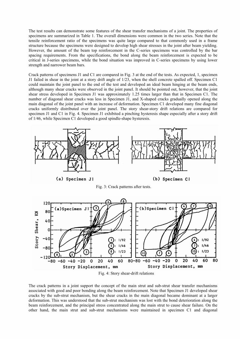
The test results can demonstrate some features of the shear transfer mechanisms of a joint. The properties of specimens are summarized in Table 1. The overall dimensions were common in the two series. Note that the tensile reinforcement ratio of the specimens was quite large compared to that commonly used in a frame structure because the specimens were designed to develop high shear stresses in the joint after beam yielding. However, the amount of the beam top reinforcement in the C-series specimens was controlled by the bar spacing requirements. From the specifications, the bond along the beam reinforcement is expected to be critical in J-series specimens, while the bond situation was improved in C-series specimens by using lower strength and narrower beam bars. Crack patterns of specimens J1 and C1 are compared in Fig. 3 at the end of the tests. As expected, 1, specimen J1 failed in shear in the joint at a story drift angle of 1/23, when the shell concrete spalled off. Specimen C1 could maintain the joint panel to the end of the test and developed an ideal beam hinging at the beam ends, although many shear cracks were observed in the joint panel. It should be pointed out, however, that the joint shear stress developed in Specimen J1 was approximately 1.25 times larger than that in Specimen C1. The number of diagonal shear cracks was less in Specimen J1, and X-shaped cracks gradually opened along the main diagonal of the joint panel with an increase of deformation. Specimen C1 developed many fine diagonal cracks uniformly distributed over the joint panel. The story shear-story drift relations are compared for specimen J1 and C1 in Fig. 4. Specimen J1 exhibited a pinching hysteresis shape especially after a story drift of 1/46, while Specimen C1 developed a good spindle-shape hysteresis.
The crack patterns in a joint support the concept of the main strut and sub-strut shear transfer mechanisms associated with good and poor bonding along the beam reinforcement. Note that Specimen J1 developed shear cracks by the sub-strut mechanism, but the shear cracks in the main diagonal became dominant at a larger deformation. This was understood that the sub-strut mechanism was lost with the bond deterioration along the beam reinforcement, and the principal stress concentrated along the main strut to cause shear failure. On the other hand, the main strut and sub-strut mechanisms were maintained in specimen C1 and diagonal
Fig. 3: Crack patterns after tests.
Fig. 4: Story shear-drift relations

compression stresses distributed uniformly in the panel concrete. The amount of lateral reinforcement was increased in Specimen J3 and C2 from the corresponding Specimens J1 and C1, respectively, maintaining the remaining parameters of the specimens (Table 1). Strains in joint lateral reinforcement are compared in Fig. 5. In Specimens J1 and J2 with relatively poor bond situation, the strains were comparable up to a story drift angle of 1/46, where a pinching was observed, although the lateral reinforcement ratio was increased from 0.27 % to 1.27 %. Whereas, larger strains were observed in Specimen C1 than in Specimen C2 by changing a lateral reinforcement ratio from 0.27 % to 0.90 %.
The role of the lateral reinforcement in the two series appears different depending on the degree of the bond deterioration along the beam reinforcement. Note that the strain in Specimen J3 continued to increase after the bond deterioration, the phenomenon of which cannot be explained by the loss of the sub-strut mechanism. The truss mechanism in Fig. 2 must have partially contributed to the joint shear resistance, and also the lateral reinforcement acted to confine the cracked core concrete. An increasing amount of lateral reinforcement was observed to reduce the shear deformation and crack width in the joint panel, but the difference appeared at a story drift angle greater than 1/46 in C-series tests.
EFFECT OF BOND DETERIORATION ON RESPONSE It was considered that the bond deterioration of beam bars within a joint is not desirable for the reasons as follows; (1) Pinching appears in the hysteresis shape reducing the energy dissipating ability of beams, (2) The compressive stresses increase at the beam critical section, and increase the diagonal compression stress amplitude, causing shear distress in a joint after beam yielding, and (3) The region of beam reinforcement under tension increases within the connection, increasing the beam deformation due to the additional rotation at the critical section caused by beam bar slip within a joint. It is important to note that the bond deterioration and shear resistance are closely related. The influence of the energy dissipation capability at the beam ends on earthquake responses is studied to discuss the permissibility of the beam bar slip within a joint. The earthquake response analyses were carried out by a computer program DANDY[7]. Each member was represented by a one-component model, in which an inelastic rotational spring was placed at member ends. A beam-column joint was assumed to be rigid. The hysteresis models placed at beam ends were selected to simulate the pinching behavior caused by the bond deterioration along the beam reinforcement (Takeda-Slip hysteresis model). Takeda model was used to simulate a good bond situation with a spindle-shape hysteresis (Fig. 6). The skeleton curves of both models were common, but the values of parameters for the hysteresis shape were chosen from J- and C-series tests to study the effect of decrease in hysteretic area on the response; an equivalent viscous damping ratio heq, ratio of the dissipated energy within half a cycle to 2 times the strain energy at peak of an equivalent linearly elastic system, was 0.25 for Takeda model and 0.15 for Takeda-Slip
Fig. 5: Strains in joint lateral reinforcement
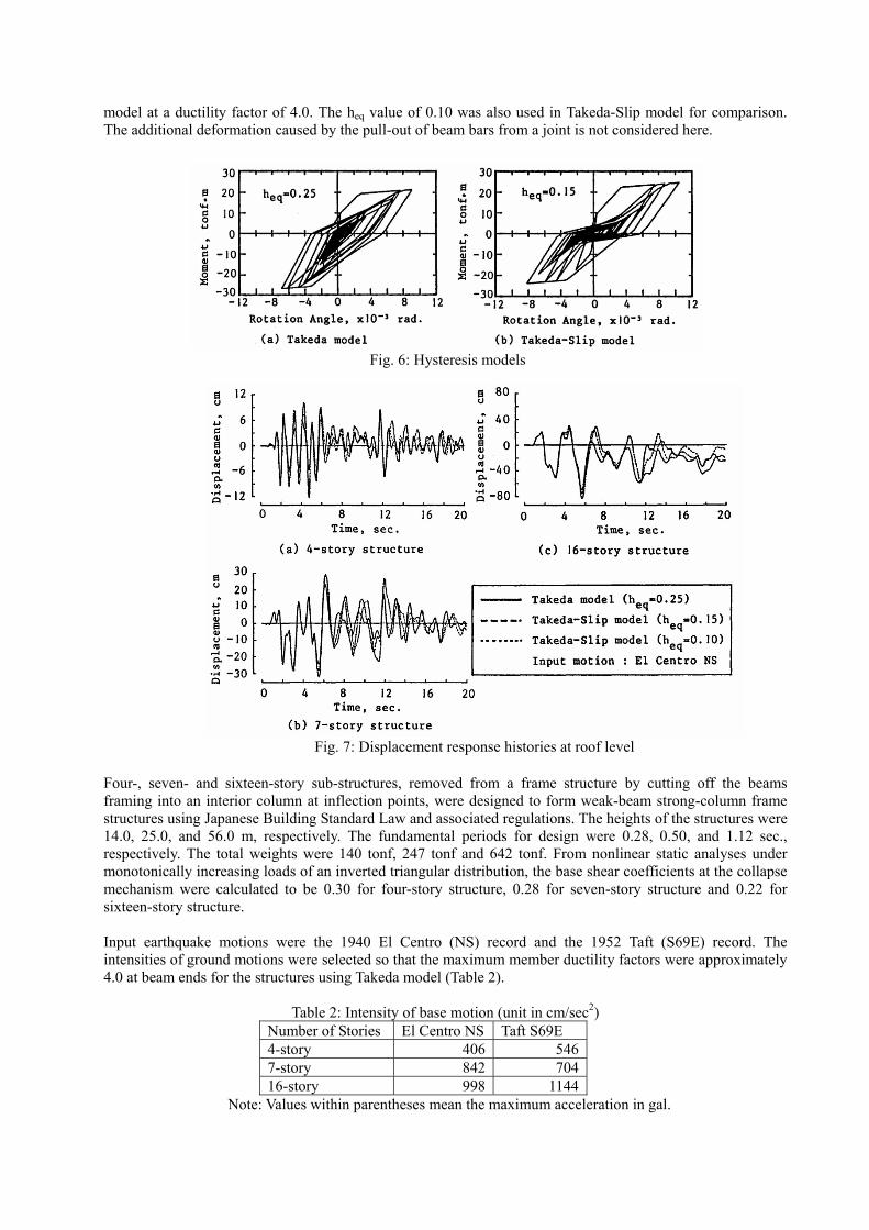
model at a ductility factor of 4.0. The heq value of 0.10 was also used in Takeda-Slip model for comparison. The additional deformation caused by the pull-out of beam bars from a joint is not considered here.
Four-, seven- and sixteen-story sub-structures, removed from a frame structure by cutting off the beams framing into an interior column at inflection points, were designed to form weak-beam strong-column frame structures using Japanese Building Standard Law and associated regulations. The heights of the structures were 14.0, 25.0, and 56.0 m, respectively. The fundamental periods for design were 0.28, 0.50, and 1.12 sec., respectively. The total weights were 140 tonf, 247 tonf and 642 tonf. From nonlinear static analyses under monotonically increasing loads of an inverted triangular distribution, the base shear coefficients at the collapse mechanism were calculated to be 0.30 for four-story structure, 0.28 for seven-story structure and 0.22 for sixteen-story structure. Input earthquake motions were the 1940 El Centro (NS) record and the 1952 Taft (S69E) record. The intensities of ground motions were selected so that the maximum member ductility factors were approximately 4.0 at beam ends for the structures using Takeda model (Table 2).
Table 2: Intensity of base motion (unit in cm/sec2) Number of Stories El Centro NS Taft S69E 4-story 406 5467-story 842 70416-story 998 1144
Note: Values within parentheses mean the maximum acceleration in gal.
Fig. 6: Hysteresis models
Fig. 7: Displacement response histories at roof level

Fig. 8: Attained ductility factors at beam ends

Time-histories of displacement responses at the roof level are shown in Fig. 7 and attained ductility factors at beam ends are shown in Fig. 8. The distribution of beam-end ductility demands of a structure with Takeda model is similar to that with Takeda-Slip model (heq=0.15). The change in the heq value of Takeda-Slip model from 0.15 to 0.10 did not affect the ductility demand at beam ends. Although the displacement response waveforms of the structures with Takeda-Slip model deviated from those of the structure with Takeda model, the attained maximum response displacements were comparable for the three structures. From the results of earthquake response analyses, the effect of hysteresis energy dissipating capacity on the response was found relatively small for a range of equivalent viscous damping ratio from 0.10 to 0.25 at ductility factor of 4.0. Therefore, some bond deterioration of beam bars within a joint may be tolerable.
LIMITATION OF BEAM BAR BOND INDEX The beam bar bond index and the equivalent viscous damping ratio heq are compared for the plane beam-column sub-assemblages tested at the University of Tokyo (S-, J- and C-series tests [Refs. 8, 3, 4]) at a story drift angle of 1/92 rad and 1/46 rad in Fig. 9. The solid line was derived from the least squares method to fit the data. The broken lines in Fig. 9(b) show the heq values used in the nonlinear analyses, i.e., heq= 0.25, 0.15 and 0.10. In Fig. 9(a), the specimens with open symbols developed beam yielding at the story drift angle of 1/92 rad, while the specimens with solid symbols did not. The heq values do not show a correlation with the beam bar bond index values at the story drift angle of 1/92 rad. However, the heq values tend to decrease with an increasing beam bar bond index value at the story drift angle of 1/46 rad (Fig. 9(b)). If an allowable deformation level of R/C frame structures is taken to be a story drift angle of 1/50 rad, the beam bar bond index should satisfy Eq.(3) to ensure the equivalent viscous damping ratio of 0.10, as indicated in the earthquake response analyses.
1.6'
b
c
uf
≤ (3)
where unit of both bu and 'cf are in MPa. Substituting bu in Eq.(1) into Eq.(3), the following expression is obtained.
3.2 '
yc
b c
fhd f
≥ (4)
This recommendation with regard to the ratio of the column width to the beam bar diameter is compared with both the NZS 3101:1982 code and the ACI-ASCE 352 recommendation [9] in Fig. 10. The /c bh d ratio is moderated in this recommendation in comparison with the NZS 3101:1982 code provision.
LIMITATION OF INPUT SHEAR INTO A JOINT After some bond deterioration along the beam reinforcement in a joint, the shear stress within a panel region is carried dominantly by the main strut mechanism. The shear compression failure in the main strut mechanism may be retarded by restricting the level of shear stress. The joint lateral reinforcement ratio is compared with the value vu/ fc' for plane beam-column sub-assemblage test specimens, reported in Refs. [3, 4, 8, 10-13], in Fig. 11, in which vu is the maximum joint shear stress observed in the test. The effective joint area to resist shear is defined as the column depth multiplied by the average of the beam and column widths. The lateral reinforcement ratio was defined as the total cross-sectional area of lateral reinforcement within a joint divided by the column width and the distance ( = 7/8 d) between resultant tension and compression forces at the beam critical section. From the figure, the joint shear stress vu must be limited as given in Eq. (5) to prevent shear failure after beam flexural yielding;

0.25'u
c
vf
< (5)
The shear failure in a joint panel occurred in spite of the amount of lateral reinforcement if / 'u cv f is greater than 0.25. But shear failure after beam yielding occurred at a story drift angle of greater than 1/25 rad. When the allowable drift is assumed to be 1/50 rad, the limitation of / 'u cv f may be limited by 0.25. If an input shear stress vu exceeds 0.25 'cf , the joint failed in shear irrespective of the amount of lateral
Fig. 9: Equivalent viscous damping ratio beam bar bond index relations
Fig. 10: Required column width to beam bar diameter

reinforcement within a joint. On the other hand, the lateral reinforcement ratio of 0.27 % is sufficient when the input shear stress vu is less than 0.25 'cf . From these test results, 0.30 % is recommended as the required minimum lateral reinforcement ratio of a joint. The lateral reinforcement within a joint is expected to confine the panel concrete.
CONCLUDING REMARKS The change of the joint shear transfer mechanism caused by the bond deterioration along beam reinforcement was pointed out. The ratio of the column width to the beam bar diameter must be limited as function of the strength of beam bars and concrete strength. The design shear stress should be limited to prevent shear compression failure after the bond deterioration along the beam reinforcement. A minimum amount of lateral reinforcement must be placed within a joint to confine the concrete of the main strut.
REFERENCES [1] Architectural Institute of Japan, "AIJ Standard for Structural Calculation of Reinforced Concrete Structures (in Japanese)", revised in 1982. [2] Paulay, T., R. Park and M. J. N. Priestley, "Reinforced Concrete Beam-Column Joints Under Seismic Actions", ACI Journal, November 1978, pp. 585 - 593. [3] Otani, S., Y. Kobayashi, M. Tamari and H. Aoyama, "Shear Resistance of Reinforced Concrete Beam-Column Connections in Weak-Beam Frames (in Japanese)", Reports, Annual Meeting, Architectural Institute of Japan, October 1984, pp. 1891 - 1892. [4] Kitayama, K., K. Kurusu, S. Otani and H. Aoyama, "Behavior of Beam-Column Connections with Improved Beam Reinforcement Bond", Transactions of The Japan Concrete Institute Vol. 7, 1985, pp. 551 - 558. [5] American Concrete Institute, "Building Code Requirements for Reinforced Concrete (ACI 318-83)", Detroit, revised in 1983. [6] Standard Association of New Zealand, "New Zealand Standard Code of Practice for the Design of Concrete Structures", NZS 3101, 1982. [7] Kabeyasawa, T., S. Otani and H. Aoyama, "Nonlinear Earthquake Response Analyses of R/C Wall-Frame Structures", Transactions of The Japan Concrete Institute Vol. 5, 1983, pp. 277-284. [8] Kobayashi, Y. and S. Otani, "A Study on Beam Bar Bond in Reinforced Concrete Beam-Column Joints Part 1 (in Japanese)", Reports, Annual Meeting, Architectural Institute of Japan, September 1983, pp. 1819 - 1820.
Fig. 11: Joint lateral reinforcement ratio - normalized input shear stress relation

[9] ACI-ASCE Committee 352, "Recommendations for Design of Beam-Column Joints in Monolithic Reinforced Concrete Structures", ACI Journal, May-June 1985, pp. 266 - 283. [10] Noguchi, H. and H. Terasaki, "Experimental Study on RC Beam-Column Joints Subjected to Seismic Stresses (in Japanese)", Summaries of Technical Papers of Annual Meeting Structures II, Architectural Institute of Japan, October 1985, pp. 291 - 292. [11] Tada, T. and T. Takeda, "Research on Reinforcement of Beam-Column Joint Panel for Seismic Resistant Reinforced Concrete Frame part 1 (in Japanese)", Journal of Structural and Construction Engineering No. 352, Architectural Institute of Japan, June 1985, pp. 68 - 78. [12] Hamada, D., T. Kamimura and S. Hayashi, "Experimental Study on Beam-Column Joints in Reinforced Concrete Structures part 1 (in Japanese)", Reports, Annual Meeting, Architectural Institute of Japan, September 1978, pp. 1673 - 1674. [13] Meinheit, D. F. and J. O. Jirsa, "The Shear Strength of Reinforced Concrete Beam-Column Joints", CESRL Report No. 77-1, The University of Texas at Austin, January 1977.