Early Phrygian Citadel Gate 2006 Treatment Report
166
Early Phrygian Citadel Gate 2006 Treatment Report As part of the Architectural Site Conservation at Gordion, Turkey Entrance of the Citadel Gate (Wong, 2006) Prepared by: Kelly H. Wong Project Director: Frank G. Matero Professor of Architecture Graduate Program in Historic Preservation School of Design University of Pennsylvania Prepared for: The Gordion Excavation Project, The Samuel H. Kress Foundation, and The Keepers Preservation Education Fund October 2006
Transcript of Early Phrygian Citadel Gate 2006 Treatment Report

Early Phrygian Citadel Gate 2006 Treatment Report
As part of the Architectural Site Conservation
at Gordion, Turkey
Entrance of the Citadel Gate (Wong, 2006)
Prepared by: Kelly H. Wong
Project Director: Frank G. Matero
Professor of Architecture Graduate Program in Historic Preservation
School of Design University of Pennsylvania
Prepared for:The Gordion Excavation Project,
The Samuel H. Kress Foundation, and The Keepers Preservation Education Fund
October 2006

Gordion Excavation Project Architectural Conservation University of Pennsylvania Summer 2006
University of Pennsylvania Citadel Gate Field Report i
TABLE OF CONTENTS
I. OBJECTIVES………………………………………………………………………………. 1
II. SITE DESCRIPTION………………………………………………………………………. 2
A. Architectural Description……………………………………………………………... 2
B. Excavation/Conservation History……………………………………………………. 3
III. METHODOLOGY………………………………………………………………………….. 8
A. Conditions Survey. …………………………………………………………………… 8
B. Grout Injection for Stabilization ……………………………………………………. 10
C. Micro Grout Injection for Crack Repairs…………………………………………... 13
D. Removal and Storage of Large Masonry Spalls …………………………………. 16
E. Crack Gauges for Monitoring Wall Deformation………………………………….. 17
F. Setting Project Parameters…………………………………………………………..18
IV. OBSERVATIONS………………………………………………………………………… 19
A. Current Conditions …………………………………………………………….……. 19
1. North Court ………………………………………………………………………. 20
a. Roof/Concrete Capping. …………………………………………………. 20
b. Exterior Elevations………………………………………………………… 21
c. Interior Elevations…………………………………………………………. 26
2. South Court ………………………………………………………………………. 29
a. Roof/Concrete Capping. …………………………………………………. 29
b. Exterior Elevations………………………………………………………… 30
V. TREATMENT PROGRAM………………………………………………………………. 36
A. Conditions Survey. ………………………………………………………………….. 36
B. Grout Injection for Stabilization ……………………………………………………. 38
C. Micro Grout Injection for Crack Repairs…………………………………………... 40
D. Removal and Storage of Large Masonry Spalls …………………………………. 42
E. Crack Gauges for Monitoring Wall Deformation………………………………….. 43
F. Setting Project Parameters…………………………………………………………. 44

Gordion Excavation Project Architectural Conservation University of Pennsylvania Summer 2006
University of Pennsylvania Citadel Gate Field Report ii
VI. CONCLUSION…………………………………………………………………………… 45
VII. RECOMMENDATIONS…………………………………………………………………. 46
A. Immediate (0-1 year)………………………………………………………………… 46
B. Short-term (2-5 years)………………………………………………………………. 47
C. Long-term (6-10 years)………………………………………….………………….. 48
VIII. BIBLIOGRAPHY………………………………………………………………………… 49
APPENDICES…………………………………………………………………………………. 52
Appendix A. Conditions Survey……………………………………………………………… 53
Appendix B. Grout Injection………………………………………………………………….. 75
Appendix C. Micro-grout Injection…………………………………………………………… 84
Appendix D. Masonry Spalls removed and stored………………………………………… 89
Appendix E. Materials Specifications……………………………………………………….. 92
Appendix F. Samples collected for future testing………………………………………….. 98
Appendix G. Citadel Gate Chronology ……………………………………………………. 100
Appendix H. Comparison Photos (Historic vs. Current)…………………………………. 104
Appendix I. Interviews / Correspondences………………………………………………. 116
Appendix J. Field Notes…………………………………………………………………….. 128

Gordion Excavation Project Architectural Conservation University of Pennsylvania Summer 2006
University of Pennsylvania Citadel Gate Field Report 1
I. OBJECTIVES
The archaeological site of Gordion (Turkey) offers the world a glimpse of the Iron Age through a royal center comprised of impressive Megara buildings, a grand Terrace Building Complex, and the magnificent Citadel Gate complex, currently the most intact structure found at the Citadel Mound. Although Gordion is an archaeological site of unparalleled significance, the existing architectural features on site have been exposed to natural weathering for over 50 years and are currently in a poor state of deterioration.The monumental Citadel Gate is particularly vulnerable to effects of periodic seismic activity in the region.
A five-year architectural site conservation program established in 2006 by the University of Pennsylvania Graduate Program in Historic Preservation included the conservation of the Early Phrygian Citadel Gate. As part of this program, in summer 2006 the main objectives defined for the conservation of the Citadel Gate complex included:
� Conditions survey: Recording, surveying, and the analysis of the current conditions of the Citadel Gate complex;
� Grout injection: Continuation of the injection grouting program for stabilizing the South Court;
� Micro grout injection: Repairing masonry cracks using micro grout injection at the East and Northeast elevation of the South Court;
� Removal and storage of masonry spalls: Removal of masonry spalls from the South Court Northwest elevation and storage at the Excavation House for future reattachment by mechanical pinning;
� Crack gauges: Installation of crack gauges to monitor movement at the Northeast and West return elevations of the South Court; and
� Setting project parameters: Prompting a discussion regarding the importance of establishing project parameters for the stabilization of the Citadel Gate complex based on current and future goals and project budget.

Gordion Excavation Project Architectural Conservation University of Pennsylvania Summer 2006
University of Pennsylvania Citadel Gate Field Report 2
II. SITE DESCRIPTION
Constructed: ca. 875 BC Excavated: 1953-1955
A. Architectural Description
The Early Phrygian Citadel gate complex is composed of two structures (North Court and South Court buildings) flanking a central ramp which once led to a gate house(Fig. 1). The construction of a large drain (during the Terrace Building campaign) replaced the gate house immediately before the great fire in 800BC. The complex served as the main entrance to the Old Citadel on the southeastern edge of the Citadel Mound for only a short period between 875 and 850 BC before the construction of the new Terrace Gateway. The exterior east walls of the two courts align with the Old Citadel fortification walls. Its exterior walls flanking the entrance on the east and along the central ramp are battered inward approximately 5 cm for every 1 meter in height [AJA (66) 168].
Figure 1. Old Citadel Plan showing the Early Phrygian Gate complex (Alblinger 2002).

Gordion Excavation Project Architectural Conservation University of Pennsylvania Summer 2006
University of Pennsylvania Citadel Gate Field Report 3
The gate complex is a dried laid structure of roughly-coursed ashlar limestone with small chinking stones at its exterior with a rubble masonry core (Figs. 2 & 3). The structure’s multiple-leaf wall construction has interlocking masonry units only at wall intersections (such as the returns along the central ramp). When excavated, the entire complex was covered with coat of mud-plaster (clay stucco) and appeared to have been whitewashed [AJA 60 (1956) 257].
B. Excavation/Conservation History
The limestone masonry walls were found largely intact when excavated between 1953 and 1955 [AJA 59 (1955) 11]. Comparison of current photos with historic excavation photos and drawings, it is clear that portions of both the North and South Court walls were reconstructed after excavation to reestablish visual integration. For example, a historic drawing Plan1955-31 shows only the bottom third of the North Court southwest elevation when first excavated in comparison to the fully reconstructed elevation seen today in Photo Gordion06.Gate.NC.Reconstruction1_Rizzi (Figs. 4 & 5).
Young cleared nearly the entire Persian [later Middle Phrygian] Gate (in a poor state of preservation when excavated) [AJA 60 (1956) 252-253] to reveal the Early Phrygian gate below. Fortunately, the North and South Courts and the central ramp of the earlier Phrygian gate was found filled with rubble masonry, wooden timbers, and a layer clay which contributed to its excellent state of preservation. The fill within the North Court building was removed during excavations and in 1955 the western portion of the southwest wall was reconstructed reusing the masonry of a later Persian [Middle Phrygian] dam wall [AJA 60 (1956) 258].
Figures 2 & 3. (Left) View of Gate entrance from East (Wong 2006). (Right) shows the dry laid masonry construction at the Southwest wall of the North Court building (Matero 2005).

Gordion Excavation Project Architectural Conservation University of Pennsylvania Summer 2006
University of Pennsylvania Citadel Gate Field Report 4
In 1956, only one year after excavation, a concrete cap was installed on top of the gate excluding a large portion of the south side to protect the structure from water intrusion [Rogers 1989, 11]. A temporary cap composed of clay (taken from another part the site) was placed on the uncapped section of the gate in 1987 to protect the structure [Rogers 1989, 16]. However, according to Goodman even after the 1956 cap was replaced by an improved concrete capping/drainage system in 1988, exposure to weather and seismic activity accelerated the deterioration and detachment of the load-bearing veneer stones at the South Court [Goodman 2005, 219]. The new 1988 capping was also constructed of concrete but installed in sections (Figs. 6 & 7). In 1996, cracks found mainly between the sections of the capping at the North Court were repaired with a locally available silicone sealant (Silikon Mastik 29-11-95 by Henkel Kalitesi �le) by architectural conservator Evan Kopelson [Kopelson field notebook 1996)].
Figure 5. The North Court Southwest wall after reconstruction in summer 2006 (Rizzi 2006).
Figure 4. Plan1955-31 – a rendering of the North Court Southwest elevation in 1955 after excavation (Gordion Archives 1955).
Figure 6. 1988 concrete capping at the North Court (Wong 2006).
Figure 7. 1988 concrete capping at the South Court (Wong 2006).

Gordion Excavation Project Architectural Conservation University of Pennsylvania Summer 2006
University of Pennsylvania Citadel Gate Field Report 5
Conservation efforts at the Citadel gate have focused primarily on the unstable sections of the South Court. By 1987 after 32 years of exposure and a failing concrete cap (a fractured cap, a bulge at the upper level of the northeast elevation became readily visible. This condition led to a series of monitoring systems beginning with glass tell-tales installed in 1987 to monitor movement at the bulge [Rogers 1989, 15 and Gordion Notebook 173] and then a system in 1989 using a series of nails set into critical points of the wall which were periodically checked with a laser theodolite by Bill Remsen [Goodman 1999, 5]. This method was again used in 2006 to construct a simple digital model of the Gate complex as well as the profiles of the bulges found on the Northeast exterior elevation at the South Court and the East interior elevation at the North Court(Fig. 8). In 1999, structural engineer Conor Power simplified the 1989 monitoring system by using plumblines to observe movement along the bulge (Fig. 9) [Goodman 2005, 219]. Immediately following the 7.8M Izmit earthquake on August 16, 1999, Power considered the structure dangerously unstable with a high probability of collapse [Goodman 1999, 6].
Figure 8. Using a laser theodolite to create a 3D frame of the Gate and profile of the bulges found at the complex (Wong 2006).
Figure 9. Simplified system of plumblines used to monitor movement along the bulge at the South Court Northeast elevation (Goodman 1999).

Gordion Excavation Project Architectural Conservation University of Pennsylvania Summer 2006
University of Pennsylvania Citadel Gate Field Report 6
In response to the instability of the South Court, stabilization by grout injection was first recommended in 1989 by architectural conservator Bernard Fielden to reestablish the bond between the veneer and core [Goodman 1999, 5]. After structural scaffolding was erected in 2001, a formal grout injection program led by site conservation director Mark Goodman was established in 2002. By the end of the 2006 season, only portions of the South Court have been grouted including: the bottom portion of the east elevation (as part of the pilot program in 2001), the bottom third of both the northeast elevation and the west return (2002-2004), and the bottom half of the northwest elevation (2002-2006). Although bulges are visible at the North Court interior (north and east) elevations, grout injection has yet to be introduced in this area.
As part of the 2006 Conservation Program, a five-year plan developed by the University of Pennsylvania in collaboration with the Middle Eastern Technical University (Ankara, Turkey), activities initiated in summer 2006 included the documentation, recording, and analysis of the Gate complex through a Conditions Survey (Fig. 12), continuation of injection grouting for stabilizing the South Court building, repairs of cracks by micro grout injection (Fig. 13), removal and storage of masonry spalls for future reattachment by mechanical pinning, installation of experimental crack gauges for monitoring structural movement, and the reconstruction of a portion of the Southwest elevation at the North Court (northwest wall of Passage). Additionally, a discussion regarding the importance of establishing project parameters for the stabilization of the Citadel Gate complex based on current and future goals was also prompted.
Figures 10 & 11. (Left) Grout injection in 2001 of the East elevation of the South Court (Goodman 2001). (Right) Continuation of the grout injection program in 2006 at the Northwest elevation of the South Court (Wong 2006).

Gordion Excavation Project Architectural Conservation University of Pennsylvania Summer 2006
University of Pennsylvania Citadel Gate Field Report 7
Figure 12. Graduate student intern Gülsün Özkan from Middle Eastern Technical University conducting the Conditions Survey at the Citadel Gate (Wong 2006).
Figure 13. Current site conservation director Frank Matero showing the micro grout injection technique to repair masonry cracks (Cleary 2006).

Gordion Excavation Project Architectural Conservation University of Pennsylvania Summer 2006
University of Pennsylvania Citadel Gate Field Report 8
III. METHODOLOGY
The following section includes the methodology for the following six conservation tasks initiated in summer 2006:
� Conditions survey of the Citadel Gate complex; � Grout injection for stabilization at the Northwest elevation of the South Court; � Micro grout injection at the Northeast and East elevations; � Removal and storage of loose masonry spalls; � Crack gauges installed to monitor wall deformations at the South Court; and � Setting project parameters for future stabilization of the Citadel Gate complex.
A. Conditions Survey
An on-site conditions survey documenting the current conditions of the Citadel Gate complex was completed in order to better understand the different mechanisms causing deterioration. From this survey, specific conservation measures can be proposed to appropriately treat the structure. Survey included only excavated architectural fabric from the Early Phrygian period (9th century BC). The Citadel Gate complex includes the North Court and South Court structures. Each elevation of the two Courts was digitally photographed and rectified in Adobe Photoshop for use as baseline images for recording conditions. The photo elevations are representational. If measured drawings are required, large format photography can be undertaken in order to provide scale and accuracy.
Procedure
Graphic documentation is a useful technique for monitoring conditions of historic structures especially excavated fabric exposed to natural weathering such as the Citadel Gate complex.
1. Conditions Survey Terminology Descriptive terminology of the conditions and structure was established for the on-site survey and its digitized format. A conditions legend including seven conditions found at the Citadel Gate was used for the survey (see Appendix A. Conditions Survey):
1. Bulges: large area deformation; 2. Cracks: both small and large found on surfaces, as well as thru masonry units; 3. Split-face: characteristic mainly found at bed-faced masonry units; 4. Spalls: where portions of stone faces were missing; 5. Opened joints: large areas found between masonry units; 6. Missing chinking stones: where stones are displaced or missing; and 7. Erosion: of masonry caused by water damage or poor quality masonry material.

Gordion Excavation Project Architectural Conservation University of Pennsylvania Summer 2006
University of Pennsylvania Citadel Gate Field Report 9
2. Photo Documentation & Montage � Document areas (elevations) to be surveyed using digital photography (jpeg
format);� Photo-rectify and montage individual photographs into full elevations in
Photoshop (Fig. 14); � Print out elevations and draw reference point; and � Insert elevation into clear acetate/nylon protector sheet and draw reference point
and corners of image – this is the survey form.
3. Survey � Bring the survey form and the conditions legend to the site to conduct
assessment; and � Record conditions on the survey form using various colored permanent markers
(Fig. 15).
4. Post-Survey Digital Transfer � Once the survey of an entire elevation is complete, return survey forms to the
Gordion Excavation House for digitizing; � Remove printed elevation from the protector sheet; � Scan the protector sheet with the recorded conditions and save as a digital
image (jpeg). This digital image can later be imported in AutoCAD as an overlay to enable tracing (the conditions) once elevations are drawn or imported as digital images themselves; and
� Return printed elevations to protector sheets and store the survey forms in the Gate Dossier Folder at the Gordion Excavation House.
Figure 14. Example of a photo-rectified and montaged elevation used for the Conditions Survey (Wong 2006).
Figure 15. Graduate student intern Gülsün Özkan recording conditions at the Citadel Gate (Wong 2006).

Gordion Excavation Project Architectural Conservation University of Pennsylvania Summer 2006
University of Pennsylvania Citadel Gate Field Report 10
B. Grout Injection for Stabilization
Injection grouting at the upper portions of the northwest elevation of the South Court by a Turkish team of three masons and five workmen was a continuation of a grouting program established in 2001 to stabilize the Citadel Gate. The objective for summer 2006 was to complete the rest this elevation. Injection grouting of this area was completed between July 1, 2006 and August 2, 2006.
A structural stabilization program using a method known as “gravity grouting” began in 2001 led by Mark Goodman, site conservation director from 1999-2004. Gravity grouting is the use of gravity to develop injection pressure by raising a grout reservoir above the injection point. This method was selected as a low-tech alternative to a more complex and expensive pressure pot or a grout pump prone to blockages and mechanical breakdowns [Goodman 2003, 4]. The injection grouting of the Citadel Gate procedure was completed between July 5 and August 2, 2006.
Procedure
1. Identification � The upper area of the northwestern elevation of the South Court was selected for
the grout injection program for summer 2006. This is above an area previously grouted;
� Identify the grout lift area. [Grout injection was limited to the height of one grout lift (usually the three stone courses or 50-70 cm) at any one time to avoid destabilization of the wall.]; and
� Identify areas where grout pipes can be inserted as the “grout points.”
2. Recording & Documentation � Document areas to be grouted using digital photography (jpeg format); � Photo-rectify and montage photographs into a full elevation in Photoshop; � Print out the photo elevation and record grout points. [The photo elevation is also
used as a record of the original locations of the chinking stones to be restored after their temporary removal during the grouting process.]; and
� Record the location, date, and amount of grout injected into the structure at each grout point in a notebook. Use the photo elevation to supplement this data.
3. Mixtures (by volume)
The following table shows the formulations used for the grout, mud slurry, and pointing mortar. The grout mixture is used for consolidating the rubble core masonry voids. The pointing mortar is used for restoring the chinking stones. And the mud slurry is used to coat the masonry wall in the areas of and below the intended grout injection as a sacrificial layer to prevent adhesion of spilled grout. See section IV. Treatment Program for specifications of the materials used for the grout mixture. Also see Appendix E. Materials Specifications for further details.

Gordion Excavation Project Architectural Conservation University of Pennsylvania Summer 2006
University of Pennsylvania Citadel Gate Field Report 11
Grout & Mortar Mixtures (by volume)
Mixture HHL Lime Putty Sand Brick Dust Grout 3½ ½ 16 2 Pointing Mortar - 1 1½ - 2 1/3 Mud Slurry (No specified formulation – only a mixture of lsoil and water)
HHL – Hydrated Hydraulic Lime Lime Putty – Hydrated Lime
4. Dry/Wet Cleaning Dry Cleaning
� Remove small stones and loose dirt from between ashlar units to maximize penetration and adhesion of the grout mortar, as well as preventing potential blockages in the masonry core; and
� Temporarily remove original stone chinking to provide room for injection points.
Wet Cleaning � Flush out voids with water to fully remove loose debris and improve adhesion
between the masonry surface and injection grout. Wet cleaning can also prevent drying out the grout mixture caused by dry masonry absorbing water after injection.
5. Lift Area Preparation � Wash the entire lift area with the mud slurry to protect the original limestone
surface from grout overspill during grouting; � Insert and mortar in place standard PVC pipes into existing masonry joints and
cracks in the wall, designated as the grout injection points; � Clamp a 35 cm cut length of fire hose “coupler” to the embedded pipes; � Loosely fit a second clamp over the fire hose coupler used for connecting the
grouting nozzle to the pipe. The grouting nozzle extends from the grout bucket.; and
� Temporarily stuff rags saturated in mud slurry into all remaining openings in the grout lift to prevent grout spilling.
6. Grout Preparation� Mix grout in the motorized mortar mixer for 15 minutes [approximately 60-70
liters per mix] (Fig. 16); � Pour the grout mixture into the 70 liter grout bucket situated on the “grout
wagon.” A small railroad was constructed on the scaffold, using a modified “grout wagon” to transport grout from the mortar mixer to the hoist set up in front of the grout lift area;
� Transport the grout bucket on the “grout wagon” from the mortar mixer to the hoist. The hoist is constructed of several ropes and pulleys and is a 4 person
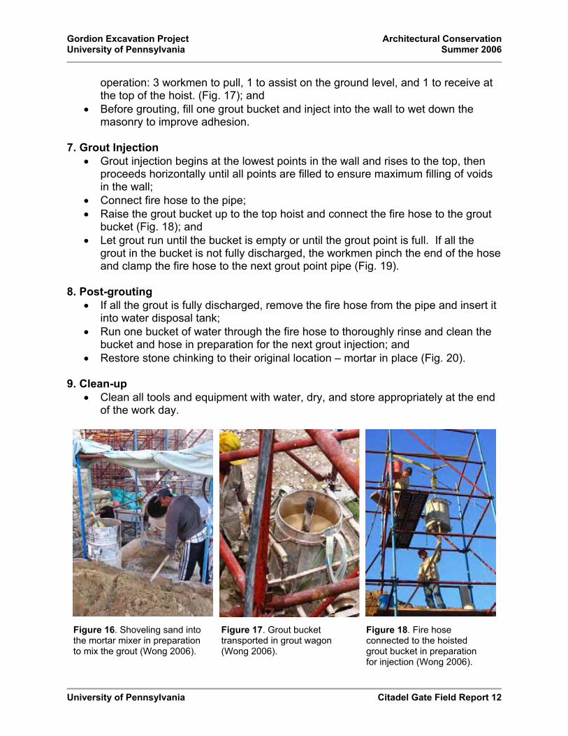
Gordion Excavation Project Architectural Conservation University of Pennsylvania Summer 2006
University of Pennsylvania Citadel Gate Field Report 12
operation: 3 workmen to pull, 1 to assist on the ground level, and 1 to receive at the top of the hoist. (Fig. 17); and
� Before grouting, fill one grout bucket and inject into the wall to wet down the masonry to improve adhesion.
7. Grout Injection � Grout injection begins at the lowest points in the wall and rises to the top, then
proceeds horizontally until all points are filled to ensure maximum filling of voids in the wall;
� Connect fire hose to the pipe; � Raise the grout bucket up to the top hoist and connect the fire hose to the grout
bucket (Fig. 18); and � Let grout run until the bucket is empty or until the grout point is full. If all the
grout in the bucket is not fully discharged, the workmen pinch the end of the hose and clamp the fire hose to the next grout point pipe (Fig. 19).
8. Post-grouting � If all the grout is fully discharged, remove the fire hose from the pipe and insert it
into water disposal tank; � Run one bucket of water through the fire hose to thoroughly rinse and clean the
bucket and hose in preparation for the next grout injection; and � Restore stone chinking to their original location – mortar in place (Fig. 20).
9. Clean-up � Clean all tools and equipment with water, dry, and store appropriately at the end
of the work day.
Figure 16. Shoveling sand into the mortar mixer in preparation to mix the grout (Wong 2006).
Figure 17. Grout bucket transported in grout wagon (Wong 2006).
Figure 18. Fire hose connected to the hoisted grout bucket in preparation for injection (Wong 2006).

Gordion Excavation Project Architectural Conservation University of Pennsylvania Summer 2006
University of Pennsylvania Citadel Gate Field Report 13
C. Micro Grout Injection for Crack Repairs
To treat surface and through masonry cracks found at the Citadel Gate complex, a micro grout injection program was implemented as part of the 2006 Site Conservation Program.
Procedure
1. Identification � Mark areas of detachment or cracks for grouting. In 2006, these areas were
marked with multi-colored neon stickers, green for grout and pink for mortar applications.
2. Documentation� Document areas to be treated on photo montaged elevations.
3. Mixture
Grout Mixture (by volume)
Mixture Lime Putty Sand Brick Dust Binder: Agg Micro Grout 2 1 1 1 : 1
HHL – Hydrated Hydraulic Lime Lime Putty – Hydrated Lime Agg - Aggregate
Figure 20. A mason repointing chinking stones after grout injection (Wong 2006).
Figure 19. Grout discharged from the bucket and discharged into the wall (Wong 2006).

Gordion Excavation Project Architectural Conservation University of Pennsylvania Summer 2006
University of Pennsylvania Citadel Gate Field Report 14
Only the brick dust and sand sieved through a No. 40 ASTM standard sieve (passing particles < 420 μm) was used for the micro grout injection. If the grout mixture did not pass through a #10 metal cannula, the brick dust and sand sieved through a No. 200 ASTM standard sieve (particle passing < 75 μm) collected in the pan was used.
4. Dry Cleaning � Clean crack area out with tools (e.g. brush, pointer, trowel) to remove debris.
5. Wet Cleaning � Clean area/crack with water using a syringe (Fig. 21); and � Place syringe at top of area of detachment or crack, allowing water to flow down
and flush out debris, soil, sand, etc. Watch the direction of water flow which indicates the route of grout flow. Water is also used to improve adhesion between the grout and the original masonry (limestone) surface.
6. Area Preparation� Fill crack with either cotton (to prevent grout from seeping out) using a wooden
stick or cosmetic sponge by hand (Fig. 22). The syringe will penetrate the cotton or sponge for the grout injection.
7. Grout Preparation � Mix grout by hand (first mixing the dry components – sand and brick dust, then
add lime putty – using sufficient water for good flow/viscosity) for at least 10 minutes before injection. See previous section 3. Mixture for grout mixture proportions; and
� Use the “finger test” to determine if the grout is well mixed. When well mixed, the grout should coat and adhere to your finger (Fig. 23).
8. Grout Injection � Start grouting from upper portions of the wall and work downwards to prevent
water used for the wet cleaning to flow over previously grouted areas; � Use a separate syringe from wet cleaning for injection of the grout; � Fill the large (60 ml) syringe with water to rinse; � Then fill the syringe ¾ full with grout (use a metallic pin to clear the opening
if/when it becomes obstructed); � Insert cannula through the cotton or above the cosmetic sponge before
discharging grout from the syringe (Fig. 24); � Start grouting from the bottom of the area of detachment or the crack.� Observe where the grout flows; � Remove the syringe needle and cover application hole with finger to prevent
grout from flowing out; and � Grout upwards along the area of detachment or crack. The goal is to have a
continuous line of grout, not separate patches of grout in the concerned area.

Gordion Excavation Project Architectural Conservation University of Pennsylvania Summer 2006
University of Pennsylvania Citadel Gate Field Report 15
9. Post-grouting � Leave the cotton in place until grout has set (ranges from minutes to hours).
10. Clean-up � Wash the used grout syringe and cannula between applications and at the end of
the workday with clean water; � Leave the grout syringes filled with water overnight; and � If blocked, fully immerse used cannula in 5% formic acid solution.
Figure 21. (Left) Wet cleaning crack with water to flush out debris (Cleary 2006).
Figure 22. (Right) Filling crack with cotton to contain grout while it sets (Cleary 2006).
Figure 23. (Left) Using the “finger test” to evaluated the consistency of the grout (Cleary 2006).
Figure 24. (Right) Injecting grout into the crack after penetrating cotton with the cannula (Cleary 2006).

Gordion Excavation Project Architectural Conservation University of Pennsylvania Summer 2006
University of Pennsylvania Citadel Gate Field Report 16
D. Removal and Storage of Loose Masonry Spalls
Visible loose masonry spalls from the Northeast elevation of the South Court were removed and stored indoors for future conservation treatment. Masonry spalls are scheduled for reattachment by mechanical pinning next season.
Procedure
1. Documentation� Record location of loose masonry spall on a photo elevation.
2. Removal � Remove the loose masonry piece from its original location (Fig. 25). � Label both the back side of the spall and the corresponding location it was
removed from with the same name (it may be helpful to indicate UP/DOWN direction to facilitate future reattachment).
3. Storage � Insert each piece of masonry into a plastic bag along with a label indicating the
name of the removed piece, the location where it was removed from, the date of removal, and the title of the project; and
� Lay plastic bags in a container and store container in a visible and protected area in the Excavation House. Additionally, place a copy the graphic documentation and matrix at the bottom of the container. In summer 2006, the container was stored on a shelf in the front office of the Excavation House.
4. Graphic Representation and Matrix� Create a digital graphic representation (photo elevation) showing the specific
locations where the loose masonry spall pieces were removed and a matrix showing the name of the removed piece, its original location, where it was stored, and any additional notes. See Appendix D. Masonry spalls removed and stored.
Figure 25. Area where masonry spall piece “D” was removed from on the Northeast elevation of the South Court (Wong 2006).

Gordion Excavation Project Architectural Conservation University of Pennsylvania Summer 2006
University of Pennsylvania Citadel Gate Field Report 17
E. Crack Gauges for Monitoring Wall Deformation
Self-made crack guages can be used as a simple, low-cost technique to monitor movement within a structure. This concept was applied using available materials found at the site.
Procedure
1. Prepare Crack Monitors � Cut plastic into small rectangular pieces [each crack monitor consists of two
pieces] (Fig. 26); and � Overlap one piece over the other and mark the location from which monitoring
will begin using a box-cutter or similar tool.
2. Mix Mortar for Adhesion� Mix enough mortar for adhering crack monitor pieces to the masonry unit.
3. Installation of Crack Monitors� Adhere the outer end of one plastic piece to the adjacent masonry with mortar
(use mortar sparingly). It may be necessary to hold each piece in place until the mortar initially sets before continuing with the second piece;
� Repeat adhesion of second piece in the same manner but make sure to align the pieces at the marked location from which the monitoring will begin; and
� Return in a few hours to check the alignment of the monitoring pieces (Fig. 27).
4. Monitoring � Monitor movement by evaluating whether the pieces have moved away or toward
each other from the marked location.
Figure 26. Plastic pieces used for crack gauges (Wong 2006).
Figure 27. Attached crack gauges on the South Court Northeast elevation (Wong 2006).

Gordion Excavation Project Architectural Conservation University of Pennsylvania Summer 2006
University of Pennsylvania Citadel Gate Field Report 18
F. Setting Project Parameters
Project parameters should be established in order to define appropriate conservation measures for stabilizing the Citadel Gate complex.
Procedure
1. Set Project Parameters � Determine the goals of the stabilization effort at the Citadel Gate – whether it is to
protect against natural deterioration or seismic activity? Decide if the Citadel Gate will be accessible to the public for interpretation of the Citadel Mound.
2. Structural Analysis � Regardless of the goal, a structural analysis by a structural engineer with
experience in the preserving historic structures under seismic activity to determine if the structure meets current codes should be undertaken.
3. Design Proposal � Determine the project budget for stabilization. � Design proposals submitted by a team of preservation architects/engineers
should reflect the desired goal and budget for stabilizing the Citadel Gate.
4. Conservation and Maintenance Plan � Establish a conservation and maintenance plan based on determined goals and
stabilization efforts.

Gordion Excavation Project Architectural Conservation University of Pennsylvania Summer 2006
University of Pennsylvania Field Report 19
IV. OBSERVATIONS
The Early Phrygian Citadel Gate is located on southeastern edge of the Citadel Mound at the archaeological site of Gordion. The Gate complex is current composed of three separate elements, a central east-west oriented ramp flanked by the rectangular North and South Court buildings aligned with the exterior fortification walls of the Old Citadel.Exposed and visible areas found today include the entire North Court structure, the South Court exterior, and the overall central ramp area. Remains of a later Middle Phrygian gate (as part of the New Citadel) are found sporadically on tops of both the North and South Court buildings, as well as on top of the rubble fill glacis at the Gate entrance (east of the complex). Northeast of the Gate complex,
A. Current Conditions
The following descriptions are based on the Conditions Survey conducted in summer 2006. Conditions were recorded on acetate covered photo-rectified elevations (see Appendix A. Conditions Survey). The survey was divided into North Court and South Court buildings and then into sub-categories of Roof, Exterior Elevations, and Interior Elevations where accessible and/or visible during the field investigation.
Situated in front of the entrance of the Citadel Gate is the rubble fill glacis (Fig. 28). This mass abuts the exterior east elevation of the North Court without any angle of repose (it sits relatively vertical) and appears dangerously unstable. It appears that what is more critical than the stabilization of the Citadel Gate complex itself is the containment, consolidation, or removal of this rubble fill.
Figure 28. Rubble fill glacis in front of the Citadel Gate entrance (Wong 2006).

Gordion Excavation Project Architectural Conservation University of Pennsylvania Summer 2006
University of Pennsylvania Field Report 20
1. North Court
a. Roof / Concrete CappingThe North Court walls are covered with a concrete capping installed in 1988 which replaced the original 1956 capping. The 1988 capping was designed to drain water more efficiently and is in fair condition.
The capping slopes to drain at several points on the roof. However, the plastic and metal pipe drains are in poor condition and water does not drain properly from the structure. Currently, water funneled through the pipe drains either pour straight onto the rubble masonry piled against the east elevation or directly along the south interior elevation of the North Court. The second condition can create standing water at the base of the wall and contributes to biological growth found on the wall in this area, as well as along the top courses of the structure where water does not drain properly. The drainage system is inadequate for removing water from the wall tops. Moreover, the lower walls (e.g. north wall) which step down to grade show signs of disintegrated wall cores immediately beneath the concrete cap.
Visible past repairs using a silicone sealant to patch cracks and detachment from adjacent masonry are found throughout the capping. In 1996, cracks found mainly between the sections of the capping at the North Court were repaired with a locally available silicone sealant (Silikon Mastik 29-11-95 manufactured by Henkel Kalitesi �le)by architectural conservator Evan Kopelson [Kopelson field notebook 1996)]. New cracks, openings, and detachment areas have formed since this last conservation effort (Fig 30).
Figure 29. North Court roof plan (Wong 2006). Figure 30. New opening next to a previous repair at the North Court roof capping (Wong 2006).

Gordion Excavation Project Architectural Conservation University of Pennsylvania Summer 2006
University of Pennsylvania Field Report 21
b. Exterior Elevations The North Court’s exterior walls are in fair to poor condition and have not been consolidated by injection grouting.
North Elevation In general, the north exterior elevation of the North Court is in fair condition only because it is a low free standing wall. The wall steps down from east to west. Improper drainage of water at the base of the upper (eastern) portion of the wall has caused erosion, as well as formation of gypsum salts. East of the Middle Phrygian remains, the masonry units appear haphazardly assembled or displaced. The center section of the wall is capped with concrete where the wall steps down to grade. This is an area of concern. Biological growth is also prevalent in this section as a result of water running off the capping and onto the masonry surface. The upper (eastern) area of this center section is an area of concern; it may be a vulnerable location for water collection and intrusion due to improper drainage. This may contribute to the hollow areas immediately beneath the concrete capping, revealed by tapping on the concrete, as well as the bulge forming on the north interior elevation of the North Court. Additionally, missing areas masonry units as well as deteriorated stones at the center section was also observed.
Figure 31. North exterior elevation at the North Court (Wong 2006).
Gordion Excavation Project Architectural Conservation University of Pennsylvania Summer 2006
University of Pennsylvania Field Report 22
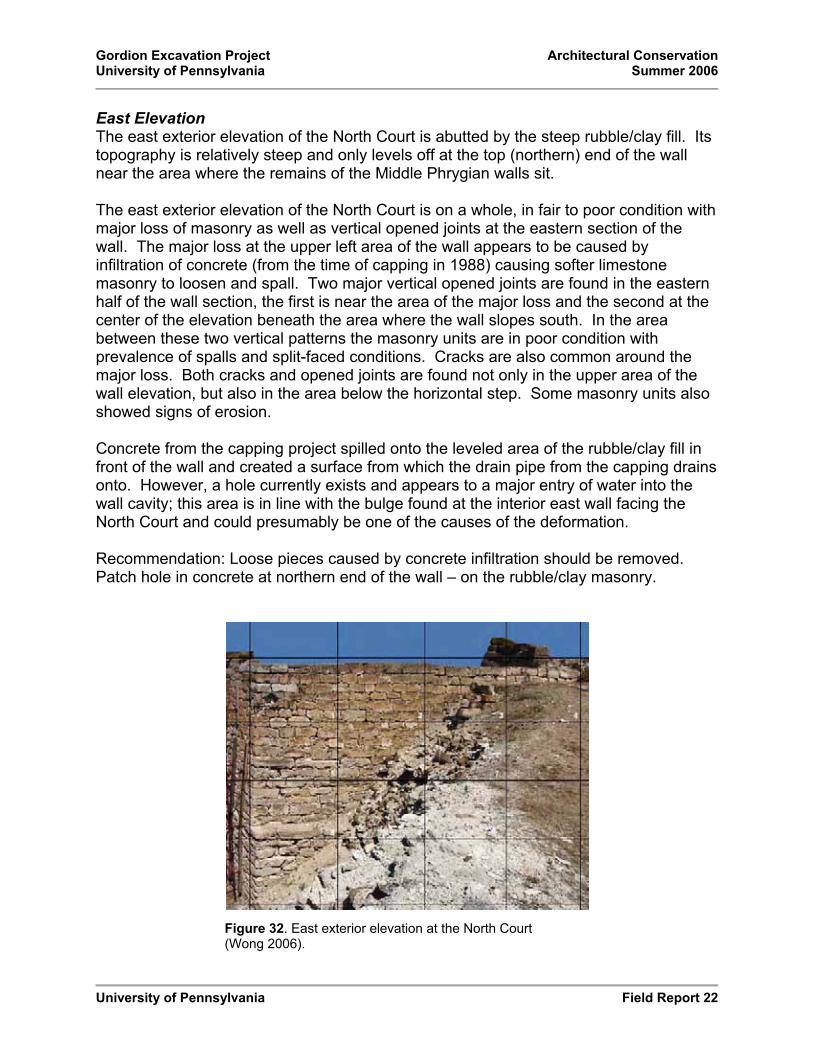
East Elevation The east exterior elevation of the North Court is abutted by the steep rubble/clay fill. Its topography is relatively steep and only levels off at the top (northern) end of the wall near the area where the remains of the Middle Phrygian walls sit.
The east exterior elevation of the North Court is on a whole, in fair to poor condition with major loss of masonry as well as vertical opened joints at the eastern section of the wall. The major loss at the upper left area of the wall appears to be caused by infiltration of concrete (from the time of capping in 1988) causing softer limestone masonry to loosen and spall. Two major vertical opened joints are found in the eastern half of the wall section, the first is near the area of the major loss and the second at the center of the elevation beneath the area where the wall slopes south. In the area between these two vertical patterns the masonry units are in poor condition with prevalence of spalls and split-faced conditions. Cracks are also common around the major loss. Both cracks and opened joints are found not only in the upper area of the wall elevation, but also in the area below the horizontal step. Some masonry units also showed signs of erosion.
Concrete from the capping project spilled onto the leveled area of the rubble/clay fill in front of the wall and created a surface from which the drain pipe from the capping drains onto. However, a hole currently exists and appears to a major entry of water into the wall cavity; this area is in line with the bulge found at the interior east wall facing the North Court and could presumably be one of the causes of the deformation.
Recommendation: Loose pieces caused by concrete infiltration should be removed.Patch hole in concrete at northern end of the wall – on the rubble/clay masonry.
Figure 32. East exterior elevation at the North Court (Wong 2006).

Gordion Excavation Project Architectural Conservation University of Pennsylvania Summer 2006
University of Pennsylvania Field Report 23
Southeast ElevationThe limestone wall at the southeast exterior elevation of the North Court is in fair condition, however requires repairs and filling of missing areas. There are two major problem areas where vertical opened joints are coupled with deformation of masonry units. The first area is at the bottom third of the elevation and the second area is found at the upper right area of the elevation near the major loss. A prominent vertical opened joint is also found near the left (western) edge of the wall as a vertical pattern of masonry cracks at the right (eastern) edge of the wall.
Major loss at the upper right area of the wall is related to the major loss found at the east exterior elevation, caused also by the spilling of concrete (from the capping project in 1988). Another area of major loss at the bottom right of the wall has existed since it was excavated in 1955 [Photo GB55-56]; although after careful inspection masonry units may have moved slightly from handling.
Original plaster was found near the base of the wall below the area where the Middle Phrygian wall sits. Cracks were also prevalent immediately beneath the Middle Phrygian walls as a sign of stress caused by the additional weight of the masonry.
Figure 33. Southeast exterior elevation at the North Court (Wong 2006).

Gordion Excavation Project Architectural Conservation University of Pennsylvania Summer 2006
University of Pennsylvania Field Report 24
West Return Elevation Overall, the west return at the south elevation of the North Court is in good condition. A slight slope north towards the inner court is found at the top of the wall as well as the vertical joint pattern along the northern (left) edge. Only two areas of spalls and some split-faced conditions found on masonry units were observed. The masonry units interlock with the southwest wall.
Figure 34. West return exterior elevation at the North Court (Wong 2006).

Gordion Excavation Project Architectural Conservation University of Pennsylvania Summer 2006
University of Pennsylvania Field Report 25
Southwest Elevation The southwest elevation appears to be in good condition. While the western section of the wall was first reconstructed in 1955 and then again in 2006, the bottom eastern section remained from the time of excavation. Visible differences between the reconstructed and original masonry units are found in their tool marks. East of this area is a large opened joint pattern. Masonry units found at the bottom courses are deteriorated (mainly eroded). Biogrowth is found only at the tops of the wall. A few missing chinking stones and cracks are found throughout the wall.
Figure 35. Southwest exterior elevation at the North Court (Wong 2006).

Gordion Excavation Project Architectural Conservation University of Pennsylvania Summer 2006
University of Pennsylvania Field Report 26
c. Interior Elevations Overall, the interior elevations of the North Court are in good condition. Cracks and a significant bulge found at the east elevation require attention.
North Elevation The masonry north interior wall is in good condition, with the exception of a slight bulge and cracks found at the bottom right section. The bulge begins approximately 120cm from the eastern edge and the vertical crack pattern occurs within the area of the bulge and the eastern (right) edge of the wall. The bottom masonry courses where the ground dips below grade [at the center of the wall] are deteriorated and eroded. Additionally, a small area of original earthen plaster is still visible where the bulge exists.
Figure 36. North interior elevation at the North Court (Wong 2006).

Gordion Excavation Project Architectural Conservation University of Pennsylvania Summer 2006
University of Pennsylvania Field Report 27
East Elevation The east interior elevation of the North Court is an area of concern, in fair to poor condition. A significant bulge starting approximately 285 cm above grade up found at the northern portion (left) of the wall is coupled by severe cracking in its immediate area. Vertical crack patterns are prevalent directly under the area where the remains of Middle Phrygian walls still sit. Cracks are generally split-faced and found loose in this area of stress. Beginning from the bulge on the north, the entire elevation seems to tilt slightly inward (west) toward the open court. Moreover, an area of heavily eroded masonry is found at the bottom northern corner of the wall.
Figure 37. East interior elevation at the North Court (Wong 2006).

Gordion Excavation Project Architectural Conservation University of Pennsylvania Summer 2006
University of Pennsylvania Field Report 28
South Elevation In general, the south interior wall is in good condition. Like the east interior wall, cracks are visible immediately beneath the area where the remains of the Middle Phrygian walls sit. A vertical opened joint pattern at the eastern (left) end of the wall is found in the same areas as vertical cracks. The area directly below the metal drainpipe from the roof is heavily covered with biological growth.
Figure 38. South interior elevation at the North Court (Wong 2006).

Gordion Excavation Project Architectural Conservation University of Pennsylvania Summer 2006
University of Pennsylvania Field Report 29
2. SOUTH COURT
a. Roof / Wall Capping Like the North Court, the South Court also has a concrete cap placed in 1988 and is in poor condition. Although the majority of the capping is sloped west to drain, water also drains directly onto rubble masonry and the exterior east face of the structure at the southeast. In a portion of the southeast area not connected to the main concrete capping, a few concrete sections have broken off and sit precariously on the rubble masonry near the exterior east elevation of the South Court.
Two different past repairs are found throughout the capping to seal cracked openings, the first with a silicone sealant in 1988 and second, probably later (found on top of the silicone) a harder white (most likely a concrete or lime mortar). In several areas, these repairs have failed and openings have formed, as well as small new cracks in their vicinity. Spalls are also found, the largest at center where the capping appears flat without a slope for draining water.
Large separations from the adjacent masonry and openings (average + 1-5 cm) are prevalent, especially in the western section of the capping where the wall steps down toward the ground. This area is in a particularly poor condition. Where detachment has occurred, warping of the concrete is visible causing greater separation from the cap and the adjacent masonry. Additionally, openings permitting visual investigation as well as tapping on the concrete both reveal hollow areas immediately beneath the capping found along the steps of the western section.
Figure 40. This illustration shows the two different past repairs; the hard lime mortar over the silicone sealant (Wong 2006).
Figure 39. South Court roof plan (Wong 2006).

Gordion Excavation Project Architectural Conservation University of Pennsylvania Summer 2006
University of Pennsylvania Field Report 30
b. Exterior Elevations The exterior walls of the South Court in poor condition and is currently undergoing a grout injection program for its stabilization.
Northeast Elevation Facing the central ramp, the northeast elevation of the South Court is the most deteriorated and vulnerable area of the Citadel Gate complex. A considerably large bulge at the upper center area of this face originally caused concern in 1987 and initiated the formal grout injection program in 2001 to stabilize the structure. (It is uncertain when the bulge first formed.) Investigation of the area behind the bulge from the west return wall showed considerably large voids (Fig. 42) immediately behind the masonry veneer where the masonry core has settled and causing the wall to buckle.The bottom third of the northeast elevation has been grouted; however the area immediately around the bulge is still untreated. Several split faced and through masonry cracks found in the previously grouted area were treated with micro grout injections in summer 2006. Presence of efflorescence was found at the base of the elevation.
Cracks and horizontal opened joints are commonly found throughout the northeast elevation and are especially prevalent in the area of the bulge. Additionally, split-faced masonry surfaces and large spalls in the upper courses are visible. At the eastern edge of the wall, masonry units are in poor condition with large cracks and loose masonry. A vertical opened joint pattern is also found along this edge. One intact glass tell-tale was found across this opened joint. Several nails for plumbline measurements still exist across the northeast elevation. Furthermore, where the current scaffolding assists in stabilizing the Citadel Gate structure, wooden shims inserted between the scaffolding and the structure may be causing stress on the masonry surfaces.
Figure 42. The void behind the bulge found at the South Court Northeast exterior elevation (Wong 2006).
Figure 41. Northeast exterior elevation at the South Court (Wong 2006).

Gordion Excavation Project Architectural Conservation University of Pennsylvania Summer 2006
University of Pennsylvania Field Report 31
West Return ElevationThe west return at the South Court north elevation is overall in poor condition due mainly to its proximity to large bulge on the northeast elevation. At the upper third of the west return is a bulge and an area of major loss. Spalled masonry units and surrounding cracks are found in this area. Immediately beneath the bulge along the northern edge of the wall is a large vertical opened joint pattern (probably caused by the northeastern wall detaching from the rubble core). According to photo GB55-49, this opened joint pattern has existed since 1995; however, the area of separation is much greater today. Nine courses down from the top is a broken glass tell-tale found across this joint. Investigation of this opened joint showed extremely large voids behind the northeast elevation wall – most of the rubble masonry has settled and shifted from their original location. Spalls and split-faced unit masonry was also characteristic throughout the west return. While the bottom third of the wall has been consolidated by injection grouting, the top of the wall slopes southward. The masonry units interlock with the northwest wall.
Figure 43. West Return elevation at the South Court (Wong 2006).
Figure 44. Area of major loss at the upper right corner of the South Court west return wall (Wong 2006).

Gordion Excavation Project Architectural Conservation University of Pennsylvania Summer 2006
University of Pennsylvania Field Report 32
Northwest Elevation
By the end of the 2006 season, the bottom two thirds of the northwest elevation at the South Court have been consolidated by grout injection. The following comments include observations of the conditions before the grouting commenced.
In general, the northwest elevation at the South Court is in fair condition. Several opened joints, both horizontal and vertical patterns alike are prevalent in the upper half of the elevation. Opened joints in this area may result from the same circumstances as the northeast elevation (of the South Court) where the bulge has occurred; the possibility of the rubble masonry sliding immediately beneath the concrete capping.
Two areas where cracks are common are found at the center right (western edge) area of the wall and the entire bottom third of the elevation. These cracks appear to be mainly aesthetic, surface cracks found on the masonry units which can be repaired by micro grout injections. Presence of efflorescence was found at the bottom center of the elevation. An area of great deterioration, specifically showing eroded masonry units, is at the bottom left corner of the protruding ledge where water appears to drain.
Figure 45. Northwest exterior elevation at the South Court (Wong 2006).

Gordion Excavation Project Architectural Conservation University of Pennsylvania Summer 2006
University of Pennsylvania Field Report 33
East Elevation The east exterior elevation of the South Court is the exterior wall on the left visible from the entrance to the Citadel Gate complex. Battered on the north, the east elevation is free standing on the north edge, bermed against rubble fill on the south, and constructed with two ledge extensions at the bottom of the structure. Only the upper ledge is fully exposed while the lower one sits partially visible adjacent to the central ramp.
In general, the east wall is in poor condition. Three problem areas exist on this elevation: the first two at the center section and the third along the northern edge. In first two problem areas the tops of the wall are depressed and water draining from the capping has caused masonry units to shift and disintegrate. A slight bulge is visible at the bottom (right) of the second area. Vertical opened joint patterns appear in the second and third problem areas, most likely the result of structural movement.Additionally, cracks are common in the areas immediately around the vertical opened joints. Although the bottom portion of the wall was consolidated by injection grouting in 2001 (confirm date) and appears to be in good condition, many cracks are visible in this location. A few spalls as well as eroded masonry units are also found throughout the elevation.
Figure 46. East exterior elevation at the South Court (Wong 2006).

Gordion Excavation Project Architectural Conservation University of Pennsylvania Summer 2006
University of Pennsylvania Field Report 34
South Elevation Very little of the south elevation is visible while the majority of the South Court is still unexcavated. Overall, the south elevation is in good condition. With the concrete capping to the north, the south elevation acts primarily as a parapet wall with concrete over its top. The wall is not continuous and its elevation not completely level; the center portion of the wall slopes down towards the east. Almost all chinking stones are missing causing large opened joints between masonry units. Although eroded stones, spalls, and through stone cracks are found, these conditions are not prevalent. Little biogrowth is found at the top edges of the wall. Vegetation is found at the west end of the wall where water drains into the rubble fill to its south.
Figure 47. North exterior elevation at the South Court (Wong 2006).
Gordion Excavation Project Architectural Conservation University of Pennsylvania Summer 2006
University of Pennsylvania Field Report 35
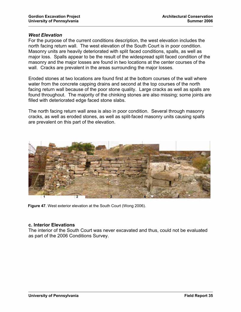
West Elevation For the purpose of the current conditions description, the west elevation includes the north facing return wall. The west elevation of the South Court is in poor condition. Masonry units are heavily deteriorated with split faced conditions, spalls, as well as major loss. Spalls appear to be the result of the widespread split faced condition of the masonry and the major losses are found in two locations at the center courses of the wall. Cracks are prevalent in the areas surrounding the major losses.
Eroded stones at two locations are found first at the bottom courses of the wall where water from the concrete capping drains and second at the top courses of the north facing return wall because of the poor stone quality. Large cracks as well as spalls are found throughout. The majority of the chinking stones are also missing; some joints are filled with deteriorated edge faced stone slabs.
The north facing return wall area is also in poor condition. Several through masonry cracks, as well as eroded stones, as well as split-faced masonry units causing spalls are prevalent on this part of the elevation.
c. Interior Elevations The interior of the South Court was never excavated and thus, could not be evaluated as part of the 2006 Conditions Survey.
Figure 47. West exterior elevation at the South Court (Wong 2006).

Gordion Excavation Project Architectural Conservation University of Pennsylvania Summer 2006
University of Pennsylvania Field Report 36
V. TREATMENT PROGRAM
This portion of the report, the Treatment Program discusses the applicability of the six conservation tasks outlined in the previous Methodology section.
A. Conditions Survey
A full conditions survey of Citadel Gate complex was conducted in summer 2006 including (where visible) the interior and exterior elevations as well as the roof cappings for both the North and South Court structures. The survey was completed over a period of four weeks by a team of two people, an architectural conservator from the US (Kelly H. Wong) and a graduate student intern from Middle Eastern Technical University in Ankara, Turkey (Gülsün Özkan). An on-site conditions survey documenting the current conditions of the Citadel Gate complex is important in the overall understanding of the decay mechanisms as well as enabling proposal of appropriate recommendations for treating problem areas of an existing structure.
Analysis Survey results showed prevalence of vertical opened joint patterns (Fig. 49) as well as cracks (Fig. 50) near the areas of wall deformation (e.g. bulges), split-faced conditions where spalls were commonly found, erosion of masonry units caused by improper water drainage, and major loss as a result of several factors.
Locations where opened joint patterns were found are indicated as problem areas because of their relationship to differential movement in the structure. Differential movement may be a result of ground settlement beneath the structure or by horizontal seismic movement due to the site’s proximity to the Northern Anatolian Fault Line, one of the most active right-lateral strike-strip faults in the world [Wong 2006, 152]. The horizontal movement shifts masonry units away from each other, creating a vertical pattern. On the other hand, where the rubble core masonry disintegrates and slides within the exterior veneer, rolling up of individual masonry units creates an enlarged horizontal opened joint, and in some circumstances can lead to bulges. Similarly in 1999, structural engineer Conor Powell speculated that the deformation was caused by rotational slump, an outward collapse of the base [Goodman 1999, 5]. Problem areas found in summer 2006 include:
� North Court: Exterior East, Southeast and North elevations, Interior East and North elevations and Roof capping � South Court: Exterior East, Northeast, and West Return elevations and
Roof capping
Cracks were also common, both surface and through masonry were found in stressed areas such as locations near deformations (e.g. bulges and major loss), beneath Middle Phrygian remains due to additional weight, and at outer corners of the structure where load is distributed.

Gordion Excavation Project Architectural Conservation University of Pennsylvania Summer 2006
University of Pennsylvania Field Report 37
Problems/Concerns
Measured Drawings Photo rectified elevations were used as base documents for the conditions survey and are only representational. Measured drawings were not required, nor possible due to time constraints. However, if measured drawings are required in the future, large format photography should be taken to provide accurately scaled elevations. Measured drawings can be useful in calculating the total area of a specific condition requiring treatment.
Photos
Figure 49. Vertical opened joint condition found at the South Court West return elevation (Wong 2006).
Figure 50. Cracks found beneath the Middle Phrygian Wall at the East interior elevation at the North Court (Wong 2006).

Gordion Excavation Project Architectural Conservation University of Pennsylvania Summer 2006
University of Pennsylvania Field Report 38
B. Grout injection for stabilization (South Court Northwest elevation)
An injection grouting program to stabilize the Citadel Gate complex officially began in 2001 after structural scaffolding was erected. In summer 2006, a team of three masons from the local town of Polatli and five workmen from within the Village of Yassihöyük focused on the central section of the Northwest elevation of the South Court. Over a period of ten work days, they completed two lifts with the exception of repointing the lower left portion of the grouted area (Figs. 51 & 52). This area should be repointed next season (2007) to establish visual integrity of the structure. A total of 12,185 liters of grout was used in summer 2006.
1. Material Specification
� Hydrated Hydraulic Lime (HHL) The hydrated hydraulic lime used for the grout and mortar mixtures is a Lafarge ChauxBlanche NHL 3.5-Z, a “moderately hydraulic” lime by EU Norm EN 459 standards.According to Lafarge France, the natural hydraulic limes are burned and slaked argillaceous or siliceous limestone which are reduced to powder with or without grinding. Additions of suitable pozzolanic or hydraulic materials (up to 20%) made to the natural hydraulic limes are designated NHL-Z.
This product has seen widespread use in experimental laboratory programs in past research, especially throughout continental Europe. The hydrated hydraulic lime has shown lower strength and alkali content than other hydraulic limes and lower alkali content in comparison to Portland cement, making it suitable for grouting [Ferragani et al. 1984, 111].
� Lime Putty – (Normal Kireç)The lime putty was made by immersing hydrated slate granulated calcium lime made in June 2006 (by Kireç Ba�tas, Söndürülmüs Toz, Kalker Kireci S.KK 70-T) into water for a few weeks before use. The calcium lime is distributed by Dundar Ticarte, a local distributor in Polatli.
� Sand – (Kum) Sand used for the mixtures was from the local Sirrihisar province and also distributed by Dundar Ticarte.
� Brick Dust – (Kiremit) Brick dust is purchased from a local brick factory in Polatli that crushes their low-fired (below 950ºC) bricks during the winter specifically for Gordion. The amount crushed is based on the amount requested at the end of the previous season.

Gordion Excavation Project Architectural Conservation University of Pennsylvania Summer 2006
University of Pennsylvania Field Report 39
Problems/Concerns
Structural Analysis A formal structural analysis by an engineer with experience in stabilizing historic structures is critical before continuation of injection grouting at the Citadel Gate complex in summer 2007. There are cost and safety consequences should the analysis be postponed. This analysis would enable a better understanding of the current structural integrity of the complex, the effect of grouting to the existing wall construction, and provide appropriate treatments for stabilizing each structure. The structural analysis should answer the following questions:
� Stabilization method: Is injection grouting sufficient for resisting natural deterioration or seismic activity?
� Does injection grouting meet the current need for stabilization? � What are alternative techniques for stabilization (e.g. mechanical pinning
alone or coupled with injection grouting)? � Bulge: Is injection grouting appropriate for treating the void behind the
large bulge on the Northeast elevation of the South Court? � Water drainage: Are weep holes necessary if grouting?
Photos
Figure 51. Northwest elevation at the South Court after grouting is complete in summer 2006 (Wong 2006).
Figure 52. Repointing not yet completed in the upper area in summer 2006 (Wong 2006).

Gordion Excavation Project Architectural Conservation University of Pennsylvania Summer 2006
University of Pennsylvania Field Report 40
C. Micro grout injection
As a result of the conditions survey, a micro grout injection program for treating surface and through masonry cracks began at the Citadel Gate complex in summer 2006. Masonry cracks too large for grout injection will be filled with mortar next season.Moreover, grout injections were finished with a recessed 90º angle to enable filling the outer portion with mortar (also next year) to match the color of the adjacent masonry units.
The East and Northeast exterior elevations of the South Court were selected as the pilot areas in order to assess in the following year whether the micro grout injections were successful in meeting requirements for both structural and visible integration. Over a one month period, more than 76 cracks were treated by a team of three architectural conservators and a graduate student intern.
Problems/Concerns
EfflorescenceIn the areas of or around micro grout injection, it was noted that the presence of efflorescence appeared (several days later) after water was used to flush out the debris in preparation for the micro grout injections (Fig. 53). It is important to use the water sparingly to avoid contributing to the development of salts to prevent further deterioration of the masonry units.
Grout Color The color of the grout used for the crack repairs initially dries pinker than the adjacent masonry because of the volume of crushed brick used in the formulation (Fig. 54).Crushed brick was used for its color, durability, availability, and consistency with the grout formulation used for the stabilization program. The color is expected to fade, becoming more consistent with the adjacent masonry surface. However, should the color remain unchanged, a layer of mortar can be applied the following year to match the color.
Equipment Equipment necessary for sieving the materials on site was not sufficient. High quality grouts result from adequate sieving. However, insufficient sieving equipment produced a lower quality grout which made filling the large syringes difficult. Additionally, the short supply of syringes (plastic, 60 ml) wore out the available “disposable” ones. For efficacy, a set of ASTM standard sieves and a larger supply of large plastic 60 ml syringes should be purchased and stored on site to facilitate the process in the future.

Gordion Excavation Project Architectural Conservation University of Pennsylvania Summer 2006
University of Pennsylvania Field Report 41
Photos
Figure 53. Efflorescence present a few days after flushing an area above with water (Wong 2006).
Figure 54. Color of grout after setting appears pinker than adjacent masonry unit (Wong 2006).

Gordion Excavation Project Architectural Conservation University of Pennsylvania Summer 2006
University of Pennsylvania Field Report 42
D. Removal and storage of masonry spalls (South Court Northeast elevation)
A total of five loose masonry pieces (spalls) were removed from its original location at the Northeast elevation of the South Court, labeled Spalls A, B, C, D, and E. Spalls A, B, C, and E were removed from the site, labeled and inserted in plastic bags (placed in a pink plastic container), and stored on a shelf in the outer office of the Excavation House for future pinning. Storage of spalls for future treatment (e.g. mechanical pinning) can prevent the loss of valuable cultural fabric as well as retaining aesthetic integrity of a significant monument. Due to its large size, Spall D was left on site, on top of the roof capping and in line with the location of the spall. See Appendix D for details.
Problems/ConcernsBoth the stored spalls and spalled area of the masonry units should be examined carefully to determine whether consolidation is required before reattachment by mechanically pinning. Another survey to verify whether more spalls are present should be conducted next season.
Photos
Figure 55. South Court northeast elevation showing the locations where the masonry spalls were removed (Wong 2006).
Figure 56. Matrix with the name, original location of the spall, where it is stored, and additional reference notes for the masonry spalls removed in summer 2006 (Wong 2006).

Gordion Excavation Project Architectural Conservation University of Pennsylvania Summer 2006
University of Pennsylvania Field Report 43
E. Crack monitors
In order to monitor movement of masonry units near areas of wall deformations, three crack gauges were installed at the South Court – two at the northeast elevation and one at the west return. Each crack gauge consists of two small overlapping rectangular plastic pieces adhered to the masonry units at their outer ends with mortar. The overlapping areas will measure the movement in the joint openings at three locations (one vertical and two vertical joints).
Problems/ConcernsDue to the make-shift quality of these crack monitors, this approach may not provide precise measurements but indicate only overall movement in the areas monitored.There was difficulty attaching the plastic monitor pieces to the mortar adhesive and consequently the complication of perfectly aligning the pieces for each crack monitor.
Photos
Figure 57. South Court west return elevation where one vertical crack gauge was installed (Wong 2006).
Figure 58. South Court northeast elevation where two crack gauges were installed to monitor one vertical and one horizontal joint (Wong 2006).
Gordion Excavation Project Architectural Conservation University of Pennsylvania Summer 2006
University of Pennsylvania Field Report 44
F. Project Parameters
Establishing project parameters is critical in the conservation of any historic structure. In the case of the Citadel Gate, parameters will assist in the proposal of an appropriate design for stabilizing the complex depending on current and future goals as well as the constraints of a project budget. Project parameters should also include the importance for a conservation and maintenance plan for the future of the Citadel Gate complex.
In discussions with two structural engineers, Sureya Ural from Turkey and Nels Roselund from the US, both recommended first addressing the goal of the stabilization – whether it is to protect the complex against natural deterioration or against seismic activity. Additionally, if the interpretation of the Citadel Mound enables the public to walk through the Citadel Gate, the issue of public safety should also be addressed in the stabilization design and effort.
To prevent the future loss of historic fabric, decisions should also be made before the start of the next season in order to allow enough time to establish a properly planned conservation and maintenance plan for the future stabilization of the Citadel Gate complex. These decisions have cost implications and need to be carefully considered by the director of the Gordion Excavation Project.
Problems/ConcernsIndependent of the goals, a structural analysis is still essential before the continuation of any conservation treatment.
Photos
None.

Gordion Excavation Project Architectural Conservation University of Pennsylvania Summer 2006
University of Pennsylvania Citadel Gate Field Report 45
VI. CONCLUSIONS
Based on observations made in summer 2006, the bulge on the Northeast elevation of the South Court is likely the result of the rubble core sliding down between the masonry veneer of the wall structure (Roselund fax 2006). Large voids are apparent in this area and it is uncertain whether grout injection is the appropriate method for addressing this problem. The sliding is most likely caused by seismic movement and/or the combination of rain water and wind penetration at the sides of the structure (rather than from the top). Archival photographs show that the bulge did not exist at the time of excavation, although the area may have been vulnerable to movement and/or deformation.
Locations where wall deformations were visible such as bulges and the prevalence of cracks, opened joints (both vertical and horizontal), and deteriorated and/or major loss (including spalls) of masonry units occurred are indicated as problematic areas. These areas of concern include the following:
North Court: Exterior East, Southeast, and North elevations, Interior East and North elevations, and Roof Capping
South Court: Exterior East, Northeast, and West Return elevations, and Roof capping

Gordion Excavation Project Architectural Conservation University of Pennsylvania Summer 2006
University of Pennsylvania Citadel Gate Field Report 46
VII. RECOMMENDATIONS
Since its excavation in the 1950s, the Citadel Gate complex has seen several campaigns of conservation, from small-scale crack repairs to large-scale stabilization efforts. These treatments nevertheless have mainly been reactionary treatments, addressing immediate problems only after they occurred rather than implementing conservation measures with a long-term perspective. Reactionary conservation treatments, of course are not less significant because they are most likely necessary to save the historic fabric. However, the conservation of any historic monument should include both the short-term and long-term development of the structure by first understanding its future intent and parameters.
The reactionary approach seems to be a result of the continual change in conservation directors at Gordion, each with his or her independent ideas, approaches, and skills. The current 2006 five-year conservation plan addresses these issues, in hopes of providing a long-term and holistic approach to the preservation of the Citadel Gate.
Recommendations for the Citadel Gate complex from the field work conducted in summer 2006 are divided into Immediate, Short-Term and Long-Term.
A. Immediate (0-1 year)
Project Parameters � Establishing project parameters for the stabilization of the Citadel Gate complex
is imperative for the selection of an appropriate conservation treatment. The Gordion Excavation Project director should determine whether the goal of the stabilization is to assist the monument in resisting natural deterioration or against seismic activity. Both goals require different approaches and have varying cost implications. Other factors to consider include site interpretation, public safety, and budget constraints. Only after these parameters are ascertained can appropriate treatments be proposed, selected, and implemented. These parameters should, of course, follow the 1999 architectural conservation guidelines.
Structural Analysis � A formal structural analysis of the Citadel Gate, preferably by a local Turkish
engineer with experience in stabilizing historic structures, is vital to the conservation of the complex. The analysis should include not only an investigation of the structures, but also an evaluation of the current grout injection technique for consolidating the walls as well as whether weep holes for proper drainage (to prevent hydrostatic pressure) is necessary. Additionally, the analysis may also include proposals of alternative stabilization techniques feasible based on the parameters established by the project director.

Gordion Excavation Project Architectural Conservation University of Pennsylvania Summer 2006
University of Pennsylvania Citadel Gate Field Report 47
Roof Repairs � Cracks, past failed repairs, and holes found on the concrete cappings should be
patched with appropriate materials to prevent further water infiltration. Opened areas between the concrete and adjacent masonry should be capped to direct water away from the large openings and the structure. Serious considerations should be made for replacing the concrete cappings as rain water continues to penetrate the structures even with this covering.
� Divert water away from the East elevation of the South Court building. The masonry wall is quickly deteriorating as a result of rain water run-off (caused by concrete – hard, non-porous material) and should be remedied immediately. Repairing the spalled concrete pieces at the center of the roof could help, as well as creating an incline to help rain water slope to drain southward away from the top (northern concrete capping area) of the structure. Conservation through consolidation or reconstruction of the masonry veneer at the East elevation can also help maintain structural integrity in the already deteriorated area and prevent further deformation (e.g. bulge) at the center of the wall.
Crack Repairs � As a result of a conditions survey, cracks found either on the surface or through
masonry units were first treated with micro grout injection in summer 2006. The goals are to reestablish structural integrity as well as visual integration at the Citadel Gate complex. Continuation of this project should be maintained as a low-cost conservation treatment and serve as educational opportunity for both US and Turkish students and young professionals in the field of architectural conservation. The conditions survey (Summer 2006) should be used to prioritize treatment areas.
B. Short-term (2-5 years)
Glacis Stabilization � The rubble fill glacis located in front (east) of the Citadel Gate complex appears
to be in greater need of stabilization than the actual gate structure itself. The danger of this fill collapsing involves not only the destruction of the surrounding gate, but also endangers the lives of the conservation team, workmen, and site visitors. Although the glacis has existed in what appears in the approximate angle (almost 90º) since excavations in the 1950’s, measures to consolidate, contain, or remove it should be considered to prevent future liability of public safety and/or loss of cultural fabric.
Monitoring Movement � Implement and maintain a monitoring system in order to track the movement and
changes at the Citadel Gate complex. Monitoring established priority areas with

Gordion Excavation Project Architectural Conservation University of Pennsylvania Summer 2006
University of Pennsylvania Citadel Gate Field Report 48
specific concerns such as wall deformations (e.g. bulges, opened joints) can be useful in understanding and anticipating where problems may occur in the future.
Mechanical Pinning � Reattach removed and stored spalls (in summer 2006) by mechanical pinning.
Examine the spalls and the spalled area of the masonry unit to evaluate whether any conservation treatment (e.g. consolidation) is necessary before reattachment. Establish a plan with material specification, preparation, and cost before implementation of the project.
C. Long-term (6-10 years)
Alternative capping � Although the current 1989 concrete capping is relatively intact and shows little
sign of deterioration, it has also caused a variety of damage since its installation and should be replaced with a better design using a more compatible material.Lead cappings installed on historic masonry walls have been used in the past (San Juan Capistrano), as well as soft caps using earthen-clay materials (English Heritage).
Future testing � Evaluation of the grout formula used for consolidating the Citadel Gate through in
situ and laboratory testing is essential for assessing the strength, durability, and efficacy of the conservation method. Grout samples can be prepared and tested at the University of Pennsylvania Architectural Conservation Laboratory. Simple in situ testing such as constructing limestone-grout-limestone assemblies can test bond-shear strength of the grout. Additionally, shrinkage tests can also be performed on site (Wong 2006, 174).

Gordion Excavation Project Architectural Conservation University of Pennsylvania Summer 2006
University of Pennsylvania Citadel Gate Field Report 49
VIII. BIBLIOGRAPHY
The following bibliography consists of works that reference the Citadel Gate Complex. It is not indicative of the works cited in this treatment report.
DeVries, Keith. 1990. The Gordion Excavation Seasons of 1969-1973 and Subsequent Research. American Journal of Archaeology (July) 94: 371-406.
Goodman, Mark. Proposal Plan for Stabilizing original (offset) Wall Section of North Wall, TB4. Unpublished Letter addressed to Bill Remsen. University of Pennsylvania Museum of Archaeology and Anthropology, Philadelphia.
Goodman, Mark 1999. Architectural Conservation at Gordion: Summer 1999. Unpublished Field Report. University of Pennsylvania Museum of Archaeology and Anthropology, Philadelphia.
Goodman, Mark 1999. Plumbline Monitors for South Wall, Gate Building. UnpublishedField Notes. University of Pennsylvania Museum of Archaeology and Anthropology, Philadelphia.
Goodman, Mark. 2003. Site Conservation at Gordion: Summer 2003. Unpublished document. University of Pennsylvania Museum of Archaeology and Anthropology, Philadelphia.
Goodman, Mark. 2005. Architectural Conservation at Gordion. In The Archaeology ofMidas and the Phrygians, ed. Lisa Kealhofer. Philadelphia: The University Museum, University of Pennsylvania. 215-229.
Goodman, Mark. 2006. Field Notebook: Gordion Site Conservation 2002-2004. Unpublished document courtesy of Director Kenneth Sams. University of Pennsylvania Museum of Archaeology and Anthropology, Philadelphia.
Kealhofer, Lisa, ed. 2005. The Archaeology of Midas and the Phrygians. Philadelphia,Pennsylvania: The University Museum, University of Pennsylvania.
Kopelson, Evan. 1996. Field Notebook: Gordion Conservation Notebook 1996. Unpublished document courtesy of the author.
Liebhart, Richard F. and Jessica S. Johnson. 2005. Support and Conserve:Conservation and Environmental Monitoring of the Tomb Chamber of Tumulus MM. In The Archaeology of Midas and the Phrygians, ed. Lisa Kealhofer. Philadelphia: The University Museum, University of Pennsylvania. 191-203.
Gordion Excavation Project Architectural Conservation University of Pennsylvania Summer 2006
University of Pennsylvania Citadel Gate Field Report 50
Matero, Frank. 2005. Field Report, Gordion Excavation, Turkey. Philadelphia: University of Pennsylvania, School of Design, Architectural Conservation Laboratory. (July).
Remsen, William C.S., AIA. n.d. Terrace Building 4: 1993. In Gordion Excavation, Turkey, University Museum, University of Pennsylvania. Philadelphia: University of Pennsylvania Museum of Archaeology and Anthropology.
Rogers, Mark H. 1989. Site Conservation at Phrygian Gordion. Honors Thesis.University of North Carolina at Chapel Hill, Department of Art.
Roselund, Nels 2006. “Sand Selection for Grout.” Email to Kelly Wong. January 13,2006.
Roselund, Nels 2006. Stabilization of the Phrygian Gateway at Gordion (Memorandum). South San Gabriel, California: The Roselund Engineering Company. March 23, 2006.
Roselund, Nels 2006. “Comments on the Structural Analysis of the Citadel Gate structure.” Email to Kelly Wong. April 5, 2006.
Roselund, Nels 2006. “Additional Comments to page 7 on the Structural Analysis of the Citadel Gate structure.” Email to Kelly Wong. April 5, 2006.
Roselund, Nels 2006. “Repointing of the veneer and Independent wythe masonry.”E-mail to Kelly Wong. April 5, 2006.
Roselund, Nels and Frank Matero. “Grouting for stabilizing the Citadel Gate.” Faxbetween Frank Matero (Gordion, Turkey) and Nels Roselund (California, USA). June 28-29, 2006.
Sams, Kenneth. 1997. Evan’s report of five conservation projects undertaken in July1996. Unpublished document addressed to William Remsen. University of Pennsylvania Museum of Archaeology and Anthropology, Philadelphia (April).
Sams, Professor Dr. Kenneth; Temizsoy, Mr. �lhan. 2000. Gordion Museum. Gordion:Republic of Turkey, Ministry of Culture, General Directorate of Monuments and Museums.
Sams, G. Kenneth. 2005. Gordion: Explorations over a Century. In The Archaeology of Midas and the Phrygians, ed. Lisa Kealhofer. Philadelphia: The University Museum, University of Pennsylvania. 11-21.
Voigt, Mary M. 2005. Old Problems and New Solutions: Recent Excavations at Gordion, In The Archaeology of Midas and the Phrygians, ed. Lisa Kealhofer. Philadelphia: The University Museum, University of Pennsylvania. 22-35.

Gordion Excavation Project Architectural Conservation University of Pennsylvania Summer 2006
University of Pennsylvania Citadel Gate Field Report 51
Yale, Pat, Jean-Bernard Carillet, Virginia Maxwell and Miriam Raphael. 2005. LonelyPlanet Turkey. Lonely Planet Publications (April).
Young, Rodney S. 1956. Discoveries at Gordion – 1956. Archaeology 9: 263-267.
Young, Rodney S. The Campaign of 1955 at Gordion. American Journal of Archaeology60: 249-266.
Young, Rodney S. 1957. Gordion 1956. American Journal of Archaeology 61: 319-331.
Young, Rodney S. 1958. The Gordion Campaign of 1957. American Journal of Archaeology 62: 139-154.
Young, Rodney S. 1960. The Gordion Campaign of 1959: Preliminary Report. American Journal of Archaeology 64: 227-243.
Young, Rodney S. 1960. Gordion: Phrygian Construction and Architecture. Expedition 2: 2-9.
Young, Rodney S. 1962. The 1961 Campaign at Gordion. American Journal of Archaeology 66: 153-168.
Young, Rodney S. 1962. Phrygian Construction and Architecture II. Expedition 4: 2-12.
Young, Rodney S. 1964. The 1963 Campaign at Gordion. American Journal of Archaeology 68: 279-292.
Young, Rodney S. 1966. The Gordion Campaign of 1965. American Journal of Archaeology 70: 267-278.
Young, Rodney S. 1968. The Gordion Campaign of 1967. American Journal of Archaeology 72: 231-242.
Young, Rodney S. 1981. Three Great Early Tumuli. In The Gordion Excavations FinalReports, Vol. I. Philadelphia: The University Museum, University of Pennsylvania.
Young, Rodney S. Gordion Notebook 169. Philadelphia: Gordion Archives at the University of Pennsylvania Museum of Archaeology & Anthropology.
Young, Rodney S. Gordion Notebook 173. Philadelphia: Gordion Archives at the University of Pennsylvania Museum of Archaeology & Anthropology.

Gordion Excavation Project Architectural Conservation University of Pennsylvania Summer 2006
University of Pennsylvania Citadel Gate Field Report 52
APPENDICES
Appendix A. Conditions survey Appendix B. Grout injection Appendix C. Micro-grout injection Appendix D. Masonry spalls removed and stored Appendix E. Materials specifications Appendix F. Samples collected for future testing Appendix G. Citadel Gate Chronology Appendix H. Comparison photos (Historic vs. Current) Appendix I. Interviews / Correspondences Appendix J. Field Notes

Gordion Excavation Project Architectural Conservation University of Pennsylvania Summer 2006
University of Pennsylvania Citadel Gate Field Report 53
APPENDIX A. CONDITIONS SURVEY

Gordion Excavation Project Architectural Conservation University of Pennsylvania Summer 2006
University of Pennsylvania Citadel Gate Field Report 54
A. Conditions
1. Legend
2. Photos of Typical Conditions
Cracks Opened Joint
CRACK
MISSING
SPALL
MAJOR LOSS
OPENED JOINT
OPENED JOINT
SPLIT FACE
SPLIT FACE, OR

Gordion Excavation Project Architectural Conservation University of Pennsylvania Summer 2006
University of Pennsylvania Citadel Gate Field Report 55
Split Face
Erosion

Gordion Excavation Project Architectural Conservation University of Pennsylvania Summer 2006
University of Pennsylvania Citadel Gate Field Report 56
Major Loss (voids where masonry units are lost)
Major Loss

Gordion Excavation Project Architectural Conservation University of Pennsylvania Summer 2006
University of Pennsylvania Citadel Gate Field Report 57
Missing (chinking stones)
Spall

Gordion Excavation Project Architectural Conservation University of Pennsylvania Summer 2006
University of Pennsylvania Citadel Gate Field Report 58
B. North Court
1. Exterior Elevations

Gordion Excavation Project Architectural Conservation University of Pennsylvania Summer 2006
University of Pennsylvania Citadel Gate Field Report 59

Gordion Excavation Project Architectural Conservation University of Pennsylvania Summer 2006
University of Pennsylvania Citadel Gate Field Report 60

Gordion Excavation Project Architectural Conservation University of Pennsylvania Summer 2006
University of Pennsylvania Citadel Gate Field Report 61

Gordion Excavation Project Architectural Conservation University of Pennsylvania Summer 2006
University of Pennsylvania Citadel Gate Field Report 62
2. Interior Elevations

Gordion Excavation Project Architectural Conservation University of Pennsylvania Summer 2006
University of Pennsylvania Citadel Gate Field Report 63

Gordion Excavation Project Architectural Conservation University of Pennsylvania Summer 2006
University of Pennsylvania Citadel Gate Field Report 64
3. Roof

Gordion Excavation Project Architectural Conservation University of Pennsylvania Summer 2006
University of Pennsylvania Citadel Gate Field Report 65

Gordion Excavation Project Architectural Conservation University of Pennsylvania Summer 2006
University of Pennsylvania Citadel Gate Field Report 66

Gordion Excavation Project Architectural Conservation University of Pennsylvania Summer 2006
University of Pennsylvania Citadel Gate Field Report 67
C. South Court
1. Exterior Elevations

Gordion Excavation Project Architectural Conservation University of Pennsylvania Summer 2006
University of Pennsylvania Citadel Gate Field Report 68

Gordion Excavation Project Architectural Conservation University of Pennsylvania Summer 2006
University of Pennsylvania Citadel Gate Field Report 69

Gordion Excavation Project Architectural Conservation University of Pennsylvania Summer 2006
University of Pennsylvania Citadel Gate Field Report 70

Gordion Excavation Project Architectural Conservation University of Pennsylvania Summer 2006
University of Pennsylvania Citadel Gate Field Report 71

Gordion Excavation Project Architectural Conservation University of Pennsylvania Summer 2006
University of Pennsylvania Citadel Gate Field Report 72
2. Roof

Gordion Excavation Project Architectural Conservation University of Pennsylvania Summer 2006
University of Pennsylvania Citadel Gate Field Report 73
This description refers to the illustration on the following page..

Gordion Excavation Project Architectural Conservation University of Pennsylvania Summer 2006
University of Pennsylvania Citadel Gate Field Report 74

Gordion Excavation Project Architectural Conservation University of Pennsylvania Summer 2006
University of Pennsylvania Citadel Gate Field Report 75
APPENDIX B. GROUT INJECTION

Gordion Excavation Project Architectural Conservation University of Pennsylvania Summer 2006
University of Pennsylvania Citadel Gate Field Report 76
A. Graphic Documentation of Grout Injection
In summer 2006, the grout injection program continued at the Northwest elevation of the South Court. A total of two lifts were completed throughout the summer, the first shown in blue and the second in red.

Gordion Excavation Project Architectural Conservation University of Pennsylvania Summer 2006
University of Pennsylvania Citadel Gate Field Report 77
B. Grout Record 2006

Gordion Excavation Project Architectural Conservation University of Pennsylvania Summer 2006
University of Pennsylvania Citadel Gate Field Report 78

Gordion Excavation Project Architectural Conservation University of Pennsylvania Summer 2006
University of Pennsylvania Citadel Gate Field Report 79
C. Grout Record Book 2006
A record book kept by the Grout Injection team in summer 2006 documenting the amount of grout injected each day.

Gordion Excavation Project Architectural Conservation University of Pennsylvania Summer 2006
University of Pennsylvania Citadel Gate Field Report 80
Gordion Excavation Project Architectural Conservation University of Pennsylvania Summer 2006
University of Pennsylvania Citadel Gate Field Report 81

Gordion Excavation Project Architectural Conservation University of Pennsylvania Summer 2006
University of Pennsylvania Citadel Gate Field Report 82
D. Photo Documentation
The South Court northwest elevation after the grout injection program was complete in 2006. This illustrates the grouted area and the area which was not repointed at the end of the 2006 season.
Grouted Area in 2006
Area not repointed in 2006

Gordion Excavation Project Architectural Conservation University of Pennsylvania Summer 2006
University of Pennsylvania Citadel Gate Field Report 83
Showing contrast between areas repointed and areas not yet repointed.
E. Field Notes
See Appendix J for field notes on grouting.

Gordion Excavation Project Architectural Conservation University of Pennsylvania Summer 2006
University of Pennsylvania Citadel Gate Field Report 84
APPENDIX C. MICRO-GROUT INJECTION

Gordion Excavation Project Architectural Conservation University of Pennsylvania Summer 2006
University of Pennsylvania Citadel Gate Field Report 85
A. Treatment Documentation
1. Visual Recording
The following Northeast elevation at the South Court shows areas which were treated with micro-grout injection (green) in summer 2006 and areas (larger voids) to be treated in the future with mortar (pink). Although the base of the East elevation at the South Court was also treated in summer 2006, the information was not yet transferred from the in situ acetate covered elevation which can be found in the Gate Dossier at the Excavation House at Gordion.

Gordion Excavation Project Architectural Conservation University of Pennsylvania Summer 2006
University of Pennsylvania Citadel Gate Field Report 86
2. Photographs
Identification of cracks to be treated by micro-grout injection.
During micro-grout injection.

Gordion Excavation Project Architectural Conservation University of Pennsylvania Summer 2006
University of Pennsylvania Citadel Gate Field Report 87
Cracks treated with micro-grout injection; notice micro cracks when too much water is used in the grout mixture.
Appearance of efflorescence after using water to clean masonry units.

Gordion Excavation Project Architectural Conservation University of Pennsylvania Summer 2006
University of Pennsylvania Citadel Gate Field Report 88
B. Field Notes
See Appendix J for field notes on micro-grouting.

Gordion Excavation Project Architectural Conservation University of Pennsylvania Summer 2006
University of Pennsylvania Citadel Gate Field Report 89
APPENDIX D. MASONRY SPALLS REMOVED AND STORED

Gordion Excavation Project Architectural Conservation University of Pennsylvania Summer 2006
University of Pennsylvania Citadel Gate Field Report 90
A. Matrix
Citadel Gate Masonry spalls at South Court Northeast Elevation
Spalls removed in summer 2006 and stored (on the shelf outside large office) at the Excavation House for future pinning. See following page for original locations of spalls.
Name Location Stored NotesSpall A Citadel Gate – South
CourtNortheast Elevation
Excavation House – shelf outside large office
Refer to photo elevation for specific location
Spall B Citadel Gate – South CourtNortheast Elevation
Excavation House – shelf outside large office
Refer to photo elevation for specific location
Spall C Citadel Gate – South CourtNortheast Elevation
Excavation House – shelf outside large office
Refer to photo elevation for specific location
Spall D Citadel Gate – South CourtNortheast Elevation
Left on site because very large – roof capping (in line with the location of the spall)
Refer to photo elevation for specific location
Spall E Citadel Gate – South CourtNortheast Elevation
Excavation House – shelf outside large office
Refer to photo elevation for specific location

Gordion Excavation Project Architectural Conservation University of Pennsylvania Summer 2006
University of Pennsylvania Citadel Gate Field Report 91
B. Graphic Documentation
C. Field Notes
See Appendix J for field notes on spalls collected.

Gordion Excavation Project Architectural Conservation University of Pennsylvania Summer 2006
University of Pennsylvania Citadel Gate Field Report 92
APPENDIX E. MATERIALS SPECIFICATIONS
Materials specifications were available only for the Lafarge Chaux Blanche hydrated hydraulic lime. Samples of the crushed brick were collected in summer 2006 for future testing; samples have been sent to both the Architectural Conservation Laboratory at the University of Pennsylvania and the Middle Eastern Technical University in Ankara, Turkey. The local sand however was not sampled since its origin (location) is not consistently the same.

Gordion Excavation Project Architectural Conservation University of Pennsylvania Summer 2006
University of Pennsylvania Citadel Gate Field Report 93

Gordion Excavation Project Architectural Conservation University of Pennsylvania Summer 2006
University of Pennsylvania Citadel Gate Field Report 94

Gordion Excavation Project Architectural Conservation University of Pennsylvania Summer 2006
University of Pennsylvania Citadel Gate Field Report 95

Gordion Excavation Project Architectural Conservation University of Pennsylvania Summer 2006
University of Pennsylvania Citadel Gate Field Report 96

Gordion Excavation Project Architectural Conservation University of Pennsylvania Summer 2006
University of Pennsylvania Citadel Gate Field Report 97

Gordion Excavation Project Architectural Conservation University of Pennsylvania Summer 2006
University of Pennsylvania Citadel Gate Field Report 98
APPENDIX F. SAMPLES COLLECTED FOR FUTURE TESTING
In summer 2006, a total of 17 samples were collected for future testing at the Architectural Conservation Laboratory at the University of Pennsylvania. Of the 17, seven samples were collected from the Citadel Gate area and recorded in the following section. Of the seven samples, five were submitted and approved by the Turkish Ministry of Culture for both the removal of the fabric from the site and permission granted for bringing in the samples to the United States.

Gordion Excavation Project Architectural Conservation University of Pennsylvania Summer 2006
University of Pennsylvania Citadel Gate Field Report 99
Date of Submission to the Turkish Ministry of Culture: July 19, 2006 Samples collected from the Citadel Gate in summer 2006 by Frank Matero.
Samples were shipped to the Architectural Conservation Laboratory at the University of Pennsylvania by Evin Erder of Middle Eastern Technical University (METU) in Ankara, Turkey.
Sample Description Location Date Submitted to the Turkish Ministry of Culture
1 Mortar at the chinking stones
Citadel Gate: South Court Northeast Elevation
June2006
Yes – for Penn (approved)
2 Rubble core clay Citadel Gate: South Court North Elevation at West Return
June2006
Yes – for Penn (approved)
3 Original mud plaster
Citadel Gate: South Court North Elevation at West Return
June2006
Yes – for Penn (approved)
4 Limestone Citadel Gate: North CourtSouthwest Elevation
June2006
Yes – for Penn (approved)
5 Masonry: (2) basalt, (3) limestone, (2) gypsum
Citadel Mound, near Citadel Gate area
June2006
Yes – for Penn (approved)
6 Hydrated lime use for the lime putty
Citadel Gate (grout mixture)
June2006
No – for Penn
7 Crushed brick Citadel Gate (grout mixture)
June2006
No – for Penn
Legend
for Penn Samples collected for the University of Pennsylvania

Gordion Excavation Project Architectural Conservation University of Pennsylvania Summer 2006
University of Pennsylvania Citadel Gate Field Report 100
APPENDIX G. CITADEL GATE CHRONOLOGY

Gordion Excavation Project Architectural Conservation University of Pennsylvania Summer 2006
University of Pennsylvania Citadel Gate Field Report 101
AbbreviationsAJAGBGOMRUNCUPenn
American Journal of Archaeology Gordion Big (Gordion Archives at UPenn Museum) Gordion Outdoor (Gordion Archives at UPenn Museum) Mark Rogers (Thesis 1989) University of North Carolina at Chapel Hill University of Pennsylvania
Chronology
1953 The Citadel Gate South Court and North Court are partially excavated including the dam wall that cuts across the western section of the complex [GB53-48, GB53-61, GB53-22, GB53-19, GO3887].
1955 The Citadel Gate North Court is fully excavated; only the exterior of the South Court is uncovered [photos GB53-19, 22, 48, 61; GO3887]. A portion of the north side of the gate (North Court southwest wall) is reconstructed using the masonry from the dam wall [AJA 60 (1956) 258].
1956 A concrete capping is placed on top of the north court but not on the south court, inscribed 1956 in cap [MR 1989]. It begins to crack almost immediately [MR 1989, 80].
1955-58 Masonry voids packed with rubble and ashlar and splayed walls buttressed with stacked ashlar. Northwest interior wall on west end of north court (northwest Passage wall of the North Court) rebuilt as dry laid wall.
1979 Large drain (also known as the ‘grease pit’) running through the center of the gate complex is reconstructed [MR 1989,14] (by DeVries according to Sams).
1982 Glass tell-tales placed on gate (1986?- confirm with Gordion NB) – readings in 1987 indicated gate active [MR 1989, 15].
1987 Water infiltration in south side gate from open top – temporary clay (from site) cap added until replacement in 1988 [See Gordion NB173, 173-74]; prop placed on SE corner. Fox holes are also stuffed with clay [Sams 2006].
1989 Kenneth G. Sams invites Bernard Feilden to consult on the Midas Tomb. Feilden advises on grout stabilization of the Citadel gate. [MR 1989, 18; Feilden, 1988]

Gordion Excavation Project Architectural Conservation University of Pennsylvania Summer 2006
University of Pennsylvania Citadel Gate Field Report 102
1989 Old concrete capping of gate replaced with new concrete cap applied in rectangular sections separated by 1-2 cm gaps filled with silicone sealant and drain pipes installed.
Monitoring system of the bulge found at the South Court of the Citadel gate established by Bill Remsen using a series of masonry nails set into stones at critical points and determined by laser theodolite periodically checked to survey movement of stones.
Mark Rogers from UNC produces an Honors Essay “Site Conservation at Phrygian Gordion” under Kenneth Sams.
1990 Bernard Fielden invites engineer Archie Walls (UK) to consult on wall stabilization of the Citadel gate and the TB complex [K. Sams has handwritten copy at UNC].
Sloped ramp installed (as per Archie Walls’ recommendation) at Middle Phrygian Phrygian partition wall to North of Middle Phrygian Gate building [Sams 2006].
1993-98 Bill Remsen recommends a conservation program based on a philosophy of structural and visual reintegration.
1996 Evan Kopelson on site: photographic record of masonry conditions of the Citadel gate; cracks in the gate top; [Kopelson field notebook, 1996].
1999-2001 Goodman assumes responsibility for building conservation. Introduces formal guidelines for site conservation and a priority program based on condition and significance; the Citadel Gate is established as highest priority [Goodman 1999, 7]. At Citadel Gate plumbline measurement monitoring begins, a “French" drain is installed across the opening, and structural assessment and temporary scaffold support system planned.
2001 Grout injection pilot program – Citadel Gate South Court lower portion of east elevation [Sams 2006, season photos].
2002-04 Goodman continues structural conservation program. Structural scaffolding installed and grouting begins in 2002 at the Citadel Gate with hydraulic lime, brick dust, and sand.
2003 Goodman produces a site report describing the injection grouting procedure and the massive structural timbers discovered at the South Court east elevation [Goodman 2003, 1].

Gordion Excavation Project Architectural Conservation University of Pennsylvania Summer 2006
University of Pennsylvania Citadel Gate Field Report 103
2004 Grouting at the Citadel Gate and TB maintenance executed this season.
Mark Goodman dies suddenly. (Death 3)
2005 Frank Matero from UPenn visits the site and agrees to take over site conservation program (contract for 5 years, until 2011).
2006 UPenn students prepare site management plan for Gordion as course project. The 2006 Site Conservation Program for Gordion is proposed for documentation, recording, analysis, and treatment interventions largely focused on the site and structures of the citadel mound (Citadel Gate, Terrace Building Complex, and Megarons).
Kelly Wong from UPenn evaluates three grout formulations through laboratory testing in a Master Thesis research “Assessment of the grout used for the structural stabilization of the Early Phrygian Citadel Gate at Gordion, Turkey” under Frank Matero.
Citadel Gate: Reconstruction of the North Court southwest wall reinstate visual and structural integrity. A full conditions survey conducted for the entire Citadel Gate complex. Injection grouting continues at the Citadel Gate South Court (2 lifts at the northwest elevation). Repointing of the chinking stones is partially completed – to be continued next season. Micro grout injections executed at the lower levels of the Citadel Gate South Court northeast and east elevations to repair masonry cracks.Masonry spalls from the South Court northeast elevation removed and stored at Excavation House for future pinning. Three crack monitors (plastic strips adhered to stone with mortar) installed at the South Court building: two at the northeast elevation and one at the west return.

Gordion Excavation Project Architectural Conservation University of Pennsylvania Summer 2006
University of Pennsylvania Citadel Gate Field Report 104
APPENDIX H. COMPARISON PHOTOS (HISTORIC VS. CURRENT)

Gordion Excavation Project Architectural Conservation University of Pennsylvania Summer 2006
University of Pennsylvania Citadel Gate Field Report 105
A. Citadel Gate (Overall)
1955 Season
2006 Season

Gordion Excavation Project Architectural Conservation University of Pennsylvania Summer 2006
University of Pennsylvania Citadel Gate Field Report 106
1969 Season
2006 Season

Gordion Excavation Project Architectural Conservation University of Pennsylvania Summer 2006
University of Pennsylvania Citadel Gate Field Report 107
1959 Season
2006 Season

Gordion Excavation Project Architectural Conservation University of Pennsylvania Summer 2006
University of Pennsylvania Citadel Gate Field Report 108
1953 Season
2006 Season

Gordion Excavation Project Architectural Conservation University of Pennsylvania Summer 2006
University of Pennsylvania Citadel Gate Field Report 109
1955 Season
2006 Season

Gordion Excavation Project Architectural Conservation University of Pennsylvania Summer 2006
University of Pennsylvania Citadel Gate Field Report 110
1956 Season
2006 Season

Gordion Excavation Project Architectural Conservation University of Pennsylvania Summer 2006
University of Pennsylvania Citadel Gate Field Report 111
B. Citadel Gate North Court
1955 Season
2006 Season

Gordion Excavation Project Architectural Conservation University of Pennsylvania Summer 2006
University of Pennsylvania Citadel Gate Field Report 112
1956 Season
2006 Season

Gordion Excavation Project Architectural Conservation University of Pennsylvania Summer 2006
University of Pennsylvania Citadel Gate Field Report 113
1955 Season 2006 Season

Gordion Excavation Project Architectural Conservation University of Pennsylvania Summer 2006
University of Pennsylvania Citadel Gate Field Report 114
1955 Season
2006 Season

Gordion Excavation Project Architectural Conservation University of Pennsylvania Summer 2006
University of Pennsylvania Citadel Gate Field Report 115
C. Citadel Gate South Court
1953 Season
2006 Season

Gordion Excavation Project Architectural Conservation University of Pennsylvania Summer 2006
University of Pennsylvania Citadel Gate Field Report 116
APPENDIX I. INTERVIEWS / CORRESPONDENCES

Gordion Excavation Project Architectural Conservation University of Pennsylvania Summer 2006
University of Pennsylvania Citadel Gate Field Report 117
A. Meeting with Sureya Ural, Structural Engineer (Ankara, Turkey) July 2, 2006
Attendees: Sureya Ural (SU), Frank Matero (FM), Evin Erder, Kelly Wong, Sarah Cleary, Gülsün Özkan
Issues discussed:
1. Voids behind gate 2. Injection grouting at discontinuous locations 3. Weep holes 4. Mechanical pinning 5. Stabilization methods / Project parameters 6. Filed investigation 7. Historic building codes 8. Original intent 9. Grout formulation 10. Bulge at the South Court northeast elevation
1. Voids behind gate � FM states the problem behind veneer is not detachment from rubble masonry; � Void is caused by rubble slipping down past the angle of repose.
Figure showing before and after slipping of rubble core masonry. (Illustration of by Kelly H. Wong, 2006).
2. Injection grouting at discontinuous locations � SU states that this is better than not grouting at all.
3. Weep holes � No weep holes exist at the walls where Mark Goodman (MG) grouted. � SU notes that it is very important to introduce weep holes to allow water to drain
from the structure. � No weep holes can cause “hydrostatic pressure” to build behind the wall veneer
(at the base) – can be a big problem! � SU recommends creating weep holes at the base of the structure (for example: 4
near the base across the northeast elevation at approximately 1.5 meters from the corner).

Gordion Excavation Project Architectural Conservation University of Pennsylvania Summer 2006
University of Pennsylvania Citadel Gate Field Report 118
4. Mechanical pinning � SU previously discussed using metal tie rods for reinforcing the gate structure
with MG, however this option was not selected for reasons of aesthetics and cost – MG also preferred more conventional materials and methods.
� MG did use stainless steel rods for reinforcement; inserted into various locations along the northeast elevation of the South Gate.
� SU is not certain if the rods used are long enough (FM mentions that the masonry units are very large) – may need rods twice as long.
5. Stabilization method / Project parameters � In order to select an appropriate stabilization method for the Citadel Gate at
Gordion, SU suggests that project parameters must first be established. � Determine what the parameters of the stabilization – whether it is to:
a. Protect the gate against natural deterioration (weathering, settlement, deterioration)?
b. Protect against seismic activity? c. Public access (public safety concerns)?
� SU notes that the current structural scaffolding placed between the North and South Courts assist in resisting small movement and used as a working platform for grouting, however it DOES NOT protect against seismic shaking.
� Parameters may need to change once you introduce the possibility of opening the site up to the public and allowing people to walk through the gate.
6. Field investigation � Use boroscope to investigate the efficacy of the grout – where it flowed and
cured behind the veneer. � Problem – no electricity to run the equipment – would need a generator.
7. Historic building codes � None exist in Turkey; only general codes used for new construction.
8. Original intent � MG originally intended to grout the entire Citadel Gate complex including the
North and South Courts.
9. Changing grout formulation � FM asked whether use of a lighter grout formulation (using pumice) for the top
1/3 area of the wall to decrease compression/stress from above. � SU replied that this was not necessary – the load from the grout is insignificant.
10. Bulge at the South Court northeast elevation � Kenneth Sams noticed the bulge appeared in the 1970’s. � Significant movement in 1999 caused by seismic activity.

Gordion Excavation Project Architectural Conservation University of Pennsylvania Summer 2006
University of Pennsylvania Citadel Gate Field Report 119
B. Fax with Nels Roselund, Structural Engineer (South San Gabriel, California) June 28, 2006

Gordion Excavation Project Architectural Conservation University of Pennsylvania Summer 2006
University of Pennsylvania Citadel Gate Field Report 120

Gordion Excavation Project Architectural Conservation University of Pennsylvania Summer 2006
University of Pennsylvania Citadel Gate Field Report 121

Gordion Excavation Project Architectural Conservation University of Pennsylvania Summer 2006
University of Pennsylvania Citadel Gate Field Report 122

Gordion Excavation Project Architectural Conservation University of Pennsylvania Summer 2006
University of Pennsylvania Citadel Gate Field Report 123

Gordion Excavation Project Architectural Conservation University of Pennsylvania Summer 2006
University of Pennsylvania Citadel Gate Field Report 124

Gordion Excavation Project Architectural Conservation University of Pennsylvania Summer 2006
University of Pennsylvania Citadel Gate Field Report 125
C. Memorandum from Nels Roselund, Structural Engineer March 23, 2006

Gordion Excavation Project Architectural Conservation University of Pennsylvania Summer 2006
University of Pennsylvania Citadel Gate Field Report 126

Gordion Excavation Project Architectural Conservation University of Pennsylvania Summer 2006
University of Pennsylvania Citadel Gate Field Report 127

Gordion Excavation Project Architectural Conservation University of Pennsylvania Summer 2006
University of Pennsylvania Citadel Gate Field Report 128
APPENDIX J. FIELD NOTES

Gordion Excavation Project Architectural Conservation University of Pennsylvania Summer 2006
University of Pennsylvania Citadel Gate Field Report 129

Gordion Excavation Project Architectural Conservation University of Pennsylvania Summer 2006
University of Pennsylvania Citadel Gate Field Report 130

Gordion Excavation Project Architectural Conservation University of Pennsylvania Summer 2006
University of Pennsylvania Citadel Gate Field Report 131
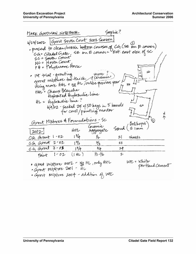
Gordion Excavation Project Architectural Conservation University of Pennsylvania Summer 2006
University of Pennsylvania Citadel Gate Field Report 132

Gordion Excavation Project Architectural Conservation University of Pennsylvania Summer 2006
University of Pennsylvania Citadel Gate Field Report 133

Gordion Excavation Project Architectural Conservation University of Pennsylvania Summer 2006
University of Pennsylvania Citadel Gate Field Report 134
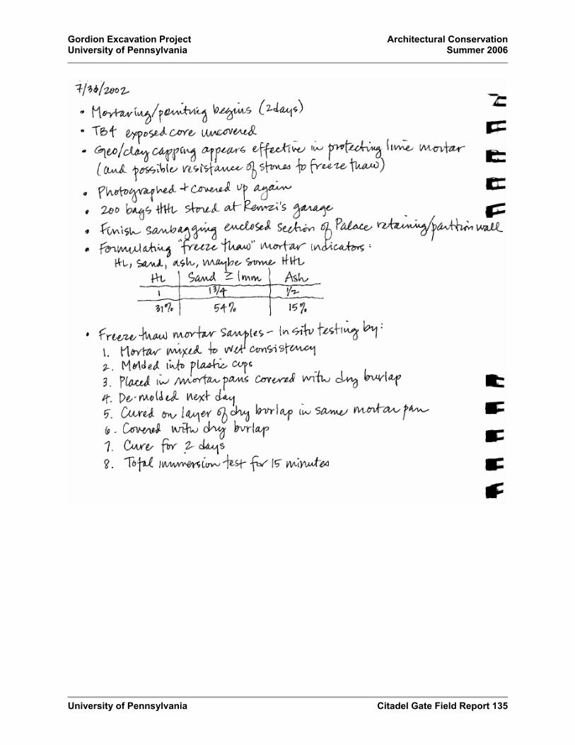
Gordion Excavation Project Architectural Conservation University of Pennsylvania Summer 2006
University of Pennsylvania Citadel Gate Field Report 135

Gordion Excavation Project Architectural Conservation University of Pennsylvania Summer 2006
University of Pennsylvania Citadel Gate Field Report 136
Masons’ Addresses

Gordion Excavation Project Architectural Conservation University of Pennsylvania Summer 2006
University of Pennsylvania Citadel Gate Field Report 137

Gordion Excavation Project Architectural Conservation University of Pennsylvania Summer 2006
University of Pennsylvania Citadel Gate Field Report 138

Gordion Excavation Project Architectural Conservation University of Pennsylvania Summer 2006
University of Pennsylvania Citadel Gate Field Report 139

Gordion Excavation Project Architectural Conservation University of Pennsylvania Summer 2006
University of Pennsylvania Citadel Gate Field Report 140

Gordion Excavation Project Architectural Conservation University of Pennsylvania Summer 2006
University of Pennsylvania Citadel Gate Field Report 141

Gordion Excavation Project Architectural Conservation University of Pennsylvania Summer 2006
University of Pennsylvania Citadel Gate Field Report 142

Gordion Excavation Project Architectural Conservation University of Pennsylvania Summer 2006
University of Pennsylvania Citadel Gate Field Report 143

Gordion Excavation Project Architectural Conservation University of Pennsylvania Summer 2006
University of Pennsylvania Citadel Gate Field Report 144

Gordion Excavation Project Architectural Conservation University of Pennsylvania Summer 2006
University of Pennsylvania Citadel Gate Field Report 145

Gordion Excavation Project Architectural Conservation University of Pennsylvania Summer 2006
University of Pennsylvania Citadel Gate Field Report 146

Gordion Excavation Project Architectural Conservation University of Pennsylvania Summer 2006
University of Pennsylvania Citadel Gate Field Report 147

Gordion Excavation Project Architectural Conservation University of Pennsylvania Summer 2006
University of Pennsylvania Citadel Gate Field Report 148

Gordion Excavation Project Architectural Conservation University of Pennsylvania Summer 2006
University of Pennsylvania Citadel Gate Field Report 149

Gordion Excavation Project Architectural Conservation University of Pennsylvania Summer 2006
University of Pennsylvania Citadel Gate Field Report 150

Gordion Excavation Project Architectural Conservation University of Pennsylvania Summer 2006
University of Pennsylvania Citadel Gate Field Report 151

Gordion Excavation Project Architectural Conservation University of Pennsylvania Summer 2006
University of Pennsylvania Citadel Gate Field Report 152

Gordion Excavation Project Architectural Conservation University of Pennsylvania Summer 2006
University of Pennsylvania Citadel Gate Field Report 153

Gordion Excavation Project Architectural Conservation University of Pennsylvania Summer 2006
University of Pennsylvania Citadel Gate Field Report 154

Gordion Excavation Project Architectural Conservation University of Pennsylvania Summer 2006
University of Pennsylvania Citadel Gate Field Report 155

Gordion Excavation Project Architectural Conservation University of Pennsylvania Summer 2006
University of Pennsylvania Citadel Gate Field Report 156

Gordion Excavation Project Architectural Conservation University of Pennsylvania Summer 2006
University of Pennsylvania Citadel Gate Field Report 157

Gordion Excavation Project Architectural Conservation University of Pennsylvania Summer 2006
University of Pennsylvania Citadel Gate Field Report 158

Gordion Excavation Project Architectural Conservation University of Pennsylvania Summer 2006
University of Pennsylvania Citadel Gate Field Report 159

Gordion Excavation Project Architectural Conservation University of Pennsylvania Summer 2006
University of Pennsylvania Citadel Gate Field Report 160

Gordion Excavation Project Architectural Conservation University of Pennsylvania Summer 2006
University of Pennsylvania Citadel Gate Field Report 161

Gordion Excavation Project Architectural Conservation University of Pennsylvania Summer 2006
University of Pennsylvania Citadel Gate Field Report 162

Gordion Excavation Project Architectural Conservation University of Pennsylvania Summer 2006
University of Pennsylvania Citadel Gate Field Report 163