e' PHASE DIAGRAMS OF THE TITANIUM-ALUMINUM, TITANIUM.CHROMIUM-IRON… · 33 Partial Phase Diagram...
96
...... .761 / WADC TECHNICAL REPORT 52-16 &??R 07,= F CS PUBL IC RELFEASEZ, LIO IST!IBUT'IOINU•I.IJ•D. WPAFS, 0. I e'" PHASE DIAGRAMS OF THE TITANIUM-ALUMINUM, TITANIUM.CHROMIUM-IRON, "AND TITANIUM-OXYGEN ALLOY SYSTEMS R. J. VAN THYNE E. S. BUMPS H. D. KESSLER M. HANSEN ARMOUR RESEARCH FOUNDATION ILLINOIS INSTITUTE OF TECHNOLOGY S/7 DECEMBER 1952 WRIGHT AIR DEVELOPMENT CENTER Reproduced From Best Available Copy
Transcript of e' PHASE DIAGRAMS OF THE TITANIUM-ALUMINUM, TITANIUM.CHROMIUM-IRON… · 33 Partial Phase Diagram...

...... .761 /
WADC TECHNICAL REPORT 52-16
&??R 07,= F CS PUBL IC RELFEASEZ,
LIO IST!IBUT'IOINU•I.IJ•D.
WPAFS, 0.
I e'" PHASE DIAGRAMS OF THE TITANIUM-ALUMINUM, TITANIUM.CHROMIUM-IRON,"AND TITANIUM-OXYGEN ALLOY SYSTEMS
R. J. VAN THYNEE. S. BUMPS
H. D. KESSLER
M. HANSEN
ARMOUR RESEARCH FOUNDATION
ILLINOIS INSTITUTE OF TECHNOLOGY
S/7
DECEMBER 1952
WRIGHT AIR DEVELOPMENT CENTER
Reproduced From
Best Available Copy
NOTICES
When Government drawings, specifications, or other data are usedfor any purpose other than in connection with a definitely related Govern-ment procurement operation, the United States Government thereby in-curs no responsibility nor any obligation whatsoever; and the fact thatthe Government may have formulated, furnished, or in any way suppliedthe said drawings, specifications, or other data, is not to be regardedby implication or otherwise as in any manner licensing the holder orany other person or corporation,or conveying any rights or permissionto manufacture, use, or sell any patented invention that may in anywaybe related thereto.
The information furnished herewith is made available for studyupon the understanding that the Government's proprietary interests inand relating thereto shall not be impaired. It is desired that the JudgeAdvocate (WCJ), Wright Air Development Center, Wright-PattersonAir Force Base, Ohio, be promptly notified of any apparent conflict be-tween the Government's proprietary interests and those of others.

WADC TECHNICAL REPORT 52-16
PHASE DIAGRAMS OF THE TITANIUM-ALUMINUM, TITANIUM-CHROMIUM-IRON,AND TITANIUM-OXYGEN ALLOY SYSTEMS
R. J. Van TbyneE. S. Bumps
H. D. Kessler
M. Hansen
Armour Research FoundationIllinois Institute of Technology
December 1952
Materials LaboratoryContract No. AF 33(038)-8708
/ RDO No. 615-11
Wright Air Development CenterAir Research and Development Command
United States Air ForceWright-Patterson Air Force Base, Ohio
McGregor & Werner, Dayton, Ohio250 - February, 1953

FOR7DWORD
The binary equilibrium diagrams of titanium and its alloyingelements can be considered as an absolute prerequisite for the under-standing of the behavior of all titanium base alloys.
In the course of the alloy development work, which the MaterialsLaboratory has been sponsoring for several years at Battelle MemorialInstitute, the first preliminary knowledge of the phase relationshipsat the titanium-rich end of various alloy systems was obtained. Thisinvestigation has also furnished a broader knowledge of the applicabilityof the different alloying elements to the production of practicaltitanium alloys.
In view of the aforementioned necessity for a knowledge of thebinary enuilibrium diagrams, and thepaucityof information on thissubject in the literature, it was decided to start a broader researchproject on binary diagrams of titanium and the most promising alloyingelements. Investigation was started on ten alloy systems, the workbeing divided among five research institutions. More recently, addi-tional binary and ternary systems were included in this program.
After the first year of research, a summary report was preperedby each contractor and these reports are being published as Air ForceTechnical Reports. The following list gives a compilation of the con-tractors, systems investigated, and technical report numbers concerned.Since, in some cases, the investigations are not yet finished, thereports concerned are designated as Part 1. Part 2 will follow assoon as the investigations are completed, and will disclose the finalshape of the equilibrium diagrams.
Contractor Systems Investigated Report No.
Armour Research Foundation Ti-Si, Ti-Cb, Ti-Mo AFTR 6225Ti-O, Ti-Al, Ti-Fe-Cr WADC TR 52-16
Battelle Memorial Institute Ti-Mn, Ti-Ta, Ti-W AFTR 6516 Pt 1
Massachusetts Institute of Technology Ti-Cr, Ti-Cu AFTR 6595 Pt 1AFTR 6595 Pt 2
Ti-Cr-O WADC TR 52-255
New York University Ti-Ni AFTR 6569 Pt 1AFTR 6569 Pt 2
University of Notre Dame Ti-Fe AFTR 6597 Pt 1AFTR 6597 Pt 2
This report was Irepared by the Armour Research Foundation,Chicago, Illinois, under USAF Contract No. AF 33(039)-97O. Thecontract was initiated under Research and Development Order No. 615-11,"Titanium Metal and Alloys" and was administered under the directionof the Materials Laboratory, Directorate of Research, Wright AirDevelopnent Center, with Lt W. R. Freeman, Jr., acting as projectengineer.
WADC TR 52-16

ABSTRACT
Partial phase diagrams are presented for the systems titanium-aluminum, titanium-chromium, titanium-iron, titanium-chromium-iron, andtitanium-oxygen. All studies are completed except for the titanium-chromium-iron system, which requires further confirmatory work in certainareas. The results are outlined in Section IV of this report (page 78).
PUBLICATION REVIEW
This report has been reviewed and is approved.
FOR T21 COMMANDING G7TNRRAL:
M*•, SORTZ
Colonel, USAFChief, Materials LaboratoryDirectorate of Research
WADC TR 52-16

TABLE OF CONTENTSPage
I. INTRODUCTION .............. ...................... .i.. 1II. EXPERIMENTAL PROCEDURE .................. 1
A. Materials ............... . .. . . . .i....1
B. Analytical-Methods ........... ................... 31. Aluminum .................... ......... 32. Iron . ......... ............. 33. Chromium . . . .................... 34. oxygen ...... ....................... 3
III. RESULTS AND DISCUSSION ... .............. . 4A. The Titanium-Aluminum System ......... ............. 4
1. Experimental procedure ..... ............... 42. Results and Discussion . ........ 0 . . . 7
a. Structural characteristics . . . .. .. 7
b. X-ray diffraction results ......... 15C. Melting range determinations ............ 19d. Hardness test results ........... 19
B. The Titanium-Chromium-Iron System ......... . 22
1. The Titanium-Chromium and Titanium-Iron Systems . 22a. Experimental procedure . . .......... 22
b. Results and discussion ............... . . 23(1) The system titanium-chromium . . . .. 23
(a) Netallographic studies . . . . 24(b) Melting range determinations . . . 30
(2) The system titanium-iron ........... 31(a) Metallographic studies ..... 32(b) X-ray studies .......... 35(c) Melting range determinations . 37
(3) Hardness of titanium-chromium andtitanium-iron alloys .. ......... .. 39
2. The Titanium-Chromium-Iron System .......... .. 41a. Experimental procedure ... .......... ... 41b. The space model .o e... ............... 42c. Isothermal sections ............ . 44d. Microstructure ............... 54e. Hardness ........... .................... 54
C. The Titanium-Oxygen System . . . ............. 591. Experimental procedure .......... ...... 61
a. Preparation of alloys ... ........... .. 61'b. Annealing treatments ............. 62
2. Discussion of results ....... ................ 63a. The phase diagram .......... ............. 63
b. Structural characteristics ........... .. 65c. Melting range determinations .. ........ .. 73d. X-ray diffraction studies .. .......... 74e. Hardness determinations ... .......... .. 76
IV. SUMMARY OF RESULTS ............ ................... ... 80A. The Titanium-Aluminum System . . . . . .......... 80B. The Titanium-Chromium System .... ............. ..... 80C. The Titanium-Iron System ..... ............... ... 80
WADC TR 52-16 iv

Page
D. The Titanium-Chromium-Iron System ............. - 81E. The Titanium-Oxygen System . ......... ... 81
V. FUTURE WORK ..... .......... . ............. 81'V. CONTRIBUTING PERSONNEL ......................... .. 82VII. LOGBOOKS ......................... ........... 82BIBLIOGRAPHY .. .......... . . .............. 83APPENDIX I A Theoretical Analysis of the Structure of TiO . . . 85
LIST OF ILLUSTRATIONS
Figure Page
1 Partial Diagram of the Titanium-Aluminum System 82 The Titanium-Aluminum Phase Diagram 93 23% nominal aluminum alloy water quenched after annealing 2
hours at 1250°C 104 7% aluminum alloy pressed 70% and water quenched after 50 hours
at 1000°C 105 25% aluminum alloy quenched after 6 hours at 1200oC 106 8% aluminum alloy pressed 35% and water quenched after 24 hours
at 1OOO C 107 25% aluminum alloy water quenched after 24 hours at 10000C 118 25% aluminum alloy water quenched after 120 hours at 850°C 119 27.3% aluminum alloy water quenched after 180 hours at 8000C 1120 30% aluminum alloy water quenched after 24 hours at 1000 C 1111 34% aluminum alloy water quenched after 6 hours at 12000C 1212 32% aluminum alloy water quenched after 1/2 hour at 13500C 1213 36% aluminum alloy, pressed 25% and water quenched after 24
hours at l0OOC 1214 49% aluminum alloy homogenized at 12000C, furnace cooled and
water quenched after 48 hours at 1OO0C 1215 56% aluminum alloy treated as in Fig. 14 1316 61% aluminum alloy water quenched after 24 hours at 10000C 1317 61% aluminum alloy, as cast 1318 62% aluminum alloy, as cast 1319 64% aluminum alloy, as cast 1420 Lattice Parameter-Composition Curves for Alpha Solid Solution
Titanium-Aluminum Alloys 1721 Lattice Parameter-Composition Curves for Gamma Solid Solution
Titanium-Aluminum Alloys 1822 Melting Ranges for the Titanium-Aluminum System 2023 Comparative Vickers Hardness-Composition Curves for Titanium-
Aluminum Alloys Treated as Indicated 2124 The Constitutional Diagram of the Titanium-Chromium System as
Determined by McQuillan 2525 Partial Phase Diagram of the Titanium-Chromium System. Insert
Shows Section of Diagram Duplicated with Iodide Titanium-Base Alloys 26
WADC-TR-52-16 v

Figure Page
26 18% chromium alloy, homogenized, annealed at 675*C for 360hours 28
27 8% chromium alloy, homogenized, annealed at 6500C for 305 hours 2828 Same alloy as Fig. 27, homogenized, annealed at 7000C for 190
hours 2829 50% chromium alloy, arc melted and chill cast 2930 48% chromium alloy, slowly cooled in a graphite crucible 2931 66% chromium alloy, annealed at 13850C for 20 minutes and water
quenched 2932 Same alloy as Fig. 31, annealed at 1260 0 C for 2 hours and water
quenched 2933 Partial Phase Diagram of the Titanium-Iron System 33
34 18% iron alloy, homogenized and water quenched after anneal-
ing at 550C0 for 740 hours 3435 Same alloy as Fig. 34, but at higher magnification 3436 13% iron alloy treated the same as the 18% alloy (Fig. 34) 3437 54% iron alloy, homogenized, annealed at 9000C for 72 hours
and water quenched, 3638 36% iron alloy, held at 110500 20 minutes, and slowly cooled
in a graphite crucible 3639 14% iron alloy, homogenized and water quenched after annealing
at 120000 for 15 minutes 3840 16% iron alloy treated the same as the 14% alloy (Fig. 39) 3841 20% iron alloy treated the same as the 14% alloy (Fig. 39) 3842 22% iron alloy treated the same as the previous alloys 3843 Vickers Hardness vs Composition for Chromium and Iron
Titanium-Base Alloys 4044 Space Model of the Solid State Reactions in the System
Titanium-Chromium-Iron 4345 Partial Isothermal Section at 9000C of the System Titanium-
Chromium-Iron 4546 Partial Isothermal Section at 8000C of the System Titanium-
Chromium-Iron 46
47 Partial Isothermal Section at 750°C of the System Titanium-Chromium-Iron 47
48 Partial Isothermal Section at 7000C of the System Titanium-Chromium-Iron 48
49 Partial Isothermal Section at 650°C of the System Titanium-Chromium-Iron 49
50 Partial Isothermal Section at 6000C of the System Titanium-Chromium-Iron 50
51 Partial Isothermal Section at 5500C of the System Titanium-Chromium-Iron 51
52 Isotherms of the Lower Surfaces of the Beta Phase Space inthe System Titanium-Chromium-Iron 52
53 2% iron, 2% chromium alloy annealed at 9000C for 72 hours andwater quenched 55
WADC TR 52-16 vi

Figure Page
54 2% iron, 3% chromium alloy homogenized, annealed at 9OO'C for
72 hours and water quenched 5555 0.5% iron, 0.5% chromium alloy, water quenched after annealing
at 650°C for 432 hours 5656 10% iron, 4% chromium alloy homogenized, annealed at 6500C
for 432 hours 5657 2% iron, 12% chromium alloy homogenized, annealed at 650*C
for 432-hours 5658 18% iron, 4% chromium alloy homogenized, annealed at 650°C
for 432 hours and water quenched 5759 8% iron, 16% chromium alloy, homogenized, annealed at 650°C
for 432 hours and water quenched 5760 Vickers Hardness of Titanium-Chromium-Iron Alloys (Iron-
Chromium Ratio = 1:1) 5861 Phases and Phase Ranges in the System Titanium-Oxygen
(Ehrlich) 60
62 Partial Phase Diagram of the Titanium-Oxygen System 6463 Titanium Rich Portion of the Titanium-Oxygen System 6664 0.2% oxygen alloy quenched after 48 hours at 9500C 6765 1.0% oxygen alloy quenched after 4 hours at 12000C 6766 0.8% oxygen alloy quenched from 17000C 6767 1.0% oxygen alloy quenched after 24 hours at 1OO00 C 6768 2.0% oxygen alloy quenched after 24 hours at 1OO0 C 6869 3.0% oxygen alloy quenched from 17000C 6870 12% oxygen alloy quenched after 4 hours at 12000C 6871 12% oxygen alloy quenched from 18500C 6872 15% oxygen alloy quenched after 4 hours at 12000C 6973 17% oxygen alloy quenched after 4 hours at 1200°C 6974 17% oxygen alloy quenched frota 17000C 6975 17% oxygen alloy quenched after 2 hours at 14000 C 6976 19% oxygen alloy quenched after 4 hours at 12000C 7077 18% oxygen alloy quenched after 120 hours at 8000C 7078 20% oxygen alloy quenched after 500 hours at 8000C 7079 22% oxygen alloy quenched after 120 hours at 8000C 7080 29% oxygen alloy quenched after 4 hours at 12000C 7181 Lattice Parameter-Composition Curves for the Alpha Phase in
Titanium-Oxygen Alloys 7582 Lattice Parameter-Composition Curves for the TiO Solid Solu-
tion Titanium-Oxygen Alloys 7783 Vickers Diamond Pyramid Hardness vs Oxygen Content 79
WADC TR 52-16 vii

LIST OF TABLES
Page
I Nominal Compositions vs Chemical Analysis for Typical
Titanium-Aluminum Alloys 5
II Annealing Conditions for Titanium-Aluminum Alloys 6
III Lattice Parameters of the Alpha Titanium-Aluminum Phase 16
IV Lattice Parameters of the Garmia Titanium-Aluminum Phase 16
V Typical Correlation Between Nominal Composition andChemical Analysis for Titanium-Chromium and Titanium-IronAlloys 23
VI Melting Range Determinations for Titanium-ChromiumAlloys 31
VII Comparison of Interplanar Spacings for Ti4Fe20 andTi 2 Fe Reported Elsewhnere 37
VIII Melting Range Determinations 39
IX Annealing Conditions for Titanium-Chromium-Iron Alloys 41
X Chemical Analysis of As-Cast Titanium-Oxygen Alloys 61
XI Appearance of Titanium-Oxygen Alloy Ingots 62
XII Annealing Conditions for Titanium-Oxygen Alloys 63
XIII Melting Temperatures of Iodide Titanium-Oxygen Alloys 7h
XIV Summary of Observed and Calculated Data on theDelta Phase 78
WPDM TR-52 16 viii

PHASE DIAGRAMS OF THE TITANIUM-ALUMINUM,
TITANIUM-CHROMIUM-IRON, AND TITANIUM-OXYGEN ALLOY SYSTEMS
I. INTRODUCTION
This is a Summary Report of the second year's work on the extensionof Contract No. AF 33(038)-8708. The object of the extension was thedetermination of phase diagrams of the systems titanium-aluminum, titanium-chromium-iron, and titanium-oxygen.
Micrographic analysis of annealed arc melted alloys was the principalmethod used for the determination of the subject systems. Thermal analy-sis, incipient melting studies, and X-ray diffraction analysis were alsoused to obtain data on certain portions of the systems.
II. EXPERIMENTAL PROCEDURE
The alloys were prepared by arc melting on a copper block in a heliumatmosphere, using a water-cooled tungsten electrode. As this method wasdetailed in the Final Report of last year's work*, no further descriptionneed be given here. Where somewhat special techniques were used, theyare presented in the section of this report where they apply.
Sample preparation methods, annealing procedures, incipient meltingand thermal analysis techniques, metallographic procedures, and X-raydiffraction methods were essentially identical to those used in lastyear's studies. Therefore, the reader is referred to the previous reportfor the procedural details. Variations in the techniques were requiredin some cases; these changes are presented in the appropriate sectionsof this report.
A. Materials
Iodide titanium obtained from the New Jersey Zinc Company throughWight Air Development Center was used for the preparation of most of thealloys. This metal had a purity of 99.9+% with minor quantities of Fe,Al, Mn, Mg, Si, 0, and N.
A special lot of high purity magnesium reduced sponge titanium wasused to prepare a limited number of alloys for the titanium-chromium andtitanium-iron binary studies. This material had an as-cast hardness of105 DPN and the analysis was as follows:
*Air Force Technical Report No. 6225
WADC-TR-52-16 1

Iron 0.02%Magnesium 0.045Silicon 0.005Nickel 0.003Chlorine 0.06
The aluminum was obtained from the Aluminum Company of America inthe form of sheet. The given analysis was:
Silicon 0.0006%Iron 0.0005Copper 0.0022Magnesium 0.0003Calcium <0.0006Sodium <0.0005Aluminum 99.99
Vacuum melted iron and chromium were purchased from the National Re-search Corporation. The impurities in the iron were:
Silicon 0.0093%
Nickel 0.012Phosphorus 0.0023Sulfur 0.013Carbon 0.011
Two heats of chromium were used for these studies; Heat No. 591 forthe titanium-chromium system, and No. 590 for the titanium-chromium-ironsystem:
Impurity Heat No. 591 Heat No. 590
Carbon 0.102% 0.015%Oxygen 0.019 0.066Nitrogen 0.0017 0.0022
High purity titanium dioxide purchased from the National Lead Companywas used in the preparation of the arc melted titanium-oxygen alloys.The spectrographic analysis of this material is as follows:
SiO2 0.07% Pb <0.002%
Fe 2 0 3 0.002 Mn <0.00005
A1203 <0.001 W <0.01
Sb2 03 <0.002 V -0.002
SnO3 <0.001 Cr <0.002
Mg 0.001 Ni <0.001
Nb <0.01 Mo <0.002
Cu 0.0004
WADC TR 52-16 2
B. Analytical Methods
As weight losses during melting were of minor proportions for allsystems studied, nominal compositions were used in plotting the data.To further substantiate the use of nominal values, chemical analysis wasapplied to a limited number of representative alloys in each system. Theanalytical methods used for the titanium alloys are summarized below:
1. Aluminum
Dissolve appropriate sample in 1-3 H2SO4;
Dilute so that H2SO4 concentraticn is 5-10%;
Separate Ti with cupferron (chloroform extraction);
Evaporate aqueous material;
Dilute, precipitate Al(OH) 3 with NHI4OH, use methyl orange indicator,filter, ignite and weigh A12 03 -
2. Iron
Dissolve appropriate sample in 1-3 H2SO4;
Dilute to 150 ml, add 5 gn tartaric acid;
Add excess ammonia and some (NH4)2SX;
Heat to coagulate FeS;
Filter off FeS and wash well with hot water;
Return filter to original beaker;
Dissolve in HNO3 .H2SO4, remove all NO3 by fuming, dilute to 150 ml;
Reduce by usual procedures (ZnCl 2 , PbC1 2 , SnC12);
Titrate iron with standard K2Cr 20 7 or KMnOh4.
3. Chromium
Dissolve sample in 1-3 H2SO4;
Dilute to 200 ml, heat to boiling;
Add AgNO3 and oxidize chromium with (NH4)2S208;
Precipitate AgNO3 with dilute HC1, boil to coagulate;
Cool and add excess of standard ferrous ammonia sulfate;
Titrate with standard K2 Cr20 7 or KMnOh4.
(This method is essentially the same as is used in all ferrous lab-oratories.)
4. Oxygen
The liquid amalgam reduction method developed by the National Lead
Company was used. It is briefly as follows:
WADC TR 52-16 3

Dissolve sample in H2 SO4-(NH 4 )2 SO4 ;
Dilute to 150 ml, cool, and transfer to separating funnel;
- Add liquid zinc-amalgam;
After 5 min of shaking, add 5 ml CC14, draw off amalgam;
Titrate with standard KMnO 4 to faint pink.
III. RESULTS AND DISCUSSION
A. The Titanium-Aluminum System
Included in the available information concerning the phase relation-ships in titanium-rich titanium-aluminum alloys is a brief statement byBrown (1) that "aluminum raises the transformation temperature to 1000'C(1832 0F)". This observation is interesting in that it is the first exampleof a metallic alloying component raising the transformation temperatureof titanium, and consequently widening the field of the alpha solid solu-tion. Busch and Freyer (2) presented resistivity data which indicatedthe formation of titanium-rich solid solutions of 1 and 3% aluminum alloysprepared by powder metallurgy methods.
Duwez (3) found only one other intermediate phase besides the knowncompound TiAl 3 (62.7% Al). This phase, designated as gamma, is of vari-able composition; its crystal structure is of the AuCu type and istherefore based on the composition TiAl (36.02% Al).
Earlier work on the constitution of the aluminum-rich alloys hasbeen reviewed by Hansen (4), and need not be discussed here. The tetra-gonal crystal lattice of TiAl , as found by Fink, Van Horn and Budge(5), was confirmed by Brauer •6). Recently, Schubert (7) has reportedthat TiA1 3 is homogeneous within a limited composition range; however,the solubility limits were not given.
The titanium-aluminum phase diagram as presented in this report wasdetermined by micrographic analysis of alloys containing from 1 to 62%aluminum, annealed at and quenched from temperatures between 700Q and14000C. The phases and phase ranges investigated extend to the compoundTiA13 (62.7% Al) to join the aluminum-rich end of the system determinedby other investigators, thus completing the diagram.
1. Experimental procedure
All ingots were carefully weighed after arc melting, to detect pos-sible losses. Comparison of weight before and after melting showed noappreciable weight changes. Also, chemical analyses were in close agree-ment with nominal compositions (Table I). The diagram as presented is,
WADO-TR-52-16 4
therefore, based on nominal compositions. Alloys were prepared having thefollowing nominal aluminum contents: 1 . . . 36 (1% increments), 38, 40,41, 42.5, 44, 45, 46, 47.5, 49 . . . 64 (1% increments), 67, 70, 80, and90.
TABLE I
NOMINAL COMPOSITIONS VS CHEMICAL ANALYSIS
FOR TYPICAL TITANIUM-ALUMINUM ALLOYS
Nominal Composition, % Al Chemical Analysis, % Al
16.0 15.84
27.3 27.08
36.0 35.89
45.0 44.9653.0 53.16
62.7 62.97
Ingots with up to 14% aluminum were cold pressed various amounts inorder to increase the rate of attaining equilibrium structures on heattreatment. The amount of cold deformation that could be applied decreasedwith increasing aluminum content until alloys containing 12% or morealuminum cracked after only a few per cent deformation.
Samples annealed at temperatures of 700"-1000lC were sealed inevacuated Vycor bulbs. From 10000 to 1200*C, the samples were treatedin sealed quartz capsules under a partial pressure of argon. Above1200C, an additional precaution was taken to prevent contaminationof the samples by wrapping them in molybdenum sheet, to avoid contactbetween specimens and the quartz capsules in which they were sealedunder partial pressure of argon. The annealing times at the varioustemperatures are presented in Table II.
WOC-TR-$2-L6 5

TABLE II
ANNEALING CONDITIONS FOR TITANIUM-ALUMINUM ALIDYS
AnnealingTemperature, oC Time,Hours Prior Homogenization Treatment
700 330
800 180
800 180 1200*C - 24 hours
850 120
900 90
1000 24
1000 48 1200C - 24 hours
1050 24
1100 7
1150 6
1200 6
1250 21300 1/61350 1/6
1350 1/2
1400 1/6
The powders for X-ray diffraction patterns were obtained by filingor crushing annealed specimens. The powders thus obtained were sealedinside a capped titanim container which was, in turn, placed inside anevacuated Vycor capsule and heated to the prior annealing temperaturefor a short time. The Vycor bulbs were quenched in water, but the bulbswere not broken until the contents were cool.
Solidus data were determined by incipient melting techniques. First,.the melting temperature for a specimen of given composition was visuallyobserved. Then a series of specimens of the same composition were quenchedat temperature intervals below the observed melting, and subsequentlyexamined metallographically. The accuracy of the solidus data is of theorder of +-15C. Liquidus data were obtained from cooling curves forthree titanium-aluninum alloys.
Vickers hardness data obtained using a load of 10 or more kilogramsrevealed considerable scatter due to irregular or deformed impressions.
WADO TR 52-16 6

Fairly uniform impressions, and consequently more consistent data, were
obtained with a 2 1/2 kilogram load.
2. Results and Discussion
The essential features of the phase diagram presented in Figs. 1 and2 are two peritectic reactions, P + melt y i, and y + melt •-' TiAl 3 ,at about 14600 and 1340°C, respectively; and one peritectoid reaction,
S+ y Z a, at 1240 °C. The temperature of the polymorphic transforma-tion of titanium is raised by addition of 29% aluminum from 885@ to 1240@C,giving rise to extended ranges of alpha and beta solid solutions. Thesolubility of aluminum in alpha titanium is approximately 24.5% at 9000C,and increases to 31% aluminum at 12400C. The intermediate phase, gamma,is homogeneous over a range of composition from about 37 to 60% aluminumat the solidus temperature, and from 35.5 to 44.5% at 800°C. The phaserelationships for the alloys higher in aluminum content than the compoundTiAl 3 (62.7% Al), which are included in Fig. 2, are based on earlier work(5).
a. Structural characteristics
Microstructures of alloys quenched from the various phase fieldsare shown in Figs. 3-19.
Specimens quenched from the beta field of the diagram revealed atransformation of beta to serrated alpha (Fig. 3). The duplex structureof specimens quenched from the narrow a + P field is shown in Figs. 4and 5. Alloys quenched from the alpha phase field were characterizedby equiaxed grains of alpha solid solution (Figs. 6 and 7).
The first trace of gamma appears as a precipitate of small particlesalong parallel striations in the alpha grains (Fig. 8). At slightlyhigher aluminum contents, in the temperature range 7000-10000C, gammaprecipitates from the alpha solid solution in a lamellar fashion. Thisprecipitate appears to have nucleated at the grain boundaries and sub-sequently grown into the striated alpha grains (Fig. 9). The amount ofthe lamellar structure varies from traces up to 100% (Fig. 10), dependingon the composition and time at temperature of annealing. The precipita-tion results from the large decrease in the solid solubility of aluminumin alpha titanium, varying from about 31% at 12940C to 24.5% at 800°C.Massive gamma appeared in alloys with an aluminum content greater than31% (Fig. 11).'
A typical structure of alloys quenched from the P + y field is shownin Fig. 12. As in all alloys quenched fram the beta field at this tem-perature level, the white phase appears serrated due to the transforma-tion -- a during the quench. The gamma phase has precipitated in parallelplates along the boundaries of the original beta grains.
The structure of the gamma phase at 36% aluminum is shown in Fig. 13.As depicted in Fig. 1, this phase is homogeneous over a wide range of com-position. Alloys with higher aluminum contents approaching the y/y + TiA13
WADC TR 52-16 7
ATOMIC PERCENT ALUMINUM10 20 30 40 50 60 70 80
I I I I I I'31700
'-.MELT +G _ t
1600 4
1500-
1400-0000
1300- 0 000 00 * 0 0 0 0000 0000 xxx
0 0 0 0 0000000*----D )000 0 0 00 N
wS1200 o000o000ooo00oooooo XXXI 0 000000000 oco XXXNxNxxxx
7- 1100 .0000000 00 0000 0 000 1111I11 ) 0 0 00 XXXXXXX XXXIIIw MELT
T1 Al3
1000 0'X 0 0 0 00. IXIXIxXIX 0 00000 0 N x XNIINXXIXIXxx
900 000000 000000 XX XXIxI 0 000 KXX XXIXXXX x X
00 00 00 00 0 00 N x I 0 N X x
800 0000~OO XXXXXX 0 00 0K X 1 ~XXXEXXXKXXXXI
700 oooxoooooo~ooooooooooo~oO XXIxxXXXXX 0000 0 1x XX X x x N
600 £ ___LL Al.10 20 30 40 50 60 70
WEIGHT PERCENT ALUMINUMFig. I - Partial Diagram of the TitasiumA~lumiu Syvtem
WADC -TR-52- 16 8

ATOIMIC PERCENT ALUMINUM10 20 30 40 50 60 70 80 90 100
1800 I'i I'1 I' 3200
1700 - N.30"N • MELT -1", -3000
1600 >,/M L MELT _
14600 2800
1400- 137 1340 260034.64
60 2400 .oo 1300 12400 0
S29 34.5 w
• 1200-. 31 2200
100a a7y +TiAI 3 MELT + TiAI3 10
885o 1600
800 -
1400
700 I I'I 6600C600 A1200
600 24.5 35.5 44.5 TiAI 3 +AII I 1-1000I I I
I I I I i I i I I I I I
0 10 20 30 40 50 60 70 80 90 100WEIGHT PERCENT ALUMINUM
Fig. 2 - The Titanium-Aluninum Phase Dinm-
WADC-TR-52 -16 9

f -
-7 - x_ .. - ..
Neg. No. 3725 X250 Neg. No. 3410 X250
Fig. 3 Fig.L423% nominal alum inum alloy water 7% aluminu alloy pressed 70% andquenched after annealing 2 hours at water quenched after 50 hours at1250*C. Typical serrated a transfor- 10000C. The structure showTs a mix-mation structure of alloys quenched ture of isothermal a plus trans-from the 3 phase field. formed • (dark).
Neg. No. 3402 X150 Neg. No. 3340 X250
Fig. 5 Fig. 625% aluminum alloy water quenched 8% aluminum alloy pressed 35% andafter 6 hours at 120000. Structure water quenched after 24 hours atshows a plus transformed 10. l00'C. Large equiaxed grains of a
titanium.
Etchant: 2% HF, 3% HNO3 in water
WADC TR 52-16 10

Fi 7/ Fi. 8
25% alumninwa alloy water quenched 25% aluminum alloy water quenchedafter 24 hours at IO000*C. Large after 120 hours at 850°C. Structureequiaxed. grains of a titanium. shows traces of TiA1 precipitated
along parallel planes in a grains.
Neg. No. 3413 X150 Neg. No. 3415 X800
Fig. 9 Fig. 1027.3% aluminum alloy water quenched 30% aluminum alloy water quenchedafter 180 hours at 8000C. Structure after 24 hours at lO000*C. Fineshows nucleation and growtoh of a lamellar structure of Tiil and alamellar precipitate of TiA1 in a. titanium.Note the striations in the a grains.
Etchant: 2% HF, 3% HN03 in water
HADC TR 52-16 11

Neg. 1o. 3404 X250 Neg. No. 3641 X2002%HF-,3%HN0 3 in water 60glycerine, 20HN0 3 , 20HF
Fig. 11 Fig. 1234% aluminum alloy water quenched 32% aluminum alloy water quenchedafter 6 hours at 12000 C. Structure after 1/2 hour at 135OoC. Serratedshows the last traces of a in TiAl a grain structure with y phase char-matrix. acteristic of alloys quenched from
the j + y phase region of the diagram
*'c.
Neg. No. 3409 X150 Neg. No. 3642 X800Polarized light Unetched 60 glycerine,20HN0 3 ,20HF
Fig. 13 Fig. 1436% aluminum alloy, pressed 25% and 49/ aluminum alloy homogenized atwater quenched after 24 hours at 1200 0C, furnace cooled and water1000lC. Equiaxed grains of y phase quenched after 48 hours at 10000C.as revealed by polarized light. Structure shows a 'Jidmannstfitten
pattern of TiAI 3 platelets pre-cipitated in a y matrix.
WADC-TR-52-16 12

Neg. N~o. 3643 XBOO Neg. No. 3346 X25060 glycerine, 20HN03 20HF 60 glycerine, 20HN03 , 2OHF
Fig. 15 Fig. 16561 aluminum alloy treated as in Fig. 61i" aliuminum alloy water quenchedlh.- Structure shows 'idinannst'atten after 24 hours at 1000*C. Structurepattern of TiAl 3 precipitate plus shows large primary plates of yrmassive globules of TiAl 3 in a yphase plus Widmannst'atten plateletsmatrix. of precipitated y in TiAl 3 matrix.
N~eg. No. 3490 XlO0 Neg. No. 3491 X20P:olarized light Unetched 60 glycerine,20HNO 3,20HF
Fig. 17 Fig. 1861% aluminum, alloy, as cast. Struc- 62%1 aluminum alloy, as cast. Struc-ture shows primary plates of y in a ture shows further evidence of aTi-Al 3 matrix, giving evidence that peritectic reaction. MicrographTiAl 3- was formed by a peritectic shows two y plates surrounded byreaction. peritectically formed TiAl which,
in turn, is surrounded by low melt-ing aluminuma in the interstices.
qADC-TR-52-16 13

Neg. No. 3644 X25060 glycerine, 20HNO3 , 20HF
Fig. 1964% aluminum alloy, as cast. Struc-ture shows primary TiAl 3 surroundedby aluminum in the grain interstices.
WADC TR 52-16 14

boundary become increasingly brittle and contain many cracks, but thestructure of these alloys after annealing treatments shows the sameresponse to polarized light as does the 36% aluminum alloy of Fig. 13.In the as-cast condition, these alloys were cored. Although homogeniza-tion anneals for as long as 24 hours at 12000C almost completely eliminatedcoring, traces of residual inhomogeneity within the grains caused somedifficulty in accurately locating the y/y + TiAl3 boundary. Longerhomogenization times could possibly have eliminaled this small amountof residual coring; however, longer exposure times at these high tempera-tures were considered impractical. The resulting scatter in data limitsthe accuracy of locating the Y/Y + TiA13 boundary to about t1%.
Figure 14 illustrates the structure of a homogenized 49% aluminumalloy quenched after 48 hours at 10000C, and shows a Widmannstatten pat-tern of TiAl 3 platelets, which precipitated from the saturated gammaphase. Given the same treatment, alloys containing 56-59% aluminumrevealed a similar Widmannstitten precipitation of TiAI 3 in a gamma matrixwith the addition of massive TiAl 3 globules (Fig. 15). The latter wereapparently formed by the peritectic reaction y + melt -4- TiAlI, due tothe rapid solidification of the ingot, and were not fully absorbed bythe gamma phase during the subsequent homogenization anneal.
Figure 16 illustrates the structure of a 61% aluminum alloy quenchedfrom 1000C0, and shows primary plate-like crystals of the gamma phase ina matrix of TiAl The Widmannst~tten pattern in the TiA13 matrix devel-oped during the .nneal, and represents gamma platelets precipitated fromthe saturated TiAl 3 phase. This proves that TiAl3 has a certain homo-geneity range which becomes narrower with fall in'temperature. The extentof this range was not determined, because this subject is beyond the scopeof the investigation. Since no detailed information on the homogeneityrange of this compound is available, the TiAl 3 phase in Fig. 1 was arbi-trarily indicated as a vertical line. The fact that TiA13 is homogeneouswithin a limited composition range has been reported recently by Schubert(7) without giving the solubility limits.
The TiA13 phase, previously reported (5) to have a maximum meltingpoint, is formed by the peritectic reaction Melt + y-- TiA1 3 . Evidenceof this is given in the as-cast structure of alloys with 61 and 62%aluminum (Figs. 17 and 18). Figure 18 exhibits primary gamma platessurrounded by peritectically formed TiAl 3 , idich in turn is surroundedby the low melting aluminum phase seen in the fine interstices of theTiA13 crystals. The positive identification of the gamma and TiAl 3phases was aided by their highly different characteristics when examinedunder polarized light. At aluminum contents higher than that of theTiAl 3 phase, the structure, as shown in Fig. 19, reveals primary TiAI 3phase surrounded by low melting aluminum.
b. X-ray diffraction results
X-ray diffraction studies were made on a series of alpha solid solu-tion alloys and also a series of single phase gamma alloys, to determinethe lattice parameters and the solubility limits of aluminum in the alphaand gamma phases. It was also desired to determine whether the beta to
WADC TR 52-16 15

alpha transformation on quenching alloys from the beta field could be sup-pressed.
A summary of the lattice parameter measurements for the alpha phaseis given in Table III. A graphic presentation of the effect of aluminumadditions on the parameters of the hexagonal close packed lattice, asshown in Fig. 20, reveals the very pronounced effect of initial additionsof aluminum on the dimensions of the titanium lattice. Near the solubilitylimit, the curves appear to flatten off greatly. The markedly reducedslope of the parameter curves makes a parametric determination of thealpha solubility limit impractical. The X-ray results also confirmedthe metallographic observation that the beta phase is not retained byrapid quenching.
The crystal structure of the gamma phase between 38 and 55 weightper cent aluminum is ordered face centered tetragonal, with an axialratio close to unity. A summary of the lattice parameter measurementsis presented in Table IV, and a graphic representation appears in Fig. 21.The lattice parameters are linearly dependent upon, and show increasingtetragonality with, increasing percentages of aluminum. These alloyshave been quenched from 1200*C, indicating that either the ordered struc-ture is stable to high temperatures, or the disorder -30 order transforma-tion, if any, cannot be suppressed by quenching.
TABLE III
LATTICE PARA'ETERS OF THE ALPHA TITANIUM-ALUMINUM PHASE
0 QuenchedWt.% A] At.% Al c (A) a (A) c/a from
0 0 4.679 2.943 1.591 8500C4 6.88 4.668 2.929 1.594 8500C7 11.81 4.670 2.923 1.598 1000 0C9 14.95 4.661 2.924 1.594 10000C
10 16.49 4.661 2.912 1.601 8500C16 25.27 4.633 2.892 1.602 8500C22 33.39 4.619 2.882 1.603 8500C25 37.15 4.614 2.881 1.602 8500C29 42.04 4.617 2.878 1.604 1200 0C
TABLE IV
LATTICE PARAMETERS OF ".1E GAMVA TITANIUM-ALUMINUM PHASE
QuenchedWt.% Al At.% Al c (A) a (A) c/a from
38 52.13 4.065 3.984 1.020 12000C41 55.23 4.067 3.972 1.024 12000C46 60.22 4.085 3.967 1.030 12000C55 68.47 4.089 3.949 1.035 12000C
WADC-TR-52-16 16

WEIGHT PER CENT ALUMINUMO 5 10 15 20 25 30
ANNEALED AND QUENCHED FROM:
2.940 0 8500C
a 1200 0C
x -- 4.680
2.920
xa
X 0 4.660
a02.900oo
4.640
2.880
o - 4.620
2.860
1.610
(va1.600-
0 x
1.590 00 4 8 12 16 20 24 28 32 36 40 44
ATOMIC PER CENT ALUMINUM
Fig. 20 - Lattice Pazinaxter-Ccupouitio Curves f or Alpha SolidSolution Ti~tanius-lulznm Alloyx
WADC-TR-52-16 17

WEIGHT PER CENT ALUMINUM
4.00 40 45 50 552
4 .12
3.98 -4.11
3.97 4i
a a3.95 -40
3.96 - 4.06
3.93 -- 4.05
3.92 4.04
1.04
1,~03 -
C/a 1.02 a
1.00
50 52 54 56 58 60 62 64 66 68 70 72
ATOMIC PER CENT ALUMINUM
Fig.21 - Lattice Parameter-caompoition Curveg for Gem SolidSolution Titanimu-Aluminum Allay*, anuns" and quenibed
wAm Th 52-16 18
c. Melting range determinations
The data shown in Fig. 22 were obtained by incipient melting andthermal analysis methods. The solidus curve shows that aluminum additionslower the melting point of titanium to approximately 1I60°C at 34.5%aluminum. From 38 to 60% aluminum, a change in slope of the soliduscurve occurs, which is in excellent agreement with the liquidus pointsof alloys with 39, 45, and 50% aluminum, determined by thermal analysis(Fig. 22). All the evidence indicates that there is a peritectic reac-tion P + melt--> y at a temperature close to 14600C between approximately34.5 and 38.5% per cent aluminum. This correlates very well with anextrapolation of the boundaries of the P + r field as shown in Fig. 1.
Thermal analysis did not give a definite indication of the widthof the melting range for the three alloys tested (39, 45, and 50% Al);but together with incipient melting data, the range appears to be fairlynarrow for the compositions investigated.
Some scatter of the melting temperature was encountered in determin-ing the melting points of the 60-64% aluminum alloys, because of thepresence of low melting aluminum phase forned by the incomplete peritecticreaction. The peritectic temperature of 13400C shown in the diagram(Fig. 1) is lower than the 13559C melting point of TiAl3 reported byManchot and Leber (8). These authors did not investigaie alloys withlower aluminum contents than TiA13 , and consequently failed to observe aperitectic reaction. On the other hand, the present data are based onthe extrapolation of the T/T + TiAlI boundary, together with microscopic-ally observed evidence of a peritec~ic structure.
d. Hardness test results
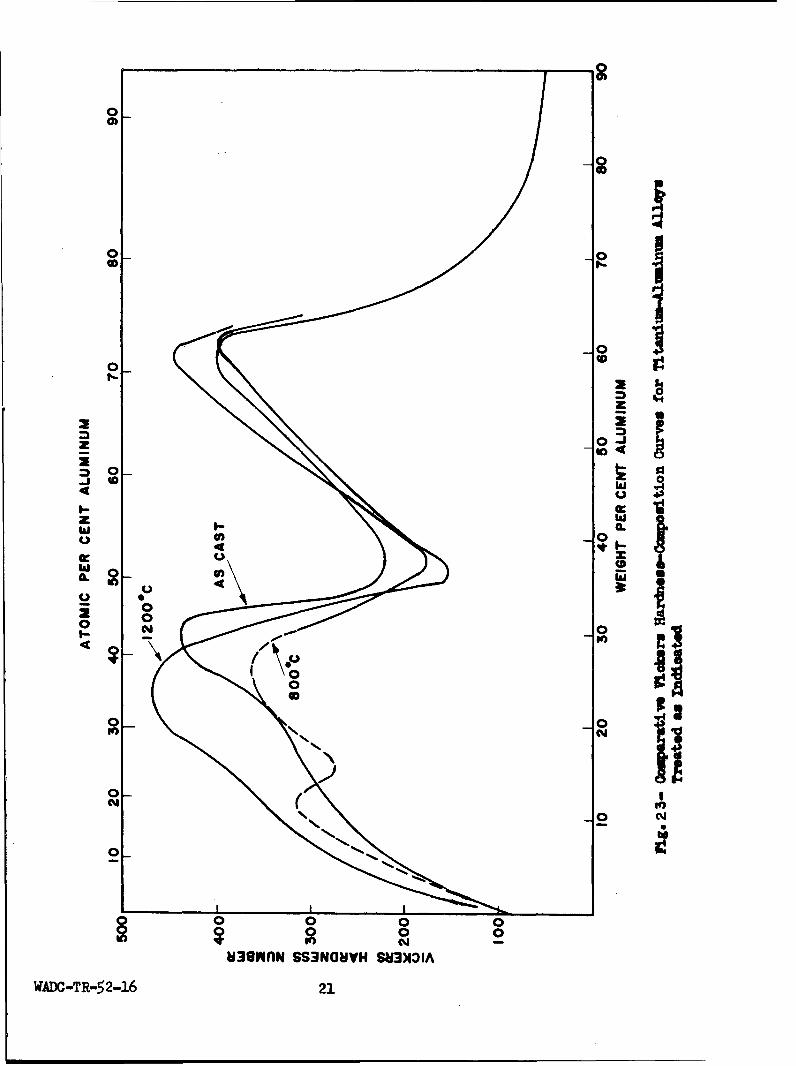
Vickers hardness data for as-cast alloys and those heat treated at8000 and 12000C are presented graphically in Fig. 23. The data includealloys from 0 to 90% aluminum.
Aluminum is a very effective hardener of alpha titanium. The hard-ness curves show an increase in hardness in the 1-25% aluminum alphasolid solution range. A maximum hardness peak is reached at 25 or 30%aluminum, depending on the treatment. This composition range exhibitedthe most scatter in hardness data. It appeared that most of the scatterwas due to the brittle characteristics of the alloys in this range ofcomposition.
Alloys containing 25-35% aluminum, which structurally revealed anincreased amount of gamma phase, showed decreasing hardness, reaching aminimum value for the 36% aluminum alloy. This alloy has been identifiedmetallographically as a single phase, gamma.
Hardness in the 40-60% aluminum composition range increases to asecond maximum in the hardness curve, which occurs at TiA1 3 (62.7% Al).
WADC TR 52-16 19

ATOMIC PERCENT ALUMINUM
10 20 30 40 50 60 70 80
1800[
* MELTEDo UNMELTED
1700- A THERMAL
SANALYSIS0
16 0 0 - • o "o •0 ~ 00
160 0 0
D 0 00\
1500 -0
O 0 0
w" 040 P oo 4,,0w 0
1400- p o0 0\0
0
1300
I I I I I ___________
10 20 30 40 50 60 70WEIGHT PERCENT ALUMINUM
Fig. 22 -Melting Jange8 for the Titanium-AlminumSyntm
WADC-TR-5216 20
0
M-1
0-0
z
z 0~-iI
44
cc x
0 09L ;
0 0I0I
oý
N-
o 0
0 0 004 2
w3emnfN SS3NOWiVH SU3NIflA
WADC-TR-52-16 21

Hardness data for alloys higher than 60% aluminum were restricted toas-cast alloys. The hardness drops sharply from 62 to 90% aluminum, andlevels off to approximately the hardness of pure aluminum.
B. The Titanium-Chromium-Iron System
When the study of the titanium-chromium-iron system was first initiated,no determination of the two binary systems titanium-chromium and titanium-iron had been made using high-purity titanium. Therefore, the first objec-tive was to accurately locate the phase boundaries using high purity alloys.The earlier and contemporary studies of the binaries are reviewed in detailin the sections of this report relating to the respective systems.
1. The Titanium-Chromium and
Titanium-Iron Systems
a. Experimental procedure
Special high purity sponge titanium, manufactured by the Bureau ofMines, was used in the preparation of many of the alloys. The analysisof this material appears in a previous section of this report. With anas-cast hardness of 105 DPN, it compares favorably with iodide titanium(70-90 DPN). As a further check on the high purity of the Bureau of
Mines titanium, samples of cold worked sheet were annealed at 100C inter-vals for 1/2 hour. The results place the transformation temperaturebetween 8800 and 890°C, in good agreement with that of iodide titanium(885*C). Microstructures obtained are identical to those of iodidetitanium, thus verifying the excellent purity of the metal.
The charges for the arc melting furnace were weighed to a thousandthof a gram and the ingots were weighed equally accurately after melting.With the exception of a few ingots in the high chromium region, onlysmall weight losses were obtained. This indicates that the actual com-positions must follow the nominal compositions very closely. The averageweight loss for iodide titanium melts was about 0.02 gram, and that forthe Bureau of Mines melts of the order of 0.2 gram. The higher weightlosses of the Bureau of Mines titanium-base alloys were due to the factthat it was charged as sponge. The results of typical check analysesare shown in Table V.
WAOC TR 52-16

TABLE V
TYPICAL CORRELATION BETWEEN NOMINAL COMPOSITION AND CHEMICAL ANALYSISFOR TITANIUM-CHROMIUM AND TITANIUM-IRON ALLOYS
Nominal Chemical AnalysisAlloy Designation* Composition,% Iron,% Chromium,%
BF14-918 14 14.26BF32-930 32 32.17BF36-934 36 35.61
BC14-957 14 14.35BC50-971 50 49.87
*B = Bureau of Mines titanium; F = iron; C = chromium. For
example, BF14-918 indicates a 14% iron alloy made withBureau of Mines titanium, heat number 918.
Most alloys capable of being deformed were cold pressed in order toincrease the rates of attaining equilibrium on heat treatment. Titanium-iron alloys under 3% iron were cold pressed 25-50%, but the 11% alloycracked with slight deformation. The 2% chromium alloy cracked withcold pressing.
Coring was observed above 114 iron and 6% chromium; therefore thesealloys were homogenized at 10500C for 24-48 hours. The annealing timesvaried from one or two days at 10500C to a month at and below 5500C.At more elevated temperatures, the times were shorter, in o'der to keepsurface contamination at a minimum. At 1260°0C, samples were annealedfor two hours, and at 1385°C, 20 minutes was the time used.
Thermal analysis, metallographic analysis after isothermal annealing,and incipient melting techniques were used to determine the melting rangeof the alloys. The samples for metallographic analysis were separatedwith molybdenum sheet to prevent contact in case of melting. Solidusdata were determined by incipient melting techniques, for which the firstvisual sign of melting on heating was used. The accuracy of the incipientmelting data is estimated to be *25°C; and that of other melting rangedeterminations is t lO°C.
b. Results and discussion
(1) The system titanium-chromium
In the first reported work on this system, Vogel and Wenderott (9)roughly outlined the phase diagram within the range of composition 42-100%chromium. They reported the existence of the compound Ti Cr 2 (42.O% Cr),was said to form a eutectic at 48% chromium and 14000C with a chromium-rich solid solution containing 26% titanium. A tentative phase diagramof the titanium-rich alloys, based on magnesium-reduced titanium, wasgiven by Craighead, Simmons and Eastwood (10). According to their data,
WADC TR 52-16 23

the transformation temperature of titanium is lowered by the addition ofchromium, giving rise to an extended beta field and a restricted alphafield. McPherson and Fontana (11) have published photomicrographs ofalloys with up to 18% chromium, prepared with magnesium-reduced titanium,after various heat treatments. They concluded that about 10% or morechromium apparently stabilizes the beta solid solution down to low tem-peratures, as no phase changes occurred in these alloys on air coolingfrom the beta field.
Micrographic analysis of the whole system by M. K. McQuillan (12),using magnesium-reduced titanium, resulted in the diagram presented inFig. 24; the data points are indicated. Metallographic evidence was givenof the decomposition of the continuous series of solid solutions betweenbeta titanium and chromium by precipitation of the inteiediate phase,Ti 2 Cr3 (62.0% Cr), within a wide range of composition. The titanium-richbeta Phase is shown to decompose eutectoidally at a temperature somewhatabove 650°C, the composition of the eutectoid being about 16% chromium.McQuillan established the fact that the only intermediate phase in thissystem is not Ti 3 Cr2 , but one having a composition close to 62 weightper cent chromium; she therefore assigned the formula Ti 2Cr3 .
The partial diagram given by Duwez and Taylor (13), determined withiodide titanium-base alloys, shows that the beta solid solution withabout 14.5% chromium decomposes at approximately 660 0 C into a eutectoidof alpha and the compound TiCr 2 (68.5% Cr). The existence of the latterwas established by study of the crystal structure, which is face-centeredcubic with 24 atoms per unit cell (MgCu 2 type). The solubility of chrom-ium in alpha titanium at the eutectoid temperature was estimated to be1% or less chromium. The solubility of chromium in beta titanium at1100°C was found to be 26.5%.
(a) Metallographic studies
The partial phase diagram shown in Fig. 25 has been determined mainlyby micrographic analysis of alloys with 0.5-75% chromium, annealed at andquenched from temperatures between 6500C and 1420°C. Results are, ingeneral, in accordance with the phase diagram given by M. K. McQuillan(12) (see Fig. 24).
High-purity Bureau of Mines sponge titanium was used in the prepara-tion of alloys. Eight iodide titanium-base alloys of 0.5-13% chromiumwere made to check any differences between the structures of the twotypes of titanium-base alloys. Comparing Fig. 25 with the insert ofthat figure, it can be seen that for the data points obtained, there isno apparent difference between the two for the P/a + P boundary.
The maximum solubility of chromium in alpha titanium is less than0.5%. Beta titanium is retained upon water quenching alloys in whichthe beta phase contains at least 7% chromium.
WADC-TR-52-16 24

z0
0 -n0 w000 a 0
0 +z U
0 0 0
OD~ 00E
0 icn
00 I
o0 010 0 z+j
/1- 0 I rx- //0
00
U)00
0 0
0 0 z00
Z0- 0 0 00 000 0 03 0 00 0o 0M00 0 0 0 000 0 02;7- CD t D f 4 1 - 0 z D I- D
WAD 0R 52-16
2 0- 5

ATOMIC PERCENT CHROMIUM
____10 20 30 40 50 60
0C 00 0 0 0 A HERMAL ARREST0ONE PHASE
1800 ~ ' ___-~ 800jXX0000 _X TWO PHASE172 -- fxx0 0_0_0 0 0 PARTIAL MELTING -
17-. 2ETI/ 0 6 x x x j x f INCIPIENT MELTINGX aiiji~2 J COMPLETE MELTING .
160 60o I%Cr 20I ~MELT tB A
001400 ~~~MELT 13800 I\jd-hO
1400 00 0
W0 0 00 0 X X I35 x
I 00 0 frx x xx x1200 - -~-------- 0---o0- *0- o0 - --x---x---b A-x X Xx-I-4
n0 0 O'X X X
cc000 0 0 0 0 x x x x ~x x x ( ~W I I )
LI I I /i
8 5 0 0 00 00 x x. X + Ti Cr2 N
800 0----- 0+-000-0-X--X-X---- _ _ -- -__--
Ix x x x X -QQX x x x x 6850--411jx x x x xxx x x
600 !___________ - -
a~ ~ a+Ti Cr2 II
400 10 20 30 40 50 60 70
WEIGHT PERCENT CHROMIUM
Fig. 25- Partial Phase Diagram of the Titanium-Chromium System. Insertshows Section of~ Diagram Duplicated with Iodide Titanium-BaseAlloys.
WADC; TR 52-16
P-6

The eutectoid point is located at 15% chromium, between 675*C and7000C. Figure 26 illustrates the eutectoid decomposition of the betaphase, and shows that it was confined mostly to the grain boundaries, evenafter 15 days' annealing at 675*C.
After annealing at 650*C for 13 days, typical lamellar eutectoid de-composition was observed only in alloys containing more than 12% chromium.The microstructures of alloys of lower chromium content consisted of fineWidmannstl.tten alpha in beta, and some alloys showed the start of eutectoidat the grain boundaries. The microstructure of such an alloy is shown inFig. 27, and is compared to the same alloy annealed above the eutectoidtemperature (Fig. 28). The amount of decomposition in alloys annealed at6500C increased with chromium content up to 22% chromium (the alloy ofhighest chromium content annealed at this temperature level). Microstruc-tures of alloys annealed at 6000C were extremely fine and unresolvable.
Oxygen contamination greatly increases the rate of eutectoid decom-position. This was proved by simultaneously annealing an 18% Bureau ofMines titanium-base alloy and a 17% Process A titanium-base alloy (con-taining approximately 0.15% oxygen) for one day at 6350C. In the highpurity 18% chromium alloy, the beta solid solution was eutectoidallydecomposed about 15%, as compared to the lower purity 17% chromium alloy,in which beta was decomposed approximately 95%.
The absence of a eutectic was established by means of both thermaland micrographic analysis. Above approximately 13500C, beta titanium andchromium are completely mutually soluble. Upon cooling alloys between 15and 75% chromium from the beta region, TiCr 2 is rejected.
Two thermal arrests were obtained in cooling curves for alloys con-taining 48, 55, 63, and 68% chromium, as showm in Fig. 25. The firstindicates the start of solidification, and the second break gives thefirst thermal evidence of the breakdown of the beta solid solution. Itwill be noted that the second arrest shows increasing deviation from theindicated P/P + TiCr 2 boundary, as the chromium content decreases. Thiscan be explained by the fact that appreciable heat evolution for thisprecipitation is detected only when relatively large quantities of com-pound are rejected.
Plicrographic evidence of the precipitation of TiCr 2 from the betaphase is given by the microstructure of a chill-cast 50% chromium alloy(Fig. 29) and that of an alloy with 48% chromium slowly cooled from themolten state (Fig. 30). These structures definitely show a Widmannst'ittentype precipitate formed by cooling from a single phase field into a two-phase field, and are not of eutectic origin.
Figures 31 and 32 illustrate the microstructures of a 66% chromiumalloy quenched from the beta and the P + TiCr 2 fields, respectively.Upon quenching from 138500 in the beta field, the solid solution brokedown into the serrated structure shown (Fig. 31). An X-ray diffractionpattern of this alloy showed it to be almost entirely TiCr 2 . Annealing
WADC TR 52-16 27

Ox
Neg. No. 3734 X500
Fig. 26An 18% chromium alloy, homogenized,annealed at 6750C for 360 hours.Eutectoid decomposition occurs mostlyalong the grain boundary. Matrix isretained • with a few compound crys-tals.
S• • ... . o -- - .o
S<I .
Neg. No. 3750 X750 Neg. No. 3751 X750
Fig. 27 Fig. 28An 8% chromium alloy, homogenized, Same alloy as Fig. 27, homogenized,annealed at 650*C for 305 hours. a annealed at 7000C for 190 hours.plus metastable P showing the start a + 3.of eutectoid decomposition in thegrain boundary.
Etchant: 60 glycerine, 20 HN0 3 , 20 HF
WADC TR 52-16 28

>. /,( -, 0.N-' , ., - ,-
Neg. No. 3514 X250 Neg. No. 3519 X250
Fig. 29 Fig. 30A 5D% chromium alloy, are melted and A 481% chromium alloy., slowly cooledchill1 cast. P with precipitate of in a graphite crucible. No eutecticcompound rejected from the cored is indicated. Structure is of Wid-solid solution during fast cooling. mannstCdtten type typical of an alloy
cooled from a one phase field intoa two phase field.
Neg. No. 3747 X250 Neg. No. 3746 X250
Fig. 31 Fig. 32A 66% chromium alloy,, annealed at Same alloy as Fig. 31, but annealed1385*C for 20 minutes and water at 1260*C for 2 hours and waterquenched. Serrated compound showing quenched. Almost entirely equiaxedthat the alloy was in the P field grains of TiCr2 with a trace of •prior to quenching.
Etchant: 60 glycerine., 20 HN0 3, 20 HF
WADC TR 52-16 29
at 12600C resulted in the microstructure shown in Fig. 32. The equiaxedgrains illustrate that the compound was formed isothermally, and thatthe alloy contains only traces of beta. From the microstructure of theseries of alloys annealed at 12600C, the compound has been shown toexist over a small composition range (67-68% Cr).
It may be noted that TiCr 2 showed twinning in the microstructuresof samples that had been deformed and subsequently annealed at 6750C.This phenomenon was not further investigated.
(b) Melting range determinations
Incipient melting data were used to outline the melting range ofalloys with up to 68% chromium. As these determinations were of a com-paratively low order of accuracy, they are used only to locate the dottedmelting range up to 40% chromium.
Detection of melting in isothermally annealed samples checked incipi-ent melting data at 24% chromium, and was used to locate the minimummelting temperatures at 45% chromium. Partial melting in annealed sampleswas also detected at higher chromium contents, thus establishing theflat solidus curve between h5 and 75% chromium.
Thermal analysis located the liquidus curve at higher chromiumcontents and verified the minimum melting point at 45% chromium. Thatcarbon contamination did not lead to large errors in thermal analysisdata was proved in the following manner: Cooling curves were determinedfor two 48% chromium-titanium alloys and the liquidus points agreedwithin less than 5°C. However, the microstructure of one showed novisible carbides (Fig. 30), while the other showed appreciable amountsof carbide in the microstructure. Thus, even though the carbon contamin-ation was apparently quite different, the thermal analysis data agreedclosely. The results of high temperature annealing treatments are shoimin Table VI, and substantiate the thermal analysis data.
WADC TR 52-16 30

TABLE VI
MELTING RANGE DETERMIATIONS FOR TITANIUM-CHROMIUM ALLOYS
A. Thezral AnalysisInflection Temperatures, *C
Nominal % Cr Liquidus Compound Rejection
68 1544 134464 1494 1342
55 1407 1271
48 (Alloy 1) 1384 1201
48 (Alloy 2) 1382 1202
40 1383
B. Annealing Treatments
Nominal % Cr Temperature, C Outward Appearance Microstructure
45 1380 No melting No melting
45 1390 Complete melting --
69 1420 No melting Partial melting
70 1420 If
72 1420 I "
75 1420 U No melting
(2) The System Titanium-Iron
In the following discussion, only the constitution of the titanium-rich alloys with compositions up to and including the phase TiFe (53.8%Fe) will be considered. Laves and Wallbaum (14) briefly reported thatthe two compounds Ti2Fe (36.8% Fe; face centered cubic with 96 atoms perunit cell) and TiFe (B2 type) exist. Wallbaum (15) also published aphase diagram showing these intermediate phases; however, apparently nodetailed work was done on the titanium-rich alloys, as no phase relation-ships based on experimental evidence were given. Craighead, Simmons andEastwood (10) found that additions of iron lower the temperature of thepolymorphic transformation of titanium, giving rise to a very restrictedrange of alpha solid solutien and stabilization of the beta solid solu-tion toward lower temperatures. Their work was confined to magnesium-reduced titanium-base alloys containing up to 2.2% iron. By measuringthe hydrogen pressures in equilibrium with very dilute solutions of
WADC TR 52-16 31

hydrogen in iodide titanium-base alloys, A. D. McQuillan (16) determinedthe P/a + P boundary above 800"C and between 0 and 5.8% iron.
By means of micrographic and X-ray diffraction methods, usingmagnesium-reduced titanium of low purity (with a transformation rangeof 860o-970°C), a general outline of the phase diagram for the titanium-rich portion of the system was established by Worner (17). He foundthat the beta phase decomposed eutectoidally at 17.5% iron and approxi-mately 600*C into alpha (with 0.9% iron) and the compound TiFe (with abody centered cubic lattice and a melting point of approximately 1250°C).A eutectic of beta, containing 25% iron, and TiFe was established at32% iron and 1060°C. Although Duwez and Taylor (18), in agreement withLaves and Wallbaum (14), reported the existence of the compound Ti 2 Fe,Worner found no evidence of this phase, either metallographically or byX-ray diffraction studies.
In the course of his work on the copper-titanium system, Karlsson(19) found some evidence to support Worner's conclusion that Ti Fe doesnot exist. Karlsson was able to show that the previously reported Ti 2 Cuwas really an oxide phase having an ideal composition Cu 3 Ti 3 0, with a
titanium-rich solubility limit close to Cu2TihO. The high oxygen contentprobably resulted from contamination during heat treatment. He proposedthat a similar phase might exist in the titanium-iron-oxygen system.
(a) Metallographic studies
Micrographic analysis of heat treated specimens and a limited amountof thermal analysis and X-ray work have been used in the determination ofthe partial phase diagram up to the composition of the first compound,TiFe (53.8% Fe). Results are in general accordance with the phase diagramgiven by Worner (17). Specimens were annealed at and quenched from tem-peratures between 5000 and 12000C. Iodide titanium was used for thepreparation of alloys containing up to 30% iron. High-purity Bureau ofN•ines sponge titanium was used for alloys of higher iron content.
The partial phase diagram is presented in Fig. 33. The eutectoidpoint lies between 5750 and 600°C, between 15 and 16% iron. No eutectoidwas observed in samples annealed at 600 0 C for as ±ong as 745 hours.Evidence of the eutectoid is shown in the microstructure of an 18% alloyannealed at 5500C for 740 hours (Figs. 34 and 35). These photomicro-graphs illustrate the fact that the decomposition has started at thegrain boundaries, and is extremely sluggish. As for the titanium-chromiunsystem, eutectoid decomposition was found only in hypereutectoid alloysand hypoeutectoid alloys near the eutectoid point. Figure 36 illustratesthe microstructure of a 13% iron alloy annealed at 550 0 C for 740 hoursand shows no eutectoid decomposition of the beta phase. Decompositionwas observed in alloys as low as 11% iron for samples annealed at 500°C.Similar to the results of the titanium-chromium system, it was found thatoxygen accelerates the euteczoid decomposition.
,qADC TR 52-16 32

ATOMIC PERCENT IRON10 0 20 30 40 50
1800II
1720o ONE PHASE
1600 • .......... x TWO PHASE\ PARTIAL MELTING
MELT + 0 COMPLETE MELTING• . \ \ ••A THERMAL ARREST
1400 \ 1
o kMELT
c r. 1 2 0 0 . . . . . m - . .. _ _
o 0 MELT + TiFe I 00xx x x x 0
1000 0-0-0o- o • -0o.o-o- X-x--X--X-X-- --- X X------- ....1 / - •
,-" 885 o00 Ooox XX X X X X 0
600 ------ X--X -x-x-x---x-•-x--x---------x- ...x
L x 88 0 0 000 x x x x x x x x x x 0•
XX X K K
400a ++TiFe -i
0 10 20 30 40 50 60
WEIGHT PERCENT IRON
F0g. 33- Partial Phase Diagram of the Titanium-Iron
Sys tern.
WADC TR 52-16
33

Neg. No. 3488 XlO0 Neg. No. 3489 X75o
Fig. 34 Fig. 35An 18% iron alloy, homogenized and Same alloy as Fig. 34, but at higherwater quenched after annealing at magnification. This clearly shows550°C for 740 hours. Eutectoid de- the eutectoid structure and primarycomposition along grain boundaries, compound in a matrix of retained t.
Neg. No. 3731 X250
Fig. 36A 13% iron alloy treated the same asthe 18% alloy (Fig. 34). a in amatrix of retained P. No eutectoidis evident.
Etchant: 60 glycerine, 20 HN03, 20 HF
WADC TR 52-16 34

The solubility of iron in alpha titanium is less than 0.5%. Betatitanium is retained upon water quenching alloys in which the beta phasecontains at least 4% iron.
The maximum solubility of iron in beta titanium at the eutectictemperature, 10800C, is 25% iron. The eutectic point lies at 32% iron.The intermediate phase coexisting with the beta solid solution corre-sponds to the stoichiometric composition of TiFe (53.8% Fe), and is shownin the single phase microstructure of a 54% iron alloy annealed at 9000Cfor 72 hours (Fig. 37).
No evidence was found of the compound Ti 2Fe (36.8% Fe), reported byother investigators (14, 18). The microstructures of the alloys in theS+ TiFe fi-eld show a consistent increase in the amount of TiFe as theiron content increases, and no other phase was indicated. It was thoughtthat Ti 2Fe might be formed by a sluggish peritectic reaction (TiFe + melt--o Ti 2Fe), and thus would not be seen in the fast-cooled arc meltedalloys. Therefore, a 36% iron alloy was held in a graphite crucibleat llO5 0C, just above the eutectic temperature, for 20 minutes and slowlycooled. If Ti2Fe exists, and is forxed peritectically, it would appearin the microstructure of this sample as a peritectic wall around theprimary TiFe phase. However, Fig. 38, a photomicrograph of the abovealloy, does not show any indication of Ti 2Fe. The structure consistsof about 20% primary compound (TiFe) and a coarse eutectic of beta andTiFe.
(b) X-ray studies
X-ray diffraction was used in an attempt to isolate the Ti 2Fe phase.Diffraction patterns of a 48% iron alloy annealed in the P + TiFe fieldgave lines which could be accounted for only by the phase mixture ofbeta titanium and TiFe. The latter phase was identified as having abody centered cubic structure with a lattice parameter of 2.982 X, ingood agreement with the results of Duwez and Taylor (18). There wasno indication of Ti 2Fe.
With Karlsson's work (19) as the impetus, alloys corresponding tothe stoichiometric composition of Ti 2Fe, Ti 3 Fe 3O, and Ti4Fe 20 were pre-pared. Iodide titanium and very pure TiO2 were used. Powder patternswere taken of the homogenized alloys. The Ti 2 Fe alloy gave predominantlythe structure of the TiFe phase, and extra lines belonging to eitheralpha or beta titanium, depending upon heat treatment. Both the Ti 3 Fe30and the Ti4Fe 20 alloys yielded single phase patterns which were almostidentical to those reported by Duwez and Taylor. A comparison of thediffraction lines is shown in Table VII. It appears, therefore, that"a ternary phase exists in the titanium-iron-oxygen system which permits"a broad replacement of iron atoms by titanium atoms.
WADC TR 52-16 35

Neg. No. 3732 X150
Fig. 37A 54% iron alloy, homogenized, an-neal~ed at 50000 for 72 hours andwater quenched. The intemnedaatephase TiFe.
Neg. No. 3645 X150
Fig. 38A 36% iron alloy, held at 1105*C,2Orninutes, and slowly cooled in a graphitecrucible. Primary TiFe plis coarseeutectic of t3 and TiFe.
Etchant: 60 glycerine, 20 HN03, 20 HF
WADC TR 52-16 36

TABLE VII
COMPARISON OF INTERPLANAR SPACINGS FOR TiF 2 0 AND Ti 2FeREPORTED ELSEWHERE (18)
dhkl' dhkl(') dhl() )
hkl Ti 4 Fe 20 Ti 2 Fe (18) hkl Ti 4Fe 2 0 Ti 2Fe (18)
332 2.386 842 1.230 1.234422 2.293 2.31 933,771,755 1.132 1.136
500,430 2.250 862 1.106 1.109431 2.203 666 1.084 1.087
333,511 2.163 2.17 775 1.016 1.019440 1.986 2.00 955,971 0.9997 0.9886
442,600 1.872 1.88 882 0.9838 0.9847622 1.745 1.72 866 0.9682 0.9697444 1.619 1.63 10,62 0.9523 0.9563
551,711 1.572 1.59 12,00-884 0.9397 0.9423553,731 i. 478 1.472 11,51-777 0.9300 0.9330650,643 1.463 1.41 10,64-12,22 0.9146 0.9172
733 1.375 1.382 10i,82 0.8711 0.8726821,742 1.353 13,,11-11,55 0.8633 o.8648660,822 1.328 1.334 11,173-13,31 o.844o 0.8456555,751 1.301 1.305 13,33-955 0.8294 0.8277
840 1.259 14,20-10,86 0.7984 0.7997911,753 1.238 1.242
(c) Melting range determinations
The results of the melting range determinations are given in TableVIII and are plotted in Fig. 33. The 22, 32, and 36% alloys were studiedby thermal analysis, which definitely established the eutectic point at32% iron and 1080 0C. The low carbon pickup of about 0.1% for the 32 and36% iron alloys indicates that the breaks in the cooling curves couldnot be greatly displaced by contamination.
To further substantiate the results of thermal analysis, and to de--termine the slope of the solidus curve at low iron contents, a series ofalloys was annealed at 12000C for 15 minutes, followed by water quenching.Figures 39 to ,42 illustrate a series of structures used to determine themelting range.
WADC TR 52-16 37

Neg. No. 3728 X250 Neg. No. 3733 X250
Fig. 39 Fig. 40A I1% iron alloy, homogenized and A 16% iron alloy treated the same aswater quenched after annealing at the 14% alloy (Fig. 39). Partial12000C for 15 minutes. Retained 3. melting in retained f.
it7. i,
Neg. No. 3729 X250 Neg. No. 3730 X250
Fig. 41 Fig. 42A 20% iron alloy treated the same as A 22% iron alloy treated the same asthe 14% alloy (Fig. 39). Greater the previous alloys. As-cast struc-amount of melting in retained J. ture showing the sample was completely
molten at temperature.
Etchant: 60 glycerine, 20 HF, 20 HNO3
WADC TR 52-16 38

TABLE VIII
MELTING RANGE DETEMINATIONS
A. Thermal Analysis
Nominal % Fe Liquidus Eutectic
22 1224
32 1082
36 1146 1080
B. 1200*C Annealing Treatments
Nominal % Fe Outward Appearance Microstructure
14 No melting No melting
16 Partial melting
18 Greater partial melting
20 Greater partial melting
22 Complete melting Complete melting
24 "-
26.3
(3) Hardness of Titanium-Chromiumand Titanium-Iron Alloys
Vickers diamond pyramid hardness tests (10 kg load) were made onseveral groups of annealed and water quenched alloys. The results ofsome of these measurements are shown in Fig. 43. The curves for thealloys quenched from 10000C are typical of hardness trends in bothsystems for samples quenched from 8000C and above. The hardness peaksin each case correspond to the compositions at which beta is retainedon quenching; i.e., 4% iron and 7-8% chromium. Beyond the peak, thehardness of chromium alloys drops to a minimum at about 13% chromium,and increases to about 800 DPN in the region of TiCr (67-68% Cr). Thetitanium-iron curve reaches a minimum at approximately 11% iron, increasesto 30% iron, &nd then shows a gradual drop to the compound TiFe (54% Fe).
Hypoeutectoid alloys of either system, annealed at 700*C for 360hours, have a + P structures and the beta is of sufficiently high alloycontent to be retained on water quenching. These mixed structures aremuch softer than the acicular products obtained by quenching from abovethe transformation temperature (see Fig. 43). By annealing at 7000C,the hardness of the 4% iron alloy was reduced to 255, and that of the7% chromium alloy, to 275 DPN.
WADC TR 52-16 39

0
0 0
0 . 00 - r4
0 0 0~ 0
0 0 00 0 0
0O0 0 0o 0t 0 0
CONI 01) SS3NaHVH 0114VHAd aNo14VIo S83)IDIA
WADC TR 52-16
40

2. The Titanium-Chromium-Iron System
The literature yields no information concerning the constitution ofthe titanium-rich corner of the titanium-chromium-iron system. The de-termination of phase relationships in isothermal sections was the experi-mental approach used to obtain the ternary phase diagram. Therefore,isotherms have been used to describe the diagram. Although applied inthe coordination of experimental data, vertical sections are not presentedat this time.
From the data obtained, which are neither complete nor final, theternary eutectoid point has been placed at approximately 8% chromium and13% iron, and slightly below 550OC. The solubility of iron and chromiumin alpha titanium is less than 1% total alloy content. Additional workis now in progress to more accurately establish the phase boundariesin the high alloy region and in space about the ternary eutectoid. Themelting range of the ternary alloys also remains to be determined.
a. Experimental procedure
As for the binary systems, the charges and the melted alloys wereaccurately weighed and weight losses were very low; therefore, nominalcompositions have been used in plotting the data.
Coring was observed in some titanium-base alloys containing over 5%total alloy content of chromium and iron. Thus all alloys containingover 5% total alloy were homogenized at 1050*C for 24 hours.
Information on the annealing times used for various temperatures isgiven in Table IX. All samples treated below 800C were first heated at900C for 2-8 hours and then slowly cooled to the temperature of finalannealing. Long holding times have been used and, with the exceptionof the lower temperature treatments, probably greatly exceeded the timerequired to reach equilibrium. Despite this careful sample preparation,some segregation was observed in a number of the microstructures.
TABLE IX
ANNEALING CONDITIONS FOR TITANIUM-CHHDMIUM-IRON ALIDYS
Temperature, OC Time, Hours Temperature, eC Time, Hours
1050 24 700 192-288
900 72 650 4328oo 144 600 576-600
75o 192-288 55D 744
In general, microscopic interpretation for the placement of phaseboundaries was consistent with the lever rule, and only in a few instaaces,where data were omitted, were major dislocations due to segregation noted.
WADC TR 52-16 41

In such cases, the phase boundaries of the isothermal sections were drawnwith emphasis on the binary intercepts, and the majority of the datawhich were in consistent agreement.
b. The space model
Figure 44 is a schematic space model of the titanium-rich corner ofthe ternary system, illustrating only the solid state reactions. PointsY and Z are in a vertical plane arbitrarily cut through the system, anddo not represent compounds.
The alpha space is bounded in the ternary system by the followingsurfaces:
IA AA2 X
A1 a1 a A A,
A2 a2 a A A2
The maximum solubility of chromium and iron in alpha titanium, point A,is at the temperature of the ternary eutectoid.
The space of the ternary beta solid solution is bounded by the fol-
lowing surfaces:
X E1 T E2 X at the X corner
Y E1 T E3 Y at the Y corner
Z E2 T E3 Z at the Z corner
Intersections of these planes produce space curves of double saturationof the ternary beta phase (E T; E2T; E T). They fall, with decreasingtemperature, intersecting at T, the ternary eutectoid point. At thispoint the following eutectoid decomposition takes place:
P(T) -- > a(A) + TiCr 2 + TiFe
Point T lies in the plane AHI. If extended, the lines AI, TD, TC, andAH would meet at the respective compounds. Tie lines TA, TC, and TDextend from T to each of the phases in equilibrium with beta at thetemperature of the ternary eutectoid.
It will be seen, that the eutectoid transformations:
ternary > - ternary a + TiCr 2 and
ternary 3 - ternary a + TiFe
take place within a temaperature range (rather than at a constant tempera-ture, as in the binary systems tit-annum-chromium and titanium-iron),resulting in the formation of the spaces: a + P + TiCr 2 and a + P + TiFe.The upper surfaces of these spaces are identical with the lower surfacesof the beta space, and their lower surface is the horizontal plane re-presenting the temperature of the ternary eutectoid.
WADO TR 52-16 42
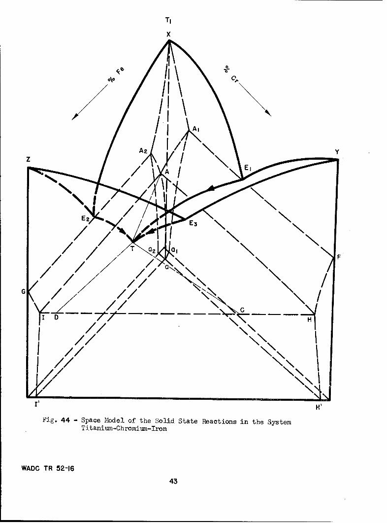
T1
x
/ //\~//
//I///I
/,/
A2 Y, A E \ý
ID H"P
H'Fig. 44 - Space Model of the Solid State Reactions in the System
Titanium-Chromium-Iron
WADC TR 52-16
43

ý*.. %.ý ,thennal sections
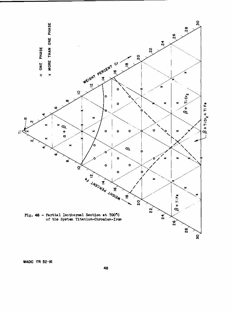
Isoth,1ermal sections at temperatures between 9000 and 550C are pre-sented in Figs. 45-51, respectively. Figure 52 shows the isotherms ofthe lower surfaces of the beta phase space; thus, it compares all theisothermal sections. At 900*C, Fig. 45, the beta field extends overalmost the entire composition area investigated. The transition fromtransformed to retained beta after water quenching these specimens isshown as a shaded line. This appears to be a straight line joining thesimilar transition points in the binary systems; that is, between 3 and4% iron, and 6 and 7% chromium. The samples of lower alloy contenttransformed partially or completely during water quenching, and thoseof higher alloy content consisted entirely of retained beta. Sectionsthrough the space model at 8000, 750*, and 7000C (Figs. 46-48) show theenlargement of the P + a and P + compound fields.
The exact location of the ternary phase boundaries at 650oC andbelow is greatly impeded by the fact that the rate of diffusion at thesetemperatures is extremely low. Even annealing times up to a month'sduration are not sufficient to start and/or complete the eutectoiddecompositions: P -- a + TiCr 2 and P -a a + TiFe, in the chromium-rich and iron-rich binary alloys, respectively. As a ccnsequence, theternary beta phase remains in a metastable state and only in the hyper-eutectoid alloys rich in chromium was microscopic evidence found of theeutectoid transformation P -> a + TiCr 2 .
In the iron-rich ternary alloys, the eutectoid decompositionS-* a + TiFe will start below the eutectoid temperature of the titanium-iron system (585 0C). Therefore, it is not surprising that at theselow temperature levels equilibrium is approached only at a very lowrate.
The solubility of iron and chromium in alpha titanium is less than1% total alloy content. The curve of maximum solubility has been arbi-trarily drawn at equal iron and chromium contents.
The eutectoid point in the titanium-chromium system (E in the spacemodel, Fig. 44) occurs at 15% chromium and 6850C. Eutectoid decompositionwas observed in ternary alloys on the chromium side, annealed at 650C.As shown in Fig. 49, many of the hypoeutectoid alloys in the a + P + TiCr 2field were actually found to be only two phase. The beta phase is ap-parently very metastable, for no eutectoid is evident even after annealingat 650°C for 432 hours. The fact that eutectoid decomposition did notoccur in the hypoeutectoid alloys of low alloy content was also observedin the binary systems (Figs. 25 and 33).
Alloys of low iron and chromium content could not be used for thedetermination of the a + P + TiCr 2 space, because of the reluctance ofthe eutectoid to develop. However, alloys of composition near the spacecurve of double saturation (EIT) showed eutectoid decomposition, andcould be used to position the space boundary at this temperature level.
WADC TR 52-16 44

wow
U- (: zJC)U
Sw~Ir
a:g 45-Pril IsteZlScina 0Co hSyte w iani0CroiuCIc
WAD TR - Z21(1)45

w0
U) O
zN
00
IX X)Z 0 0
0 2
0ig 46-Nta ateml .U a 0C hx'
Systen~ +iai~hoimfo
WADC TR 2-1
COL 046

Cl)
Iiiw0
qW Z
z0~
0 1D
OD~ 0 0 0 0 0 Kx
0AD R1 52+47A
C',D
IL
0
CL
4 00
0 x
xA
Fig.48 ParialIsoherml Sctio at700of he yst~l itniu-Chomirn-ro
2K
WADOV TR521OD48

wU)
+CC
CL N'o,
ofteSse iaiunCrmu?.Io
WAD TR+2
0 49

0)0
z C0
w e
Sytw itanlu-CI.-~-I
05

0
w G
040
wz N0
W zc
(w-
I- 1Z 00 .)
0 -
Fig.~~~C4 51 + ata stemlSetma SCoSywt0 +iaFCr~i-n In
WAD0 TR52s
510

0
ODN
AMN
0
o OD
0
000\
(NM Ok
00 0
0 0
CX'
0/
to
0/ 01
0 Y
toC\j
Fig. 52 - Tsother= of the Lower Surfaces of the Beta Phaae Space CO
in the System Titanium-Chromium-Iron N 0K)
WADC TR 52-16
52

A three phase space P + a + TiCr 2 ) of triangular cross section andconsistently increasing size with falling temperature exists between thebinary and ternary eutectoid temperature levels. The vertex point ofthis triangular field is on the space curve EIT, which was positionedby the identification of either alpha or TiCr 2 constituents in the micro-structures of alloys lying on either side of the curve. The other cor-ners of the three phase field are anchored at alpha and TiCr 2.
Only a very narrow duplex phase space exists between alpha and TiCr2,because of the restricted solubility of iron and chromium in alpha tita-nium. At equilibrium, the eutectoid reaction would be complete in thisregion, and beta is consumed. No attempt was made to locate the extentof the c + TiFe or c + TiCr 2 fieldi at high alloy contents.
The isothermal section at 6000C (Fig. 50) is similar to that at6500C, with changes only in the extent of the phase fields. Eutectoiddecomposition was observed in a greater number of alloys with fallingtemperature, although the beta phase in samples of low alloy contentcontinued to be metastable. The section at 5500C (Fig. 51) is belowthe binary titanium-iron eutectoid level, 5850C; therefore, the P + TiFeand c + P + TiFe fields should be evident. It can be seen from the datapoints that no eutectoid structures were observed in alloys on the ironside annealed at 5500C.
Although not shown, a number of vertical sections were drawn. Itwas seen from the extrapolation of data above 6500C to lower temperaturesthat many of the observed two phase samples would consist of three phasesunder equilibrium conditions. Therefore, graphical interpolation, usingall of the data known to approach equilibrium, has been used for theaccurate placement of the space curves, particularly on the iron sideof the ternary diagram.
At first appearance, the phase boundaries of the isothermal sectionsbelow 650°C may not appear to be entirely consistent with the data points.For example, at 5500C (Fig. 51), the microstructure of the 14% iron, 4%chromium alloy is one phase (P), but the alloy is located in the a + P +TiFe phase field. The apparent anomaly can be readily explained on thebasis that the composition lies very close to the space curve of doublesaturation, E2 T (see Fig. 44). Thus, no proeutectoid constituents wouldbe expected in the microstructure, and the indicated beta must be meta-stable. At equilibrium, the microstructure would show, in addition tothe beta, a eutectoid of alpha and TiFe. Other alloys in the a + P + TiFespace, of lower or higher alloy content, had proeutectoid alpha or TiFeplus beta structures. At equilibrium, these samples would also be threephase, due to the eutectoid decomposition of beta.
Figure 52, which is a composite of isotherms of the lower surfacesof the beta phase space, illustrates the good correlation obtained on com-bining all the results. The ternary eutectoid point has been placed atthe intersection of the three curves of double saturation, and is locatedat approximately 8% chromium, 13% iron, and at a temperature slightlybelow 5500c.
WADC TR 52-16 53

d. Microstructures
Only a limited number of ternary alloy photomicrographs are presented,as in general microstructures observed were similar to those for thealloys of the binary systems. Typical microstructures representativeof the various phase fields are presented in Figs. 53-59. Evidence ofthe transition from transformed to retained beta is shown in Figs. 53and 54. Alpha plus beta microstructures are illustrated in Figs. 55 and56. The first is predominantly alpha, and the second contains mostlyretained beta.
Figure 57 illustrates the a + TiCr 2 eutectoid structure of the a ++ TiCr 2 space. As previously discussed in other sections, no micro-
structural evidence of eutectoid decomposition in the a + P + TiFe spacewas observed. Also, no ternary eutectoid decomposition was noted at500*C, although this temperature is below the ternary eutectoid plane.
Figures 58 and 59 illustrate the P + compound structures; the firstcontains TiFe and the latter, TiCr 2 . A marked difference can be seen inthe appearance of the two intermediate phases. As shown in the diagrampresented, a three phase space containing both compounds exists betweenthe two duplex spaces. The precipitation of the two compounds is a reac-tion of double saturation: P -* TiCr 2 + TiFe. Thus, such microstructureswould contain the two compounds either in massive form or in a eutectoidtype structure. It was anticipated, therefore, that alloys containing
+ TiCr 2 + TiFe could be properly identified using micrographic analysis.
However, upon careful metallographic examination, only a few alloysappeared to consist of three phases, and for these positive identifica-tion was difficult. As it is only at lower temperatures that even afew of the compositions used in this study are in the P + TiCr 2 + TiFefield, more alloys of higher alloy content will be prepared and annealed.X-ray diffraction techniques will be employed to determine the extentof this three phase field.
e. Hardness
Vickers hardness data of titanium-chromium-iron alloys annealed atand quenched from temperatures between 900* and 6500C are presented graph-ically in Fig. 60. The alloys used are on the vertical section throughthe ternary system such that the iron:chromium ratio is 1:1. These alloysexhibit the same trends observed in the binary systems titanium-iron andtitanium-chromium (see Fig. 43). The hardness curves for samples quenchedabove 800*C reach a peak at about 5% total alloy content, which correspondsto the composition at which beta is retained upon water quenching. At thesame temperature level, hardness peaks were obtained at 4% iron and 7-8%chromium in the respective binary systems.
Annealing the ternary alloys at 650* or 700*C resulted in a linearincrease in hardness with alloy composition up to 10%. Such alloys havea + P structures, and are much softer than the products obtained by quench-ing from above the transformation temperature.
WADC TR 52-16 54

A
A'
Neg. No. 3879 X250
Fig. 53A 2% iron, 2% chromium alloy annealedat 9000C for 72 hours and waterquenched. Shows some transformed 1.
Neg. No. 3880 X250
Fig. 54A 2% iron, 3% chromium alloy, homo-genized, annealed at 900C for 72hours and water quenched. RetainedP3.
Etchant: 60 glycerine, 20 HN03 , 20 HF
WAO TR 52-16 55

S,6•J
Neg. No. 3881 X500 Neg. No. 3882 X500
Fig. 55 Fig. 56A 0.5% iron, 0.5% chromium alloy, A 10% iron, 4% chromium alloy, homo-water quenched after annealing at genized, annealed at 650°C for 432650°C for 432 hours, a + retained hours. a plates in retained • matrix.
S(approx. 15%).
Neg. No. 3885 X500
Fig. 57A 2% iron, 12% chromium alloy homo-genized, annealed at 650*C for 432hours. Eutectoid (a + TiCr 2 ) anda in a matrix of retained 3.
Etchant: 60 glycerine, 20 HN0 3 , 20 HF
WADC TR 52-16 56

Neg. No. 3 883 X500
Fig. 58An 18% iron., 4% chromium alloy., homo-genized, annealed at 650*C for 432hours., and water quenched. + TiFe.
Neg. No. 3884 X500
Fig. 59An 8% iron,, 16% chromium alloy., homo-genized, annealed at 650*C for 432hours, and water quenched. P + TiCr2.
Etchant: 60 glycerine., 20 HN03, 20 HF
WAD TR 52-16 57

I I I !I I I I I I I I
500
x 9000C0 8000 C
8000C 0 7500 CA 7000CC
-. 6500C
400 0\
•0
U)
Co0
wz
-o500C
z0
4x
>-70300
.650°C
200
z
100
0 5 10 15
TOTAL ALLOY %(FE, CR RATIO =I:1)
Fig. 60 - Vickers Hardness of 'Titanium-Chromium-Iron Alloys(Iron-Chromium Ratio = 1:1)
WADC TR 52-16
5R

It can be seen from Fig. 60 that the hardness of alloys in the lowercomposition range, i.e. those in the commercial alloy region, may be verygreatly changed by heat treatment. The hardness of the 5% alloy annealedat 650*C is 200 DPN, but quenching the same alloy from 900*C resulted ina hardness of over 500 DPN.
C. The Titanium-Oxygen System
The literature contains several papers concerning the compounds exist-ing in the titanium-oxygen system (20-23). The bulk of this informationis concerned with chemical and structural identification of the followingphases:
1. TiO, having a crystal lattice of the NaCl type with a melting point
of 1750°0.
2. Ti 203 , having a corundum type crystal lattice.
3. Ti02, which is stable in the following modifications: rutile andanatase I, II which are tetragonal; brookite, which has an orthorhombicstructure.
Anatase II changes at 642@C into anatase I, which is stable up to9150C, where rutile becomes the stable modification. Rutile is the moststable form of Ti02 , and will usually exist below 9150C with the trans-formation to anatase I being suppressed. At 13000C, rutile transformsto brookite, which melts at 1900°C.
The phases present in the system up to the composition of the dioxideTiO2 , and their approximate ranges of homogeneity as determined by Ehrlich(21, 22, 23), are shown in Fig. 61. These data were obtained by X-rayanalysis of samples prepared by sintering mixtures of titanium with TiOand/or TiO2 at 15000-1600°C in vacuum, followed by furnace cooling and atwo-day anneal at 7500C. Ehrlich showed that approximately 29.5 atomicper cent oxygen are soluble in alpha titanium.
The first intermediate phase, TiO, was shown to have a homogeneityrange from 38 to 55.5 atomic per cent (17-29.3 wt.%) oxygen. The nextintermediate phase, based on the composition Ti 203 (60 at.% oxygen), wasstable between 59.3 and 61.3 atomic per cent (32.5 and 34.5 wt.%) oxygen.
Ehrlich placed a new phase, having a heavily distorted rutile lattice,between 63 and 64.2 atomic per cent oxygen. The lower limit of TiO2 waslocated at 65.5 atomic per cent oxygen.
The phase relationships in titanium-rich alloys containing up to 1weight per cent (3 at.%) oxygen have been studied by Jaffee, Ogden andMaykuth (24) by micrographic analysis of annealed and quenched alloys.They found that the a/P transformation temperature is raised with in-creasing oxygen content.
In reporting the effects of small oxygen additions on the mechanicalproperties of iodide titanium, Jaffee and Campbell (25) observed that
WADC TR 52-16 59

0 N0 0
0 0 viKuTto(0 o
0o 10 (D (•-(D, -( (D
Ti0 10 20 30 40 50 60 70
ATOMIC - % OXYGEN
to •10 N
0 0"; q or.- N oT I
Ti I- 1 - I I I
0 10 20 30 40 50 60
WEIGHT- % OXYGEN
Fig. 61 - phases and phase Ranges in tie 3ystem Titanium-Oxzygen (Ehrlich)
WADC TR ý2-16 60

oxygen refines the structure, making the plates of alpha titanium smallerand the Widmannstatten pattern more regular. This was also confirmed bySutcliffe (26).
Using X-ray diffraction mid micrographic methods, Worner (27) con-finned Ehrlich's value of approximately 12.5 weight per cent (30 at.%)oxygen being soluble in alpha titanium. He also observed that oxygenaddition increased the transformation temperature. More recently, Jenkinsand Worner (28) established the limits of the a + 0 region up to 5 atomicper cent oxygen by means of measurements of thermoelectric power atvarious temperatures, and verified their results by micrographic analysis.
The titanium-oxygen phase diagram as presented here was determinedby micrographic analysis of alloys containing 0.2-30.0 weight per centoxygen, annealed at and quenched from temperatures between 7000 and 185 0 °C.Solidus and X-ray diffraction data are also presented.
1. Experimental procedure
a. Preparation of alloys
The alloys were prepared by the copper block melting method. Thecharges consisted of 1/4 inch sections of iodide titanium previouslyrolled to 1/16 inch sheet, and 1/4 inch lumps of fractured compacts ofhigh purity Ti02 . It was found that by proper placing of the charge inthe copper block, the arc (previously started against the tungsten in-sert) could be easily transferred to the charge. Even pure TiO2 waseasily melted by this method. Weight losses could not be used as a basisfor judging th. ssible variance in composition on melting, becauseingots of the bri~tle high-oxygen alloys spalled badly when the arc wasstruck during the remelting operations. However, analytical resultsfor a number of alloys (see Table X) showed very good agreement withnominal compositions. As the nominal values are well within the accuracyof the analytical results, the phase diagram as presented is based onnominal compositions. Alloys were prepared having the following nominaloxygen contents: 0.2, O.4, 0.6, 0.8, 1 . . . 40 (1% increments).
TABLE X
CHEMICAL ANALYSIS OF AS-CAST TITANIUM-OXYGEN ALLOYS
Nominal AnalyzedHeat No. % Oxygen % Oxygen
1198 3.0 3.34.0 4.2
10 9.914 14.0
1211 15 1551215 17 16.41217 19 18.51218 20 20.11219 21 21.61222 24 23.7
WADC TR 52-16 61

The following color variations were recorded by visual observationof the as-cast surface of the ingots:
TABLE XI
APPEARANCE OF TITANIUM-OXYGEN ALLOY INGOTS
CompositionRange, % 0 Color
1-11 Shiny metallic luster (silvery)
12-19 Dull metallic luster (silvery)
20-21 Dull metallic luster (possible tinge of yellow)
22-30 Shiny metallic luster changing from tinge of yellowat 22% to deep gold at 30% oxygen
31-33 Shiny metallic luster changing from gold to purple(mixture) with increasing oxygen contents
34-36 Frangible shiny shell rubbed off easily, leavingdull nonmetallic purple substance
37-38 Nonmetallic blue
39-40 Bluish rutile luster (almost metallic)
b. Annealing treatments
Annealing treatments consisted of sealing samples in Vycor or quartzcapsules, heating to temperatures ranging from 700° to 1300@C, followedby water quenching (see Table XII). Short time annealing treatments at1600*C and above were accomplished by heating a series of samples in amolybdenum sheet container in a high frequency induction furnace undervacuum conditions and quenching onto a water cooled brass plate at thebottom of the furnace. The temperature control at these high temperatureswas of the order of *25*C. The rate of heating varied considerably withthe age of the tantalum heater of the furnace, with an approximate averagerate of 20°C per minute in the temperature range 1500 0 -1900 0 C. At thesehigh temperatures, the holding times were quite short and were limitedby the accuracy of control of the induction unit. Therefore, the metallo-graphic results obtained on samples treated above 1500 0 C may not be asaccurate as those at lower temperatures. The accuracy is limited by theshort heating times (questionable equilibrium conditions) and limitedtemperature control.
WADC TR 52-16 62

TABLE XII
ANNEALING CONDITIONS FOR TITANIUM-OXYGEN ALLOYS
Annealing Time,Temperature, "C Hours Container Atmosphere
700 300 Vycor Vacuum800 120 Vycor Vacuum800 500 Vycor Vacuum900 70 Vycor Vacuum900 24 Vycor Vacuum950 72 Vycor Vacuum
1000 24 Vycor VacuumIi00 24 Quartz Argon1200 4 Quartz Argon1300 1 Quartz Argon1400 2 Quartz Argon1500 1/2 Quartz Argon
It had been reported that titanium-oxygen alloys lose oxygen atelevated temperatures. A check was made to verify this by weighingsamples before and after annealing. This was done for a complete seriesof alloys from 1 to 40% oxygen annealed at 1200"C and 1400'C for fourhours and one hour, respectively. Weight losses after annealing atthese temperatures varied from 0 to 3% of the total weight of the speci-men, with no apparent correlation with the composition of the alloy.This same amount of weight loss was obtained for unalloyed titaniumcontrol samples included with the series. It was concluded from thesedata that little, if any, oxygen was lost during annealing treatmentsup to 14OOC, under the conditions of testing used.
A further and more conclusive check of possible oxygen losses atelevated temperatures was made by X-ray diffraction methods. Diffrac-tion patterns for 5, 7, and 11% oxygen alloys quenched from 1850*C showedidentical lattice parameter measurements, for the same series of alloysquenched from 9000C.
2. Discussion of Results
a. The phase diagram
The essential features of the phase diagram presented in Fig. 62 aretwo peritectic reactions: Melt + a r± P., and Melt + a F± TiO, at 1740"and 1770"C, respectively; and a peritectoid reaction: a + Ti0C ± & atapproximately 925*C. Alpha titanium has a maximum melting temperatureof about 1900"C at 10% oxygen (approx. 25 at.% 0). The maximum solubilityof oxygen in alpha titanium is approximately 14.5% oxygen between 700*and 1600"0. The a + P field extends from 0% oxygen at 885*C to the peri-tectic temperature, 1740"C. At this temperature, the two-phase field
WADC TR 52-L6 63

ATOMIC PER CENT OXYGEN10 20 30 40 50i I I I i i I
0 SINGLE PHASE
X PHASE MIXTURE
MELT A INCIPIENT MELTING
0 PARTIAL MELTING2000- MELT + a 0 COMPLETE MELTING -3600
1900 MELT +, MELT +a -3400
1800 75 0 0 0\0 MELT + TiO
. )0 0 - 3200o 0 x1700-0 x X o0 0 0o x x
-I30001600 x x 0 0 0 0 0 X X X X X X 0
o - 28o0
,WI•,50 0 - .0 X X 00 00p 3a-i a a + TiO Ti0
4 0- 2600 tw 1400-o x xo oo oo 0 oo 0oo00 x x/ x x x 0 oo 0 o 0 0 ooo0 x 'r'
0. w~T iO ..
'"1300 0 x 0 0 0 + -2400w
Ti 2 03
1200 X0 O 0 0 0 0 0 0 0 0 0 0 x x x x x x 0 0 0 0 0 0 0 0 0 X -2200
I100 /0 x x x x x x xo 0 -200010000 //00 0 0 0 O0 0 0 0 0 0 0 X x x X x x x XX 0 0 0 0 0 0 x
: 0 -X 1800O(X 0O x x x x x x x x x 0
"0 Ix x 0 0I -1600
800- 0 0 x x x x xlI x x x x o o
a + ITiO + 1400700- 0 X x x 0
I -1200I I I I I
5 10 15 20 25 30WEIGHT PER CENT OXYGEN
Fig. 62 - Partial Phase Diagram of the Titaniui-OxygenSystem
-JADC TR 52-16 6h

extends between approximately 1.8 and 4.3% oxygen. The titanium-richsection of the equilibrim diagram, shown in Fig. 63, depicts the effectof dilute solutions of oxygen on the transformation temperature from885* to 1500oC.
The intermediate phase, TiO, is homogeneous over a broad range ofcomposition from about 20.5 to 29.5% oxygen at 1400 0C, and from about23.5 to 29.5% oxygen at 800*C. At about 9250C, an intermediate phase,delta, forms from the peritectoid reaction a + TiO 42 4, between 18 and20% oxygen. This composition range includes the stoichiometric ratioscorresponding to the formulas Ti 3 02 (18.2%) and Ti403 (20.0%).
b. Structural characteristics
Microscopic studies involved the evaluation of both etched and unetchedstructures as revealed by means of ordinary reflected light and polarizedlight, respectively. Typical microstructures illustrating various phasefields depicted in the diagram are shown in Figs. 64-80.
Illustrations of structures characteristic of alloys quenched fromthe beta field are shown in Figs. 64 and 65. A 0.2% oxygen alloy quenchedafter 48 hours at 950°C revealed a serrated alpha type of transformationstructure, as shown in Fig. 64. Specimens quenched from the beta fieldbut with compositions nearer the P/a + P boundary showed a basket weavetype of transformation structure (Fig. 65). This transformed beta struc-ture was coarser, the higher the temperature of treatment, as shown inFig. 66.
Microstructures of alloys quenched from the a + P field are shownin Figs. 67-69. At 1000 0C,the amount of alpha phase in a 1.0% alloy wasestimated as approximately 30%. The a + P structure, as shown in Fig.67, indicates that the white alpha phase was present at the temperatureof treatment and the dark structure in the interstices was formed by thetransformation of the beta phase during the quench. Figure 68 shows thatthe last traces of beta occur essentially at the alpha grain boundaries.Aside from extensive growth of constituents, the high temperature a +structures are similar to those of alloys quenched from the lower tempera-ture (Fig. 69).
The structure of the alpha phase of a 12% oxygen alloy quenched from12008 and 18500 C, respectively, is shown in Figs. 70 and 71.
The a + TiO mixture is characterized by banded twin-like structures.Near the a/a + TiO phase boundary small patches of a banded structurewere observed in the alpha titanium matrix (Fig. 72). The structures ofalloys containing 16-18% oxygen consisted almost entirely of plate-likebands, as shown in Figs. 73 and 75. On the basis of Ehrlich's (22) in-vestigations and X-ray diffraction studies carried out in connection withthis work, this banded structure was interpreted to be a mixture of thealpha phase and Ti0. It was impossible to delineate between the twophases. Annealing at 17000C coarsened the structure considerably (Fig.74), but there was no tendency for the phases to coagulate. Figure 75
WADC-TR-52-16 65

ATOMIC %
I 2 3 4 5 6 7 8 9 I0 II 12 13 14 15 16I I I ] I I I I I I I I I I I
1500- 0 X X X 0
1400-0 0 0 0 0 X X X 0 0
01300-0 o 0 0 X X X 0 0
p a-Ip al
t 1200- 0 0 000 X X 0 0 0
1100- 0 00 x
1000-00 X X 0 0 0 0
O-ONE PHASE900 X X X 0 0 X-PHASE MIXTURE885
80I I I0.2 0.4 0.6 0.81.0 2.0 3,0 4.0 5.0 6.0
WEIGHT PER GENT OXYGEN
Fig.63 - Titaniurr Rich Portion of the Titanium-OxygenSystem
WJADC TR-52-16 66
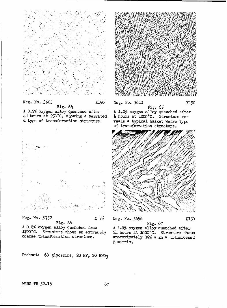
¾~A.
IN
Neg. No. 3903 Fg64x150 Neg. No. 3611 Fg65X150
A 0-2% oxygen alloy quenched after A 1,0% oxygen alloy quenched after48 hours at 950%C, showing a serrated 4 hours at 12000C. Structure re-cL type of transformation structure.* veals a typical basket weave type
Of transformation structure.
Neg. o. 3752 X75 Ng. NFig.66 365 Fi. 67X15
A 0*% oyge aloy qenced rom A 1.% oyge aloy qenced fte,17000c.~~~~~~~~~~~~~~~ Stutr-hw neteey 2 husa oo tutr hw
cors tanfomaio trctre a~rxiatl 3% i atrnsoreP1 marx
Etchant: 60 glcrn,27F 0H0
WADC TR52-16 6

Neg. No. 3657 X150 Neg. No. 3753 X 75
Fig. 68 Fig. 69 UnetchedA 2.0% oxygen alloy quenched after A 3.0% oxygen alloy quenched from24 hours at 1000°C. Structure shows 1700"C. Structure shows duplex capproximately 95% a, with transformed (white) plus transformed P (dark).
Sin the grain boundaries. Note the large grain growth.
Neg. No. 3612 PL, X 75 Neg. No. 3754 PL, X 75
Fig. 70 Fig. 71A 12% oxygen alloy quenched after 4 A 12% oxygen alloy quenched fromhours at 12000C. Structure shows 18500C. Large equiaxed grains ofpolyhedral grains of a titanium solid a titanium existing at a tempera-solution. ture higher than the melting point
of pure titanium.
Etchant: 60 glycerine, 20 HF, 20 HN03
WADC TR 52-16 68

\ AA
Neg. No. 36146 PLt, X 75 Neg. No. 36114 PLt, X 75
Fig. 72 Unetched Fig. 73 Une tchedA 15% oxygen alloy quenched after 14 A 17% oxygen alloy quenched after 14hours at 120000. Structure shows hours at 1200*C. Nearly :100% twinnedpatches of banded a + TiO phase structure of a two phase mixtu~re ofmixture in a titanium matrix, a + TiO.
Neg. No. 3755 PL., X 75 Neg. No. 37148 PL., X500
Fig. 714 Unetched Fig. 75 UnetchedA 17% oxygen alloy quenched from A 17% oxygen alloy quenched after17000C. Coarse banded structure 2 hours at 11400*C. Banded a + TiOcharacteristic of the a + TiO field. stru~cture at higher magnification.
WADC TR 52-16 69

Neg. No. 3615 PL, X 75 Neg. No. 3768 PL., X150
Fig. 76 Unetched Fig. 77 UnetchedA 19?1 oxygen alloy quenched after 4 An 18% oxygen alloy quenched afterhours at 12000C. ai + TiO phase with 120 hours at 8000C. Stru~cture showstraces of massive ai at grain bound- the precipitated 8 phase with thearies. Note decreased amount of twin- banded a + TiG structure in the back-ning. ground.
Neg. No. 3904 PL,0 X150 Neg. No. 3769 FLý, X150
Fig. 78 Unetched Fig. 79 UnetchedA 20% oxygen alloy quenched after A 22% oxygen alloy quenched after500 hours at 800*C. Approximately 120 hours at 800*C. Small. particles20% 6 phase precipitated in a TiC) of 6 phase in a TiO matrix.matrix.
WADC TR 52-16 70

Neg. No. 3616 X75
Fig. 80A 29% oxygen alloy quenched after 4hours at 12000 C. Structure showspolyhedral grains of TiO phase.
Etchant: 60 glycerine, 20 HN0 3 , 20 HF
WADC TR 52-16 71
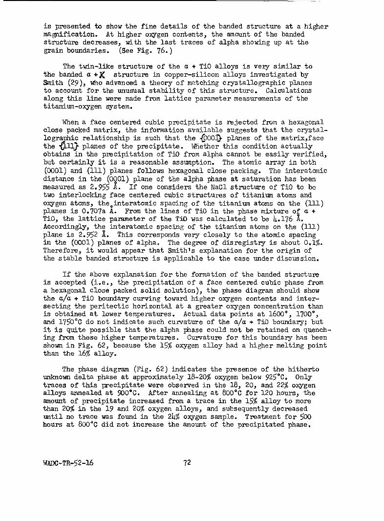
is presented to show the fine details of the banded structure at a highermagnification. At higher oxygen contents, the amount of the bandedstructure decreases, with the last traces of alpha showing up at thegrain boundaries. (See Fig. 76.)
The twin-like structure of the a + TiO alloys is very similar tothe banded a + K structure in copper-silicon alloys investigated bySmith (29), who advanced a theory of matching crystallographic planesto account for the unusual stability of this structure. Calculationsalong this line were made from lattice parameter measurements of thetitanium-oxygen system.
When a face centered cubic precipitate is rejected from a hexagonalclose packed matrix, the information available suggests that the crystal-lographic relationship is such that the (0001) planes of the matrixfacethe fll• planes of the precipitate. Whether this condition actuallyobtains in the precipitation of TiO from alpha cannot be easily verified,but certainly it is a reasonable assumption. The atomic array in both(0001) and (111) planes follows hexagonal close packing. The interatomicdistance in the (0901) plane of the alpha phase at saturation has beenmeasured as 2.955 A. If one considers the NaCl structure of TiO to betwo interlocking face centered cubic structures of titanium atoms andoxygen atoms, theointeratomic spacing of the titanium atoms on the (111)planes is 0.707a A. From the lines of TiO in the phase mixture of a +TiO, the lattice parameter of the TiO was calculated to be 4.176 X.Accordingly, the interatomic spacing of the titanium atoms on the (111)plane is 2.952 1. This corresponds very closely to the atomic spacingin the (0001) planes of alpha. The degree of disregistry is about 0.1%.Therefore, it would appear that Smith's explanation for the origin ofthe stable banded structure is applicable to the case under discussion.
If the above explanation for the formation of the banded structureis accepted (i.e., the precipitation of a face centered cubic phase froma hexagonal close packed solid solution), the phase diagram should showthe a/a + TiO boundary curving toward higher oxygen contents and inter-secting the peritectic horizontal at a greater oxygen concentration thanis obtained at lower temperatures. Actual data points at 16000, 17000,and 17500 C do not indicate such curvature of the a/a + TiO boundary; butit is quite possible that the alpha phase could not be retained on quench-ing from these higher temperatures. Curvature for this boundary has beenshown in Fig. 62, because the 15% oxygen alloy had a higher melting pointthan the 16% alloy.
The phase diagram (Fig. 62) indicates the presence of the hithertounknown delta phase at approximately 18-20% oxygen below 9250C. Onlytraces of this precipitate were observed in the 18, 20, and 22% oxygenalloys annealed at 900*C. After annealing at 800°C for 120 hours, theamount of precipitate increased from a trace in the 15% alloy to morethan 20% in the 19 and 20% oxygen alloys, and subsequently decreaseduntil no trace was found in the 24% oxygen sample. Treatment for 500hours at 800°C did not increase the amount of the precipitated phase.
WADC-TR-52-16 72

The banded structure appeared to break down with the appearance of theprecipitate at 8000 and 9000C. Figures 77-79 are presented to show theappearance of the precipitate as revealed in the 18, 20, and 22% oxygenalloys annealed at 8000C.
Figure 80 depicts the single phase TiO structure of a 29% oxygenalloy.
The determination of phase relationships for alloys containing 30-40weight per cent oxygen was not attempted because most of these alloys weretoo friable to prepare by metallographic techniques after heat treatment.By extremely careful handling, a series of samples of as-cast alloys from30 to 40% oxygen were prepared for examination.
A phase mixture of TiO + Ti 203 was observed in the as-cast 31-32%oxygen alloys, while the 33% alloy appeared to be a single phase, corres-ponding to Ti 20 3 . A mixture of Ti 0 + TiO2 was revealed in 34-37%oxygen alloys, and the as-cast 38-rO0 oxygen alloys appeared to becored single phase structures of TiO2 . These phases and phase rangesconfirm, in general, X-ray diffraction studies reported by Ehrlich.
c. Melting range determinations
Solidus data for this system as determined by incipient melting tech-niques are shown in Table XIII, and also in Fig. 62, together with meltingrange data obtained by annealing treatments. These results indicatewhether the specimens were completely melted, partially melted, or un-melted. As shown in the diagram, the annealing data are in fairly closeagreement with the incipient melting results.
The temperature of the peritectic reaction Melt + a • wasplaced between 17300 and 1750*C, because after annealing at 1730 0C the2, 3, and 4% oxygen alloys show an a + P structure with no evidence ofmelting; whereas the treatments at 17500 C gave micro structures showingcomplete melting, a + partial melting, and unmelted a, respectively, forthe same alloys. Similarly, the peritectic temperature of theMelt + a .2 TiO reaction was placed at 17700C as determined by examina-tion of a series of specimens which showed various amounts of meltingat 1800*C and did not exhibit melting when treated at17500C. Typicalperitectic microstructures were not obtained in any of the alloys ateither of the indicated perltectics. Between the two peritectics, amaximum melting point of approximately 19000C at 10% oxygen was obtainedfor the alpha phase.
The incipient melting temperature for a 25 weight per cent oxygenalloy, corresponding to the theoretical composition TiO, was determinedto be 17600C, which is in very close agreement with a previously reportedmelting point of 1750*C (30).
WADC TR 52-16 73

TABLE XIII
MELTING TEMPERATURES OF IODIDE TITANIUM-OXYGEN ALLOYS
Weight % Melting Weight % MeltingOxygen Point*, 0C Oxygen Point*, °C
0 1725 14 18402 1750 15 18303 1750 16 17804 1776 18 17806 1822 20 17708 1850 22 1765
10 1905 25 176011 1875 26 177012 1875 27 174013 1870 30 1725
*Accuracy of determination approximately t250C.
d. X-ray diffraction studies
X-ray diffraction studies were undertaken to determine the structureof the intermediate phase TiO and, by means of the parametric method, tocheck certain points on solubility boundaries as established by metallo-graphic observations.
The patterns were taken in a 14 cm Debye-Scherrer powder camerausing filtered CuKa radiation. The specimens were prepared largely bycrushing and screening. Only at low oxygen contents was it necessaryto use filing to prepare powdered specimens. Lattice parameters werecalculated by solution of simultaneous equations for a number of highangle lines or by the well-known cosine square extrapolation in the caseof cubic structures.
(1) Alpha primary solid solution
This phase possesses the hexagonal close packed structure of thelow temperature allotropic modification of titanium. The lattice para-meters of this structure as a function of oxygen content are presentedin Fig. 81. The pronounced increase in the "c" parameter would tend toconfirm that this is an interstitial type of solid solution.
In general, there is some deviation from the results of Ehrlich'swork, especially at low oxygen contents. The direction of the deviationpoints to the relative impurity of his titanium metal. From the 11c"parameter of the alpha phase in a phase mixture with TiO as quenchedbelow 900*C, the saturation composition of alpha was determined as 3V40.5atomic per cent (14.5 wt.%) oxygen. This is in exact agreement withthat value established by metallographic examination.
WADX TR 52-16 74
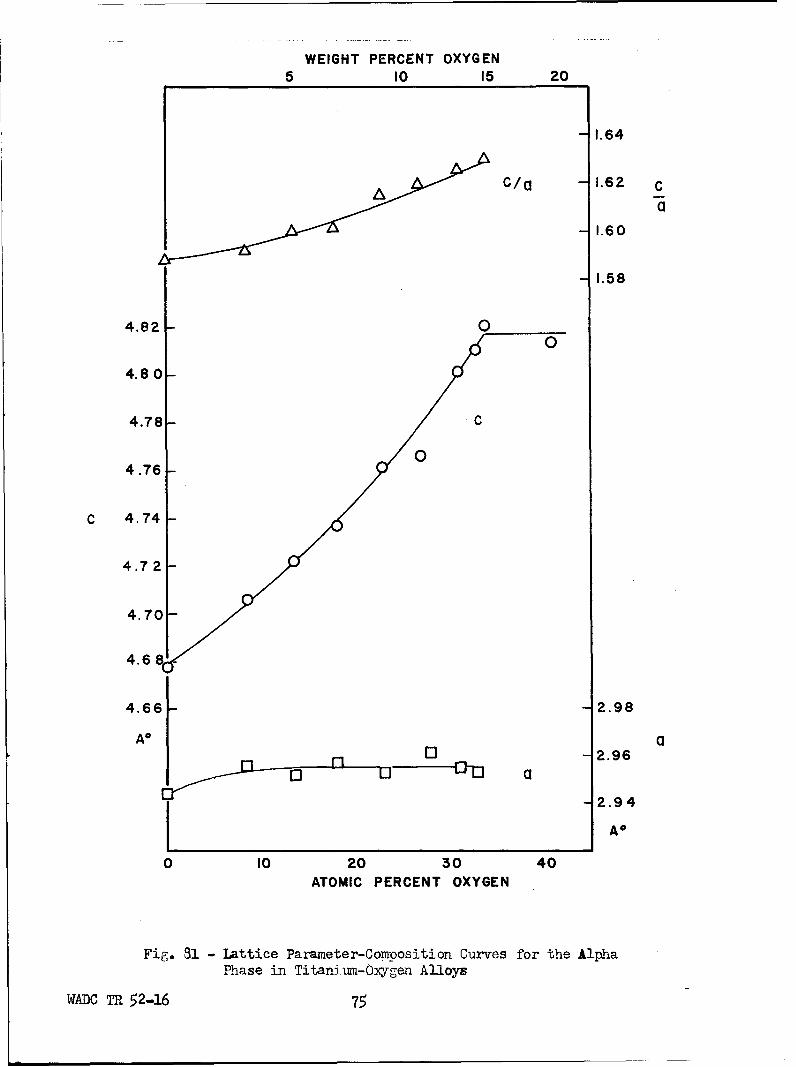
WEIGHT PERCENT OXYGEN5 10 15 20
- 1.64
C/a -1.62 c
a
- 1.60
- 1.58
4.82 - 00
4.80 -
4.78 - C
4.76
C 4.74
4.72
4.70-
4.68
4.66 2.98
A a01 -2.96
-2.94
A*
0 10 20 30 40ATOMIC PERCENT OXYGEN
Fig. 31 - Lattice Parameter-Composition Curves for the Alpha
Phase in Titanium-Orgen Alloys
WADC TR 52-16 75

(2) The intermediate phase TiO
Ehrlich has reported this phase to have a cubic structure of the NaC1type. This was confirmed by the present work. The lattice parameter as"a function of oxygen content is shown in Fig. 82. It will be seen that"a simple linear relationship occurs. The results are quite close to thosereported by Ehrlich. From the pattern of a phase mixture field as quenchedfrom 9000C and containing 40 atomic per cent oxygen, the parameter of theTiO phase was calculated to be 4.180 A. This sets the saturation composi-tion of TiO on the titanium side for 9000C at 46tO.5 atomic per cent (ap-proximately 23 wt.%). This agrees closely with the metallographic estimateof 23.5 weight per cent.
(3) The intermediate phase between alpha and TiO
On long term annealing of alloys containing between 15 and 23 weightper cent oxygen below 900*C, metallographic examination disclosed thepresence of a new phase tentatively named delta. Diffraction patternsof these structures showed a large number of new.faint lines which couldnot be accounted for by either alpha or TiO. Although the determinationof the structure of a new phase is best performed when the phase has beenisolated, this was not possible. As an alternative, which can only pro-vide tentative results, the extra lines were examined as a group. Itwas found possible to index all but one of these lines on a Hull-Davychart for the tetragonal system. The lattice parametgrs calculated forthis tetragonal lattice are: c = 6.645 1, a = 5.333 A, c/a = 1.246. Themeasure of success in relating calculated to observed spacings is shownin Table XIV. The check is quite close.
e. Hardness determinations
Vickers pyramid hardness data (5 kg load) for alloys with from 0.2to 30% oxygen are presented graphically in Fig. 83. Two curves are shown,one representing the hardness of as-cast alloys and the other, the hard-ness of a series of alloys annealed at 1000*C.
The hardness curves show an increase from approximately 170 to 950and 1200 Vickers in the alpha solid solution range of 0.2-13% oxygen.The impressions in specimens of this range of composition were of uniformshape, despite cracks and chipping due to brittleness, which usuallyaccompanies extremely high hardness. On the other hand, impressions inspecimens in the 14-20% oxygen range of composition were surrounded bydeformation bands. This evidence of ductility supports the drop in hard-ness for alloys which microscopically revealed the banded a + TiO phasemixture. From 20 to 30% oxygen, hardness again increases to extremelyhigh values.
WADC TR 52-16 76

00
0 I0
0
0 U4)
H-
0
00
H0
0oU
0) 0
oc
w -0
00
.V '813WVSd 3:DIIV-
TADC~~ T*qH2167

TABLE XIV
SUI1ARY OF OBSERVED AND CALCULATED DATA
ON THE DELTA PHASE
ObservedIntensity hiT dobserved calculated
vw 112 2.474 A 2.493 A
vw 120 2.373 2.385
vft ? 2.324 ---vft 202 2.058 2.079
ft 220 1.874 1.885
vvft 221 1.805 1.814
vw 301 1.716 1.717
vvft 004 1.655 1.661
vw 223 1.432 1.435
vw 204 1.414 Ib410
vvft 303 1.386 1.386
VVft 105 1.293 1.289
vw 115 1.242 1.253
vvft 304 1.219 1.214
vft 240 1.191 1.193
ft 324 1.102 1.104
ft 502 1.014 1.016
ft 334 0.9999 1.002
vw = very weak
ft = faintvft = very faintvvft = very very faint
VADC TR 52-16 78

1 40
* ARC MELTED ALLOYS1300-
o WATER QUENCHED AFTER 24 HRS.
1200- AT 10000 C
1100- Ile
/ I / /
1000- ///
900- //
/800 /S/ \ /
,, \/
Q700- //S/ \/
/0
500- 0 \w /
<0 o
300-
200 -
100
00 5 10 15 20 25 30
WEIGHT % OXYGEN
Fig. 83 - Vickers Diamond Pyramid Hardness vs Oxygen Content
WADC TR 52-16 79

IV. SUMMARY OF RESULTS
A. The Titanium-Aluminum System
The principal features of the diagram are as follows: A peritecticreaction, P + melt • y, between 34.5 and 38.5% aluminum at approximately1460OC. A second peritectic reaction, y + melt = TiAI3 , between 60 and64% aluminum at 1340C. A peritectoid reaction, P + y • a, between 29and 34.5% aluminum at approximately 1240OC. The P a transformationtemperature is raised from 885*C at 0% aluminum to 12--40C at 29% aluminum.A narrow a + P field is indicated. The beta phase transforms to serratedalpha on quenching. The solubility limit of aluminum in alpha titanium is24.5% at 900*C. The maximum solubility of aluminum in beta titanium is34.5% at 1J4 60"C. The lattice parameters of the solid solution change con-siderably with initial additions of aluminum and level off near the solu-bility limit. X-ray diffraction patterns confirmed the metallographicobservation that beta is not retained by rapid quenching. Gamma phase isof variable composition, from 37 to 60% aluminum at the solidus and from35.5 to about 44.5% aluminum at 8000C. The gamma phase has an orderedface centered tetragonal lattice, with an axial ratio close to unity, andis based on the composition TiAl. Increasing aluminum ccntent increasesthe axial ratio slightly. The hardness of alpha solid solution alloysincreases with the addition of aluminum to titanium. The gamma phase hasa minimum hardness at 36% aluminum, which increases with further additions,of aluminum, reaching a maximum at the composition TiA13 .
B. The Titanium-Chromium System
The transformation temperature of titanium (885"C) is lowered withincreasing chromium content, resulting in a eutectoid decomposition ofbeta at 15% chromium and 6850C into alpha, cactaining less than 0.5%chromium, and the intermediate phase, TiCr 2 . The beta phase is retainedon quenching alloys in which beta contains 7% or more chromium. Betatitanium and chromium are cempletely mutually soluble at high temperatures,beta decomposing at 1350"C into TiCr 2 , which exists within a narrow rangeof composition from about 67 to 68% chromium. The melting temperaturesdecrease from that of titanium (17200C) with increasing chromium content,reaching a minimum at 45% chromium and 1380C.
C. The Titanium-Iron System
The transformation temperature of titanium drops with increasing ironcontent, resulting in a eutectoid decomposition of beta at 15-16% ironand 585*C into alpha, with less than 0.5% iron, and TiFe. Beta is retainedin alloys in which the beta phase contains 4% or more iron. A eutecticexists at 32% iron and 1080"C between beta, having a composition of 25%iron, and TiFe. The intermediate phase, TiFe, occurs at 54% iron and isapparently formed peritectically.
Hardness curves are presented for several groups of annealed and waterquenched alloys of both systems, showing the typical results obtained over
WADC TR52-16 80

the range of compositions investigated.
D. The Titanium-Chromium-Iron System
The outstanding feature of the titanium-chromium-iron system is theternary eutectoid point at approximately 8% chromium and 13% iron at about540*C. The maximum solubility of iron and chromium in titanium is lessthan 1% total alloy content. The change from transformed to retainedbeta on water quenching from the beta field occurs along a straight linejoining the similar transition points in the two binary systems. Theternary system shows the same hardness trends indicated for the two bin-aries. A peak hardness is obtained at the composition where the transi-tion occurs from transformed to retained beta. Work on the titanium-chromium-iron system is not completed, and will be concluded during tfienext year's extension of the project.
E. The Titanium-Oxygen System
The titanium-oxygen phase diagram has the following features: Aperitectic reaction: Melt + a 49 0, between 1 and 5% oxygen, at ap-proximately 1740OC. A second peritectic reaction: Melt + a ' TiO,between 14.5 and 20.5% oxygen at approximately 17700C. A peritectoidreaction: a + TiO ± 6 between 14.5 and 23.5% oxygen at approximately925*C. The alpha phase exhibits a maximum melting point of approximately1900C at about 10% oxygen. The solubility limit of oxygen in alphatitanium is approximately 14.5% oxygen from 800* to 1700C. The latticeparameters of the alpha solid solution increase with increasing oxygencontent. X-ray diffraction patterns for the TiO phase indicate a cubicstructure of the NaCl type, with a linear decrease in parameter constantswith increasing oxygen content. Lattice parameter measurements confirmedthe alpha and TiO solubility limits determined by micrographic methods.The existence of the newly discovered 5 phase was confirmed by X-raystudies, and the structure was tentatively identified as tetragonal.The composition range in which the new phase occurs corresponds to thestoichiometric ratios for either Ti 30 2 or Ti4 03.
A marked increase in hardness was obtained with the addition ofoxygen to titanium. The hardness curve dipped to a minimum for a + TiOphase mixture alloys and then showed a rapid increase for the TiO solidsolution alloys.
V. FUTURE WORK
The titanium-chromium-iron partial phase diagram remains to be com-pleted. The melting range will be determined. A more intensive studywill be made with new alloys and annealing treatments to pin-point theternary eutectoid. The phase limits of the P + TiFe + TiCr 2 space willbe located using additional alloys and X-ray diffraction techniques.
WADC TR 52-16 81

A Study will be made to determine the phase relationships broughtabout by oxygen additions to the ternary systems. This work was suggest-ed by the discovery of the TiBFe 3 O phase, which may in some ways influencethe properties of commercial .itanium-chromium-iron alloys.
VI. CONTRIBUTING PERSONNEL
The following personnel were the major contributors to the work re-ported herein:
E. S. Bumps Titanium-aluminum and titanium-oxygensystems
M. Hansen SupervisorC. A. Johnson MetallographyH. D. Kessler Project engineerW. Rostoker X-ray diffraction analysisR. J. Van Thyne Titanium-chromium, titanium-iron, and
titanium-chromium-iron systems
VII. LOGBOOKS
Data related to the work are recorded in the following Foundationlogbooks: B-2019, B-2020, C-1283, -1284, -1285, -1293, -129h, -1559,-1886.
PADC TR ,52-16 82

BIBLIOGRAPHY
1. D. I. Brown, Iron Age 1950, Sept. 14, 85-88.
2. Navy Contract No. NOa(S)8698, 1948; see also E. I. Larsen, E. F.Swazy, L. S. Busch, and R. H. Freyer, Metal Progress 55, 1949, 359.
3. Private communication by P. Duwez (April 23, 1951).
4. M. Hansen, Der Aufbau der Zweistofflegierungen, J. Springer, Berlin,1936, 158-160.
5. W. L. Fink, K. R. Van Horn and P. M. Budge, Trans. AIME, Inst.Met.Div. 93, 1931, 421-436. Disc. 436-439.
6. G. Brauer,Z.anorg.allg.Chem. 242, 1939, 1-22.
7. K. Schubert, Z.Metallkunde 41, 1950, 420-421.
8. W. Manchot and E. Leber, Z.anorg.allg.Chem. 150, 1926, 26-34.
9. R. Vogel and B. Wenderott, Arch.f.Eisenhiittenwesen 14, 1940, 279.
10. C. M. Craighead, 0. W. Simmons, and L. W. Eastwood, Trans.AhIE 188,1950, 498-499.
11. D. J. McPherson and M. G. Fontana, Trans.ASM 43, 1951, 1098-1125.
12. M. K. McQuillan, J.Inst.Metals 79, 1951, 379-390.
13. P. Duwez and J. L. Taylor, ASM Preprint No. 3, 1951.
14. F. Laves and H. J. Wallbaum, Die Naturwissenschaften 27, 1939, 674-675.
15. H. J. Wallbaum, Arch.f.Eisenhiittenwesen 14, 1941, 521-526.
16. A. D. McQuillan, J.Inst.Metals 79, 1951, 73-88.
17. H. W. Worner, J.Inst.Metals 79, 1951, 173-188.
18. P. Duwez and J. L. Taylor, Trans.AIME 188, 1950, 1173-1176.
19. N. Karlsson, J.Inst.Metals 79, 1951, 391-405.
20. C. W. Carstens, Z.Kristallographie 67, 1928, 260.
21. P. Ehrlich, Z.Elektrochemie 45, 1939, 362-372.
22. P. Ehrlich, Z.anorg.allg.Chem. 247, 1941, 53-64.
WADC TR 52-16 83

23. P. Ehrlich, Z.anorg.allg.Chem. 259, 1949, 1-41.
24. R. I. Jaffee, H. R. Ogden, and D. J. Maykuth, Trans. AI4E 188, 1950,1261-1266.
25. R. I. Jaffee and I. E. Campbell, Trans. AIME 185, 1949, 646-654. AlsoJ.Metals (Sept. 1949) T.P. 2681.
26. D. A. Sutcliffe, Royal Aircraft Establishment RAE Technical Note No.MET 141.
27. H. W. Worner, Australian Engineer 152, Nov. 1950.
28. A. E. Jenkins and H. W. Worner, J.Inst.Metals 80, 1951, 157-166(Dec.).
29. C. S. Smith, Trans. AIME 137, 1940, 313-333.
30. J. W. Hickman and E. A. Gulbransen, Anal.Chem. 20, 1948, 158-165.
WADC TR 52-16 84

APPENDIX I
A THEORETICAL ANALYSIS OF THE STRUCTURE OF TiO
by W. Rostoker
From density measurements, Ehrlich (1) has shown that the large rangeof miscibility may be interpreted in terms of titanium and oxygen vacantsites, respectively, on the high and low oxygen sides of the TiO composi-tion. However, Ehrlich considered this phase to possess an ionic typeof bonding and the vacant site phenomenon required the postulate of mix-tures of mono- and divalent and of di- and trivalent titanium. Considera-tion of certain factors seems to indicate that the NaCl structure exhibitedderives from factors other than ionic bonding.
0
From Pauling's (2) data, the diameter of the 0- ion is 2.80 A. Thediameter of the divalent titanium atom may be calculated from the expres-sion (2)
DTi 2+ = DT4+ - =3.45 A
The assumption has been made here that titanium in the pure state or inprimary solid solutions is a tetravalent metal. Support has been foundfor this (3) from a consideration of the Brillouin Zone and lattice para-meters of the alpha primary solid solution in the titanium-aluminumsystem. A calculation of the lattice pargmeter of the TiC phase, assum-ing ionic bonding, yields the value 6.25 A, which is considerably inexcess of that observed. On the other hand, using the diameter of tetra-valent titanium and of the oxygen atom which can be derived from thealpha phase lattice parameters gives a value of 4.21 A, which is veryclose to that observed.
As a further check on the hypothesis that the TiO phase has metallicbonding, a measurement was made of electrical resistivity. This 'measure-ment was made on a cast button of variable dimensions so that the resultsare likely to be in error on the high side by a factor of as much as two.The resistivity obtained was in the order of 3000 microhm-cm, whichdefinitely excludes the possibility of either covalent or ionic bonding.
The magnitude of resistivity suggests a "full" Brillouin zone con-dition (in the sense of preceding an overlap). Because of the low scat-tering power of oxygen, the TiO structure may be considered as a facecentered cubic lattice of titanium atoms. According to Raynor et al.(W), the second Brillouin zone for a face centered cubic structure cancontain, on a volumetric estimate, four electrons per atom. An inscribedsphere corresponds to 2.49 electrons per atom but, as Raynor points out,the Fermi distribution within the second zone would be expected to befar from spherical. Accordingly, we may expect the full second zone
woe TR 52-16 85
(electronic concentration prior to overlap) to contain 2.49-4 electronsper atom. From the deduction that the TiO structure is not ionic, itmust be concluded that oxygen is a donor, rather than an acceptor, ofelectrons. Under these circumstances, the electron to atom ratio mustreasonably lie between 2.5 and 4, assuming oxygen to yield 1-4 electrons,respectively.
Bibliography
1. P. Ehrlich, Z.anorg.allg.Chemie 247, 1941, 53.P. Ehrlich, Z.Elektrochemie, 45,-939, 362.
2. L. Pauling, The Nature of the Chemical Bond, Cornell UniversityPress.
3. W. Rostoker, Technical Note submitted to AIE.
4. R. L. Berry, M. B. Waldron and G. V. Raynor, Research 2, 1949, 195.
WADC TR 52-16 86