e-Gladiator Vibration Smart Switch Data ... - Hawk … vibration smart switch data sheet... · The...
12
Gladiator Vibration Smart Switch Series A level switch for liquids and solids Data Sheet www.hawkmeasure.com For more information, please visit > A Higher Level of Performance
Transcript of e-Gladiator Vibration Smart Switch Data ... - Hawk … vibration smart switch data sheet... · The...

GladiatorVibration Smart Switch SeriesA level switch for liquids and solids
Data Sheet
www.hawkmeasure.comFor more information, please visit >
A Higher Level of Performance
2
Features
• Suitable for a wide range of solids and liquids• Heavy duty construction• Simple ‘1-minute’ setup• Remote sensor or Integral ‘all in one’ types• Relay outputs: Integral probe (1) Remote (2) • Remote test function
• Adjustable ON and OFF delays (0-20 sec)• Modbus, GosHawk• Remote 3G Connection option• Remote amplifier to probe separation up to 500m (1640ft)• Bright visual status indication on probe• Independent housing alignment after mounting thread locked
Principle of Operation
A stainless steel tuning fork is driven by piezo ceramic elements, causing it to vibrate at its resonant frequency. When the material to be detected covers the fork, vibrations are damped. The changed vibration is sensed electronically, and the processed signal is used to switch a relay for indication or control purposes.
Typical Uses
• Failsafe high-level / low-level alarm
• High-level alarm
• Low-level alarm
• Interface Detection• Pump control.
Function
Point level switch for liquids, solids and slurries.
Primary Areas of Application
• Brewing
• Cement
• Chemical
• Dairy
• Edible oil
• Fertilizer
• Food & Beverage
• Glass
• Mining & Metals
• Oil & Gas
• Packaging
• Paint
• Paper
• Pharmaceutical
• Plastics
• Power Generation
• Refining
• Semiconductor
• Sugar
• Textile
• Water & Wastewater
The Gladiator Smart Vibration Switch is a third generation, state-of-the-art level probe, designed to operate in tough industrial environments.
OverviewGladiator Vibration Smart Switch Series
3
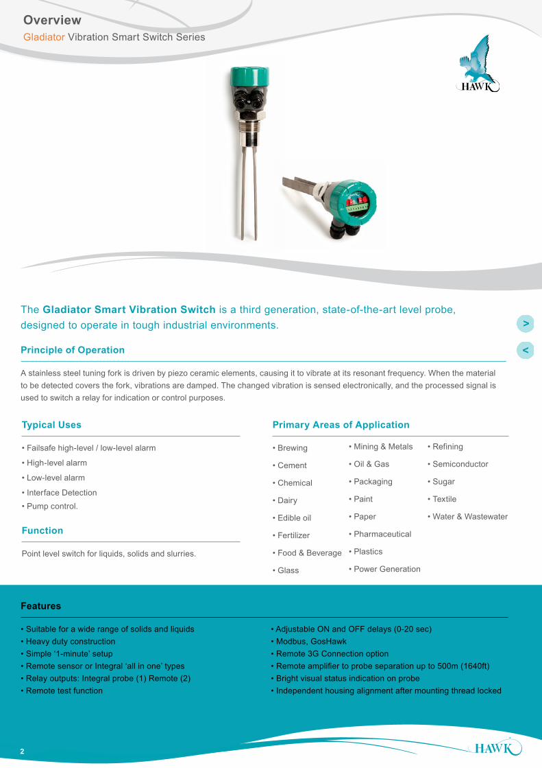
High and low liquid level switch in tanksLevel switch in liquid tank
Foam
Liquid
Low LevelVS1100
LIQUID / NO LIQUIDPROTECTION FOR PUMPSVS1100
High LevelVS1100
High / High LevelVS1200
Max.500m
(1640ft)
GSA Remote Amplifier
CAL
RUN
RELAY 1 RELAY 2 STATUS A STATUS B
VS1100
VS1100
VS1100
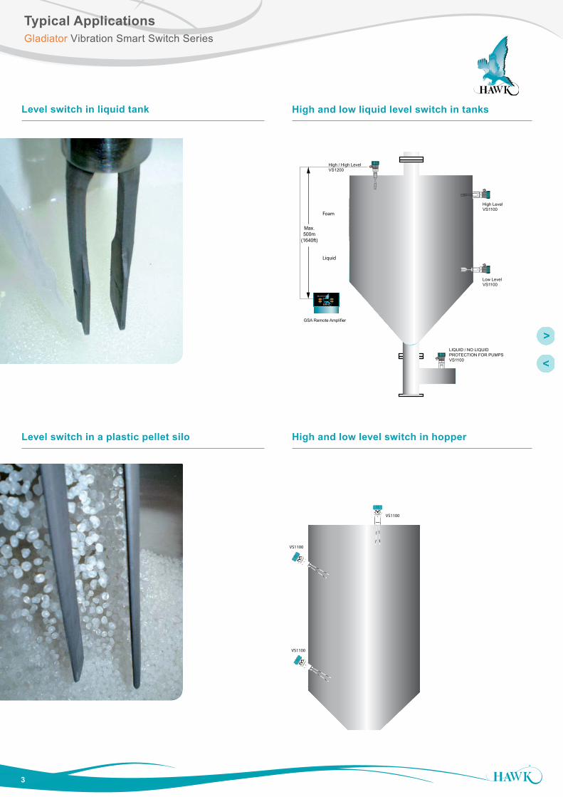
Level switch in a plastic pellet silo High and low level switch in hopper
Typical ApplicationsGladiator Vibration Smart Switch Series

OverviewGladiator Admittance Smart Switch Series
4
Overview
Dimensions
Remote Amplifier
Solid ProbesLiquid Probe
14 mm (0.6”)
74 mm (2.9”)
78 mm (3.1”)
107
mm
(4.2
”)
111.5 mm (4.4”)
4 mm (0.2”)
50 mm (2”)
131.
5 m
m (5
.2”)
7.5
mm
(0.3
”)
192.5 mm (7.6”)
141.
5 m
m (5
.6”)
190
mm
(7.5
”)
182.5 mm (7.2”)
147 mm (5.8”)
167.
5 m
m (6
.6”)
147 mm (5.8”)
30.7
mm
(1.2
”)
158 mm (6.2”)
108
mm
(4.3
”)
190
mm
(7.5
”)
174 mm (6.9”)192.5 mm (7.6”)
182.5 mm (7.2”)
30.0 20.2
33.029.029.033.0
16.2
Flange Dimensions - 50mm (2”)
A B C
ANSI (Class 150) 120.7 4.75” 152.4 6” 19.1 0.75”
DIN (PN40) 125 4.9” 165 6.5” 18 0.7”
JIS (10K) 120 4.7” 155 6.1” 19 0.75”
Gladiator Vibration Smart Switch Series
25m
m (1
”)
140m
m (5
.5”)
20mm (0.8”)
50m
m (2
”)
Thread 1" NPT/BSP
85mm (3.3”)Window for viewing status LEDs
90m
m (3
.5”)
50m
m (2
”)
2 x M20cable glandsor 3/4” NPT adaptors
Thre
ad 1
-1/2
" N
PT/
BS
P
85mm (3.3”)
M20 cable glandor 3/4” NPT adaptor
Window forviewing statusLEDs
90m
m (3
.5”)
50m
m (2
”)
4 mm (0.2”)
22 mm (0.9”)
25 m
m (1
”)
1000
/200
0/30
00/5
000
mm
(39.
4/78
.7/1
18.1
/196
.9”)
150
mm
(5.9
”)
SS 316
A BC
260/
500/
1000
mm
(10.
2/19
.7/3
9.4”
) Thre
ad 1
-1/2
" N
PT/
BS
P
85mm (3.3”)
M20 cable glandor 3/4” NPT adaptor
Windows for viewing status LEDs
90m
m (3
.5”)
50m
m (2
”)
4 mm (0.2”)
22 mm (0.9”)
25 m
m (1
”)
Temperature Extension Option
5
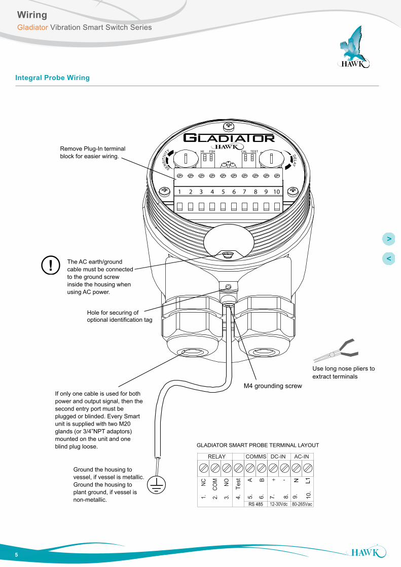
Integral Probe Wiring
1 2 3 4 5 6 7 8 9 10
SENSIT
IVIT
Y
DELAY
HI FSH TESTCAL
1.
NC
RELAY
2.
COM
3.
NO
COMMS DC-IN AC-IN
4.
Test
12-30Vdc 80-265Vac
+7.
8.
N9.
L110
.
RS 485
5.
B
6.
A -
GLADIATOR SMART PROBE TERMINAL LAYOUT
Hole for securing of optional identification tag
M4 grounding screw
Ground the housing to vessel, if vessel is metallic.Ground the housing to plant ground, if vessel is non-metallic.
The AC earth/ground cable must be connected to the ground screw inside the housing when using AC power.
If only one cable is used for bothpower and output signal, then the second entry port must be plugged or blinded. Every Smart unit is supplied with two M20 glands (or 3/4”NPT adaptors) mounted on the unit and one blind plug loose.
Remove Plug-In terminal block for easier wiring.
!
Use long nose pliers toextract terminals
WiringGladiator Vibration Smart Switch Series

6
Remote Probe to Amplifier Wiring
1 2 3 4 5 6 7 8 9 10
GLADIATOR REMOTE PROBE TERMINAL LAYOUT
M4 grounding screw
7. 1. 2. 3. 4. 5. 6. 8. 9. 10.
RED
WH
ITE
BLU
E
BLA
CK
Cable type between Amplifier and Probe4 conductor shielded twisted pair instrument cable.Conductor size dependent on cable length. BELDEN 3084A, DEKORON or equivalent.Max: BELDEN 3084A = 500m (1640 ft)Max: DEKORON IED183AA002 = 350m (1150 ft)
Hole for securing of optional identification tag
Ground the housing to vessel, if vessel is metallic.Ground the housing to plant ground, if vessel is non-metallic.
Terminals 1, 2, 3, 4, 9, 10 not used.
Gladiator Remote Amplifier
Relay 1 - Output RelayRelay 2 - FailSafe Relay
+ – A 1L+– NBRED
BLAC
K
BLUE
WHI
TE
BRO
WNIs
SENSOR DC-In AC-In*4-20mA (N/A) COMMS
MIC-SENDER
RED
BLA
CK
BR
OW
N
SLAV
E IN
MA
STER
OU
T
TEST
IN
RELAY 1
NC
CO
M
NO
RELAY 2
NC
CO
M
NO
1 2 3 4 5 6 7 8 9 10 11 12 13 14 15
16 17 18 19 20 21 22 23 24 25 26 27 28 29 30
Remove Plug-In terminal block for easier wiring.
Use long nose pliers toextract terminals
WiringGladiator Vibration Smart Switch Series
*AC-In is replaced by 36-60VDC with Power Input Option ‘C’.

7
Relay Functions
FailSafe LowFSL
1 2 3
1 2 3
1 2 3
1 2 3
FailSafe HighFSH (default)
1 2 3
1 2 3
1 2 3
1 2 3
RISING LEVEL(not detected)
CONTACT LEVEL(detected)
FALLING LEVEL(not detected)
NC NO
NC NO
NC NO
NC NO
NC NO
NC NO
NC NO
NC NO
COM COM
COM COM
COM COM
COM COMPOWER FAILURE
NC NO NC NOCOM COMINTERNAL FAILURE
POWER FAILURE
OR
SYSTEM OPERATING NORMALLY
NC NOCOM NC NOCOM
Stat
e 1
Stat
e 2
Stat
e 1
Smart Probe terminal numbers
Remote Amplifier terminal function labels
Relay Status
LED Status
Relay Action
Fail-Safe Switch Contact Action
Relay 2 - Remote version only.
For Integral Probes the ‘Test’ terminal can act as a solid state output with a similar function.
Level Switch Contact Action
Relay - for Integral Probe version
(Set Relay Action selection switch)
Relay 1 - for Remote version
(Set Relay Action parameter)
Relay FunctionsGladiator Vibration Smart Switch Series

8
Correct
Correct (non-preferred low level mounting)
Incorrect
Correct Correct
If necessary, mount aprotection plate to prevent direct impact.
Housing can be rotated within 200º after the mounting thread is tightened, to allow cableentries to face downwards or allow optimal cable clearance.
30-45º
Possible product build-up
Possible product build-up
Correct
Correct
Incorrect
Incorrect
Incorrect
Correct
Mounting
Probes can be mounted from above or from the side.
Use a protection plate for side mounting where the probe may be subject to impact damage.
Install the Probe far enough away from the vessel wall to prevent the forks from coming into contact with the wall, and prevent build-up of product between the forks and the wall over time.
Mounting ExamplesGladiator Vibration Smart Switch Series
9
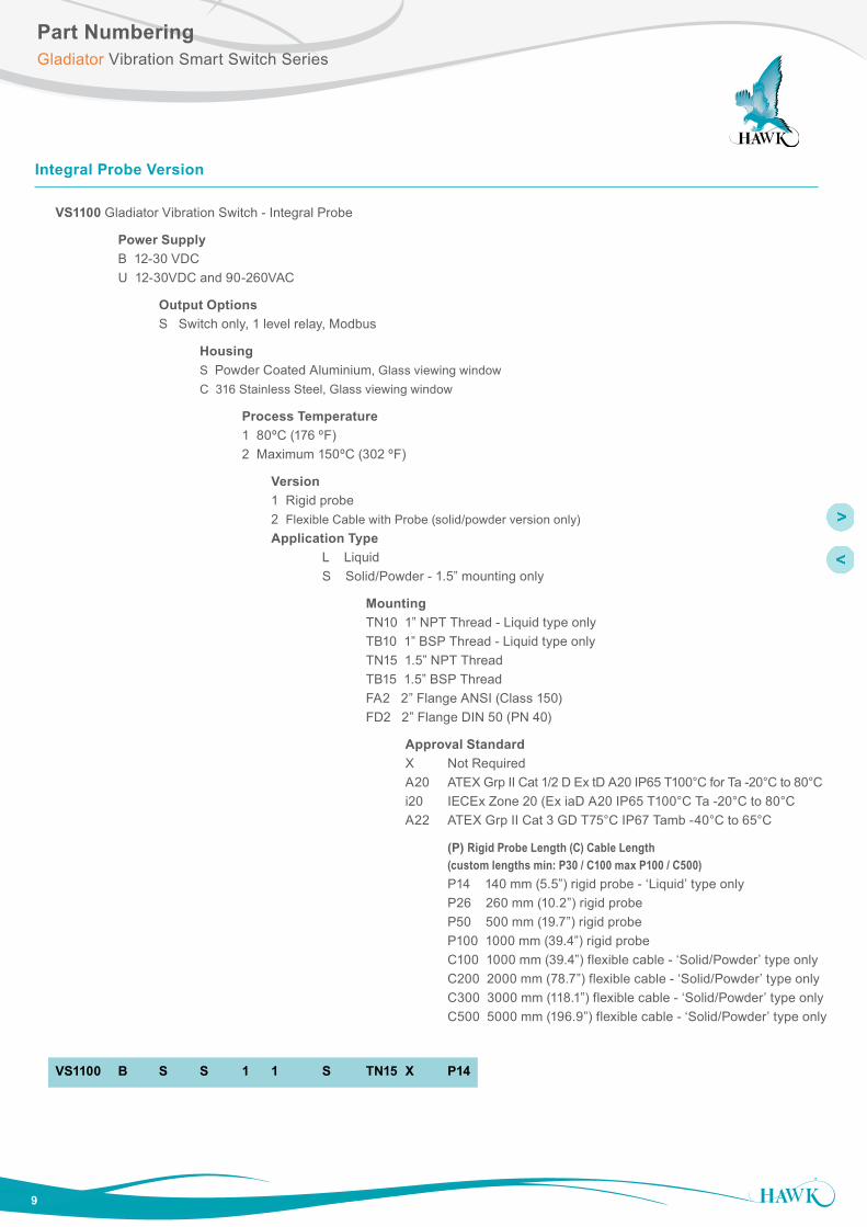
Integral Probe Version
VS1100 Gladiator Vibration Switch - Integral Probe
Power Supply B 12-30 VDC U 12-30VDC and 90-260VAC
Output Options S Switch only, 1 level relay, Modbus
Housing S Powder Coated Aluminium, Glass viewing window C 316 Stainless Steel, Glass viewing window
Process Temperature 1 80ºC (176 ºF) 2 Maximum 150ºC (302 ºF)
Version 1 Rigid probe 2 Flexible Cable with Probe (solid/powder version only) Application Type L Liquid S Solid/Powder - 1.5” mounting only
Mounting TN10 1” NPT Thread - Liquid type only TB10 1” BSP Thread - Liquid type only TN15 1.5” NPT Thread TB15 1.5” BSP Thread FA2 2” Flange ANSI (Class 150) FD2 2” Flange DIN 50 (PN 40)
Approval Standard X Not Required A20 ATEX Grp II Cat 1/2 D Ex tD A20 IP65 T100°C for Ta -20°C to 80°C i20 IECEx Zone 20 (Ex iaD A20 IP65 T100°C Ta -20°C to 80°C A22 ATEX Grp II Cat 3 GD T75°C IP67 Tamb -40°C to 65°C
(P) Rigid Probe Length (C) Cable Length (custom lengths min: P30 / C100 max P100 / C500) P14 140 mm (5.5”) rigid probe - ‘Liquid’ type only P26 260 mm (10.2”) rigid probe P50 500 mm (19.7”) rigid probe P100 1000 mm (39.4”) rigid probe C100 1000 mm (39.4”) flexible cable - ‘Solid/Powder’ type only C200 2000 mm (78.7”) flexible cable - ‘Solid/Powder’ type only C300 3000 mm (118.1”) flexible cable - ‘Solid/Powder’ type only C500 5000 mm (196.9”) flexible cable - ‘Solid/Powder’ type only
VS1100 B S S 1 1 S TN15 X P14
Part NumberingGladiator Vibration Smart Switch Series
10
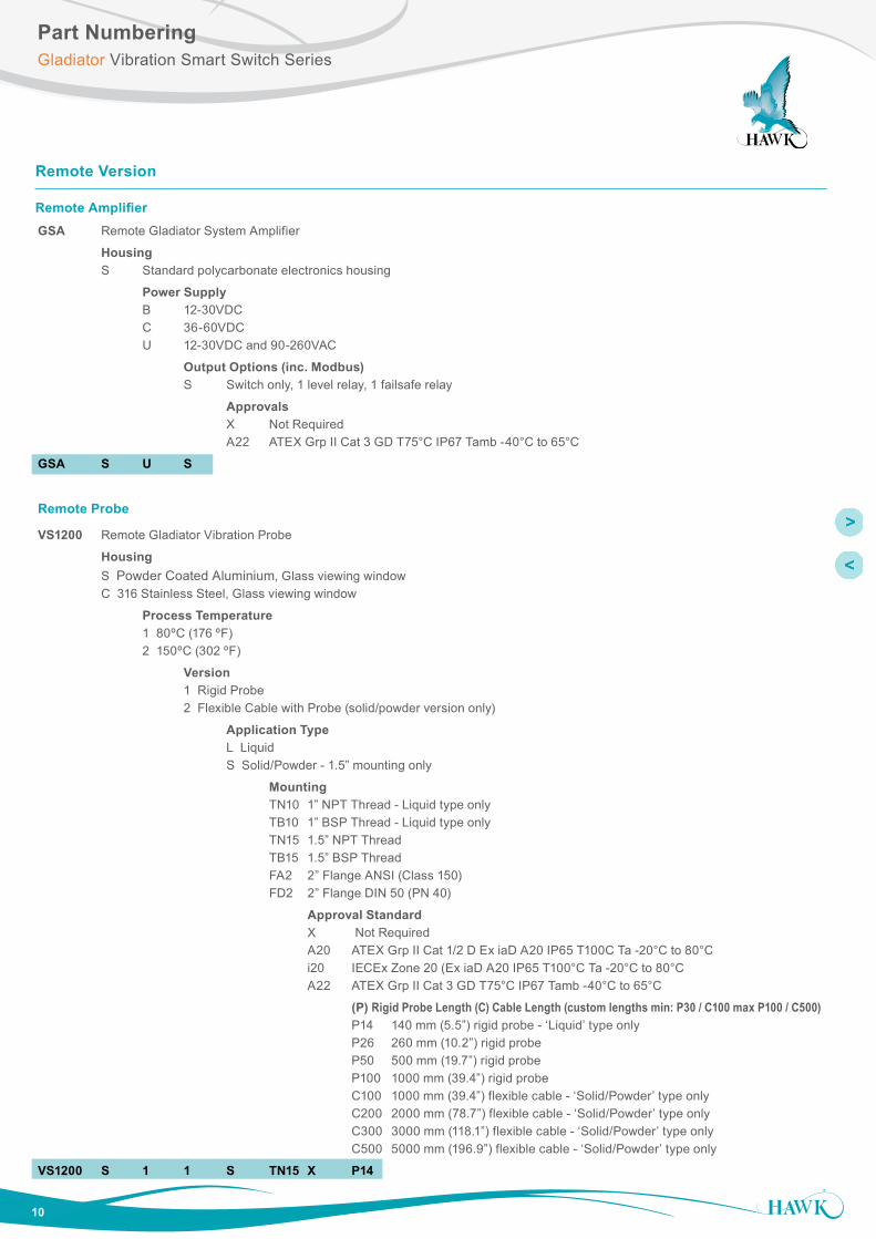
Remote Version
Remote AmplifierGSA Remote Gladiator System Amplifier
Housing S Standard polycarbonate electronics housing
Power Supply B 12-30VDC C 36-60VDC U 12-30VDC and 90-260VAC
Output Options (inc. Modbus) S Switch only, 1 level relay, 1 failsafe relay
Approvals X Not Required A22 ATEX Grp II Cat 3 GD T75°C IP67 Tamb -40°C to 65°C
GSA S U S
Remote Probe
VS1200 Remote Gladiator Vibration Probe
Housing S Powder Coated Aluminium, Glass viewing window C 316 Stainless Steel, Glass viewing window
Process Temperature 1 80ºC (176 ºF) 2 150ºC (302 ºF)
Version 1 Rigid Probe 2 Flexible Cable with Probe (solid/powder version only)
Application Type L Liquid S Solid/Powder - 1.5” mounting only
Mounting TN10 1” NPT Thread - Liquid type only TB10 1” BSP Thread - Liquid type only TN15 1.5” NPT Thread TB15 1.5” BSP Thread FA2 2” Flange ANSI (Class 150) FD2 2” Flange DIN 50 (PN 40)
Approval Standard X Not Required A20 ATEX Grp II Cat 1/2 D Ex iaD A20 IP65 T100C Ta -20°C to 80°C i20 IECEx Zone 20 (Ex iaD A20 IP65 T100°C Ta -20°C to 80°C A22 ATEX Grp II Cat 3 GD T75°C IP67 Tamb -40°C to 65°C
(P) Rigid Probe Length (C) Cable Length (custom lengths min: P30 / C100 max P100 / C500) P14 140 mm (5.5”) rigid probe - ‘Liquid’ type only P26 260 mm (10.2”) rigid probe P50 500 mm (19.7”) rigid probe P100 1000 mm (39.4”) rigid probe C100 1000 mm (39.4”) flexible cable - ‘Solid/Powder’ type only C200 2000 mm (78.7”) flexible cable - ‘Solid/Powder’ type only C300 3000 mm (118.1”) flexible cable - ‘Solid/Powder’ type only C500 5000 mm (196.9”) flexible cable - ‘Solid/Powder’ type only
VS1200 S 1 1 S TN15 X P14
Part NumberingGladiator Vibration Smart Switch Series

11
Operating Voltage
• 7 - 30VDC (residual ripple no greater than 100mV) • 80 - 265VAC 50/60Hz • 36-60VDC
Power Consumption
• <0.8W @ 24VDC • <6W @ 48VDC • <5VA @ 240VAC • <3VA @ 115VAC
Communications
• GosHawk, Modbus • Remote version also with HART, Profibus DP and DeviceNet (options) • Multidrop mode can address 1-250 units over 4 wires
Relay Output: (1) Integral (2) Remote
• Form ‘C’ (SPDT) contacts, rated 5A at 240Vac resistive • Remote failsafe test facility for one relay
Vibration Frequency
• Liquids 425Hz • Solids 80Hz
Measurement Capability
• Liquids - All liquids and many solids • Solids - Solids, powder and some liquids
Sensitivity
• Liquids - 50 g/l • Solids - 5 g/l
Stability
• 0.01% of reading / °C
Operating Temperature
• Remote electronics -40°C (-40°F) to 80°C (176°F) • Integral Probe -40°C (-40°F) to 150°C (302°F)* • Remote Probe -40°C (-40°F) to 150°C (302°F)*
Probe/Amplifier Separation
• Up to 500m (1640ft) using specified extension cable
Cable type between Amplifier and Probe
• 4 conductor shielded twisted pair instrument cable • Conductor size dependent on cable length • BELDEN 3084A, DEKORON or equivalent • Max: BELDEN 3084A = 500m (1640ft) • Max: DEKORON IED183AA002 = 350m (1150ft)
Maximum Operating Pressure
• 2 BAR
Display (Remote version only)
• 2 line x 12 character alphanumeric LCD • Backlight standard
Memory - Remote
• Non-Volatile (No backup battery required) • >10 years data retention
Enclosure Sealing
• Integral Probe IP67 • Remote Electronics IP65 (Nema 4x) • Remote Probe IP67
Cable Entries
• BSP process mounting: 2 x M20 Glands • NPT process mounting: 2 x 3/4” NPT threaded adaptors • Remote: 3 x 20mm (0.8”), 1 x 16mm (0.6”) knock outs
Mounting
• 1” NPT or BSP Thread - Liquid type only • 1.5” NPT or BSP Thread - Solid/Powder type only • 50mm (2”) Flange (ANSI, DIN or JIS patterns available)
Remote Test Input
• Press to test (used to check for malfunction of unit from remote position, PLC, SCADA etc)
SpecificationsGladiator Vibration Smart Switch Series
*Model dependent

All
com
pany
or p
rodu
ct n
ames
are
regi
ster
ed tr
adem
arks
or t
rade
mar
ks o
f the
ir re
spec
tive
owne
rs.
Hawk Measurement Systems(Head Office)15 - 17 Maurice Court Nunawading VIC 3131, AustraliaPhone: +61 3 9873 4750Fax: +61 3 9873 [email protected]
Hawk Measurement 96 Glenn StreetLawrence, MA 01843, USA
Phone: +1 888 HAWKLEVEL (1-888-429-5538)Phone: +1 978 304 3000Fax: +1 978 304 [email protected]
Represented by:
For more information and global representatives: www.hawkmeasure.comAdditional product warranty and application guarantees upon request. Technical data subject to change without notice.
DO
C-V
IBR
ATIO
N-D
AT v
1.1
06/
16
ContactGladiator Vibration Smart Switch Series