E: esonance-work esowrk 5May-20151-Editorial May2015
14
458 RESONANCE May 2015 Classroom In this section of Resonance, we invite readers to pose questions likely to be raised in a classroom situation. We may suggest strategies for dealing with them, or invite responses, or both. “Classroom” is equally a forum for raising broader issues and sharing personal experiences and viewpoints on matters related to teaching and learning science. An Experiment on Projectile Motion Amitabh Srivastava 1 M K Raghavendra 1 and K P Ramesh 2 1 Undergraduate Programme 2 Department of Physics Indian Institute of Science Bengaluru 560 012 Email: [email protected] Keywords Projectile motion, Arduino microcontroller, photogate tim- ers, kinematics experiment. A simple and inexpensive experimental setup for studying projectile motion using a low-cost projectile launcher and a microcontroller-based photogate timer is described. Using this setup, all three kinds of projectile motion (horizontal, oblique – ground to ground, and oblique – from a height) are studied. Introduction The motion of projectiles known to mankind since the times of Archimedes is an example of two-dimensional motion. This motion occurs in a vertical plane defined by the direction of launch. In the simplest case (when air resistance is neglected and motion occurs close to the surface of earth), the projected body experiences a uniform acceleration along the vertical direction and a uniform velocity along the horizontal direction. A study on projectile motion helps in a thorough understanding of the basic concepts in kinematics like accelerated motion, uniform motion, equations of motion and so on. Though most students are exposed to an extensive theoretical treatment, hardly any experiments are done. In recent times, some experimental kits on projectile motion have become available but they are too expensive to be affordable to most schools and colleges. In this article, a simple experimental
Transcript of E: esonance-work esowrk 5May-20151-Editorial May2015

458 RESONANCE May 2015
Classroom
In this section of Resonance, we invite readers to pose questions likely to be raised in a
classroom situation. We may suggest strategies for dealing with them, or invite responses,
or both. “Classroom” is equally a forum for raising broader issues and sharing personal
experiences and viewpoints on matters related to teaching and learning science.
An Experiment on Projectile Motion
Amitabh Srivastava1
M K Raghavendra1 and
K P Ramesh2
1Undergraduate Programme
2Department of Physics
Indian Institute of Science
Bengaluru 560 012
Email: [email protected]
Keywords
Projectile motion, Arduino
microcontroller, photogate tim-
ers, kinematics experiment.
A simple and inexpensive experimental setup for studying
projectile motion using a low-cost projectile launcher and a
microcontroller-based photogate timer is described. Using
this setup, all three kinds of projectile motion (horizontal,
oblique – ground to ground, and oblique – from a height) are
studied.
Introduction
The motion of projectiles known to mankind since the times of
Archimedes is an example of two-dimensional motion. This
motion occurs in a vertical plane defined by the direction of
launch. In the simplest case (when air resistance is neglected and
motion occurs close to the surface of earth), the projected body
experiences a uniform acceleration along the vertical direction
and a uniform velocity along the horizontal direction. A study on
projectile motion helps in a thorough understanding of the basic
concepts in kinematics like accelerated motion, uniform motion,
equations of motion and so on. Though most students are exposed
to an extensive theoretical treatment, hardly any experiments are
done. In recent times, some experimental kits on projectile motion
have become available but they are too expensive to be affordable
to most schools and colleges. In this article, a simple experimental
CLASSROOM
459RESONANCE May 2015
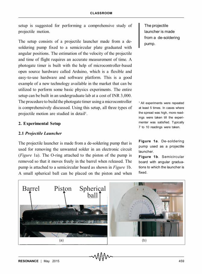
setup is suggested for performing a comprehensive study of
projectile motion.
The setup consists of a projectile launcher made from a de-
soldering pump fixed to a semicircular plate graduated with
angular positions. The estimation of the velocity of the projectile
and time of flight requires an accurate measurement of time. A
photogate timer is built with the help of microcontroller-based
open source hardware called Arduino, which is a flexible and
easy-to-use hardware and software platform. This is a good
example of a new technology available in the market that can be
utilized to perform some basic physics experiments. The entire
setup can be built in an undergraduate lab at a cost of INR 3,000.
The procedure to build the photogate timer using a microcontroller
is comprehensively discussed. Using this setup, all three types of
projectile motion are studied in detail¹.
2. Experimental Setup
2.1 Projectile Launcher
The projectile launcher is made from a de-soldering pump that is
used for removing the unwanted solder in an electronic circuit
(Figure 1a). The O-ring attached to the piston of the pump is
removed so that it moves freely in the barrel when released. The
pump is attached to a semicircular board as shown in Figure 1b.
A small spherical ball can be placed on the piston and when
1 All experiments were repeated
at least 5 times. In cases where
the spread was high, more read-
ings were taken till the experi-
menter was satisfied. Typically
7 to 10 readings were taken.
Figure 1a . De-soldering
pump used as a projectile
launcher.
Figure 1b . Semicircular
board with angular gradua-
tions to which the launcher is
fixed.
The projectile
launcher is made
from a de-soldering
pump.

CLASSROOM
460 RESONANCE May 2015
released, it can launch the ball with speed. The pump acts as a
projectile launcher. One end of the launcher is fixed to the center
of the board and the other end is supported by an L-clamp which
is free to move along the groove in the board. The launcher can be
placed at different angles by rotating it and the L-clamp helps in
securing it. The speed of the launch will depend on the spring
constant and the mass of the ball. By choosing balls of different
masses, the speed of launch can be changed. The semicircular
board can be attached to a stand and its height can be adjusted.
Thus, the height, angle and speed of the launch can be varied. This
helps in studying the dependence of range and time of flight of the
projectile on all these parameters.
2.2Microcontroller (Arduino)-based Photogate Timer
Arduino is a single-board microcontroller designed to make
interfacing with hardware and software easier. Arduino is based
on a free hardware and software concept, i.e., the hardware and
software details are freely available and any modification to
either is not only legally allowed but encouraged. The Arduino
programming software is freely available for various operating
systems. The Arduino board (Figure 2a) comes preloaded with a
boot-loader which allows the board to interface directly with a
computer. The board connects to the computer directly with a
USB cable.When connected, the computer can beused to program
the microcontroller as well as provide power to the board.
Arduino can be used to run low power devices such as LEDs and
LCD-panels (Figure 2b) directly. The board used in this project
has an Atmel 8-bit ARM microcontroller. It has 13 digital input/
output (IO) pins and 6 analog pins. The analog pins act as input
pins reading a voltage of up to 5V with a 10 bit resolution.
Because of the microcontroller used, the Arduino also provides
an internal clock which counts the microseconds since the last
reset. This clock has an accuracy of +0.05% and a resolution of 4
µs. This makes it ideal for use as a timer for externally triggered
events.
Arduino is based
on a free hardware
and software
concept.

CLASSROOM
461RESONANCE May 2015
2.3 Photogate
For measuring the speed of a projectile, a photogate is used. A
photogate is a device which produces an output (generally a
change in voltage) when an object cuts the path of a light beam in
the device. It is ideal for detecting moving objects without
interacting with them or changing their momentum. A photogate
consists of an infrared (IR) LED-detector pair (IR is used since
ambient IR noise is generally very low and it is cost effective).
The LED and the photodetector are set up directly opposite to
each other. When the projectile passes between the pair, the light
from the LED is cut off. The beam diameter is close to 1mm, so
any projectile larger than 1mm will register, when properly
centered.
The photodetector itself consists of a photodiode in series with a
large resistance (56K ) connected across a 5V source (Figure 3).
The photodiode acts as a photoresistor with a large resistance
when the IR light intensity is low and vice versa. In this case, the
output voltage is close to 3.5V when the beam is blocked and
close to 5V, otherwise. This voltage is fed to one of the analog
inputs of the Arduino.
A set of two photogates are mounted on the launcher with a
separation of x as shown in Figure 4. When a projectile passes
through the two photogates, the time taken to cross this distance
Figure 2a. Arduino compat-
ible single board microcon-
troller.
Figure 2b. LCD panel at-
tached to Arduino.
Figure 3. Photodetector.

CLASSROOM
462 RESONANCE May 2015
can be measured by noting the time duration ( t) between the two
triggering. The speed of the projectile is x/ t. The entire unit is
fixed in the front portion of the projectile launcher such that the
projectile passes through the photogate and hence its speed could
be recorded for every launch.
2.4 Contact Sensor
To measure time of flight of the projectile, two time sensors are
required; one at the point of projection and the other when it hits
the floor. The photogate, which is placed at the launcher, will
itself act as the first sensor. A contact sensor pad is used for the
second sensor. The contact sensor pad is basically a large plate
supported on a switch as shown in Figure 4. When an object falls
on the plate, the switch gets pressed due to the impact. The switch
itself is connected between 5V and a digital input pin of the
Arduino. Thus, the impact of an object changes the voltage at the
input pin which can be easily detected. This method is preferred
over other techniques such as piezoelectric sensors because it is
sensitive enough to be triggered just by theweight of the projectile.
2.5 Switches and Ports
The timer can also be used for other applications apart from
projectile motion. To select the required application, switches are
provided (Figure 5). By pressing the switch S1, the timer can be
used for the projectile motion experiment. In this case, the
Figure 4. Photogate sensor
attached to the launcher.
The contact sensor
pad is basically a
large plate
supported on a
switch.

CLASSROOM
463RESONANCE May 2015
velocity of launch and time of flight can be determined. Once
reading is taken, the reset switch is pressed for taking the next
reading. The photogates (attached to launcher and the contact
sensor pad) are connected to the microcontroller through USB
ports. The timer can also be used in simple pendulum and free fall
experiments. In this article, only the projectile motion experiment
is discussed.
2.6 Software
The software for this kit is written using theArduino programming
environment. The software already provides a clock function
which gives the number of microseconds since the start of the
microcontroller with 4 µs resolution. To time the duration of an
event, the software needs to note the clock time at the start of the
event and at the end of the event. The duration is simply the
difference of the two values. So, to measure the speed of the
projectile, the time when the first photogate is triggered is noted
and then the output of the second photogate is checked in a loop
(continuously, until the photogate is triggered). The time is noted
again and their difference gives the duration. The same concept
applies for finding the time of flight. Although the clock resolution
is 4 µs, the limiting step is reading the analog voltage output of the
photogates, which can only be done at 10KHz. Thus, the effective
time resolution is 0.1ms, which is comparable to the commercially
available timers.
Figure 5. Contact switch
mounted on a base on which
a plastic pad is anchored and
the Arduino setup is
placed in the box with swi-
tches and ports.
Theeffective time
resolution is
0.1ms, which is
comparable to the
commercially
available timers.

CLASSROOM
464 RESONANCE May 2015
3. The Experiment
In a projectile motion experiment, the horizontal range (R) and
time of flight (T) are some of the parameters of interest. In the
following experiment we explore the dependence of these
parameters on the initial conditions (speed, angle and height of
launch). Using the appropriate relations the value of g can also be
determined.
All three kinds of projectilemotion are studied using the projectile
launcher and photogate timer. The experiment on the horizontal
projectile is exploratory type. In the case of the ground-to-ground
projectile and oblique projectile from a height, experimental
results are compared with those predicted by theory.
3.1 Horizontal Projectile Motion
The projectile launched from a height in the horizontal direction,
as shown in Figure 6, is called a horizontal projectile. The range
of the projectile depends on the initial velocity u, the height h
from which the projectile is launched and g. The expression for R
can be written as
R = Kumhn , (1)
whereK,m and n are constants to be determined in the experiment.
The value of g is included in K.
The experiment is conducted in two parts.
In the first part, the height of the launch is fixed at 0.406mto study
the variation of range with respect to speed of launch. Different
speeds are obtained by taking spherical balls of different sizes and
material.
Figure 6. Schematic repre-
sentation of horizontal pro-
jectile.
All three kinds of
projectilemotion
are studied.
The experiment on
thehorizontal
projectile is
exploratory type.

CLASSROOM
465RESONANCE May 2015
The range is measured by placing a carbon sheet on the table
where the projectile hits. The horizontal distance between the
point of projection and the carbon mark is measured with a scale
of least count 1mm. Multiple trials in each case show the
uncertainty in measurement of range to be less than 3% and
uncertainty in measurement of velocity to be less than 2%. The
time of flight was found to be constant with 1% deviation.
The value of m can be determined by plotting the log of range
versus the log of velocity. The slope gives the value of m. The
graph is shown inFigure 7. Thevalue of 0.95 ± 0.04 indicates that
m is very close to unity which suggests that range is linearly
dependent on the velocity of the projectile.
In the second part, the variation of range with respect to height is
studied keeping the velocityof the projectile constant. The launcher
is placed at different heights and a spherical ball is launched. The
range is measured using the carbon sheet method. The experiment
is repeated with the same ball so that the speed of launch remains
the same. In order to explore the relation between R and h, a graph
of log R vs. log h is plotted. This is shown in Figure 8 along with
Figure 7. Graph of log R vs.
log u.
The range is
measured using
the carbon sheet
method.

CLASSROOM
466 RESONANCE May 2015
the value of the slope equal to 0.47 ± 0.02. This suggests that the
value of n is 0.5 and hence, R h.
The results of the above two parts can be combined to obtain the
value of K. Range (R) is plotted as a function of u h. The slope
of the straight line graph gives the value of K which is seen to be
0.46 ± 0.02 in SI units (Figure 9). Thus, the empirical relation for
range can be written as
huR 0.46 . (2)
The theoretically obtained expression for range is given by
.g
2=
huR
Here, g is the acceleration due to gravity. Comparing the two
expressions, the constant K can be expressed as
.2
gK
The value of g obtained using this expression is (9.3 ± 0.7) ms-2.
Good agreement in the value of g implies that the empirical
Figure 8. Graph of log R vs.
log h is shown along with the
value of n.
Good agreement
in the value of g
implies that the
empirical
expression for
range is indeed
correct.

CLASSROOM
467RESONANCE May 2015
expression for range given in equation (2) is indeed correct.
3.2 Oblique Ground to Ground Projectile
When a projectile launched from the ground reaches the same
horizontal level as its initial position, after its flight in air
(Figure 10), it is called a ground to ground projectile.
The range, R, and the time of flight, T, attained by the projectile
depend on the angle of projection, , and the velocity of launch,
u, given by
.sin2
=andcossin2
=2
g
uT
g
uR (3)
In the experiment, the variation of the horizontal range of the
projectile as a function of its angle of projection is studied. The
launcher is oriented at angles ranging from 10o to 80o in steps of
5o. As in the previous case, multiple trials were conducted for
each angle. The range was measured using the carbon sheet
method. When the launcher was oriented at an angle, care was
taken to ensure that the point of projection was at the same level
as that of the table. The data obtained was compared with the
Figure 9. Graph of R vs.
u h is shown along with the
value of slope.
Figure 10. Schematic rep-
resentation of ground-to-
ground projectile.

CLASSROOM
468 RESONANCE May 2015
theoretical estimation. The u measured in the experiment was
used for the theoretical calculations. The graph of range as a
function of angle is shown in Figure 11. The comparison between
values obtained from theory and the experiment is good in the
given range of angles. It can be observed that the maximum range
occurs at 45°. The graph of time of flight as a function of angle is
shown in Figure 12. An excellent agreement with theory is
observed.
Figure 11.Comparison ofex-
perimental and theoretical
values of R vs. ; ground to
ground projectile.
Figure 12.Comparison ofex-
perimental and theoretical
values of T vs ; ground to
ground projectile.
The comparison
between values
obtained from
theory and the
experiment is good

CLASSROOM
469RESONANCE May 2015
3.3 Oblique Projectile from a Height
The projectile motion as shown in Figure 13 can be analyzed by
considering vertical and horizontal motion independently. The
motion along the vertical direction can be described using the
equation:
.2
1sin 2gtuh(t) (4)
Here, t is the time of flight of the projectile. The motion along the
horizontal direction can be described using the equation,
.cos tuR (5)
Theoretically, the time of flight can be obtained by solving the
quadratic equation (4). Substituting for t, the range of the
projectile can also be estimated.
In the experiment, the launcher is placed at a height of 30cm. The
angle of launcher is changed from 10° to 80°. Each time, care is
taken to fix the point of projection at a height of 30 cm from the
ground. Multiple trials were conducted for each angle. The
variation of range with angle of projection is shown in Figure 14.
This is comparedwith the theoretical calculation of rangedescribed
the previous paragraph. A good agreement is observed. Figure 15
Figure 13. Schematic show-
ing oblique projectile from a
height.
Figure 14.Comparisonofex-
perimental and theoretical
values of R vs. ; oblique
projectile from a height.

CLASSROOM
470 RESONANCE May 2015
variation of time of flight with angle of projection. Again, a good
agreement is observed.
4. Results and Conclusion
1) The projectile launcher fabricated using a de-soldering pump
seems to provide a consistent initial velocity to the spherical ball.
The variation in the velocity of the steel ball used in most of the
experiments was found to be about 2%.
2) The photogate sensor along with the timer unit obtained from
Arduino is found to be precise and accurate. The time resolution
is around 0.1ms. The velocity has been determined to an accuracy
of 0.01m/s.
3) The empirical formula obtained in the case of horizontal
projectile motion agrees well with the theoretical expression.
Students should be made familiar with the exploratory type of
experiments. Without knowing the mathematical relation or the
theoretical basis, the dependenceof a physical quantity ondifferent
parameters can be determined by performing experiments. In the
development of physics, this method has led to the discovery of
many important phenomena.
Figure 15.Comparisonofex-
perimental and theoretical
values of T vs. ; oblique pro-
jectile from a height.
The photogate
sensor along with
the timer unit
obtained from
Arduino is found to
be precise and
accurate.
CLASSROOM
471RESONANCE May 2015
4) In the case of oblique projectile motion (ground-to-ground and
from a height), good agreement between experimentally
determined horizontal range and time of flight as functions of
angle of projection with theory gives confidence in the treatment
of 2D motion as two independent 1D motions. Further, the
assumptions of constancy of g and neglecting air resistance
appear to be correct.
5) This can be one of the experiments on kinematics of a body that
can be introduced in the undergraduate laboratory curriculum.
With the help of a photogate timer, other experiments like simple
pendulum, free fall, etc., can be studied more accurately.
6) More physics experiments using the microcontroller-based
open hardware platform are being explored.
This method has led
to the discovery of
many important
phenomena.