E ect of a new wet soot absorber on soot removal of a...
9
-
Upload
truongtuong -
Category
Documents
-
view
212 -
download
0
Transcript of E ect of a new wet soot absorber on soot removal of a...

Scientia Iranica B (2014) 21(3), 569{577
Sharif University of TechnologyScientia Iranica
Transactions B: Mechanical Engineeringwww.scientiairanica.com
E�ect of a new wet soot absorber on soot removal of adiesel engine
M. Ghazikhania, M.E. Feyza, I. Khazaeeb;1;�, A. Ghazikhania andM.J. Mahmoudzadeh Akherata
a. Department of Mechanical Engineering, School of Engineering, Ferdowsi University of Mashhad, Mashhad, P.O. Box 91775-1111,Iran.
b. Department of Mechanical Engineering, Torbat-e-jam Branch, Islamic Azad University, Torbat-e-jam, Iran.
Received 25 December 2011; received in revised form 25 September 2013; accepted 4 November 2013
KEYWORDSWet soot absorber;Diesel particulatematter;BSFC.
Abstract. In the following investigation, a submerged-type Wet Soot Absorber (WSA)is studied, and its capability to reduce the soot emission level of a four cylinder, DirectInjection (DI) diesel engine is evaluated. The WSA can provide a large contact area betweenwater and exhaust ow, which increases the soot capturing probability. Hence, the systemcan be more compact and suitable for vehicle engine applications. The ECE-R49 standardtest is followed to assess the e�ect of the WSA on engine performance and soot emission.The experiments revealed that a soot removal e�ciency of 70% is attained under full-loadengine operating conditions, due to the high momentum of exhaust gas ow entering thechamber of the unit and providing more ow penetration into the water. Also, furtherbubble break-up in high gas velocity results in a larger liquid-gas interface and contributesto better soot removal. The minor negative e�ects of utilizing the WSA on Brake Speci�cFuel Consumption (BSFC) are also compared with those of conventional DPFs, and theadvantages of WSA are discussed.© 2014 Sharif University of Technology. All rights reserved.
1. Introduction
During the last decade, diesel engines have attractedextensive attention in transportation industries andredirected the preference of automotive manufacturers,due to their high thermal e�ciency and rather lowfuel costs [1]. However, there are some concernsregarding the emissions of Compression Ignition (CI)engines, restricting their worldwide application. Dieselengines produce signi�cant amounts of nitrogen oxidesand soot compared to the conventional spark ignitionengines [2,3]. Nitrogen oxides, known as NOx, have
1. Present address: Faculty of Mechanical and EnergyEngineering, Shahid Beheshti University, A.C., Tehran,Iran.
*. Corresponding author. Tel: +98 9153063878;Fax: +98 511 8763304E-mail address: [email protected] (I. Khazaee)
long been considered a serious threat to human health,and the hazard to the human body of emitted sootfrom diesel engines has been recently evaluated sys-tematically. Soot e�ects on climate change and theenvironment are also addressed in the literature [4,5].Actually, engine combustion improvement and modi�-cation of fuel structures have a great signi�cance in thesuppression of soot and Particulate Matter (PM) (4) [6-11]. According to available studies, in-cylinder param-eters, such as fuel injection pressure, injection timing,spray geometry, air/fuel swirl ratio, turbo-charging,combustion chamber shape, wall temperatures and Ex-haust Gas Recirculation (EGR), seem to play a criticalrole in terms of controlling diesel combustion emissions.Another approach which contributes to the emissionrestriction of diesel engines is utilizing alternative fuels.Fuel additives and bio fuels provide a rather promisingresolution for emission suppression in diesel engines [12-

570 M. Ghazikhani et al./Scientia Iranica, Transactions B: Mechanical Engineering 21 (2014) 569{577
17]. However, the strict emission regulations appliedto diesel engines urge the necessity of utilizing after-treatment devices to capture soot and PM containedin engine exhaust. Diesel Particulate Filters (DPFs)and Selective Catalytic Reduction (SCRs) have beenrecently developed to maintain the level of emittedsoot under a reasonable level in the CI engine [18-20],while the removal e�ciency of these after-treatmentdevices has been proven up to 99% [21]. Dependingon �lter type and age, engine size, sampling methods,and fed fuel [22,23], using DPFs and SCRs imposesextensive problems including their regeneration andrenewal requirements. For instance, in one of the mostrecent surveys, Dilip et al. [24] studied heating tech-niques for the regeneration of a stainless-steel mesh-type particulate �lter. Their theoretical estimationshows that the induction heating approach for regen-eration via exhaust gas heating requires high power(> 3 kW). Moreover, one of the serious challengesthat DPFs face is the inevitable pressure drop inthe exhaust route, which leads to an increase in theengine pumping work and causes additional speci�c fuelconsumption [25,26]. Similarly, common defects withSCRs appear to be their limited temperature operationcircumstances, the small residence time of the exhaustgas, catalyst poisoning, ammonia leakage and thedischarge of catalyst mass under high temperature con-ditions, which circumscribe their application [27-29].Due to the drawbacks associated with utilization of theabove techniques, some new approaches are employedto trap diesel particulate matter. A traditional groupof these methods are based upon particle inertia andis known as cyclonic particulate �ltration. Arcouma-nis et al. [30] developed a cyclone-based particulatetrap for an EGR-equipped, high-speed diesel engine.With the help of enhanced particulate agglomerationprovided by a cooling heat exchanger system, theauthors reported a removal e�ciency of up to 77%.Another method uses electrostatic forces to capturethe particulates that are highly electrically charged.Several researchers have worked on the electrostaticagglomeration of aerosols produced by diesel enginesfor automotive applications [31,32]. Saiyasitpanichet al. [33] enhanced the PM removal ability of theconventional electrostatic agglomerators by combiningthe electrostatic e�ect with the e�ect of a wet surfacein capturing diesel particulate matter. The designbene�ts from the adhesion occurring in the solid-liquidinterface, which happens on the wet wall surface of atubular chamber, to trap soot particles. The aboveprecipitator was evaluated on a non-road electricitygenerator diesel engine. There are various advantagesof this method, including low maintenance costs, slightbackpressure, plain operation and the ability to collectrecycled soot. Also, Carotenuto et al. [34] developeda mathematical model to assess the particle removal
e�ciency in wet electrostatic scrubbers. The use ofexhaust gas washing to reduce diesel exhaust emissionsof a stationary diesel engine was lately pursued by Royet al. [35]. They bene�ted from the ability of water toabsorb exhaust soluble gas components, such as whitesmoke, NOx, CO and CO2, to reduce the exhaust odor.Also, a signi�cant reduction of 85% in black smokeemission is observed in their work. In spite of therather high smoke reduction e�ciency, the large sizeof their apparatus makes it di�cult to be implementedon vehicle diesel engines. Roy et al. employed a 2.75 m-long washing tower in order to purify the exhaust smokeof a single-cylinder, 4.47 kW, stationary diesel engine.
In the present study, a new design for a wet sootabsorber has been experimentally investigated on adiesel engine. In the proposed WSA, the downward gas ow from the exhaust pipe submerged into the waterprovides an extended gas-liquid interface that canimprove the removal of diesel particulate matter. Thisdesign can provide the chance for WSAs to be mountedon non-stationary diesel engines in automotive indus-tries due to its compactness and mobility. E�ectsof the wet soot absorber on removal e�ciency andBrake Speci�c Fuel Consumption (BSFC) in a typicalDI-diesel engine were also evaluated and the resultscompared with those of a recent study concerningcommon soot removal technologies.
2. Test setup
2.1. Diesel engine test benchThe schematic drawing of the test bed in Figure 1shows the OM314- DI diesel engine, the speci�cationsof which are presented in Table 1. The engine is coupledto a hydraulic DDX Heenan & Froude dynamometerto vary the engine load. A commercial diesel fuel wasused in all the tests. To measure the intake air ow, anori�ce-�tted surge tank is employed. Also, a computer
Table 1. Test engine speci�cations.
Engine type Compression ignition(naturally aspirated)
Number of cylinders 4Combustion chamber Direct injectionPiston shape Bowl-in shapedBore � stroke (mm) 97� 128Piston displacement (cc) 3784Compression ratio 17:1Maximum power (h.p) 85Maximum torque (N.m) 235Maximum speed (rpm) 2800Mean e�ective pressure (bar) 6.8@2800 rpmInjection pressure (bar) 240

M. Ghazikhani et al./Scientia Iranica, Transactions B: Mechanical Engineering 21 (2014) 569{577 571
Figure 1. Test bed components.
Table 2. Accuracy of measurement devices.
Device Error (%) Unit
Pressure gauge 1 mmHg
Thermocouple 0.01 �CDynamometer 1 N.m
Speed meter 0.1 rpm
Flow meter 1 Lit/min
Smoke meter 0.01 gr/cm3
interface unit is provided to measure the temperatureof inlet air at the ori�ce and the exhaust gases enteringand exiting the WSA, utilizing K-type thermocouples.Soot particulate mass concentration was recorded forevery test step with an AVL-415 smoke meter, whichcould also measure the exhaust opacity by Flow SootNumber (FSN). In its system, after the �lter paper isexposed to the exhaust ow sample, the bulb illumi-nates the �lter paper via a light guide. The re ectedlight, which depends on paper blackness, is registeredby means of a photodiode. At the beginning of eachtest series, the smoke meter was calibrated taking thesmoke content of the surrounding environment as thereference. The accuracy of measurement devices isavailable in Table 2.
2.2. WSA characteristics and modi�cationsThe investigated WSA comprises a rectangular cham-ber, 60, 30 and 60 centimeters in length, width andheight, respectively, constructed using a galvanizedmetal sheet, to which the 2 in exhaust pipe withraw exhaust is introduced and from which the treatedexhaust leaves. The chamber is �lled with water to30 centimeters and supported by a couple of ba�es to
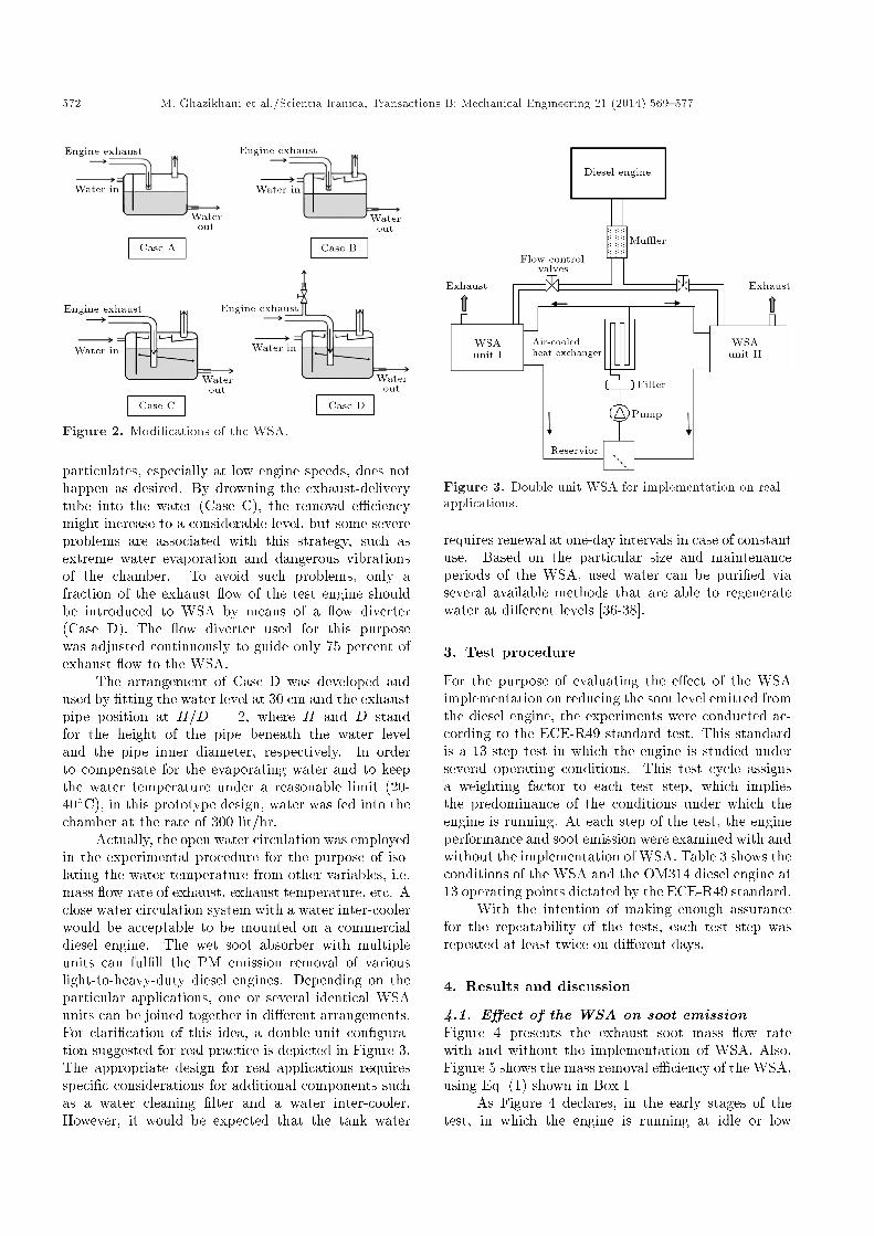
prevent water from over splashing or high waviness.The ba�es arrangement was developed during theproject and required several trial-and-error experi-ments to assure the ba�es reliability in preventingwater from producing unrestrained waves. All con-nections and edges were sealed with a silicon pastethat could tolerate temperatures exceeding 350�C.The soot removal process is based on the interactionoccurring between the exhaust ow and water, throughwhich the soot particles contained in the exhaust owstick to the water surface. Various mechanisms areengaged in the process of separating soot particles fromthe exhaust gases in the wet absorber. Tremendoussplashing caused by exhaust ow can enhance themixing of the exhaust ow and water, which improvesthe gas-liquid encounter. Also, the gas void fraction,which is dependent on the average gas velocity, playsa critical role in terms of changing the gas-liquidinterface area. Moreover, the cooling and expandingof the exhaust ow along the wet passage through theabsorber can increase the chance of soot deposition,due to the increase in ow density and the resultingreduction of ow velocity. Several con�gurations,i.e. the adjustment of the entering pipe position,with respect to the water surface and location of theba�es, have been tested to come up with an optimumdesign that could guarantee the best soot removale�ciency and simultaneously retain the stillness ofwater inside the chamber. Figure 2 represents fourdi�erent arrangements of introducing the exhaust gas ow of the diesel engine to the WSA. In the �rst case(Case A), the absence of ba�es allowed a signi�cantwater leakage from the exit pipe, which caused smokemeter failure. In Case B, because of inappropriatemixing and lack of splashing, the removal of soot and
572 M. Ghazikhani et al./Scientia Iranica, Transactions B: Mechanical Engineering 21 (2014) 569{577
Figure 2. Modi�cations of the WSA.
particulates, especially at low engine speeds, does nothappen as desired. By drowning the exhaust-deliverytube into the water (Case C), the removal e�ciencymight increase to a considerable level, but some severeproblems are associated with this strategy, such asextreme water evaporation and dangerous vibrationsof the chamber. To avoid such problems, only afraction of the exhaust ow of the test engine shouldbe introduced to WSA by means of a ow diverter(Case D). The ow diverter used for this purposewas adjusted continuously to guide only 75 percent ofexhaust ow to the WSA.
The arrangement of Case D was developed andused by �tting the water level at 30 cm and the exhaustpipe position at H=D = 2, where H and D standfor the height of the pipe beneath the water leveland the pipe inner diameter, respectively. In orderto compensate for the evaporating water and to keepthe water temperature under a reasonable limit (20-40�C), in this prototype design, water was fed into thechamber at the rate of 300 lit/hr.
Actually, the open water circulation was employedin the experimental procedure for the purpose of iso-lating the water temperature from other variables, i.e.mass ow rate of exhaust, exhaust temperature, etc. Aclose water circulation system with a water inter-coolerwould be acceptable to be mounted on a commercialdiesel engine. The wet soot absorber with multipleunits can ful�ll the PM emission removal of variouslight-to-heavy-duty diesel engines. Depending on theparticular applications, one or several identical WSAunits can be joined together in di�erent arrangements.For clari�cation of this idea, a double-unit con�gura-tion suggested for real practice is depicted in Figure 3.The appropriate design for real applications requiresspeci�c considerations for additional components suchas a water cleaning �lter and a water inter-cooler.However, it would be expected that the tank water
Figure 3. Double-unit WSA for implementation on realapplications.
requires renewal at one-day intervals in case of constantuse. Based on the particular size and maintenanceperiods of the WSA, used water can be puri�ed viaseveral available methods that are able to regeneratewater at di�erent levels [36-38].
3. Test procedure
For the purpose of evaluating the e�ect of the WSAimplementation on reducing the soot level emitted fromthe diesel engine, the experiments were conducted ac-cording to the ECE-R49 standard test. This standardis a 13-step test in which the engine is studied underseveral operating conditions. This test cycle assignsa weighting factor to each test step, which impliesthe predominance of the conditions under which theengine is running. At each step of the test, the engineperformance and soot emission were examined with andwithout the implementation of WSA. Table 3 shows theconditions of the WSA and the OM314 diesel engine at13 operating points dictated by the ECE-R49 standard.
With the intention of making enough assurancefor the repeatability of the tests, each test step wasrepeated at least twice on di�erent days.
4. Results and discussion
4.1. E�ect of the WSA on soot emissionFigure 4 presents the exhaust soot mass ow ratewith and without the implementation of WSA. Also,Figure 5 shows the mass removal e�ciency of the WSA,using Eq. (1) shown in Box I.
As Figure 4 declares, in the early stages of thetest, in which the engine is running at idle or low

M. Ghazikhani et al./Scientia Iranica, Transactions B: Mechanical Engineering 21 (2014) 569{577 573
Table 3. Working conditions of WSA under di�erent engine loads and speeds.
Testno.
Exhaust temp.before WSA
(�C)
Exhaust temp.after WSA
(�C)
Exhaustmomentum
(Ns)
WSA watertemperature
(�C)
Engineload
(N.m)
Enginespeed(rpm)
Weightingfactor
1 75.14 21.6 0.28 21 � 0 800 0.0662 122.13 28.8 0.84 23 18 1800 0.083 148.16 32.9 0.91 25 45 1800 0.084 197.91 38.7 1.04 27 90 1800 0.085 253.8 42.6 1.18 29 135 1800 0.086 338.9 46.7 1.40 35 180 1800 0.087 108.3 33 0.33 38 � 0 800 0.0668 451.8 50.8 3.07 40 160 2800 0.089 403.4 52.4 2.79 36 120 2800 0.0810 330.5 51.3 2.42 37 80 2800 0.0811 258.2 48.3 2.10 41 40 2800 0.0812 218.5 46.8 1.93 48 16 2800 0.0813 92.1 31.3 0.26 42 � 0 800 0.066
�removal = 100� Exhaust soot mass ow without WSA� Exhaust soot mass ow with WSAExhaust soot mass ow without WSA
: (1)
Box I
Figure 4. The variations of exhaust soot mass ow withand without WSA.
Figure 5. Simultaneous presentation of soot removale�ciency (N) and entering exhaust momentum (�).
loads of 1800 rpm and the lean combustion regime isprevailing (points 1, 2 and 3), the soot content of theexhaust is inconsiderable. Also, Figure 5 shows thatthe e�ect of the WSA in reducing the soot content ofthe exhaust gases is not satisfying at the early points.This might be due to the insu�cient momentum of theexhaust gases, which cannot provide enough exhaustgas penetration into the water for soot removal. Thesame fact also rules for idle conditions of points 7and 13. The gas momentum at each operating pointis calculated as the multiplying of exhaust mass owby exhaust ow velocity. The mass ow rate is asummation of intake air mass and injected fuel mass.Considering the exhaust gases as an ideal gas mixture,and by having exhaust pressure, temperature, mass ow and gas constant, the exhaust volumetric owand, hence, the exhaust velocity, can be obtained.According to the ideal gas state equation and measuredexhaust temperature, the exhaust ow velocity couldbe estimated. The exhaust momentum calculation ispresented via Eqs. (2) and (3):
Exhaust momentum = ( _mfuel + _mair)� VExh; (2)
VExh =( _mfuel + _mair)�Rmixture � TExh
PExh
1Atube
: (3)
In Eqs. (2) and (3), _mfuel and _mair represent the

574 M. Ghazikhani et al./Scientia Iranica, Transactions B: Mechanical Engineering 21 (2014) 569{577
fuel and mass ow rate, respectively. Exhaust velocity(VExh) is also calculated via the equation of state,Eq. (3), where Rmixture is equal to air gas constant andTExh and PExh are exhaust temperature and pressure,respectively. Finally, Atube is the exhaust tube cross-section area.
For points 4, 5 and 6, at which the momentumof exhaust gases is increasing, the comparison betweenraw and treated exhaust gases in Figure 4 clearly showsthe growing e�ectiveness of the WSA in trapping sootparticles. This lies within the fact that the appropriatemixing, followed by high velocity exhaust gases, canincrease the chances of collision between soot particlesand water. The same trend is observed in Figure 5in which the removal e�ciency is improved by theincrease of exhaust momentum. Since the momentumof gas ow attains a high level at Stage 8, greatremoval performance is observed at this point. Theincrease of soot removal, followed by the increase of gasmomentum, can also be interpreted as follows: bubblediameter decreases with super�cial gas velocity [39,40],which is due to the increased bubble breakup at highergas ow rates, creating a greater number of smallerbubbles. Hence, by extending the gas-liquid interface,enhanced soot removal can be expected.
The di�erence between the variations of removale�ciency and exhaust momentum during test points8 to 10 can possibly be caused by the rising watertemperature of the tank, which could make up for thelow momentum gas e�ect in absorbing exhaust PM.Continuing the test stages at 2800 rpm (from point 10up to 12), it is observed in Figure 5 that by reducingengine load, soot removal gradually declines, due toreduced exhaust momentum.
The results declared that when the engine isrunning under high load conditions, where smoke issigni�cantly produced, the WSA performs at its bestin reducing the soot level. In order to examine therepeatability of the results, the tests were repeatedtwice on di�erent days, and the removal e�ciency inboth test series had acceptable agreement.
4.2. E�ect of the WSA on BSFCFigure 6 displays the e�ect of the implementation ofWSA on Brake Speci�c Fuel Consumption (BSFC) fordi�erent testing points. The dominant issue in this�gure is the increase of BSFC caused by setting up theWSA, which generally imposes extra backpressure inthe exhaust route. Therefore, the engine must provideextra p-V work to overcome the increased exhaustmanifold pressure. Thus, the extra work required willresult in higher fuel consumption.
At test points 5 and 8, which are located athigh load conditions, a slight improvement of BSFCis observed by the implementation of WSA. It canbe probably explained via the noticeable e�ect of
exhaust backpressure on cylinder residual mass accu-mulation under high load operating conditions [41].The increase of in-cylinder residual mass can provideappropriate conditions for auto-ignition and, hence,shorten the combustion delay by providing high tem-perature surroundings [42]. Therefore, under suchconditions, the contribution of excess backpressurein shortening the combustion delay virtually o�setsthe negative e�ects of backpressure on speci�c fuelconsumption.
The superiority of the wet absorbers over con-ventional DPFs in vehicle diesel engines is highlightedthrough their minor e�ect on increasing BSFC. For thesake of clarity, the present experimental results of thee�ect of WSA on the increase of BSFC are comparedwith those of a study concerning the e�ect of usingDPFs on the increase of diesel fuel consumption [26].The comparison is established for low and high enginespeeds and is depicted in Figure 7. In Figure 7, the
Figure 6. The variations of engine BSFC with andwithout WSA.
Figure 7. Comparison of BSFC increase a�ected byinstallation of soot agglomeration devices.

M. Ghazikhani et al./Scientia Iranica, Transactions B: Mechanical Engineering 21 (2014) 569{577 575
investigated WSA is compared with two conventionaltypes of DPFs: cordierite DPF (Cd) and AcicularMullite DPF (ACM) in terms of their impact on theincrease of speci�c fuel consumption. In fact, thecolumn with the checker pattern represents the averagepercentage of WSA e�ect (either positive or negative)on engine BSFC for each speed. Since the increaseof exhaust backpressure in a WSA is lower comparedto conventional DPFs, a WSA essentially has slightere�ect on increasing the BSFC.
5. Conclusion
An experimental study was performed to evaluate thee�ect of a wet soot absorber on reducing the sootemission of a four-cylinder, DI-diesel engine. The testconditions were determined according to the ECE-R49test cycle. The results revealed that soot removale�ciency occurs best (� 70%) under conditions inwhich the exhaust ow penetrates further into thewater and improved mixing occurs between gas andliquid phases. Moreover, the intense bubble break-up, which happens at high gas velocities, can increasethe contribution to the particle separation processunder high load operating conditions. The comparisonbetween e�ects of the proposed WSA and conventionalDPFs on increasing speci�c fuel consumption provesthe advantage of a WSA over a DPF. This studycon�rmed the great potential of wet absorbers foragglomeration of diesel particulate matter. Although aremoval e�ciency of 70% is attained under particularengine operating conditions, higher e�ciency is ex-pected by improving the design parameters of the WSAapparatus. Since our current design of WSA is still pre-mature for development by being mounted on a vehiclediesel engines, it is suggested for prospective studiesto be concerned about issues such as the performanceof a WSA in transient engine operation, increasingthe exhaust-water interaction area by changing thegeometry of the exhaust gas distributor, and avoidinga partial mist forming in the exhaust gases after beingtreated by WSA.
Acknowledgment
The authors would like to thank the research division ofFerdowsi University of Mashhad for �nancing the cur-rent study, and Mr. D. Husseinzadeh for his technicaladvice.
References
1. Zheng, M., Reader, G.T. and Hawley, G. \Dieselengine exhaust gas recirculation-a review on advancedand novel concepts", Journal of Energy Conversionand Management, 45, pp. 883-900 (2004).
2. Martirosyan, K.S., Chen, K. and Luss, D. \Behaviorfeatures of soot combustion in diesel particulate �lter",Journal of Chemical Engineering Science, 65, pp. 42-46 (2010).
3. Hountalas, D.T., Mavropoulos, G.C. and Binder, K.B.\E�ect of exhaust gas recirculation (EGR) tempera-ture for various EGR rates on heavy duty DI dieselengine performance and emissions", Journal of Energy,33, pp. 272-283 (2008).
4. HEI \Understanding the health e�ects of componentsof the PM mix: Progress and next steps", HEIPerspectives, Boston, MA: Health E�ects Institute(2002).
5. HEI \Revised analyses of time-series studies of airpollution and health", Special Report, Boston, MA:Health E�ects Institute (2003).
6. Wang, X., Huang, Z., Zhang, W., Kuti, O.A. andNishida, K. \E�ects of ultra-high injection pressureand micro-hole nozzle on ame structure and sootformation of impinging diesel spray", Applied Energy,88, pp. 1620-1628 (2011).
7. Prasad, B.V.V.S.U., Sharma, C.S., Anand, T.N.C. andRavikrishna, R.V. \High swirl-inducing piston bowls insmall diesel engines for emission reduction", AppliedEnergy, 88, pp. 2355-2367 (2011).
8. Saravanan, N. and Nagarajan, G. \Performance andemission studies on port injection of hydrogen withvaried ow rates with diesel as an ignition source",Applied Energy, 87, pp. 2218-2229 (2010).
9. Minghai, L., Hongjiang, C., Juan, W. and Ying, G.\Improvement of fuel injection system of locomotivediesel engine", Journal of Environmental Sciences, pp.139-141 (2009).
10. Mallamo, F., Badami, M. and Millo, F. \E�ect ofcompression ratio and injection pressure on emissionsand fuel consumption of a small displacement commonrail diesel engine", SAE paper no. 2005-01-0379 (2005).
11. Uekusa, T. \Emission reduction study for meeting newrequirements with advanced diesel engine technology",SAE paper no. 2005-01-2143 (2005).
12. Rakopoulos, D.C., Rakopoulos, C.D., Kakaras, E.C.and Giakoumis, E.G. \E�ects of ethanol-diesel fuelblends on the performance and exhaust emissions ofheavy duty DI diesel engine", Energy Conversion andManagement, 49, pp. 3155-3162 (2008).
13. Rakopoulos, D.C., Rakopoulos, C.D., Giakoumis, E.G.and Dimaratos, A.M. \Investigation of the combustionof neat cottonseed oil or its neat bio-diesel in aHSDI diesel engine by experimental heat release andstatistical analyses", Fuel, 89, pp. 3814-3826 (2010).
14. Xiaoyan, S., Yunbo, Y., Hong, H., Shijin, S., Hongyi,D. and Rulong, L. \Combination of biodiesel-ethanol-diesel fuel blend and SCR catalyst assembly to reduceemissions from a heavy-duty diesel engine", Journal ofEnvironmental Sciences, 20, pp. 177-182 (2008).

576 M. Ghazikhani et al./Scientia Iranica, Transactions B: Mechanical Engineering 21 (2014) 569{577
15. Arima, T., Obata, K., Cao, G., Ogawa, H. andMiyamoto, N. \Improvements to diesel combustionand emissions by oxygenated agent addition to dieselfuels in uence of diesel fuels and oxygenated agentproperties", Proceedings of JSAE, paper 9637483, pp.269-272 (1996).
16. Roy, M., Tsunemoto, H. and Ishitani, H. \E�ect ofMTBE and DME on odorous emissions in a DI dieselengine", JSME Int. J. Ser. B, 43, pp. 511-517 (2000).
17. Hilden, D., Crellin, C., Toner, J. and Wolf, L. \Theexhaust emissions of prototype ultra-low sulfur andoxygenated diesel fuels", SAE paper no. 2005-01-3880(2005).
18. Yang, J., Stewart, M., Maupin, G., Herling, D.and Zelenyuk, A. \Single wall diesel particulate �lter(DPF) �ltration e�ciency studies using laboratorygenerated particles", Chemical Engineering Science,64, pp. 1625-1634 (2009).
19. Tente, H., Gomes, P., Ferreira, F., Amorim, J.H.,Casc~ao, P., Miranda, A.I., Nogueira, L. and Sousa, S.\Evaluating the e�ciency of diesel particulate �ltersin high-duty vehicles: Field operational testing inPortugal", Atmospheric Environment, 45, pp. 2623-2629 (2011).
20. Liu, J., Xu, J., Zhao, Z., Duan, A., Jiang, G. andJing, Y. \A novel four way combining catalysts forsimultaneous removal of exhaust pollutants from dieselengine", Journal of Environmental Sciences, 22, pp.1104-1109 (2010).
21. Bergmann, M., Kirchner, U., Vogt, R. and Benter, T.\On-road and laboratory investigation of low-level PMemissions of a modern diesel particulate �lter equippeddiesel passenger car", Journal of Atmospheric Environ-ment, 43, pp. 1908-1916 (2009).
22. Baz-Dresch, J., Bickel, K.L. and Watts, W.F., Eval-uation of Catalyzed Diesel Particulate Filters in anUnderground Metal Mine, US Department of Interior,Bureau of Mines, RI 9478, Minneapolis, MN (1993).
23. Carder, D.K., "Performance evaluation of exhaustafter treatment devices used for emissions control ondiesel engines employed in underground coal mines",Thesis, West Virginia University, Department of Me-chanical and Aerospace Engineering, Morgantown,WV (1999).
24. Dilip, K.V., Vasa, N.J., Carsten, K. and Ravindra,K.U. \Incineration of diesel particulate matter usinginduction heating technique", J. Applied Energy, 88,pp. 938-945 (2011).
25. Stratakis, G.A., Psarianos, D.L. and Stamatelos, A.M.\Experimental investigation of the pressure drop inporous ceramic diesel particulate �lters", J. Autom.Eng., 216, pp. 773-784 (2002).
26. Mikulic, I., Zhan, R. and Eakle, S., Dependence of FuelConsumption on Engine Backpressure Generated by aDPF, Society of Automotive Engineers Inc. SAE paperNo. 2010-01-0535 (2010).
27. Miessner, H., Francke, K.P., Rudolph, R. and Ham-mer, T. \NOx removal in excess oxygen by plasma-enhanced selective catalytic reduction", J. of Catal.Today, 75, pp. 325-330 (2002).
28. Apostolescu, N., Geiger, B., Hizbullah, K., Jan, M.T.,Kureti, S., Reichert, D., Schott, F. and Weisweiler,W. \Selective catalytic reduction of nitrogen oxides byammonia on iron oxide catalysts", J. of Appl. Catal.B: Environ., 62, pp. 104-114 (2006).
29. Yoshida, K., Okubo, M. and Yamamoto, T. \Distinc-tion between nonthermal plasma and thermal desorp-tions for NOx and CO2", J. of Appl. Phys., 90, p.131501 (2007).
30. Arcoumanis, C., Barbaris, L.N., Crane, R.I. andWisby, P. \Evaluation of a cyclone-based particulate�ltration system for high-speed diesel engines", Proc.Inst. Mech. Eng., 208, pp. 269-279 (1994).
31. Boichot, R., Bernis, A. and Gonze, E. \Agglomerationof diesel particles by an electrostatic agglomerator un-der positive DC voltage", Experimental Study, Journalof Electrostatics, 66, pp. 235-245 (2008).
32. Song, C.L., Bin, F., Tao, Z., Li, F. and Huang,Q. \Simultaneous removals of NOx, HC and PMfrom diesel exhaust emissions by dielectric barrierdischarges", Journal of Hazardous Materials, 166, pp.523-530 (2009).
33. Saiyasitpanich, P., Keener, T.C., Khang, S. and Lu,M. \Removal of diesel particulate matter (DPM) ina tubular wet electrostatic precipitator", Journal ofElectrostatics, 65, pp. 618-624 (2007).
34. Carotenuto, C., Natale, F.D. and Lancia, A. \Wet elec-trostatic scrubbers for the abatement of submicronicparticulate", Chemical Engineering Journal, 165, pp.35-45 (2010).
35. Roy, M.M., Parvez, R. and Sarker, R.I. \Exhaust odorand smoke reduction of stationary DI diesel enginesto acceptable level by water-scrubbing and air-dilutionsystem", Applied Energy, 88, pp. 2391-2399 (2011).
36. Koohestanian, A., Hosseini, M. and Abbasian, Z. \Theseparation method for removing of colloidal particlesfrom raw water", American-Eurasian J. Agric. &Environ. Sci., 4, pp. 266-273 (2008).
37. Loo, S., Fane, A., William. G., Krantz, B. and Lim,T. \Emergency water supply: A review of potentialtechnologies and selection criteria", Water Research,46, pp. 3125-3151 (2012).
38. Ambashtaa, R.D. and Sillanpaa, M. \Water puri�ca-tion using magnetic assistance: A review", Journal ofHazardous Materials, 180, pp. 38-49 (2010).
39. Akita, K. and Yoshida, F. \Bubble size, interfacialarea, and liquid-phase mass transfer coe�cient inbubble columns", J. of Ind. Eng. Chem. Process Des.,13, pp. 84-91 (1974).
40. Wongsuchoto, P., Charinpenitkul, T. and Pavasant, P.\Bubble size distribution and gas-liquid mass transferin airlift contactors", J. of Chem. Eng., 92, pp. 81-90(2003).

M. Ghazikhani et al./Scientia Iranica, Transactions B: Mechanical Engineering 21 (2014) 569{577 577
41. Senecal, P.K., Xin, J. and Reitz, R.D., Predictionof Residual Gas Fraction in IC Engines, Society ofAutomotive Engineers Inc., SAE paper No: 962052(1996).
42. Ghazikhani, M., Feyz, M.E. and Joharchi, A. \Ex-perimental investigation of the exhaust gas recircu-lation e�ects on irreversibility and brake speci�c fuelconsumption of indirect injection diesel engines", J.of Applied Thermal Engineering, 30, pp. 1711-1718(2010).
Biographies
Mohsen Ghazikhani received his PhD degree in1995 from the University of Leeds, UK, and is cur-rently Associate Professor of Mechanical Engineeringat Ferdowsi University, Mashhad, Iran. His mainresearch interest is internal combustion engines. Hehas published more than 30 articles in well-recognizedjournals, books, and proceedings.
Mohammad Ebrahim Feyz received his MS degreefrom the Mechanical Engineering Department of Fer-dowsi University, Mashhad, Iran. His particular �eldof research is related to the thermodynamic analysisof thermal systems, and the study of combustionphenomena and optimization of reacting systems. Hehas several journal and conference publications con-
cerning the issue of internal combustion engines, macroand micro combustion, emission study and powerplants.
Iman Khazaee was born in Mashhad, Iran, in 1983.He received his BS degree in Mechanical Engineeringfrom Ferdowsi University of Mashhad, Iran, in 2006, hisMS degree in Mechanical Engineering from AmirkabirUniversity of Technology, Tehran, Iran, in 2008, anda PhD degree from Ferdowsi University of Mashhad,Iran, in 2011. He is currently Assistant Professor ofMechanical Engineering at Shahid Beheshti University,Tehran, Iran, where he is presently working on PEMfuel cells and their optimization.
Ali Ghazikhani obtained his MS degree in Mechani-cal Engineering from Azad University, Mashhad, Iran.His main research interest lies within the �eld of ICengines and emission studies. He is currently technicaladvisor at the Khorakian Cryogenic Air SeparationCompany, in Iran.
Mohammad Javid Mahmoudzadeh Akherat re-ceived his MS degree in Mechanical Engineering fromIllinois Institute of Technology, USA, where he iscurrently undertaking a PhD degree program. Hismain research area involves analysis of two-phase owswith special focus on bio-mechanics applications.