E-DQ450DBZmanual de Aplicacion de Ajuste de Top Drive2011.8.31
86
Contents 1. Safety cautions........................................1 1.1 Precautions for installation and dismantling..........1 1.2 Safety operation prompts for electricity..............2 1.3 Safety operation prompts for hydraulic pressure.......2 2. Installation preparation...............................3 2.1 Personnel allocation..................................3 2.2 Checking of device....................................3 2.3 Installation planning.................................3 2.4 Well site arrangement.................................4 3. Installation of top drive and device...................4 3.1 Installation of electric control room.................4 3.2 Installation of driller’s console.....................4 I
-
Upload
miguelzambrano92 -
Category
Documents
-
view
213 -
download
0
description
jhjk
Transcript of E-DQ450DBZmanual de Aplicacion de Ajuste de Top Drive2011.8.31

Contents
1. Safety cautions.................................................................................................................1
1.1 Precautions for installation and dismantling..................................................................1
1.2 Safety operation prompts for electricity........................................................................2
1.3 Safety operation prompts for hydraulic pressure...........................................................2
2. Installation preparation....................................................................................................3
2.1 Personnel allocation.......................................................................................................3
2.2 Checking of device........................................................................................................3
2.3 Installation planning......................................................................................................3
2.4 Well site arrangement....................................................................................................4
3. Installation of top drive and device..................................................................................4
3.1 Installation of electric control room...............................................................................4
3.2 Installation of driller’s console......................................................................................4
3.3. Console replacement (in necessity)..............................................................................5
3.4 Installation of cable........................................................................................................5
3.4.1 Installation preparation...............................................................................................5
3.4.2 Installation of mast guide wheel bracket..................................................................10
3.4.3 Connections of top drive auxiliary power and control cable....................................12
3.4.4 Connection of main motor cable for top drive..........................................................16
3.4.5 Connections of 600VAC incoming cable and driller control cable..........................19
3.5 Installation of guide rail and top drive.........................................................................22
3.5.1 Installation of guide rail lifting lug...........................................................................22
I

3.5.2 Installation of guide rail hanging plate assembly.....................................................23
3.5.3 Installation of guide rail and top drive......................................................................27
3.6 Commissioning of balanced system............................................................................43
3.7 Installation of tilting oil cylinder.................................................................................44
4. Check.............................................................................................................................45
5. Running commissioning................................................................................................45
5.1 Commissioning of guide rail pulley.............................................................................45
5.2 Power transmission of electric control system............................................................45
5.3 Commissioning of main motor fan..............................................................................46
5.4 Commissioning of main motor....................................................................................46
5.5 Commissioning of hydraulic system............................................................................46
II

DQ450DBZ DIRECT DRIVE TOP DRIVE INSTALLATION AND COMMISSIONING MANUAL
1. Safety cautions
Besides to introduce the contents of main body, this manual has also included the
following contents, such as 'note', 'caution' and 'warns'. They are marked and used for
prompting the possible danger which may cause in operation, the symbolic meanings are
as follows:
Note: Supplement for relevant safety items
Caution: Prompting for accident which may caused
Warning: Prompting for accident which may caused easily
Only qualified and experienced personnel are allowed to conduct installation and
commissioning to top drive unit. Prior to operation please read and follow this
specification and related technical documents carefully.
The personnel who accepted the training about drilling operation and drilling safety
are allowed to conduct the installation, commissioning and close to the system device. Be
sure to keep in mind that uses the proper protective articles such as gloves and safety
wares.
Note: All safety knowledge for operators can not be covered in the manual, so,
it needs to be judged and deal with by operators about safety problems not
involving.
Note: All installations should be carried out as per related standards and
specifications and confirmed by principals in charge of technique and safety.
Caution: Before installation and operation of hydraulic system device, cut off
electric power and compressed air source, close inlet/outlet valves and release the
pressure in accumulator.
Warning: Never try to install and maintain the top drive without professional
knowledge and training; otherwise, it may lead to the personal injury or equipment
accident.
1.1 Precautions for installation and dismantling
As per related regulations, pay attention to following items before installation and
dismantling:
1

DQ450DBZ DIRECT DRIVE TOP DRIVE INSTALLATION AND COMMISSIONING MANUAL
1) The entire person on duty must put on safety wears such as gloves and safety
helmet according to the related regulation.
2) Cut off the power before dismantling and never try to operate live-wire work.
3) Fasten the safety belt when working high above the ground, tools and parts
should be fastened by safety rope or put into workbasket to avoid falling.
4) Stop installation and dismantling in strong windy, thundering, rainy and snowy
day.
1.2 Safety operation prompts for electricity
Pay attention to following items before operation of equipment and electrical
system:
1) Read the 'electrical system manual' carefully and knows well the electrical wiring
diagram.
2) Pay attention to protect pressurization grade and insulating property of tools.
3) Cut off the power switch before all operation had finished, and hang the
signboard of 'non-switch on'.
4) Prior to disconnecting electrical connection, verify that wire (cable) and
connecting terminal are properly labeled to ensure proper reconnection.
5) After installation had finished and confirmed qualified, connect power cable to
make sure person and equipment safety.
1.3 Safety operation prompts for hydraulic pressure
Pay attention to following items before operation of equipment and hydraulic
system:
1) Read the 'hydraulic system manual' carefully, and know well the schematic
diagram of hydraulic system.
2) Slowly release system pressure by using load release valve in system, and make
sure no pressure in pipe.
3) Before pipe disassembly, mark all connection positions so as to ensure correct
reconnection.
4) Close the valves in the system before dismantling the hydraulic pipeline, prepare
the proper container, cotton yarn and greasy blockage to avoid hydraulic fluid outflow to
pollute the equipment and environment when open the pipeline.
2
DQ450DBZ DIRECT DRIVE TOP DRIVE INSTALLATION AND COMMISSIONING MANUAL
5) Due to the temperature of hydraulic device and hydraulic fluid is high, so they
need to be cooled for a long time to recover the normal temperature.
2. Installation preparation
2.1 Personnel allocation
Before top drive installation, assign principals for technique and safety, convene
specialized conference to determine installation technical proposal, make sure all
operators participating in installation have a clear idea of installation plan and relevant
safety precautions.
Any temporary technical alteration at installation field must be confirmed by
principals of technique and safety.
2.2 Checking of device
Check all devices as per related packing lists before top drive installation, ensure all
devices and its attachments are in good condition. All oils and tools etc auxiliary
materials are prepared well to avoid interruption because of insufficient preparation.
2.3 Installation planning
Working proceduresEquipment allocation
Personnel allocation
Expected time-consuming
Device placement (electric control room, driller’s console, guide rail and top drive etc )
Crane truck (>40t) 3~5 3h
Mast preparation (rotary hose and hanging cables)
Crane, air winch 3~5 4h
Installation of guide rail and top driveCrane truck (>40t)Air winch
3~5 3h
Pipeline connection of top drive Air winch 3~5 2hSystem commissioning and operation training
Drilling rig and auxiliary device
4h
16h2.4 Well site arrangement
Think over well site arrangement before top drive and its assorted devices
installation. The detail contents are as follows:
1) Place the electric control room at left &rear side of mast.
2) Put the driller’s console into driller’s house.
3

DQ450DBZ DIRECT DRIVE TOP DRIVE INSTALLATION AND COMMISSIONING MANUAL
3) Place guide rail and top drive at front side of mast which away from ramp of
3~5m.
3. Installation of top drive and device
3.1 Installation of electric control room
Level up the ground, and then lift it from transport vehicle and place it on leveled
position as per hoisting requirements.
Cable outlet of electric control room should be towards to mast, easy to place cable.
Note: The ground must be leveled up to reduce house deformation and extend
its service life. And make operator feel more comfortable.
Knock earthing wire (coppered steel bar about 1.5m) into ground as per
requirements (the earthing wire must contact with moisture under ground).Connect
earthing wire with one end of earthing cable and make sure earth wire and cable core
connected reliably. The other end of earthing cable connected with electric control room
and fixed firmly by cable connector reliably.
Caution: Ground connection of electric control room must be sufficient and
reliable; general has 2 locations for earthing to make sure safety of personnel and
equipment.
3.2 Installation of driller’s console
The driller’s console should be placed at the location easy to operate in driller’s
house.
Connect air source pipeline, adjust inlet pressure and make it not exceeding
0.8MPa.Adjust pressure reducing valve on driller’s console, observe air bleeder at rear of
console and reduce slowly inlet pressure until air bleeder exhausting slightly.
Note: The driller’s console adopts positive pressure anti-explosion, fill into
clean compressed air and keep a certain pressure (about 200Pa~3000Pa) before
using. Ensure the output pressure of pressure reducing valve accords with
requirements before ventilating.
Caution: Compressed air must be clean and dry, air source treatment device
works normally to avoid the moisture in air affecting the normal working of
4

DQ450DBZ DIRECT DRIVE TOP DRIVE INSTALLATION AND COMMISSIONING MANUAL
electrical system.
Warning: Exceeding moisture or low pressure in compressed air can lead the
system works abnormally.
3.3. Console replacement (in necessity)
Install short console on racking board, the installation position should be easy to
operate and make sure top drive can get through racking board successfully. Pay attention
to fix the mounting holes which at the rear of console reliably and avoid falling.
3.4 Installation of cable
3.4.1 Installation preparation
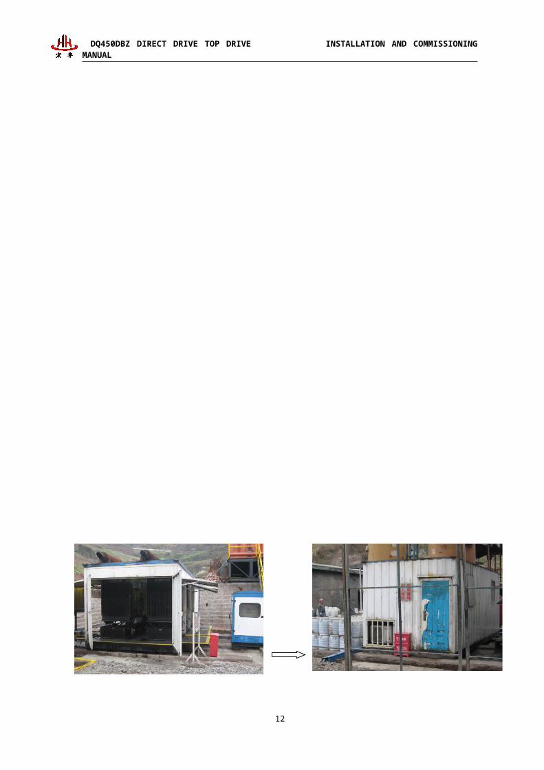
1) Lay out VFD house as per cable length. And select reasonable and shapely cable
arrangement according to layout of drill floor at well site.
5

DQ450DBZ DIRECT DRIVE TOP DRIVE INSTALLATION AND COMMISSIONING MANUAL
3) Place top drive house as per well site layout.
6
Fig. 3.4-1 lay out reasonable cable
line orientation as per well site.

DQ450DBZ DIRECT DRIVE TOP DRIVE INSTALLATION AND COMMISSIONING MANUAL
7
Fig. 3.4-2 hoisting top drive house to reasonable position steadily

DQ450DBZ DIRECT DRIVE TOP DRIVE INSTALLATION AND COMMISSIONING MANUAL
4) The top drive house should be placed on a smooth foundation.
5) Hang service loop of top drive as per the height of cable hanging board.
The cable of top drive mainly consists of main cable (main motor cable) and control
cable (auxiliary cable).
During installing the top drive, the cables need to be connected as follows:
① Top drive main motor cable: a service loop (26m), a mast cable (41m) and 4
ground cables (30m), 3 sections in all.
8
Fig. 3.4-3 top drive house is placed on smooth ground

DQ450DBZ DIRECT DRIVE TOP DRIVE INSTALLATION AND COMMISSIONING MANUAL
② Top drive auxiliary power cable: a service loop (61m), a ground cable (30m), 2
sections in all.
③ Top drive control cable: a service loop (61m), a ground cable (30m), 2 sections in
all.
④ 600VAC incoming cable: three pieces of ground cable (15m), one section in all.
⑤ Driller control cable: a control cable (60m), a PROFIBUS-DP cable (60m), one
section in all.
9

DQ450DBZ DIRECT DRIVE TOP DRIVE INSTALLATION AND COMMISSIONING MANUAL
3.4.2 Installation of mast guide wheel bracket
The mast guide wheel bracket including two parts: one part is hanging board
assembly for fixing cable flange plates at servicing section of top drive main motor cable
and mast section, and fastening corresponding connectors; the other part is wiring lug
assembly for fixing servicing sections of auxiliary power supply cable and control cable.
The arrangement of mast guide wheel bracket indicates the place of cable guide
wheel bracket. This arrangement is more ideal, the reasons are listed as follows:
When the height of mast is 39.6~44.2m and the top drive is lowered to the
position 22.9~25.9m above the drill floor, the height of bracket shall not make the cable
has strain and damage the cable.
When the top drive dropped on the drill floor, the height of bracket shall not
make the cable lowered on the floor.
The cable from electric control room should get to mast guide wheel bracket
through ground linearly.
And on above the driller’s cabin.
Caution: The operation of suspension equipment is lesser at this position. Place
mast guide wheel bracket at this position, probability of cable damage is really tiny.
The place of mast guide wheel bracket is determined by following several factors:
The height of mast
Location and type of locating plate
The length of removable devices (drill string, compensator, sheave and rotating
swivel)
The length of cable, besides otherwise requested.
Location of power unit
Placement of mast guide wheel bracket
1. Lift the mast guide wheel bracket on to drill floor by crane or other hoisting
equipment.
2. Lift the guide wheel bracket to desired location of mast by auxiliary winch (air
winch) or cathead line.
3. Assemble the cable guide wheel bracket onto locating plate.
10

DQ450DBZ DIRECT DRIVE TOP DRIVE INSTALLATION AND COMMISSIONING MANUAL
Caution: The type of locating plate determines installation hardware. Analyze
and discuss this installation hardware during rig dimensions measuring and before
installation.
1. The top drive cable hanging plate should be installed on the crossbeam of
mast right side and away from drill floor about 23.5m.
2. Install cable hanging plate at the right side of crossbeam of mast, make it
close to back crossbeam as far as possible, and form a safety space away from rotary
hose to prevent cable and rotary hose from rubbing and getting caught in.
(traveling) cable...........................................rotary hose
11
Fig. 3.4-4 cable hanging plate is installed at the right side of mast

DQ450DBZ DIRECT DRIVE TOP DRIVE INSTALLATION AND COMMISSIONING MANUAL
3.4.3 Connections of top drive auxiliary power and control cable
There are no breakpoints and trough connections at mast section and traveling
section of auxiliary power and control cable.
Connect all cables in turn from mast end (racking board):
① Install mast guide wheel bracket on the mast.
② Hang the centre sections of cable traveling section and mast section onto mast
guide wheel bracket, cable connector line without flange plate should be down.
③ Place ground cable and connect with cable mast section (connect with connector
in electric control room before commissioning and after all installation had been
finished).
④ One end of cable connecting line without flange plate should connect with
ground cable, and other end connected with cable connector of main body.
At last, test top drive slowly for several times after installation of electric loop for
top drive had been finished, and adjust it properly if necessary.
12
DQ450DBZ DIRECT DRIVE TOP DRIVE INSTALLATION AND COMMISSIONING MANUAL
Ensure the length of traveling control cable, and install cable wiring lug.
13
Fig. 3.4-5 ensure the length of traveling control cable

DQ450DBZ DIRECT DRIVE TOP DRIVE INSTALLATION AND COMMISSIONING MANUAL
14

DQ450DBZ DIRECT DRIVE TOP DRIVE INSTALLATION AND COMMISSIONING MANUAL
15
图 3.4-6固定穿线耳在控制线缆上
Fig. 3.4-7 lift wiring lug to drill floor

DQ450DBZ DIRECT DRIVE TOP DRIVE INSTALLATION AND COMMISSIONING MANUAL
3.4.4 Connection of main motor cable for top drive
Connect all cables in turn from mast end (racking board):
① Install mast guide wheel bracket on the mast.
② Hang the traveling cable onto mast guide wheel bracket, cable connector line
with longer connector should be down.
③ Hang the mast cable onto mast guide wheel bracket, place on ground in order
after extending downwards, the end without flange should be down.
④ Place ground cable and connect with mast cable (connect with connector in
electric control room before commissioning and after all installation had been finished).
⑥ Connect one end of traveling cable with mast cable, the other end connected with
16
Fig. 3.4-8 lift it to preset position by air winch and then fix it

DQ450DBZ DIRECT DRIVE TOP DRIVE INSTALLATION AND COMMISSIONING MANUAL
cable connector of main body.
17
Fig. 3.4-9 lifting main cable

DQ450DBZ DIRECT DRIVE TOP DRIVE INSTALLATION AND COMMISSIONING MANUAL
18
Fig. 3.4-10 installation and fixation of main cable

DQ450DBZ DIRECT DRIVE TOP DRIVE INSTALLATION AND COMMISSIONING MANUAL
3
.
4
.
5
Connections of 600VAC incoming cable and driller control cable
(1) When connect 600AC incoming cable, electric control room is connected by
quick connector, however, VFD/MCC house adopts quick connector or copper bar to
connect as per actual condition.
(2) Connect driller control cable. The socket joint mode should be carried out during
connecting its control cable and PROFIBUS-DP cable with electric control room end and
driller’s control cabinet respectively by quick connector.
Note: During cable connection, pay attention to color code of cable (A-phrase
stands for black, B-phrase is white and C-phrase is red), socket joint mode can be
done when the color is same.
Caution: Connect connectors which connected with electric control room after
devices are installed completely, to avoid occurring electric shock accident during
installation.
19
Fig. 3.4-11 butt main cable on cable hanging plate

DQ450DBZ DIRECT DRIVE TOP DRIVE INSTALLATION AND COMMISSIONING MANUAL
20
Embed ground wire

DQ450DBZ DIRECT DRIVE TOP DRIVE INSTALLATION AND COMMISSIONING MANUAL
3.5 Installation of guide rail and top drive
Installation procedures of guide rail and top drive are as follows:
21
Welding lifting lug top plate on crown block (if necessary)
Connecting lifting lug
Install hanging plate assembly (after erecting mast)
Iinstall guide rail and top drive
Install fixed beam 1
Install fixed beam 2
图 3.4-5准备铺设线缆
Fig. 3.4-12 lay out reasonable cable line orientation

DQ450DBZ DIRECT DRIVE TOP DRIVE INSTALLATION AND COMMISSIONING MANUAL
3.5.1 Installation of guide rail lifting lug
If the crown block has no preset hanging padeye matched with top drive, install
guide rail lifting lug at the top of mast during installing guide rail and top drive for first
time.
Weld the lifting lug top plate of guide rail on the crown block bottom beam of mast
top firmly, or fix it on top plate by bolts. Whole weight of guide rail and top drive main
body are borne by bolts. And ensure the welding seam can bear all weight of guide rail
and main body of top drive.
Caution: Pay attention to direction during connecting lifting lug. The correct
direction is shown as follows. If the crown block has already installed the hanging
padeye and the direction is inconsistent, and then adjust it by increasing shackles.
Caution: Magnaflux inspection should be carried out for welding position of
guide rail lifting lug top plate to make sure it firmly and reliably, prevent accidents
during drilling.
22

DQ450DBZ DIRECT DRIVE TOP DRIVE INSTALLATION AND COMMISSIONING MANUAL
3.5.2 Installation of guide rail hanging plate assembly
After welding suspending padeye (in necessity), install bow shackle, hanging plate
and connecting plate to finish the installation of hanging plate assembly.
Adjust the position of connecting pinhole of connecting plate and hanging plate as
per mast height. As shown in Fig. 3.5-2.
23
Fig. 3.5-1 suspending padeye of top drive guide rail

DQ450DBZ DIRECT DRIVE TOP DRIVE INSTALLATION AND COMMISSIONING MANUAL
24
Fig. 3.5-2 pinhole position confirmation

DQ450DBZ DIRECT DRIVE TOP DRIVE INSTALLATION AND COMMISSIONING MANUAL
Note: Install four locating bolts and thread
split pins during connecting plate connected with
hanging plate. Install shear pin and safety pin
into two pins connected connecting plate with
hanging plate. As shown in Fig. 3.5-3.
After connecting hanging plate, install 2
shackles: grade 35 and grade 30 respectively. Install
hanging plate assembly on the relevant padeye of
crown block before mast lifting.
If it is installed after mast lifting, the
installation sequence is following: after installation
of connecting plate and hanging plate, hoist it at
rear of drill floor by crane, and lift hanging plate
assembly to the back of traveling block by
cooperation of air winch and traveling block. And
then thread a wire rope with a length of 4m and a
diameter of 20mm into hole at upper end of
traveling block, lift both ends of rope rings
at lifting padeye of connecting plate by 2 shackles (3.25T or 4.75T) and make the top of
hanging plate assembly is higher than traveling block about 1m (adjust it as per the height
of operator) to hang it at padeye of crown block through shackle of hanging plate
assembly. As shown in Fig. 3.5-4.
25
Fig. 3.5-3 locating bolt installation
Fig. 3.5-4 lifting hanging plate assembly
Lifting hanging plate

DQ450DBZ DIRECT DRIVE TOP DRIVE INSTALLATION AND COMMISSIONING MANUAL
Caution: The small shackle
should be above and big one under
hanging plate assembly. As shown
in Fig. 3.5-5.
3.5.3 Installation of guide rail and
top drive
26
Fig. 3.5-5 shackle installation sequence

DQ450DBZ DIRECT DRIVE TOP DRIVE INSTALLATION AND COMMISSIONING MANUAL
1) Move the guide rail and top drive at front of ramp away from it for 1.5~2m.
2) Install section V, guide rail:
a. Lift 2 hoising points of section V, guide rail onto drill floor by crane, as shown in
fig. 3.5-6.
b. Threading 2 connecting pins into top of section V, guide rail, and lift it to the
position of top connecting pin by air winch.
c. and then loose the lifting shackle nearby the upper end of section V, guide rail,
and lift up it by cooperation of air winch and crane.
d. hang the steel wire rope of 5m on lower bail ring of traveling block,
and both ends of wire rope are threaded into relevant lifting holes of guiding plate of
section V, guide rail through shackle of 15T, and make top of section V is higher than
traveling block top about 600mm.The upper end had the function of assisting and
stabilizing section V, guide rail through air winch. As shown in Fig. 3.5-7.
Caution: The model of lifting shackle should be specified one. The installation of
top drive main body and guide rail must be separate when the wire rope lifted the single.
The air winch can be loosened after 2 sections of guide rail had been installed.
27
Fig.3.5-6 lifting section V, guide rail

DQ450DBZ DIRECT DRIVE TOP DRIVE INSTALLATION AND COMMISSIONING MANUAL
28
Fig. 3.5-7 section V installation

DQ450DBZ DIRECT DRIVE TOP DRIVE INSTALLATION AND COMMISSIONING MANUAL
29
Fig. 3.5-9 treading pins between section and section V of guide railⅣ
Fig.3.5-8 lift section , guide rail to drill floorⅣ

DQ450DBZ DIRECT DRIVE TOP DRIVE INSTALLATION AND COMMISSIONING MANUAL
3) Install section , guide rail:Ⅳ
a. at first lift section , guide rail onto drill floor, is shown in fig. 3.5-8. Ⅳ
b. adjust section by traveling block, make the centre of connecting padeye alignedⅤ
with lower hole of waist-type hole of section , and then thread connecting pins. AsⅣ
shown in Fig. 3.5-9.
c. loosen the hoisting shackle nearby the upper end of section , lift up travelingⅣ
block, at the same time, lift guide rail up through traveling block by crane to make
connecting pins sliding into upper end of waist type hole of section automatically.Ⅳ
Under the action of dead weight, section wiggles, when it swings to a certain position,Ⅳ
locking core locked with locking block, and then automatic positioning of guide rail
achieved. As shown in fig. 3.5-10 and fig. 3.5-11.
30
Fig. 3.5-10 lift up traveling block after treading pins

DQ450DBZ DIRECT DRIVE TOP DRIVE INSTALLATION AND COMMISSIONING MANUAL
4) Install sectionⅢ、Ⅱ、Ⅰ, guide rail:
The methods for installing section , and are similar to ones of section .Ⅲ Ⅱ Ⅰ Ⅳ
31
Fig. 3.5-11section locked with section V for positioning with dead weight after swingingⅣ
Fig. 3.5-12 installation of section of guide railⅢ
图-5导轨Ⅳ段吊装至钻台面

DQ450DBZ DIRECT DRIVE TOP DRIVE INSTALLATION AND COMMISSIONING MANUAL
5) Accomplish guide rail installation:
Lift traveling block after connection of 5 sections of guide rail finished, connect
guide rail section with hanging plate assembly through 2 connecting pins, as shown inⅤ
fig. 3.5-13 and Fig. 3.5-14.
Caution: Fix top drive pulley on section of guide rail before guide railⅠ
installation.
32
图-5导轨Ⅳ段吊装至钻台面

DQ450DBZ DIRECT DRIVE TOP DRIVE INSTALLATION AND COMMISSIONING MANUAL
Caution: Install shear pin into connecting pins connected between guide rail
and hanging plate.
6) Installation of top drive main body:
33
Fig. 3.5-13 connection between section V, guide rail and hanging plate
Fig. 3.5-14 guide rail installation completion
Threading pins, shear pins and safety pins

DQ450DBZ DIRECT DRIVE TOP DRIVE INSTALLATION AND COMMISSIONING MANUAL
Install main body of to drive after guide rail installed.
a. Lift main body of top drive onto drill floor by crane, as shown in Fig. 3.5-15.
34
Fig. 3.5-15 lift main body of top drive onto drill floor

DQ450DBZ DIRECT DRIVE TOP DRIVE INSTALLATION AND COMMISSIONING MANUAL
b. Lift top drive bail ring by hook via steel wire rope, at same time lift top drive to
vertical position, as shown in fig. 3.5-16.
c. adjust traveling block height properly, make top drive main body and pulley are at
35
Fig. 3.5-16 hook up bail ring by hook directly

DQ450DBZ DIRECT DRIVE TOP DRIVE INSTALLATION AND COMMISSIONING MANUAL
same height, and then install connecting bolts between them, i.e. lock main body onto
guide rail, is shown in fig. 3.5-17.
Caution: The connecting bolts between main body and pulley of top drive
36
Fig. 3.5-17 accomplish the bolts connection between top drive main body and pulley

DQ450DBZ DIRECT DRIVE TOP DRIVE INSTALLATION AND COMMISSIONING MANUAL
should be reliable and fastening.
Install oil cylinder connecting elevator link of balanced device on auxiliary hook of
hook. Install connecting cable and rotary hose of balanced device and main body of top
drive, as shown in fig. 3.5-18 and fig. 3.5-19.
Install balanced system before hydraulic system charging. The balanced system
includes two same hydraulic cylinders and its accessories (inc. hydraulic power
accumulator and related pipelines), one end of cylinder connected with bail ring, the
other end connected with hook ear ring, or connected on traveling block directly. The
power accumulator supplies energy by hydraulic oil and keep a preset pressure. Its value
preset by balance circuit of main manifold of hydraulic control system.
Structural drawing of balanced system
Installation of balanced system:
37

DQ450DBZ DIRECT DRIVE TOP DRIVE INSTALLATION AND COMMISSIONING MANUAL
1) Install ear rings.
Connect 2 elevator links of top drive with ear rings at both sides of hook.
2) Extend the piston of balance hydraulic cylinder:
Start top drive, turn mode valve of balance system from “RUN” to “RIG-UP”. The
piston rod of hydraulic cylinder extends completely now.
3) Install connecting clasps and pins.
Place the elevator link into connecting clasp groove of piston rod, thread pins, and
then turn the mode of balanced mechanism to “RUN”.
38
Fig. 3.5-18 balanced device installation

DQ450DBZ DIRECT DRIVE TOP DRIVE INSTALLATION AND COMMISSIONING MANUAL
d. Align the top drive with well bore centre, and install reverse torque beam, as
39
Fig. 3.5-19 installation of connection cable and rotary hose

DQ450DBZ DIRECT DRIVE TOP DRIVE INSTALLATION AND COMMISSIONING MANUAL
shown in fig. 3.5-20.
e. Install upper fixed beam.
40
Fig. 3.5-20 adjust wellbore centre and install reverse torque beam

DQ450DBZ DIRECT DRIVE TOP DRIVE INSTALLATION AND COMMISSIONING MANUAL
41
Fig. 3.5-21 installation of upper fixing beam

DQ450DBZ DIRECT DRIVE TOP DRIVE INSTALLATION AND COMMISSIONING MANUAL
f. Add the hydraulic oil for top drive by manual pump after installation.
g. Remove 4 locating pins of top drive pulley and guide rail at last, so the
installation of top drive had been finished.
Caution: Install top drive cable and rotary hose before adjusting the wellbore
centre.
42
Fig. 3.5-22 hydraulic oil adding

DQ450DBZ DIRECT DRIVE TOP DRIVE INSTALLATION AND COMMISSIONING MANUAL
3.6 Commissioning of balanced system
Caution: Commissioning should be carried out after all parts and components
had been installed.
During working of balance mechanism, oil supply pressure of balanced cylinder is
1600 psi and its load bearing is about 15860kg.The procedures for adjusting load bearing
are following:
1) Turn the mode switch to RUN, spin pressure reducing valve to lowest
counterclockwise.
2) Test the pressure at the location 15.2 (see schematic drawing), the pressure should
be zero.
3) Test the pressure at oil inlet of balance cylinder, observe the top drive position on
hook.
Adjust pressure reducing relief control valve clockwisely, observe pressure gauge at
oil inlet 15.2 (see schematic drawing) until the top drive separated from hook, at this
time, adjust pressure back of 25 psi to make top drive bail ring seat go back to hook.
Test for bouncing
If the function of “bouncing” runs normally, the load balanced mechanism bore is
15860kg and the pressure at the location 15.2 is about 1800 psi. Increased 200psi
pressure is provided by No. 18 relief valve (schematic drawing).The procedures for
adjusting pressure are as follows:
1) Turn the knob “mode” to “RUN” active mode, open bouncing switch, measure
the pressure at the locations of 15.2 and 15.2, adjust relief valve (No. 18) to the lowest
position counterclockwisely.
2) Adjust No. 18 relief valve clockwisely to make the pressure at location 15.2
increased slowly until the bail ring separated from hook (at this time the elevator will
take a stand by top drive).
Caution: Adjust relief valve 18 slowly and make the pressure at the location
15.2 steady.
3.7 Installation of tilting oil cylinder
Link tilt device mainly consists of tilting oil cylinder, elevator link clamp seat, oil
43

DQ450DBZ DIRECT DRIVE TOP DRIVE INSTALLATION AND COMMISSIONING MANUAL
cylinder supporting plate, oscillating bearing and nipple etc, action of whole mechanism
can be realized by controlling of hydraulic mechanism.
Installation and commissioning of link tilt device:
1) Connect link tilt oil cylinder tail with rotating head.
2) Make tilting oil cylinder extended slowly until to max. position.
3) Fix U-type screw clamp seat onto elevator link, move the top drive elevator link
to the position of 35°manually, adjust U-type screw to make the pin hole of U-type clamp
seat aligned with one of link tilt oil cylinder, and then connect and fix them.
4) Retraction should be carried out by operating tilting oil cylinder, observe whether
there are blockages and loosing at all active locations. Retract tilting oil cylinder
completely and measure if caster angle of top drive elevator link is ideal.
44

DQ450DBZ DIRECT DRIVE TOP DRIVE INSTALLATION AND COMMISSIONING MANUAL
4. Check
After top drive installation, check it thoroughly for commissioning to make sure all
installations had finished as per requirements in manual and all transport fixers had been
removed.
The inspection should be done by technical principal installing top drive.
The inspection should be carried out according to Installation and check list of top
drive device which given in attached list. The check list just has the directive function, so
if there are some contents missing, the inspector should judge and deal with them by
themselves.
Warning: The cable connector must be socketed and connected at marking
position, and then lock it by locking screw to avoid false connection, and cable and
connector damage.
Caution: The cable connector must be connected firmly, there are seal rings in
female joint, so check the seal ring during installation, and then lock them to avoid
false connection, water inflow, or cable and connector damage.
5. Running commissioning
Running commissioning should be carried out after installation inspection without
incorrect installation and omission. It should be processed according to following
procedures strictly.
5.1 Commissioning of guide rail pulley
Lift and lower down the top drive device slowly within guide rail overall length to
observe whether the top drive slides normally, and if the top drive cable and hydraulic
pipeline are normal.
5.2 Power transmission of electric control system
Ensure the sequence of line incoming is correct before starting up, power on the
electric control system, check whether the PLC/MCC system, instrument and indicators
of power system and monitoring system work normally.
5.3 Commissioning of main motor fan
Commissioning of main motor fan should be carried out as per following procedures
45

DQ450DBZ DIRECT DRIVE TOP DRIVE INSTALLATION AND COMMISSIONING MANUAL
and make sure the fan works normally.
1) Ensure the operation knobs of main motor are in stop position.
2) Start up fan manually to make sure the rotating direction.
3) Check fan delivery.
5.4 Commissioning of main motor
Start main motor, operate it at low speed, observe rotating direction and make sure
the motor rotating direction accord with the direction indicated on the operation panel.
5.5 Commissioning of hydraulic system
Fill oil into oil tank to proper level, make pump housing be full of oil by opening oil
drain valve of hydraulic pump, start hydraulic pump motor, observe whether pump
rotating direction, pressure and turning are normally, and then test all actions as per
functions of hydraulic system one by one to see whether the actions can be achieved.
46