
Case Studies UNDP: SRI LANKA WILDLIFE CONSERVATION SOCIETY, Sri Lanka
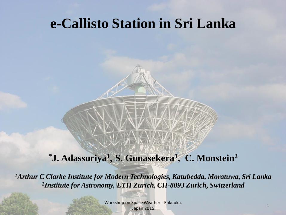
e-Callisto Station in Sri Lanka
*J. Adassuriya1, S. Gunasekera1, C. Monstein2
1Arthur C Clarke Institute for Modern Technologies, Katubedda, Moratuwa, Sri Lanka2Institute for Astronomy, ETH Zurich, CH-8093 Zurich, Switzerland
1Workshop on Space Weather - Fukuoka,
Japan 2015
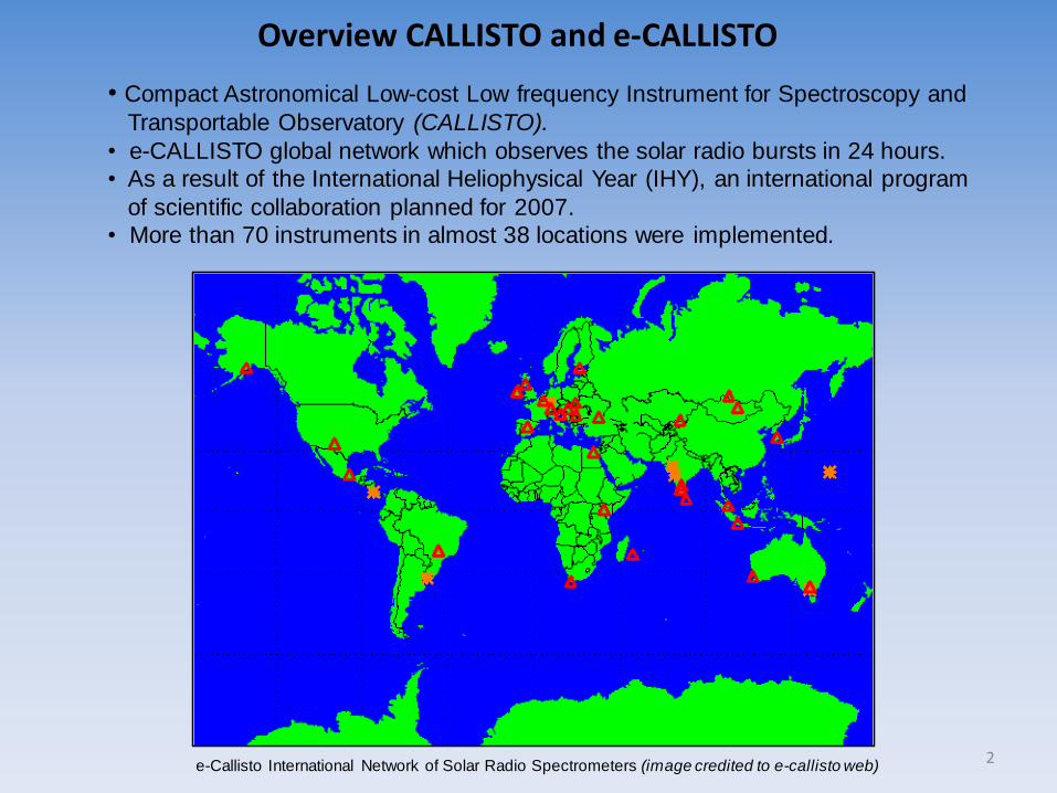
• Compact Astronomical Low-cost Low frequency Instrument for Spectroscopy and
Transportable Observatory (CALLISTO).
• e-CALLISTO global network which observes the solar radio bursts in 24 hours.
• As a result of the International Heliophysical Year (IHY), an international program
of scientific collaboration planned for 2007.
• More than 70 instruments in almost 38 locations were implemented.
Overview CALLISTO and e-CALLISTO
e-Callisto International Network of Solar Radio Spectrometers (image credited to e-callisto web) 2
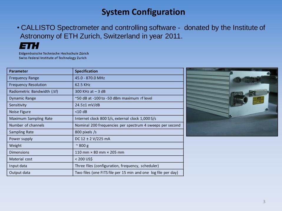
System Configuration
•CALLISTO Spectrometer and controlling software - donated by the Institute of
Astronomy of ETH Zurich, Switzerland in year 2011.
Parameter Specification
Frequency Range 45.0 - 870.0 MHz
Frequency Resolution 62.5 KHz
Radiometric Bandwidth (f) 300 KHz at – 3 dB
Dynamic Range ~50 dB at -100 to -50 dBm maximum rf level
Sensitivity 24.5±1 mV/dB
Noise Figure <10 dB
Maximum Sampling Rate Internet clock 800 S/s, external clock 1,000 S/s
Number of channels Nominal 200 frequencies per spectrum 4 sweeps per second
Sampling Rate 800 pixels /s
Power supply DC 12 ± 2 V/225 mA
Weight ~ 800 g
Dimensions 110 mm × 80 mm × 205 mm
Material cost < 200 US$
Input data Three files (configuration, frequency, scheduler)
Output data Two files (one FITS file per 15 min and one log file per day)
3

• Spectral Overview while the antenna is attached to the preamplifier.
• Spectral Overview with a 50 Ω termination resistor instead of the antenna attached to
the input of the preamplifier as reference.
• Very Long Baseline Interferometry (VLBI) threshold - this is the definition of the ITU ofmaximum rfi-level to get maximum 10% data loss in radio astronomical observations.• 50 ohm represents an equivalent antenna temperature of 300 Kelvin.
Spectral Overview Compared with Natural Sources
4
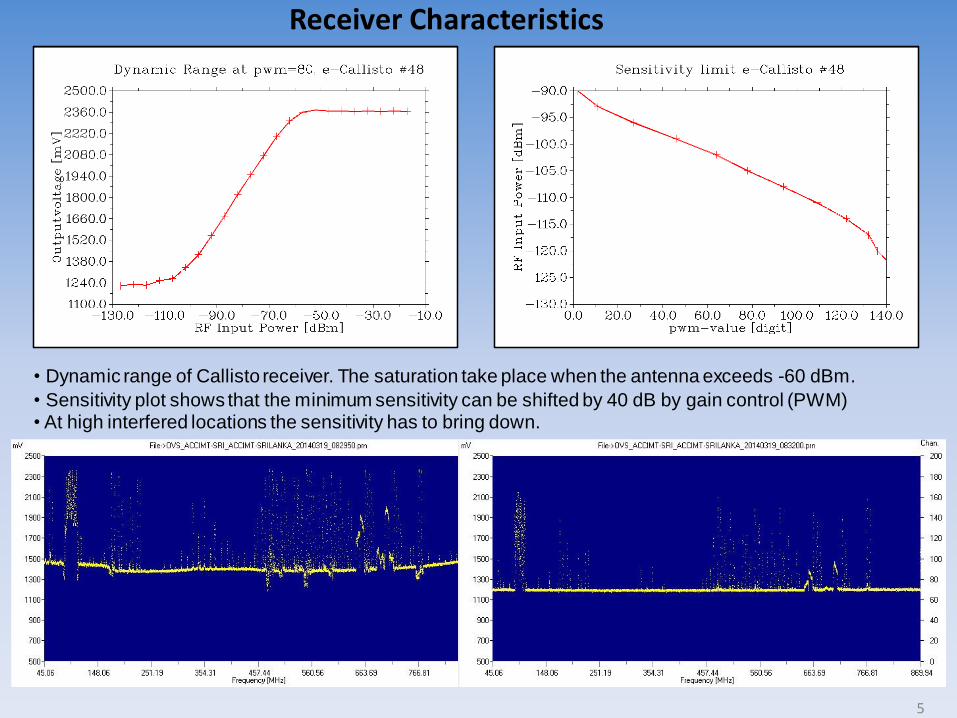
• Dynamic range of Callisto receiver. The saturation take place when the antenna exceeds -60 dBm.
• Sensitivity plot shows that the minimum sensitivity can be shifted by 40 dB by gain control (PWM)• At high interfered locations the sensitivity has to bring down.
Receiver Characteristics
5
Logarithmic – Periodic Antenna and Pre- Amplifier - ACCIMT
Parameter Specifications
Range 45 – 870 MHz
Theoretical Gain 7 dBi
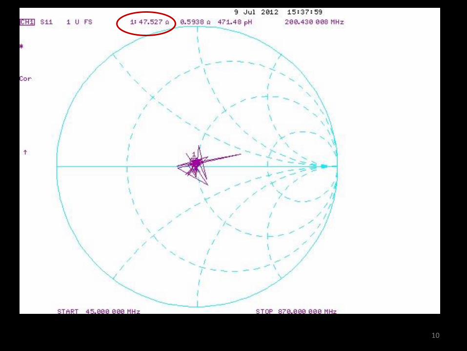
Average Impedance 49.3 Ω
VSWR <1.5
Overall Height 5.38 m
Width of the longest dipole 3.33 m
Plane of Polarization Linear polarized pointing to zenith
Bandwidth 60 degrees from zenith
Effective Area 1.7 m2 at 145 MHz
Approximate Cost 250 USD
6

Design Steps of Log-Periodic Antenna
Images Credited : F. Hutira & Jan Bezek
Periodicity
Relative Spacing
Number of Dipoles
Dipole Length
Relative Spacing
7
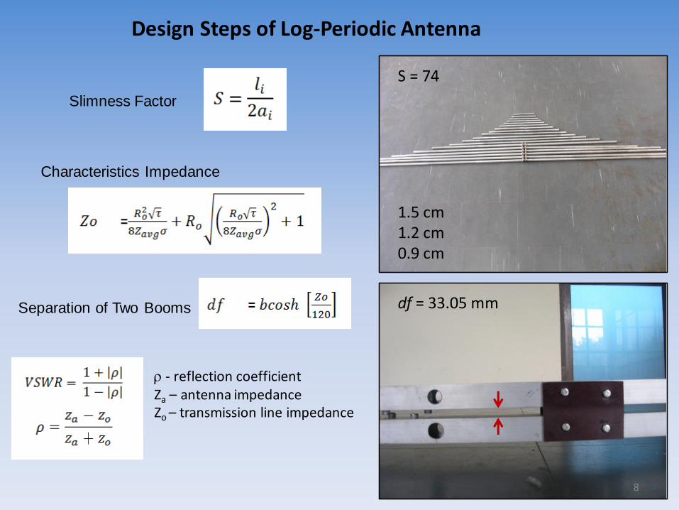
1.5 cm1.2 cm0.9 cm
Design Steps of Log-Periodic Antenna
Slimness Factor
Separation of Two Booms
S = 74
df = 33.05 mm
Characteristics Impedance
8
- reflection coefficientZa – antenna impedanceZo – transmission line impedance
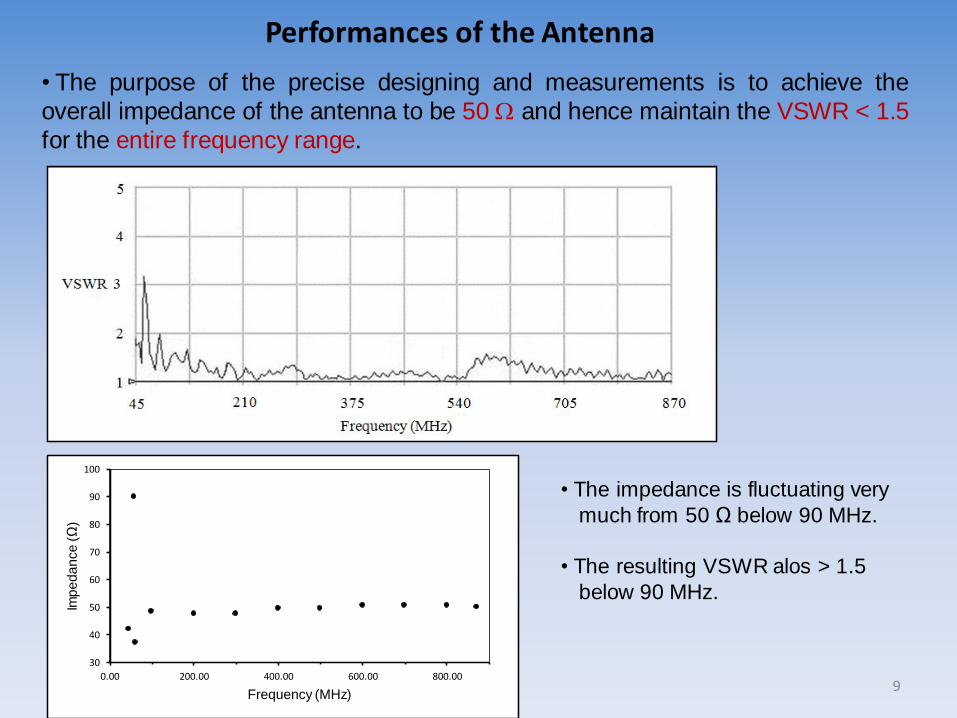
Performances of the Antenna
• The purpose of the precise designing and measurements is to achieve the
overall impedance of the antenna to be 50 and hence maintain the VSWR < 1.5
for the entire frequency range.
30
40
50
60
70
80
90
100
0.00 200.00 400.00 600.00 800.00
Imp
ed
an
ce
(Ω
)
Frequency (MHz)
• The impedance is fluctuating very
much from 50 Ω below 90 MHz.
• The resulting VSWR alos > 1.5
below 90 MHz.
9
10
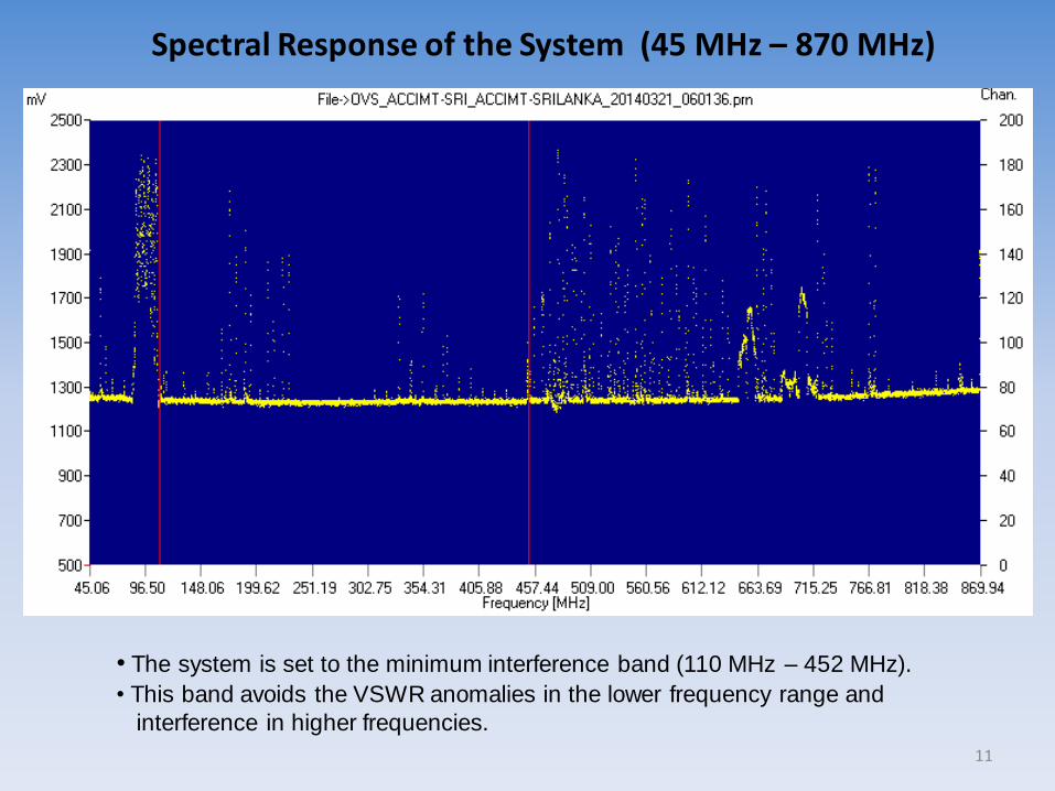
Spectral Response of the System (45 MHz – 870 MHz)
• The system is set to the minimum interference band (110 MHz – 452 MHz).
• This band avoids the VSWR anomalies in the lower frequency range and
interference in higher frequencies.
11

The potential solar radio bursts detecting by the system…
Effective area of the antenna ( = 145 MHz) = 1.7 m2
System noise = 2910 K
Power flux density = 4 x 10-20 W/Hz or -194 dBW/Hz
• Assume that a solar radio bursts can be reliably detected if it is at least 10dB above
the system noise floor
• The required solar burst power flux density is = - 194 dBW + 10 dB = -184 dBW
Power flux density for the burst = 3.98 X 10⁻¹⁹ dBW/Hz
Spectral flux density = 4.68 x 10⁻¹⁹ W/m2/Hz
By definition one solar flax unit (sfu) = 10-22 W/m2/Hz
Spectral flux density = 4680 sfu at 145 MHz
12
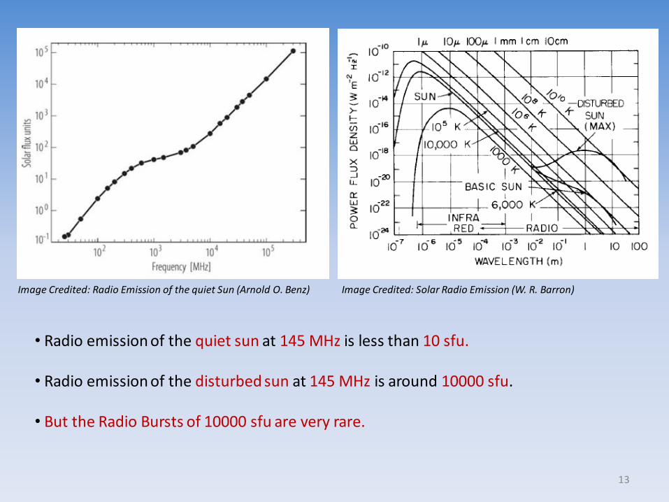
Image Credited: Radio Emission of the quiet Sun (Arnold O. Benz) Image Credited: Solar Radio Emission (W. R. Barron)
• Radio emission of the quiet sun at 145 MHz is less than 10 sfu.
• Radio emission of the disturbed sun at 145 MHz is around 10000 sfu.
• But the Radio Bursts of 10000 sfu are very rare.
13
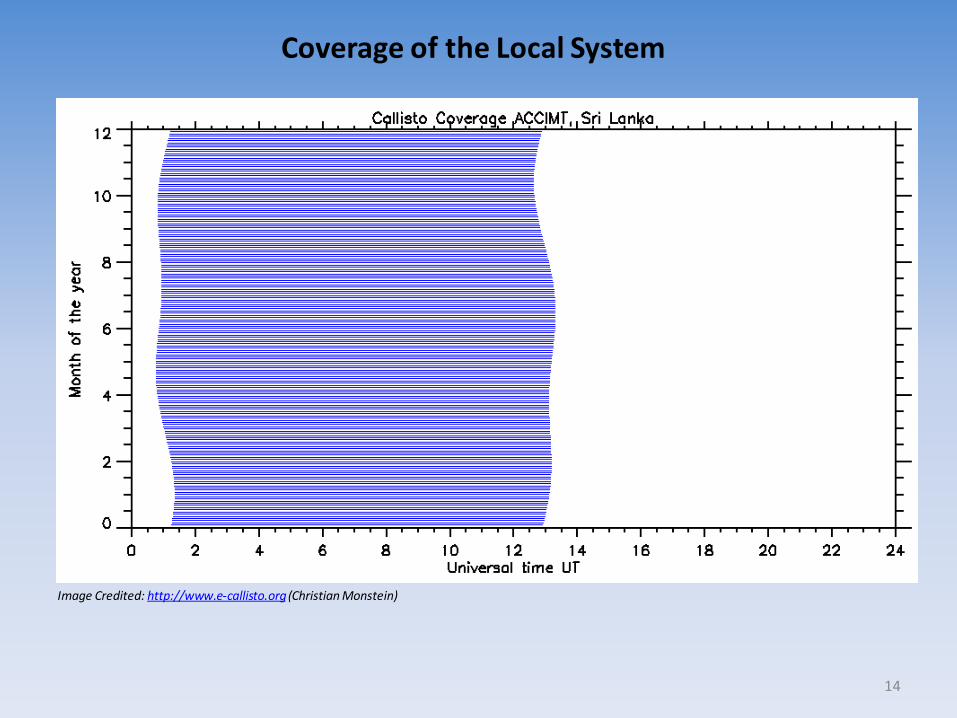
Image Credited: http://www.e-callisto.org(Christian Monstein)
Coverage of the Local System
14
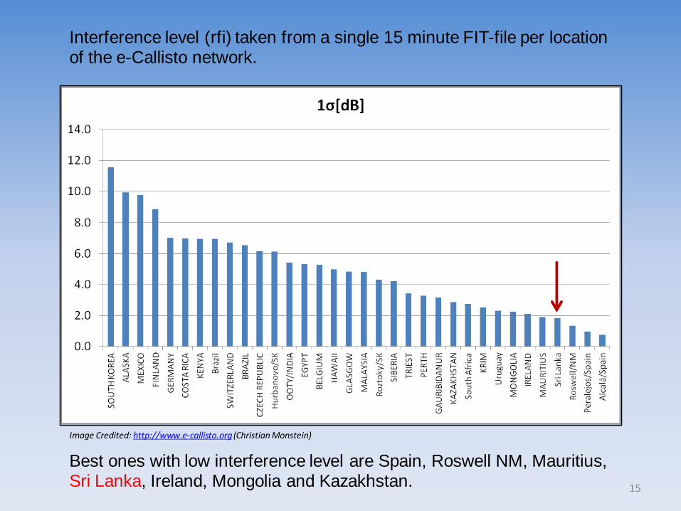
Interference level (rfi) taken from a single 15 minute FIT-file per location of the e-Callisto network.
Best ones with low interference level are Spain, Roswell NM, Mauritius, Sri Lanka, Ireland, Mongolia and Kazakhstan.
Image Credited: http://www.e-callisto.org(Christian Monstein)
15
First Result
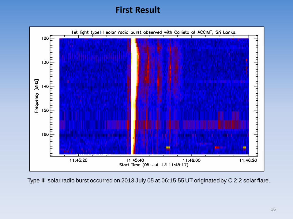
Type III solar radio burst occurred on 2013 July 05 at 06:15:55 UT originated by C 2.2 solar flare.
16
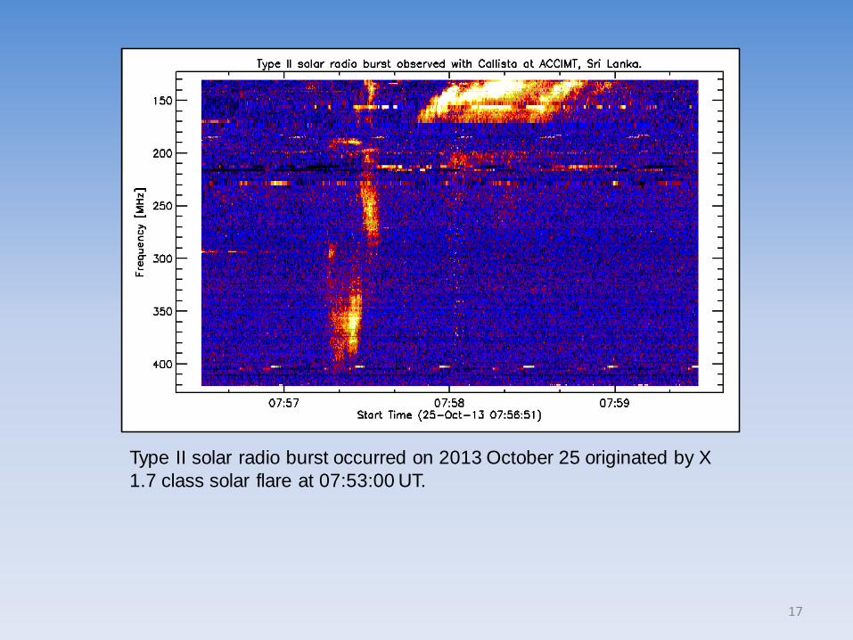
Type II solar radio burst occurred on 2013 October 25 originated by X
1.7 class solar flare at 07:53:00 UT.
17
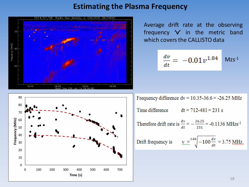
18
0
10
20
30
40
50
60
70
80
90
0 100 200 300 400 500 600 700
Fre
qu
en
cy (
MH
z)
Time (s)
Estimating the Plasma Frequency
Average drift rate at the observingfrequency ‘ν’ in the metric bandwhich covers the CALLISTO data
Mzs-1
19
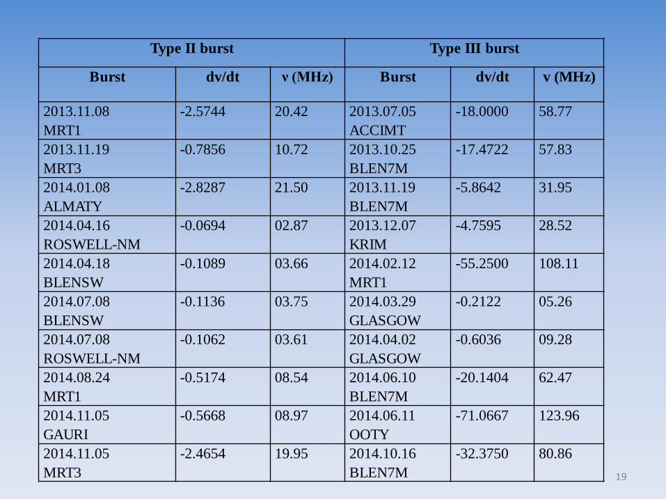
Type II burst Type III burst
Burst dv/dt ν (MHz) Burst dv/dt v (MHz)
2013.11.08
MRT1
-2.5744 20.42 2013.07.05
ACCIMT
-18.0000 58.77
2013.11.19
MRT3
-0.7856 10.72 2013.10.25
BLEN7M
-17.4722 57.83
2014.01.08
ALMATY
-2.8287 21.50 2013.11.19
BLEN7M
-5.8642 31.95
2014.04.16
ROSWELL-NM
-0.0694 02.87 2013.12.07
KRIM
-4.7595 28.52
2014.04.18
BLENSW
-0.1089 03.66 2014.02.12
MRT1
-55.2500 108.11
2014.07.08
BLENSW
-0.1136 03.75 2014.03.29
GLASGOW
-0.2122 05.26
2014.07.08
ROSWELL-NM
-0.1062 03.61 2014.04.02
GLASGOW
-0.6036 09.28
2014.08.24
MRT1
-0.5174 08.54 2014.06.10
BLEN7M
-20.1404 62.47
2014.11.05
GAURI
-0.5668 08.97 2014.06.11
OOTY
-71.0667 123.96
2014.11.05
MRT3
-2.4654 19.95 2014.10.16
BLEN7M
-32.3750 80.86
Conclusions
• In collaboration with ETH Zurich, the Arthur C Clarke Institute successfully
constructed a CALLISTO station in Sri Lanka.
• This is the first observation facility to investigate celestial object in radio region
in Sri Lanka.
• The system is connected to the e-CALLISTO network which included another solar
observation station in radio region.
• The system is capable of detecting solar radio burst in moderate solar flares as well.
(Type C class solar flares)
• The system can be used for research purpose as well as developments by:
- contributing for data analysis
- enhancing the system, introducing solar tracker, designing pre-amplifier etc.
20