DYNAPAC CA500 MAINTENANCE - Stephenson Equipment
35
DYNAPAC CA500 Box 504, SE-371 23 Karlskrona, Sweden Phone: +46 455 30 60 00, Fax: +46 455 30 60 30 www.dynapac.com M500EN1 MAINTENANCE
Transcript of DYNAPAC CA500 MAINTENANCE - Stephenson Equipment
DYNAPAC CA500
Box 504, SE-371 23 Karlskrona, Sweden
Phone: +46 455 30 60 00, Fax: +46 455 30 60 30
www.dynapac.com
M500EN1
MAINTENANCE

19ILF015WO1
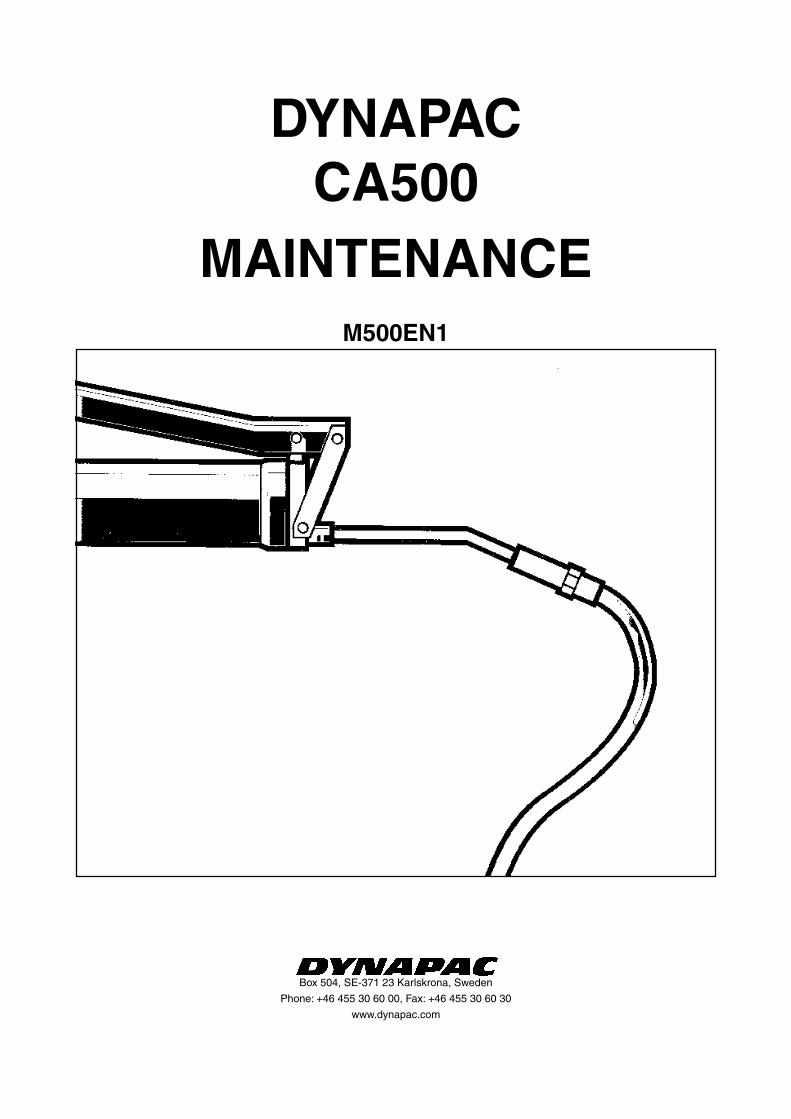
Vibratory RollerCA500
MaintenanceM500EN1, October 2004
Diesel engine: CA500: Cummins B5.9-VE-TAA
These instructions apply from: CA500 PIN (S/N) *79290607*
Reservation for changes.Printed in Sweden.
The Dynapac CA500 is available in D (smooth drum) and PD (padfoot) versions, of which the CA500D is designed for compacting rock fill. The main range of application for the PD versions is
on cohesive material and weathered stone material.
All types of base courses and subbase courses can be compacted deeper and the interchangeable drums, D to PD, and vice versa, facilitate even greater variety in the range of application.
Certain accessories, such as the compaction meter, tachograph and the DCA field computer, are described in separate instructions.
KEEP THIS M
ANUAL FOR
FUTURE REFERENCE

2 CA500 M500EN1
CONTENTS
Read the entire manual before starting any service work.
Ensure that ventilation (extraction) is adequa-te if the engine is run indoors.
It is essential that the machine is cared for in a proper manner to ensure satisfactory operation. Keep the mach-ine clean to facilitate quick and timely detection of any leakage, loose bolts and loose connections.
Make a habit each day, before starting up, of checking the roller to detect any leakage or damage. Also check the ground underneath the roller, where it is most often easier to detect any leakage.
TAKE CARE OF THE ENVIRONMENTDo not leave behind any oil, fuel or other sub-stances that are detrimental to the environment.
This manual contains instructions for periodic measures that should normally be performed by the operator.
The manufacturer’s instructions noted in the engine manual also apply. This is placed under a separate flap in the roller’s product folder.
GENERAL
Safety instructions—Personal safety
Special caution—Machine or component damage
WARNING SYMBOLS
CALIFORNIA
Proposition 65 Warning
Diesel engine exhaust and some of its constituents are known to the State of California to cause cancer, birth defects, and other reproductive harm.
PageLubricants and symbols .................................................... 3Technical specifications ................................................. 4-6Maintenance schedule ...................................................... 7Maintenance measures ................................................ 8, 9Every 10 hours of operation (Daily) ........................... 10-13Every 50 hours of operation (Weekly) ....................... 14-16Every 250 hours of operation (Monthly) .................... 17-21Every 500 hours of operation (Every three months) ....... 22Every 1000 hours of operation (Every six months) .... 23-26Every 2000 hours of operation (Yearly) .................... 27, 28Long-term Storage ......................................................... 29Special instructions ........................................................ 30Electrical system, fuses ............................................ 31, 32
3CA500 M500EN1
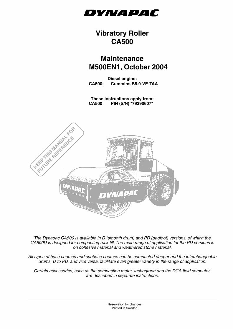
LUBRICANTS AND SYMBOLS
ENGINE OIL Shell Rimula Super 15W/40 or equivalent API Service CH-4 (CG-4)
HYDRAULIC FLUID ambient temperature -10° C - +40° C (14°F - 104°F) Shell Tellus TX68 or equivalentambient temperature higher than +40° C Shell Tellus T100 or equivalent
TRANSMISSION OIL lambient temperature Shell Spirax SAE 80W/90, HD API, GL-5 -15°C - +40°C (5°F - 104°F)ambient temperature Shell Spirax HD85W/140 or equivalenthigher than +40°C (above 104°F)
DRUM-CARTRIDGE OIL Synthetic oil, MOBIL SHC 629.
GREASE Shell LGHB2 (NLGI-class 2) or equivalent for the articulation.
Shell Retinax LX2 or equivalent for other grease points.
FUEL See engine manual
COOLANT Shell Anti Freeze 402 or equivalent.50/50 mixture with water Anti-freeze down to about -35°C (-31°F).
Engine, oil level Air filter
Engine, oil filter Battery
Hydraulic reservoir, level Tire pressure
Hydraulic fluid filter Drum, oil level
Transmission, oil level Coolant, level
Lubricating oil Recycling
Fuel filter
Always use high-quality lubricants in the recommended amounts. Too much grease or oil can cause overheating and subsequent increased wear.
Other lubricants are required for driving in extremely high or low ambient temperatures. See the “Special instructions” chapter, or consult Dynapac.
4 CA500 M500EN1
TECHNICAL SPECIFICATIONS
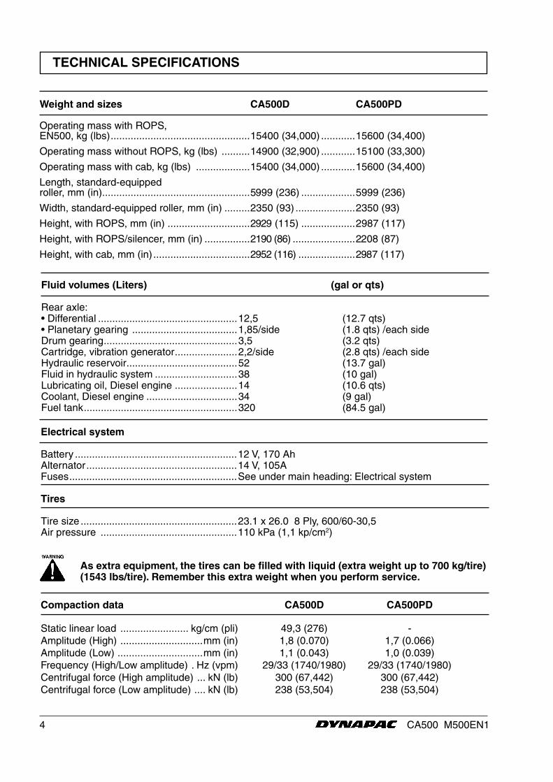
Weight and sizes CA500D CA500PD
Operating mass with ROPS, EN500, kg (lbs) .................................................15400 (34,000) ............15600 (34,400)
Operating mass without ROPS, kg (lbs) ..........14900 (32,900) ............15100 (33,300)
Operating mass with cab, kg (lbs) ...................15400 (34,000) ............15600 (34,400)
Length, standard-equipped roller, mm (in) ....................................................5999 (236) ...................5999 (236)
Width, standard-equipped roller, mm (in) .........2350 (93) .....................2350 (93)
Height, with ROPS, mm (in) .............................2929 (115) ...................2987 (117)
Height, with ROPS/silencer, mm (in) ................2190 (86) ......................2208 (87)
Height, with cab, mm (in) ..................................2952 (116) ....................2987 (117)
Fluid volumes (Liters) (gal or qts)
Rear axle: • Differential .................................................12,5 (12.7 qts) • Planetary gearing .....................................1,85/side (1.8 qts) /each sideDrum gearing ...............................................3,5 (3.2 qts)Cartridge, vibration generator ......................2,2/side (2.8 qts) /each sideHydraulic reservoir .......................................52 (13.7 gal) Fluid in hydraulic system .............................38 (10 gal)Lubricating oil, Diesel engine ......................14 (10.6 qts)Coolant, Diesel engine ................................34 (9 gal)Fuel tank ......................................................320 (84.5 gal)
Electrical system
Battery .........................................................12 V, 170 AhAlternator .....................................................14 V, 105AFuses ...........................................................See under main heading: Electrical system
Tires
Tire size .......................................................23.1 x 26.0 8 Ply, 600/60-30,5Air pressure ................................................110 kPa (1,1 kp/cm2)
As extra equipment, the tires can be filled with liquid (extra weight up to 700 kg/tire) (1543 lbs/tire). Remember this extra weight when you perform service.
Compaction data CA500D CA500PD Static linear load ........................ kg/cm (pli) 49,3 (276) -Amplitude (High) .............................mm (in) 1,8 (0.070) 1,7 (0.066)Amplitude (Low) ..............................mm (in) 1,1 (0.043) 1,0 (0.039)Frequency (High/Low amplitude) . Hz (vpm) 29/33 (1740/1980) 29/33 (1740/1980)Centrifugal force (High amplitude) ... kN (lb) 300 (67,442) 300 (67,442)Centrifugal force (Low amplitude) .... kN (lb) 238 (53,504) 238 (53,504)
5CA500 M500EN1
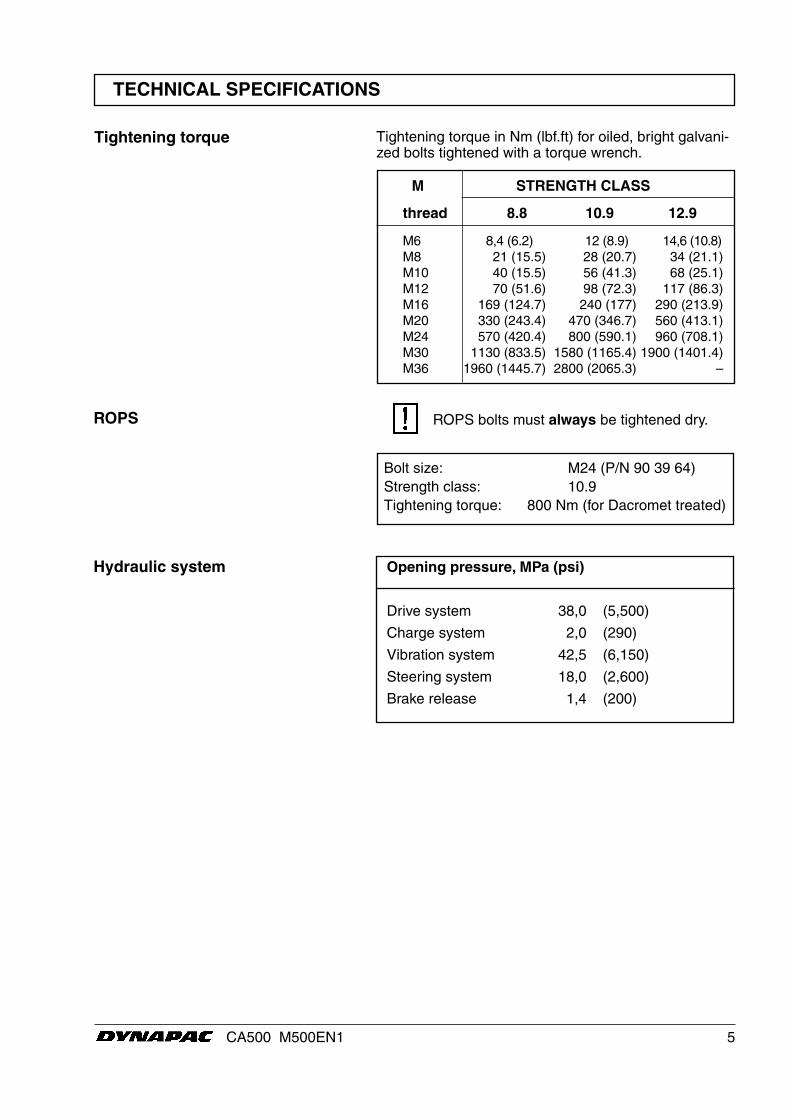
Opening pressure, MPa (psi)
Drive system 38,0 (5,500)
Charge system 2,0 (290)
Vibration system 42,5 (6,150)
Steering system 18,0 (2,600)
Brake release 1,4 (200)
Tightening torque
Hydraulic system
ROPS
M STRENGTH CLASS
thread 8.8 10.9 12.9
M6 8,4 (6.2) 12 (8.9) 14,6 (10.8) M8 21 (15.5) 28 (20.7) 34 (21.1) M10 40 (15.5) 56 (41.3) 68 (25.1) M12 70 (51.6) 98 (72.3) 117 (86.3) M16 169 (124.7) 240 (177) 290 (213.9) M20 330 (243.4) 470 (346.7) 560 (413.1) M24 570 (420.4) 800 (590.1) 960 (708.1) M30 1130 (833.5) 1580 (1165.4) 1900 (1401.4) M36 1960 (1445.7) 2800 (2065.3) –
Tightening torque in Nm (lbf.ft) for oiled, bright galvani-zed bolts tightened with a torque wrench.
Bolt size: M24 (P/N 90 39 64)Strength class: 10.9Tightening torque: 800 Nm (for Dacromet treated)
ROPS bolts must always be tightened dry.
TECHNICAL SPECIFICATIONS
6 CA500 M500EN1
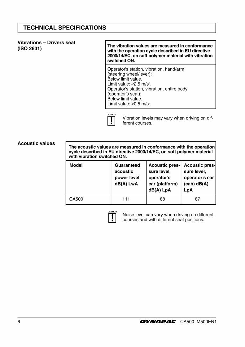
CA500 111 88 87
The acoustic values are measured in conformance with the operation cycle described in EU directive 2000/14/EC, on soft polymer material with vibration switched ON.
Acoustic values
Model Guaranteed acoustic power level dB(A) LwA
Acoustic pres-sure level, operator’s ear (platform) dB(A) LpA
Acoustic pres-sure level, operator’s ear (cab) dB(A) LpA
Noise level can vary when driving on different courses and with different seat positions.
The vibration values are measured in conformance with the operation cycle described in EU directive 2000/14/EC, on soft polymer material with vibration switched ON.
Operator’s station, vibration, hand/arm (steering wheel/lever): Below limit value. Limit value: <2.5 m/s2. Operator’s station, vibration, entire body (operator’s seat): Below limit value. Limit value: <0.5 m/s2.
Vibrations – Drivers seat(ISO 2631)
Vibration levels may vary when driving on dif-ferent courses.
TECHNICAL SPECIFICATIONS

7CA500 M500EN1
MAINTENANCE SCHEDULE
1 2 3 4 5 6 7 8 9 33 10 11 12
26 25 24 23 22 21 20 19 18 17 16 15 14
13
32
31
30
29
28
27
Fig. 1 Service points
1. Radiator grille 2. Oil level, diesel engine 3. Fuel filter, fuel pre-filter 4. Air filter 5. Hydraulic reservoir, sight glass 6. Breather filter 7. Hydraulic filter, x1 8. Drain hydraulic reservoir 9. Hydraulic fluid, filling10.. Fuse box11. Drum cartridge oil filler, x212. Drum gearbox
13. Scrapers14. Drum cartridge oil, level plug, x215. Rubber elements and fastening screws16. Steering joint17. Steering cylinder, x218. Flywheel casing, hydraulic pumps19. Wheel nuts20. Tire pressure21. Rear axle, differential22. Rear axle, planetary gearing, x223. Rear axle suspension, two sides24. Oil filter, diesel engine
25. Draining, fuel tank26. Engine suspension, x427. Feed pump, fuel28. Diesel fuel, filling29. Battery30. Radiator31. Hydraulic fluid cooler32. Drive belts, cooling, alternator33. Forward/Reverse lever
8 CA500 M500EN1
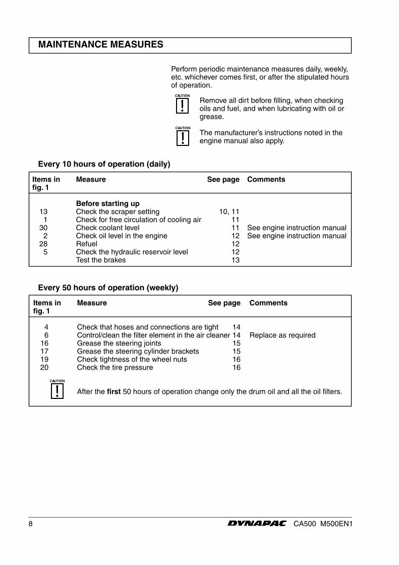
Perform periodic maintenance measures daily, weekly, etc. whichever comes first, or after the stipulated hours of operation.
Remove all dirt before filling, when checking oils and fuel, and when lubricating with oil or grease.
The manufacturer’s instructions noted in the engine manual also apply.
MAINTENANCE MEASURES
Every 10 hours of operation (daily)
Items in Measure See page Commentsfig. 1
4 Check that hoses and connections are tight 14 6 Control/clean the filter element in the air cleaner 14 Replace as required 16 Grease the steering joints 15 17 Grease the steering cylinder brackets 15 19 Check tightness of the wheel nuts 16 20 Check the tire pressure 16 After the first 50 hours of operation change only the drum oil and all the oil filters.
Every 50 hours of operation (weekly)
Items in Measure See page Commentsfig. 1
Before starting up 13 Check the scraper setting 10, 11 1 Check for free circulation of cooling air 11 30 Check coolant level 11 See engine instruction manual 2 Check oil level in the engine 12 See engine instruction manual 28 Refuel 12 5 Check the hydraulic reservoir level 12 Test the brakes 13

9CA500 M500EN1
MAINTENANCE MEASURES
Items in Measure See page Commentsfig. 1
22 Check the oil level in the rear axle/planetary gearing 17 24 Change engine oil and oil filter 17 See engine instruction manual 12 Check oil level in the gearbox 18 Accessory D/PD 14 Check oil level in the drum cartridge 18, 19 31 Clean the coolers 20 19, 23 Inspect tightening of bolted joints 20 Applies only to new or renovated component. 15 Check rubber elements and bolted joints 21 29 Check the battery 21
Every 250 hours of operation (monthly)
Items in Measure See page Commentsfig. 1
7 Change the hydraulic filter 23 8 Drain condensation from the hydraulic reservoir 24 25 Drain condensation from the fuel tank 24 4 Replace main filter in the air cleaner 24 21 Change oil in the rear axle differential 25 22 Change oil in the rear axle planetary gearing 26 Check engine valve clearance See engine instruction manual 32 Check belt tension of drive system See engine instruction manual
Every 1000 hours of operation (every six months)
Items in Measure See page Commentsfig. 1
8, 9 Change the hydraulic fluid 27 12 Change oil in the drum cartridge 27 12 Change oil in the drum gearbox 28 Accessory D/PD 33 Lubricate the Forward/Reverse controls 28
Every 2000 hours of operation (yearly)
Items in Measure See page Commentsfig. 1
3 Replace fuel filter See engine instruction manual 3 Clean/Replace the initial fuel filter 22 6 Inspect breather filter on the hydraulic reservoir 23
Every 500 hours of operation (every three months)
10 CA500 M500EN1
EVERY 10 HOURS OF OPERATION (Daily)
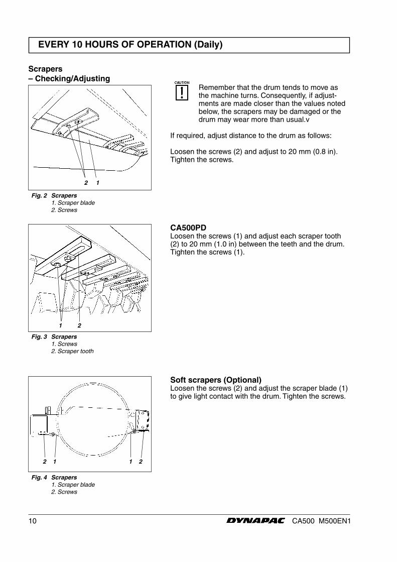
Remember that the drum tends to move as the machine turns. Consequently, if adjust-ments are made closer than the values noted below, the scrapers may be damaged or the drum may wear more than usual.v
If required, adjust distance to the drum as follows:
Loosen the screws (2) and adjust to 20 mm (0.8 in).Tighten the screws.
Scrapers – Checking/Adjusting
Fig. 2 Scrapers 1. Scraper blade 2. Screws
Fig. 3 Scrapers 1. Screws 2. Scraper tooth
CA500PDLoosen the screws (1) and adjust each scraper tooth (2) to 20 mm (1.0 in) between the teeth and the drum. Tighten the screws (1).
2 1
Soft scrapers (Optional)Loosen the screws (2) and adjust the scraper blade (1) to give light contact with the drum. Tighten the screws.
2 1 1 2
Fig. 4 Scrapers 1. Scraper blade 2. Screws
1 2
11CA500 M500EN1
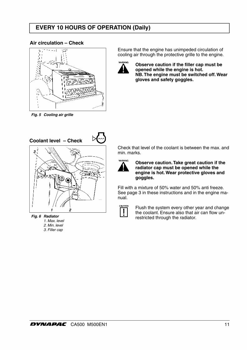
Ensure that the engine has unimpeded circulation of cooling air through the protective grille to the engine.
Observe caution if the filler cap must be opened while the engine is hot.NB. The engine must be switched off. Wear gloves and safety goggles.
Air circulation – Check
Fig. 5 Cooling air grille
EVERY 10 HOURS OF OPERATION (Daily)
3
1 2
Fig. 6 Radiator 1. Max. level 2. Min. level 3. Filler cap
Check that level of the coolant is between the max. and min. marks.
Observe caution. Take great caution if the radiator cap must be opened while the engine is hot. Wear protective gloves and goggles.
Fill with a mixture of 50% water and 50% anti freeze. See page 3 in these instructions and in the engine ma-nual.
Flush the system every other year and change the coolant. Ensure also that air can flow un-restricted through the radiator.
Coolant level – Check

12 CA500 M500EN1
Hydraulic reservoir– Checking the fluid level
Refuel every day. Top off to the lower edge of the filler pipe. Use diesel fuel in accordance with the engine manufacturer’s specifications.
Stop the diesel engine. Short (press) the filler gun against a non-insulated part of the roller before refueling, and against the filler pipe (1) while refueling is in progress.
The fuel tank holds 320 litres (85 gal).
EVERY 10 HOURS OF OPERATION (Daily)
Engine – Checking the oil level
Fig. 7 Engine compartment 1. Oil dipstick
Place the roller on a level base. The engine must be switched off and the parking brake applied for all checking and adjustments on the roller unless stated otherwise.
Observe caution. Beware of hot parts of the engine and hot radiator when taking out the oil dipstick. Wear gloves and safety goggles.
The dipstick is on the right-hand side of the engine.
Pull the dipstick (1) up and check that the oil level is between the upper and lower marks. See the engine manual for further details.
1
Fig. 8 Fuel tank 1. Filler pipe 2. Fuel pre-filter
Fuel tank – Refueling
1
Fig. 9 Hydraulic reservoir 1. Sight glass 2. Filler pipe
Place the roller on level ground and check that the fluid level is between the max. and min. marks in the sight glass (1). Top off with hydraulic fluid according to the lubricant specification if the level is too low.
2
1

13CA500 M500EN1
EVERY 10 HOURS OF OPERATION (Daily)
Brakes – Check
Fig. 10 Control panel 1. Reserve/parking brake knob 2. Forward/reverse lever 3. Brake warning lamp
Check brake operation as follows:
Drive the roller slowly forward.
Press down the reserve/parking brake knob (1). The brake warning lamp (3) on the instrument panel should light and the roller should stop.
After testing the brakes, set the forward/reverse lever (2) in neutral.
Pull out the reserve/parking brake knob.
The roller is now ready for operation.
13
2
14 CA500 M500EN1
EVERY 50 HOURS OF OPERATION (Weekly)
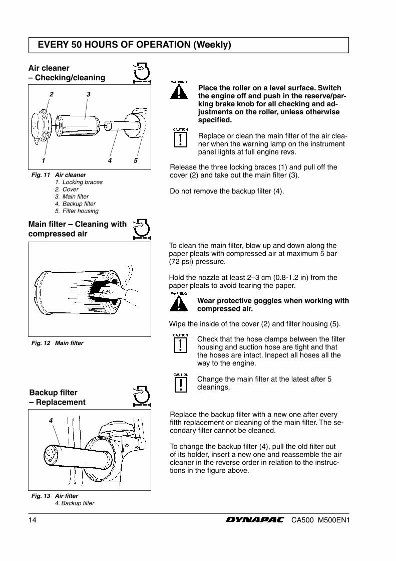
Air cleaner – Checking/cleaning
Main filter – Cleaning with compressed air
Fig. 12 Main filter
2 3
Fig. 11 Air cleaner 1. Locking braces 2. Cover 3. Main filter 4. Backup filter 5. Filter housing
Place the roller on a level surface. Switch the engine off and push in the reserve/par-king brake knob for all checking and ad-justments on the roller, unless otherwise specified.
Replace or clean the main filter of the air clea-ner when the warning lamp on the instrument panel lights at full engine revs.
Release the three locking braces (1) and pull off the cover (2) and take out the main filter (3).
Do not remove the backup filter (4).
1 4 5
Replace the backup filter with a new one after every fifth replacement or cleaning of the main filter. The se-condary filter cannot be cleaned.
To change the backup filter (4), pull the old filter out of its holder, insert a new one and reassemble the air cleaner in the reverse order in relation to the instruc-tions in the figure above.
Fig. 13 Air filter 4. Backup filter
Backup filter – Replacement
4
To clean the main filter, blow up and down along the paper pleats with compressed air at maximum 5 bar (72 psi) pressure.
Hold the nozzle at least 2–3 cm (0.8-1.2 in) from the paper pleats to avoid tearing the paper.
Wear protective goggles when working with compressed air.
Wipe the inside of the cover (2) and filter housing (5).
Check that the hose clamps between the filter housing and suction hose are tight and that the hoses are intact. Inspect all hoses all the way to the engine.
Change the main filter at the latest after 5 cleanings.
15CA500 M500EN1
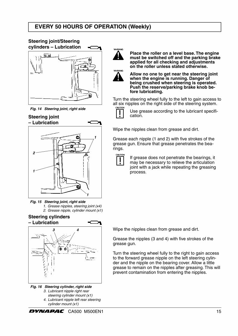
Steering cylinders – Lubrication
Steering joint – Lubrication
Steering joint/Steering cylinders – Lubrication
Fig. 14 Steering joint, right side
Place the roller on a level base. The engine must be switched off and the parking brake applied for all checking and adjustments on the roller unless stated otherwise.
Allow no one to get near the steering joint when the engine is running. Danger of being crushed when steering is operated. Push the reserve/parking brake knob be-fore lubricating.
Turn the steering wheel fully to the left to gain access to all six nipples on the right side of the steering system.
Use grease according to the lubricant specifi-cation.
Fig. 16 Steering cylinder, right side 3. Lubricant nipple right rear steering cylinder mount (x1) 4. Lubricant nipple left rear steering cylinder mount (x1)
1
Fig. 15 Steering joint, right side 1. Grease nipples, steering joint (x4) 2. Grease nipple, cylinder mount (x1)
EVERY 50 HOURS OF OPERATION (Weekly)
Wipe the nipples clean from grease and dirt.
Grease the nipples (3 and 4) with five strokes of the grease gun.
Turn the steering wheel fully to the right to gain access to the forward grease nipple on the left steering cylin-der and the nipple on the bearing cover. Allow a little grease to remain on the nipples after greasing. This will prevent contamination from entering the nipples.
1
2
3 4
Wipe the nipples clean from grease and dirt.
Grease each nipple (1 and 2) with five strokes of the grease gun. Ensure that grease penetrates the bea-rings.
If grease does not penetrate the bearings, it may be necessary to relieve the articulation joint with a jack while repeating the greasing process.1
16 CA500 M500EN1
EVERY 50 HOURS OF OPERATION (Weekly)
12
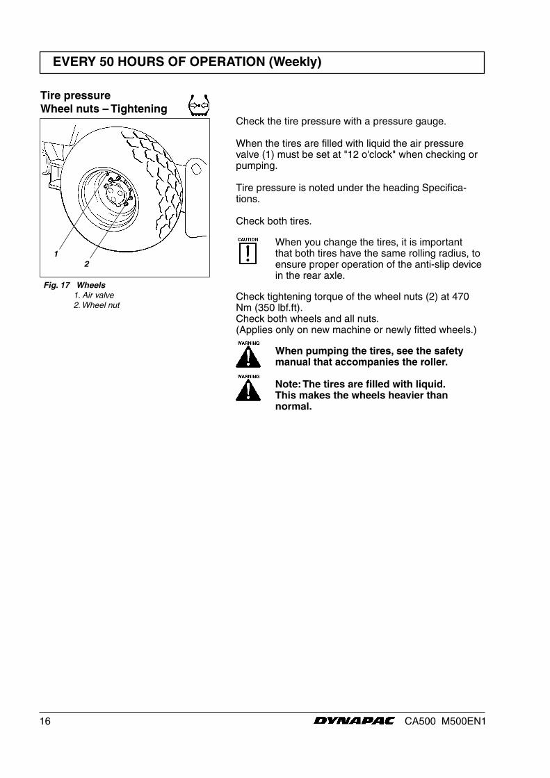
Tire pressureWheel nuts – Tightening
Check the tire pressure with a pressure gauge.
When the tires are filled with liquid the air pressure valve (1) must be set at "12 o'clock" when checking or pumping.
Tire pressure is noted under the heading Specifica-tions.
Check both tires.
When you change the tires, it is important that both tires have the same rolling radius, to ensure proper operation of the anti-slip device in the rear axle.
Check tightening torque of the wheel nuts (2) at 470 Nm (350 lbf.ft).Check both wheels and all nuts.(Applies only on new machine or newly fitted wheels.)
When pumping the tires, see the safety manual that accompanies the roller.
Note: The tires are filled with liquid.This makes the wheels heavier than normal.
Fig. 17 Wheels 1. Air valve 2. Wheel nut
17CA500 M500EN1
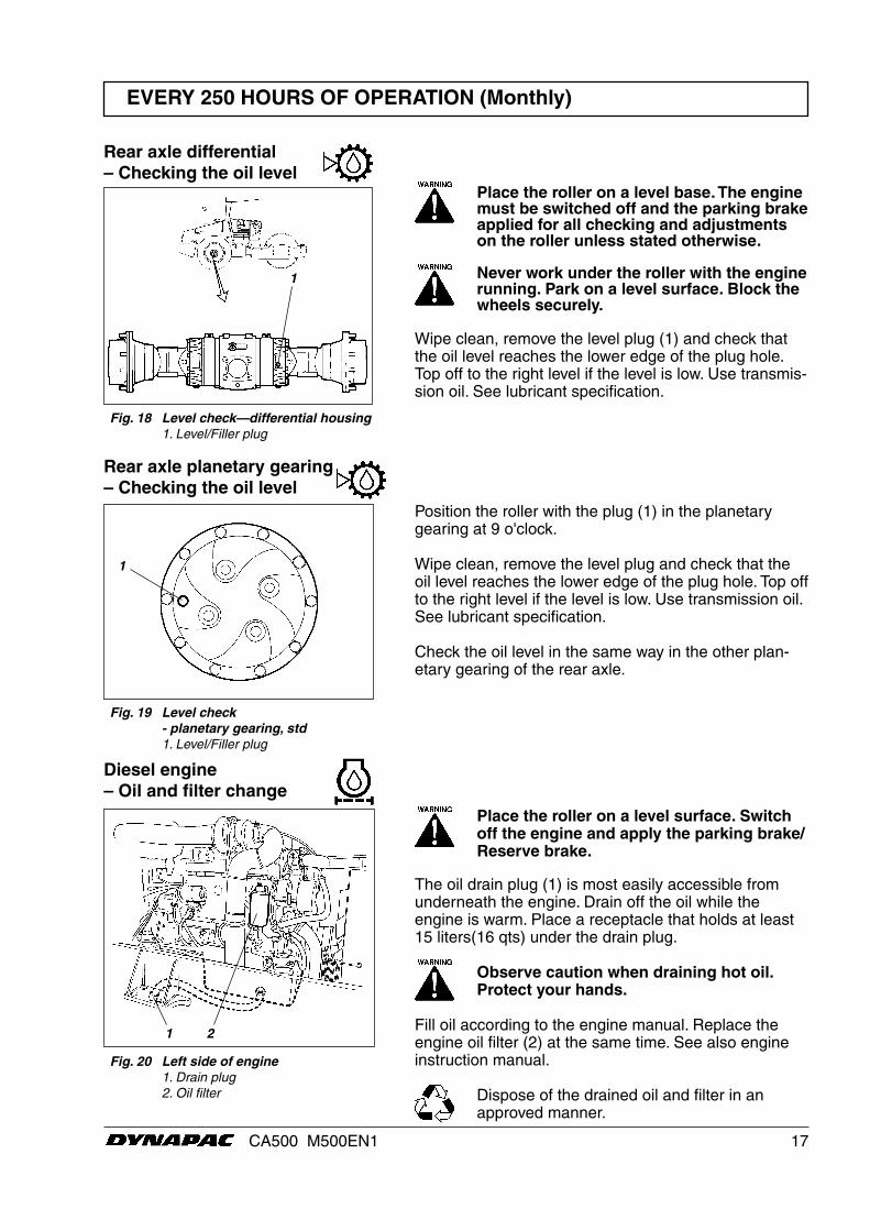
Rear axle planetary gearing– Checking the oil level
EVERY 250 HOURS OF OPERATION (Monthly)
Rear axle differential – Checking the oil level
Place the roller on a level base. The engine must be switched off and the parking brake applied for all checking and adjustments on the roller unless stated otherwise.
Never work under the roller with the engine running. Park on a level surface. Block the wheels securely.
Wipe clean, remove the level plug (1) and check that the oil level reaches the lower edge of the plug hole. Top off to the right level if the level is low. Use transmis-sion oil. See lubricant specification.
1
Fig. 18 Level check—differential housing 1. Level/Filler plug
1
1 2
Fig. 19 Level check - planetary gearing, std 1. Level/Filler plug
Position the roller with the plug (1) in the planetary gearing at 9 o'clock.
Wipe clean, remove the level plug and check that the oil level reaches the lower edge of the plug hole. Top off to the right level if the level is low. Use transmission oil. See lubricant specification.
Check the oil level in the same way in the other plan-etary gearing of the rear axle.
Fig. 20 Left side of engine 1. Drain plug 2. Oil filter
Diesel engine – Oil and filter change
Place the roller on a level surface. Switch off the engine and apply the parking brake/Reserve brake.
The oil drain plug (1) is most easily accessible from underneath the engine. Drain off the oil while the engine is warm. Place a receptacle that holds at least 15 liters(16 qts) under the drain plug.
Observe caution when draining hot oil. Protect your hands.
Fill oil according to the engine manual. Replace the engine oil filter (2) at the same time. See also engine instruction manual.
Dispose of the drained oil and filter in an approved manner.
18 CA500 M500EN1
EVERY 250 HOURS OF OPERATION (Monthly)
1
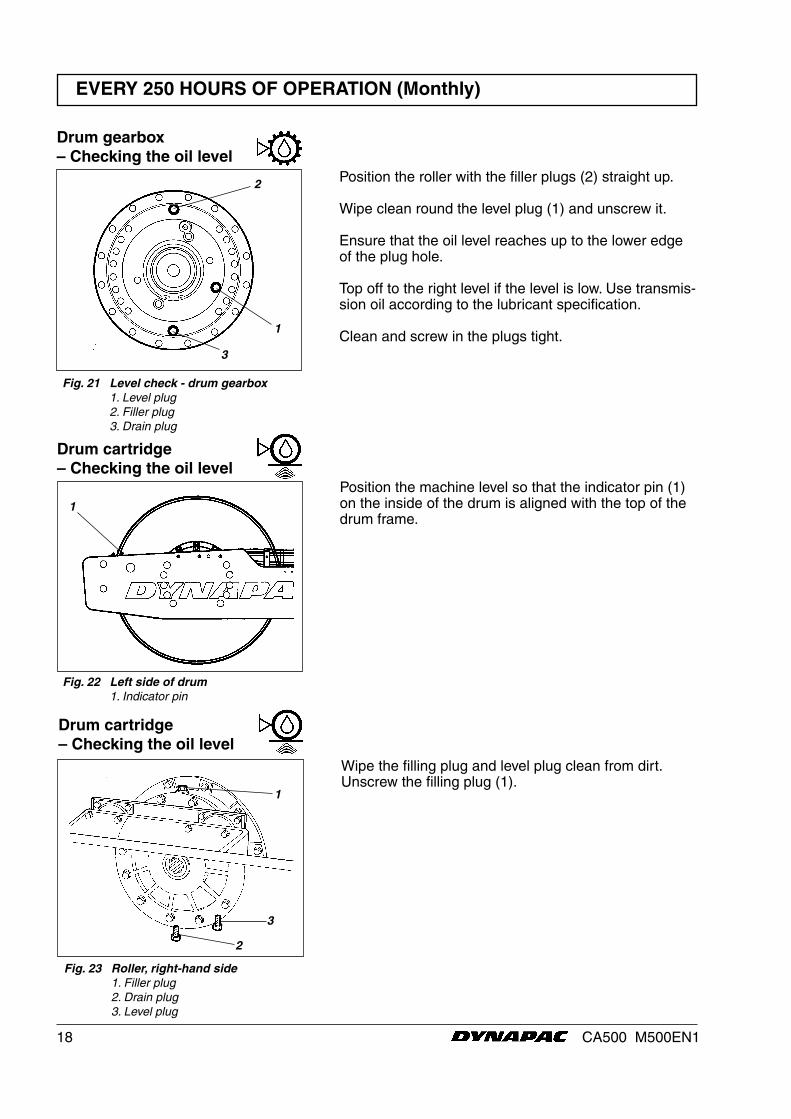
Drum cartridge– Checking the oil level
Position the machine level so that the indicator pin (1) on the inside of the drum is aligned with the top of the drum frame.
Fig. 22 Left side of drum 1. Indicator pin
Fig. 23 Roller, right-hand side 1. Filler plug 2. Drain plug 3. Level plug
Drum cartridge – Checking the oil level
Wipe the filling plug and level plug clean from dirt. Unscrew the filling plug (1).
1
2
3
Fig. 21 Level check - drum gearbox 1. Level plug 2. Filler plug 3. Drain plug
Drum gearbox– Checking the oil level
1
2 Position the roller with the filler plugs (2) straight up.
Wipe clean round the level plug (1) and unscrew it.
Ensure that the oil level reaches up to the lower edge of the plug hole.
Top off to the right level if the level is low. Use transmis-sion oil according to the lubricant specification.
Clean and screw in the plugs tight.3
19CA500 M500EN1
EVERY 250 HOURS OF OPERATION (Monthly)
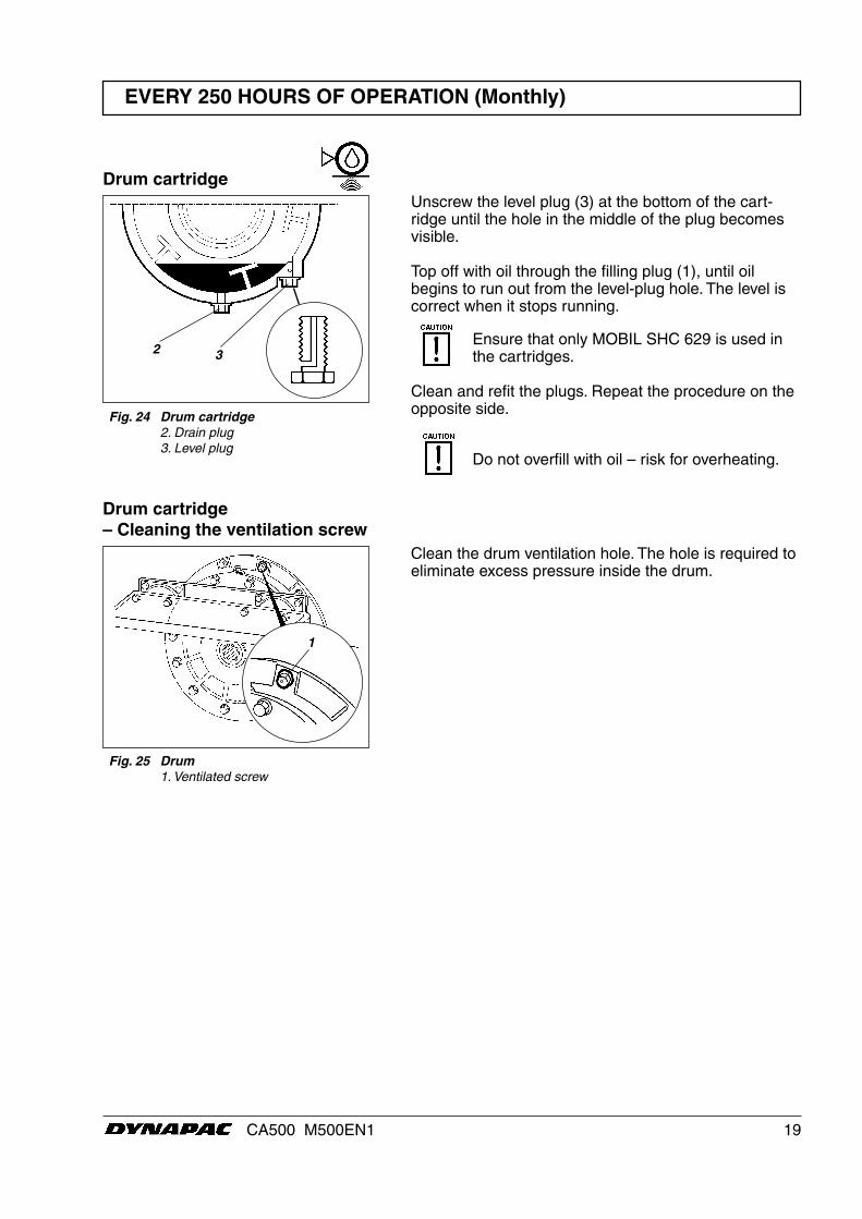
Fig. 25 Drum 1. Ventilated screw
Drum cartridge – Cleaning the ventilation screw
Clean the drum ventilation hole. The hole is required to eliminate excess pressure inside the drum.
1
Unscrew the level plug (3) at the bottom of the cart-ridge until the hole in the middle of the plug becomes visible.
Top off with oil through the filling plug (1), until oil begins to run out from the level-plug hole. The level is correct when it stops running.
Ensure that only MOBIL SHC 629 is used in the cartridges.
Clean and refit the plugs. Repeat the procedure on the opposite side.
Do not overfill with oil – risk for overheating.
Drum cartridge
3 2
Fig. 24 Drum cartridge 2. Drain plug 3. Level plug
20 CA500 M500EN1
EVERY 250 HOURS OF OPERATION (Monthly)
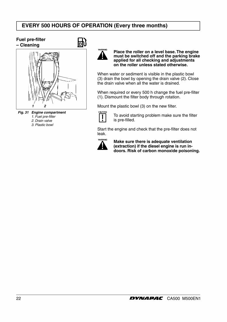
Check all rubber elements (1), replace all of the ele-ments if more than 25% of them on one side of the drum are cracked deeper than 10–15 mm (0.4-0.6 in).
Use the blade of a knife or pointed object to assist when checking.
Ensure that the fastening screws (2) are tightened.
Fig. 28 Drum, vibration side 1. Rubber element 2. Fastening screws
Rubber elements and fastening screws – Check
1
2
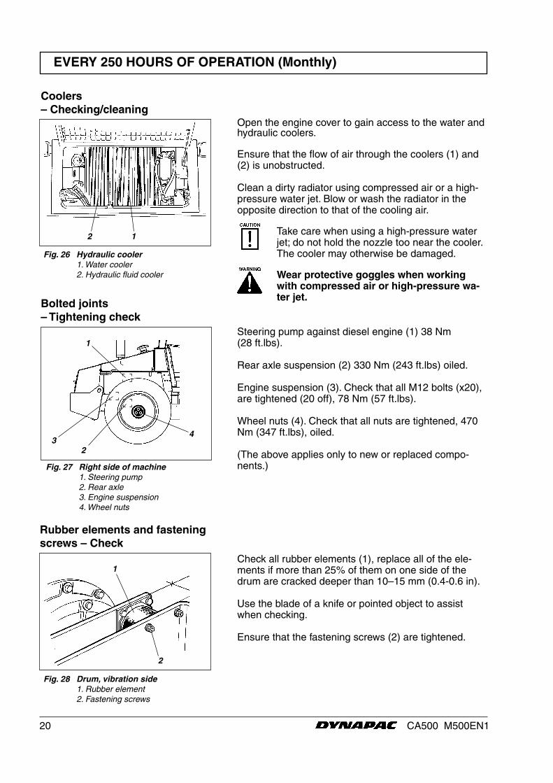
Fig. 26 Hydraulic cooler 1. Water cooler 2. Hydraulic fluid cooler
Open the engine cover to gain access to the water and hydraulic coolers.
Ensure that the flow of air through the coolers (1) and (2) is unobstructed.
Clean a dirty radiator using compressed air or a high-pressure water jet. Blow or wash the radiator in the opposite direction to that of the cooling air.
Take care when using a high-pressure water jet; do not hold the nozzle too near the cooler.The cooler may otherwise be damaged.
Wear protective goggles when working with compressed air or high-pressure wa-ter jet.
Coolers – Checking/cleaning
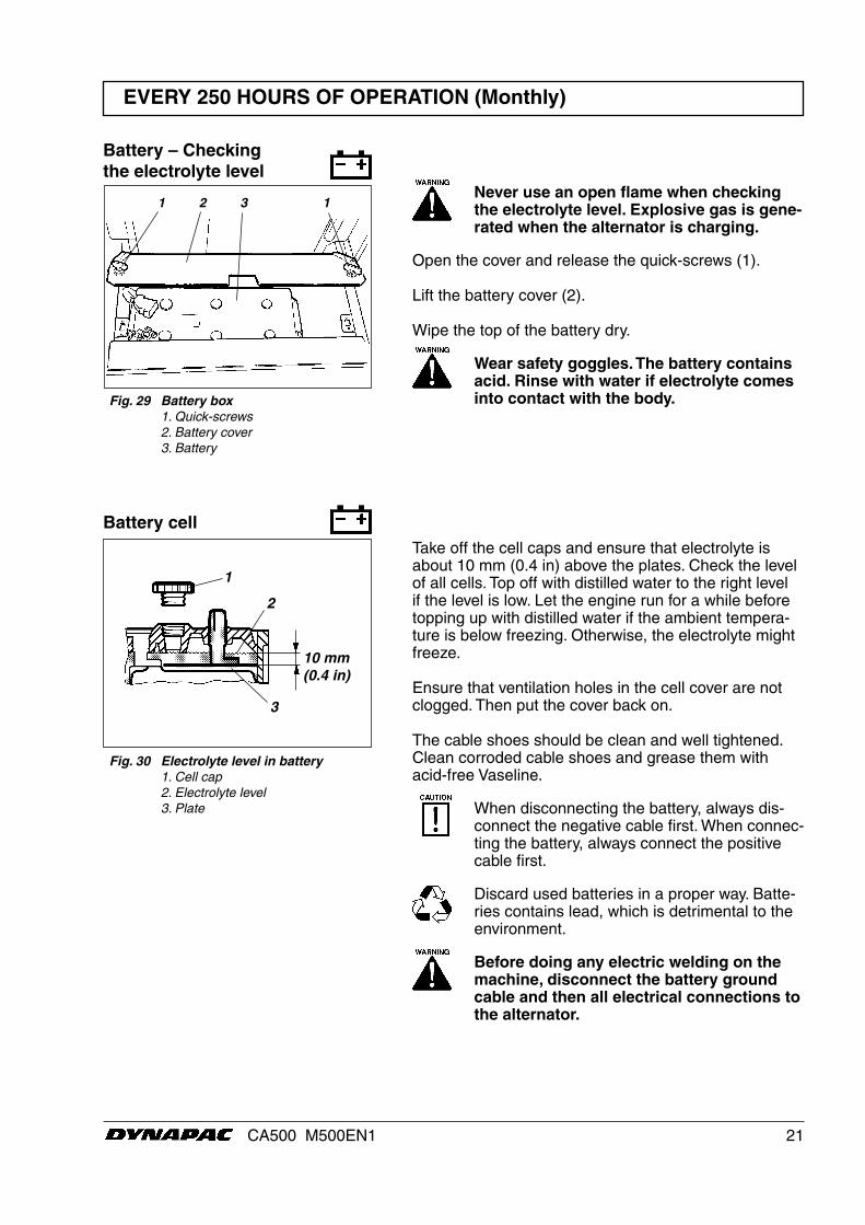
Bolted joints– Tightening check
Fig. 27 Right side of machine 1. Steering pump 2. Rear axle 3. Engine suspension 4. Wheel nuts
Steering pump against diesel engine (1) 38 Nm(28 ft.lbs).
Rear axle suspension (2) 330 Nm (243 ft.lbs) oiled.
Engine suspension (3). Check that all M12 bolts (x20), are tightened (20 off), 78 Nm (57 ft.lbs).
Wheel nuts (4). Check that all nuts are tightened, 470 Nm (347 ft.lbs), oiled.
(The above applies only to new or replaced compo-nents.)
32
1
4
12
21CA500 M500EN1
Take off the cell caps and ensure that electrolyte is about 10 mm (0.4 in) above the plates. Check the level of all cells. Top off with distilled water to the right level if the level is low. Let the engine run for a while before topping up with distilled water if the ambient tempera-ture is below freezing. Otherwise, the electrolyte might freeze.
Ensure that ventilation holes in the cell cover are not clogged. Then put the cover back on.
The cable shoes should be clean and well tightened.Clean corroded cable shoes and grease them with acid-free Vaseline.
When disconnecting the battery, always dis-connect the negative cable first. When connec-ting the battery, always connect the positive cable first.
Discard used batteries in a proper way. Batte-ries contains lead, which is detrimental to the environment.
Before doing any electric welding on the machine, disconnect the battery ground cable and then all electrical connections to the alternator.
Battery cell
Fig. 30 Electrolyte level in battery 1. Cell cap 2. Electrolyte level 3. Plate
EVERY 250 HOURS OF OPERATION (Monthly)
1
2
3
10 mm(0.4 in)
Never use an open flame when checking the electrolyte level. Explosive gas is gene-rated when the alternator is charging.
Open the cover and release the quick-screws (1).
Lift the battery cover (2).
Wipe the top of the battery dry.
Wear safety goggles. The battery contains acid. Rinse with water if electrolyte comes into contact with the body.
Battery – Checking the electrolyte level
1 2 3 1
Fig. 29 Battery box 1. Quick-screws 2. Battery cover 3. Battery
22 CA500 M500EN1
EVERY 500 HOURS OF OPERATION (Every three months)
1 2
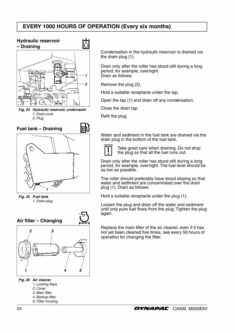
Fig. 31 Engine compartment 1. Fuel pre-filter 2. Drain valve 3. Plastic bowl
Fuel pre-filter – Cleaning
Place the roller on a level base. The engine must be switched off and the parking brake applied for all checking and adjustments on the roller unless stated otherwise.
When water or sediment is visible in the plastic bowl (3) drain the bowl by opening the drain valve (2). Close the drain valve when all the water is drained.
When required or every 500 h change the fuel pre-filter (1). Dismount the filter body through rotation.
Mount the plastic bowl (3) on the new filter.
To avoid starting problem make sure the filter is pre-filled.
Start the engine and check that the pre-filter does not leak.
Make sure there is adequate ventilation (extraction) if the diesel engine is run in-doors. Risk of carbon monoxide poisoning.

23CA500 M500EN1
Place the roller on a level base. The engine must be switched off and the parking brake applied for all checking and adjustments on the roller unless stated otherwise.
Loosen the cap/breather filter (2) on top of the reser-voir to relieve any excess pressure inside.
Ensure that the breather filter (2) is not clogged, air must have unobstructed passage through the cap in both directions.
If clogged in either direction, clean with a little diesel oil and blow with compressed air until free passage is assured, or replace the cap with a new one.
Wear protective goggles when working with compressed air.
Clean thoroughly round the hydraulic filter. Remove the hydraulic filter (1) and scrap it. They are of the expen-dable type and cannot be cleaned.
Ensure that the old sealing ring is not left on the filter holder. Leakage may otherwise occur between the new and the old seals.
Thoroughly clean the sealing surface of the filter holder.
Apply a thin coat of fresh hydraulic fluid on the new filter seal. Screw on the filter by hand.
First, screw on until the filter seal lies against the filter holder. Then screw a further half turn. Do not tighten the filter too hard, which could damage the gasket.
Start the engine and ensure that there is no leakage of hydraulic fluid from the filter. Check the fluid level in the sight glass (3) and top off as required.
Ensure that ventilation (extraction) is ade-quate if the engine is run indoors.Risk of carbon monoxide poisoning.
Fig. 33 Engine compartment 1. Hydraulic filter (x1)
Fig. 32 Hydraulic reservoir 2. Filler cap/Breather filter 3. Sight glass
3
2
1
EVERY 1000 HOURS OF OPERATION (Every six months)
Hydraulic filter – Replacement
24 CA500 M500EN1
Water and sediment in the fuel tank are drained via the drain plug in the bottom of the fuel tank.
Take great care when draining. Do not drop the plug so that all the fuel runs out.
Drain only after the roller has stood still during a long period, for example, overnight. The fuel level should be as low as possible.
The roller should preferably have stood sloping so that water and sediment are concentrated over the drain plug (1). Drain as follows:
Hold a suitable receptacle under the plug (1).
Loosen the plug and drain off the water and sediment until only pure fuel flows from the plug. Tighten the plug again.
EVERY 1000 HOURS OF OPERATION (Every six months)
Fig. 35 Fuel tank 1. Drain plug
Fuel tank – Draining
1
Replace the main filter of the air cleaner, even if it has not yet been cleaned five times, see every 50 hours of operation for changing the filter.
2 3
Fig. 36 Air cleaner 1. Locking flaps 2. Cover 3. Main filter 4. Backup filter 5. Filter housing
1 4 5
Air filter – Changing
Hydraulic reservoir – Draining
Condensation in the hydraulic reservoir is drained via the drain plug (1).
Drain only after the roller has stood still during a long period, for example, overnight.Drain as follows:
Remove the plug (2).
Hold a suitable receptacle under the tap.
Open the tap (1) and drain off any condensation.
Close the drain tap.
Refit the plug.
Fig. 34 Hydraulic reservoir, underneath 1. Drain cock 2. Plug
1
2
25CA500 M500EN1
EVERY 1000 HOURS OF OPERATION (Every six months)
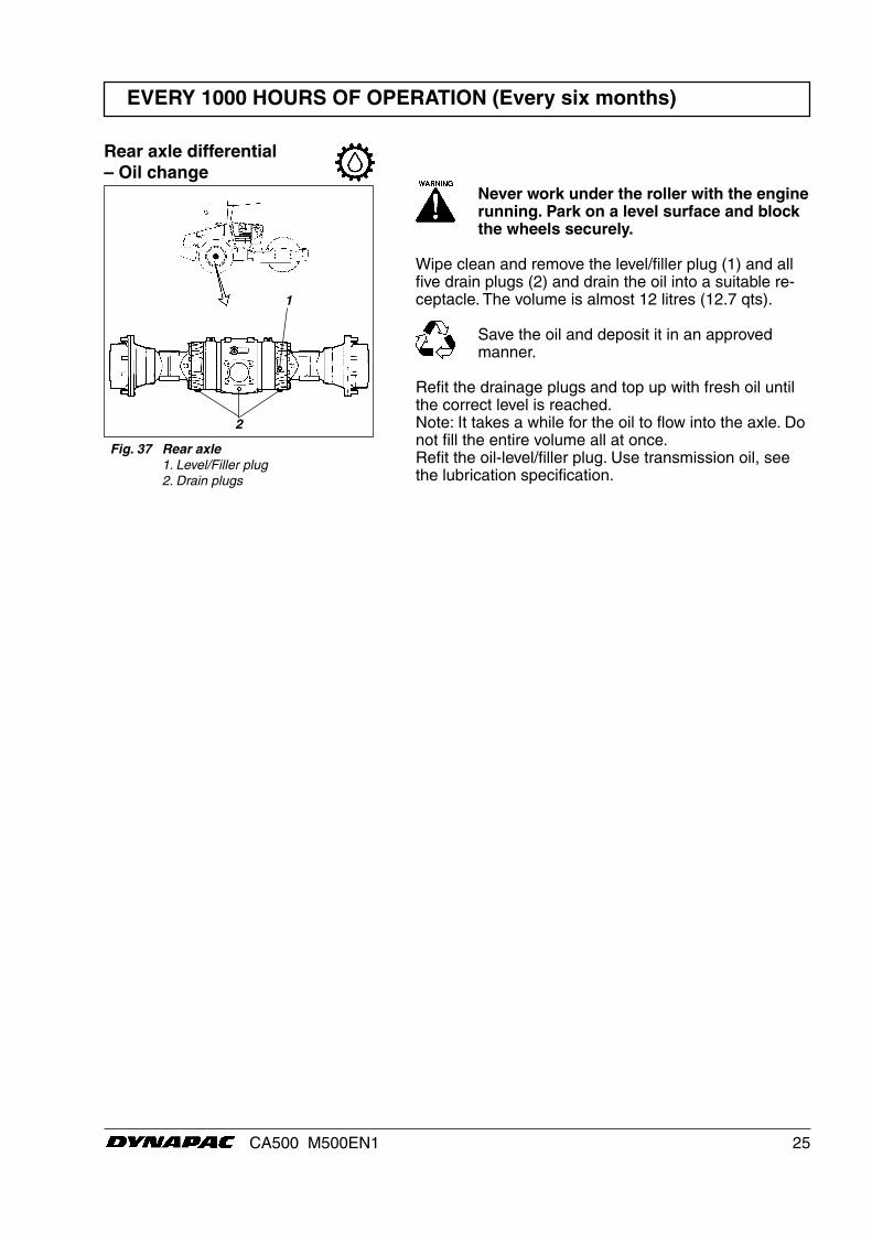
Fig. 37 Rear axle 1. Level/Filler plug 2. Drain plugs
Rear axle differential – Oil change
1
2
Never work under the roller with the engine running. Park on a level surface and block the wheels securely.
Wipe clean and remove the level/filler plug (1) and all five drain plugs (2) and drain the oil into a suitable re-ceptacle. The volume is almost 12 litres (12.7 qts).
Save the oil and deposit it in an approved manner.
Refit the drainage plugs and top up with fresh oil until the correct level is reached.Note: It takes a while for the oil to flow into the axle. Do not fill the entire volume all at once.Refit the oil-level/filler plug. Use transmission oil, see the lubrication specification.
26 CA500 M500EN1
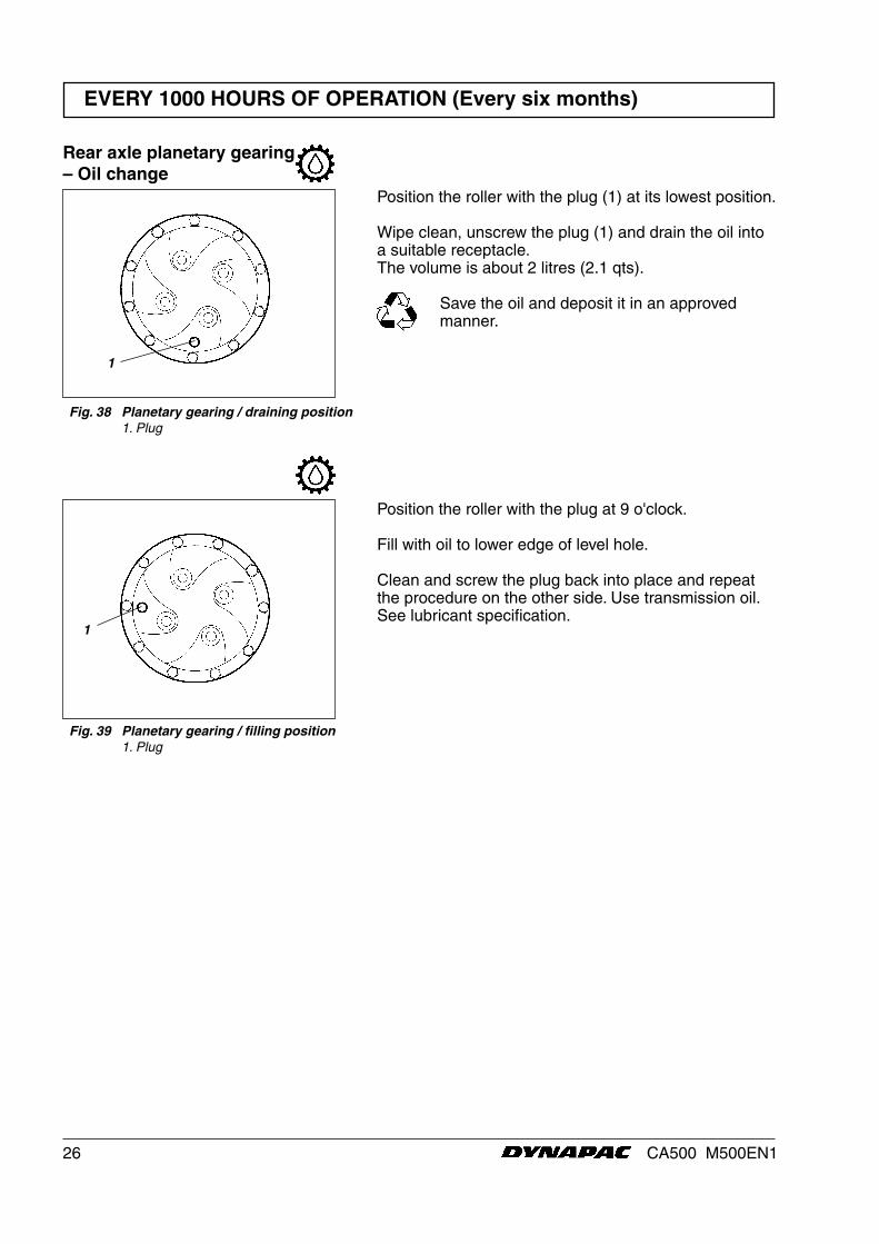
Rear axle planetary gearing– Oil change
Fig. 38 Planetary gearing / draining position 1. Plug
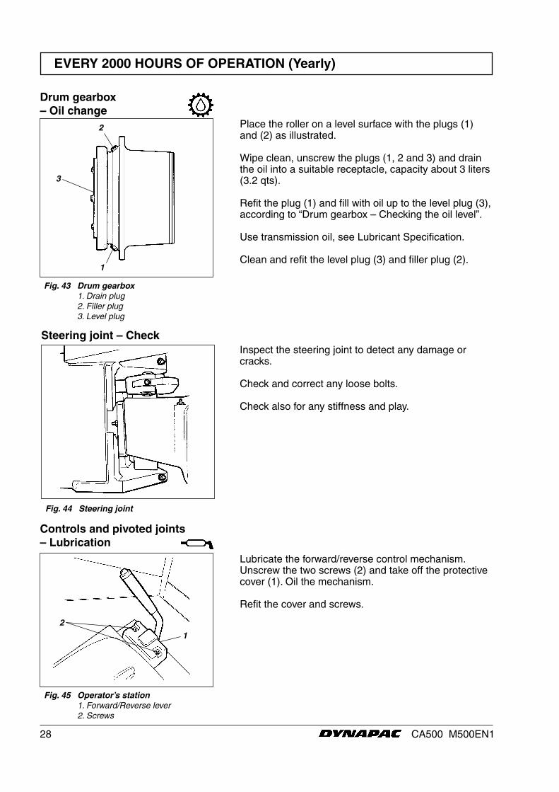
Fig. 39 Planetary gearing / filling position 1. Plug
EVERY 1000 HOURS OF OPERATION (Every six months)
Position the roller with the plug (1) at its lowest position.
Wipe clean, unscrew the plug (1) and drain the oil into a suitable receptacle. The volume is about 2 litres (2.1 qts).
Save the oil and deposit it in an approved manner.
Position the roller with the plug at 9 o'clock.
Fill with oil to lower edge of level hole.
Clean and screw the plug back into place and repeat the procedure on the other side. Use transmission oil. See lubricant specification.
1
1

27CA500 M500EN1
Hydraulic reservoir – Changing the fluid
Fig. 40 Hydraulic reservoir, underneath 1. Stop cock 2. Plug
EVERY 2000 HOURS OF OPERATION (Yearly)
Drum cartridge – Oil change
Fig. 42 Drum, right side 1. Filler plug 2. Drain plug 3. Level plug
Place a receptacle for about 5 litres (5.3 qts) underne-ath the level/drain plug (2).
Save the oil and deposit it in an approved manner.
Clean and unscrew the filler plug (1) and the drain plug (2).
Allow all of the oil to drain off. Fit the drain plug, and fill with fresh synthetic oil according to instructions under the heading “Drum cartridge – Checking the oil level”.
Repeat the procedure on the opposite side.
Ensure that only MOBIL SHC 629 is used in the cartridges.
Place the roller on a level surface. Switch the engine off and push in the reserve/parking brake knob for all checking and adjust-ments on the roller, unless otherwise speci-fied.
Observe caution when draining hot oil. Pro-tect your hands.
Obtain a container for collecting the used fluid. The con-tainer should have a volume of at least 60 litres (16 gal).
A suitable container may be an empty oil drum or simi-lar item which is placed beside the roller. The fluid then runs in a hose from the drainage plug (1) to the oil drum, after the plug (2) has been removed and the tap opened.
Save the oil and deposit it in an approved man-ner.
Fill up with fresh hydraulic fluid as per the instructions under the heading “Hydraulic reservoir – Check fluid level”. Replace the hydraulic fluid filters at the same time.
Start the diesel engine and operate the various hydrau-lic functions.
Make sure there is adequate ventilation (ex-traction) if the diesel engine is run indoors. Risk of carbon monoxide poisoning.
Check the fluid level and top up if necessary.
Position the machine level so that the indicator pin (1) on the inside of the drum is aligned with the top of the drum frame.
1
Fig. 41 Left side of drum 1. Indicator pin
Drum cartridge – Oil change
1
2
3
1
2
28 CA500 M500EN1
EVERY 2000 HOURS OF OPERATION (Yearly)
Drum gearbox – Oil change
Fig. 43 Drum gearbox 1. Drain plug 2. Filler plug 3. Level plug
2
1
3
Place the roller on a level surface with the plugs (1) and (2) as illustrated.
Wipe clean, unscrew the plugs (1, 2 and 3) and drain the oil into a suitable receptacle, capacity about 3 liters (3.2 qts).
Refit the plug (1) and fill with oil up to the level plug (3), according to “Drum gearbox – Checking the oil level”.
Use transmission oil, see Lubricant Specification.
Clean and refit the level plug (3) and filler plug (2).
Steering joint – CheckInspect the steering joint to detect any damage or cracks.
Check and correct any loose bolts.
Check also for any stiffness and play.
Fig. 44 Steering joint
Fig. 45 Operator’s station 1. Forward/Reverse lever 2. Screws
Controls and pivoted joints – Lubrication
2
Lubricate the forward/reverse control mechanism. Unscrew the two screws (2) and take off the protective cover (1). Oil the mechanism.
Refit the cover and screws.
1
29CA500 M500EN1
LONG-TERM STORAGE
* See manufacturer’s instructions in the engine ma-nual that accompanies the roller.
* Remove the battery from the roller, clean it, check that the electrolyte level is correct and trickle charge the battery once a month.
* Cover the air cleaner or its opening with plastic or tape. Cover the exhaust opening. This is necessary to prevent moisture from entering the engine.
Fill the fuel tank completely to prevent condensation.
Drain off any condensation water and fill the hydrau-lic reservoir to the upper mark.
Lubricate the steering joint bearings and the ste-
ering cylinder’s two bearings with grease. Grease the steering cylinder’s piston with conserva-
tion grease. Grease also the engine compartment cover’s hing-
es, the seat slide rails, the engine-speed control and the forward/reverse control mechanism.
Ensure that tire pressure is 110 kPa (1.1 kp/ cm2).
* Place the instrument cover on the steering column. Cover the entire machine with a tarpaulin, which should hand some way off the ground. If possible, store the roller indoors, preferably in a building with a uniform temperature.
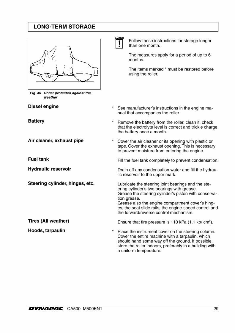
Follow these instructions for storage longer than one month:
The measures apply for a period of up to 6 months.
The items marked * must be restored before using the roller.
Battery
Diesel engine
Air cleaner, exhaust pipe
Fuel tank
Hydraulic reservoir
Steering cylinder, hinges, etc.
Hoods, tarpaulin
Tires (All weather)
Fig. 46 Roller protected against the weather

30 CA500 M500EN1
SPECIAL INSTRUCTIONS
The temperature limits apply to standard versions of the roller.
Rollers that are fitted with additional equipment, such as noise suppression, etc., may require extra observa-tion in the higher temperature ranges.
When washing the machine, do not direct the jet of water directly at the fuel or hydraulic fluid tank covers. This is particularly important when using a high-pressure washing unit.
Do not spray water directly on electric components or the instrument panel. Put a plastic bag over the filler cap of the fuel tank and secure with a rubber band. This will prevent water from entering the venting hole in the filler cap. This could otherwise cause operational disturbance, for example, a clogged filter.
In the event of fire in the machine, use an ABE-powder fire extinguisher if possible. A BE type carbon dioxide fire extinguisher may also be used.
If the roller is equipped with a protective structure (ROPS, Roll Over Protective Structure), or protective cab, never subject the structure or cab to welding or drilling. Never attempt to repair a damaged structure or cab; they must be replaced with new ones.
When using an auxiliary battery to assist starting, always connect the positive terminal of the auxiliary battery to the positive terminal of the roller battery, and negative to negative.
Starting aid
Protective structure (ROPS)
Fire fighting
High-pressure washing
Temperature
Standard oils and other recom-mended fluids
Higher ambient temperaturemax. +50°C (122°F)
Upon delivery from the factory, the various systems and components are filled with the oils specified see lubricant specification and they can be used at ambient temperatures from -10°C to +40°C (14°F - 104°F).
A maximum temperature of +35°C (95°F) app-lies for biological hydraulic fluid.
When operating in hotter ambient temperatures, but up to max. +50°C (122°F), the following instructions apply:
The diesel engine can handle this temperature with the standard oil, but the following oils must be used in the other components:Hydraulic system with mineral fluid: Shell Tellus TX100 or corresponding.Other components using transmission oil:Shell Spirax HD 85W/140 or corresponding.
31CA500 M500EN1
ELECTRICAL SYSTEM, FUSES
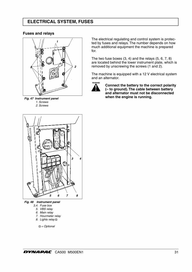
The electrical regulating and control system is protec-ted by fuses and relays. The number depends on how much additional equipment the machine is prepared for.
The two fuse boxes (3, 4) and the relays (5, 6, 7, 8) are located behind the lower instrument plate, which is removed by unscrewing the screws (1 and 2).
The machine is equipped with a 12 V electrical system and an alternator.
Connect the battery to the correct polarity (– to ground). The cable between battery and alternator must not be disconnected when the engine is running.Fig. 47 Instrument panel
1. Screws 2. Screws
Fuses and relays
2 2
1
5 6 7 8
3 4
Fig. 48 Instrument panel 3,4. Fuse box 5. VBS relay 6. Main relay 7. Hourmeter relay 8. Lights relay
= Optional
32 CA500 M500EN1
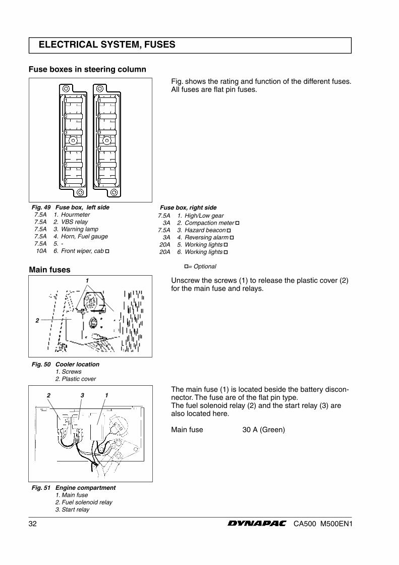
Fig. 51 Engine compartment 1. Main fuse 2. Fuel solenoid relay 3. Start relay
ELECTRICAL SYSTEM, FUSES
Fuse boxes in steering column
Fig. 49 Fuse box, left side 7.5A 1. Hourmeter 7.5A 2. VBS relay 7.5A 3. Warning lamp 7.5A 4. Horn, Fuel gauge 7.5A 5. - 10A 6. Front wiper, cab
Fig. shows the rating and function of the different fuses. All fuses are flat pin fuses.
Fuse box, right side 7.5A 1. High/Low gear 3A 2. Compaction meter 7.5A 3. Hazard beacon 3A 4. Reversing alarm 20A 5. Working lights 20A 6. Working lights
= OptionalMain fuses
Fig. 50 Cooler location 1. Screws 2. Plastic cover
Unscrew the screws (1) to release the plastic cover (2) for the main fuse and relays.
1
The main fuse (1) is located beside the battery discon-nector. The fuse are of the flat pin type.The fuel solenoid relay (2) and the start relay (3) are also located here.
Main fuse 30 A (Green)
132
2